Embed Size (px)
Citation preview
1
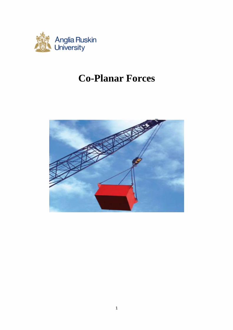
Co-Planar Forces
2
Co-Planar Forces
Forces in Equilibrium
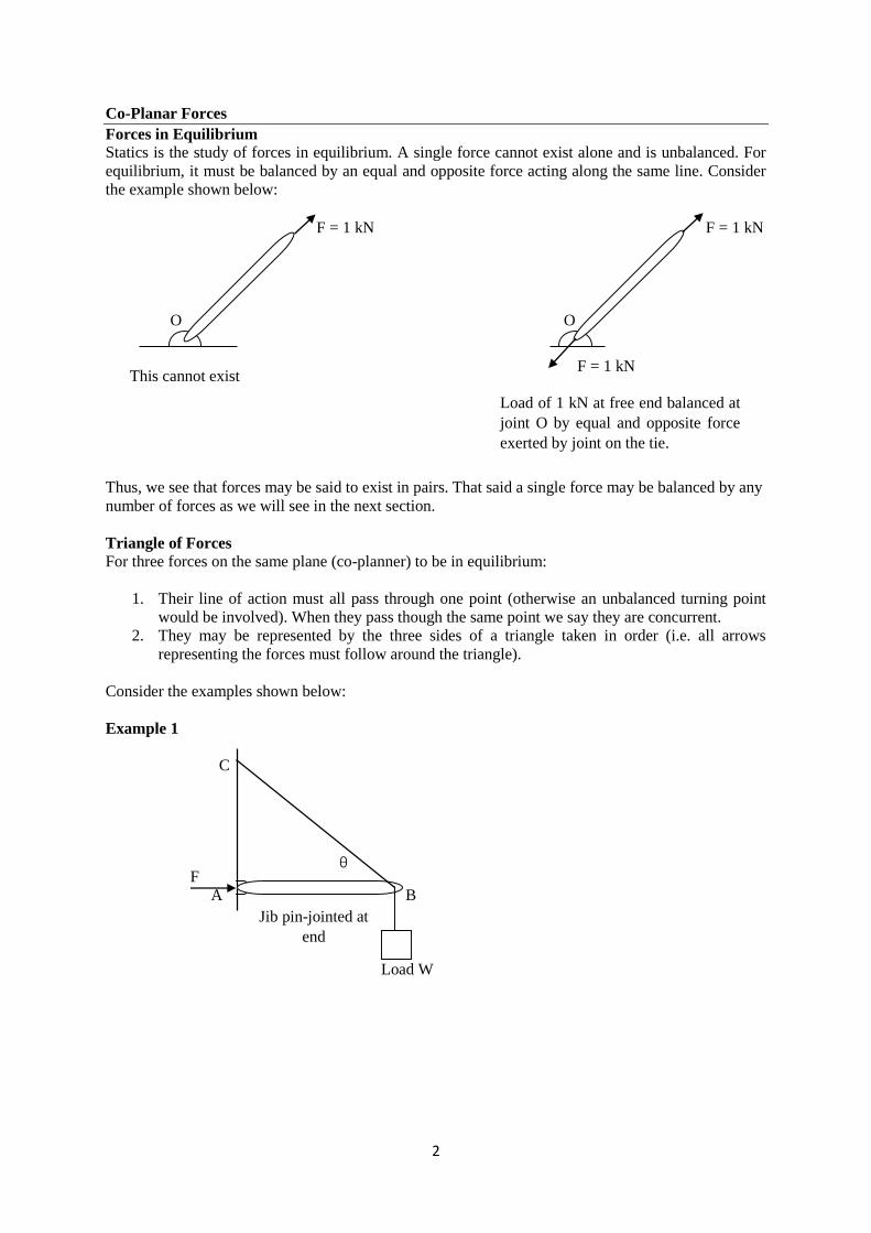
Statics is the study of forces in equilibrium. A single force cannot exist alone and is unbalanced. For
equilibrium, it must be balanced by an equal and opposite force acting along the same line. Consider
the example shown below:
F = 1 kN F = 1 kN
O O
This cannot exist
Thus, we see that forces may be said to exist in pairs. That said a single force may be balanced by any
number of forces as we will see in the next section.
Triangle of Forces
For three forces on the same plane (co-planner) to be in equilibrium:
1. Their line of action must all pass through one point (otherwise an unbalanced turning point
would be involved). When they pass though the same point we say they are concurrent.
2. They may be represented by the three sides of a triangle taken in order (i.e. all arrows
representing the forces must follow around the triangle).
Consider the examples shown below:
Example 1
C
F
A B
Load W
θ
F = 1 kN
Load of 1 kN at free end balanced at
joint O by equal and opposite force
exerted by joint on the tie.
Jib pin-jointed at
end
3
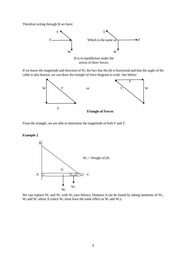
Therefore acting through B we have:
T T
F Which is the same as F
W W
If we know the magnitude and direction of W, the fact that the jib is horizontal and that the angle of the
cable is also known, we can draw the triangle of force diagram to scale. See below:
F
W T or T W
F
From the triangle, we are able to determine the magnitude of both F and T.
Example 2
B
We can replace W1 and W2 with W3 (see below). Distance d can be found by taking moments of W1,
W2 and W3 about A (since W3 must have the same effect as W1 and W2).
B is in equilibrium under the
action of three forces.
Triangle of Forces
C
G
A
W2
W1
W2 = Weight of jib
4
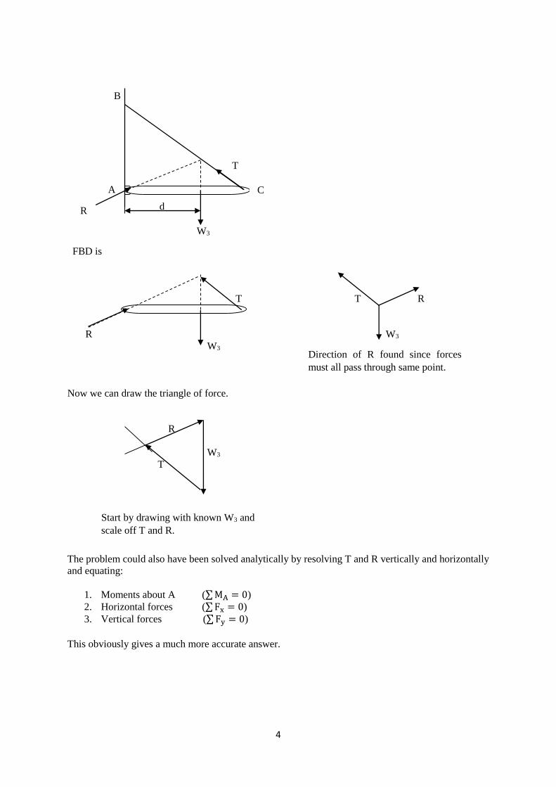
B
R
W3
FBD is
T T R
R W3
W3
Now we can draw the triangle of force.
R
W3
T
The problem could also have been solved analytically by resolving T and R vertically and horizontally
and equating:
1. Moments about A (∑ MA = 0)
2. Horizontal forces (∑ Fx = 0)
3. Vertical forces (∑ Fy = 0)
This obviously gives a much more accurate answer.
d
T
C A
Direction of R found since forces
must all pass through same point.
Start by drawing with known W3 and
scale off T and R.
5
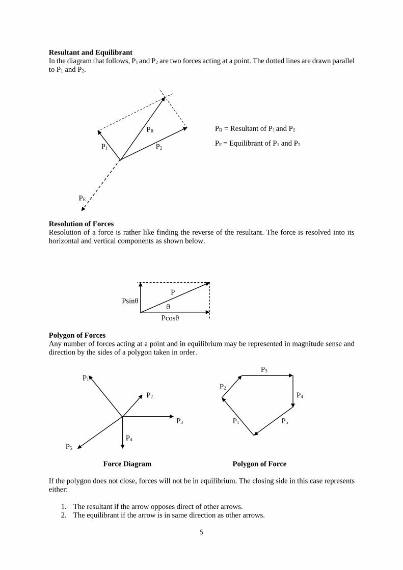
Resultant and Equilibrant
In the diagram that follows, P1 and P2 are two forces acting at a point. The dotted lines are drawn parallel
to P1 and P2.
PR
P1 P2
PE
Resolution of Forces
Resolution of a force is rather like finding the reverse of the resultant. The force is resolved into its
horizontal and vertical components as shown below.
P
Psinθ
Pcosθ
Polygon of Forces
Any number of forces acting at a point and in equilibrium may be represented in magnitude sense and
direction by the sides of a polygon taken in order.
P3
P1
P2
P2 P4
P3 P1 P5
P4
P5
Force Diagram Polygon of Force
If the polygon does not close, forces will not be in equilibrium. The closing side in this case represents
either:
1. The resultant if the arrow opposes direct of other arrows.
2. The equilibrant if the arrow is in same direction as other arrows.
θ
PR = Resultant of P1 and P2
PE = Equilibrant of P1 and P2

6
3. Tutorial Problems
1. A 450 N load is supported by a tied boom as shown. Determine the magnitude of the force C
in the boom and force T the cable.
R
30o Q
40o
450N
O
(C = 395 N; T = 300 N)
2. A block of 200 kg mass is supported by two cables, as shown. Find the magnitude of the forces
in the cables.
A
40o C
B 65o
200 kg
(FBC = 1.306 kN; FAB = 1.842 kN)
3. Two straight bars, AB and BC, are pin connected to a horizontal supporting floor at their lower
ends and to each other at their upper ends, as shown. Applied loads at B are 900 N vertically
and 8100 N horizontally. Compute the magnitude and sense of the forces in the two bars. What
assumptions have you made in coming to these answers?
B
8000 N
8900 N
A 45o 60o C
(FAB = 2.565 kN; FBC = -12.37 kN)
4. Calculate the resultant force on the gusset plate shown below and the angle made by its line of
action with the vertical.

7
(227kN, 72o51’)
5. F and P act along the bars shown in maintaining equilibrium of pin A. Determine the values of
P and F.
(P = -14.76 kN, F = 39 kN)
6. Two weightless bars pinned together as shown, support a load of 35 kN. Determine the force P
and F acting respectively along bars AB and AC that maintain the equilibrium of pin A.
(P = 90.14 kN, F = 64.03 kN)

8
7. For the cylinders shown and assuming smooth contact surfaces, determine reactions at A, B, C,
and D.
(RA = 347.39 kN, RB = 60 kN, RC = 400.85 kN, RD = 347.39 kN)

9
Moment of a Force
A moment is a turning effect of a force.
A moment about a point = Force x perpendicular distance from line of action of force to the point as
shown below:
P
d
Couple
P
p
Total moment of the two forces about any point such as O is:
Mo = P(a + d) − Pd = Pd
What we see is that Mo is independent of ‘a’. Therefore, moment of a couple is the same about any point
in the plane and is the product of one force and the perpendicular distance between the two forces.
Resolution of a Force into a Force and a Couple
Consider the figure given below subjected to a force P at a perpendicular distance d from the pivot.
P
A
d
O
A Moment about A, MA = Pd Nm
O
a
d
A pair of equal and opposite parallel forces which
do not act in the same straight line form a couple.
Arm OA pivoted at O
Force P at right angles to OA

10
P
A
d
P
O
P
P M = Pd
General Conditions for Equilibrium
P1
P5 P2
P4
P3
P1
P5 P2
P4
P3
For equilibrium:
1. The force polygon must close.
2. The algebraic sum of the moments about any point must be zero, i.e. ∑ M = ∑ Pd = 0.
To determine the effect of P on O, two equal and
opposite forces are introduced at O, acting
parallel to existing force P, at A. There is no
change to the system since the two forces at O are
self-cancelling.
The three forces are equivalent to a single force P
at O together with a clockwise couple Pd.
O
O
P1d1
d1 We know that for any point O, each
force can be replaced by an equal force
at O together with a moment about O.
This has been done for the dotted force
P1 which has been replaced by P1 acting
through O and moment P1d about O.
O
Consider now the case of a body acted
on by a number of forces that do not act
through one point (non-concurrent).

11
If the force polygon does not close, then the closing vector is the resultant R and θ gives its angle but
not its position – see below.
To determine the position of the resultant, assume a position on the body and take moments about a
convenient point for the original forces and the resultant.
P1
P5 P2
P4
P3
When solving this type of problem choose point O so that as many lines of action of the forces as
possible pass through it.
Alternatively, resultant R may be found algebraically by resolving all forces in the x and y directions.
Then if X = ∑ Px and Y = ∑ Py it follows that R = √X2 + Y2 and the direction of R will be given by
θ = tan−1 Y
X. The position of R has to be found as described above.
R
R
O
dR
Then RdR = ∑ Pd
If the answer for dR is –ve then R is on the
wrong side of O

12
Worked Example
50 N 30 N
0.5 m
0.3 m
30o
10 N 25N
Take forces upward and to the right as positive and clockwise moments as positive.
Force (N) Vertical component (N) Moment of vertical component about O
(Nm)
50 +50 0
30 +30cos45 = +21.21 -21.21 x 0.5 = -10.606
25 -25sin30 = -12.5 +12.5 x 0.5 = +6.25
10 -10sin60 = -8.66 0
Total Y = +50.05 -4.356
Force (N) Horizontal component (N) Moment of horizontal component about O
(Nm)
50 0 0
30 +30sin45 = +21.21 +21.21 x 0.3 = +6.363
25 +25cos30 = +21.65 0
10 -10cos60 = -5 0
Totals X = +37.86 +6.363
Resultant R = √X2 + Y2 = √37.862 + 50.052 = 62.75 N
θ = tan−1 Y
X= tan−1 50.05
37.86= 52.89°
Total moment = -4.356 + 6.363 = 2.007
This moment is equal to that of the resultant force R about O. If we let d = the perpendicular distance
of the line of action of R from O, then
R x d = 2.007
Therefore, d =2.007
62.75= 0.32 m and is shown below:
R = 62.75 N
0.032 m
You could check out the result for the resultant by drawing the force polygon.
O
30o
60o
45o
For the forces system applied to the piece of
rectangular plate, determine the magnitude,
direction and position of the resultant force.
52.89o

13
Tutorial Problems
1. The link in the diagram below is 1.2m long and pinned at both ends to block free to move in
guides. At the instant shown the link is maintained in equilibrium by a force system in which
the two forces N and Q are unknown. Determine the values of N and Q.
(153.5N, -50N)
2. The figure below shows the tension in the tight and slack side of a rope passing round a pulley
of mass 40kg. Calculate the resultant force on the bearings, and its direction.
(5500N, 23o27’)
3. Diagram shows the forces acting on the handle and dipper of a power shovel. T = thrust in
handle = 250kN, W = weight of handle and dipper = 20kN, F = cutting force at rock face =
242.5kN Determine the rope pull and the angle θ.
(147.5kN, 72o51’)

14
Resultant of Parallel Force Systems
A parallel force system is one in which the lines of action of all forces are parallel. The resultant of such
a system will be parallel to the line of action of the forces in the system. The magnitude, direction, and
sense of the resultant can be determined by the algebraic sum of all the forces. The position of the line
of action of the resultant may be found by the principle of moments, namely, that the moment of the
resultant force is equal to the algebraic sum of the moments of the given force. As an example, consider
the beam shown below loaded with a number of concentrated loads. The beam is pin supported at A
and supported by a roller on a horizontal surface at B. This type of beam is called a simple beam and
the supports are called simple supports.
110N 70N 45N 90N
1 m 2 m 1.6 m
A B
x̅
R
We will assume that acting upward forces are +ve.
R = ∑ Fy = −110 − 70 + 45 − 90 = −225 N
Taking clockwise moment to be -ve
∑ MA = (−70 × 1) + (45 × 3) − (90 × 4.6) = −349Nm
Therefore, R x̅ = ∑ MA
Hence x̅ =−349
−225= 1.55 m
Now let us consider another problem that involves concentrated and uniformly distributed loads (UDL).
A UDL is a load that is spread over a length of beam.
Determine the magnitude and location of the resultant R of the parallel force system shown below.
x̅ R
3 kN 8 kN 2 kN/m
5 m 7 m 4 m 14 m
A B
R = ∑ Fy = − 3 − 8 − (14 × 2)= -39 kN
∑ MA = −(3 × 5) − (8 × 12) − (28 × 23) = −755 kNm
Now Rx̅ = ∑ MA
Therefore x̅ =−755
−39= 19.36 m
15
Equilibrium of Parallel Force Systems
When co-planar parallel force systems are in equilibrium:
∑ F = 0 and ∑ M = 0
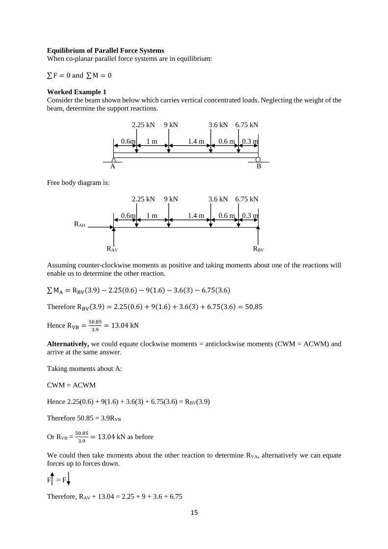
Worked Example 1
Consider the beam shown below which carries vertical concentrated loads. Neglecting the weight of the
beam, determine the support reactions.
2.25 kN 9 kN 3.6 kN 6.75 kN
0.6m 1 m 1.4 m 0.6 m 0.3 m
A B
Free body diagram is:
2.25 kN 9 kN 3.6 kN 6.75 kN
0.6m 1 m 1.4 m 0.6 m 0.3 m
RAH
RAV RBV
Assuming counter-clockwise moments as positive and taking moments about one of the reactions will
enable us to determine the other reaction.
∑ MA = RBV(3.9) − 2.25(0.6) − 9(1.6) − 3.6(3) − 6.75(3.6)
Therefore RBV(3.9) = 2.25(0.6) + 9(1.6) + 3.6(3) + 6.75(3.6) = 50,85
Hence RVB =50.85
3.9= 13.04 kN
Alternatively, we could equate clockwise moments = anticlockwise moments (CWM = ACWM) and
arrive at the same answer.
Taking moments about A:
CWM = ACWM
Hence 2.25(0.6) + 9(1.6) + 3.6(3) + 6.75(3.6) = RBV(3.9)
Therefore 50.85 = 3.9RVB
Or RVB = 50.85
3.9= 13.04 kN as before
We could then take moments about the other reaction to determine RVA, alternatively we can equate
forces up to forces down.
F = F
Therefore, RAV + 13.04 = 2.25 + 9 + 3.6 + 6.75
16
Hence RAV = 8.56 kN
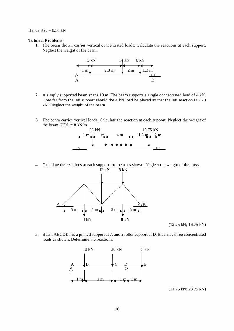
Tutorial Problems
1. The beam shown carries vertical concentrated loads. Calculate the reactions at each support.
Neglect the weight of the beam.
5 kN 14 kN 6 kN
1 m 2.3 m 2 m 1.3 m
A B
2. A simply supported beam spans 10 m. The beam supports a single concentrated load of 4 kN.
How far from the left support should the 4 kN load be placed so that the left reaction is 2.70
kN? Neglect the weight of the beam.
3. The beam carries vertical loads. Calculate the reaction at each support. Neglect the weight of
the beam. UDL = 8 kN/m
36 kN 15.75 kN
1 m 1 m 4 m 1.3 m 2 m
4. Calculate the reactions at each support for the truss shown. Neglect the weight of the truss.
12 kN 5 kN
A B
5 m 5 m 5 m 5 m
4 kN 8 kN
(12.25 kN; 16.75 kN)
5. Beam ABCDE has a pinned support at A and a roller support at D. It carries three concentrated
loads as shown. Determine the reactions.
10 kN 20 kN 5 kN
A B C D E
1 m 2 m 1 m 1 m
(11.25 kN; 23.75 kN)
17
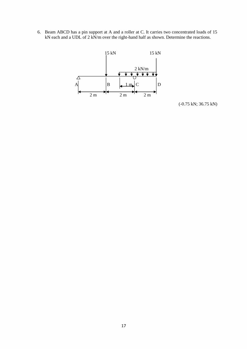
6. Beam ABCD has a pin support at A and a roller at C. It carries two concentrated loads of 15
kN each and a UDL of 2 kN/m over the right-hand half as shown. Determine the reactions.
15 kN 15 kN
2 kN/m
A B 1 m C D
2 m 2 m 2 m
(-0.75 kN; 36.75 kN)

18
Page left blank for your notes