Embed Size (px)
Citation preview
COOLING SYSTEM–COOLING SYSTEM
CO–1
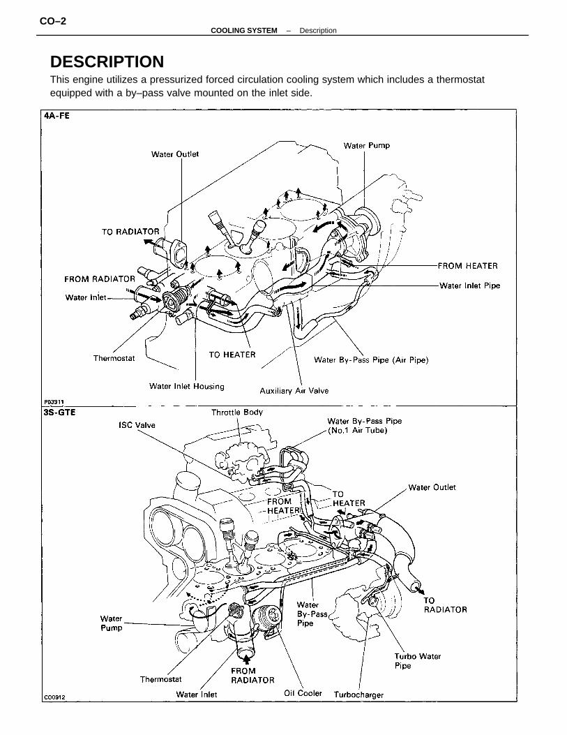
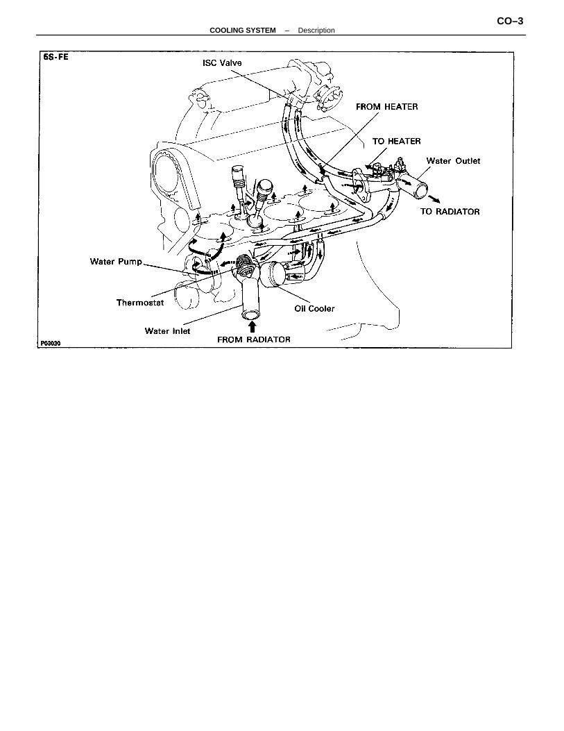
DESCRIPTIONThis engine utilizes a pressurized forced circulation cooling system which includes a thermostatequipped with a by–pass valve mounted on the inlet side.
–COOLING SYSTEM DescriptionCO–2
–COOLING SYSTEM DescriptionCO–3
The cooling system is composed of the water jacket (inside the cylinder block and cylinder head),radiator, water pump, thermostat, electric fan, hoses and other components.Coolant which is heated in the water jacket is pumped to the radiator, through which an electric fanblows air to cool the coolant as it passes through. Coolant which has been cooled is then sent back to theengine by the water pump, where it cools the engine.The water jacket is a network of channels in the shell of the cylinder block and cylinder head throughwhich coolant passes. It is designed to provide adequate cooling of the cylinders and combustion chamberswhich become heated during engine operation.RADIATORThe radiator performs the function of cooling the coolant which has passed through the water jacketand become hot, and it is mounted in the front of the vehicle. The radiator consists of an upper tank andlower tank, and a core which connects the two tanks. The upper tank contains the inlet for coolant fromthe water jacket and the filler inlet. It also has a hose attached through which excess coolant or steamcan flow. The lower tank has an outlet and drain cock for the coolant. The core contains many tubesthrough which coolant flows from the upper tank to the lower tank as well as to cooling fins which radiateheat away from the coolant in the tubes. The air sucked through the radiator by the electric fan, aswell as the wind generated by the vehicle’s travel, passes through the radiator, cooling the coolant.Models with automatic transmission include an automatic transmission fluid cooler built into the lowertank of the radiator. A fan with an electric motor is mounted behind the radiator to assist the flow of airthrough the radiator. The fan operates when the coolant temperature becomes high in order to prevent itfrom becoming too high.RADIATOR CAPThe radiator cap is a pressure type cap which seals the radiator, resulting in pressurization of the radiatoras the coolant expands. The pressurization prevents the coolant from boiling even when the coolanttemperature exceeds 100°C (212°F). A relief valve (pressurization valve) and a vacuum valve (negativepressure valve) are built into the radiator cap. The relief valve opens and lets steam escape through theoverflow pipe when the pressure generated inside the cooling system exceeds the limit (coolant temperature: 110 –120°C (230 – 248°F), pressure; 58.8 – 103.0 kPa (0.6 – 1.05 kgf/cm2, 8.5 – 14.9 psi)). Thevacuum valve opens to alleviate the vacuum which develops in the cooling system after the engine is.stopped and the coolant temperature drops. The valve’s opening allows the coolant in the reservoir tankto return to the cooling system.RESERVOIR TANKThe reservoir tank is used to catch coolant which overflows the cooling system as a result of volumetricexpansion when the coolant is heated. The coolant in the reservoir tank returns to the radiator when thecoolant temperature drops, thus keeping the radiator full at all times and avoiding needless coolant loss.Check the reservoir tank level to learn if the coolant needs to be replenished.WATER PUMPThe water pump is used for forced circulation of coolant through the cooling system. It is mounted onthe front of the cylinder block and driven by a alternator belt (4A–FE) or timing belt (3S–GTE and 5S–FE).THERMOSTATThe thermostat has a wax type by–pass valve and is mounted in the water inlet housing. The thermostatincludes a type of automatic valve operated by fluctuations in the coolant temperature. This valve closeswhen the coolant temperature drops, preventing the circulation of coolant through the engine and thuspermitting the engine to warm up rapidly. The valve opens when the coolant temperature has risen,allowing the circulation of coolant. Wax inside the thermostat expands when heated and contracts whencooled. Heating the wax thus generates pressure which overpowers the force of the spring which keepsthe valve closed, thus opening the valve. When the wax cools, its contraction causes the force of the springto take effect once more, closing the valve. The thermostat in this engine operates at a temperature of 82°C(180°F).
–COOLING SYSTEM DescriptionCO–4
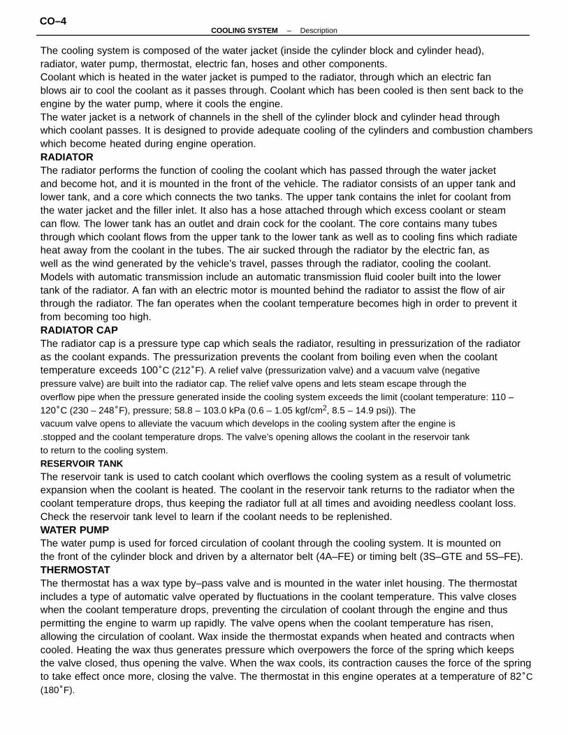
CHECK AND REPLACEMENT OFENGINE COOLANT1. CHECK ENGINE COOLANT LEVEL AT RESERVOIR
TAN KThe coolant level should be between the ”LOW” and”FULL” lines.If low, check for leaks and add coolant up to the ”FULL”line.
Dirt, leaves or insects in radiator or condenser
Hoses, water pump, thermostat housing,
radiator, heater, core plugs or head gasket
leakage
Thermostat faulty
Incorrect ignition timing
Electric cooling system faulty
Radiator hose plugged or rotten
Water pump faulty
Radiator plugged or cap faulty
Cylinder head or block cracked or water
passage clogged
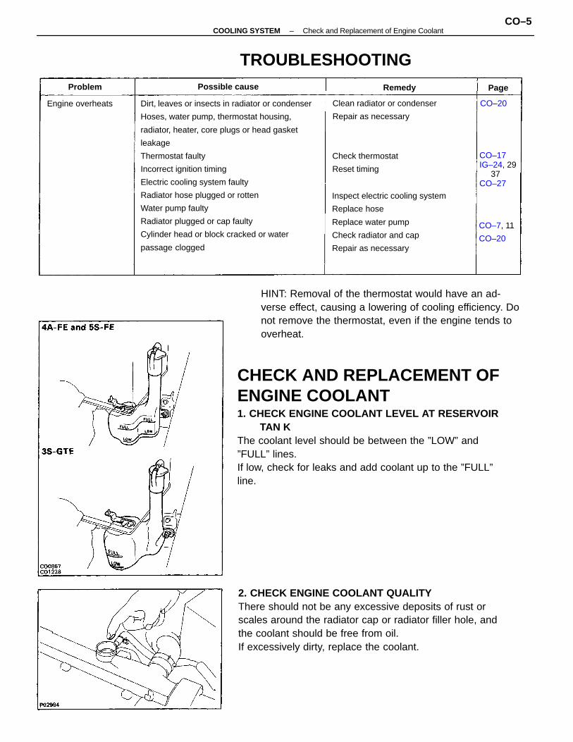
2. CHECK ENGINE COOLANT QUALITYThere should not be any excessive deposits of rust orscales around the radiator cap or radiator filler hole, andthe coolant should be free from oil.If excessively dirty, replace the coolant.
HINT: Removal of the thermostat would have an ad-verse effect, causing a lowering of cooling efficiency. Donot remove the thermostat, even if the engine tends tooverheat.
Inspect electric cooling system
Replace hose
Replace water pump
Check radiator and cap
Repair as necessary
Clean radiator or condenser
Repair as necessary
TROUBLESHOOTING
CO–17IG–24, 29 37CO–27
Check thermostat
Reset timing
CO–7, 11
CO–20
Engine overheats
Possible causeProblem Remedy
CO–20
Page
–COOLING SYSTEM Check and Replacement of Engine CoolantCO–5
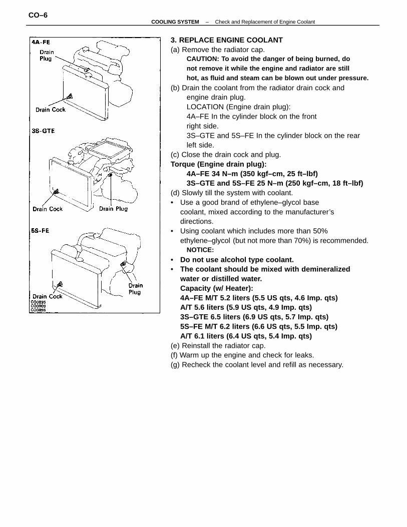
3. REPLACE ENGINE COOLANT(a) Remove the radiator cap.
CAUTION: To avoid the danger of being burned, donot remove it while the engine and radiator are stillhot, as fluid and steam can be blown out under pressure.
(b) Drain the coolant from the radiator drain cock andengine drain plug.LOCATION (Engine drain plug):4A–FE In the cylinder block on the frontright side.3S–GTE and 5S–FE In the cylinder block on the rearleft side.
(c) Close the drain cock and plug.Torque (Engine drain plug):
4A–FE 34 N–m (350 kgf–cm, 25 ft–lbf)3S–GTE and 5S–FE 25 N–m (250 kgf–cm, 18 ft–lbf)
(d) Slowly till the system with coolant.• Use a good brand of ethylene–glycol base
coolant, mixed according to the manufacturer’sdirections.
• Using coolant which includes more than 50%ethylene–glycol (but not more than 70%) is recommended.
NOTICE:
• Do not use alcohol type coolant.• The coolant should be mixed with demineralized
water or distilled water.Capacity (w/ Heater):4A–FE M/T 5.2 liters (5.5 US qts, 4.6 Imp. qts)A/T 5.6 liters (5.9 US qts, 4.9 Imp. qts)3S–GTE 6.5 liters (6.9 US qts, 5.7 Imp. qts)5S–FE M/T 6.2 liters (6.6 US qts, 5.5 Imp. qts)A/T 6.1 liters (6.4 US qts, 5.4 Imp. qts)
(e) Reinstall the radiator cap.(f) Warm up the engine and check for leaks.(g) Recheck the coolant level and refill as necessary.
–COOLING SYSTEM Check and Replacement of Engine CoolantCO–6
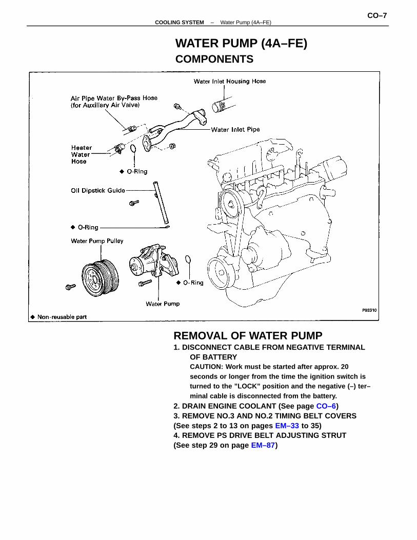
REMOVAL OF WATER PUMP1. DISCONNECT CABLE FROM NEGATIVE TERMINAL
OF BATTERYCAUTION: Work must be started after approx. 20seconds or longer from the time the ignition switch isturned to the ”LOCK” position and the negative (–) ter–minal cable is disconnected from the battery.
2. DRAIN ENGINE COOLANT (See page CO–6)3. REMOVE NO.3 AND NO.2 TIMING BELT COVERS(See steps 2 to 13 on pages EM–33 to 35)4. REMOVE PS DRIVE BELT ADJUSTING STRUT(See step 29 on page EM–87)
WATER PUMP (4A–FE)COMPONENTS
–COOLING SYSTEM Water Pump (4A–FE)CO–7
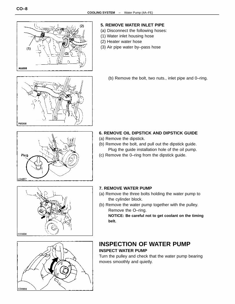
7. REMOVE WATER PUMP(a) Remove the three bolts holding the water pump to
the cylinder block.(b) Remove the water pump together with the pulley.
Remove the O–ring.NOTICE: Be careful not to get coolant on the timingbelt.
6. REMOVE OIL DIPSTICK AND DIPSTICK GUIDE(a) Remove the dipstick.(b) Remove the bolt, and pull out the dipstick guide.
Plug the guide installation hole of the oil pump.(c) Remove the 0–ring from the dipstick guide.
INSPECTION OF WATER PUMPINSPECT WATER PUMPTurn the pulley and check that the water pump bearingmoves smoothly and quietly.
5. REMOVE WATER INLET PIPE(a) Disconnect the following hoses:(1) Water inlet housing hose(2) Heater water hose(3) Air pipe water by–pass hose
(b) Remove the bolt, two nuts., inlet pipe and 0–ring.
–COOLING SYSTEM Water Pump (4A–FE)CO–8
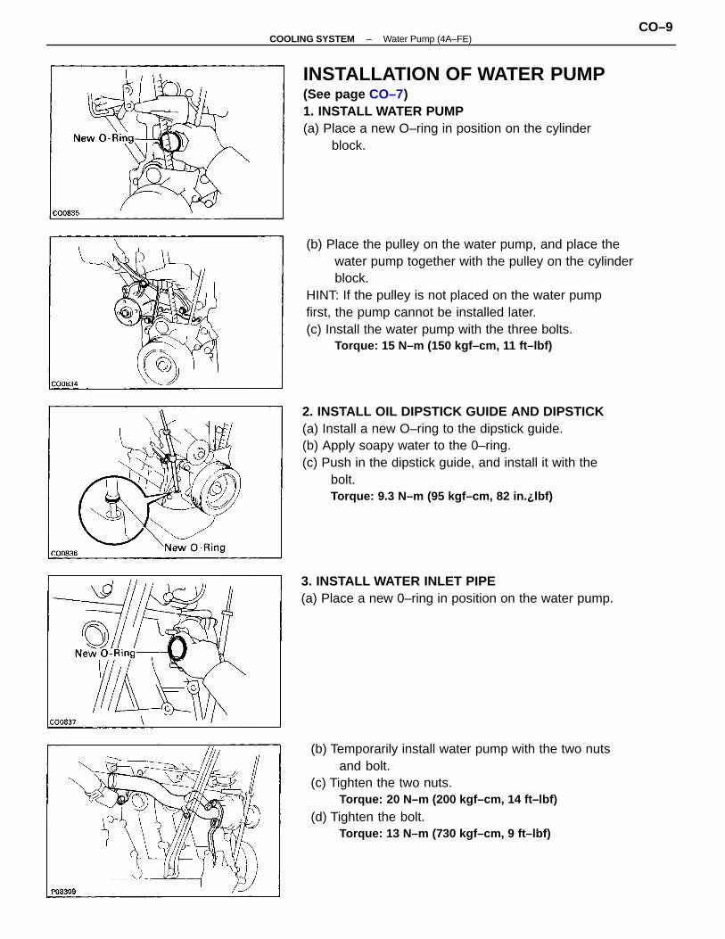
(b) Temporarily install water pump with the two nutsand bolt.
(c) Tighten the two nuts.Torque: 20 N–m (200 kgf–cm, 14 ft–lbf)
(d) Tighten the bolt.Torque: 13 N–m (730 kgf–cm, 9 ft–lbf)
(b) Place the pulley on the water pump, and place thewater pump together with the pulley on the cylinderblock.
HINT: If the pulley is not placed on the water pumpfirst, the pump cannot be installed later.(c) Install the water pump with the three bolts.
Torque: 15 N–m (150 kgf–cm, 11 ft–lbf)
2. INSTALL OIL DIPSTICK GUIDE AND DIPSTICK(a) Install a new O–ring to the dipstick guide.(b) Apply soapy water to the 0–ring.(c) Push in the dipstick guide, and install it with the
bolt.Torque: 9.3 N–m (95 kgf–cm, 82 in.¿lbf)
INSTALLATION OF WATER PUMP(See page CO–7)1. INSTALL WATER PUMP(a) Place a new O–ring in position on the cylinder
block.
3. INSTALL WATER INLET PIPE(a) Place a new 0–ring in position on the water pump.
–COOLING SYSTEM Water Pump (4A–FE)CO–9
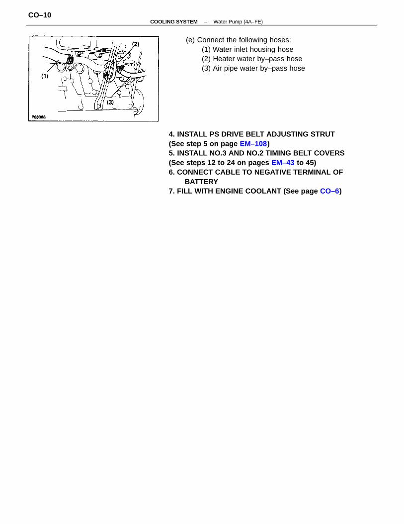
4. INSTALL PS DRIVE BELT ADJUSTING STRUT(See step 5 on page EM–108)5. INSTALL NO.3 AND NO.2 TIMING BELT COVERS(See steps 12 to 24 on pages EM–43 to 45)6. CONNECT CABLE TO NEGATIVE TERMINAL OF
BATTERY7. FILL WITH ENGINE COOLANT (See page CO–6)
(e) Connect the following hoses:(1) Water inlet housing hose(2) Heater water by–pass hose(3) Air pipe water by–pass hose
–COOLING SYSTEM Water Pump (4A–FE)CO–10
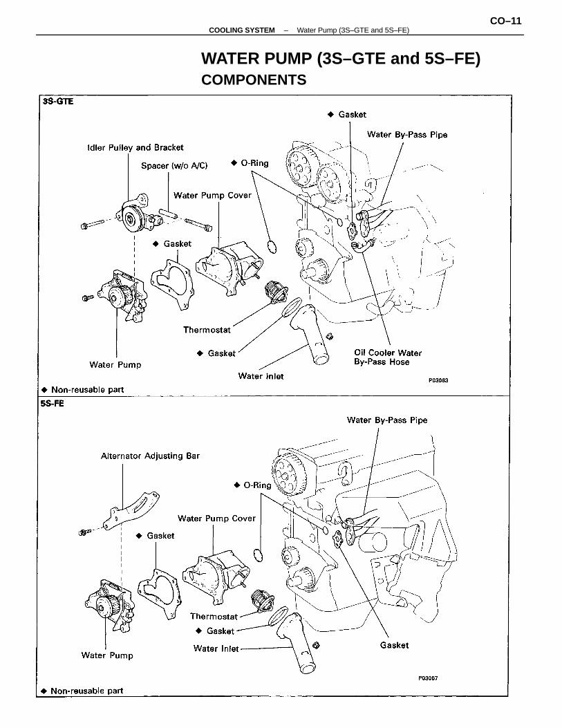
WATER PUMP (3S–GTE and 5S–FE)COMPONENTS
–COOLING SYSTEM Water Pump (3S–GTE and 5S–FE)CO–11
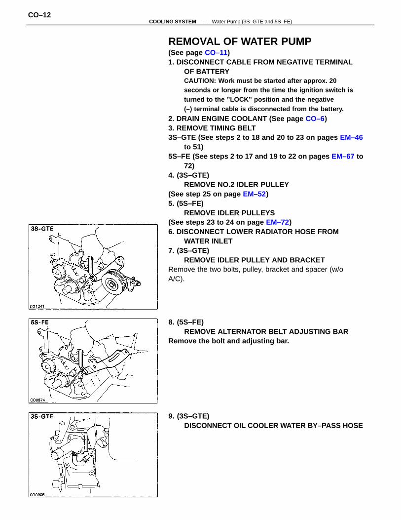
REMOVAL OF WATER PUMP(See page CO–11)1. DISCONNECT CABLE FROM NEGATIVE TERMINAL
OF BATTERYCAUTION: Work must be started after approx. 20seconds or longer from the time the ignition switch isturned to the ”LOCK” position and the negative(–) terminal cable is disconnected from the battery.
2. DRAIN ENGINE COOLANT (See page CO–6)3. REMOVE TIMING BELT3S–GTE (See steps 2 to 18 and 20 to 23 on pages EM–46
to 51)5S–FE (See steps 2 to 17 and 19 to 22 on pages EM–67 to
72)4. (3S–GTE)
REMOVE NO.2 IDLER PULLEY(See step 25 on page EM–52)5. (5S–FE)
REMOVE IDLER PULLEYS(See steps 23 to 24 on page EM–72)6. DISCONNECT LOWER RADIATOR HOSE FROM
WATER INLET7. (3S–GTE)
REMOVE IDLER PULLEY AND BRACKETRemove the two bolts, pulley, bracket and spacer (w/oA/C).
8. (5S–FE)REMOVE ALTERNATOR BELT ADJUSTING BAR
Remove the bolt and adjusting bar.
9. (3S–GTE)DISCONNECT OIL COOLER WATER BY–PASS HOSE
–COOLING SYSTEM Water Pump (3S–GTE and 5S–FE)CO–12

12. REMOVE WATER INLET AND THERMOSTAT FROMWATER PUMP COVER
(a) Remove the two nuts and water inlet from thewater pump.
(b) Remove the thermostat.(c) Remove the gasket from the thermostat.
(b) Remove the three bolts in the sequence shown.(c) Pull out the water pump together with the water
pump cover.(d) Remove the gasket and two 0–rings from the water
pump and water by–pass pipe.
INSPECTION OF WATER PUMPINSPECT WATER PUMPTurn the pulley and check that the water pump bearingmoves smoothly and quietly.
10. REMOVE WATER PUMP AND WATER PUMP COVERASSEMBLY
(a) Remove the two nuts holding the pump to the waterby–pass pipe.
11. SEPARATE WATER PUMP AND WATER PUMPCOVER
Remove the three bolts, water pump and gasket from thewater pump cover.
–COOLING SYSTEM Water Pump (3S–GTE and 5S–FE)CO–13
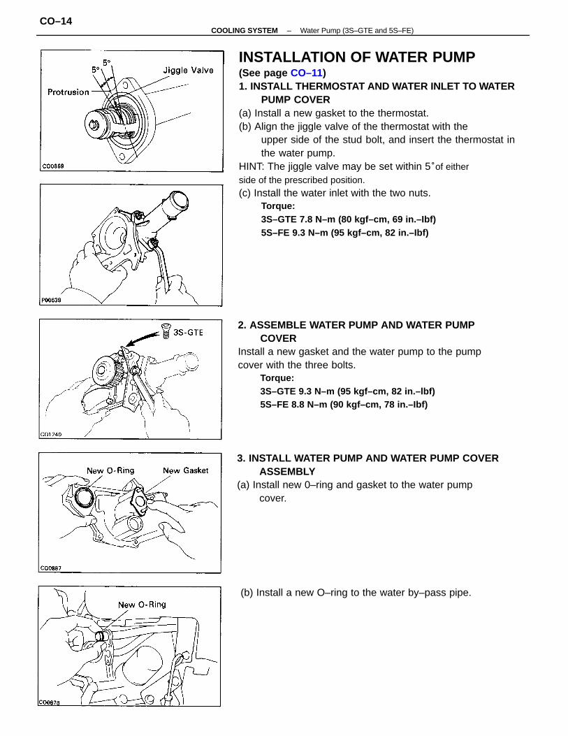
INSTALLATION OF WATER PUMP(See page CO–11)1. INSTALL THERMOSTAT AND WATER INLET TO WATER
PUMP COVER(a) Install a new gasket to the thermostat.(b) Align the jiggle valve of the thermostat with the
upper side of the stud bolt, and insert the thermostat inthe water pump.
HINT: The jiggle valve may be set within 5°of eitherside of the prescribed position.(c) Install the water inlet with the two nuts.
Torque:3S–GTE 7.8 N–m (80 kgf–cm, 69 in.–Ibf)5S–FE 9.3 N–m (95 kgf–cm, 82 in.–Ibf)
2. ASSEMBLE WATER PUMP AND WATER PUMPCOVER
Install a new gasket and the water pump to the pumpcover with the three bolts.
Torque:3S–GTE 9.3 N–m (95 kgf–cm, 82 in.–lbf)5S–FE 8.8 N–m (90 kgf–cm, 78 in.–Ibf)
3. INSTALL WATER PUMP AND WATER PUMP COVERASSEMBLY
(a) Install new 0–ring and gasket to the water pumpcover.
(b) Install a new O–ring to the water by–pass pipe.
–COOLING SYSTEM Water Pump (3S–GTE and 5S–FE)CO–14
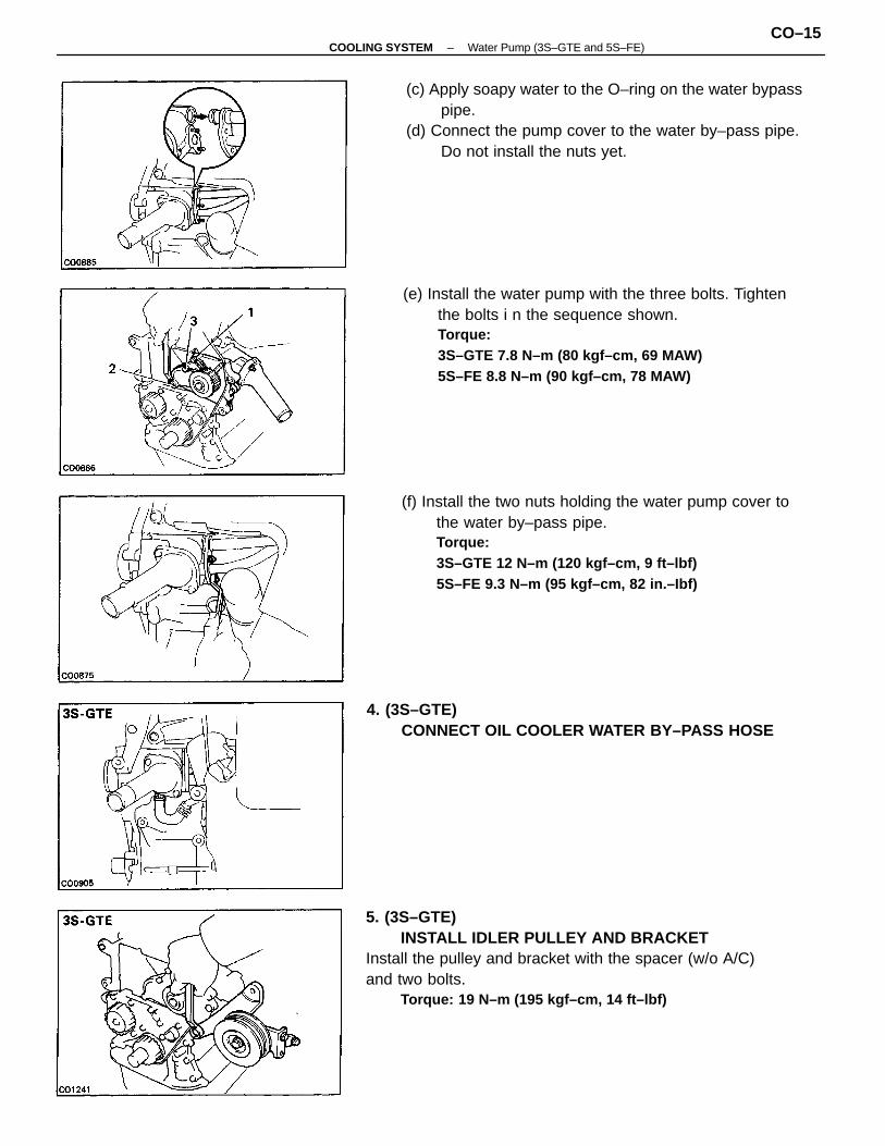
5. (3S–GTE)INSTALL IDLER PULLEY AND BRACKET
Install the pulley and bracket with the spacer (w/o A/C)and two bolts.
Torque: 19 N–m (195 kgf–cm, 14 ft–lbf)
(e) Install the water pump with the three bolts. Tightenthe bolts i n the sequence shown.Torque:3S–GTE 7.8 N–m (80 kgf–cm, 69 MAW)5S–FE 8.8 N–m (90 kgf–cm, 78 MAW)
(f) Install the two nuts holding the water pump cover tothe water by–pass pipe.Torque:3S–GTE 12 N–m (120 kgf–cm, 9 ft–lbf)5S–FE 9.3 N–m (95 kgf–cm, 82 in.–Ibf)
(c) Apply soapy water to the O–ring on the water bypasspipe.
(d) Connect the pump cover to the water by–pass pipe.Do not install the nuts yet.
4. (3S–GTE)CONNECT OIL COOLER WATER BY–PASS HOSE
–COOLING SYSTEM Water Pump (3S–GTE and 5S–FE)CO–15
7. CONNECT LOWER RADIATOR HOSE TO WATERIN LET
8. (3S–GTE)INSTALL NO.2 IDLER PULLEY
(See step 3 on page EM–55)9. (5S–FE)
INSTALL IDLER PULLEYS(See steps 3 and 4 on page EM–75)10. INSTALL TIMING BELT3S–GTE (See steps 5 to 8 and 10 to 30 on pages EM–55
to 61)5S–FE (See steps 5 to 8 and 10 to 27 on pages EM –75to 80)11. CONNECT CABLE TO NEGATIVE TERMINAL OF
BATTERY12. FILL WITH ENGINE COOLANT (See page CO–6)
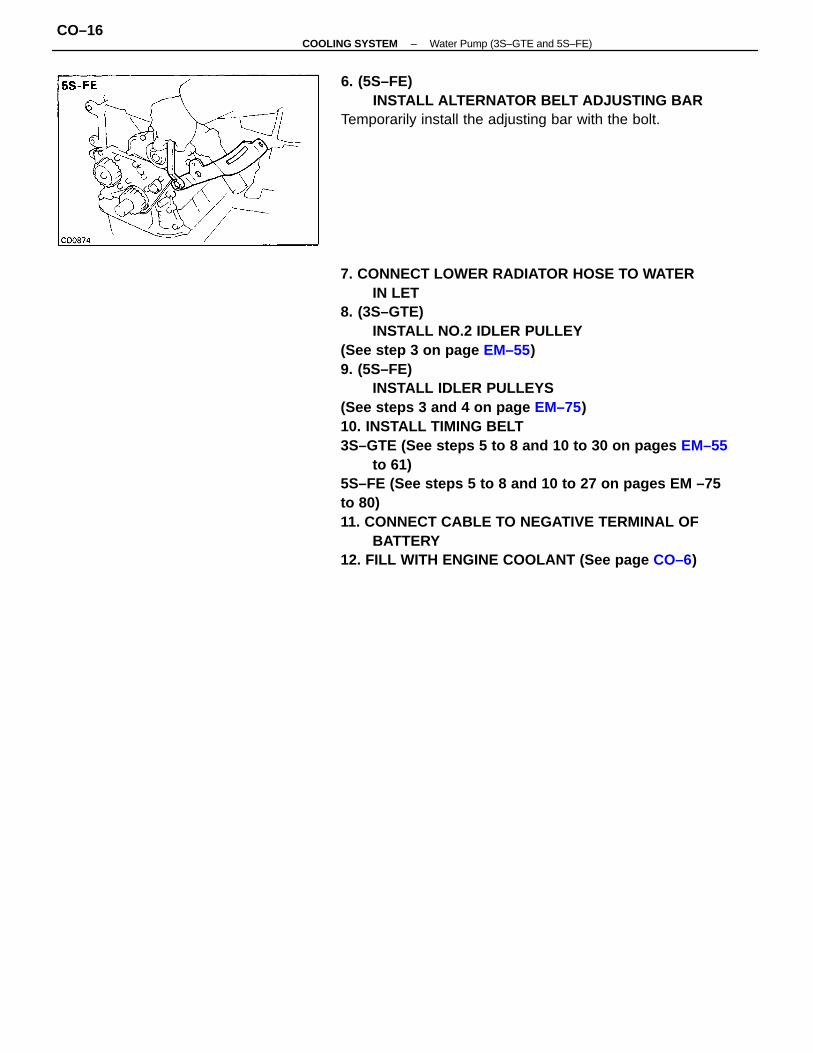
6. (5S–FE)INSTALL ALTERNATOR BELT ADJUSTING BAR
Temporarily install the adjusting bar with the bolt.
–COOLING SYSTEM Water Pump (3S–GTE and 5S–FE)CO–16
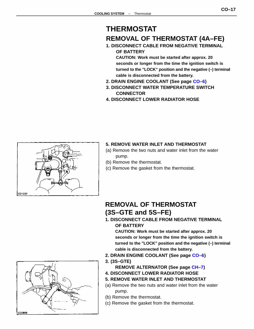
REMOVAL OF THERMOSTAT(3S–GTE and 5S–FE)1. DISCONNECT CABLE FROM NEGATIVE TERMINAL
OF BATTERYCAUTION: Work must be started after approx. 20seconds or longer from the time the ignition switch isturned to the ”LOCK” position and the negative (–) terminalcable is disconnected from the battery.
2. DRAIN ENGINE COOLANT (See page CO–6)3. (3S–GTE)
REMOVE ALTERNATOR (See page CH–7)4. DISCONNECT LOWER RADIATOR HOSE5. REMOVE WATER INLET AND THERMOSTAT(a) Remove the two nuts and water inlet from the water
pump.(b) Remove the thermostat.(c) Remove the gasket from the thermostat.
THERMOSTATREMOVAL OF THERMOSTAT (4A–FE)1. DISCONNECT CABLE FROM NEGATIVE TERMINAL
OF BATTERYCAUTION: Work must be started after approx. 20seconds or longer from the time the ignition switch isturned to the ”LOCK” position and the negative (–) terminalcable is disconnected from the battery.
2. DRAIN ENGINE COOLANT (See page CO–6)3. DISCONNECT WATER TEMPERATURE SWITCH
CONNECTOR4. DISCONNECT LOWER RADIATOR HOSE
5. REMOVE WATER INLET AND THERMOSTAT(a) Remove the two nuts and water inlet from the water
pump.(b) Remove the thermostat.(c) Remove the gasket from the thermostat.
–COOLING SYSTEM ThermostatCO–17
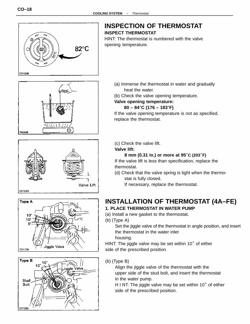
INSTALLATION OF THERMOSTAT (4A–FE)1. PLACE THERMOSTAT IN WATER PUMP(a) Install a new gasket to the thermostat.(b) (Type A)
Set the jiggle valve of the thermostat in angle position, and insertthe thermostat in the water inlethousing.
HINT: The jiggle valve may be set within 10° of eitherside of the prescribed position.
(b) (Type B)Align the jiggle valve of the thermostat with theupper side of the stud bolt, and insert the thermostatin the water pump.H I NT: The jiggle valve may be set within 10° of eitherside of the prescribed position.
(c) Check the valve lift.Valve lift:
8 mm (0.31 in.) or more at 95 °C (203°F)If the valve lift is less than specification, replace thethermostat.(d) Check that the valve spring is tight when the thermo-
stat is fully closed.If necessary, replace the thermostat.
(a) Immerse the thermostat in water and graduallyheat the water.
(b) Check the valve opening temperature.Valve opening temperature:
80 – 84°C (176 – 183°F)If the valve opening temperature is not as specified,replace the thermostat.
INSPECTION OF THERMOSTATINSPECT THERMOSTATHINT: The thermostat is numbered with the valveopening temperature.
–COOLING SYSTEM ThermostatCO–18
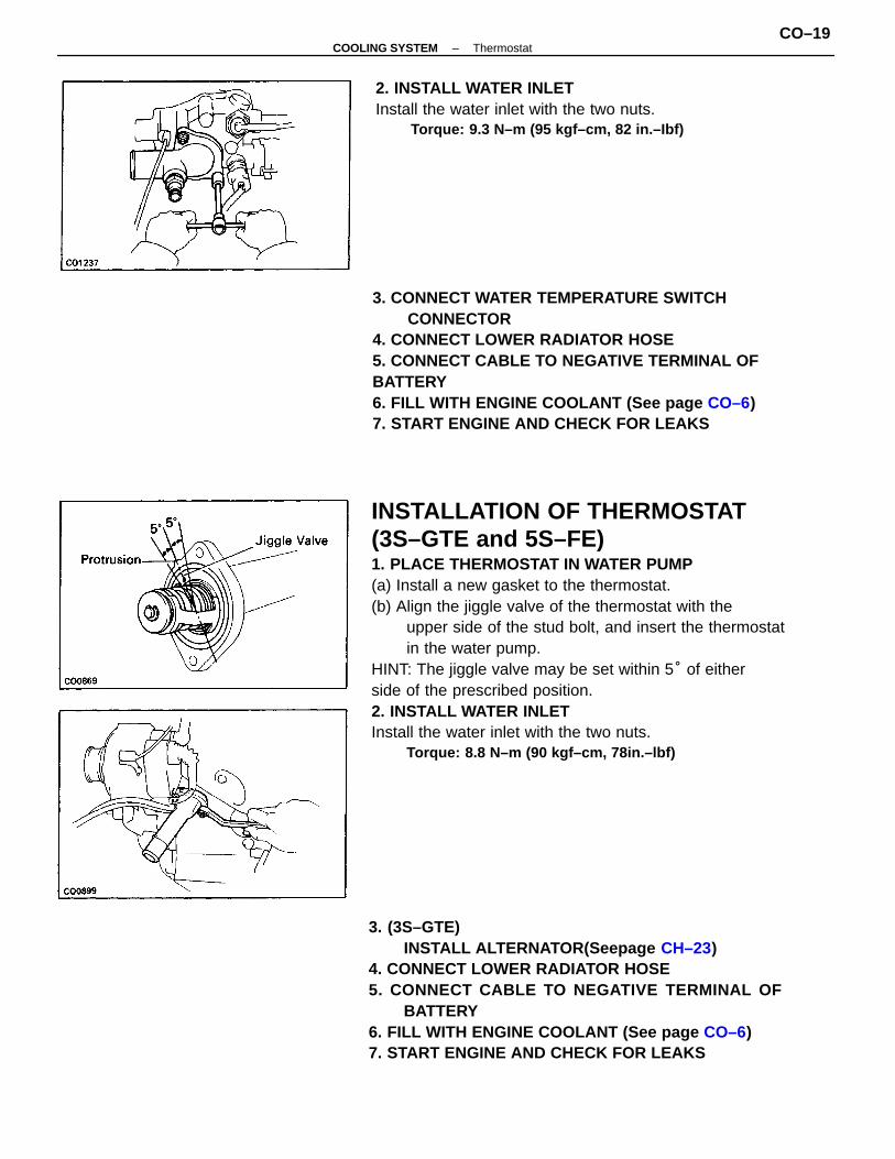
INSTALLATION OF THERMOSTAT(3S–GTE and 5S–FE)1. PLACE THERMOSTAT IN WATER PUMP(a) Install a new gasket to the thermostat.(b) Align the jiggle valve of the thermostat with the
upper side of the stud bolt, and insert the thermostatin the water pump.
HINT: The jiggle valve may be set within 5° of eitherside of the prescribed position.2. INSTALL WATER INLETInstall the water inlet with the two nuts.
Torque: 8.8 N–m (90 kgf–cm, 78in.–lbf)
3. CONNECT WATER TEMPERATURE SWITCHCONNECTOR
4. CONNECT LOWER RADIATOR HOSE5. CONNECT CABLE TO NEGATIVE TERMINAL OFBATTERY6. FILL WITH ENGINE COOLANT (See page CO–6)7. START ENGINE AND CHECK FOR LEAKS
3. (3S–GTE)INSTALL ALTERNATOR(Seepage CH–23)
4. CONNECT LOWER RADIATOR HOSE5. CONNECT CABLE TO NEGATIVE TERMINAL OF
BATTERY6. FILL WITH ENGINE COOLANT (See page CO–6)7. START ENGINE AND CHECK FOR LEAKS
2. INSTALL WATER INLETInstall the water inlet with the two nuts.
Torque: 9.3 N–m (95 kgf–cm, 82 in.–Ibf)
–COOLING SYSTEM ThermostatCO–19
RADIATORCLEANING OF RADIATORUsing water or a steam cleaner, remove any mud and dirtfrom the radiator core.
CAUTION: If using a high pressure type cleaner, becareful not to deform the fins of the radiator core. If thecleaner nozzle pressure is 2,942 – 3,432 kPa (30 – 35kgf/cm2, 427 – 498 psi), keep a distance of at least 40 –50 cm (15.75 – 19.69 in.) between the radiator core andcleaner nozzle.INSPECTION OF RADIATOR
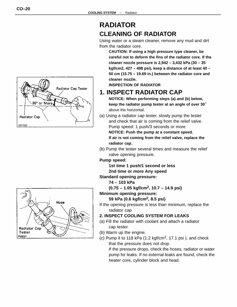
1. INSPECT RADIATOR CAPNOTICE: When performing steps (a) and (b) below,keep the radiator pump tester at an angle of over 30 °
above the horizontal.
(a) Using a radiator cap tester, slowly pump the testerand check that air is coming from the relief valve.Pump speed: 1 push/3 seconds or moreNOTICE: Push the pump at a constant speed.If air is not coming from the relief valve, replace theradiator cap.
(b) Pump the tester several times and measure the reliefvalve opening pressure.
Pump speed:1st time 1 push/1 second or less2nd time or more Any speed
Standard opening pressure:74 – 103 kPa(0.75 – 1.05 kgf/cm 2, 10.7 – 14.9 psi)
Minimum opening pressure:59 kPa (0.6 kgf/cm 2, 8.5 psi)
If the opening pressure is less than minimum, replace theradiator cap.
2. INSPECT COOLING SYSTEM FOR LEAKS(a) Fill the radiator with coolant and attach a radiator
cap tester.(b) Warm up the engine.(c) Pump it to 118 kPa (1.2 kgf/cm2, 17.1 psi ), and check
that the pressure does not drop.If the pressure drops, check the hoses, radiator or waterpump for leaks. If no external leaks are found, check theheater core, cylinder block and head.
–COOLING SYSTEM RadiatorCO–20
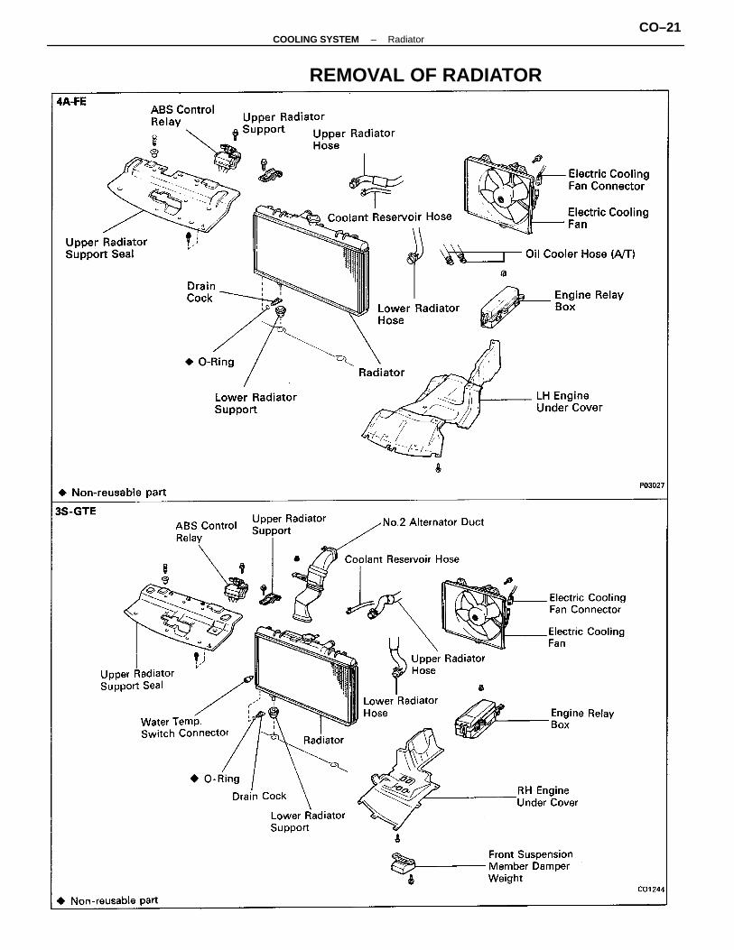
REMOVAL OF RADIATOR
–COOLING SYSTEM RadiatorCO–21
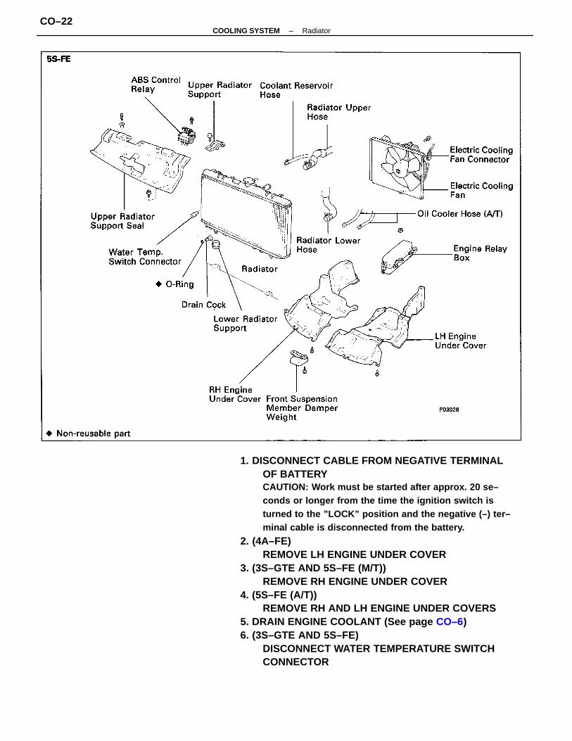
1. DISCONNECT CABLE FROM NEGATIVE TERMINALOF BATTERYCAUTION: Work must be started after approx. 20 se–conds or longer from the time the ignition switch isturned to the ”LOCK” position and the negative (–) ter–minal cable is disconnected from the battery.
2. (4A–FE)REMOVE LH ENGINE UNDER COVER
3. (3S–GTE AND 5S–FE (M/T))REMOVE RH ENGINE UNDER COVER
4. (5S–FE (A/T))REMOVE RH AND LH ENGINE UNDER COVERS
5. DRAIN ENGINE COOLANT (See page CO–6)6. (3S–GTE AND 5S–FE)
DISCONNECT WATER TEMPERATURE SWITCHCONNECTOR
–COOLING SYSTEM RadiatorCO–22
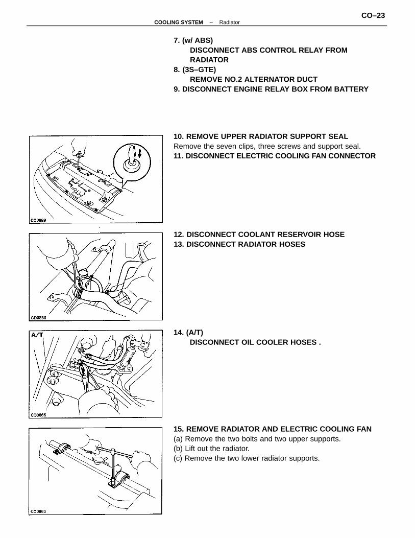
7. (w/ ABS)DISCONNECT ABS CONTROL RELAY FROMRADIATOR
8. (3S–GTE)REMOVE NO.2 ALTERNATOR DUCT
9. DISCONNECT ENGINE RELAY BOX FROM BATTERY
15. REMOVE RADIATOR AND ELECTRIC COOLING FAN(a) Remove the two bolts and two upper supports.(b) Lift out the radiator.(c) Remove the two lower radiator supports.
10. REMOVE UPPER RADIATOR SUPPORT SEALRemove the seven clips, three screws and support seal.11. DISCONNECT ELECTRIC COOLING FAN CONNECTOR
12. DISCONNECT COOLANT RESERVOIR HOSE13. DISCONNECT RADIATOR HOSES
14. (A/T)DISCONNECT OIL COOLER HOSES .
–COOLING SYSTEM RadiatorCO–23
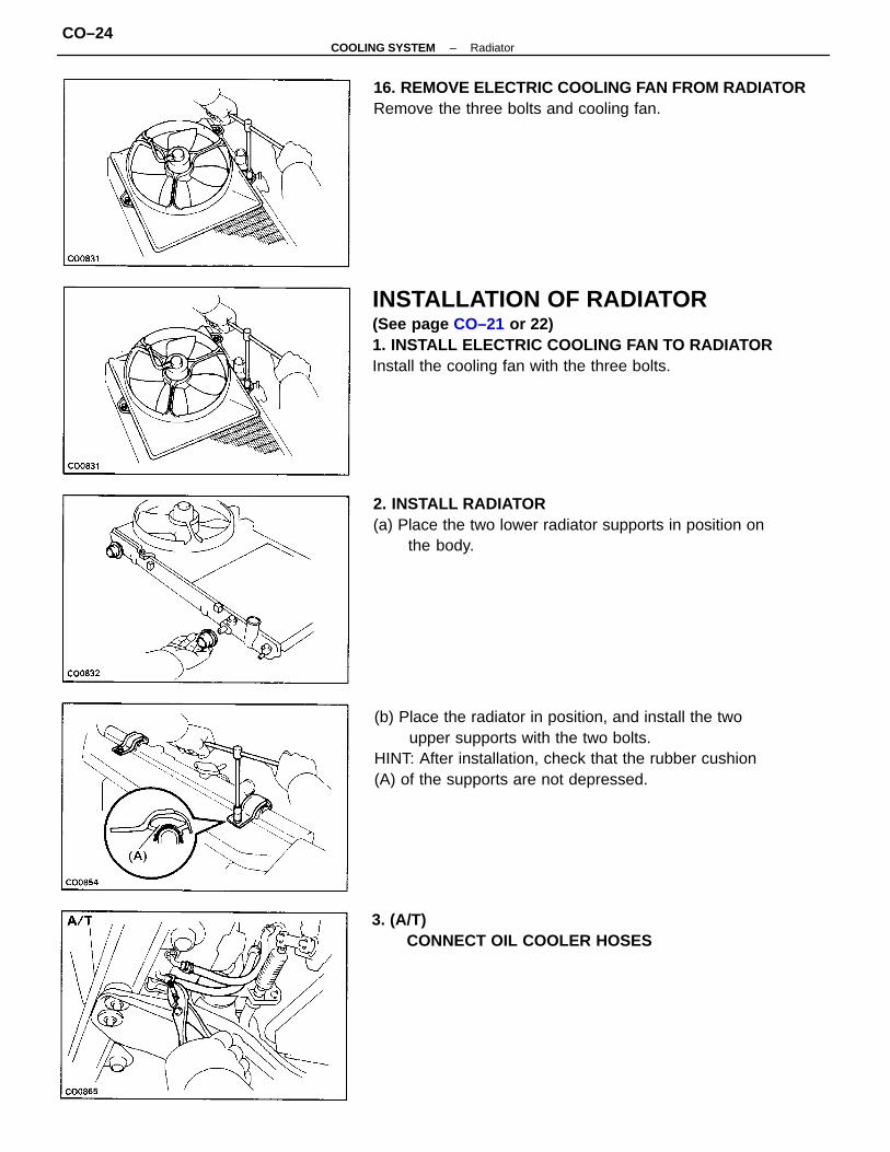
INSTALLATION OF RADIATOR(See page CO–21 or 22)1. INSTALL ELECTRIC COOLING FAN TO RADIATORInstall the cooling fan with the three bolts.
(b) Place the radiator in position, and install the twoupper supports with the two bolts.
HINT: After installation, check that the rubber cushion(A) of the supports are not depressed.
2. INSTALL RADIATOR(a) Place the two lower radiator supports in position on
the body.
16. REMOVE ELECTRIC COOLING FAN FROM RADIATORRemove the three bolts and cooling fan.
3. (A/T)CONNECT OIL COOLER HOSES
–COOLING SYSTEM RadiatorCO–24
8. INSTALL ENGINE RELAY BOX9. (3S–GTE)
INSTALL NO.2 ALTERNATOR AIR DUCT10. (w/ ABS)
INSTALL ABS CONTROL RELAY11. (3S–GTE AND 5S–FE)
CONNECT WATER TEMPERATURE SWITCHCONNECTOR
12. CONNECT CABLE TO NEGATIVE TERMINAL OFBATTERY
13. FILL WITH ENGINE COOLANT (See page CO–6)14. START ENGINE AND CHECK FOR LEAKS15. (A/T)
CHECK AUTOMATIC TRANSMISSION (A/T) FLUIDLEVEL (See page MA–13)NOTICE: Do not overfill.
16. (4A–FE)INSTALL LH ENGINE UNDER COVER
17. (3S–GTE AND 5S–FE (M/T))INSTALL RH ENGINE UNDER COVER
18. (5S–FE (A/T))INSTALL RH AND LH ENGINE UNDER COVERS
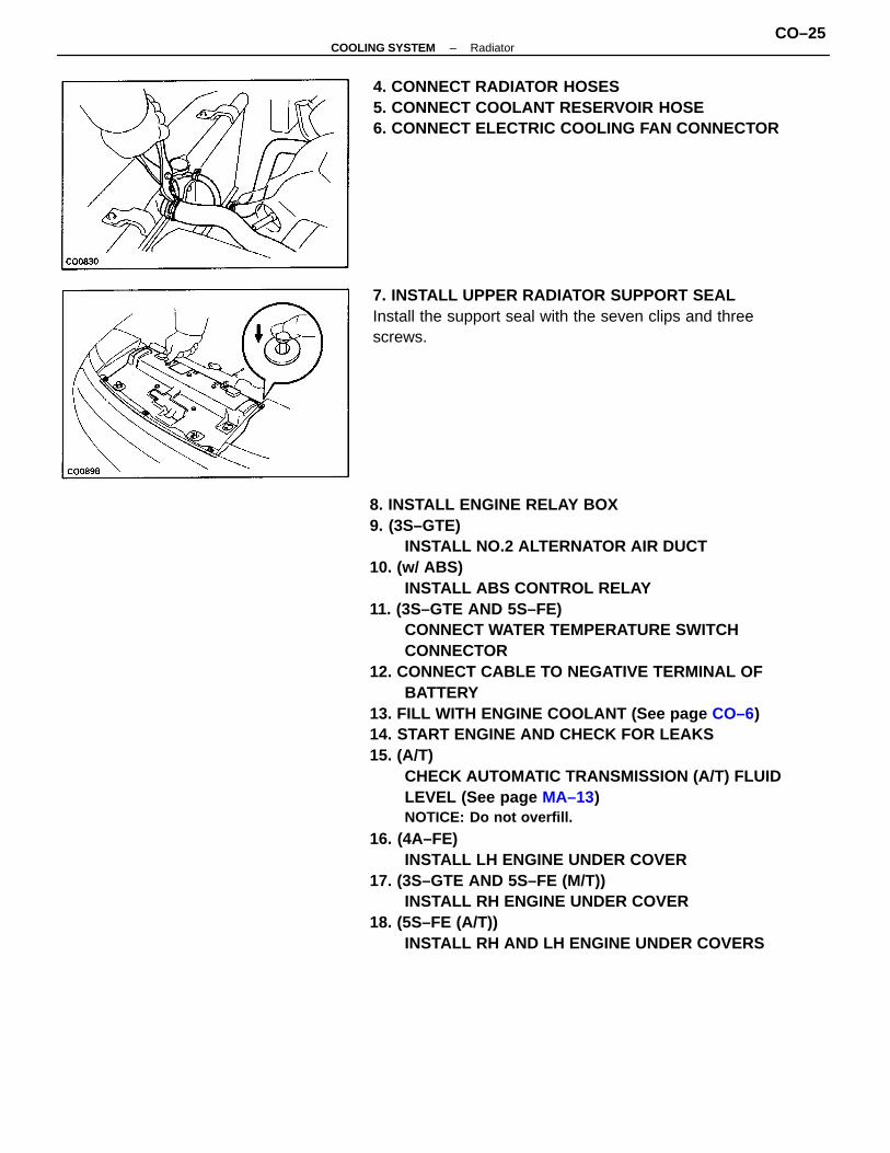
4. CONNECT RADIATOR HOSES5. CONNECT COOLANT RESERVOIR HOSE6. CONNECT ELECTRIC COOLING FAN CONNECTOR
7. INSTALL UPPER RADIATOR SUPPORT SEALInstall the support seal with the seven clips and threescrews.
–COOLING SYSTEM RadiatorCO–25

ELECTRIC COOLING FANSLOCATION OF ELECTRIC COOLING FANCOMPONENTS
–COOLING SYSTEM Electric Cooling FanCO–26
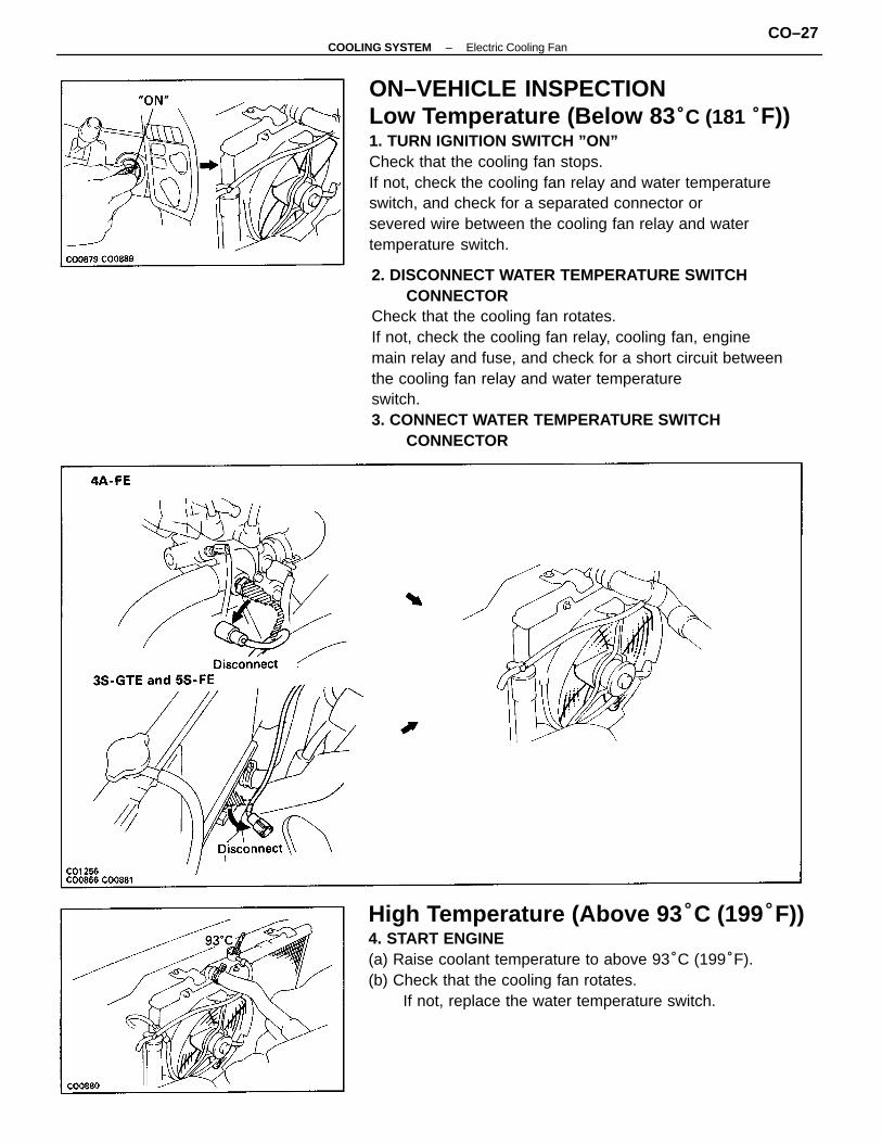
ON–VEHICLE INSPECTIONLow Temperature (Below 83 °C (181 °F))1. TURN IGNITION SWITCH ”ON”Check that the cooling fan stops.If not, check the cooling fan relay and water temperatureswitch, and check for a separated connector orsevered wire between the cooling fan relay and watertemperature switch.
2. DISCONNECT WATER TEMPERATURE SWITCHCONNECTOR
Check that the cooling fan rotates.If not, check the cooling fan relay, cooling fan, enginemain relay and fuse, and check for a short circuit betweenthe cooling fan relay and water temperatureswitch.3. CONNECT WATER TEMPERATURE SWITCH
CONNECTOR
High Temperature (Above 93 °C (199°F))4. START ENGINE(a) Raise coolant temperature to above 93°C (199°F).(b) Check that the cooling fan rotates.
If not, replace the water temperature switch.
–COOLING SYSTEM Electric Cooling FanCO–27
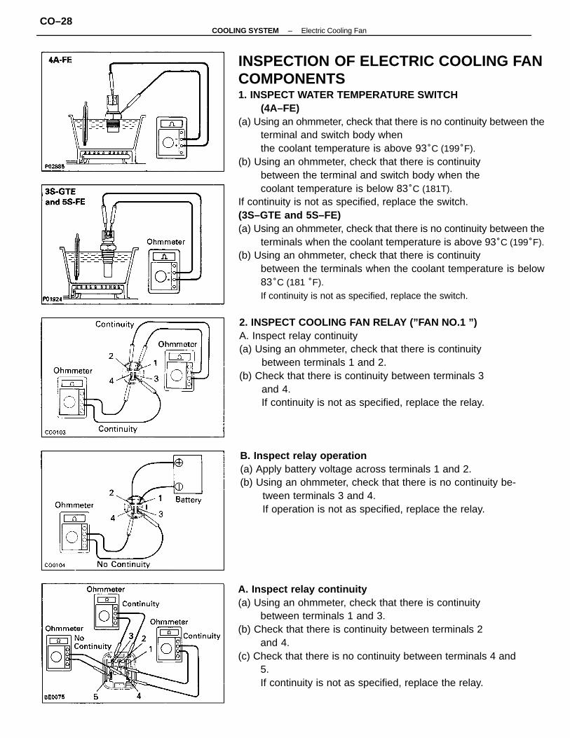
INSPECTION OF ELECTRIC COOLING FANCOMPONENTS1. INSPECT WATER TEMPERATURE SWITCH
(4A–FE)(a) Using an ohmmeter, check that there is no continuity between the
terminal and switch body whenthe coolant temperature is above 93°C (199°F).
(b) Using an ohmmeter, check that there is continuitybetween the terminal and switch body when thecoolant temperature is below 83°C (181T).
If continuity is not as specified, replace the switch.(3S–GTE and 5S–FE)(a) Using an ohmmeter, check that there is no continuity between the
terminals when the coolant temperature is above 93°C (199°F).(b) Using an ohmmeter, check that there is continuity
between the terminals when the coolant temperature is below83°C (181 °F).If continuity is not as specified, replace the switch.
A. Inspect relay continuity(a) Using an ohmmeter, check that there is continuity
between terminals 1 and 3.(b) Check that there is continuity between terminals 2
and 4.(c) Check that there is no continuity between terminals 4 and
5.If continuity is not as specified, replace the relay.
2. INSPECT COOLING FAN RELAY (”FAN NO.1 ”)A. Inspect relay continuity(a) Using an ohmmeter, check that there is continuity
between terminals 1 and 2.(b) Check that there is continuity between terminals 3
and 4.If continuity is not as specified, replace the relay.
B. Inspect relay operation(a) Apply battery voltage across terminals 1 and 2.(b) Using an ohmmeter, check that there is no continuity be-
tween terminals 3 and 4.If operation is not as specified, replace the relay.
–COOLING SYSTEM Electric Cooling FanCO–28
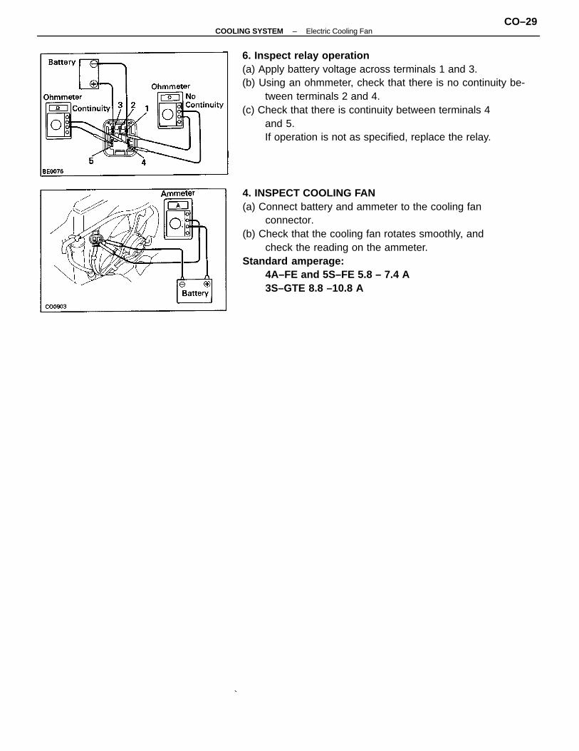
4. INSPECT COOLING FAN(a) Connect battery and ammeter to the cooling fan
connector.(b) Check that the cooling fan rotates smoothly, and
check the reading on the ammeter.Standard amperage:
4A–FE and 5S–FE 5.8 – 7.4 A3S–GTE 8.8 –10.8 A
6. Inspect relay operation(a) Apply battery voltage across terminals 1 and 3.(b) Using an ohmmeter, check that there is no continuity be-
tween terminals 2 and 4.(c) Check that there is continuity between terminals 4
and 5.If operation is not as specified, replace the relay.
–COOLING SYSTEM Electric Cooling FanCO–29
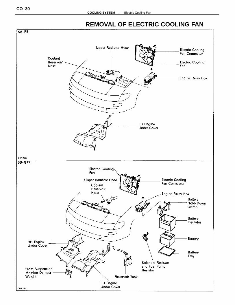
REMOVAL OF ELECTRIC COOLING FAN
–COOLING SYSTEM Electric Cooling FanCO–30
1. DISCONNECT CABLE FROM NEGATIVE TERMINAL OFBATTERYCAUTION:Work must be started after approx.20 sec-onds or longer from the time the ignition switch isturned to the “LOCK”position and the negative(–) ter-minal cable is disconnect from the battery.
2. (4A–FE AND 5S–FE)RENOVE LH ENGINE UNDER COVER
3.(3S–GTE)REMOVE RH AND LH ENGINE UNDER COVERS
4. DRAIN ENGINE COOLANT (See page CO–6)5. DISCONNECT ENGINE RELAY BOX FROM BATTERY6. (3S–GTE)
REMOVE BATTERY7. (3S–GTE)
REMOVE SOLENOID RESISTOR AND FUEL PUMPRESISTOR
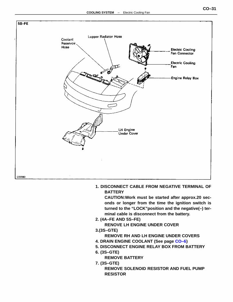
–COOLING SYSTEM Electric Cooling FanCO–31
8. (3S–GTE)REMOVE RESERVOIR TANK
9. (4A–FE AND 5S–FE)DISCONNECT COOLANT RESERVOIR HOSE FROMRADIATOR
10. DISCONNECT UPPER RADIATOR HOSE FROMRADIATOR
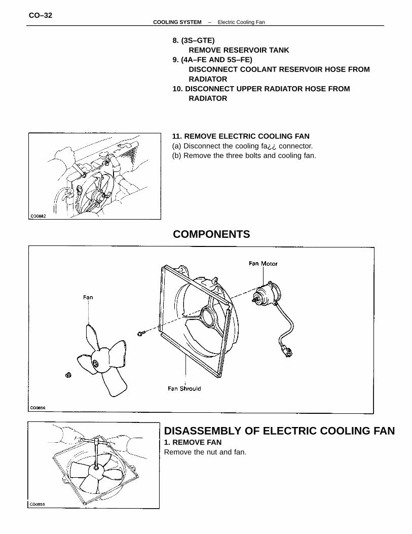
DISASSEMBLY OF ELECTRIC COOLING FAN1. REMOVE FANRemove the nut and fan.
11. REMOVE ELECTRIC COOLING FAN(a) Disconnect the cooling fa¿¿ connector.(b) Remove the three bolts and cooling fan.
COMPONENTS
–COOLING SYSTEM Electric Cooling FanCO–32
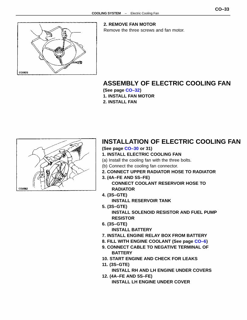
INSTALLATION OF ELECTRIC COOLING FAN(See page CO–30 or 31)1. INSTALL ELECTRIC COOLING FAN(a) Install the cooling fan with the three bolts.(b) Connect the cooling fan connector.2. CONNECT UPPER RADIATOR HOSE TO RADIATOR3. (4A–FE AND 5S–FE)
CONNECT COOLANT RESERVOIR HOSE TORADIATOR
4. (3S–GTE)INSTALL RESERVOIR TANK
5. (3S–GTE)INSTALL SOLENOID RESISTOR AND FUEL PUMPRESISTOR
6. (3S–GTE)INSTALL BATTERY
7. INSTALL ENGINE RELAY BOX FROM BATTERY8. FILL WITH ENGINE COOLANT (See page CO–6)9. CONNECT CABLE TO NEGATIVE TERMINAL OF
BATTERY10. START ENGINE AND CHECK FOR LEAKS11. (3S–GTE)
INSTALL RH AND LH ENGINE UNDER COVERS12. (4A–FE AND 5S–FE)
INSTALL LH ENGINE UNDER COVER
ASSEMBLY OF ELECTRIC COOLING FAN(See page CO–32)1. INSTALL FAN MOTOR2. INSTALL FAN
2. REMOVE FAN MOTORRemove the three screws and fan motor.
–COOLING SYSTEM Electric Cooling FanCO–33