Embed Size (px)
Citation preview
CO2 Capture Research at AETI/ ISGS/ INRS/ UIUC:
Process Development for Minimizing CO2
Desorption Energy and Compression Work
Yongqi Lu1, Massoud Rostam-Abadi1,2
1 Advanced Energy Technology Initiative, Illinois State Geological Survey, Institute of Natural Resource
Sustainability, 2 Department of Civil & Environmental Engineering
UK-US CCS R&D Workshop
Hilton Pittsburgh, PAMay 10 and 12th, 2010
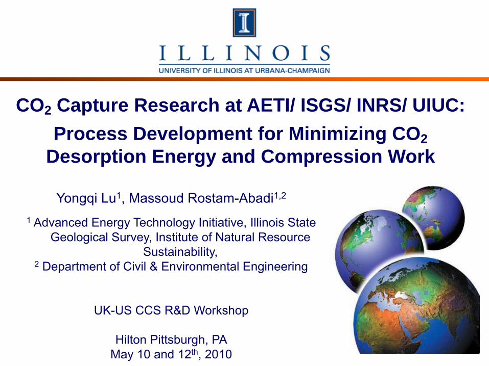
Institute of Natural Resource Sustainability (INRS)>600 scientists and technical support staff; annual budget of $50 million; basic & applied research and service in resource sciences and related subjects
Vice Chancellor for Research
INRS
Illinois Board of Natural Resource Sustainability
Illinois State Water Survey
Illinois Natural History Survey
Illinois Sustainability Technology
Center
Illinois State Geological
Survey
Advanced Energy
Technology Initiative
Water
Environment
Economy
Energy
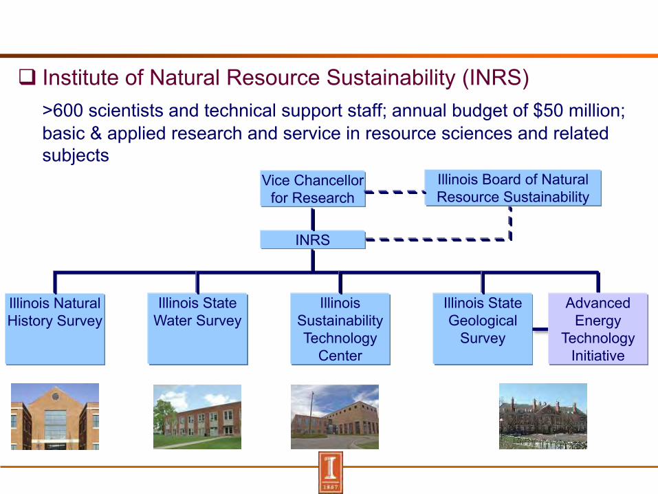
Advanced Energy Technology Initiative (AETI)AETI focuses on development of advanced resource utilization and pollution control technologies
Carbon capture & sequestration
Water-energy Nexus
Air toxics control
Nano science and engineering
Pillars of Economic Growth
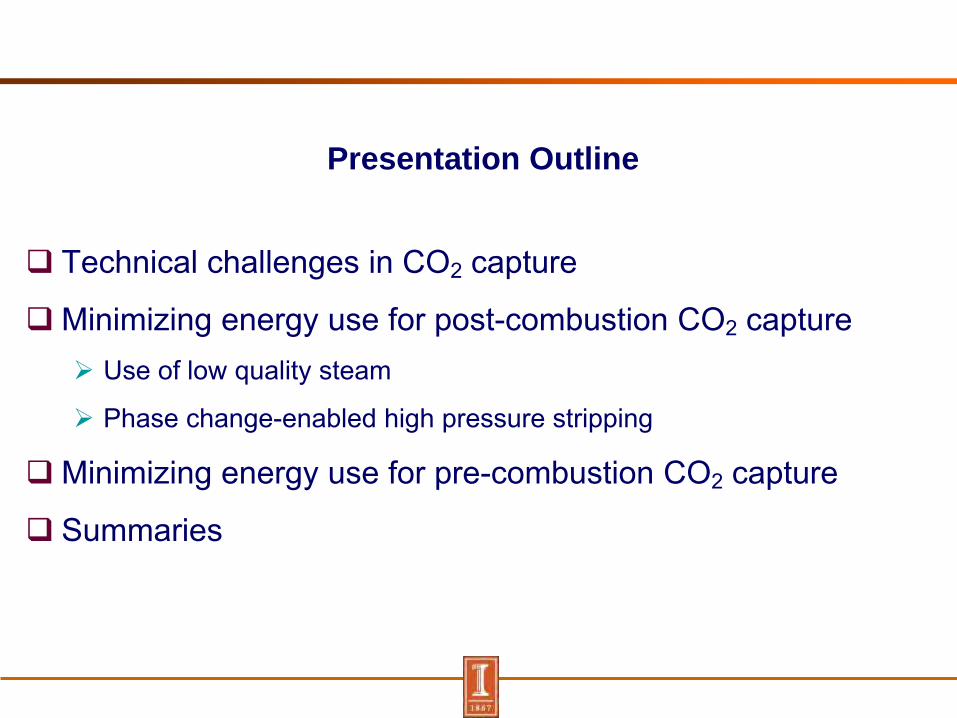
Presentation Outline
Technical challenges in CO2 capture
Minimizing energy use for post-combustion CO2 capture Use of low quality steam
Phase change-enabled high pressure stripping
Minimizing energy use for pre-combustion CO2 capture
Summaries

Cost Breakdown of Baseline MEA Process for CO2 Capture
DOE/NETL baseline MEA process
86% increase in Cost of Electricity (COE)
60% of total cost contributed by parasitic power loss
9%
23%
3%5%
15%
13%
33%
0%
20%
40%
60%
80%
100%
Sh
are
in
CO
E in
cre
ase, %
Steam
Auxiliary power
Compression
power
CO2 TS&M
Compression
capital
CO2 capture
capital
CO2 capture
O&M
Parasitic
power cost,
60%
Capital &
O&M cost,
40%

Parasitic Power Consumption of CO2 Capture Process
Energy use components CO2 desorption (steam use)
Heat of absorption (rxn heat)
Sensible heat (heat for T between CO2-rich and lean solvents)
Stripping heat (water vaporization)
CO2 compression work
Auxiliary work
Work for CDR
Others
Flue gas
Cleaned gas
Solvent
makeup
Lean
Solution
Stripper Absorber
Reboiler
Rich
Solution
Cooler
Cross Heat
Exchanger Steam HLean
HRich
QStripping
Qreaction
QTotal
QSensible= HLean – HRich
CO2
Compressor
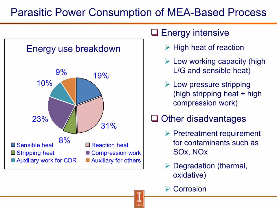
Parasitic Power Consumption of MEA-Based Process
Energy intensive High heat of reaction
Low working capacity (high L/G and sensible heat)
Low pressure stripping (high stripping heat + high compression work)
Other disadvantages Pretreatment requirement
for contaminants such as SOx, NOx
Degradation (thermal, oxidative)
Corrosion
Energy use breakdown
19%
31%
8%
23%
10%9%
Sensible heat Reaction heatStripping heat Compression workAuxiliary work for CDR Auxiliary for others
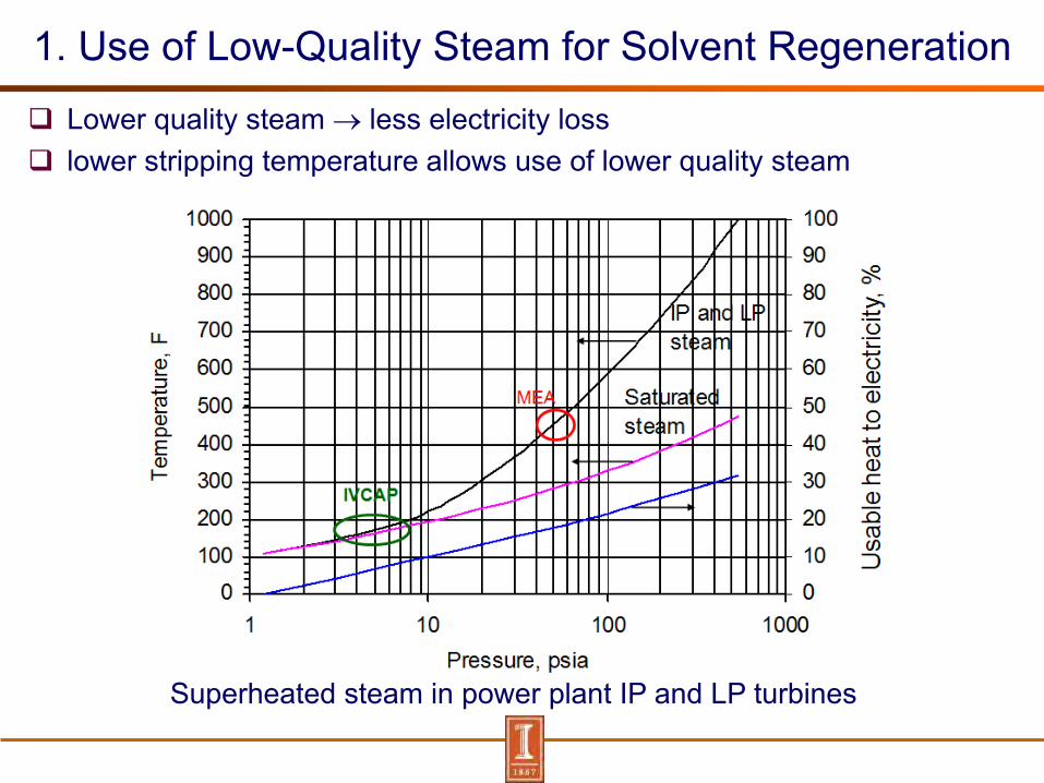
1. Use of Low-Quality Steam for Solvent Regeneration
Lower quality steam less electricity loss lower stripping temperature allows use of lower quality steam
Superheated steam in power plant IP and LP turbines

Integrated Vacuum Carbonate Absorption Process (IVCAP)
Low heat of absorption
K2CO3 (PC) +CO2 +H2O = 2KHCO3
(Hr =600 kJ / kg)
Weak affiliation with CO2favors low T/P stripping
Integration with power plant steam cycle
Vacuum stripping allows use of low quality steam (2-9 pisa vs. ~60 psia for MEA)
Direct introduction of steam into stripper to reduce heat transfer T
Steam
ESP
Air
Generator
Air
Coal
LP Turbine
Multi-Heat Exchangers
Induced Fan
Feed Pump
Condensate Pump
Superheat
Steam
Reheat steam
Cold Reheat
Steam Feedwater
Water Condenser
Boiler
Power Plant with steam cycle
FGD IP
Turbine HP
Turbine
Flue gas
Cleaned gas Water
makeup
Lean
Solution
Stripper Absorber
Vacuum Absorption Process
Reboiler Rich
Solution
Dehydration/
Compression
Cooler
Heat Exchanger
Vacuum Pump
Pump
Pump Pump
Steam
CO2+ water
vapor CO2 stream
Flue
gas
MakeupWater
(CO2/H2O = 1:3)
(2-8 psia
50-70 C)
(40-60 C
1 atm)
(2-8
psia)
Chen, Lu, Rostam-Abadi, Patent Application No. 60/798,489, May 2007

Energy Use Performance of IVCAP
Energy use in CO2 desorption reduced by 20-45% compared to MEA
0102030405060708090
100
2 3 4 8Vacuum, psia
Ele
ctric
ity lo
ss, M
W
Vacuum pumpSteam extraction
MEA
528 MW (gross) plant
0102030405060708090
100
2 3 4 8Vacuum, psia
Ele
ctric
ity lo
ss, M
W
Vacuum pumpSteam extraction
MEA
528 MW (gross) plant
MWPCP W/O
CO2
PCP+ MEA
PCP+ Vacuum
Net output 492.86 358.93 390.07Aux. electricity use 34.74 32.00 33.27Steam extraction 0 89.43 37.81Fan/pump in CO2capture process 0 11.82 12.84CO2 compression 0 35.42 39.65Vacuum pump 0 0 13.96
* A case study based on 3 pisa stripping pressure, 1%wt CO2 lean loading, 20%wt PC, and L/G=1.2 (L/G)min.
Total energy use reduced 20%-30% compared to MEA

Application of Biocatalyst in IVACP PC has a much lower CO2 absorption
rate compared to MEA
Carbonic anhydrase (CA) Most effective catalyst for CO2
hydration Turnover rate =1.4 MM/s at pH
=9 and 25°C
E.Zn H2O H+
E.Zn OH-
E.Zn HCO3- CO2H2O
HCO3- E.Zn H2O H+
E.Zn OH-
E.Zn HCO3- CO2H2O
HCO3-
Molecular structure of CA
Catalytic mechanism
( CO2+H2O = H+ + HCO3- )
3222
32
)()2(
)()1(
COHOHlCO
HCOOHlCO

Activity of CA Biocatalyst in PC Solution Rate into PC increases by 2-20 times at 300 mg/L CA
CA is more effective for PC with higher CO2 loading Presence of SO4
2-, NO3-, Cl- in PC+CA resulted in <11% loss of initial CA activity
0.0E+00
2.0E-04
4.0E-04
6.0E-04
8.0E-04
1.0E-03
1.2E-03
1.4E-03
1.6E-03
1.8E-03
0.0 0.5 1.0 1.5 2.0 2.5 3.0
CO2 partial pressure, psia
CO
2 a
bs
orp
tio
n f
lux
, m
ol/m
2.s
PC with initial 40% conv.+300 mg/l CA
PC with initial 40% conv.+30 mg/l CA
PC with initial 40% conv.
PC with initial 0% conv.+30 mg/l CA
PC with initial 0% conv.
50 oC, 20%wt PC solution

Biocatalyst ImmobilizationAdvantages: Improve enzyme stability Reduce enzyme elution in a
flow system
Support materials Controlled pore glass (CPG,
100nm macro-pore, SA=25m2/g, 200-400 mesh)
Activated carbon, celite, ceramic support materials are currently under investigation
CA enzymes A commercial pure CA used in
developing immobilization methods
Another technical-grade CA currently under investigation

CA Immobilization onto CPG
CPG activation and CPG-CA covalent coupling reactions
CPG cleaningCPG Surface
treatment with silane
toluene solvent
10% γ-aminopropyl triethoxysilane
Washed, air dried & heated
CA-support coupling
2.5%wt glutaraldehyde in Phosphate buffer
CA enzyme
5% HNO3
Surface treatment with
aldehyde
Phosphate buffer
Washed & dried
Washed Filteredwashed & dried
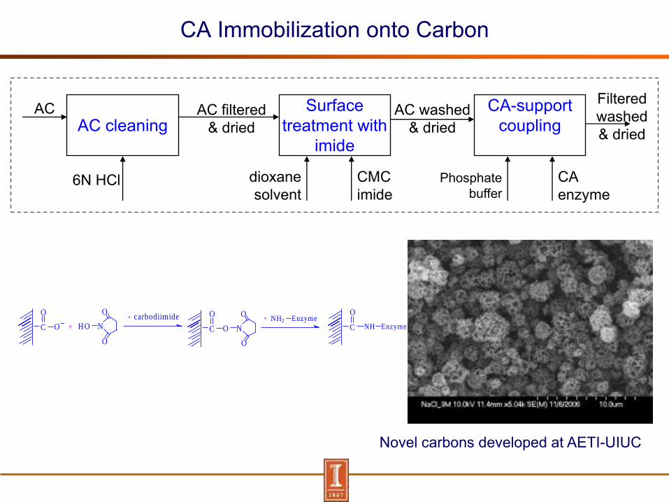
CA Immobilization onto Carbon
Novel carbons developed at AETI-UIUC
AC cleaningAC Surface
treatment with imide
AC filtered & dried
dioxane solvent
CMC imide
AC washed & dried
CA-support coupling
Phosphate buffer
CA enzyme
Filtered washed & dried
6N HCl
OC
O
+ NHO
O
O
OC
O
N
O
O+ EnzymeNH2
C
O
EnzymeNH
+ carbodiimide
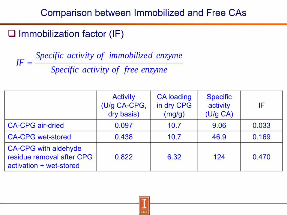
Comparison between Immobilized and Free CAs
Immobilization factor (IF)
Activity(U/g CA-CPG,
dry basis)
CA loading in dry CPG
(mg/g)
Specific activity
(U/g CA)IF
CA-CPG air-dried 0.097 10.7 9.06 0.033CA-CPG wet-stored 0.438 10.7 46.9 0.169CA-CPG with aldehyde residue removal after CPG activation + wet-stored
0.822 6.32 124 0.470
enzymefreeofactivitySpecific
enzymedimmobilizeofactivitySpecificIF
2. Hot Carbonate Absorption Process with High Pressure Stripping Enabled by Crystallization (Hot-CAP)
Absorption at 70-80 C Working capacity of 40%wt PC: 15-40% carbonate-to-bicarbonate conv. Crystallization at room temperature (30C) Stripping of bicarbonate slurry at up to 20-40 atm
Steam from IP Turbine
Hydro
cyclone
Flue gas
Cleaned flue gas
Absorption
column
K2CO3/KHCO3rich Solution
High
Pressure
Stripper
Reboiler
High Pressure
CO2
Crystallization
Tank
SO42-
Removal
Slurry pump
Cross heat
exchanger
Cross heat
exchanger
K2CO3/KHCO3lean Solution
K2CO3/KHCO3slurry
K2CO3/KHCO3lean Solution
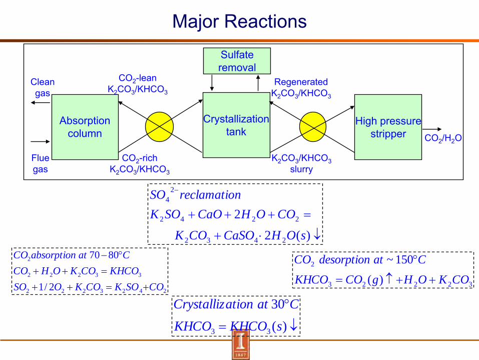
Major Reactions
Absorption column
Crystallization tank
High pressure stripper
Sulfate removal
CO2-rich K2CO3/KHCO3
CO2-lean K2CO3/KHCO3
K2CO3/KHCO3slurry
Regenerated K2CO3/KHCO3
Flue gas
Clean gas
CO2/H2O
2423222
33222
2
2/1
8070
COSOKCOKOSO
KHCOCOKOHCO
CatabsorptionCO
)(
30
33 sKHCOKHCO
CatationCrystalliz
32223
2
)(
150~
COKOHgCOKHCO
CatdesorptionCO
)(2
2
2432
2242
2
4
sOHCaSOCOK
COOHCaOSOK
nreclamatioSO

Technical feasibility
90% CO2 removal Crystallization prevented in absorber High pressure stripping at high T, high
slurry concen., high conv.
Vapor-liquid equilibrium of
CO2K2CO3/KHCO3 (40%wt) systemSolubility of bicarbonate in
carbonate solution
S0
S1
S1
A0
A1
A1
C

Advantages of Hot-CAP Process
High stripping pressure (20-40 atm)
low compression work
low stripping heat (low H2O/CO2 pressure ratio)
Low sensible heat
Comparable working capacity to MEA
Low Cp (1/2)
Low heat of absorption
7-17 kcal/mol CO2 (crystallization heat incld.) vs. 21 kcal/mol for MEA
Kinetics improved by using high concentration PC and high absorption temperature
FGD may be eliminated
No solvent degradation
Less corrosiveness

Energy Use Comparison with MEA
Items MEA Hot-CAP
Energy Consumption CO2 desorption
Heat of absorption (Btu/lbCO2) 825 600Sensible heat (Btu/lbCO2) 600 300Stripping heat (Btu/lbCO2) 270 30
Electricity equivalent (kWh/ kg CO2) 0.28 0.18Compression work (kWh/ kg CO2) 0.09 0.03Total electricity (kWh/kg CO2) 0.37 0.21Operating Degradation (kg MEA/ ton CO2) 2 0FGD Required Y N
Saving of 43% electricity loss compared to MEA
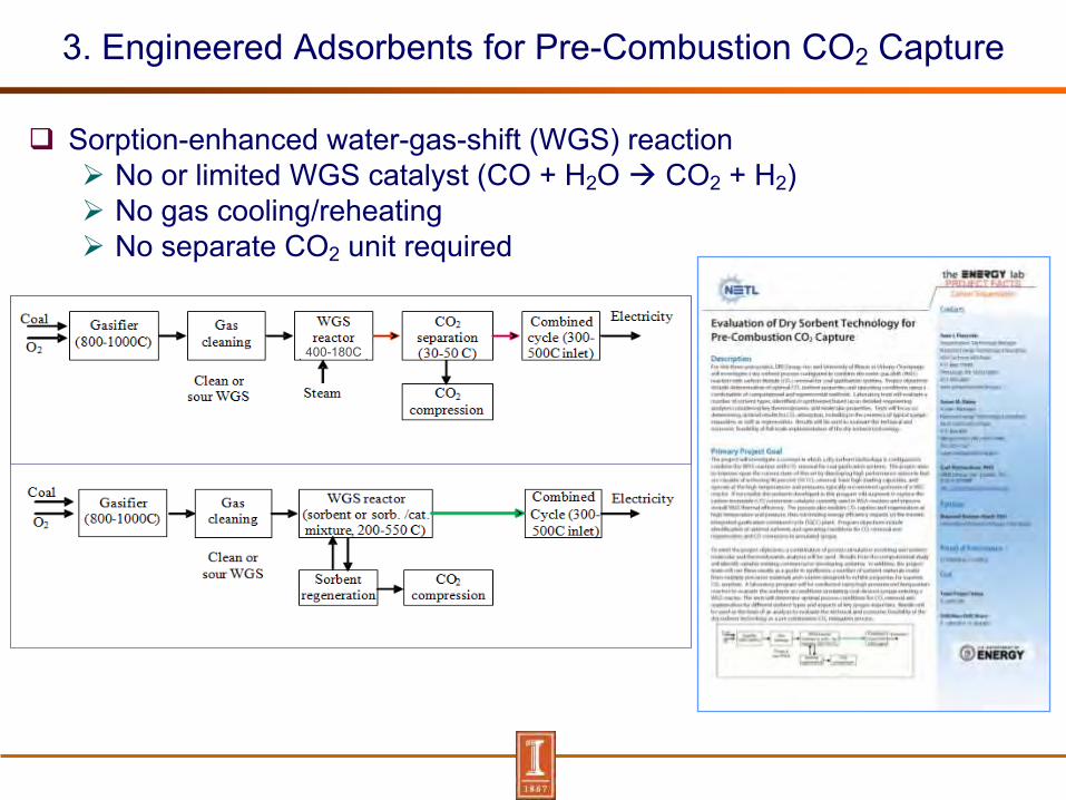
3. Engineered Adsorbents for Pre-Combustion CO2 Capture
Sorption-enhanced water-gas-shift (WGS) reaction No or limited WGS catalyst (CO + H2O CO2 + H2) No gas cooling/reheating No separate CO2 unit required
400-180C

Engineered Adsorbents for Pre-Combustion CO2 Capture
Scope of Work Molecular and process simulation modeling to optimize sorbent
properties
Synthesis/characterization of sorbents
Sorbent evaluation at WGS conditions using a high pressure and temperature reactor (HPTR) and high pressure TGA
Techno-economic analysis and scale-up
Support
CO
H2O
Catalyst
H2
CO2
Sorbent
CO2

Summaries
Use of low quality steam provides one option for reducing solvent regeneration energy
Compression work can be minimized by high pressure stripping
Improving process reversibility and heat integration can further improve energy efficiency
Availability of catalysts to accelerate CO2 absorption into a solvent could enable applications of absorption processes that otherwise are limited by slow rates of reaction

Thank You!
Questions or Comments?
Contact Information:
Yongqi Lu, Massoud [email protected]
http://www.inrs.illinois.edu/http://www.isgs.illinois.edu/
http://sequestration.org/