Embed Size (px)
Citation preview
CO2-Pro CV User’s Manual
Pro-Oceanus Systems Inc. 80 Pleasant Street, Bridgewater Nova Scotia, CANADA, B4V 1N1
Phone: (902) 530-3550 Fax: (902) 530-3551
www.pro-oceanus.com April 5, 2016
Revision 3.0.3
Pro-‐Oceanus CO2-‐Pro CV User’s Manual
Revision 3.0.3 2016-‐04-‐05 2
Table of Contents
1.0 Introduction ....................................................................................................................................... 3 2.0 Instrument Setup .............................................................................................................................. 4
2.1 Instrument Checklist ................................................................................................................... 4 2.2 Optional Accessories .................................................................................................................. 5 2.3 Gas Concentration Ranges Available ..................................................................................... 6 2.4 Customized Units ......................................................................................................................... 6
3.0 Instrument Setup and User Interface ............................................................................................. 7 3.1 Instrument Setup .......................................................................................................................... 7 3.2 Sensor Communication and User Interface .......................................................................... 8 3.2.1 User Interface .............................................................................................................................. 9 3.2.2 Logger / Controller Menu ......................................................................................................... 11 3.2.3 Sample Setup Menu ................................................................................................................. 14 3.2.4 Polling Data ................................................................................................................................ 19 3.3 Data Output .................................................................................................................................. 20
4.0 CO2 Measurement ........................................................................................................................... 21 4.1 Equilibration dynamics and instrument response time ................................................... 21 4.2 Infrared detection method ........................................................................................................ 23 4.3 Partial pressure of CO2, pCO2 ................................................................................................. 24 4.4 CO2 solubility and dissolved phase concentration ........................................................... 25
5.0 Instrument Deployment ................................................................................................................. 27 5.1 Pre-deployment set-up ............................................................................................................. 27 5.2 Recommended Deployment Practices .................................................................................. 27 5.3 Integration Options .................................................................................................................... 28 5.4 Power Budgets ............................................................................................................................ 28
6.0 Care and Maintenance ................................................................................................................... 31 6.1 Instrument Housing and Bulkhead Connectors ................................................................. 31 6.2 Replacing the CO2 Absorbent ................................................................................................. 31 6.3 Internal Clock Battery Replacement ...................................................................................... 34 6.4 Cleaning and Replacing the Interface ................................................................................... 35 6.5 Detector Re-Calibration ............................................................................................................ 37
7.0 Troubleshooting ............................................................................................................................. 38 8.0 Warranty ........................................................................................................................................... 39 Appendix A: Sensor Specifications ................................................................................................... 40 Appendix B: Instrument Pin Out ........................................................................................................ 41 Appendix C: Pass-through Mode commands .................................................................................. 42 Appendix D: Material Safety Data Sheets ......................................................................................... 47
Pro-‐Oceanus CO2-‐Pro CV User’s Manual
Revision 3.0.3 2016-‐04-‐05 3
1.0 Introduction The CO2-Pro CV is an accurate in situ submersible pCO2 sensor designed for use by scientists for applications in aquatic sciences and the environment where long-term, stable measurements of pCO2 are required. The sensor can be deployed in either fresh- or sea-water. The Pro CV instrument builds on the original CO2-Pro design to allow for deeper deployments and faster response.
The CO2-Pro CV operates through rapid diffusion of dissolved gases from liquids through a supported semi-permeable membrane to a non-dispersive infrared detector (NDIR). The NDIR sensor is factory calibrated using trace gases from the NOAA ESRL GMD Central Calibration Laboratory (http://www.esrl.noaa.gov/gmd/ccl/).
Long-term signal stability is achieved through an automatic zero compensation function that periodically removes CO2 from the system and records a new zero CO2 baseline value.
Pro-‐Oceanus CO2-‐Pro CV User’s Manual
Revision 3.0.3 2016-‐04-‐05 4
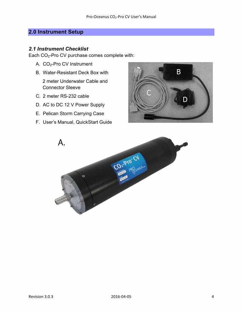
2.0 Instrument Setup 2.1 Instrument Checklist Each CO2-Pro CV purchase comes complete with:
A. CO2-Pro CV Instrument
B. Water-Resistant Deck Box with
2 meter Underwater Cable and Connector Sleeve
C. 2 meter RS-232 cable
D. AC to DC 12 V Power Supply
E. Pelican Storm Carrying Case
F. User’s Manual, QuickStart Guide
Pro-‐Oceanus CO2-‐Pro CV User’s Manual
Revision 3.0.3 2016-‐04-‐05 5
2.2 Optional Accessories
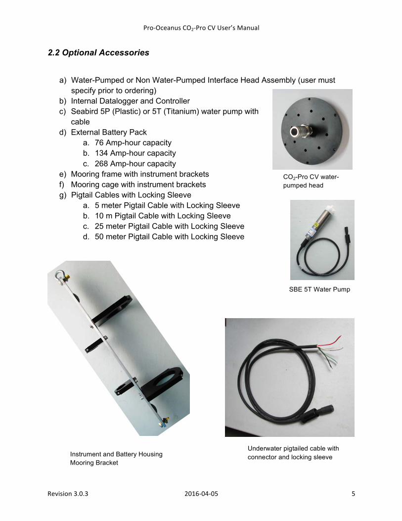
a) Water-Pumped or Non Water-Pumped Interface Head Assembly (user must specify prior to ordering)
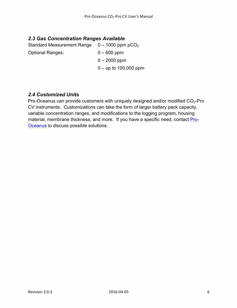
b) Internal Datalogger and Controller c) Seabird 5P (Plastic) or 5T (Titanium) water pump with
cable d) External Battery Pack
a. 76 Amp-hour capacity b. 134 Amp-hour capacity c. 268 Amp-hour capacity
e) Mooring frame with instrument brackets f) Mooring cage with instrument brackets g) Pigtail Cables with Locking Sleeve
a. 5 meter Pigtail Cable with Locking Sleeve b. 10 m Pigtail Cable with Locking Sleeve c. 25 meter Pigtail Cable with Locking Sleeve d. 50 meter Pigtail Cable with Locking Sleeve
CO2-Pro CV water-pumped head
SBE 5T Water Pump
Instrument and Battery Housing Mooring Bracket
Underwater pigtailed cable with connector and locking sleeve
Pro-‐Oceanus CO2-‐Pro CV User’s Manual
Revision 3.0.3 2016-‐04-‐05 6
2.3 Gas Concentration Ranges Available Standard Measurement Range 0 – 1000 ppm pCO2 Optional Ranges: 0 – 600 ppm 0 – 2000 ppm 0 – up to 100,000 ppm
2.4 Customized Units Pro-Oceanus can provide customers with uniquely designed and/or modified CO2-Pro CV instruments. Customizations can take the form of larger battery pack capacity, variable concentration ranges, and modifications to the logging program, housing material, membrane thickness, and more. If you have a specific need, contact Pro-Oceanus to discuss possible solutions.
Pro-‐Oceanus CO2-‐Pro CV User’s Manual
Revision 3.0.3 2016-‐04-‐05 7
3.0 Instrument Setup and User Interface 3.1 Instrument Setup The CO2-Pro CV employs a flat semi-permeable membrane interface for equilibration of headspace gas with surrounding water. A water-pumped head with water pump is strongly recommended to provide faster detector equilibration and improved anti-fouling of the semi-permeable membrane.
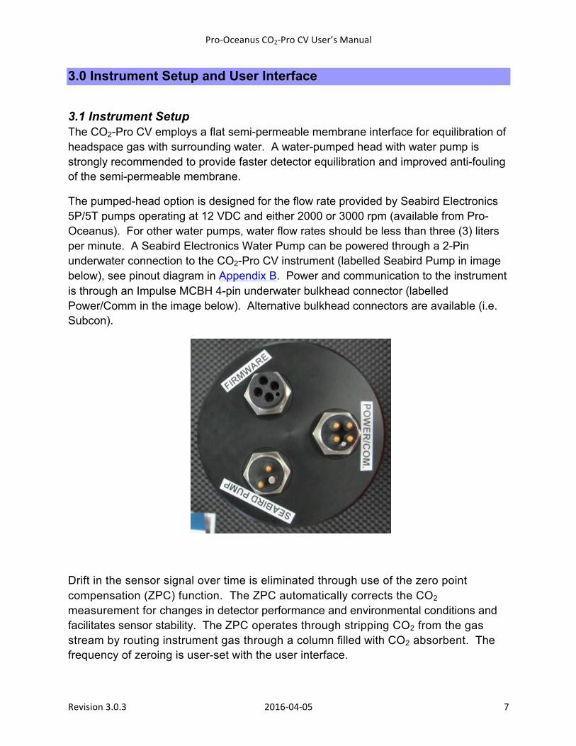
The pumped-head option is designed for the flow rate provided by Seabird Electronics 5P/5T pumps operating at 12 VDC and either 2000 or 3000 rpm (available from Pro-Oceanus). For other water pumps, water flow rates should be less than three (3) liters per minute. A Seabird Electronics Water Pump can be powered through a 2-Pin underwater connection to the CO2-Pro CV instrument (labelled Seabird Pump in image below), see pinout diagram in Appendix B. Power and communication to the instrument is through an Impulse MCBH 4-pin underwater bulkhead connector (labelled Power/Comm in the image below). Alternative bulkhead connectors are available (i.e. Subcon).
Drift in the sensor signal over time is eliminated through use of the zero point compensation (ZPC) function. The ZPC automatically corrects the CO2 measurement for changes in detector performance and environmental conditions and facilitates sensor stability. The ZPC operates through stripping CO2 from the gas stream by routing instrument gas through a column filled with CO2 absorbent. The frequency of zeroing is user-set with the user interface.
Pro-‐Oceanus CO2-‐Pro CV User’s Manual
Revision 3.0.3 2016-‐04-‐05 8
3.2 Sensor Communication and User Interface The CO2-Pro CV sensor can be equipped with an internal Oceanus Logger/ Controller module. The hardware provides the user with an easy to use system for modifying data logging parameters. Units without the logger/controller will still be controlled through the user interface described below, however, many of the features will not be available to the user.
*NOTE: The sensor does have the option for a separate operational mode that is outlined in Appendix C. This mode would be for customers who currently have non-logging CO2-Pro and CO2-Pro CV instruments and would like to have the same data format and functions as their current instrument.
Communication with the Oceanus Controller begins with a PC-based computer running Microsoft Windows. The computer must be equipped with a serial port, or a USB-serial cable with appropriate drivers installed. Any terminal program can be used to communicate with the Oceanus Logger. Tera Term is recommended by Pro-Oceanus and is freely available for download online. The setup of the communication port must be set as described below.
Serial Communications Parameter
Value
Baud rate 19200 Data bits 8 Parity none Stop bits 1
The logger completely controls the sensor to provide highly accurate data at the lowest possible power consumption. It handles all interface and timing functions and controls the water pump duty cycle, sensor power and wait times to provide accurate data that is stored in internal memory with a capacity of two gigabytes.
The logger has three operational modes with different options available for each. Continuous mode takes samples as fast as possible. Timed mode takes samples on a timed schedule. Command mode allows the user to trigger a single sampling sequence. Different options are provided for each mode to allow the user to fine tune the sampling process. Detailed settings for each mode are described in section 3.2.3
Pro-‐Oceanus CO2-‐Pro CV User’s Manual
Revision 3.0.3 2016-‐04-‐05 9
3.2.1 User Interface The logger is controlled and configured through the user interface that consists of a dedicated serial port and a menu driven command and control system. The serial port is normally shut down for low power consumption, but will power up automatically on the reception of any byte on the port. Once the system is powered up, an “escape” (0x1b hex) command is required to activate the user interface.
To begin communication with the Oceanus Logger/ Controller:
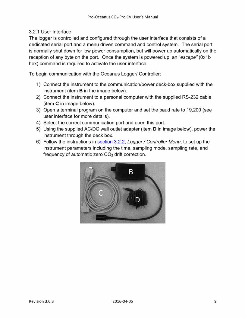
1) Connect the instrument to the communication/power deck-box supplied with the instrument (item B in the image below).
2) Connect the instrument to a personal computer with the supplied RS-232 cable (item C in image below).
3) Open a terminal program on the computer and set the baud rate to 19,200 (see user interface for more details).
4) Select the correct communication port and open this port. 5) Using the supplied AC/DC wall outlet adapter (item D in image below), power the
instrument through the deck box. 6) Follow the instructions in section 3.2.2, Logger / Controller Menu, to set up the
instrument parameters including the time, sampling mode, sampling rate, and frequency of automatic zero CO2 drift correction.
Pro-‐Oceanus CO2-‐Pro CV User’s Manual
Revision 3.0.3 2016-‐04-‐05 10
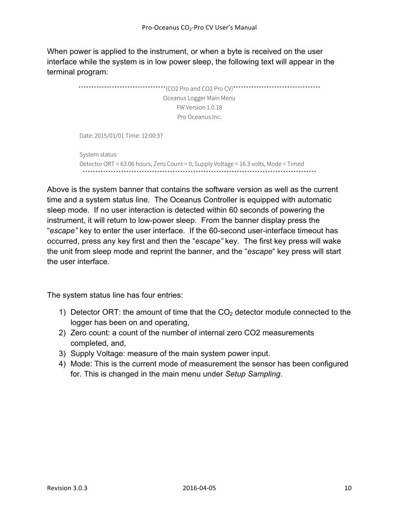
When power is applied to the instrument, or when a byte is received on the user interface while the system is in low power sleep, the following text will appear in the terminal program:
**********************************(CO2 Pro and CO2 Pro CV)********************************** Oceanus Logger Main Menu
FW Version 1.0.18 Pro Oceanus Inc.
Date: 2015/01/01 Time: 12:00:37 System status: Detector ORT = 63.06 hours, Zero Count = 0, Supply Voltage = 16.3 volts, Mode = Timed
*******************************************************************************************
Above is the system banner that contains the software version as well as the current time and a system status line. The Oceanus Controller is equipped with automatic sleep mode. If no user interaction is detected within 60 seconds of powering the instrument, it will return to low-power sleep. From the banner display press the “escape” key to enter the user interface. If the 60-second user-interface timeout has occurred, press any key first and then the “escape” key. The first key press will wake the unit from sleep mode and reprint the banner, and the “escape“ key press will start the user interface.
The system status line has four entries:
1) Detector ORT: the amount of time that the CO2 detector module connected to the logger has been on and operating,
2) Zero count: a count of the number of internal zero CO2 measurements completed, and,
3) Supply Voltage: measure of the main system power input. 4) Mode: This is the current mode of measurement the sensor has been configured
for. This is changed in the main menu under Setup Sampling.
Pro-‐Oceanus CO2-‐Pro CV User’s Manual
Revision 3.0.3 2016-‐04-‐05 11
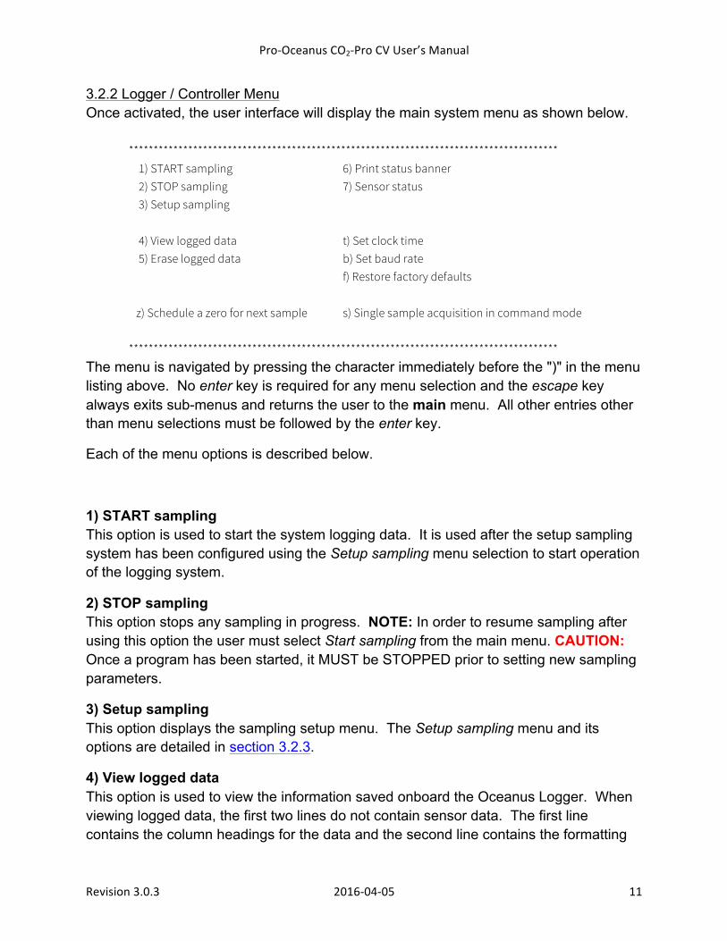
3.2.2 Logger / Controller Menu Once activated, the user interface will display the main system menu as shown below.
*************************************************************************************** 1) START sampling 6) Print status banner 2) STOP sampling 7) Sensor status 3) Setup sampling
4) View logged data t) Set clock time 5) Erase logged data b) Set baud rate
f) Restore factory defaults z) Schedule a zero for next sample s) Single sample acquisition in command mode
*************************************************************************************** The menu is navigated by pressing the character immediately before the ")" in the menu listing above. No enter key is required for any menu selection and the escape key always exits sub-menus and returns the user to the main menu. All other entries other than menu selections must be followed by the enter key.
Each of the menu options is described below.
1) START sampling This option is used to start the system logging data. It is used after the setup sampling system has been configured using the Setup sampling menu selection to start operation of the logging system.
2) STOP sampling This option stops any sampling in progress. NOTE: In order to resume sampling after using this option the user must select Start sampling from the main menu. CAUTION: Once a program has been started, it MUST be STOPPED prior to setting new sampling parameters.
3) Setup sampling This option displays the sampling setup menu. The Setup sampling menu and its options are detailed in section 3.2.3.
4) View logged data This option is used to view the information saved onboard the Oceanus Logger. When viewing logged data, the first two lines do not contain sensor data. The first line contains the column headings for the data and the second line contains the formatting
Pro-‐Oceanus CO2-‐Pro CV User’s Manual
Revision 3.0.3 2016-‐04-‐05 12
information used by the Pro-Oceanus Windows hosted user interface program (in development). Printing the data to a terminal program in this can be time consuming due to the limitation of baud rate. To reduce the time to download data in this manner, adjust the baud rate to the maximum allowable rate under the Set baud rate option. Ensure that the baud rate is then changed in the terminal program to allow communication. Pressing the escape key stops the printing and reprints the main menu returning control to the user. CAUTION: Viewing the data will stop all logging of data and the START sampling menu selection MUST be used to begin logging data again.
For faster data download, the micro-SD memory card may be removed from the internal logger electronics board (and read by a PC equipped with an SD card reader). The log file is named MainLog.txt and is in standard comma separated variable format that can be read by any spreadsheet program or text editor such as notepad. NOTE: For details on removing the micro-SD card, please contact Pro-Oceanus Systems.
5) Erase logged data This option is used to clear the memory of ALL internally saved data. To prevent the accidental deletion of data, a second confirmation is required. After a second confirmation, any saved data on the Oceanus Logger is permanently erased. Erasing the data will stop all logging of data and the START sampling menu selection must be used to begin logging data again.
6) Print status banner This selection displays the system banner.
7) Sensor status This option displays the factory settings menu. The factory settings are password protected and are not detailed in this manual.
t) Set clock time This option is used for changing the system clock that is used to sync all operations of the Oceanus Controller. After selecting this option, the user will be prompted to enter the year, month, day, as well as hour, minute and seconds. Time is entered in 24-hour format. NOTE: This must be completed before the start time of the first sample is set.
Pro-‐Oceanus CO2-‐Pro CV User’s Manual
Revision 3.0.3 2016-‐04-‐05 13
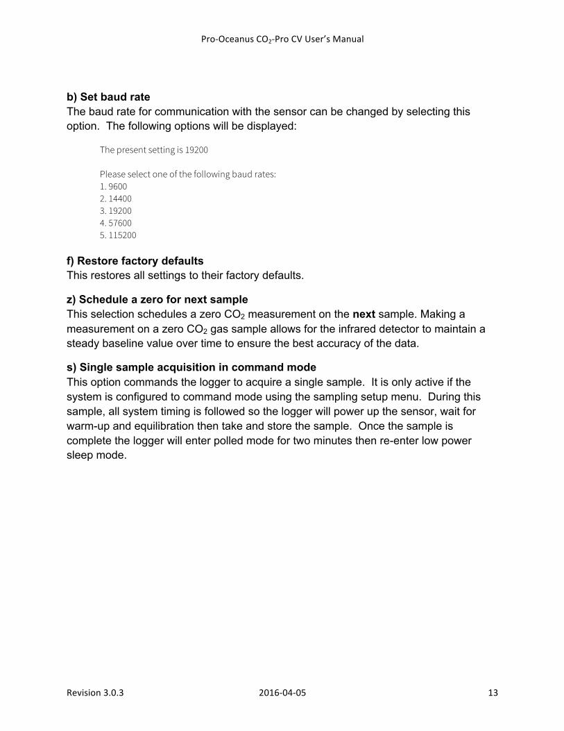
b) Set baud rate The baud rate for communication with the sensor can be changed by selecting this option. The following options will be displayed:
The present setting is 19200
Please select one of the following baud rates: 1. 9600 2. 14400 3. 19200 4. 57600 5. 115200
f) Restore factory defaults This restores all settings to their factory defaults.
z) Schedule a zero for next sample This selection schedules a zero CO2 measurement on the next sample. Making a measurement on a zero CO2 gas sample allows for the infrared detector to maintain a steady baseline value over time to ensure the best accuracy of the data.
s) Single sample acquisition in command mode This option commands the logger to acquire a single sample. It is only active if the system is configured to command mode using the sampling setup menu. During this sample, all system timing is followed so the logger will power up the sensor, wait for warm-up and equilibration then take and store the sample. Once the sample is complete the logger will enter polled mode for two minutes then re-enter low power sleep mode.
Pro-‐Oceanus CO2-‐Pro CV User’s Manual
Revision 3.0.3 2016-‐04-‐05 14
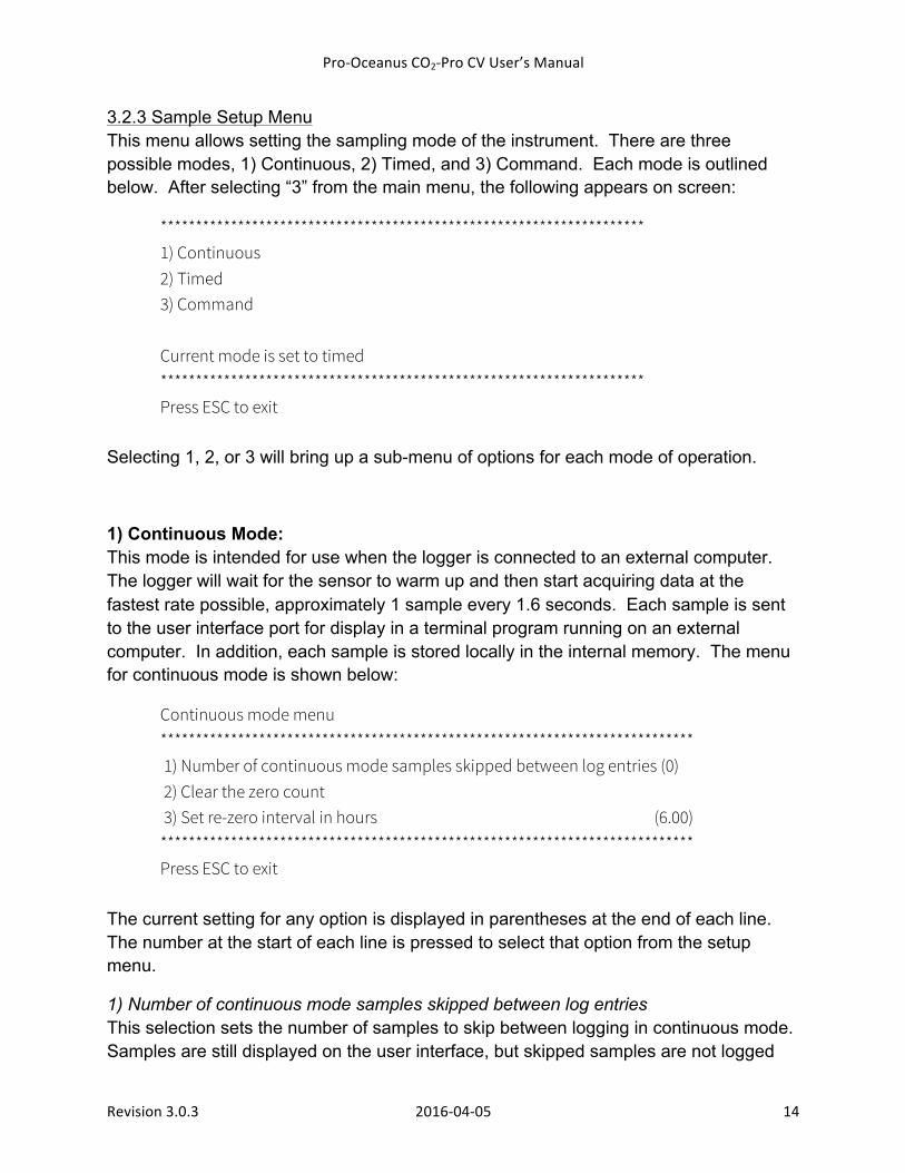
3.2.3 Sample Setup Menu This menu allows setting the sampling mode of the instrument. There are three possible modes, 1) Continuous, 2) Timed, and 3) Command. Each mode is outlined below. After selecting “3” from the main menu, the following appears on screen:
********************************************************************* 1) Continuous 2) Timed 3) Command
Current mode is set to timed ********************************************************************* Press ESC to exit
Selecting 1, 2, or 3 will bring up a sub-menu of options for each mode of operation.
1) Continuous Mode: This mode is intended for use when the logger is connected to an external computer. The logger will wait for the sensor to warm up and then start acquiring data at the fastest rate possible, approximately 1 sample every 1.6 seconds. Each sample is sent to the user interface port for display in a terminal program running on an external computer. In addition, each sample is stored locally in the internal memory. The menu for continuous mode is shown below:
Continuous mode menu **************************************************************************** 1) Number of continuous mode samples skipped between log entries (0) 2) Clear the zero count 3) Set re-zero interval in hours (6.00) **************************************************************************** Press ESC to exit
The current setting for any option is displayed in parentheses at the end of each line. The number at the start of each line is pressed to select that option from the setup menu.
1) Number of continuous mode samples skipped between log entries This selection sets the number of samples to skip between logging in continuous mode. Samples are still displayed on the user interface, but skipped samples are not logged
Pro-‐Oceanus CO2-‐Pro CV User’s Manual
Revision 3.0.3 2016-‐04-‐05 15
internally to save file space on the micro SD card. To save space in the memory, the logger can be configured to store every N'th reading, where N can range from zero to twenty.
2) Clear the zero count This selection clears the count of the number of zero point corrections completed. The zero count is used as a guide as to when the CO2 absorbent should be replaced. This option is used to clear the count when replacing the CO2 absorbent. The number of recommended zeroes between replacements of CO2 absorbent is dependent on a number of factors including time, CO2 level, and temperature. For most ocean applications, 300 zeroes is a reasonable number between CO2 replacements. NOTE: Pro-Oceanus does not guarantee the number of zeroes between CO2 absorbent replacement because of the range of factors in CO2 absorbent life. 3) Set re-zero interval in hours This sets the number of hours between zero point corrections (ZPC). Fractional hours are allowed with a minimum setting of 1 hour and a maximum of 24 hours between zeroing. The re-zero function is used to maintain calibration and accuracy of the detector. To ensure accurate measurements, zero CO2 readings should be taken periodically to adjust the sensor output for changes in environmental conditions and detector ageing effects. It is recommend to make at least two (2) zero CO2 measurements per day.
Pro-‐Oceanus CO2-‐Pro CV User’s Manual
Revision 3.0.3 2016-‐04-‐05 16
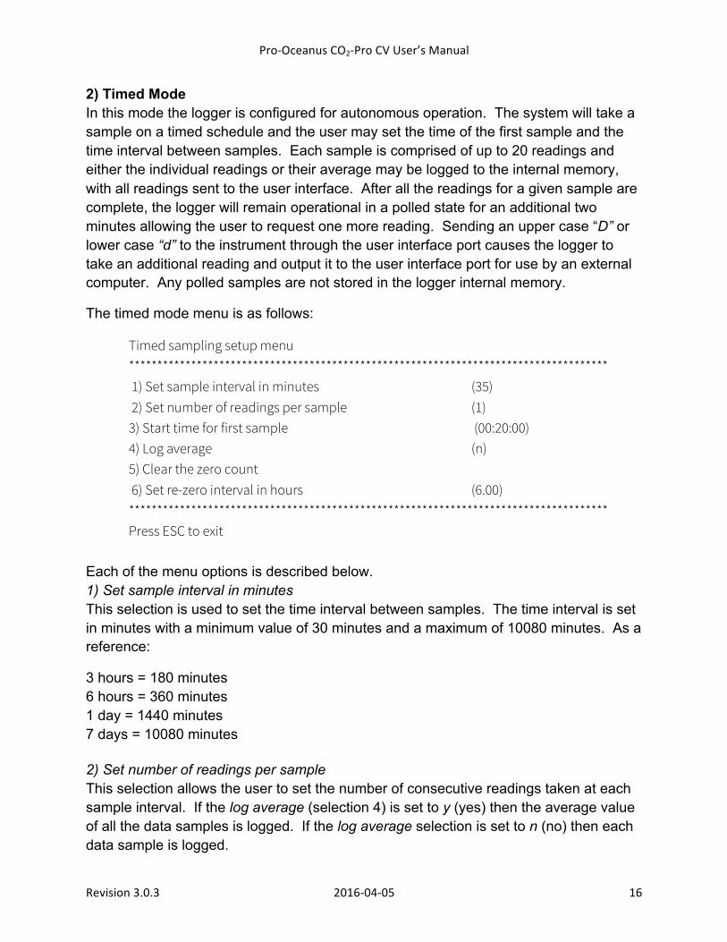
2) Timed Mode In this mode the logger is configured for autonomous operation. The system will take a sample on a timed schedule and the user may set the time of the first sample and the time interval between samples. Each sample is comprised of up to 20 readings and either the individual readings or their average may be logged to the internal memory, with all readings sent to the user interface. After all the readings for a given sample are complete, the logger will remain operational in a polled state for an additional two minutes allowing the user to request one more reading. Sending an upper case “D” or lower case “d” to the instrument through the user interface port causes the logger to take an additional reading and output it to the user interface port for use by an external computer. Any polled samples are not stored in the logger internal memory.
The timed mode menu is as follows:
Timed sampling setup menu ************************************************************************************* 1) Set sample interval in minutes (35) 2) Set number of readings per sample (1)
3) Start time for first sample (00:20:00) 4) Log average (n) 5) Clear the zero count
6) Set re-zero interval in hours (6.00) ************************************************************************************* Press ESC to exit
Each of the menu options is described below. 1) Set sample interval in minutes This selection is used to set the time interval between samples. The time interval is set in minutes with a minimum value of 30 minutes and a maximum of 10080 minutes. As a reference:
3 hours = 180 minutes 6 hours = 360 minutes 1 day = 1440 minutes 7 days = 10080 minutes 2) Set number of readings per sample This selection allows the user to set the number of consecutive readings taken at each sample interval. If the log average (selection 4) is set to y (yes) then the average value of all the data samples is logged. If the log average selection is set to n (no) then each data sample is logged.
Pro-‐Oceanus CO2-‐Pro CV User’s Manual
Revision 3.0.3 2016-‐04-‐05 17
3) Start time for first sample This sets the time of the first sample in timed mode. This allows for delays to deploy the sensor. Any time may be entered, up to 24 hours from the current time. The user will be prompted to enter the hour, the minute and the second of the start time. Setting a time before the present will result in a start time during the following day. The function basically acts as an alarm clock, waking the system and starting the first sample. NOTE: The start time must be set to at least 20 minutes beyond the current time in order to allow the sensor to turn on 20 minutes before the measurement. This time is required to provide sufficient time for the instrument to warm up and equilibrate.
4) Log average This selection allows averaging multiple readings for each sample in timed mode. If set to “y” (yes), the instrument will average N readings per sample. N is set using the number two selection from the sampling setup menu. If set to "n", (no) all readings will be logged for each sample.
5) Clear the zero count This selection clears the count of the number of zero point corrections completed. The zero count is used as a guide as to when the CO2 absorbent should be replaced. This option is used to clear the count when replacing the CO2 absorbent. The number of recommended zeroes between replacements of CO2 absorbent is dependent on a number of factors including time, CO2 level, and temperature. For most ocean applications, 300 zeroes is a reasonable number between CO2 replacements. NOTE: Pro-Oceanus does not guarantee the number of zeroes between CO2 absorbent replacement because of the range of factors in CO2 absorbent life.
6) Set re-zero interval in hours This sets the number of hours between zero point corrections (ZPC). Fractional hours are allowed with a minimum setting of 1 hour and a maximum of 24 hours between zeroing. The re-zero function is used to maintain calibration and accuracy of the detector. To ensure accurate measurements, zero CO2 readings should be taken periodically to adjust the sensor output for changes in environmental conditions and detector ageing effects. It is recommend to make at least two (2) zero CO2 measurements per day.
Pro-‐Oceanus CO2-‐Pro CV User’s Manual
Revision 3.0.3 2016-‐04-‐05 18
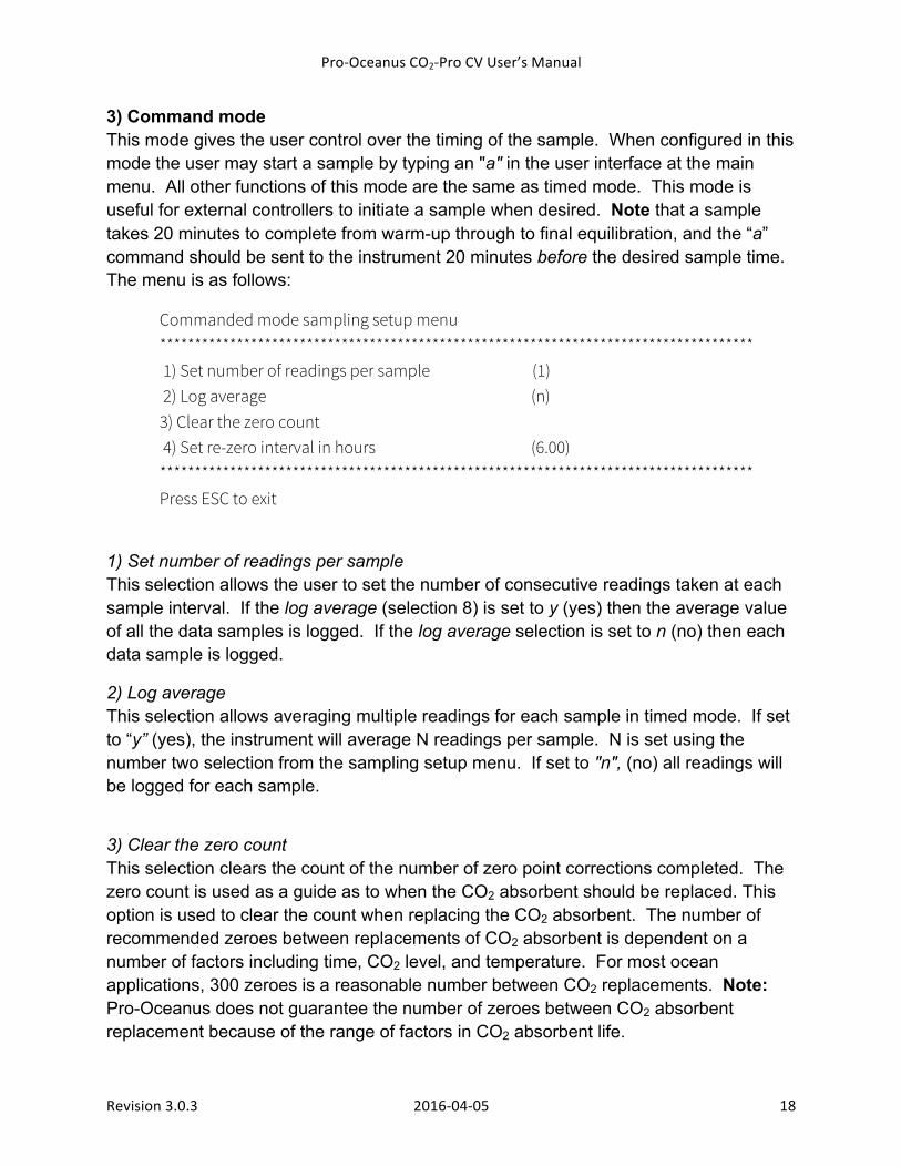
3) Command mode This mode gives the user control over the timing of the sample. When configured in this mode the user may start a sample by typing an "a" in the user interface at the main menu. All other functions of this mode are the same as timed mode. This mode is useful for external controllers to initiate a sample when desired. Note that a sample takes 20 minutes to complete from warm-up through to final equilibration, and the “a” command should be sent to the instrument 20 minutes before the desired sample time. The menu is as follows:
Commanded mode sampling setup menu ************************************************************************************* 1) Set number of readings per sample (1) 2) Log average (n)
3) Clear the zero count 4) Set re-zero interval in hours (6.00) ************************************************************************************* Press ESC to exit
1) Set number of readings per sample This selection allows the user to set the number of consecutive readings taken at each sample interval. If the log average (selection 8) is set to y (yes) then the average value of all the data samples is logged. If the log average selection is set to n (no) then each data sample is logged.
2) Log average This selection allows averaging multiple readings for each sample in timed mode. If set to “y” (yes), the instrument will average N readings per sample. N is set using the number two selection from the sampling setup menu. If set to "n", (no) all readings will be logged for each sample.
3) Clear the zero count This selection clears the count of the number of zero point corrections completed. The zero count is used as a guide as to when the CO2 absorbent should be replaced. This option is used to clear the count when replacing the CO2 absorbent. The number of recommended zeroes between replacements of CO2 absorbent is dependent on a number of factors including time, CO2 level, and temperature. For most ocean applications, 300 zeroes is a reasonable number between CO2 replacements. Note: Pro-Oceanus does not guarantee the number of zeroes between CO2 absorbent replacement because of the range of factors in CO2 absorbent life.
Pro-‐Oceanus CO2-‐Pro CV User’s Manual
Revision 3.0.3 2016-‐04-‐05 19
4) Set re-zero interval in hours This sets the number of hours between zero point corrections (ZPC). Fractional hours are allowed with a minimum setting of 1 hour and a maximum of 24 hours between zeroing. The re-zero function is used to maintain calibration and accuracy of the detector. To ensure accurate measurements, zero CO2 readings should be taken periodically to adjust the sensor output for changes in environmental conditions and detector ageing effects. It is recommend to make at least two (2) zero CO2 measurements per day.
3.2.4 Polling Data A feature of the sampled mode of operation is its polling capability. Sending an upper case “D” or lower case “d” after the instrument has finished logging a sample will return another line of data directly to the user terminal. This polling window remains open for 2 minutes after each logging interval before the unit returns to low power sleep mode. This data is not recorded on the micro SD card.
Pro-‐Oceanus CO2-‐Pro CV User’s Manual
Revision 3.0.3 2016-‐04-‐05 20
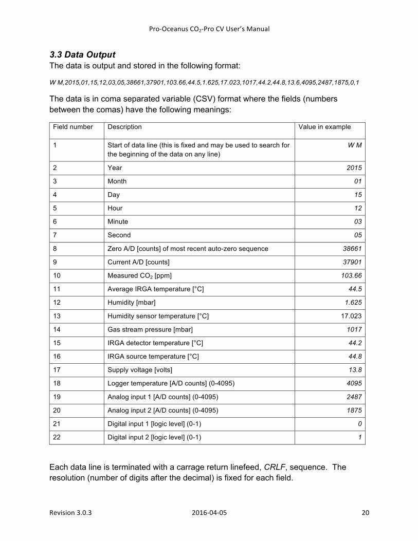
3.3 Data Output The data is output and stored in the following format:
W M,2015,01,15,12,03,05,38661,37901,103.66,44.5,1.625,17.023,1017,44.2,44.8,13.6,4095,2487,1875,0,1
The data is in coma separated variable (CSV) format where the fields (numbers between the comas) have the following meanings:
Field number Description Value in example
1 Start of data line (this is fixed and may be used to search for the beginning of the data on any line)
W M
2 Year 2015
3 Month 01
4 Day 15
5 Hour 12
6 Minute 03
7 Second 05
8 Zero A/D [counts] of most recent auto-zero sequence 38661
9 Current A/D [counts] 37901
10 Measured CO2 [ppm] 103.66
11 Average IRGA temperature [°C] 44.5
12 Humidity [mbar] 1.625
13 Humidity sensor temperature [°C] 17.023
14 Gas stream pressure [mbar] 1017
15 IRGA detector temperature [°C] 44.2
16 IRGA source temperature [°C] 44.8
17 Supply voltage [volts] 13.8
18 Logger temperature [A/D counts] (0-4095) 4095
19 Analog input 1 [A/D counts] (0-4095) 2487
20 Analog input 2 [A/D counts] (0-4095) 1875
21 Digital input 1 [logic level] (0-1) 0
22 Digital input 2 [logic level] (0-1) 1
Each data line is terminated with a carrage return linefeed, CRLF, sequence. The resolution (number of digits after the decimal) is fixed for each field.
Pro-‐Oceanus CO2-‐Pro CV User’s Manual
Revision 3.0.3 2016-‐04-‐05 21
4.0 CO2 Measurement
4.1 Equilibration dynamics and instrument response time The equilibrium of dissolved gas sensors with surrounding water requires diffusion of molecules from a liquid across a semi-permeable membrane to a gaseous headspace. Once in the gas phase, detectors are used to measure a concentration in gaseous form. Several factors affect the time it takes to equilibrate a gas headspace with a surrounding water parcel through a semi-permeable membrane. The main factors are described below.
There is a finite time that is required for the shift between the dissolved and gas phases of a substance due to the kinetics of solubility. The rate is dependent on temperature and salinity, and to a much lesser degree, pressure.
The membrane effect can be described using the Laws of Diffusion, whereby the diffusion coefficient of the semi-permeable membrane is a function of the gas solubility coefficient in the membrane, and the permeability of that gas through the membrane. The thickness of the membrane also plays a crucial role in the time for equilibration. Temperature and salinity can dramatically affect the diffusion through a membrane.
The equilibration rate of diffusion processes is often measured in terms of a time constant, t63. This represents the time it takes reach 63% of equilibrium. The flux of gases across a membrane is a function of the gradient of difference between the concentrations on either side of the membrane. For example, the flux of a gas across a membrane will be rapid when the difference in concentration in surrounding water and the gas headspace is large. As a gas moves across the membrane either into or out of the gas headspace, the concentration gradient decreases, and as a result, the rate of gas flux across the membranes slows.
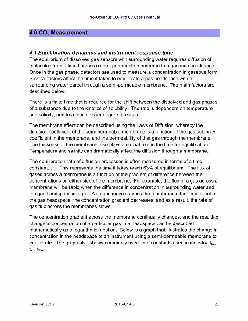
The concentration gradient across the membrane continually changes, and the resulting change in concentration of a particular gas in a headspace can be described mathematically as a logarithmic function. Below is a graph that illustrates the change in concentration in the headspace of an instrument using a semi-permeable membrane to equilibrate. The graph also shows commonly used time constants used in industry, t63, t90, t95.
Pro-‐Oceanus CO2-‐Pro CV User’s Manual
Revision 3.0.3 2016-‐04-‐05 22
t63 is taken as one fifth of the total time to equilibrate, t90 is approximately half the time to equilibrate, and t95 is roughly 60% of the time to equilibrate. t99 is taken as teq.
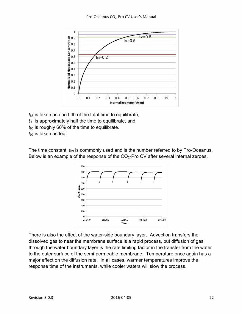
The time constant, t63 is commonly used and is the number referred to by Pro-Oceanus. Below is an example of the response of the CO2-Pro CV after several internal zeroes.
There is also the effect of the water-side boundary layer. Advection transfers the dissolved gas to near the membrane surface is a rapid process, but diffusion of gas through the water boundary layer is the rate limiting factor in the transfer from the water to the outer surface of the semi-permeable membrane. Temperature once again has a major effect on the diffusion rate. In all cases, warmer temperatures improve the response time of the instruments, while cooler waters will slow the process.
Pro-‐Oceanus CO2-‐Pro CV User’s Manual
Revision 3.0.3 2016-‐04-‐05 23
The thickness of the boundary layer can vary (and as a result, so too does the time to diffuse through the boundary layer) and the thickness is determined by the hydrodynamics next to the membrane surface. Stagnant water will produce the thickest boundary layer, resulting in the slowest response time. Maximizing the water shear across the membrane surface will reduce the boundary layer thickness to a minimum and is recommended using a Pro-Oceanus pumped head assembly. The effect of high shear also reduces the potential for biofouling of the instrument.
4.2 Infrared detection method The CO2-Pro CV instrument employs a non-dispersive infrared detector (NDIR) to facilitate the measurement of the wet mole fraction of CO2 in the gas phase that is in equilibrium with the surrounding water. Measurement of CO2 using IR-based detectors is a standard method for accurate determination of CO2 at both low and high concentrations.
IR detection measures a gaseous mole fraction of CO2 within the measurement cell and the output must be corrected for any pressure variations within the cell. A pressure sensor within the detector cell outputs the pressure in millibars (see Data Output). This pressure is used to internally correct the CO2 measurement and this value is output by the instrument.
Pressure Dependence of Signal: The dependence of the gas pressure within an NDIR cell is an important, yet often understated issue in measuring gas concentration accurately. The underlying physical principles of NDIR sensor gas detection provide a measure of the number of molecules of a specific gas. In order to accurately calculate the concentration, the total gas pressure must be known in order to determine the ratio of molecules being measured versus the total number of molecules.
The CO2-Pro CV detector is fully pressure compensated so that changes in gas pressure are corrected for without the need for post-processing. The pressure of gas inside the detector cell can also be used to estimate the partial pressure of CO2, pCO2.
Temperature Dependence: Changes in temperature within the detector cell will affect the accuracy of the measurement if not appropriately corrected. As gas molecules are heated, their
Pro-‐Oceanus CO2-‐Pro CV User’s Manual
Revision 3.0.3 2016-‐04-‐05 24
velocities increase, leading to the apparent increase in the number of gas molecules in a given volume by a NDIR detector.
The Pro-Oceanus CO2-Pro CV has an internally stabilized gas detector cell temperature that is held at a temperature well above the surrounding water temperature to prevent condensation within the sensing cell.
4.3 Partial pressure of CO2, pCO2 CO2 (g) is commonly measured in units of ppm (parts per million). This is the molar ratio of x number of CO2 molecules per million molecules of total gas. The ppm of CO2 in air does not change with pressure. Ppm CO2 is also referred to as the mixing ratio, xCO2.
In natural waters, CO2 (g) is often reported as a partial pressure, pCO2, with units of microatmospheres (µatm). Unlike xCO2, pCO2 is dependent on the total gas pressure. The two terms are related through pressure by:
pCO2 = xCO2 X P (4.1),
where P is pressure measured in microatmospheres and xCO2 is in ppm.
A third unit of measure for CO2 is the fugacity, fCO2. The fugacity corrects for non-ideal gas behavior of gases and can be estimated from approximate expressions along with temperature and pCO2. In most cases fCO2 is within a few µatm of pCO2.
The CO2-Pro CV measures the “wet” (i.e. partial pressure of water vapour included) xCO2 of a gas stream that has equilibrated with surrounding water. In addition, the sensor measures the total pressure, P, of the gas stream, in millibars (mbar). The measured ppm output from the sensor is corrected for pressure variation, as is needed for NDIR measurement. By converting the measured gas pressure to units of atmospheres:
P (mbar) / 1013.25 /1000000 = P (µatm) (4.2),
pCO2 (µatm) can then be calculated using Eq. 4.1.
Typically, headspace equilibrators remove water vapor prior to measurement of CO2, and must be corrected for this. The CO2-Pro CV sensor measures the “wet” CO2 concentration and do not need to be corrected for water vapor.
Pro-‐Oceanus CO2-‐Pro CV User’s Manual
Revision 3.0.3 2016-‐04-‐05 25
4.4 CO2 solubility and dissolved phase concentration The measurement of CO2 in water is facilitated by the CO2-Pro CV through equilibration of a gas headspace with surrounding water. This results in a measurement that is in the “gas” phase as a partial pressure of the total gas pressure equilibrated with the water. The same equilibration dynamics occur at the surface of a body of water in contact with the atmosphere, such that the concentration of CO2 in the water is in equilibrium with the partial pressure of CO2 in the atmosphere.
𝐶𝑂! 𝑔 ↔ 𝐶𝑂!(𝑎𝑞) (4.3).
The equilibrated ratio of partial pressure to dissolved concentration is governed by:
𝑝𝐶𝑂! = 𝐾![𝐶𝑂! 𝑎𝑞 ] (4.4),
where pCO2 is the partial pressure of CO2 in the gas phase, Ko is a solubility coefficient, and CO2 (aq) is the concentration of CO2 dissolved in the water.
The units of pCO2 used in the equations that follows are µatm.
The solubility of CO2 in water is a function of both the temperature and the salinity of the water, from Weiss (1974):
ln 𝐾! = −60.2409+ 93.4517 !""!
+ 23.3585 ln !!""
+ (4.5),
𝑆(0.023517− 0.023656 !!""
+ 0.0047036 !!""
!)
Where the solubility coefficient, Ko has the units of mol kg-1 atm-1, temperature is Kelvin, and salinity is in parts per thousand (approximately equal to PSU).
For non-saline waters, the second term of the equation becomes zero, leading to:
ln 𝐾! = −60.2409+ 93.4517 !""!
+ 23.3585 ln !!""
(4.6).
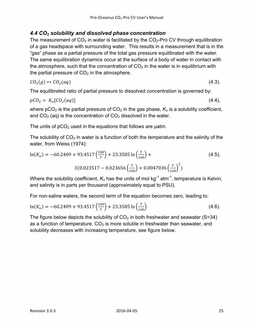
The figure below depicts the solubility of CO2 in both freshwater and seawater (S=34) as a function of temperature. CO2 is more soluble in freshwater than seawater, and solubility decreases with increasing temperature, see figure below.
Pro-‐Oceanus CO2-‐Pro CV User’s Manual
Revision 3.0.3 2016-‐04-‐05 26
An excel spreadsheet for conversion calculations can be obtained by contacting Pro-Oceanus Systems.
Reference: Weiss, RF. 1974. Carbon dioxide in water and seawater: the solubility of a non-ideal gas. Marine Chemistry. 2:203-215. 10.1016/0304-4203(74)90015-2.
Pro-‐Oceanus CO2-‐Pro CV User’s Manual
Revision 3.0.3 2016-‐04-‐05 27
5.0 Instrument Deployment 5.1 Pre-deployment set-up Prior to deployment of the CO2-Pro CV, cleaning the instrument’s semi-permeable membrane is highly recommended to ensure accurate CO2 measurements and fastest equilibration times. The membrane is the most important part of the instrument and great care must be taken to not damage the instrument during cleaning. Section 6.3 describes the recommended cleaning process. If the membrane appears to be damaged, the user can replace it, as described in Section 6.4.
The current instrument zero count should be checked to ensure that the CO2 absorbent is sufficient to provide accurate zero measurements for the duration of the scheduled deployment period. The replacement of the CO2 absorbent is described in Section 6.2. When replacing the absorbent, it is also recommended to replace the internal clock battery (Section 6.3). This battery ensures the instrument maintains accurate time even when power is removed from the instrument.
Immediately prior to deployment, the user must program the instrument clock time and sampling routine, and first sample start time, as described in the previous section. Note that the sample start time must be set to at least 20 minutes after setting up the sampling parameters, to allow for the instrument to thermally stabilize and equilibrate before the scheduled measurement.
5.2 Recommended Deployment Practices After ensuring the instrument is configured correctly for sampling mode and frequency, deployment of the instrument is simple. It is recommended that the sensor be mounted in a horizontal position if possible, however, a vertical mount with the instrument membrane head pointed downwards may be more practical on a mooring and this is an acceptable orientation. If mounting the sensor head pointed downwards, ensure that gas does not become trapped along the outside of the membrane. A simple solution to this is to briefly tilt the sensor to a horizontal position once in placed into the water prior to deployment.
During deployment, the instrument membrane may not be fully compressed against its support and this will lead to elevated total dissolved gas pressure inside the gas stream where CO2 is measured. While the detector compensates for changes in gas pressure, readings may not be within the specified accuracy while this excess pressure is released via diffusion through the membrane.
Pro-‐Oceanus CO2-‐Pro CV User’s Manual
Revision 3.0.3 2016-‐04-‐05 28
Biofouling is always a concern for instrumentation deployed for long periods of time. Any additional biofouling prevention that can be used to aide in providing an accurate CO2 measurement is encouraged. The instrument will not be affected by most traditional biofouling methods, but if you are unsure about the method and its affect on the CO2-Pro CV and its measurement, contact Pro-Oceanus.
Caution: In areas when total dissolved gas pressure (TDGP) is substantially above atmospheric pressure, caution is required when removing the instrument from water. As water pressure holds the membrane against a rigid support when submerged, any gas pressure buildup on the gas side of the membrane can result in bulging of the membrane when removed from immersion. In the case of high TDGP, it is recommended to slowly bring the instrument to the surface while monitoring gas pressure. The excess gas pressure will slowly dissipate as the instrument approaches waters in equilibrium with the atmosphere.
5.3 Integration Options The CO2-Pro CV can easily be integrated into a number of platforms. It provides real-time data that does not require any post-processing of data, allowing for direct input into a system with minimal effort.
If you have a specific requirement for integration and require assistance, Pro-Oceanus staff can assist in this process.
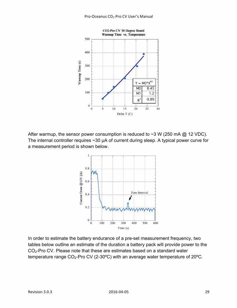
5.4 Power Budgets The CO2-Pro CV can be operated using direct cable power input or through an external battery pack. The power required by the instrument varies based on the difference in between the surrounding water temperature and the detector temperature. The detector temperature is factory-set prior to instrument calibration and this temperature is chosen to be, at a minimum, 10-15ºC above the maximum water temperature in which the instrument will be making measurements. This temperature difference is required to prevent condensation inside the detector cell.
The result of having a thermally stable detector is that accuracy is improved. The internal heater element requires additional power during the “warm-up” of the instrument. The average power consumption during warmup for the CO2-Pro CV is 9 W (750 mA @ 12 VDC). The duration of warmup is dependent on the temperature differential and the graph below shows an approximate warmup time based on the difference in the detector temperature and the surrounding water.
Pro-‐Oceanus CO2-‐Pro CV User’s Manual
Revision 3.0.3 2016-‐04-‐05 29
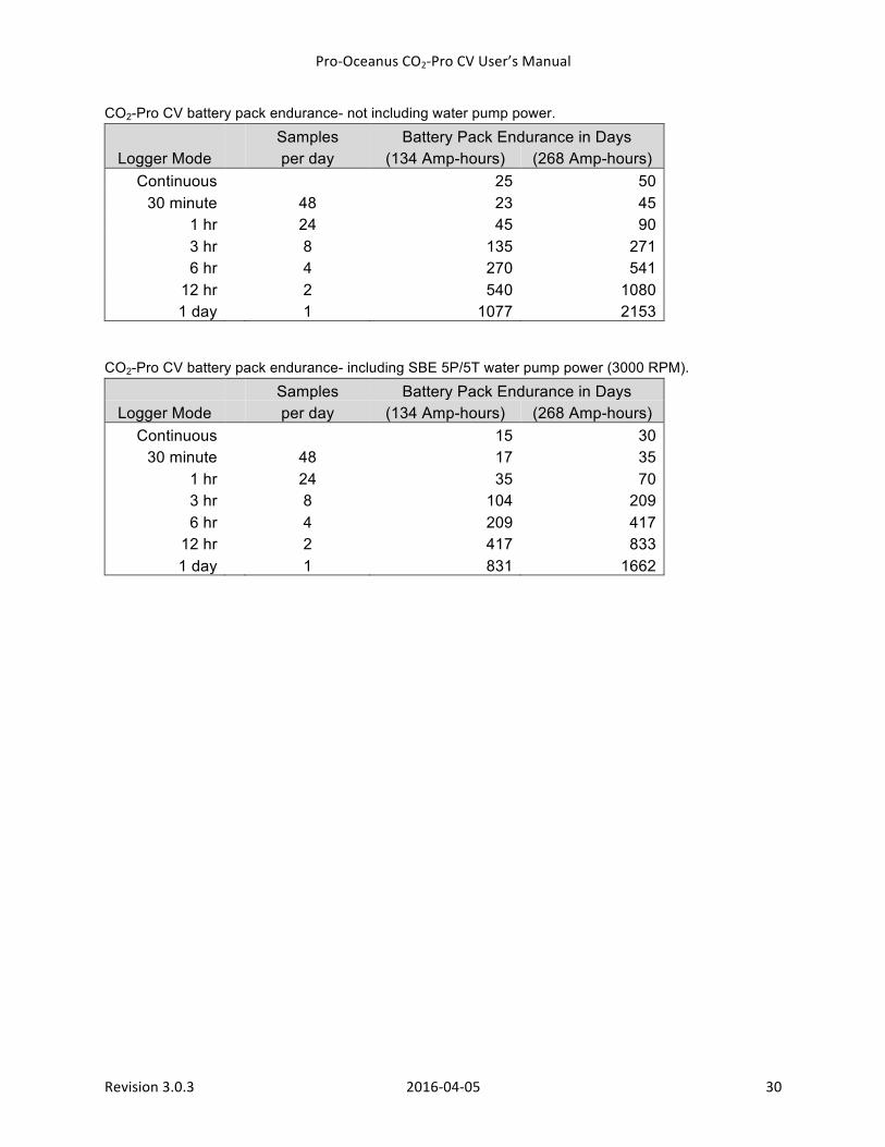
After warmup, the sensor power consumption is reduced to ~3 W (250 mA @ 12 VDC). The internal controller requires ~30 µA of current during sleep. A typical power curve for a measurement period is shown below.
In order to estimate the battery endurance of a pre-set measurement frequency, two tables below outline an estimate of the duration a battery pack will provide power to the CO2-Pro CV. Please note that these are estimates based on a standard water temperature range CO2-Pro CV (2-30ºC) with an average water temperature of 20ºC.
Pro-‐Oceanus CO2-‐Pro CV User’s Manual
Revision 3.0.3 2016-‐04-‐05 30
CO2-Pro CV battery pack endurance- not including water pump power.
Samples Battery Pack Endurance in Days Logger Mode per day (134 Amp-hours) (268 Amp-hours)
Continuous
25 50 30 minute
48 23 45
1 hr
24 45 90 3 hr
8 135 271
6 hr
4 270 541 12 hr
2 540 1080
1 day 1 1077 2153
CO2-Pro CV battery pack endurance- including SBE 5P/5T water pump power (3000 RPM).
Samples Battery Pack Endurance in Days Logger Mode per day (134 Amp-hours) (268 Amp-hours)
Continuous
15 30 30 minute
48 17 35
1 hr
24 35 70 3 hr
8 104 209
6 hr
4 209 417 12 hr
2 417 833
1 day 1 831 1662
Pro-‐Oceanus CO2-‐Pro CV User’s Manual
Revision 3.0.3 2016-‐04-‐05 31
6.0 Care and Maintenance 6.1 Instrument Housing and Bulkhead Connectors The standard CO2-Pro CV instrument is made of acetal plastic and uses 316 stainless steel screws and electrical connectors. The optional titanium housing uses titanium screws and electrical bulkhead connectors.
Upon recovery, rinse the external surface of the housing with clean, fresh water. Mild detergents may be used to help remove biofilms. A soft cloth can be used on the housing to remove larger and more difficult to remove biological material. See “Cleaning the Interface” for instructions on proper maintenance of the interface.
Unplug all cables and dummy plugs from the rear of the housing and inspect the connectors for corrosion. Apply a light coat of non-conductive grease to each of the connector pins. Re-connect electrical cables and plugs and ensure the lock-down sleeves are secured. Do not over-tighten the locking sleeves, hand tighten only.
6.2 Replacing the CO2 Absorbent Under normal conditions of use, the absorbent should not need replacing more than once per year, but must be replaced if the CO2 zero drops significantly below previous levels obtained under the same environmental conditions. It is recommended that the CO2 absorbent be replaced if the instrument is to be deployed for an extended period. Note: Ascarite II is the preferred absorbent and is supplied in 8-20 mesh granule size and it must be used with Drierite to ensure best lifespan. Sodalime can also be used and should not be used with Drierite. MSDS sheets for Ascarite II, Sodalime, and Drierite are in Appendix D.
To replace the CO2 absorbent, follow the steps below.
1) Place the instrument on a clean flat surface. The use of two small pieces of soft foam will aid in preventing the instrument from rolling.
2) If the instrument pumped head option is included, ensure it is securing in place to protect the membrane from damage.
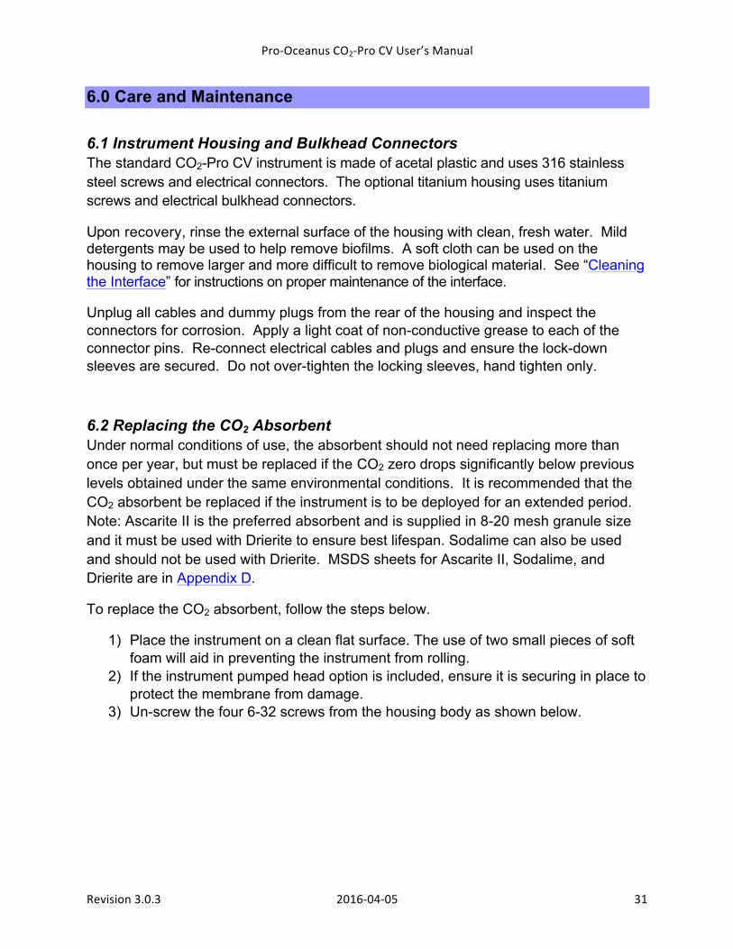
3) Un-screw the four 6-32 screws from the housing body as shown below.
Pro-‐Oceanus CO2-‐Pro CV User’s Manual
Revision 3.0.3 2016-‐04-‐05 32
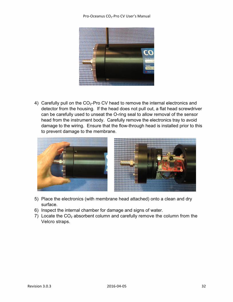
4) Carefully pull on the CO2-Pro CV head to remove the internal electronics and detector from the housing. If the head does not pull out, a flat head screwdriver can be carefully used to unseat the O-ring seal to allow removal of the sensor head from the instrument body. Carefully remove the electronics tray to avoid damage to the wiring. Ensure that the flow-through head is installed prior to this to prevent damage to the membrane.
5) Place the electronics (with membrane head attached) onto a clean and dry surface.
6) Inspect the internal chamber for damage and signs of water. 7) Locate the CO2 absorbent column and carefully remove the column from the
Velcro straps.
Pro-‐Oceanus CO2-‐Pro CV User’s Manual
Revision 3.0.3 2016-‐04-‐05 33
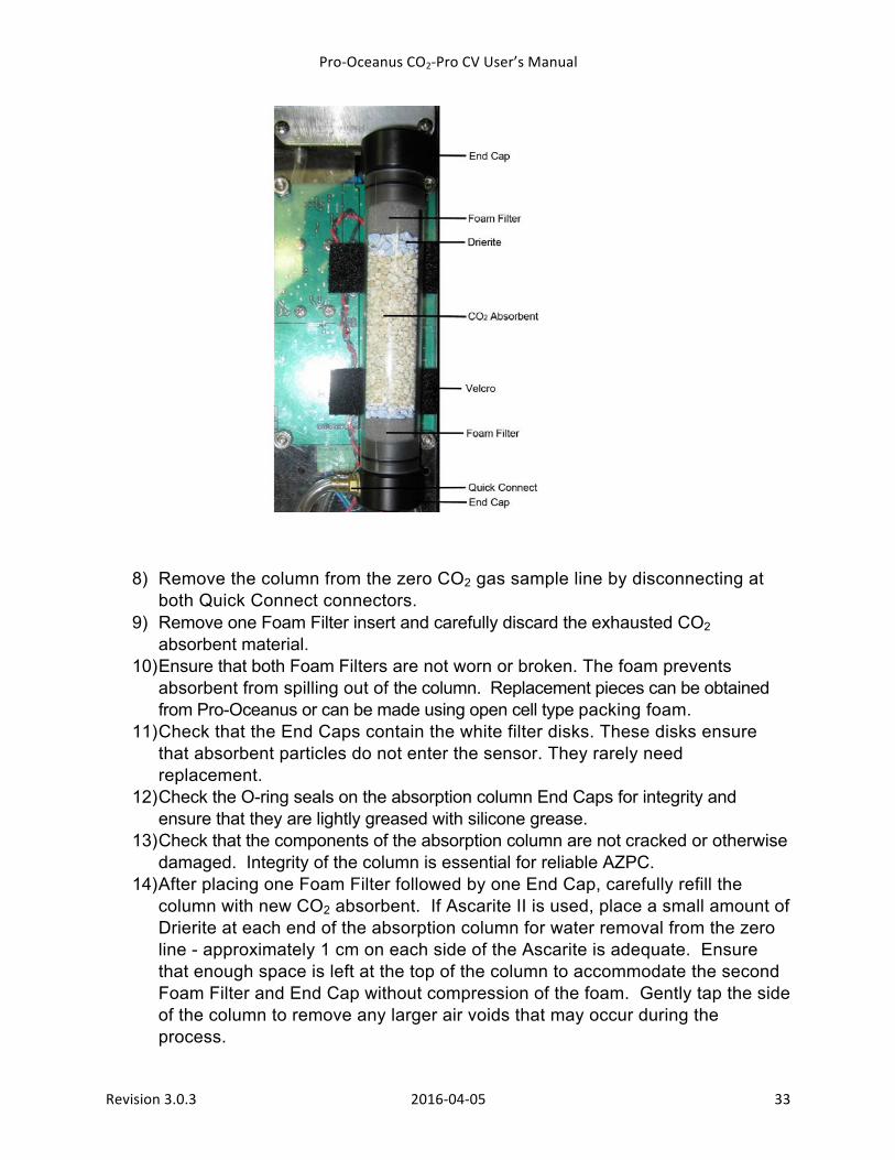
8) Remove the column from the zero CO2 gas sample line by disconnecting at both Quick Connect connectors.
9) Remove one Foam Filter insert and carefully discard the exhausted CO2 absorbent material.
10) Ensure that both Foam Filters are not worn or broken. The foam prevents absorbent from spilling out of the column. Replacement pieces can be obtained from Pro-Oceanus or can be made using open cell type packing foam.
11) Check that the End Caps contain the white filter disks. These disks ensure that absorbent particles do not enter the sensor. They rarely need replacement.
12) Check the O-ring seals on the absorption column End Caps for integrity and ensure that they are lightly greased with silicone grease.
13) Check that the components of the absorption column are not cracked or otherwise damaged. Integrity of the column is essential for reliable AZPC.
14) After placing one Foam Filter followed by one End Cap, carefully refill the column with new CO2 absorbent. If Ascarite II is used, place a small amount of Drierite at each end of the absorption column for water removal from the zero line - approximately 1 cm on each side of the Ascarite is adequate. Ensure that enough space is left at the top of the column to accommodate the second Foam Filter and End Cap without compression of the foam. Gently tap the side of the column to remove any larger air voids that may occur during the process.
Pro-‐Oceanus CO2-‐Pro CV User’s Manual
Revision 3.0.3 2016-‐04-‐05 34
15) Re-insert the second Foam Filter and End Cap. 16) Re-connect the column to the zeroing sample line using the Quick Connect
connectors. 17) Secure the column in place using the Velcro straps. 18) Carefully remove the housing endcap O-ring (see image below) using a plastic
object. Do not scratch the O-ring groove or O-ring, as this could compromise the pressure rating of the instrument.
19) Lightly grease a new O-ring (Size 233- 2 7/8” x 1/8”, BUNA 70 Durometer) and install into O-ring groove.
20) Carefully insert the instrument electronics tray back into the housing taking care to ensure all the internal components are not pinched against the instrument housing.
21) Insert the four screws that hold the sensor head in place.
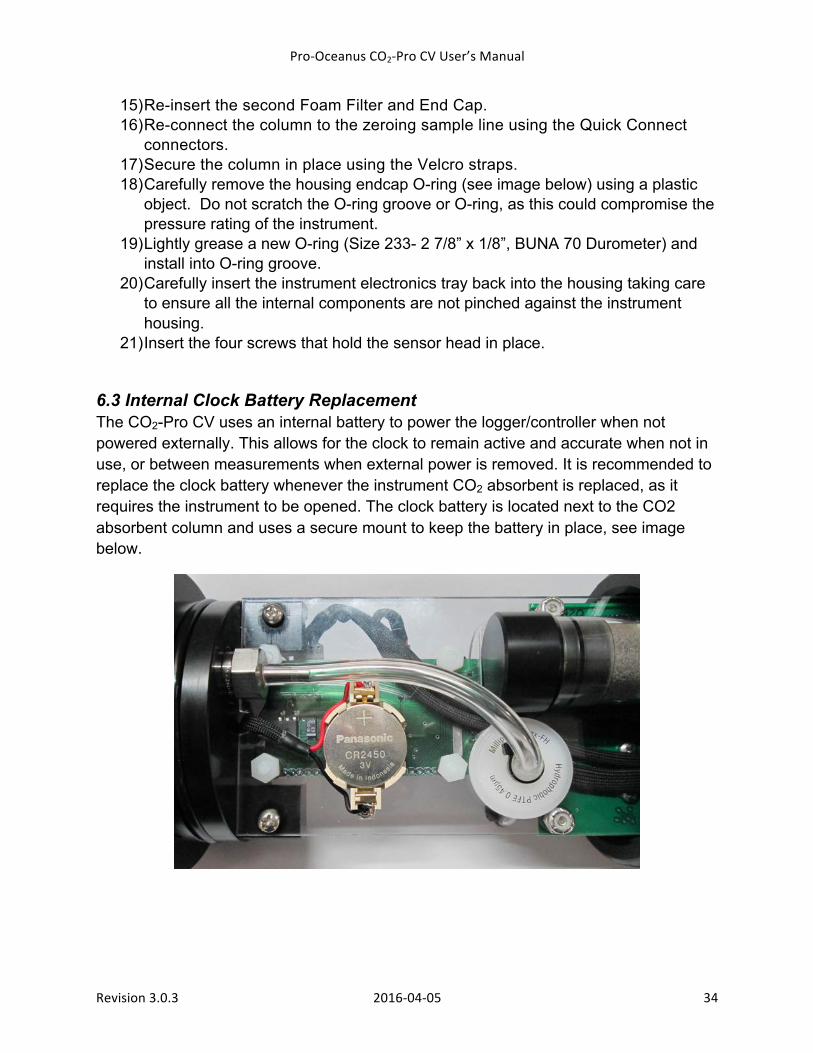
6.3 Internal Clock Battery Replacement The CO2-Pro CV uses an internal battery to power the logger/controller when not powered externally. This allows for the clock to remain active and accurate when not in use, or between measurements when external power is removed. It is recommended to replace the clock battery whenever the instrument CO2 absorbent is replaced, as it requires the instrument to be opened. The clock battery is located next to the CO2 absorbent column and uses a secure mount to keep the battery in place, see image below.

Pro-‐Oceanus CO2-‐Pro CV User’s Manual
Revision 3.0.3 2016-‐04-‐05 35
The battery model is a 3V Panasonic CR2450, and can continually power the instrument’s clock and maintain the sensor in sleep mode for more than 3 years if needed (at 20 degrees Celsius with new battery).
6.4 Cleaning and Replacing the Interface The gas transfer interface is a semi-permeable membrane. The instrument is designed to allow removal of the membrane for both cleaning and replacement if required. The flow-through water head is engineered to minimize biofouling, however, under most conditions biofilms will eventually form on the surface. This leads to two effects, 1) a slowdown of the equilibration rate due to decreased permeability of the membrane, and in rare instances, 2) the production of CO2 by the organisms of the biofilms can result in erroneous data. Regular cleaning can minimize this effect.
In the laboratory, immerse the instrument in a solution of dilute cleaning agent, oil-free detergent is recommended. Use a water pump attached to the water-pumped head to flow the soapy water solution across the membrane, a flow rate of 1-3 liters per minute for 30 minutes is recommended. If the instrument has a clear flow-through head, inspect the membrane to see when it appears to be clean and free of biofilm and debris will allow the user to determine how long is required. In other cases, the CO2-Pro CV pumped head may need to be removed to dislodge debris or to inspect the membrane. If this is required, use a 3/32” hex key to remove the six socket head screws (4-40 thread x ½” length) from the face of the flow-through head as shown in the images below.
Pro-‐Oceanus CO2-‐Pro CV User’s Manual
Revision 3.0.3 2016-‐04-‐05 36
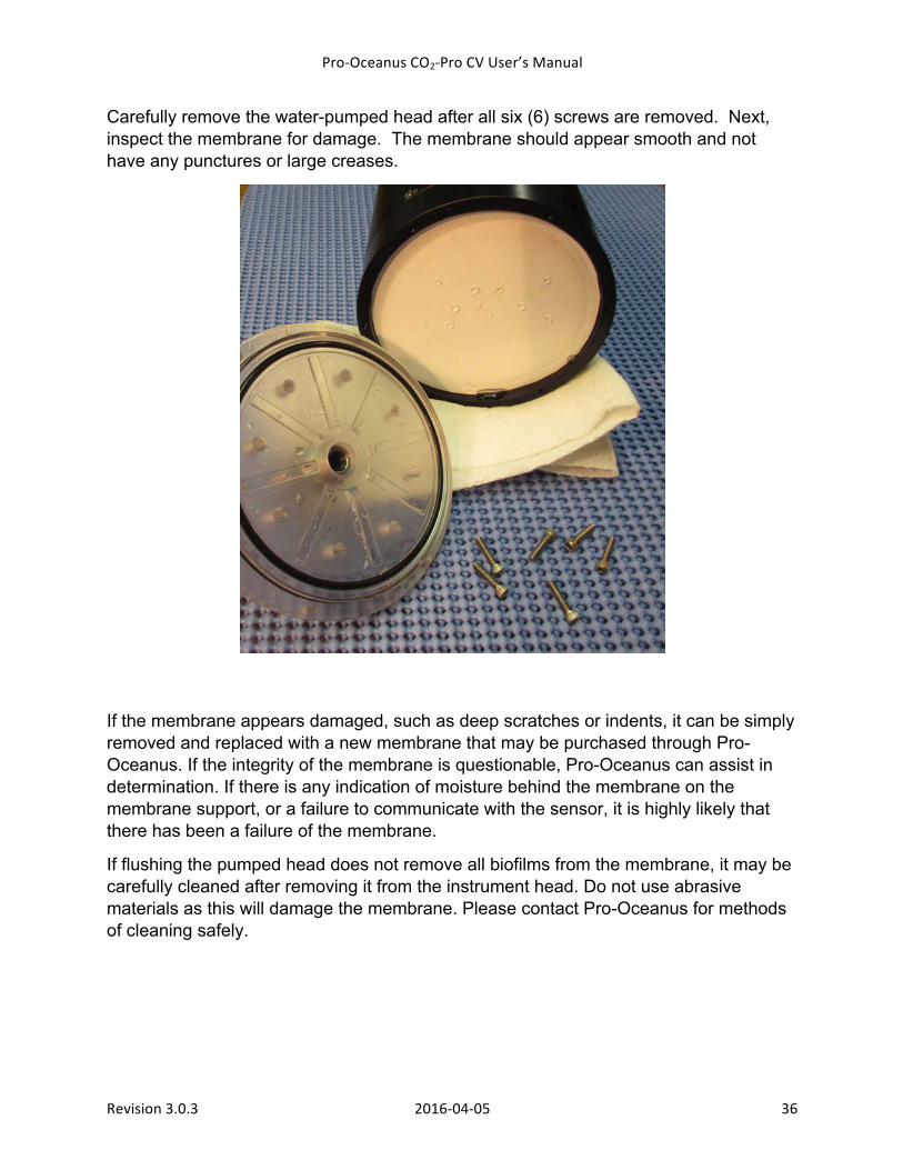
Carefully remove the water-pumped head after all six (6) screws are removed. Next, inspect the membrane for damage. The membrane should appear smooth and not have any punctures or large creases.
If the membrane appears damaged, such as deep scratches or indents, it can be simply removed and replaced with a new membrane that may be purchased through Pro-Oceanus. If the integrity of the membrane is questionable, Pro-Oceanus can assist in determination. If there is any indication of moisture behind the membrane on the membrane support, or a failure to communicate with the sensor, it is highly likely that there has been a failure of the membrane.
If flushing the pumped head does not remove all biofilms from the membrane, it may be carefully cleaned after removing it from the instrument head. Do not use abrasive materials as this will damage the membrane. Please contact Pro-Oceanus for methods of cleaning safely.
Pro-‐Oceanus CO2-‐Pro CV User’s Manual
Revision 3.0.3 2016-‐04-‐05 37
6.5 Detector Re-Calibration Calibration of the CO2-Pro CV must be completed by Pro-Oceanus staff. The calibration procedure requires 5-9 NOAA ESRL GMD traceable gases and a proprietary three-segment polynomial curve fit. Multiple calibrations are made in sequence to ensure the best possible accuracy.
It is recommended that each CO2-Pro CV to be returned to Pro-Oceanus once every 12-18 months for re-calibration and functional testing. Normal sensor drift over one year is typically less than 5 ppm.
To return an instrument for re-calibration, please contact Pro-Oceanus for an RMA number prior to shipping it freight pre-paid to Pro-Oceanus:
Pro-Oceanus Systems 80 Pleasant Street
Bridgewater, NS, CANADA B4V 1N1
Carefully package in the instrument’s original protective case, and clearly mark as “fragile goods” and “return for repair” on the outside of the case.
Pro-‐Oceanus CO2-‐Pro CV User’s Manual
Revision 3.0.3 2016-‐04-‐05 38
7.0 Troubleshooting
1) No power: check the power supply (should be 12-18 VDC); if no power is reaching the instrument, check the fuse in the deckbox and replace if necessary.
2) Erratic CO2 measurement: re-zero; if still a problem, open instrument head and ensure that all tubing is in place and connected and replace the CO2 absorbent.
3) Standard gas measurements are not accurate: typically this means that the instrument has experienced a significant temperature or other environmental change; re-zero the sensor.
4) Upon startup, very high CO2 levels are experienced. This may mean that the interface was not prepared properly for storage, and the damp interface has a substantial bio-film layer. The best solution is to avoid this problem entirely by preparing the interface properly before storage. See section above “Cleaning the Interface”.
5) Length of time for gas – water equilibration after the instrument has warmed up is excessively long. The membrane interface has a biofilm that needs to be removed, see section above “Cleaning the Interface”.
Pro-‐Oceanus CO2-‐Pro CV User’s Manual
Revision 3.0.3 2016-‐04-‐05 39
8.0 Warranty
Pro-Oceanus CO2-Pro series instruments are covered by a 1-Year Limited Warranty
For a period of one year after the date of original shipment, products manufactured by Pro-Oceanus Systems Inc. are warranted to function properly and be free of defects in materials and workmanship. Should an instrument fail during the warranty period, please contact Pro-Oceanus for an RMA number prior to shipping it freight pre-paid to Pro-Oceanus:
Pro-Oceanus Systems 80 Pleasant Street
Bridgewater, NS, CANADA B4V 1N1
Carefully package in the instrument’s original protective case, and clearly mark as fragile goods and return for repair on the outside of the case. Pro-Oceanus Systems Inc. will repair it (or at the company’s discretion, replace it) at no charge, and pay the cost of shipping it back to the customer. Modifications / Exceptions / Exclusions
1. Gas permeable membranes, rigid permeable membrane supports, support screens, absorbents, batteries, and other consumable/expendable items are not covered under this warranty. 2. Damage to the sensor or other internal electronics as a result of flooding from either a punctured membrane or an improperly customer installed O-ring seal is not covered under this warranty. Care must be taken to deploy instruments according to procedures described in this manual to minimize the possibility of instrument flooding. 3. Corrosion damage is not covered under this warranty 4. Welded mounting tabs and other mechanisms used to mount Pro-Oceanus Systems Inc. instruments to ships, buoys, mooring lines etc., are not covered under this warranty. Pro-Oceanus Systems Inc. expects the best and safest engineering practices to be applied by knowledgeable and experienced persons during the deployment and recovery of instruments and cannot be held liable for any injuries or damages incurred during use of Pro-Oceanus instruments. 6. This warranty is void if the instrument has been damaged by accident, mishandled, altered, or repaired by the customer where such treatment has affected its performance or reliability. In the event of such abuse by the customer, repair costs plus two-way freight costs will be borne by the customer.
Pro-‐Oceanus CO2-‐Pro CV User’s Manual
Revision 3.0.3 2016-‐04-‐05 40
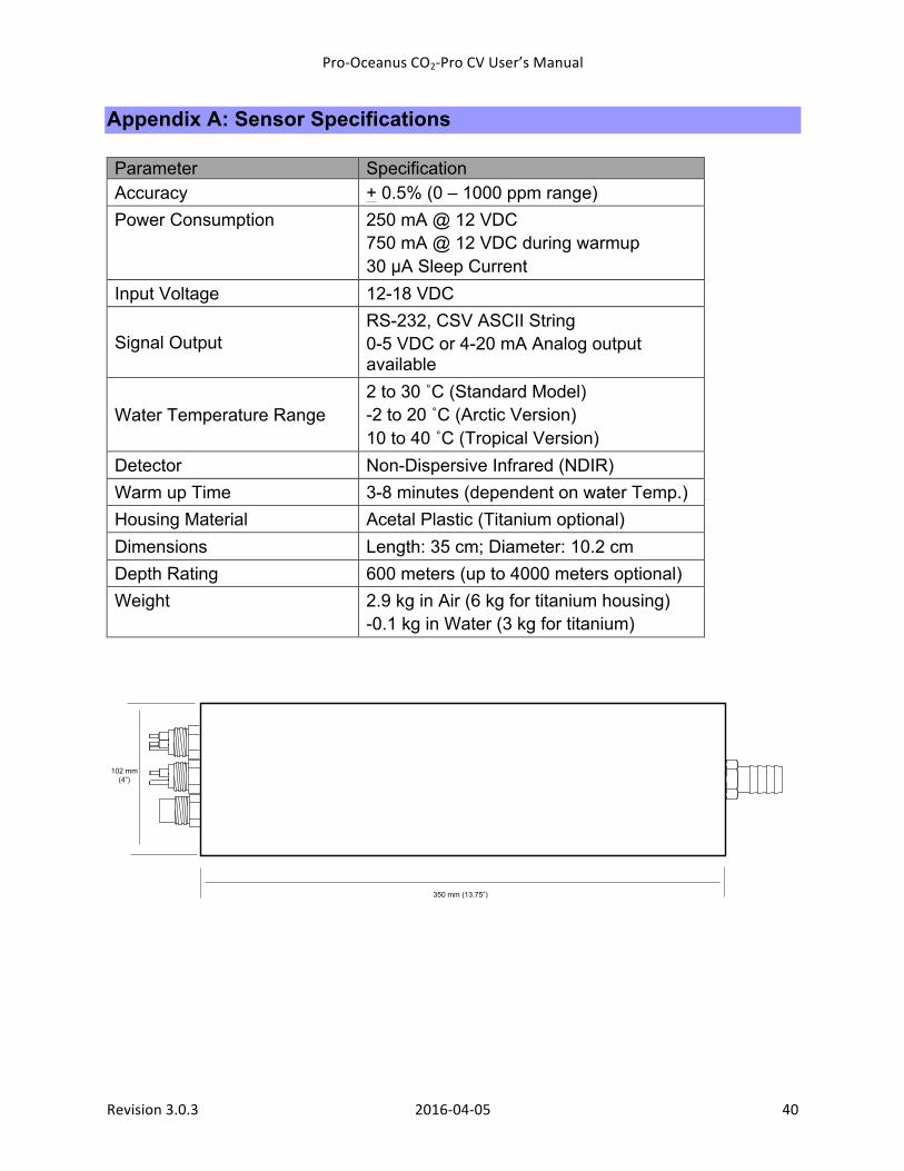
Appendix A: Sensor Specifications Parameter Specification Accuracy + 0.5% (0 – 1000 ppm range) Power Consumption 250 mA @ 12 VDC
750 mA @ 12 VDC during warmup 30 µA Sleep Current
Input Voltage 12-18 VDC
Signal Output RS-232, CSV ASCII String 0-5 VDC or 4-20 mA Analog output available
Water Temperature Range 2 to 30 ˚C (Standard Model) -2 to 20 ˚C (Arctic Version) 10 to 40 ˚C (Tropical Version)
Detector Non-Dispersive Infrared (NDIR) Warm up Time 3-8 minutes (dependent on water Temp.) Housing Material Acetal Plastic (Titanium optional) Dimensions Length: 35 cm; Diameter: 10.2 cm Depth Rating 600 meters (up to 4000 meters optional) Weight 2.9 kg in Air (6 kg for titanium housing)
-0.1 kg in Water (3 kg for titanium)
102 mm(4”)
350 mm (13.75”)
Pro-‐Oceanus CO2-‐Pro CV User’s Manual
Revision 3.0.3 2016-‐04-‐05 41
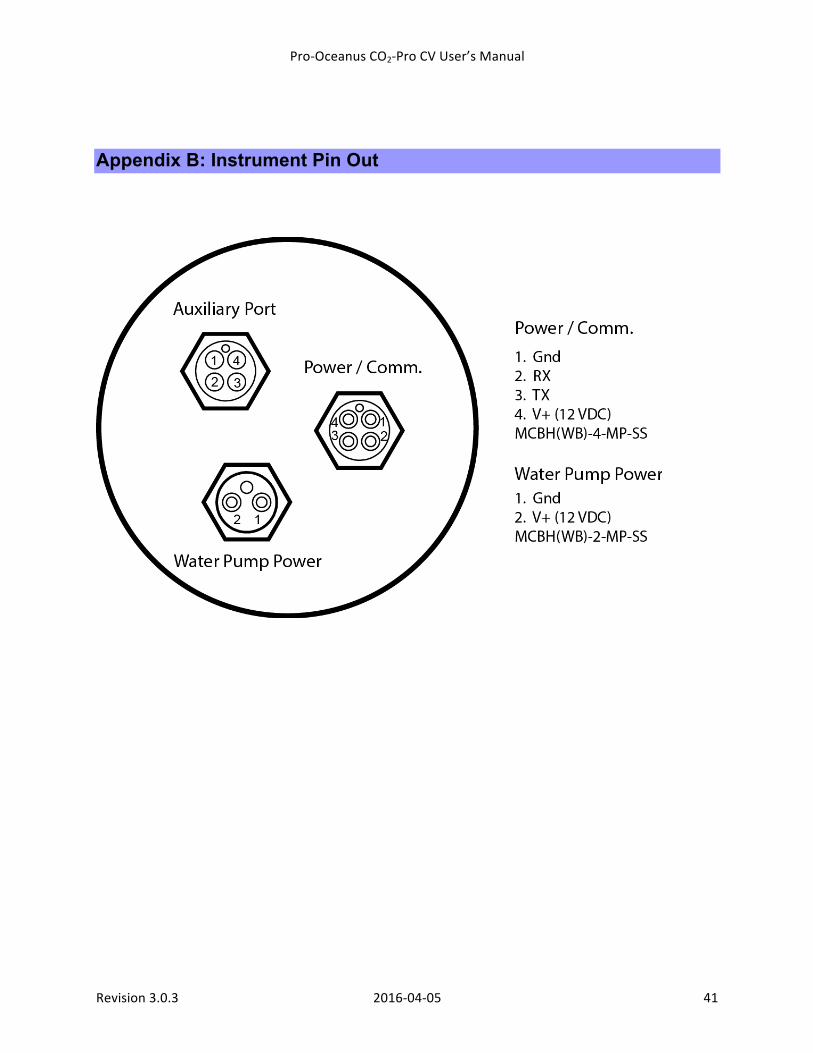
Appendix B: Instrument Pin Out
Pro-‐Oceanus CO2-‐Pro CV User’s Manual
Revision 3.0.3 2016-‐04-‐05 42
Appendix C: Pass-through Mode commands
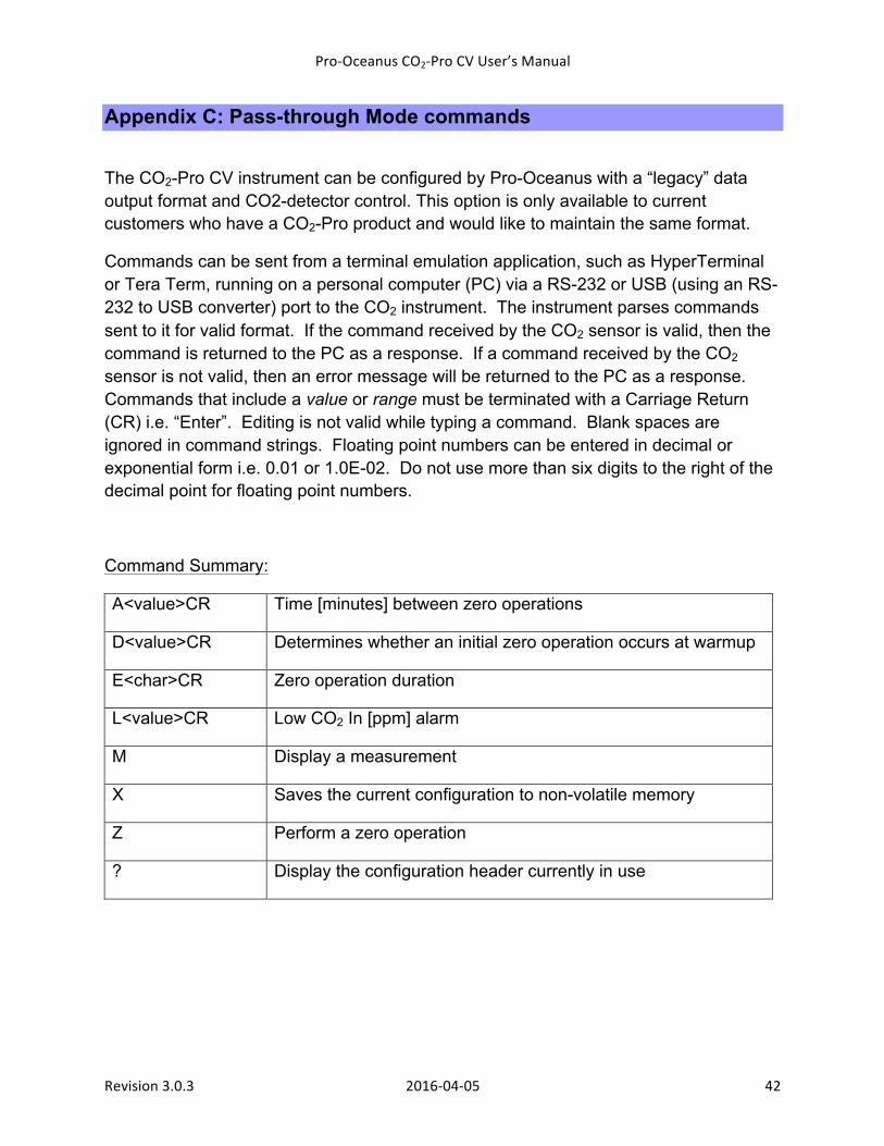
The CO2-Pro CV instrument can be configured by Pro-Oceanus with a “legacy” data output format and CO2-detector control. This option is only available to current customers who have a CO2-Pro product and would like to maintain the same format.
Commands can be sent from a terminal emulation application, such as HyperTerminal or Tera Term, running on a personal computer (PC) via a RS-232 or USB (using an RS-232 to USB converter) port to the CO2 instrument. The instrument parses commands sent to it for valid format. If the command received by the CO2 sensor is valid, then the command is returned to the PC as a response. If a command received by the CO2 sensor is not valid, then an error message will be returned to the PC as a response. Commands that include a value or range must be terminated with a Carriage Return (CR) i.e. “Enter”. Editing is not valid while typing a command. Blank spaces are ignored in command strings. Floating point numbers can be entered in decimal or exponential form i.e. 0.01 or 1.0E-02. Do not use more than six digits to the right of the decimal point for floating point numbers.
Command Summary:
A<value>CR Time [minutes] between zero operations
D<value>CR Determines whether an initial zero operation occurs at warmup
E<char>CR Zero operation duration
L<value>CR Low CO2 In [ppm] alarm
M Display a measurement
X Saves the current configuration to non-volatile memory
Z Perform a zero operation
? Display the configuration header currently in use
Pro-‐Oceanus CO2-‐Pro CV User’s Manual
Revision 3.0.3 2016-‐04-‐05 43
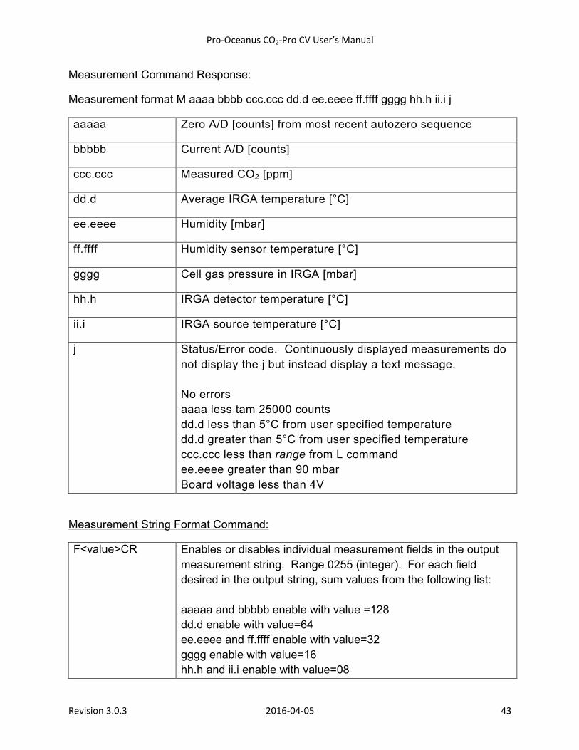
Measurement Command Response:
Measurement format M aaaa bbbb ccc.ccc dd.d ee.eeee ff.ffff gggg hh.h ii.i j
aaaaa Zero A/D [counts] from most recent autozero sequence
bbbbb Current A/D [counts]
ccc.ccc Measured CO2 [ppm]
dd.d Average IRGA temperature [°C]
ee.eeee Humidity [mbar]
ff.ffff Humidity sensor temperature [°C]
gggg Cell gas pressure in IRGA [mbar]
hh.h IRGA detector temperature [°C]
ii.i IRGA source temperature [°C]
j Status/Error code. Continuously displayed measurements do not display the j but instead display a text message. No errors aaaa less tam 25000 counts dd.d less than 5°C from user specified temperature dd.d greater than 5°C from user specified temperature ccc.ccc less than range from L command ee.eeee greater than 90 mbar Board voltage less than 4V
Measurement String Format Command:
F<value>CR Enables or disables individual measurement fields in the output measurement string. Range 0255 (integer). For each field desired in the output string, sum values from the following list: aaaaa and bbbbb enable with value =128 dd.d enable with value=64 ee.eeee and ff.ffff enable with value=32 gggg enable with value=16 hh.h and ii.i enable with value=08
Pro-‐Oceanus CO2-‐Pro CV User’s Manual
Revision 3.0.3 2016-‐04-‐05 44
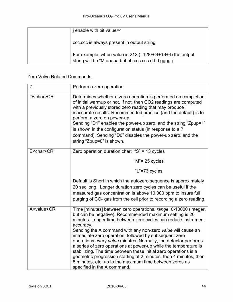
j enable with bit value=4 ccc.ccc is always present in output string For example, when value is 212 (=128+64+16+4) the output string will be “M aaaaa bbbbb ccc.ccc dd.d gggg j”
Zero Valve Related Commands:
Z Perform a zero operation
D<char>CR Determines whether a zero operation is performed on completion of initial warmup or not. If not, then CO2 readings are computed with a previously stored zero reading that may produce inaccurate results. Recommended practice (and the default) is to perform a zero on power-up. Sending “D1” enables the power-up zero, and the string “Zpup=1” is shown in the configuration status (in response to a ? command). Sending “D0” disables the power-up zero, and the string “Zpup=0” is shown.
E<char>CR Zero operation duration char: “S” = 13 cycles
“M”= 25 cycles
“L”=73 cycles
Default is Short in which the autozero sequence is approximately 20 sec long. Longer duration zero cycles can be useful if the measured gas concentration is above 10,000 ppm to insure full purging of CO2 gas from the cell prior to recording a zero reading.
A<value>CR Time [minutes] between zero operations. range: 0-10000 (integer, but can be negative). Recommended maximum setting is 20 minutes. Longer time between zero cycles can reduce instrument accuracy. Sending the A command with any non-zero value will cause an immediate zero operation, followed by subsequent zero operations every value minutes. Normally, the detector performs a series of zero operations at power-up while the temperature is stabilizing. The time between these initial zero operations is a geometric progression starting at 2 minutes, then 4 minutes, then 8 minutes, etc. up to the maximum time between zeros as specified in the A command.
Pro-‐Oceanus CO2-‐Pro CV User’s Manual
Revision 3.0.3 2016-‐04-‐05 45
It is possible to disable these progressive zero operations during startup by setting the value in the A command to a negative number. For example, “A-10” will disable the progressive zeros if the configuration is saved with the X command, so that on the next power-up, the first timed zero occurs after 10 minutes (there still can be a power-up zero immediately after warm-up is complete, depending on the setting of the D command and Zpup). A0 disables all timed zeros and all progressive zeros. See D command to also disable the power-up zero. This is not a recommended setting.
CO2 Related Commands:
C<value>CR Number of digits to the right of the decimal point for ccc.ccc. range: 0-3 (integer).
L<value>CR Low CO2 in [ppm] alarm. range: 0-100000 (floating point). In typical environmental applications, a CO2 reading in measurement mode of less than 350 ppm indicates a problem with the autozero operation, such as the zero gas is not connected, the CO2 absorber is exhausted, or the zero valve is not operating. The Low CO2 Error helps identify those common problems before the abnormal readings can affect subsequent data. This value can be adjusted to suit a particular operating environment or can be eliminated completely by setting the value to 0.
B<value>CR Averaging limit for CO2 running average. Normally, an exponential running average algorithm is implemented with a rime response to a step change of 5.6 seconds to 66% of final value and 26.4 seconds to 99% of final value. If a new reading differs from the current running average by more than the Averaging Limit value, a new running average is begun. Thus when the CO2 concentration is changing rapidly, the average is eliminated and the instrument can track changes at the basic instrument data rate of 1.6 seconds. When the Averaging Limit value is set to 0, no running average is performed. The default Averaging Limit value is 0.3% of full scale or 6 ppm for a 2000 ppm instrument. The running averaging is applied to both digital
Pro-‐Oceanus CO2-‐Pro CV User’s Manual
Revision 3.0.3 2016-‐04-‐05 46
and analog output signals.
Other Commands:
? Display the CO2 Detector configuration currently in use (the volatile memory working area).
X Saves the current configuration to non-volatile memory. Use this command to save configuration changes before powering off the CO2 detector
At CO2 detector power on, the non-volatile memory working area is copied to the volatile memory working area.
Command Files:
Any of the commands can be included in a text file created by a program such as Microsoft Notepad. This file can be downloaded to the CO2 detector by using the HyperTerminal menu item Transfer>Send Text File… Command a zero operation before transferring the command file to ensure the maximum time until the next zero operation. Ensure that all lines including the last end with a carriage return and line feed (LF). Command files may include comments in the following format: ;commentCRLF.
The following additional serial communication setup parameters should be set in ASCII Setup>ASCII Sending when sending command files to the CO2 detector:
- Do not send line ends with line feeds - Do not echo typed characters locally - Character delay: 10 milliseconds
Pro-‐Oceanus CO2-‐Pro CV User’s Manual
Revision 3.0.3 2016-‐04-‐05 47
Appendix D: Material Safety Data Sheets
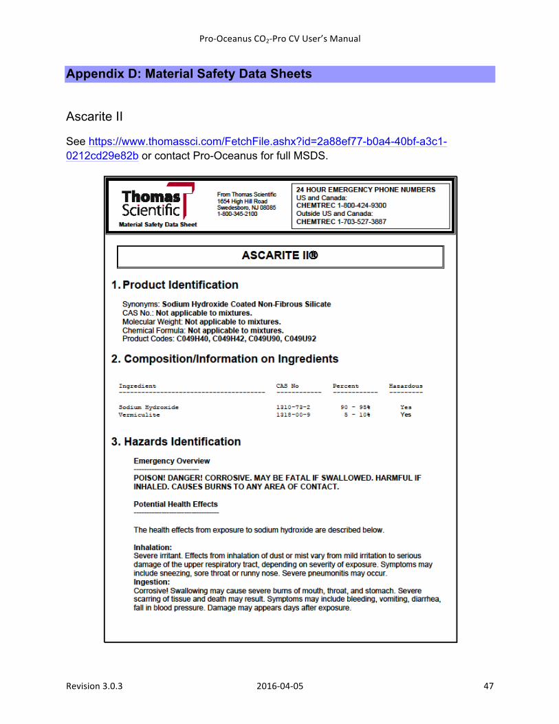
Ascarite II
See https://www.thomassci.com/FetchFile.ashx?id=2a88ef77-b0a4-40bf-a3c1-0212cd29e82b or contact Pro-Oceanus for full MSDS.
Pro-‐Oceanus CO2-‐Pro CV User’s Manual
Revision 3.0.3 2016-‐04-‐05 48
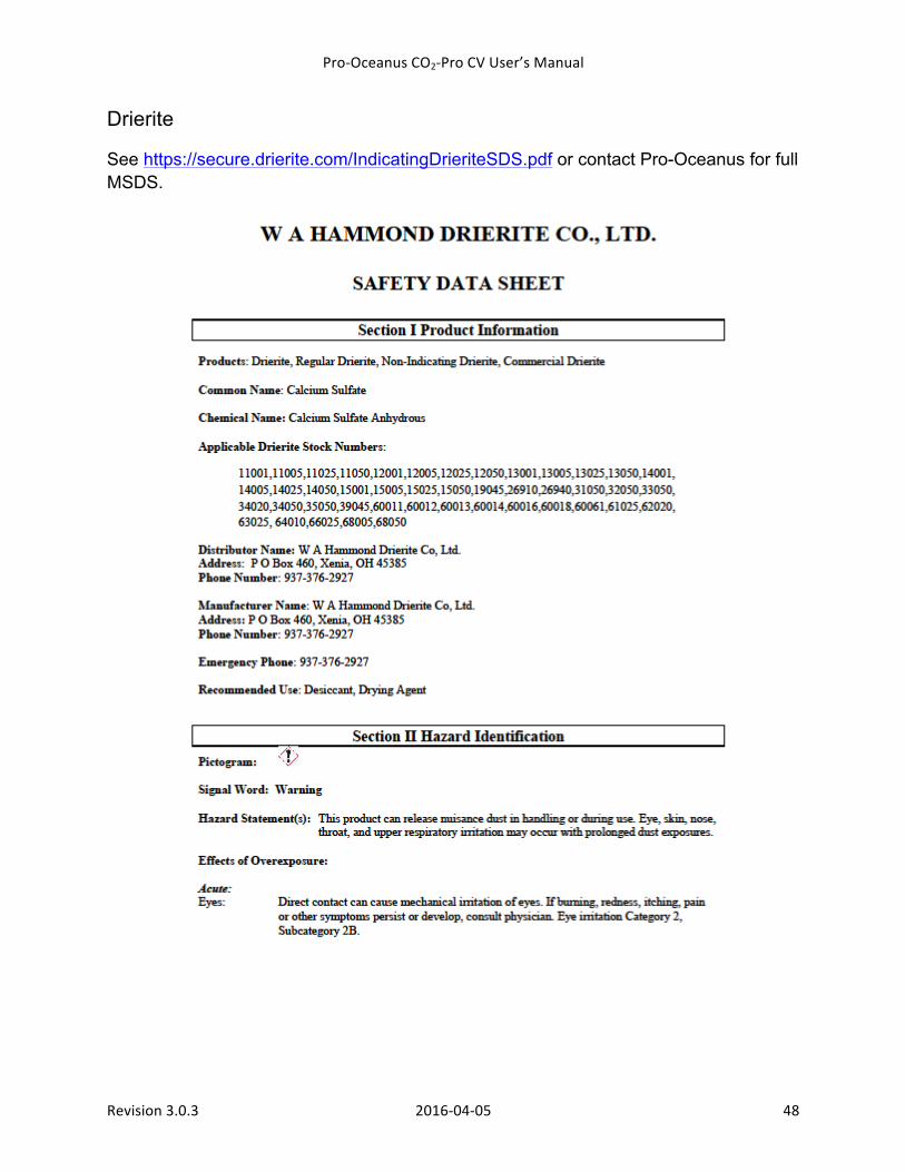
Drierite
See https://secure.drierite.com/IndicatingDrieriteSDS.pdf or contact Pro-Oceanus for full MSDS.
Pro-‐Oceanus CO2-‐Pro CV User’s Manual
Revision 3.0.3 2016-‐04-‐05 49
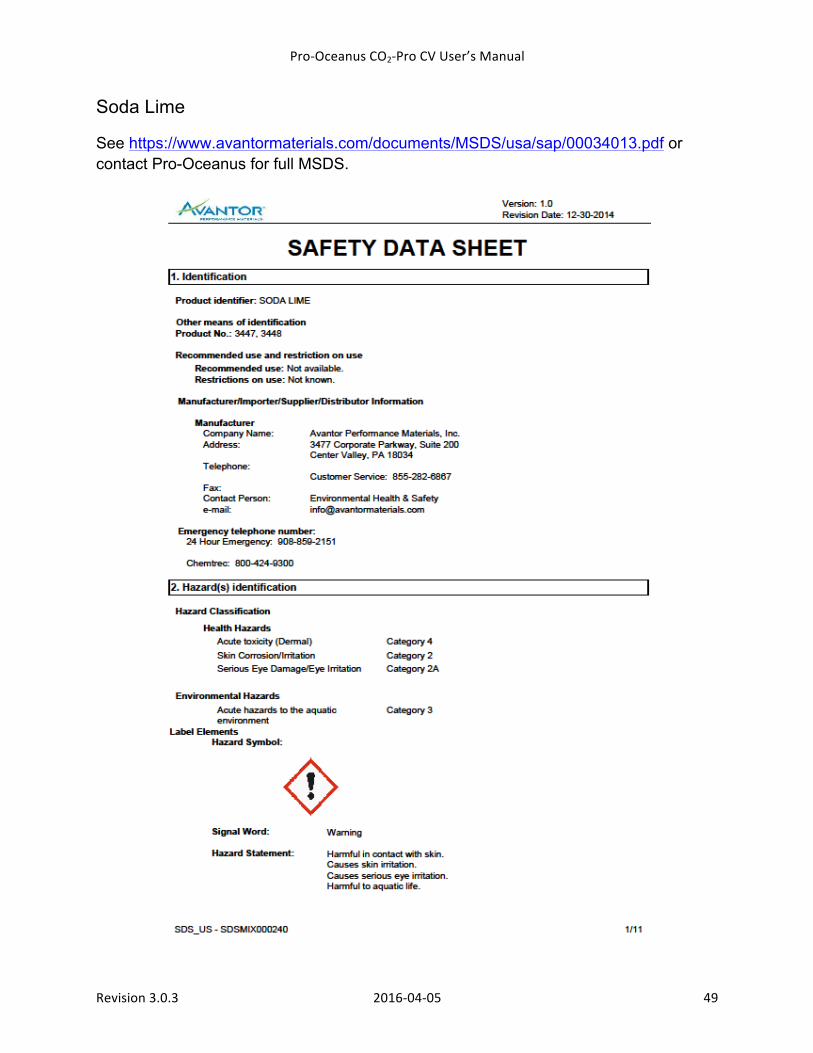
Soda Lime
See https://www.avantormaterials.com/documents/MSDS/usa/sap/00034013.pdf or contact Pro-Oceanus for full MSDS.


![ΑΝΤΙΣΤΡΟΦΟ [902] ΛΕΞΙΚΟ [ΜΕΣΑΙΩΝΙΚΟ ΓΛΩΣΣΑΡΙΟ] [Α-Ω] [902] ΜΕΡΣΙΟΥ.pdf](https://img.pdfslide.net/doc/110x75/577c7d991a28abe0549f5d01/-902--578131b7b4359.jpg)