Embed Size (px)
Citation preview
CO2 Storage and CO2 EOR – comparison & standardisation
Professor Niels Peter Christensen
Chief Geologist
7th IEA International CCS
Regulatory Network Meeting
22 – 23 April 2015, IEA Paris
Storage in saline aquifers
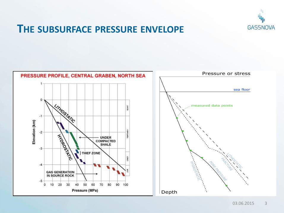
THE SUBSURFACE PRESSURE ENVELOPE
03.06.2015 3
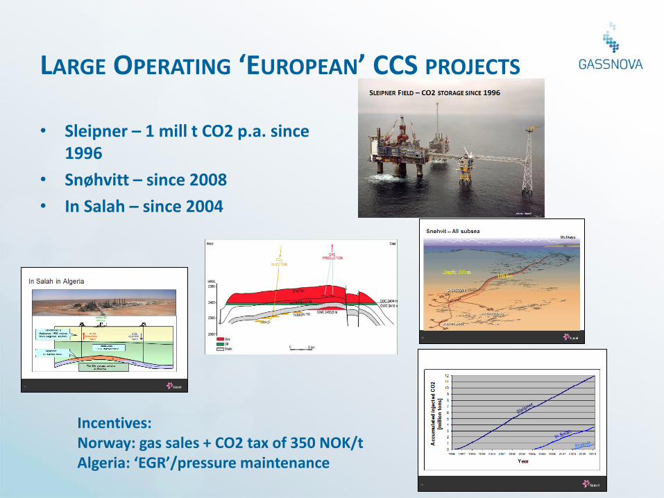
LARGE OPERATING ‘EUROPEAN’ CCS PROJECTS
• Sleipner – 1 mill t CO2 p.a. since 1996
• Snøhvitt – since 2008
• In Salah – since 2004
Incentives: Norway: gas sales + CO2 tax of 350 NOK/t Algeria: ‘EGR’/pressure maintenance
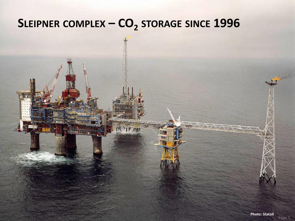
Photo: Statoil
SLEIPNER COMPLEX – CO2 STORAGE SINCE 1996
Page 5
6
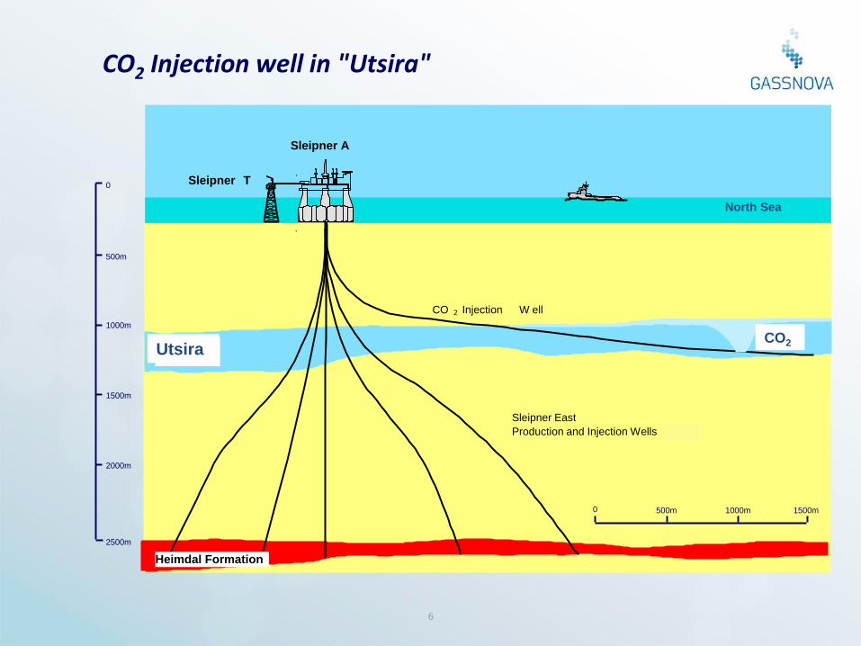
CO2 Injection well in "Utsira"
Sleipner A
Sleipner T
Utsir a
F or
Heimdal Formation
Sleipner East
Production and Injection Wells W ells
CO 2
CO 2 Injection W ell
1000m
2000m
2500m
0
500m
1500m
1000m 0 500m 1500m
Utsira CO2
North Sea
Class
ificati
on:
Intern
al
2010-
04-14
7
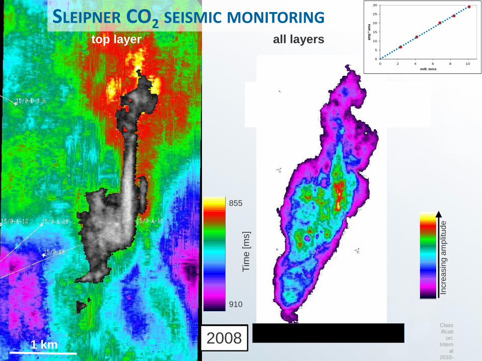
1999 2001 2002 2004 2006 2008 1 km
top layer all layers
Incre
asin
g a
mp
litu
de
SLEIPNER CO2 SEISMIC MONITORING
855
910
Tim
e [m
s]
0
5
10
15
20
25
30
0 2 4 6 8 10
mill. tons
am
p *
are
a
8
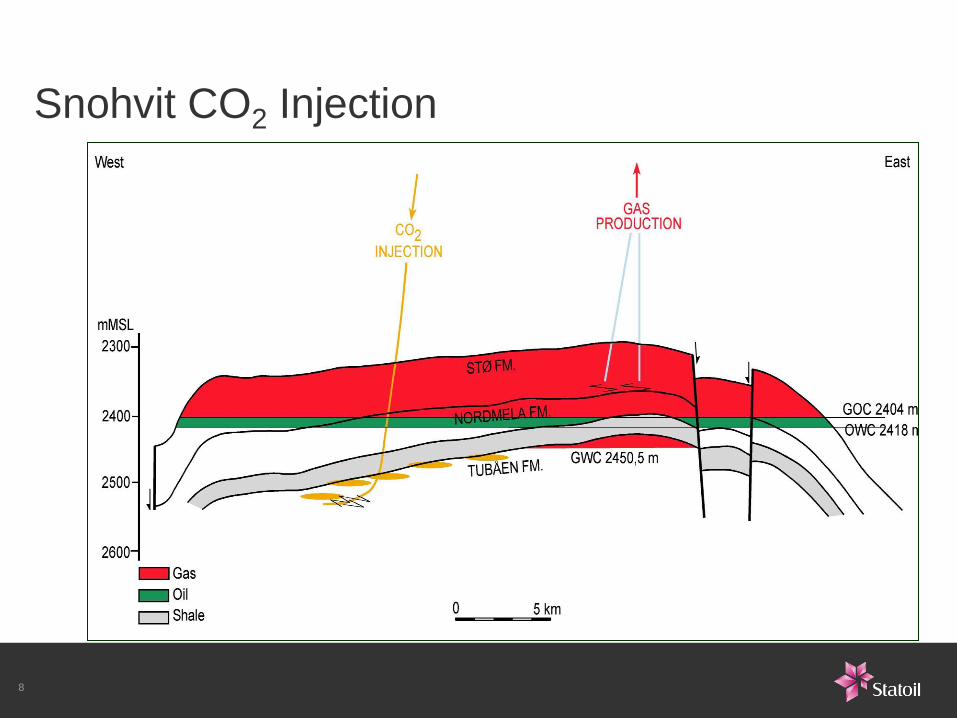
Snohvit CO2 Injection
9
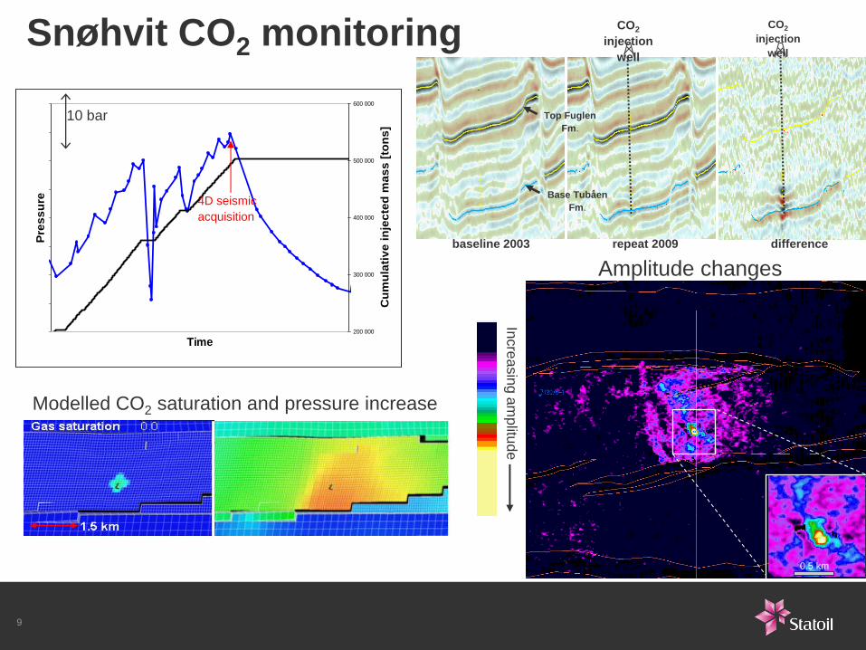
Snøhvit CO2 monitoring
Top Fuglen
Fm.
Base Tubåen
Fm.
CO2
injection
well
CO2
injection
well
baseline 2003 repeat 2009 difference
0.5 km
Incre
asin
g a
mp
litud
e
Amplitude changes
Modelled CO2 saturation and pressure increase
Time
Pre
ss
ure
200 000
300 000
400 000
500 000
600 000
Cu
mu
lati
ve
in
jec
ted
ma
ss
[to
ns
]
4D seismic
acquisition
10 bar
10
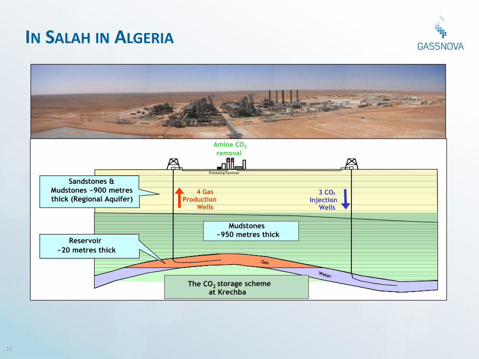
IN SALAH IN ALGERIA
Carboniferous Reservoir
~20 metres thick
Carboniferous Mudstones
~950 metres thick
Cretaceous Sandstones &
Mudstones ~900 metres
thick (Regional Aquifer) 4 Gas Production
Wells
3 CO 2
Injection Wells
Processing Facilities
Amine CO2
Removal
The CO 2 Storage Scheme at Krechba
Carboniferous Reservoir
~20 metres thick
Carboniferous Mudstones
~950 metres thick
Cretaceous Sandstones &
Mudstones ~900 metres
thick (Regional Aquifer) 4 Gas Production
Wells
3 CO 2
Injection Wells
Processing Facilities
Amine CO2
Removal
The CO 2 Storage Scheme at Krechba
Carboniferous Reservoir
~20 metres thick
Carboniferous Mudstones
~950 metres thick
Cretaceous Sandstones &
Mudstones ~900 metres
thick (Regional Aquifer) 4 Gas Production
Wells
3 CO 2
Injection Wells
Processing Facilities
Amine CO2
Removal
Carboniferous Reservoir
~20 metres thick
Carboniferous Mudstones
~950 metres thick
Cretaceous Sandstones &
Mudstones ~900 metres
thick (Regional Aquifer) 4 Gas Production
Wells
3 CO 2
Injection Wells
Processing Facilities
Amine CO2
Removal
Carboniferous Reservoir
~20 metres thick
Carboniferous Mudstones
~950 metres thick
Cretaceous Sandstones &
Mudstones ~900 metres
thick (Regional Aquifer) 4 Gas Production
Wells
3 CO 2
Injection Wells
Processing Facilities
Amine CO2
Removal
The CO 2 Storage Scheme at Krechba
Carboniferous Reservoir
~20 metres thick
Carboniferous Mudstones
~950 metres thick
Cretaceous Sandstones &
Mudstones ~900 metres
thick (Regional Aquifer) 4 Gas Production
Wells
3 CO 2
Injection Wells
Processing Facilities
Amine CO2
Removal
The CO 2 Storage Scheme at Krechba
Carboniferous Reservoir
~20 metres thick
Cretaceous Sandstones &
Mudstones ~900 metres
thick (Regional Aquifer) 4 Gas Production
Wells
3 CO 2
Injection Wells
Processing Facilities
The CO 2 Storage Scheme at Krechba
Carboniferous Reservoir
~20 metres thick
Cretaceous Sandstones &
Mudstones ~900 metres
thick (Regional Aquifer) 4 Gas Production
Wells
3 CO 2
Injection Wells
Processing Facilities
Amine CO2
removal
Reservoir
~20 metres thick
Mudstones ~950 metres thick
Sandstones & Mudstones ~900 metres thick (Regional Aquifer)
4 Gas Production
Wells
3 CO 2
Injection Wells
Processing Facilities
The CO2 storage scheme at Krechba
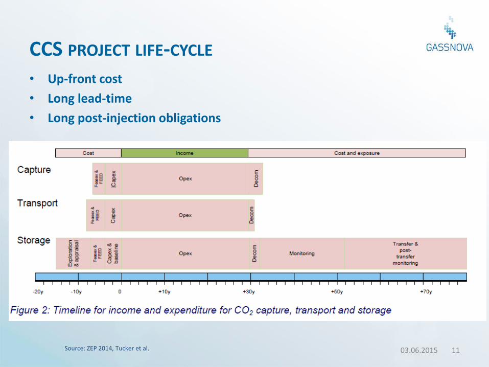
CCS PROJECT LIFE-CYCLE
• Up-front cost
• Long lead-time
• Long post-injection obligations
03.06.2015 11 Source: ZEP 2014, Tucker et al.
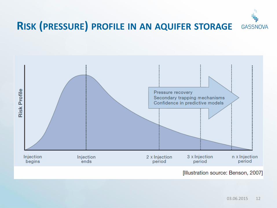
RISK (PRESSURE) PROFILE IN AN AQUIFER STORAGE
03.06.2015 12
Storage as part of CO2 EOR
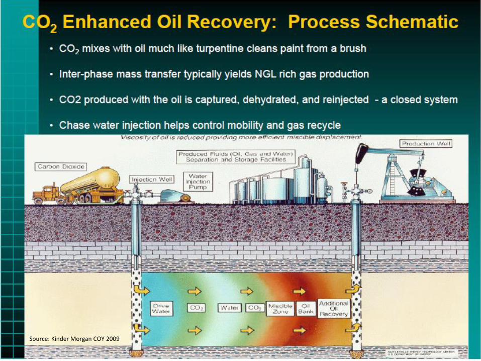
Source: Kinder Morgan COY 2009
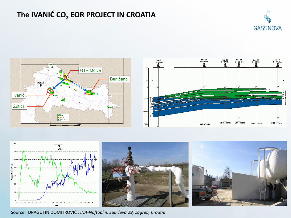
The IVANIĆ CO2 EOR PROJECT IN CROATIA
Source: DRAGUTIN DOMITROVIĆ , INA-Naftaplin, Šubićeva 29, Zagreb, Croatia
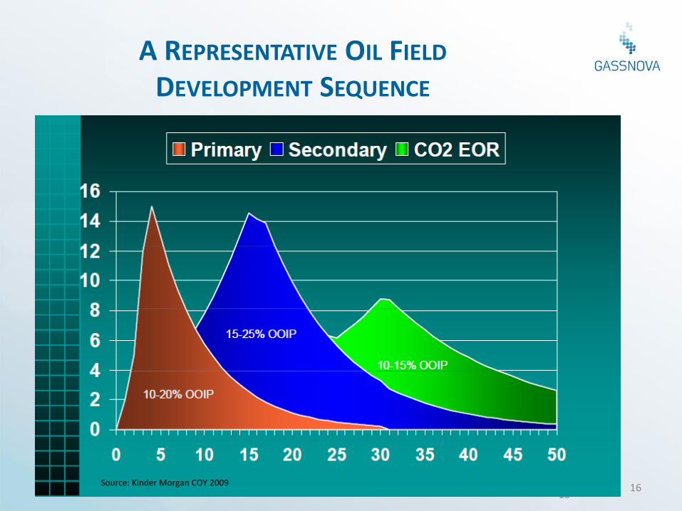
A REPRESENTATIVE OIL FIELD DEVELOPMENT SEQUENCE
03.06.2015
16 Source: Kinder Morgan COY 2009
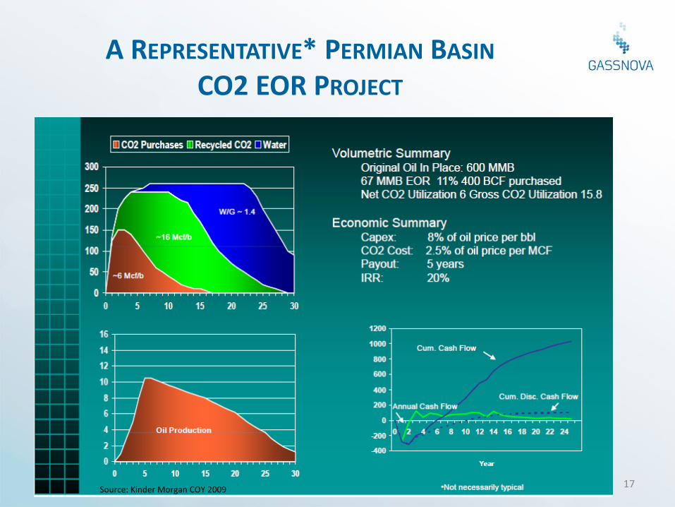
A REPRESENTATIVE* PERMIAN BASIN CO2 EOR PROJECT
03.06.2015 17 Source: Kinder Morgan COY 2009
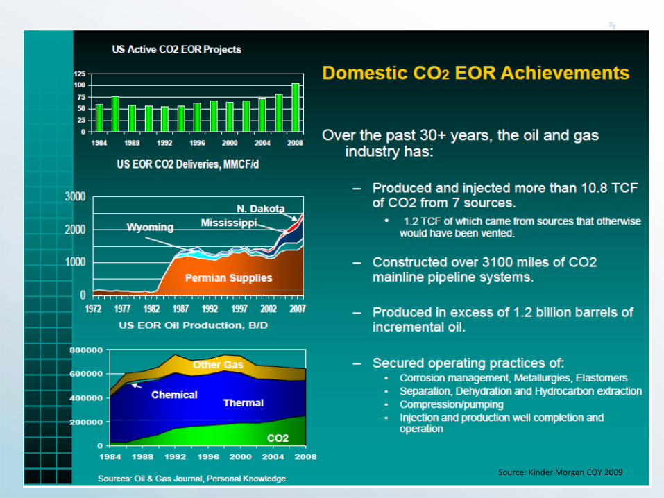
03.06.2015 18 Source: Kinder Morgan COY 2009
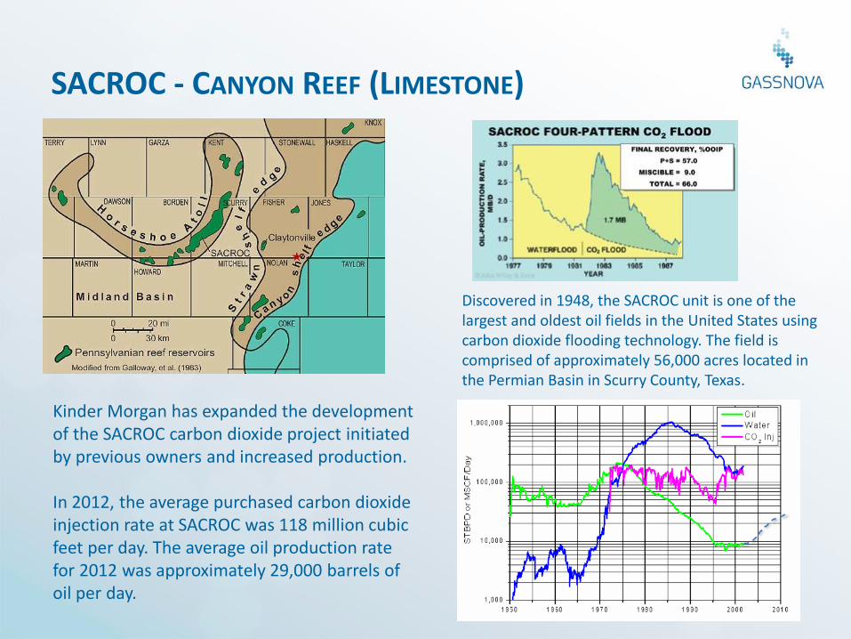
SACROC - CANYON REEF (LIMESTONE)
Kinder Morgan has expanded the development of the SACROC carbon dioxide project initiated by previous owners and increased production. In 2012, the average purchased carbon dioxide injection rate at SACROC was 118 million cubic feet per day. The average oil production rate for 2012 was approximately 29,000 barrels of oil per day.
Discovered in 1948, the SACROC unit is one of the largest and oldest oil fields in the United States using carbon dioxide flooding technology. The field is comprised of approximately 56,000 acres located in the Permian Basin in Scurry County, Texas.
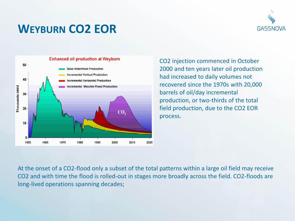
WEYBURN CO2 EOR
At the onset of a CO2-flood only a subset of the total patterns within a large oil field may receive CO2 and with time the flood is rolled-out in stages more broadly across the field. CO2-floods are long-lived operations spanning decades;
CO2 injection commenced in October 2000 and ten years later oil production had increased to daily volumes not recovered since the 1970s with 20,000 barrels of oil/day incremental production, or two-thirds of the total field production, due to the CO2 EOR process.
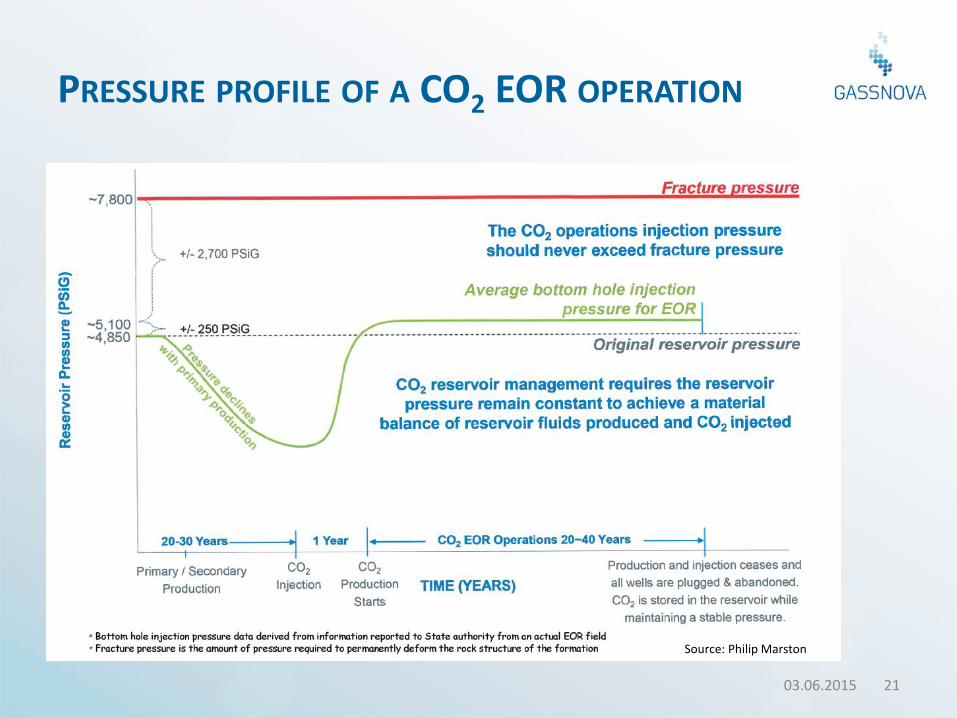
PRESSURE PROFILE OF A CO2 EOR OPERATION
03.06.2015 21
Source: Philip Marston
Standardisation: ISO TC 265
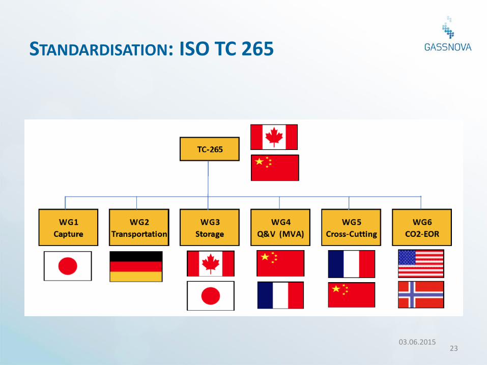
STANDARDISATION: ISO TC 265
03.06.2015 23
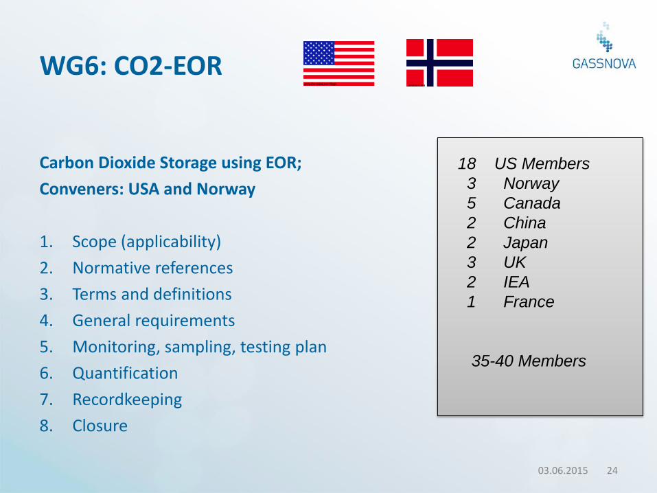
WG6: CO2-EOR
Carbon Dioxide Storage using EOR;
Conveners: USA and Norway
1. Scope (applicability)
2. Normative references
3. Terms and definitions
4. General requirements
5. Monitoring, sampling, testing plan
6. Quantification
7. Recordkeeping
8. Closure
03.06.2015 24
18 US Members
3 Norway
5 Canada
2 China
2 Japan
3 UK
2 IEA
1 France
35-40 Members
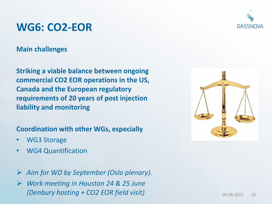
WG6: CO2-EOR
Main challenges
Striking a viable balance between ongoing commercial CO2 EOR operations in the US, Canada and the European regulatory requirements of 20 years of post injection liability and monitoring
Coordination with other WGs, especially
• WG3 Storage
• WG4 Quantification
Aim for WD by September (Oslo plenary).
Work meeting in Houston 24 & 25 June (Denbury hosting + CO2 EOR field visit) 03.06.2015 25
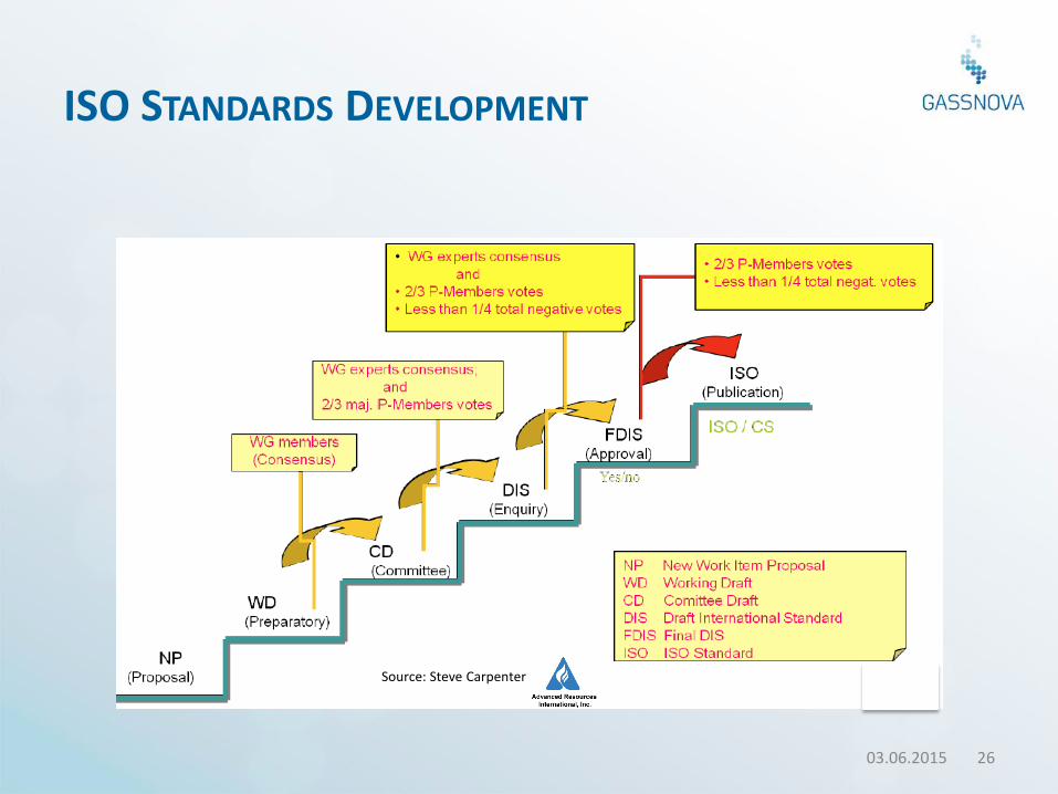
ISO STANDARDS DEVELOPMENT
03.06.2015 26
Source: Steve Carpenter
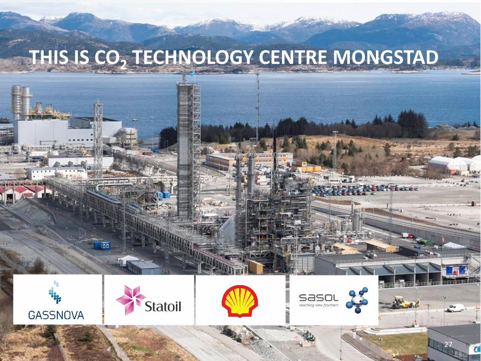
THIS IS CO2 TECHNOLOGY CENTRE MONGSTAD
27
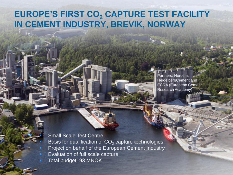
EUROPE’S FIRST CO2 CAPTURE TEST FACILITY
IN CEMENT INDUSTRY, BREVIK, NORWAY
Small Scale Test Centre
Basis for qualification of CO2 capture technologies
Project on behalf of the European Cement Industry
Evaluation of full scale capture
Total budget: 93 MNOK
Partners: Norcem,
HeidelbergCement and
ECRA (European Cement
Research Academy)
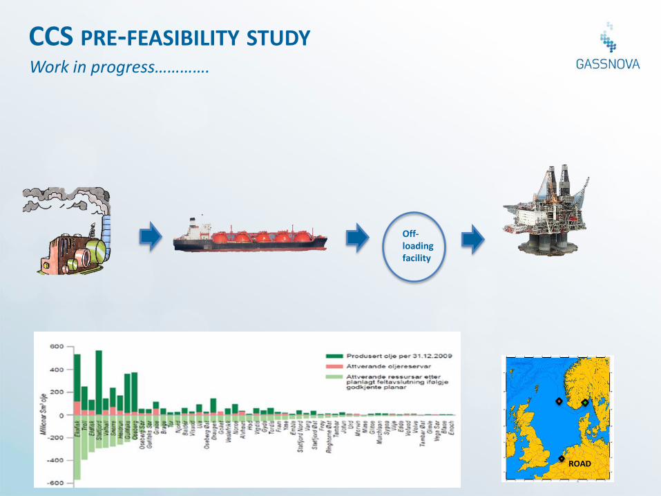
Work in progress………….
CCS PRE-FEASIBILITY STUDY
Off-loading facility
ROAD
THANK YOU! Niels Peter Christensen [email protected] Gassnova SF www.gassnova.no/en CLIMIT program www.climit.no/en