Embed Size (px)
Citation preview

Bureau of Mines Information Circular11 987
Coal Mine Bumps: Five Case Studies in the Eastern United States
By Alan A. Campoli, Carla A. Kertis, and Claude A. Goode
UNITED STATES DEPARTMENT OF THE INTERIOR

Information Circular 91 49
Coal Mine Bumps: Five Case Studies in the Eastern United States
By Alan A. Campoli, Carla A. Kertis, and Claude A. Goode
UNITED STATES DEPARTMENT OF THE INTERIOR Donald Paul Hodel, Secretary
BUREAU OF MINES David S. Brown, Acting Director

Library of Congress Cataloging-in-Publication Data
Campoli, A. A. (Alan A.) Coal mine bumps.
(Information circular ; 9149)
Bibliography: p. 34.
Supt. of Docs nu : I 'LS 27:9149.
1. Coal mines and rn~n~ng-United States-Accidents. 2. Rock bursts. I. Kertis, Carla A. 11. Goode, Claude A. 111. Title. IV. Series: Information circular (United States. Bureau of Mines) ; 9149.

Page Abstract . . . . . . . . . . . . . . . . . . . . . . . . . . . . . . . . . . . . 1 Introduction . . . . . . . . . . . . . . . . . . . . . . . . . . . . . . . . 2 Acknowledgments . . . . . . . . . . . . . . . . . . . . . . . . . . . 2
. . . . . . . . . . . Pillar loading and bump mechanisms 2 Case studies . . . . . . . . . . . . . . . . . . . . . . . . . . . . . . . . 5
Mine1 . . . . . . . . . . . . . . . . . . . . . . . . . . . . . . . . . . . 5 . . . . . . . . . . . . . . . . . Stratigraphic relationships 5
Structural setting and overburden thickness . . 5 Bump occurrence . . . . . . . . . . . . . . . . . . . . . . . . . 5
Mine2 . . . . . . . . . . . . . . . . . . . . . . . . . . . . . . . . . . . 13 Stratigraphic relationships . . . . . . . . . . . . . . . . . 13 Structural setting and overburden thickness . . 14 Bump occurrence . . . . . . . . . . . . . . . . . . . . . . . . . 17
Mine3 . . . . . . . . . . . . . . . . . . . . . . . . . . . . . . . . . . . 19 . . . . . . . . . . . . . . . . . Stratigraphic relationships 19
Structural setting and overburden thickness . . Bump occurrence . . . . . . . . . . . . . . . . . . . . . . . . .
. . . . . . . . . . . . . . . . . . . . . . . . Longwall mining Room-and-pillar mining . . . . . . . . . . . . : . . . . .
. . . . . . . . . . . . . . . . . . . . . . . . . . . . . . . . . . . Mine4 Stratigraphic relationships . . . . . . . . . . . . . . . . . Structural setting and overburden thickness . . Bump occurrence . . . . . . . . . . . . . . . . . . . . . . . . .
Mine5 . . . . . . . . . . . . . . . . . . . . . . . . . . . . . . . . . . . Stratigraphic relationships . . . . . . . . . . . . . . . . . Structural setting and overburden thickness . . Bump occurrence . . . . . . . . . . . . . . . . . . . . . . . . .
Conclusions and recommendations . . . . . . . . . . . . . . References . . . . . . . . . . . . . . . . . . . . . . . . . . . . . . . . . .
Page 20 22 22 23 24 24 24 28 29 29 30 30 34 34
ILLUSTRATIONS
1 . Adjustment of stress around a single entry . . . . . . . . . . . . . . . . . . . . . . . . . . . . . . . . . . . . . . . . . . . . . . . . . . . . . . 3 2 . Adjustment of stress around a wide pillar . . . . . . . . . . . . . . . . . . . . . . . . . . . . . . . . . . . . . . . . . . . . . . . . . . . . . . . 3 3 . Adjustment of stress around a narrow pillar . . . . . . . . . . . . . . . . . . . . . . . . . . . . . . . . . . . . . . . . . . . . . . . . . . . . . 4 4 . Adjustment of stress due to the yielding of a narrow pillar . . . . . . . . . . . . . . . . . . . . . . . . . . . . . . . . . . . . . . . . . 4 5 . Idealized diagram of core confinement loading of a critical size pillar . . . . . . . . . . . . . . . . . . . . . . . . . . . . . . . . 4 6 . Generalized stratigraphic column for mine 1 . . . . . . . . . . . . . . . . . . . . . . . . . . . . . . . . . . . . . . . . . . . . . . . . . . . . . 5 7 . Sandstone thickness map of Eckman Sandstone, which immediately overlies Pocahontas No . 4 Coalbed,
mine1 . . . . . . . . . . . . . . . . . . . . . . . . . . . . . . . . . . . . . . . . . . . . . . . . . . . . . . . . . . . . . . . . . . . . . . . . . . . . . . . . . . 6 8 . Structure contour map for mine 1, drawn from elevation of top of Pocahontas No . 4 Coalbed . . . . . . . . . . . . 7
. . . . . . . . . . . . . . . . . . . . . . . . . . . . . . . . . . . . . . . . . . . . . . . . . . . . . . . . . . . . . . . . . . . 9 . Overburden map for mine 1 8 10 . Plan view of area of bump accident on October 18, 1983, mine 1 . . . . . . . . . . . . . . . . . . . . . . . . . . . . . . . . . . . . 9
. . . . . . . . . . . . . . . . . . . . . . . . . . . . . . . . . . . . . . 11 . Plan view of mining sequence prior to bump accident, mine 1 10 12 . Idealized diagram of abutment force transfer in area of bump accident, mine 1 . . . . . . . . . . . . . . . . . . . . . . . . 10 13 . Location of hydraulic load cells in relation to area of bump accident, mine 1 . . . . . . . . . . . . . . . . . . . . . . . . . . 11 14 . Progress of mining maps, for mining periods 1 through 6, of hydraulic load cell readings, mine 1 . . . . . . . . 12 15 . Graphical display of hydraulic load cell readings, for mining periods 1 through 6, mine 1 . . . . . . . . . . . . . . . 13 16 . Generalized stratigraphic column for mine 2 . . . . . . . . . . . . . . . . . . . . . . . . . . . . . . . . . . . . . . . . . . . . . . . . . . . . . 13 17 . Sandstone thickness map of Eckman Sandstone, which immediately overlies Pocahontas No . 4 Coalbed,
mine2 . . . . . . . . . . . . . . . . . . . . . . . . . . . . . . . . . . . . . . . . . . . . . . . . . . . . . . . . . . . . . . . . . . . . . . . . . . . . . . . . . . . . 14 18 . Structure contour map for mine 2, drawn from elevation of top of Pocahontas No . 4 Coalbed . . . . . . . . . . . . 15 19 . Overburden map for mine 2 . . . . . . . . . . . . . . . . . . . . . . . . . . . . . . . . . . . . . . . . . . . . . . . . . . . . . . . . . . . . . . . . . . . 16 20 . Thin-pillar mining method diagram, mine 2 . . . . . . . . . . . . . . . . . . . . . . . . . . . . . . . . . . . . . . . . . . . . . . . . . . . . . 17 21 . Results of auger drilling of bump block left by thin-pillar mining method, mine 2 . . . . . . . . . . . . . . . . . . . . . 18 22 . Thin-pillar mining method as used to retreat old mains located between two gobs, mine 2 . . . . . . . . . . . . . . 19 23 . Generalized stratigraphic column for mine 3 . . . . . . . . . . . . . . . . . . . . . . . . . . . . . . . . . . . . . . . . . . . . . . . . . . . . . . 20 24 . Structure contour map for mine 3, drawn from elevation of top of Pocahonatas No . 3 Coalbed . . . . . . . . . . . 20 25 . Overburden map for mine 3 . . . . . . . . . . . . . . . . . . . . . . . . . . . . . . . . . . . . . . . . . . . . . . . . . . . . . . . . . . . . . . . . . . . . 21 26 . Locations of retreating longwall bump events and overburden thicknesses, mine 3 . . . . . . . . . . . . . . . . . . . . . 22 27 . Plan view of longwall gate road entries and location of bump event, mine 3 . . . . . . . . . . . . . . . . . . . . . . . . . . 22 28 . Plan view of shot-fire softening technique, used on tail entry of longwall gate roads for bump control,
mine 3 . . . . . . . . . . . . . . . . . . . . . . . . . . . . . . . . . . . . . . . . . . . . . . . . . . . . . . . . . . . . . . . . . . . . . . . . . . . . . . . . . . . . . 22 29 . Plan view of modified bump control gate road design, mine 3 . . . . . . . . . . . . . . . . . . . . . . . . . . . . . . . . . . . . . . . 23 30 . Convergence contour map for room-and-pillar retreat mining, mine 3 . . . . . . . . . . . . . . . . . . . . . . . . . . . . . . . . 23 31 . Graph of convergence effects of water infusion of pillar C, mine 3 . . . . . . . . . . . . . . . . . . . . . . . . . . . . . . . . . . . 23 32 . Generalized stratigraphic column for mine 4 . . . . . . . . . . . . . . . . . . . . . . . . . . . . . . . . . . . . . . . . . . . . . . . . . . . . . 24 33 . Sandstone thickness map of Lower Winifrede Sandstone, which immediately overlies Chilton Coalbed,
mine4 . . . . . . . . . . . . . . . . . . . . . . . . . . . . . . . . . . . . . . . . . . . . . . . . . . . . . . . . . . . . . . . . . . . . . . . . . . . . . . . . . . . . . 25 34 . Structure contour map for mine 4, drawn from elevation of top of Chilton Coalbed . . . . . . . . . . . . . . . . . . . . . 26 35 . Overburdenmap for mine 4 . . . . . . . . . . . . . . . . . . . . . . . . . . . . . . . . . . . . . . . . . . . . . . . . . . . . . . . . . . . . . . . . . . . . 27 36 . Pocket-and-wing method mining sequence, mine 4 . . . . . . . . . . . . . . . . . . . . . . . . . . . . . . . . . . . . . . . . . . . . . . . . . 28 37 . Overview of bump accident area, mine 4 . . . . . . . . . . . . . . . . . . . . . . . . . . . . . . . . . . . . . . . . . . . . . . . . . . . . . . . . . 28 38 . Plan view of immediate area of bump accident, mine 4 . . . . . . . . . . . . . . . . . . . . . . . . . . . . . . . . . . . . . . . . . . . . 29

Page 39. Generalized stratigraphic column for mine 5 . . . . . . . . . . . . . . . . . . . . . . . . . . . . . . . . . . . . . . . . . . . . . . . . . . . . . 30 40. Structure contour map for mine 5, drawn from elevation of top of No. 2 Gas Coalbed. . . . . . . . . . . . . . . . . . . 31
. . . . . . . . . . . . . . . . . . . . . . . . . . . . . . . . . . . . . . . . . . . . . . . . . . . . . . . . . . . . . . . . . . . 41. Overburden map for mine 5 32 42. Plan view of area of bump accident, mine 5 . . . . . . . . . . . . . . . . . . . . . . . . . . . . . . . . . . . . . . . . . . . . . . . . . . . . . . 33
I
UNIT OF MEASURE ABBREVIATIONS USED IN THIS REPORT
ft foot ~ c t percent ft3/st cubic foot per short ton psi pound (force) per square inch gallmin gallon per minute ~ s i g pound (force) per square inch, h hour gauge in inch st short ton
Yr year
s

COAL MINE BUMPS: FIVE CASE STUDIES IN THE EASTERN UNITED STATES
By Alan A. Campoli,l Carla A. Kertis,* and Claude A. Goode3
ABSTRACT
This Bureau of Mines study was conducted to obtain a better understanding of the coal mine bump problem and its effect on underground coal mining in the Eastern United States. To accomplish this, information was collected on the geologic conditions, mining techniques, and engineering parameters a t five bump-prone mines. Two geologic con- ditions have been found to cause the occurrence of bumps in the Eastern United States: (1) relatively thick overburden and (2) extremely rigid strata occurring immediately above and below the mine coalbed. Additionally, the probability of bump occurrence is increased by certain mining practices that concentrate stresses during retreat min- ing, in areas where geologic conditions are conducive to bumps. Mining plans that permit the development of pillar line points or long roof spans that project over gob areas should be avoided because these features may contribute to the occurrence of bumps.
'Mining engineer. 'Geologist. 'Manager of Test Facilities. Pittsburgh Research Center. Bureau of Mines, Pittsburgh, PA.

INTRODUCTION
A review of literature and accident reports on violent failures in coal mines reveals confusion as to the definition of the type of failure involved. Violent failures in coal mines may be classified as bounces, bursts, and outbursts. A bounce is the sudden forceful impact or vibration of a coal pillar, which may be accompanied by rib or face sloughage. A burst is the instantaneous explosive failure of coal or associated strata. An outburst is the spontaneous ejection of coal and gas from the solid face. The coal is pulverized in the process. The gas released is a mixture of predomi- nantly methane and carbon dioxide. Outbursts result in a cavity ahead of or to one side of the entry. During an out- burst, large quantities of gas are emitted. Subsequently, there is a rapid reduction in the gas emission rate with time.
This paper deals with bursts encountered during retreat coal mining. Because "bump" is the term applied to this type of failure in the Eastern United States, the term will be used throughout this paper. Retreat coal mining concen- trates stresses on the pillars directly outby gob areas. This stress situation is made worse when mining is conducted in areas encased in rigid associated strata. Overlying strata form cantilever beams over adjoining gob areas that transfer pressure onto adjacent outby pillars. Available data show bumps have caused 49 accidents from 1978 to 1984 and resulted in 14 fatalities from 1959 to 1984 in the eastern States of Kentucky, West Virginia, Pennsylvania, and Virginia.
ACKNOWLEDGMENTS
This work could not have been accomplished without the help of many people well acquainted with coal mine bumps. Cloyde Blankenship, mining engineer, MSHA, Princeton, WV; Anthony Zona, chief, roof control division, MSHA, Bruceton Safety Technology Center, Pittsburgh, PA; Harry Harmon, district engineer, Frank Bacho, senior engineer, and Robert Pawlowski, geologist, U.S. Steel Co., Gary District Office, Gary, WV; A. R. Christian, ad- ministrative manager, Charles Couch, superintendent, Rick Bonham, chief engineer, and Gerald Lucas, safety director, Milburn Colliery Co., Burnwell, WV; Kenneth Cooper, general manager, John T. Clark, chief engineer, and Fran-
cis Oliver, safety director, W-P Coal Co., Omar, WV; James R. Vilsek, general manager, Leonard P. Mokwa, manager of engineering, Island Creek Coal Co., Virginia Pocahon- tas Div., Oakwood, VA; Dan Ashcraft, director of coal mines, K. V. Rao, chief mining engineer, LTV Steel Co., Pittsburgh, PA; Martin Valeri, general superintendent, Dwight Strong, superintendent, Don Winstone, chief engineer, Chandra Sharma, senior mining engineer, Olga Coal Co., Coalwood, WV; and Martin Hayduk, mining consultant, Peterstown, WV, provided the valued information, insight, and advice that made this publication possible.
Coal and adjoining rock, when subjected to an increas- ing load, such as is imposed by an approaching pillar line, adjust by deformation and fracturing of the roof, floor, and coal pillars. Occasionally the ground failure is catastrophic. When this occurs, coal may be expelled violently from the pillar. In some areas the floor may heave suddenly. The failure is usually accompanied by a very loud report, and tremors or vibrations that can be detected some distance away are set up in the surrounding earth and in the mine atmosphere.
A failure of this kind may involve only a single pillar, part of a pillar, or several pillars, with varying degrees of violence. Such failures usually occur in the vicinity of a pillar line in a room-and-pillar mining panel, or a t or near the face in an advance or retreat longwall mining panel.
Several geological conditions are believed to cause bumps in the eastern U.S. coalfields. The overburden is 500 ft or more thick. A strong, overlying stratum, usually a massive sandstone or a conglomerate, occurs immediately above or close to the coalbed. The floor is strong and does not heave readily. These assumptions were drawn from an examination of 117 bump incidents during the period from
1925 to 1950, performed by Holland and Thomas (1 The case studies that follow reaffirm many aspects of their work.
The size and configuration of coal mine pillars are deter- mined by the function they are to fulfill. They may be re- quired to support the overburden to minimize surface sub- sidence or to prevent the ingress of water from adjoining workings. In these cases the pillars are usually wide and exceed the width required to support the overburden. Over- sized pillars may also be required to provide a barrier to shield important main underground roadways from struc- tural damage. Ventilation or haulage requirements on ad- vance may force the pillar geometry away from the optimum design for retreat mining. Mining under heavy cover with strong, competent adjacent strata that may cause coal bumps to occur is better accomplished using a yield pillar design to prevent dangerous accumulations of stress (2).
When an opening is developed in a coalbed, a portion of the natural ground support is removed, and the load of the roof over the mined out area must be carried by the coal
41talic numbers in parentheses refer to items in the list of references at the end of this report.

that remains. The floor also reacts to that added load through the coal. The natural tendency of the roof, floor, and coal pillars is to close this opening. In actuality, coal pillars bearing substantial load will deteriorate, resulting in perimeter yielding and sloughing. This widens the unsupported span and transmits an additional load onto the remaining structurally competent coal. Figure 1 is an idealized illustration of the adjustment of the stress field to the loss of equilibrium and the creation of high loading at the edge of the coal pillar because of stress concentration.
The load transferred to a pillar is determined by the per- cent of extraction and the thickness of the overburden. The stress distribution in the pillar, however, is governed by the physical properties of the roof, floor, and coalbed, along with pillar design geometry. The probable stress dis- tribution on a wide pillar is idealized in figure 2. Idealisti- cally, the pillar has enough roof contact area to carry the load without failure and sufficient floor bearing area to resist the load. It is further postulated that the roof and floor are very resistant to yielding. Since coal generally is a friable material, the edges of the pillar yield. Thus, the stresses are low at the yielding edges of the pillar and in- crease rapidly over a short distance into the core of the pillar. The state of stress in the core zone of the pillar is a function of its width and the length of time it has been supporting the roof. In a wide pillar it is postulated that the stress level is substantially lower in the pillar core than near the edges (3).
Figure 3 indicates the idealized stress pattern over a narrow pillar. As a narrow pillar takes load, the pillar yields and the roof and floor tend to converge. Under this condition, the yield pillar is incapable of carrying sub- sequent loadings. As a result, solid coal bears the additional weight. The formation of a secondary arch as shown in figure 4 is time dependent, being a function of the nature of the strata (3).
The pillar loading hypotheses just presented for develop- ment of a pillar section are similar for retreat mining, with the addition of abutment zone forces. While the stress distribl-' . n in the gob is difficult to measure, the effect of the associated abutment pressures on the active pillar sec- tion is indicated by convergence directly outby the pillar line. Roof-to-floor convergence, brought on by the nearing
pillar line, represents the total movement of the roof, floor, and pillar system. Depending on the physical properties of the coalbed, adjacent strata, and the depth of cover, the lateral extent of the zone of convergence may vary from a few tens of feet to hundreds of feet. In the Pocahontas No. 4 Coalbed, to be discussed in two of the case studies that follow, massive sandstone roof, combined with a friable coalbed,leads to cantilever loading and zones of convergence 300 ft outby the pillar line.
Coal pillars exposed to high abutment zone pressures will yield or support the load, depending on their size and strength. A bump hazard may develop in a pillar of inter- mediate size, especially when the pillar is surrounded by smaller yielding pillars. The intermediate-sized pillar in the Pocahontas No. 4 Coalbed is generally 160 by 160 ft square (2). A pillar of this size may yield around its periphery. The yielded coal around the perimeter confines the pillar core. Figure 5 is an idealized plan view of the conditions in such a pillar. The lateral forces exerted by the pressurized core are counterbalanced by the lateral confinement provided by the yielded perimeter.
Figure 1 .-Adjustment of stress around a single entry.
Figure 2.-Adjustment of stress around a wide pillar.

Figure 3.-Adjustment of stress around a narrow pillar.
Figure 4.-Adjustment of stress due to the yielding of a narrow pillar.
LEGEND Yield zone -
Figure 5.-Idealized diagram of core confinement loading of a critical size pillar.

CASE STUDIES
The five case studies that follow are intended to present the conditions encountered in mines subject to bumps. The mines are situated in different geologic settings and, therefore, geologic conditions vary from mine to mine. These differences will be documented along with the different manifestations of the bump phenomenon. Illustration and elaboration of the aforementioned pillar loading and bump mechanism postulations will be drawn from the five case studies.
MINE 1
Stratigraphic Relationships
Mine 1 is currently operating in the Pocahontas No. 4 Coalbed of the Pocahontas Formation (Pottsville Group, Pennsylvanian System). Throughout the mine, the coalbed thickness averages 5 to 6 ft and consists of several benches, each separated by a dark shale binder approximately 1 in thick (fig. 6). The coal is bright and banded and is soft and friable.
Immediately beneath the coalbed is a hard, medium- to dark-gray shale. At various locations in the mine, where the sections are subjected to increased stress, the floor breaks and heaves, producing numerous cracks. The coalbed is overlain by a medium- to thick-bedded, hard, micaceous brown sandstone. This is separated from the coalbed by an intervening layer of hard, laminated, locally fossilferous medium-gray shale of variable thickness.
The sandstone also displays varying thickness in the vicinity of the mine. A large area of thin sandstone (<lo ft)
Hard, micaceous, brown sandstone
Medium-gray hard shale with laminations, slip plane and plant fossils
Very bright, banded coal
Shale binder
Soft bright coal with some prominent cleat faces
Shale binder
Soft, medium-bright coal
Medium- to dark-gray hard shale floor
Figure 6.-Generalized stratigraphic column for mine 1. -
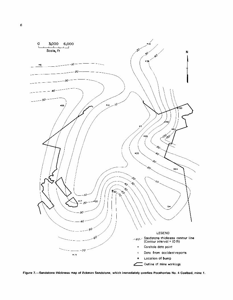
is present through the central portion of the mine area (fig. 7), whereas thicker sandstone accumulations are preserved in the northeast and southwest corners. The variable nature of the thickness of this sandstone unit is most likely the result of the confinement of sand deposi- tion to channels. The mine contains numerous straight, but digitate coal washouts.
These units that overlie the coalbed are structurally competent and, along with the floor shale, enclose the coal- bed with generally unyielding strata. The presence of such well-indurated rock units adjacent to the coalbed is believed to be conducive to the occurrence of coal bumps.
Structural Setting and Overburden Thickness
Mine 1 lies within the Appalachian Plateaus physio- graphic province, which is characterized by gentle, open folds with northeast-southwest trends. The mine is located on the eastern flank of the Mullens syncline, therefore, the elevation of the Pocahontas No. 4 Coalbed decreases from southeast to northwest across the mine area (fig. 8). Faults are absent in this area, however, a large thrust fault, the Boissevain Fault, has been recognized to the south just across the Virginia State line (4). Clastic dikes are also notably absent.
Overburden thicknesses at mine 1 range from approx- imately 400 ft to greater than 1,600 ft. Shallow coalbed depths occur in the southeast portions of the mine where the strata rise toward the crest of the Dry Fork anticline (fig. 9). Thicker sections of overburden are present in the northwestern area of the mine where the coalbed drops in elevation under several topographic highs (fig. 9). with the exce~tion of a limited area in the southeast corner. mine 1 lies beneath more than 500 ft of cover.
Bump Occurrence
On October 18,1983, two miners were killed by a bump accident on a continous miner section, located as marked on figures 7 through 9. No deviations from the general struc- tural trend were evident in the area (fig. 7). Therefore, unusual structural conditions did not lead to the occurrence of the bump. Overburden thickness was in excess of 900 R (fig. 9). Additionally, data from a Mine Safety and Health Administration (MSHA) accident report (5) and in-mine observations indicated that a hard sandstone approximately 60 ft thick was present immediately above the coalbed (fig. 7). The bump occurred during the mining of the 140- by 350-ft No. 3 barrier pillar. Figure 10 illustrates the condi- tions directly after the accident. Eight entries on 39-ft centers were planned to divide the pillar. Forces from the bump moved the continuous miner against the right rib and the shuttle car into the crosscut between entries 5 and 6 (fig. 10). The left rib in the No. 5 entry was displaced approximately 8 ft and coal filled the rest of the entry to a depth of 42 in for a distance of approximately 86 ft. The displaced coal is indicated by a dashed line on figure 10. The roof bolting machine was not moved by the forces; however, coal was expelled, filling the No. 2 entry with coal from 3.5 to 5 ft deep, for a distance of 60 R (5).
According to mine management, the narrow-room ~ e t h o d had been used for several years. However, the
Corehoie data point
0 Data from accident reports
Location of bump
Outline of mine workings
Figure 7.-Sandstone thlckness map of Eckman Sandstone, which immediately overlies Pocahontas No. 4 Coalbed, mine 1.

LEGEND ,,, Structure contour line (Contour interval = 20 ft)
e Location of bump
Figure 8.-Structure contour map for mine 1, drawn from elevation of top of Pocahontas No. 4 Coalbed.

\ - - LEGEND
burden ,@/herburden tMckness contwr l i ~ 500 to 1,000 f i Contour Interval = 100 ft Owburden thickness * Location of bump 1m to '$00 ft - outline of mine ~ i n g s Overburden thickmas
a a p t o e m n . .
Flgurs 9.arbrrrdm map lor mine 1.

PLAN VIEW
LEGEND 7111 Forces - Shuttle car - Continuous miner d Bolter
2 Entry
Scale, f t
Figure 10.-Plan view of area of bump accident on October 18, 1983, mine 1.
specific approach to mining was determined on block-by- block evaluation, based on the knowledge of the miners and mine management (5). Two pillars of similar size and shape (directly inby) were mined prior to the fatal bump pillar (fig. 11). The No. 2 barrier pillar was also developed using the narrow-room method. It bumped during an idle shift, expelling several tons of coal and moving the continuous miner. The No. 1 barrier pillar was split into blocks similar in size to the adjacent chain pillars and was retreated without incident.
The change in the projected development of the No. 3 barrier pillar was due to the bump that had occurred in the No. 2 barrier pillar. It was determined by mine manage- ment that the No. 2 entry (fig. 10) should be developed first to create a chain pillar the same size as the inby pillar, which was developed in the 1930's. Entries 8, 7, 6, 5, and 4 were driven in sequence to form a right-to-left stepped pattern of working faces. It was hoped that this plan would allow a gradual release of any stored energy. A cut-by-cut mining plan was formulated and followed by mine manage- ment. The No. 3 barrier pillar had been mined down to a
100- by 100-ft block, located between entries 2 and 6, sur- rounded by smaller pillars (fig. 10) when the bump occurred (5).
The No. 3 barrier pillar was located at the intersection of two gob areas; loads were transferred from both the old gob to the east and the new gob directly inby (fig. 11). Also, the 100- by 100-ft block was surrounded by small ~ielding pillars on two sides. Figure 12 presents a theoretical schematic of the load transfer along section A-A' (fig. 10). The smaller pillars, through their convergence, permitted the rigid roof [approximately 60 ft of massive sandstone (511 to transfer the load onto the pillar between entries 2 and 5 (fig. 10). The pressure bump manifested itself when the lateral forces exerted by the pressurized pillar core over- came the confining pressure of the crushed periphery. At that point the pillar expanded laterally in an explosive failure.
It should be noted that the pillar geometry of this sec- tion was set many years prior to retreat mining. The con- dition of this area (roof falls especially) often caused changes to be made to the mining plan.
Shortly after the fatal accident, encapsulated hydraulic load cells (6) were installed in four chain pillars on the sec- tion of the fatality. Figure 13 shows the location of the instrumented pillars in relation to the fatality and the place- ment of the hydraulic load cells in pillars A, B, C, and D. The configuration represents the extent of development at the time of instrument installation.
The progress of mining in relation to changes in ver- tical load measured by the hydraulic load cells and the advance retreat mining method are illustrated by figures 14 and 15. The six maps (fig. 14) represent the progress of mining over the 20-week period of instrument readings. The graphs contained in figure 15 display weekly averages of the load cell pressure readings plotted against a time scale in weeks. A scale is included on each graph relating it to the mining period maps.
During mining period 1, the general pattern of the advance retreat method is demonstrated. The area of pillars directly outby the pillar line is split and the second row of pillars outby contain bump cuts. Bump cuts are single cuts taken from the center of solid pillars. This procedure reduces the structural capacity of the pillars in the abutment zone to bear load, allowing the pillars to crush gradually. With the lateral expansion of the pillars adjacent to the pillar line, load is transferred to the outby pillars. This is demonstrated by cell 2 in pillar A (fig. 15A). An increase in load occurred with the splitting of the pillars directly inby, even though the pillar line is approximately 350 ft inby. Cell 2 malfunctioned at the end of week 3; cell 3 was installed nearby directly afterward. Note, the load cells indicate differential pressure only, in that they measure the increase in load because of mining.
While the cells were not placed uniformly with respect to the pillar geometry, they do demonstrate three trends. Pillars A and D did not load significantly until the nearby inby pillars were split (fig. 15). An increase in cell readings

\ - - - . - -
I I , . No. 3 barrier block I barrier bloc
LEGEND 0 100 200 300
a Gob I I I 1
Scale, f t
Figure I 1 .-Plan view of mining sequence prior to bump accident, mine 1.
did not take place in pillar D until mining period 5 (fig. 14). At that time pillar C was split halfway and bump cuts were made in a pillar adjacent to pillar A. Second, the cells load evenly up to the point of periphery yield and confined core loading. This phenomenon is verified by all cells except for the data from pillar B. Finally, all four pillars demonstrated an increase in core loadings upon periphery yield.
The reduction in pillar load-bearing capacity must be carefully controlled or a squeeze may result. Roof-to-floor convergence of as much as 3 ft has occurred, which forces the taking of the floor. The pillar splitting for stress relief illustrated by figure 14 requires a significant increase in equipment travel distance as opposed to conventional room- and-pillar retreat. Mining must be conducted simul- taneously in locations as much as 400 ft apart. At this mine, the mining sequence is determined on a case-by-case basis.
Direction of
I load transfer
LEGEND 2 Entry
Figure 12.-Idealized diagram of abutment force transfer in area of bump accident, mine 1.

0 600 - Scale, f t
Fatal bump (10-1 8-83)
LEGEND @ Hydraulic coal cell
Scale, ft
Figure 13.-Location of hydraulic load cells, in pillars A: B, C, and D, in relation to area of bump accident, mine 1.

Mining period / Mining period 4
Mining period 2 Mining period 5
Mining period 3 Mining period 6
Scale, f t
LEGEND EZBl Mining prior to period / D Mining during period l!B%B Mining in prior periods
Figure 14.-Progress of mining maps, for mining periods 1 through 6, of hydraulic load cell readings, mine 1.

x ldle time Cell I -1- ldle period 0 Cell 2 -r+ Mining period A Cell 3
0 2 4 6 8 10 12 14 16 18 0 2 4 6 8 10 12 14 16 18 20
TIME, weeks
Figure 15.-Graphical display of hydraulic load cell readings, from pillars A, B, C, and D, for mining periods 1 through 6, mine 1.
MINE 2
Stratigraphic Relationships
Mine 2 operates in the Pocahontas No. 4 Coalbed near Gary, McDowell County, WV. Mine 2 lies immediately to the east of mine 1, and the two are separated by a barrier pillar. Conditions in the two mines are similar. Both are retreat mining old workings consisting of chain pillars and barrier blocks that were developed as long ago as the early 1900's. The Pocahontas No. 4 Coalbed is very soft and friable and crushes easily. The coalbed is about 6 ft thick on the average, and locally may attain thicknesses in excess of 8 ft. The coal occurs in several benches, each separated by a clay binder (fig. 16).
Underlying the coalbed is a firm gray shale. As with the floor shale in mine 1, the bottom often cracks and heaves in areas where stresses are applied. Two distinct roof lithologies lie above the Pocahontas No. 4 Coalbed. One is a variable sequence of laminated shale and coal, and sandy shale, ranging from 0 to 10 ft thick. Above the shale sequence, or immediately above the coalbed where the shale is absent, lies the second distinct roof lithology, the hard, medium-gray Eckman Sandstone (7). The distribution of this sandstone over mine 2 is similar to that over mine 1 in that the sandstone displays variable thicknesses (fig. 17). However, the overall thickness of the overlying sandstone is much greater at mine 2 than a t mine 1. A thinner band Figure 16.-Generalized stra
Medium- to dark- gray sandstone
Laminated shale, coal, and sandy shale
Bright, banded coal
Clay binder
Bright coal
Clay binder
Bright coal
Firm,gray shale floor
tig graphic column for mine 2.

\ \ \ \ LEGEND
Figure 17.-Sandstone thickness map of Eckman Sandstone, which immediately overlies Pocahontas No. 4 Coalbed, mine 2.
of sandstone (<90 ft) occurs in the north-central to east- No. 3 Coalbed varies from 4 to 7 ft thick and is overlain central portion of mine 2. Other areas of the mine property by up to 3 ft of weak shale (2). The coal is fragile and friable contain thicker total sandstone accumulations, some in and breaks apart easily. No bumps have been reported in excess of 170 ft. This sandstone is difficult to break on the mines working the Pocahontas No. 3 Coalbed in the area line of pillar extraction. As at mine 1, numerous straight, of mine 2, and this may be attributed to the buffering ef- digitate coal washouts, many with associated rolls, are fect of the overlying weak shale (2). found throughout mine 2. The hard shale and sandstone units create very stable roof conditions; however, bumps tend to occur where the thick sandstone directly overlies Structural Setting and Overburden Thickness the coalbed. Where any of the various shale lithoiogies are present, bumps are generally not experienced. The structure a t mine 2 is straightforward and
In the area of mine 2, the Pocahontas No. 3 Coalbed, uncomplicated. The Pocahontas No. 4 Coalbed falls in eleva- lying approximately 60 ft below the Pocahontas No. 4 Coal- tion from the axis of the Dry Fork anticline, which lies to bed, also occurs in minable thicknesses. The Pocahontas the southeast, and dips gently to the northwest (fig. 18).

Figure 18.-Structure contour map for mine 2, drawn from elevation of top of Pocahontas No. 4 Coalbed.
Major faults are absent; however, a few minor faults have been recognized by mine personnel. No clastic dikes have been observed. Numerous kettlebottoms, which are sometimes concealed, have been noted in roof rock of both the Pocahontas No. 4 and No. 3 Coalbeds.
Overburden thicknesses a t mine 2 are less extreme than those a t mine 1. The Pocahontas No. 4 Coalbed crops out along Tug Fork where several portals lead into mine 2 toward the west. Highest overburden thicknesses are attained in the west-central portion of the mine (fig. 19). Two major bumps have been documented from this area;
both occurred in areas with greater than 1,000 ft of cover. Two other bumps were experienced under 700 to 800 ft of strata (fig. 19). Mine personnel indicate that no bumps have been recorded under creekbeds, plausibly as a result of lower overburden thicknesses in such areas. Additionally, mine personnel note that where surface fractures have been recognized just off the crests of mountains on the mine prop- erty, there have been no bumps in the mine below. Mine personnel believe that these fractures may extend to a depth of 200 ft and theorize that they may relieve some of the stresses imposed by greater overburden thicknesses.

Overburden thickness 9' overburden thickness contour l lne 500 to 1,000 ft Contour Interval = 100 ft 1 Owrburden thickness - M i n e of mine worklngs
[pM)n1*500n - - - O u ~ o f P o c a ~ n ~ s N o . 4 C o a l b e d W b n of bump
0 6mo
Scale, ft
FIgure I B.-Overburden map for mlne 2.

Bump Occurrence
The incidence of bumps in mine 2 dates from about 1946. Prior to that time hand-loading technology was employed. By 1950 over 85 pct of the production was from mechanical mining machines. Continuous miners eventually replaced all the conventional and hand-loading stations (2).
It has been speculated whether the manifestation of bumps was brought about by the advent of mechanized mining or the mining of coal a t greater depth. Thirty-two separate bump accidents occurred from June 1945 to April 1951, resulting in 66 injuries and 7 fatalities a t mine 2. Analysis of these events led mining engineers and manage- ment of the mine to a number of conclusions about bumps in the Pocahontas No. 4 Coalbed. Bumps do not occur where the depth of overburden is less than 600 ft or strong massive adjacent strata are not present. Irregularly sized pillars, especially large pillars spaced among yielding pillars, led to an increased probability of bumps. Coal losses in the form of pillar remnants in the gob increase abutment pressures outby the pillar line. Abutment pressures move outby a t approximately the same rate as the retreating pillar line. Finally, they found that a coal pillar with a length or width
dimension of 45 ft or less will yield and not bump, and generally a coal pillar with a minimum dimension of 160 ft is too large to bump.
The thin-pillar mining system, designed in the 1950's to combat bumps during the mining of barrier blocks, is still in use today. Figure 20 is a schematic of the thin-pillar mining system; the five entries labeled A, B, C, D, and E are developed in advance. The entries are driven on centers of 65 to 75 ft with breakthroughs every 90 ft. Further refine- ment of the system revealed that 65-ft centers produced op- timum balance between pillar softening and squeeze prevention.
The important feature of the thin-pillar method is that it incorporates a bare minimum of barrier splitting outby the pillar line. Barrier splitting is limited to the active gob edge of the barrier pillar. The rigid portion of the barrier pillar is carrying the main roof load, and its gob sides become crushed and softened. All barrier splitting is con- fined to the yielded portion of the barrier pillar, and mining in the highly stressed core is avoided. When the outby end of the barrier is approached, the critical size of the pillar, generally considered to be 160 by 160 ft, is formed. This bump block is left to avoid a potential bump.
/Old gob
Solid coal
Figure 20.-Thin-pillar mining method diagram, mine 2.

Stress relief drilling experiments were conducted in mine 2 to determine if auger holes (2441-1 diameter) could be mined safely. Figure 21A displays a 180- by 170-ft bump block that was formed by the removal of a barrier pillar. The coalbed is 7 ft 4 in thick and the depth of cover is 1,100 ft. The bump block was destressed by auger drilling. Holes A, B, and C were drilled to their predetermined depth of 95 ft from behind barricades (fig. 21B). Upon completion of hole C, three entries following the auger holes were advanced 75 ft and connected by a crosscut. As the crosscuts were being driven, the last 35 ft of the holes closed. Prepara-
tions were made to drill holes D, E, and F, which were con- tinuations of holes A, B, and C. Hole D (fig. 21Q was at a depth of 149 ft in the crushed coal area of what was formerly hole A, when a very heavy bump occurred. Approximately 1,000 st of coal was thrown into the entry. An area 100 by 35 ft was opened over the coal pillar by a gap of 8 to 12 in. Because of the extreme precautions taken, no serious injuries resulted. Drilling resumed and another bump was encountered in hole F, which totally destressed the block. The bump block was then retreated without fur- ther incident.
Solid coal
B . . . . . . .,: . .:>: . . . . . . . . . . .
. . . . . . . . . ,,:..;,.',;;':. t.':..'...... :. .;;.:::..;:-::ii':.. .... ... : a ' , . .,., ., . . . . . - :, >,'.',, :.'..- .,'Old gob t,::,, :.... :::::i..";; ... .......... ..: ............ .* .. 1 . r
Figure-21 .-Results of auger drilling of bump block left by thin-pillar mining method, mine 2.

While the preceding example demonstrates that a bump block produced by the thin-pillar method can be destressed, auger drilling was discontinued shortly afterwards because it was considered by the operator to be uneconomical and dangerous. The thin-pillar method is still employed but the bump block is now left. These holding blocks, a s they are called by mine personnel, serve to provide a rigid member that enhances the probability of breaking the main roof a t the pillar line and to protect the remainder of the section from squeeze development.
A variation of the thin-pillar method is used to retreat old mains that are located between two gobs (fig. 22). A sec- tion 600 ft wide was rehabilitated for a distance of 6,000 ft. Entries labeled 1 and 2 were driven on the rehabilitation- advance phase, while entries 3 and 4 were widened, cleaned, and resupported with roof bolts. The section forms a finger between two expansive gob areas, both of which have been inactive since the 1920's.
Several features of this work merit discussion. First, rehabilitation would have been more productive and prof- itable if entries 3 and 4 were not rehabilitated and new en- tries had been developed in the barrier pillar. However, mine management felt that the possibility for a squeeze would be too great if the center barrier pillar were developed completely on advance. Second, the barrier pillar is split no less than 300 ft outby the pillar line; and no mining is permitted toward the new gob, as pressure could be trapped in the pillar and not transferred outby. Third, when the thin-pillar mining outlines a bump block, it is evaluated by the mining engineering staff on site. If the bump block, such as the one displayed in figure 22, is deemed to be under hazardous loading, it is left as a holding block.
MINE 3
Stratigraphic Relationships
Mine 3 operates in the Pocahontas No. 3 Coalbed near Keen Mountain, Buchanan County, VA. The Pocahontas No. 3 Coalbed ranges from 3 to 6 ft thick, but runs approx- imately 4-112 ft thick a t mine 3 (8). The Pocahontas No. 3 Coalbed is similar to the Pocahontas No. 4 Coalbed in that both are bright, banded, and fairly blocky. At mine 3, a prominent, persistent shale binder is present approximately 18 in from the top of the coalbed (fig. 23). This binder averages about 3 in thick. Because the coalbed is buried deeply, it is generally very gassy, averaging approximately 600 to 700 ft3/st (9). However, the coal is relatively im- permeable, and gas pressures as high as 600 psig have been recorded by mine personnel in drill holes into the coalbed. Results of Bureau research have confirmed these high gas pressures (1 0).
The coal is underlain by a gray fissile shale of variable hardness. In certain areas it is very hard; in others it is quite soft and the upper 1 to 3 ft are sometimes removed to alleviate floor heave. Generally, the roof consists of a shale sequence that may be as much as 150 ft thick or may be absent. Overlying the shale, or lying directly upon the coal- bed where the shale is absent, is the conglomeratic, light- gray to white Upper Pocahontas Sandstone. This sandstone is very hard and causes problems because it does not break easily. Because of management's concern over problems with the breaking of the sandstone and possible ignition hazards due to spark generation, no coal is mined where the sandstone lies less than 24 R above the coalbed. Several
~ n n n - r -
Figure 22.-Thin-pillar mining method as used to retreat old mains located between two gobs, mine 2.

sinuous washouts with associated rolls in the mine are at- tributed to channeling processes prior to the deposition of sandstone. The paucity of corehole information precluded the construction of a sandstone isolith map of the mine property.
Structural Setting and Overburden Thickness
The axis of a syncline, trending northeast-southwest, lies just east of the center of mine 3 (fig. 24). The Pocahon- tas No. 3 Coalbed dips gently toward the axis of this basin, more steeply on the eastern flank than on the west.
A thrust fault has been recognized in mine 3 and may be related to a similar fault in an adjacent mine (fig. 24). This fault strikes N 20" W and has 13 ft of displacement. No crushing of rocks in the proximity of the fault was visi- ble; however, upon development of the entry that en- countered the fault, some fault gouge was observed. No clastic dikes have been recorded; however, kettlebottoms are fairly common.
Overburden thicknesses a t mine 3 are extreme; this mine is the deepest of the five examined in this study. Depth of cover ranges from just under 1,200 ft to in excess of 2,400 ft (fig. 25). Bumps have been noted to occur at various depths throughout the mine, but, according to mine personnel, the majority of bumps are experienced under greater than 2,200 ft of overburden. The locations of several previous bump occurrences are indicated on figure 25. All but one of these bumps took place under more than 2,200 ft of cover.
1-1 Shale roof
Bright, banded coal
Shale binder
Bright, banded, fairly blocky coal
Friable coal with sulfur staining
I-) Fissile,gray shale floor
Figure 23.-Generalized stratigraphic column for mine 3.
LEGEND ,40, Structure contour line
(Contour interval = I0 f t ) = Fault
Location of bump 7 Outline of mine workings
0 3,000 6,000 - Scale, f t
Figure 24.-Structure contour map for mine 3, drawn from elevation of top of Pocahontas No. 3 Coalbed.

n- 17 LEGEND
I Overburden thickness ,1ro0/ Overburden thickness contour line 1,000 to 1,500 f t Contour interval = I00 f t
Overburden thickness @ Location of bump lao0 to 2m ft - Outline of mine workings Overburden thickness 2,000 to 2 9 0 0 f t 0 3,000 6000
Scale, ft
Figure 25.-Overburden map for mine 3.

Bump Occurrence
Longwall Mining
Mine 3 has experienced bumps on longwall as well as room-and-pillar retreat workings. Figure 26 (8) displays the location of six retreating longwall bump events that occurred from March 1972 to May 1974. Mountain bump occurrences were minimized in the tail entry gate road pillars by the implementation of a novel design. Originally, the gate roads were designed in such a way that a large block cut on 100- by 100-ft centers was directly adjacent to the longwall panel on the tailgate side (fig. 27).
Where strata underlying the Pocahontas No. 3 Coalbed in mine 3 are generally soft, the bottom heaves readily. However, in the area of the bump outlined in figure 27, the bottom was composed of a competent sandy shale, which was generally resistant to heaving. The combination of the load transferred to the tailgate from the adjacent gob area (formed by the previously removed panel), the abutment pressure in advance of the longwall plow face, and the unyielding bottom strata, in the operator's opinion, caused the bump. The 100- by 100-ft block was too large to yield under load. Thus, the pillar stored energy until explosive failure occurred.
Two steps were taken by mine management to prevent further bump hazards: (1) the softening, via shot firing of the large tail entry pillar, and (2) a redesign of the gate roads for subsequent panels. Where firm, unyielding roof and floor strata are present with over 2,200 ft of overburden
71 \ 6 / '5 4 - LEGEND
7 Longwall ponel 0 5 0 0 lPOO @ Bump -
Scale. ft 1 Outline of longwall panels q Overburden thickness contour line
%,(Contour interval = 2 0 0 f t )
on the tail entry side of panels employing the old projec- tion (fig. 271, the large pillar is softened. This softening is accomplished by way of volley firing. The ribs of the 100- by 100-ft pillar are drilled and shot (fig. 28). After soften- ing, the pillar stored less than the necessary energy for bumping.
// Gob
T 5 ~ ~ ~ ~ ~ ~ e ~ ~ ! G ~ ~ ~ ~
i- t
- 8 LEGEND 2 / P / d 3 Bump g / m , -Direction of
advance a w 0 100 200 -
Scale, f t
.
L
Solid coal
Figure 27.-Plan view of longwall gate road entries and loca- tion of bump event, mine 3.
Figure 26.-Locations of retreating longwall bump events and overburden thicknesses, mine 3.
Figure 28.-Plan view of shot-fire softening technique, used on tail entry longwall gate roads for bump control, mine 3.

The modified gate road design is diagramed in figure 29. Two 32- by 82-ft yield pillars are located on either side of an 82-ft square pillar. No shot fire softening of the nar- row pillars adjacent to the tail workings is necessary because they fracture and yield upon approach of the longwall face under abutment-zone loading. The large pillar, necessary for roof support considerations, is isolated from miners a id equipment by the yield pillar. '~hus, should the large pillar become overstressed and bump, the working area is shielded. Over 3.3 million st of coal has been mined a t mine 3 and adjacent mines operated by the same com- pany, without an injury during a bump occurrence under the modified gate road design.
Room-and-Pillar Mining
Mine 3 is the only mine operated by this company where room-and-pillar retreat mining has been attempted in the Pocahontas No. 3 Coalbed. Mine 3 and the adjacent mines all have large amounts of coal reserves remaining in the pillars forming the main access entries to their longwall sections. Once the longwall panels have been removed, an attempt will be made to mine the coal left in these pillars.
Numerous bumps have occurred during room-and-pillar retreat mining at mine 3. Pillar splitting for stress relief, similar to the method employed at mine 1, has been at- tempted at mine 3. An experiment to determine the effect of the pillar splitting was implemented in three stages. At first, one row of pillars was split outby the pillar line, resulting in a bump. Then two rows of pillars were split outby the pillar line, resulting in more bumps. Finally, three rows of pillars outby the pillar line were split, resulting in a squeeze that made access to the pillar line
H e a d Tail
Figure 29.-Plan view of modified bump control gate road design, mine 3.
impossible. The experiment ended in the abandonment of an area of pillars 900 by 1,300 ft. Pillar splitting for stress relief was abandoned, and an area 1,000 by 600 ft was ful- ly extracted by a conventional room-and-pillar retreat plan without a bump. According to mine personnel and manage- ment, a solid (unsplit) pillar line is capable of breaking the shale roof. Thus, in an attempt to gradually transfer the stresses from the pillar line outby, a cantilever beam loading situation was formed.
As stated earlier, the gradual yielding of pillars near the pillar line is necessary to avoid the energy storage in the pillar core, which leads to pressure bumps. Without a better measurement method, it is assumed that roof-to-floor convergence may indicate the extent of pillar yield. Figure 30 displays the convergence contours outby the pillar line. Note the 2- to 3-in total convergence along the line from pillar A to B and the 0.5- to 1.5-in total at pillar C. Pillar C was later water infused to enhance pillar yielding.
LEGEND 0 100 200 - 2.5 -Convergence contour - (Contour interval = 0.5 in) Scale, f t
Figure 30.-Convergence contour map for room-and-pillar retreat mining, mine 3.
Water infusion
0 10 20 30 40 50
TIME, d a y s Figure 31.-Graph of convergence effects of water infusion
of pillar C (fig. 30), mine 3.

The water infusion of pillar C was accomplished by pumping water at 800- to 1,200-psi pressure, into the pillar a t a rate of 10 gallmin. Figure 31 shows the effect on the convergence rate around the infused pillar. The dramatic increase in the convergence rate caused by the water infu- sion led mine officials to assume that the pillar was destressed. It was then mined without incident. The same test was performed on other pillars. The increases in con- vergence rate were not as pronounced, but the pillars were mined without incident. Water infusion is not presently con- ducted for bump control a t mine 3.
MINE 4
Stratigraphic Relationships
Mine 4 is actively working in the Chilton Coalbed of the Kanawha Formation (Pottsville Group, Pennsylvanian System) near Stirrat, Logan County, WV. The brightly banded coalbed displays irregular thickness, but averages about 4 ft thick at mine 4. The Chilton is generally multiple- bedded, with intervening partings of shaly coal and bone (fig. 32).
The coalbed is underlain by a fairly soft, medium- to dark-gray claystone. Above the coalbed is a light-gray, cross- bedded sandstone (4). In the areas of mine development, the sandstone lies directly upon the coalbed. However, corehole logs indicate the presence of an intervening gray shale layer approximately 2 ft thick in an area north of mine 4. The sandstone is poorly cemented and brittle and usually breaks a t the pillar line. The thickness of the overlying sandstone is fairly uniform. Except for one corehole data point in the northeasternmost portion of the studied area, the sandstone is generally 40 to 60 ft thick (fig. 33).
Structural Setting and Overburden Thickness
Mine 4, located in the Appalachian Plateaus physiographic province, is situated in a relatively un- complicated structural setting. Structural contour lines, drawn on the top of the Chilton Coalbed, trend northeast- southwest (fig. 34). The mine lies on the east flank of the Handlev svncline: therefore. the coalbed d r o ~ s in elevation
In comparison with other mines examined in this study, overburden depths at mine 4 are relatively shallow (fig. 35). The mine is outlined, for the most part, by the outcrop of the Chilton Coalbed. Only under the hilltops does the over- burden thickness increase to over 700 ft. A fatal bump oc- curred in one of these areas of maximum overburden thickness (fig. 35).
Bright coal
Bone
Bright coal
Shaly coal
Bright coal
Claystone floor toward the northhest. No faults or clastic d i e s have been observed in the area of mine 4. Figure 32.-Generalized stratigraphic column for mine 4.

LEGEND ,40' Sandstone thickness contour line
(Contour interval = 10 f t )
Corehole data point
@ Location of bump
---- Outcrop of Chilton Coalbed
3 Outline of mine workings
1 I I 1 Scale, f t
Figure 33.-Sandstone thickness map of Lower Winifrede Sandstone, which immediately overlies Chilton Coalbed, mine 4.

LEGEND ,1400- Structure contour line
(Contour interval = I0 f t)
@ Location of bump Scale, f t ---- Outcrop of Chilton Coalbed
d , , Outline of mine workings
Figure 34.-Structure contour map for mine 4, drawn from elevation of top of Chilton Coalbed.
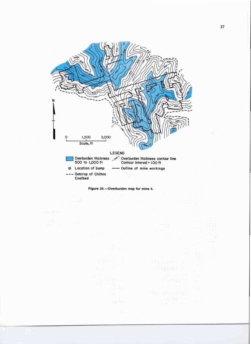
Rgm 35.-OwfW&n rmp lor mhm 4.

Bump Occurrence
Continuous miners are exclusively employed in mine 4. Mining is conducted on the room-and-pillar system. When retreat mining is performed, pillars are removed by the pocket-and-wing method. Figure 36 displays the pocket-and- wing method in the twin-mining format. The sandstone roof directly above the coalbed permits twin mining, because it is uniform and stable. Cuts are made in the numbered se- quence shown. Each pillar is split, then the outside wings are removed. Finally, the inside wings are mined in tandem. The twin-mining procedure produces a high coal yield and total extraction.
On November 29, 1983, a bump occurred, killing one miner and severely injuring another (1 1 ). Retreat mining was underway using the twin-mining method. The depth of cover over this area was 752 ft, which approaches the maximum overburden encountered in mine 4. A map of the bump area is contained in figure 37. Pillars numbered 4 and 5 bumped with sufficient force to move a 26.5-st con- tinuous mining machine 15 ft. The machine was cutting LEGEND 0 50 I I 00
the face of pillar 5 when the accident occurred. Mine officials 14 Sequence of mining J Scale. f t
indicated that a similar bump took place 3 weeks prior to the fatality, during the mining of the pillars inby pillars Figure 36.-Pocket-and-wing method mining sequence, mine 4. 4 and 5.
I::
LEGEND lml Bump location
Gob areas I t ' I Outline of unsurveyed '' ''I mine workings
Outline of surveyed mine workings
I I I
Scale, f t
Figure 37.-Overview of bump accident area, mine 4.
- .- -

I\ Mined out *
I to 2ft thick I to 2 ft thick
Pillars removed / ' . - - - - - , A
No roof falls n LEGEND 0 40 80 I I - Indicates locations of pillars that bumped Scale, ft
* Estimates of roof rock conditions after bump occurrence made by company and Federal investigators
2 Pillar
Figure 38.-Plan view of immediate area of bump accident, mine 4.
A closer view of the accident area is mapped in figure 38. Note the standing gob directly inby and to the left of pillar 4, where the pin machine or roof bolter was located. The fall of immediate roof only in the gob area of pillars 1 and 2 also is significant. The combination of the stress transferred from the yield pillars directly adjacent to pillar 5 (fig. 37) by the rigid roof and the standing gob led to the bump event. Five rows of pillars were then left as a barrier (fig. 37), full extraction was discontinued, and a partial ex- traction procedure was instituted. This pillar splitting reduced the total extraction ratio to less than 60 pct.
MINE 5
Stratigraphic Relationships
Mine 5 operates in the No. 2 Gas Coalbed of the Kanawha Formation (Pottsville Group, Pennsylvanian System) near Milburn, WV. The mine straddles the boun- dary between Fayette and Raleigh Counties. The name "No. 2 Gas" has been applied to the lower bench of the Camp- bell Creek Coalbed, which is split along the Kanawha River
southeastward of Campbell Creek, Kanawha County (12). Throughout the mine, the No. 2 Gas Coalbed is 43 to 63 in thick. The coalbed is friable and displays multiple benches, each separated by binders of bone or shale (fig. 39). A persistent bone binder, noted at several locations in the mine, occurs approximately 1 ft from the top of the coal- bed. A thicker, more prominent and continuous bone layer is also found approximately 1 ft above the bottom of the coalbed. Mine personnel believe that this binder stores energy from overburden pressure. Therefore, they recom- mend the removal of the lower parting first when mining commences.
The floor consists of a medium-gray shale of variable thickness that is underlain by a sandstone approximately 30 ft thick. Five coalbeds are known to exist below the No. 2 Gas, two of which are mined in this area. Above the No. 2 Gas Coalbed is a brown sandstone that displays variable characteristics, with a reduction in structural competence occurring where laminations are present (12). In general, the sandstone lends itself well to room-and-pillar retreat mining. In fact no unexpected roof falls have been reported in the mine. In places, the sandstone is separated from the coalbed by a thin layer of dark shale that tends to peel off

Brown sandstone
Dark shale
Bright coal
Bone
Bright coal
Shale binder
Bright, banded coal
Bone
Bright, banded coal
Medium-gray shale floor
Figure 39.-Generalized stratigraphic column for mine 5.
along the bottom bedding plane of the sandstone and fall. Fifteen coalbeds occur in strata overlying the coalbed, but none of these is mined in the area. The hard, competent strata enclosing the No. 2 Gas Coalbed tend to converge a t points and produce some bottom heaving. The few washouts present most likely resulted from paleochannel activity prior to deposition of the overlying brown sandstone.
Drill-hole information was not available for the con- struction of a sandstone isolith map of the mine area. Therefore, no assessment of sandstone geometry was possi- ble. However, as mentioned previously, the sandstone displays variable features and these are coupled with changes in coal character and sulfur content. Mine person- nel attribute these variations to fluctuating environmen- tal conditions during the deposition of the coalbed and overlying strata.
Structural Setting and Overburden Thickness
Mine 5 lies in the Appalachian Plateaus physiographic province and is situated approximately 15 miles southeast
of the axis of the Handley syncline. The No. 2 Gas Coalbed dips at 1 " to 1.5' to the northwest toward the axis of this syncline (fig. 40). No faults or clastic dikes have been observed in the mine. A few kettlebottoms are present where the shale intervenes between the coalbed and the overlying sandstone.
Overburden intervals a t mine 5 are relatively thin when compared with overburdens of the other mines examined in this study. A large portion of the mine is outlined by the outcrop of the No. 2 Gas Coalbed. As a t mine 4, the thickest overburden is present under hilltops on the mine property. In those areas, the coalbed may be much as 850 ft deep (fig. 41). Large surface cracks have been observed above the coalbed on these mountains. The bump that occurred in this mine on February 10,1984, was located in the deepest por- tion of the mine, under more than 800 ft of cover (fig. 41).
Bump Occurrence
Sandstone units were present directly subjacent and superjacent to the coalbed in the area of the lost-time-injury bump of February 10, 1984. The Powellton and Eagle Coalbeds were extracted by room-and-pillar retreat methods, 98 and 200 ft, respectively, below the site. It is unknown if multiple seam mining effects contributed to the observed bump phenomenon.
Pillar extraction was underway using the pocket-and- wing twin-mining method. This method is very similar to the procedure employed at mine 4. Figure 42 displays the sequence of mining prior to the bump. Note that the min- ing sequence is presented in an idealized manner, as the numbered areas are too large to be removed in one lift. Approximately 300 st of coal was displaced by the bump; the location of the dislodged coal is diagramed on figure 42. One miner was slightly injured by the dislodged coal (13).
It is theorized that the bump was caused by the extrac- tion of pillars located on a pillar point. A pillar point, as defined by previous researchers (I), is a pillar located at the intersection of at least two gob areas. In this case, the pillars were located between three gob areas (fig. 42). Abutment pressure was transferred from three gobs onto the section. This pressure, combined with unstable roof conditions created by the failure of pillar remnants inby the section, caused the bump.
This event was unique among those studied, for three reasons: (1) The center of the bump was not the pillar containing the working face, (2) a 6- to 12-in separation was formed between the roof and the top of the affected pillars, and (3) roof support timbers were broken into a V-shape, but were loosely held between the roof and bottom. These results seem to indicate that the roof transmitted a hammerlike blow to pillars A, B, and C (fig. 42). This type of failure was defined by previous researchers as a shock bump (1).

LEGEND ,2140- Structure contour line
(Contour interval= 10 f t )
@ Location of bump
---- Outcrop of No. 2 Gas Coalbed
2 ' Outline of mine workings
I I 1
Scale, f t
Figure 40.-Structure contour map for mine 5, drawn from elevation of top of No. 2 Gas Coalbed.

Owrburdan thickness ,d Overburden thtcknerr contour llne 500 to 1,WO ft Contour Interval 100 ft
8 Location of bump - Outline of mine worklngs
--- Outcrop of No, 2 Gaa Coalbed -
Scale, ft
agum 41.--Overkrrden map for mlne 5.

KdJ 'UA 7 1 . 2 :/A YLJ Y/,J ?A V'j vA r(' ( r - -
zi
L
LEGEND
and pil- /
pW Indicates bump location
\UDnC)a 18 Miningsequence
Q (-J a a Bump pillar
N 0 100 200 300 I I I J
~ D a a o a o o ~ Scale, ft
Figure 42.-Plan view of area of bump accident, mine 5.

CONCLUSIONS AND RECOMMENDATIONS
In reviewing the five case studies, it is clear that coal mine bumps can occur during retreat mining operations under a variety of geological settings. However, all of the incidents reported have some similar aspects. These include a thickness of overburden greater than 500 ft and struc- turally competent adjacent strata. By evaluating these con- ditions and considering present knowledge of roof control, several recommendations to avoid bumps become apparent:
In pillaring operations, as much coal as possible should be recovered. Leaving pillar remnants or whole pillars in the gob should be avoided. Pillar line points should be avoided insofar as possible. While all points cannot be eliminated, the number can be reduced by careful planning. Long entries protected by barrier pillars 200 to 500 ft wide on each side should be avoided (1 ). Roof spans projecting over the gob should be kept as short a s possible. Barrier splitting should not be done in pillar line abut- ment areas. Blocking out pillars should be planned so that such work is not less than three or four pillars ahead
of the pillar line. In any event, development places should not be advanced toward the pillar line in an abutment zone because of the probability of encountering a highly stressed area. Pillars should all be approximately uniform in size and shape, and large enough to support the vertical load dur- ing development, and small enough to yield under abut- ment zone loadings during retreat mining. Consideration should be given to monitoring with pressure cells, measuring roof-to-floor convergence, delineating lithological transitions, and employing geophysical methods to detect impending problems. Bump reduction techniques other than mine design in- clude slotting, drilling, volley firing, and water infusion. Each of these methods is a means of destressing coal, resulting in pillar load transfer, and must be used with great caution. ~ e t r e a t i n ~ longwalls with carefully designed gate roads (an exam~le is contained in the mine 3 case study), should be employed in place of room-and-pillar retreat in deep mines, when feasible.
REFERENCES
1. Holland, C. T., and E. Thomas. Coal-Mine Bumps: Some Aspects of Occurrence, Cause, and Control. BuMines B 535,1954, 37 PP.
2. Hayduk, M. (US. Steel). Private communication, 1985; available upon request from A. A. Campoli, BuMines, Pittsburgh, PA.
3. Goode, C. A., A. Zona, and A. A. Campoli. Controlling Coal Mine Bumps. Coal Min., v. 21, No. 10, 1984, pp. 48-53.
4. Hennen, R. V. Wyoming and McDowell Counties. WV Geol. Surv. County Rep., 1915, 783 pp.
5. Blankenship, C., and A. T. Castanon. Multiple Fatal Bump Accident (Outburst). MSHA (4015 Wilson Boulevard, Arlington, VA 222031, 1983, 17 pp.
6. Miller, T. C., and R. Sporic. Development of a Hydraulic Device for Measuring Relative Pressure Changes in Coal During Mining: A Progress Report. BuMines RI 6571, 1964, 13 pp.
7. Talman, W. G., and J. L. Schroder, Jr. Control of Mountain Bumps in the Pocahontas No. 4 Seam. Min. Eng. (Littleton, CO), Aug. 1958, pp. 877-891; Sept. 1958, pp. 982-1004B.
8. West, M. L., and C. E. McGraw. Report of Fatal Coal-Mine Bump Accident. MSHA (Drawer AA, Richlands, VA 24641), 1974, 12 PP.
9. Diamond, W. P., and J. R. Levine. Direct Method Determina- tion of the Gas Content of Coal: Procedures and Results. BuMines RI 8515, 1981, 36 pp.
10. Kissell, F. N. The Methane Migration and Storage Characteristics of the Pittsburgh, Pocahontas No. 3, and Oklahoma Hartshorne Coalbeds. BuMines RI 7667, 1972, 22 pp.
11. Davis, J. E. Fatal Outburst of Coal Accident. MSHA (P.O. Box 112, Mt. Hope, WV 25880), 1983, 26 pp.
12. Hennen, R. V. Fayette County. WV Geol. Surv. County Rep., . .
1919, 1002 13. Grose. H. S. Nonfatal Fall of Rib Accident (Coal Outburst).
MSHA (p.0: Box 112, Mt. Hope, WV 258801, 1984, 9 pp.