Embed Size (px)
DESCRIPTION
coal
Citation preview
Coal petrology and petrographic analysis
3.1 INTRODUCTION
Close examination of coal in hand specimen generally shows it to be composed of different layers. Under the microscope, these layers in turn are seen to be composed of mixtures of discrete entities, each class of which is distinguished by having different optical characteristics. Coal petrology is the study of the origin, composition and technological behaviour of these different materials, while the systematic quan-tification of their proportions and characteristics under the microscope is sometimes known as ‘coal petrography’.
The different layers or entities occurring in a single coal may possess quite different physical and chemical properties, and hence their relative abundance and manner of admixture is vital in determining the overall characteristics of a coal seam or mined coal product. Coal petrography has been widely applied to the selection and blending of coals for production of metallurgical coke, and is one of the major considerations in research directed towards coal liquefaction operations. The techniques of coal petrology are also used in geological investigations aimed at assessing the potential of rocks and sedimentary basins as sources of petroleum.
3.2 MEGASCOPICALLY RECOGNIZABLE CONSTITUENTS
The petrology of coal may be studied at either a megascopic or a microscopic scale. From a megascopic point of view, coal may
be classified into two broad groups, the banded or ‘humic’ coals and the non-banded (massive) or ‘sapropelic’ coals. The humic coals are visibly stratified, consisting of layers or bands of organic material of varying appearance, with individual layers usually no more than a few centimetres in thickness. Such coals are derived from a heterogeneous mixture of a wide range of plant debris. The sapropelic coals, on the other hand, are homogeneous, tough materials, often displaying a marked conchoidal fracture. They are made up of specific kinds of fine grained organic matter, notably masses of spores or algal material.
3.2.1 Lithotypes in banded bituminous coals
A large part of the terminology used in coal petrology is derived from the work of Stopes (1919) in recogniz

ing four basic ‘ingredients’ of banded bituminous coal that can be distinguished in hand specimens. These constituents, regarded in current usage as ‘lithotypes’, were identified by Stopes, a palaeobotanist, as follows:(a) Vitrain (L. vitrurn, glass)
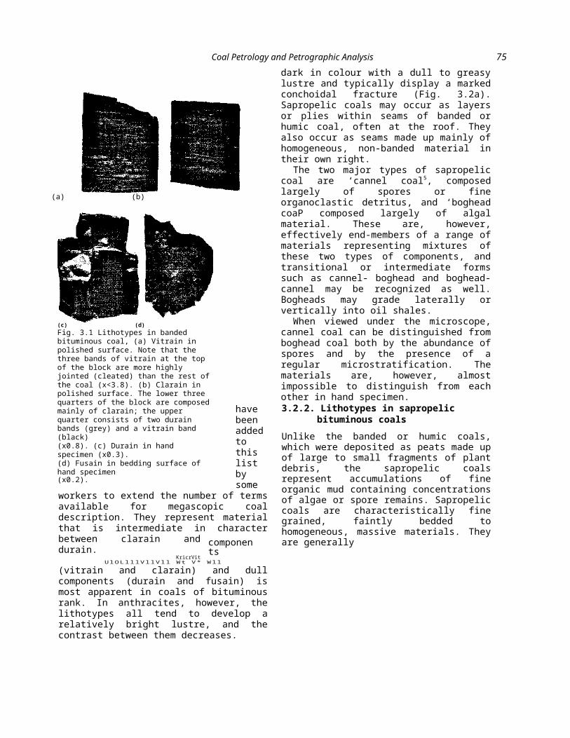
Vitrain is the black, glassy, vitreous material that is probably the most striking component of bituminous coals. It occurs as thin bands, commonly less than 6 or 8 mm in thickness and is usually very closely jointed. Vitrain tends to be more brittle than other megascopic coal constituents, often breaking with a conchoidal fraction (Fig. 3.1a).
(b) Clarain (L. clarus, bright)
This lithotype is represented by bright to semi-bright bands of finely laminated coal. Clarain generally exhibits an overall silky lustre, and commonly contains fine vitrain bands alternating with a duller attrital groundmass (Fig. 3.1b).
(c) Durain (L. durus, hard)
Durain occurs as grey to black bands with a dull to slightly greasy lustre. The material is relatively hard compared to other lithotypes, and tends to break into large, blocky fragments. Durain may sometimes be confused with impure coal or carbonaceous shale, which are also often dull and hard, but it can be distinguished by its lower density (Fig. 3.1c).
(d) Fusain (L. fusus, a spindle)
In French, the word fusain means charcoal, which at one time was made from the wood of the spindle tree. The suffix ^ain’ was adopted for
the other lithotypes. Where it is unmineralized, fusain is a soft, friable material that closely resembles the charcoal from which it takes its name. Soft, or unmineralized, fusain easily disintegrates into a black fibrous powder, but hard fusain, impregnated with mineral matter, may be found in some coals as well. Fusain usually occurs as thin lenses, seldom more than a few millimetres thick, and is only a very minor constituent of most bituminous coal seams on a volumetric basis (Fig. 3.Id).
The terms duroclarain (Cady 1942) and clarodurain
Coal Petrology and Petrographic Analysis 75
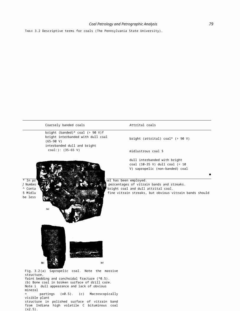
dark in colour with a dull to greasy lustre and typically display a marked conchoidal fracture (Fig. 3.2a). Sapropelic coals may occur as layers or plies within seams of banded or humic coal, often at the roof. They also occur as seams made up mainly of homogeneous, non-banded material in their own right.
The two major types of sapropelic coal are ‘cannel coal5, composed largely of spores or fine organoclastic detritus, and ‘boghead coaP composed largely of algal material. These are, however, effectively end-members of a range of materials representing mixtures of these two types of components, and transitional or intermediate forms such as cannel- boghead and boghead-cannel may be recognized as well. Bogheads may grade laterally or vertically into oil shales.
When viewed under the microscope, cannel coal can be distinguished from boghead coal both by the abundance of spores and by the presence of a regular microstratification. The materials are, however, almost impossible to distinguish from each other in hand
specimen.have
been added to this list by some workers to extend the number of terms available for megascopic coal description. They represent material that is intermediate in character between clarain and durain.
KricrVitU l O L l l l V l l V l l W t V * W l l
(vitrain and clarain) and dull components (durain and fusain) is most apparent in coals of bituminous rank. In anthracites, however, the lithotypes all tend to develop a relatively bright lustre, and the contrast between them decreases.
3.2.2. Lithotypes in sapropelic bituminous coals
Unlike the banded or humic coals, which were deposited as peats made up of large to small fragments of plant debris, the sapropelic coals
represent accumulations of fine organic mud containing concen-trations of algae or spore remains. Sapropelic coals are characteristically fine grained, faintly bedded to homogeneous, massive materials. They are generally
(a) (b)
(c) (d)
Fig. 3.1 Lithotypes in banded bituminous coal, (a) Vitrain in polished surface. Note that the three bands of vitrain at the top of the block are more highly jointed (cleated) than the rest of the coal (x<3.8). (b) Clarain in polished surface. The lower three quarters of the block are composed mainly of clarain; the upper quarter consists of two durain bands (grey) and a vitrain band (black)(x0.8). (c) Durain in hand specimen (x0.3).(d) Fusain in bedding surface of hand specimen(x0.2).
components

76 Chapter 3
3.2.3 Field description of coal seams
Although the terms vitrain, clarain, durain and fusain are widely used for the description of individual specimens or discrete horizons within a coal seam, a number of difficulties arise with their employment in routine logging of seam sections in bore cores or coal exposures (Davis 1978a). One major problem is that these four terms refer to quite different kinds of units within the coal. Vitrain bands represent coalified fragments of wood or bark and are generally no larger than an individual tree trunk in size. Clarain and durain, on the other hand, are usually more extensive units, each possibly representing a aepositional environment within the peat swamp. In a rather exaggerated analogy, the vitrain bands might be compared to an individual pebble, while the clarains and durains are like the conglomerate in which the pebbles occur.
Another disadvantage associated with use of Stopes’ terminology lies in the fact that the individual layers or lenses of the four lithotypes may be very thin, usually only some millimetres in thickness. Even with the accepted minimum layer thicknesses of different countries (3-10 mm), strict application of the Stopes terms can result in extremely detailed descriptions. Many field descriptions of coal seams, however, especially those of very thick seams, are based, for expediency, on sub-division into a relatively small number of megascopically distinct units. The

Coal Petrology and Petrographic Analysis 77
Stopes system was not designed for, and is not particularly effective in, this kind of usage.
Recognizing these and other difficulties inherent in the Stopes terminology of coal lithotypes, Schopf (1960) established a descriptive system for use by the U.S. Geological Survey, and this has been subsequently employed by many others for field use. Schopf s terms are out in Table 3.1. In summary, three constituents are described, namely ‘vitrain’, ‘fusain’ and ‘attrital coal’. The first two are regarded as larger clastic units occurring within a matrix of finely divided attrital coal. The thickness and concentration of the vitrain and fusain are described in terms which are quantitatively precise, and the attrital coal is described as having one of five levels of lustre, ranging from bright to dull.
Another alternative has been to describe the coal with reference only to its relative brightness. Employing terms used in the German coal industry, Diessel (1965) has described coal seams as being composed of megascopically distinct layers of the following types of materials:
(a) bright coal; ^(b) banded bright coal; ^(c) banded coal;(d) banded dull coal;(e) dull coal.There are many similar descriptive
systems in use around the world, and all can be used on as broad or as narrow a scale as necessary or convenient for the particular purpose for which the description is being prepared. A seam may be described on a centimetre scale (e.g. for research purposes), or on a metre scale, as desired.
A combination of the bright-dull system and the Schopf system has been devised by the Coal Research Section of The Pennsylvania State University for effective seam descriptions at a megascopic level, and this is summarized in Table 3.2. Fusain bands or lenses thicker than about 5 mm are recorded separately, as are non-coal bands or partings, for which conventional sedimentary rock terms may be used. Another system, used extensively to describe Australian bituminous coals in outcrops, mine exposures and drill cores, is discussed in Section 6.5.6. Discussions of the preparation and use of megascopic coal seam logs in field studies are also given by Schopf (1960) and Dutcher (1978).
3.2.4 Impure coals
Where the coal contains a significant amount of mineral matter, its overall density and ash yield increase significantly. Although the distinction between clean coal and impure coal is generally based on the economic constraints of mining, marketing and use, most materials regarded in the latter category have an ash yield greater than 25%, and sink when placed in a liquid with a relative density of 1.60. However, where the coal has more than about 40-50% ash, it is usually more correctly described in non-coal terms, for example as a carbonaceous shale or
TABLE 3.1 U.S. Geological Survey terms for megascopic description of banded bituminous coal (Schopf 1960).
VitrainFusain
f brightmoderately bright
Attrital coal J midlustrous
moderately dull1 dull
Thickness classes (mm) Concentration classes (%)thin bands 0.5-2 sparse <15medium bands 2-5 moderate 15-30
thick bands 5-50 abundant 30-60very thick bands >50 dominant >60

78 Chapter 3
a coaly shale.The mineral impurity in the coal
may be in the form of discrete bands, streaks or layers interbedded with the organic constituents, or it may occur as nodules or as fracture infillings. It may be made up of clay or shaley material, or of pyrite, siderite or calcite. Coal with a significant amount of fine clay disseminated throughout the organic matter, rather than in discrete layers, is often described as stony coal or, in the U.S.A., as Tone coal’ (Fig. 3.2b). Such material is characterized by a dull appearance and, commonly, a grey, rather than a black, coloured streak. An indication of the terms that may be used to describe impure coals is given in Table 3.3.
3.2.5 Megascopic features of low-rank coals
For most practical purposes, the distinction between ‘hard’ coals, of bituminous rank or higher, and ‘soft’ or low rank coals is based on the specific energy and other chemical properties of the materials concerned (Section 2.10.2). In European terminology, the low rank materials are generally described as £brown coaf, whereas in the U.S.A. and elsewhere they are classed either as ‘lignite’ or ‘sub-bituminous coal’, depending mainly on their chemical characteristics. Although the term ‘brown coal’ is, strictly speaking, applicable to a wider range of material than ‘lignite’, it is also used as a synonym for ‘lignite’ in many contexts.
Lignite is a dull, soft, earthy material, ranging from
Coal Petrology and Petrographic Analysis 79
TABLE 3.2 Descriptive terms for coals (The Pennsylvania State University).
brown to black in colour. It may occur in a massive sapropelic form or, more commonly, as a humic material with
Coarsely banded coals Attrital coals
bright (banded)* coal (> 90 V)f bright interbanded
with dull coal (65-90 V)
interbanded dull and bright coal:): (35-65 V) bright (attrital) coal* (> 90 V)
midlustrous coal §
dull interbanded with bright coal (10-35 V) dull
coal (< 10 V) sapropelic (non-banded) coalfusain
■
* In practice, only one category of bright coal has been employed.] Numbers in parentheses refer to approximate percentages of vitrain bands and streaks.^ Contains approximately equal proportion of bright coal and dull attrital coal.§ Midlustrous attrital coal may contain many fine vitrain streaks, but obvious vitrain bands should be less than 10%.
Fig. 3.2 (a) Sapropelic coal. Note the massive structure,faint bedding and conchoidal fracture (*0.5).(b) Bone coal in broken surface of drill core. Note i dull appearance and lack of obvious mineral= partings (x0.5). (c) Macroscopically visible plantstructure in polished surface of vitrain band from Indiana high volatile C bituminous coal (x2.5).

80 Chapter 3
Low rank coals, especially lignites, are very difficult to describe by megascopic examination. The colour and lustre may vary with different degrees of dessication, and no generally accepted classification of lithotypes has yet been devised. A classification of brown coal lithotypes is currently being prepared by the International Committee for Coal Petrology (I.C.C.P.), with the different categories distinguished on the basis of colour and texture rather than chemical composition. The terms that have been proposed in this classification are:
(a) xylitic (woody);(b) attritic;(c) fusitic;(d) mineralized.
3.2.6 Applications of megascopic seam descriptions
Detailed megascopic logging of coal seam sections is a time consuming and often difficult task. Conditions of lighting, surface moisture and accessibility may pose problems for the geologist working at a mine face, and even in the somewhat less harried situation of bore core logging, the friability or degree of oxidation of the coal may impede the logging process.

Coal Petrology and Petrographic Analysis 81
TABLE 3.3 Descriptive terms for impure coals.
impure coal, undifferentiated bone coal*impure coal, with shale bands/streaks (alternative name: shaley coal) impure coal, with pyrite layer(s)/band(s)/nodule(s)/etc. impure coal, with carbonate band(s)/nodule(s)/etc.
* ‘Bone coal’ is an American miners’ term for describing coal in
which a significant amount of fine clay is disseminated through
the coal rather than occurring in obvious shale partings. Conse-
quently, bone coal has a dull appearance and a grey streak.
Fresh, clean surfaces are needed for good descriptions and cores should be carefully broken open, while in situ seam exposures should be cleared of any weathered debris or fire retardant stone dust (as used in underground mines) prior to logging.
A geologist inspecting a seam exposed at a mine face or in an exploratory bore core has a unique opportunity to record the exact structural characteristics of that seam before it is destroyed either by mining or by the analysis process. Even though, in some instances, there may be a lack of consistency between results from different workers, experienced personnel are often able to obtain a considerable amount of useful data that may be evaluated in conjunction with other ply-by-ply analyses for very little additional cost.
Some coal seams have characteristic lithotype profiles that remain more or less constant over wide areas, or contain marker beds of distinctive character that can be recognized in many parts of the field. A detailed megascopic log, perhaps expressed in graphic form, may be very useful in correlating the individual seams in a coal-bearing succession, and in the interpretation of displacements in faulted strata. Durains and fusains have proved
especially useful in this regard (Cameron 1971; Austin & Davis 1979) as have individual bands of non-coal material (e.g. Mackowsky 1968a).
Megascopic profiles or logs of the seam are also potential sources of information on variations in coal quality that may affect the mining, preparation or utilization of the material. A brightness log based on the descriptive system of Diessel (1965) has been used, for example, as a rough guide to the coking potential of individual seams in Australia (Hawthorne & Tweedale 1967). Although it is not necessarily proper nor wise to draw inferences on the maceral composition of seams from such data, it has proved possible to make at least some correlation with micropetrographic characteristics in a number of cases (e.g. Diessel 1965; Cameron 1978; Marchioni 1980).3.3 MICROSCOPIC APPEARANCE OF COAL
MACERALS
When viewed under the microscope, coal is seen to consist of particles and bands of different kinds of carbonaceous material. These discrete entities represent the coalified remains of the various plant tissues or plant-derived substances that existed" at the time of peat formation. They are distinguished from each other on the basis of their morphology, hardness and optical properties, and also exhibit differences with respect to their chemical characteristics or technological behaviour in coal utilization.
The different entities that make up a coal in this way are known as ‘macerals’, a term coined by Stopes (1935) as an analogy to the minerals of inorganic rocks. Several of the maceral names suggested by Stopes

82 Chapter 3
were adopted at the 1935 Heerlen Congress, and as a consequence the universally adopted classification of these components is referred to as the Stopes-Heerlen system.
Much of the early work on the micropetrology of coal, including Stopes’ original classification, was carried out using thin sections viewed in transmitted light. However, Stach (1927) pioneered the use of polished sections studied in reflected light, under oil immersion. This development paved the way for more efficient and consistent practice of coal petrography. Although the techniques tend to complement each other to some extent, almost all routine petrological work at present is based on polished section methods. The criteria by which the various macerals are identified depend mainly on their appearance and optical characteristics under reflected light illumination.
All maceral names in the Stopes-Heerlen system have the suffix ending finite’. Two of these macerals are entities which, when observed under the microscope, are seen to make up the bulk of the lithotypes vitrain and fusain, and they have been named vitrinite and fusinite, respectively. The other lithotypes, namely clarain and durain, are generally composed of a heterogeneous mixture of macerals of different kinds.
Coal macerals in the Stopes-Heerlen system are classified into three groups on the basis of their physical appearance, chemical characteristics and biological affinities (Table 3.4). The appearance of the members of each group, however, changes with advance in coal rank, and the distinctions between the groups that are easily seen in low rank bituminous coal may, for example, be lost in semi-
anthracite. In some cases, particularly with brown coals (lignites and sub-bituminous materials), different names may be used for macerals of similar origin to emphasize these characteristics.
Coal Petrology and Petrographic Analysis 83
The appearance of the different macérais in transmitted light is the antithesis of that in reflected light, since a material that is relatively transparent is inherently a poor reflector. Coal for thin section study must be ground to a thickness of about 10/un (Section 3.7.1), one-third that needed for other rocks, and this makes the preparation process a highly skilled and time-consuming operation.
A comprehensive summary of the features that characterize the various members of the macérai groups is given in the International Handbook of Coal Petrography published by the International Commission on Coal Petrology (I.C.C.P.
1963, 1971, 1976). This all-embracing reference gives a complete definition for each macérai, including the derivation of its name and a list of any synonyms, as well as its morphography,
nrnnprfi AC rhprmrol phoro/^tpricti^c or-i rl Ü1WCU VllVllllVUl VliUiaVLCl IOLIVO anu
3.3.1 The vitrinite group
Vitrinite is the preponderant macérai in most coals. It originates mainly from the preservation of the stems, roots and leaves of plants, including the wood, periderm and leaf mesophyll tissues and some cell fillings, all with varying degrees of mechanical degradation but relatively minor oxidative alteration. Vitrinite is also formed from colloidal humic gels. Plant cell structure may often be observable under the microscope (Fig. 3.3a), and sometimes even by the naked eye (Fig. 3.2c) in the larger vitrinite occurrences.
In thin section, vitrinite is moderately transparent and appears coloured in various shades of red, orange and brown. In reflected light under oil immersion, however, it appears medium grey in contrast to the darker liptinite and lighter inertinite macérais (Fig. 3.3b).
Vitrinite occurring in vitrain bands of
about 3-12 mm in thickness represents the mummified and coalified products of larger roots, bark and stems of plants. This type, or sub-maceral of
vitrinite is known as
‘telocollinite’. Where a distinct cell structure is visible the term ‘telinite’ has been used, although some authors prefer to restrict this particular term to the cell wall material only. In some instances it is possible to identify the
actual plant genus from which such vitrinite was derived.
Apart from the relatively thick bands derived from woody components,
other vitrinite originates from
botanic affinities. It also includes theories on the mode of origin of the various macérais, and an indication of their respective significance to commercial processes.
^ telinite V
collinitevitrinite
liptodetrinite
inertinite
84 Chapter 3
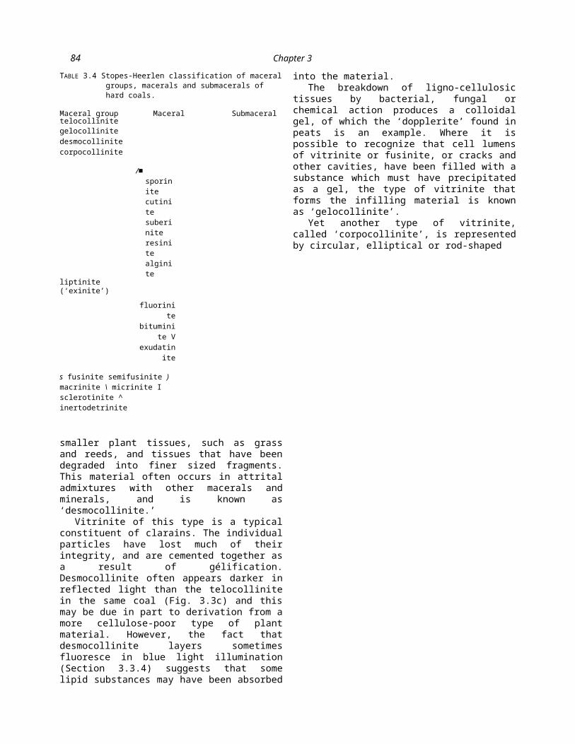
TABLE 3.4 Stopes-Heerlen classification of maceral groups, macerals and submacerals of hard coals.
Maceral group Maceral Submaceral telocollinitegelocollinite
desmocollinite
corpocollinite
/■ sporinite cutinite suberinite resinite alginite
liptinite(‘exinite’)
fluorinite
bituminite V
exudatinite
s fusinite semifusinite ) macrinite \ micrinite I sclerotinite ^ inertodetrinite
smaller plant tissues, such as grass and reeds, and tissues that have been degraded into finer sized fragments. This material often occurs in attrital admixtures with other macerals and minerals, and is known as ‘desmocollinite.’
Vitrinite of this type is a typical constituent of clarains. The individual particles have lost much of their integrity, and are cemented together as a result of gélification. Desmocollinite often appears darker in reflected light than the telocollinite in the same coal (Fig. 3.3c) and this may be due in part to derivation from a more cellulose-poor type of plant material. However, the fact that desmocollinite layers sometimes fluoresce in blue light illumination (Section 3.3.4) suggests that some lipid substances may have been absorbed into the material.
The breakdown of ligno-cellulosic tissues by bacterial, fungal or chemical action produces a colloidal gel, of which the ‘dopplerite’ found in peats is an example. Where it is possible to recognize that cell lumens of vitrinite or fusinite, or cracks and other cavities, have been filled with a substance which must have precipitated as a gel, the type of
vitrinite that forms the infilling material is known as ‘gelocollinite’.
Yet another type of vitrinite, called ‘corpocollinite’, is represented by circular, elliptical or rod-shaped

Coal Petrology and Petrographic Analysis 85
bodies, occurring either in isolation or as cell fillings. This is the high-rank equivalent of ‘corpohuminite’, a maceral of low rank coals described more fully in Section 3.3.5.
3.3.2 The inertinite group
The macerals of the inertinite group are characterized by a high reflectance, and have higher carbon and lower hydrogen contents than other macerals in coals of equivalent rank. They are essentially opaque in thin section, but appear white or light grey in polished section. The inertinite macerals are mainly derived from the same basic types of organic matter as vitrinite, but owe their properties to oxidation of.t _ ____. 1 — 1 — r* «-> QilfllT ctOtTP tViP mill’s
tnose materials ai an wn) t-v ~
formation.
The name inertinite was selected as a group name to imply the relative inertness of these macerals in technological processing (e.g. coke manufacture) in comparison to the members of the other two maceral groups. However, one of these macerals (semifusinite) sometimes displays sufficient reactivity in processes, including carbonization, that the term ‘semi-inert’ has been used by some workers to describe such materials. Microscopic observations made of a heated coal sample by Nandi and Montgomery (1967) also suggest the possibility that another maceral (micrinite) is far less ‘inert’ than had originally been thought, but this conclusion has been disputed by other investigators in the field.
(a) Fusinite and semifusinite
Although, in certain circumstances, plant materials are transformed into vitrinite, in other circumstances identical materials are seen to have undergone a radically different process, giving rise to a brittle, opaque maceral called ‘fusinite’. A plant origin
is recognizable for this material from the well-preserved cell structure, and. fine detail of the cell walls may be commonly seen (Fig. 3.3d). The cell lumens of fusinite may be open cavities or they may be infilled with minerals (carbonates, pyrite, clays) or with gelocollinite. Where a lack of infilling has resulted in the eventual collapse of the brittle cell walls due to compression, a broken ‘bogen’ structure may be developed (Fig. 3.3b).
Fusinite is opaque in thin section and in reflected light is the most highly reflecting
maceral in most ranks of coal. It generally appears white, sometimes even yellowish in polished section studies. Where there is the same detail of preservation of cell
1 Q51 Y ‘serretinn-----------‘scierotioids’

86 Chapter 3
structure, but the level of reflectance is grey and intermediate between that of the vitrinite and fusinite in the same coal, the maceral, which also usually appears brown in thin section, is known as ‘semifusinite’ (Fig. 3.3b and d). For convenience, some petrologists have set an arbitary reflectance threshold of 2.0% to distinguish between fusinite and semifusinite in petrographic analysis. ^
Organic cell fillings which were emplaced early in the coal’s history may also be subject to the fusiniza- tion process. Thus, oval resin bodies (Section 3.3.3) may be converted into masses which, because of their shape, high reflectance and the presence of cavities (Fig. 3.3e), can be easily mistaken for fungal sclerotia (Section 3.3.2e). These bodies may be called fusinite, semifusinite or macrinite (Taylor & Cook 1962), sclerotinite’ (I.C.C.P. 1971) or ‘resino-sclerotinite (Stach 1966; Lyons et al 1982). Several authors, including Kosanke and Harrison (1957) and Lyons et al (1982), believe that many of the resin rodlets from which resino-sclerotinite was derived were probably/if marlnllnCilfl 01*1^171. -
(b) MacriniteAlthough it has a similar level of reflectance to fusinite, macrinite occurs most often as small, rounded but irregularly shaped bodies without cell structure, usually ranging from 10 to 40 /¿m in diameter. Macrinite often appears homogeneous, but it is also apparent that some macrinite has originated through the fusinization of gelified tissues. Certain durains contain relatively large amounts of macrinite in association with sporinite (Fig. 3.4a).
(c) Micrinite
Micrinite is another highly reflecting coal maceral. It occurs as very small, rounded grains, rarely more than a few microns in size (Fig. 3.4b). The grains are in fact discrete particles, but they
tend to form accumulations, either as lenses or layers or in cell lumens. In transmitted light, micrinite is opaque and, in large aggregates it may be difficult to distinguish from fusinite or macrinite.
Micrinite is a ubiquitous component of bituminous coal, particularly in durains and sapropelic coals, but it is rarely present in large quantities. It commonly occurs in association with sporinite and other liptinite group macerals. Micrinite occurs far less commonly in lignites and sub-bituminous coals, a fact which supports the hypothesis that it is generated as a result

Fig. 3.3 Reflected-light photomicrographs of coal (under oil immersion), (a) Vitrinite showing the cell structure of lycopodperiderm (x270). (From Davis et al 1976.) (b) Vitrinite appears medium grey in contrast to the light grey fusinite and semifusinite and the dark grey liptinite macerals sporinite and cutinite (centre). The semifusinite seen at the top of the photomicrograph has a lower reflectance and less distinct cell wall outlines than the fusinite, which displays ‘bogen’ structure.Pyrite, occurring mainly as small euhedral crystals in the centre, appears white (x480). (c) The telocollinite in coarse bands at the top left and bottom right has a higher reflectance than the fine desmocollinite occurring in the central attrital layer with fragments of other minerals (x 480). (d) Fusinite (white) and semifusinite (light grey), both showing well defined plant cell structure (x480). (From Davis et al 1976.) (e) Resino-sclerotinite or sclerotioid in Permian high volatile bituminous coal from southern Africa. Note the deep notch which can be a feature of these bodies (x480). (f) Sclerotinite (white) derived from fungal sclerotia with isolated resinite bodies (dark, oval) in a Late Eocene sub-bituminous coal from Washington (x330).
82 Chapter 3
of the chemical changes that accompany coalification (Stach 1968; Teichmiiller 1974a). However, it can also be observed in cell fillings of very low rank coals, in which case it may represent an end product of the decay of woody tissues.
iHS~
P ■(d) Inertodetrinite
Inertodetrinite is composed of broken fragments of inertinite macerals (Fig. 3.4f, 3.5a and d). According to I.C.C.P. (1971) a fragment of fusinite or semifusinite which has less than one complete cell should be classed as inertodetrinite. However, when a petrographic study is being conducted for the purpose of interpreting the depositional environment of the coal, it may be reasonable to identify as inertodetrinite any small piece of fusinite which has been detached from a larger mass and deposited away from the immediate vicinity of other similar fragments in any attrital coal band. Discrete fragments of fusinite (or semifusinite) which represent less than an entire cell may also be observed in the resin binder of polished section grain mounts. Such particles are, however, better classed as fusinite (or semifusinite) because they are more likely to have been detached from a fusain lens than from an attrital coal lithotype during sample preparation.
(e) Sclerotinite
With the exception of most micrinite, all of the macerals described above have probably been derived, in one way or another, from the ligno-
cellulosic tissues of plants. Sclerotinite is another maceral that is opaque in thin section and highly reflecting, but this material originated instead from fungal remains. The high reflectance in this case is due to the presence of dark pigment (melanin) rather than the main component of such bodies, the polymer chitin (Stach et al 1975).
Material classed as sclerotinite includes all coalified sclerotia, fungal spores, hypae and plectenchyme. True sclerotinite is a ubiquitous component of Tertiary coals, occurring as rounded spores and sclerotia some tens of microns in diameter and having one or more cell cavities (Fig. 3.3f). Bodies which appear similar to sclerotinite may be observed in Carboniferous coals (Fig. 3.3e), but these are usually oxidized or fusinized resin rodlets (Section 3.3.2a). The cavities of these bodies can generally be discerned as vesicles rather than a regular cell structure (Stach et al 1975; Lyons et al 1982).
3.3.3 The liptinite (or exinite) group
Material derived from the outer layer, or exine of spores and pollens was originally referred to by Stopes (1935) as ‘exinite’. However, the meaning of the term was expanded to include coalified cuticular (leaf cuticle) material (Jongmans et al 1935), and eventually macerals derived from algae and resin bodies as well. The term ‘liptinite’ is more appropriate to encompass all of these macerals, together with the more recently identified components suberinite, liptodetrinite, fluorinite, bituminite and exudatinite.
The macerals of the liptinite (or exinite) group appear darker in reflected light than the associated vitrinite, and are generally pale in colour under transmitted illumination. They represent a diverse assemblage of small organic particles, characterized, particularly in

Coal Petrology and Petrographic Analysis 83
low rank coals, by a high hydrogen content and a high proportion of volatile matter. The optical properties and chemical characteristics, however, change significantly as rank advances from high volatile to medium volatile bituminous coal, and many of the distinguishing features are lost in the higher rank materials.
The most common of the liptinite macerals in humic coals are the coalified remains of spore and pollen exines called ‘sporinite’. The typical appearance of these materials is that of a flattened oval shaped particle with a central cavity or line indicating that the inner layer and protoplasm of the structure has decayed (Fig. 3.4a). The size of these particles ranges from about five to several hundred microns, while the shape, including thickness and ornamentation, is extremely varied.
In thin section, the colour of sporinite is yellow or orange in high volatile coals. Like the other low- reflecting macerals described below, sporinite can display a high level of fluorescence under blue or ultraviolet irradiation (Section 3.3.4). Sporinite is abundant in some durains and clarains and is the characteristic constituent of cannel coals.
In coals with a volatile matter yield of less than 29.5% (d.a.f.), a point known as the ‘coalification jump’, the reflectance curve of sporinite (Section 3.6.4) begins to converge with that of vitrinite. The two curves are coincident at a volatile matter of about 21% and a reflectance of about 1.50%, and it is not possible to distinguish between the two macerals under oil immersion in these circumstances. In high rank coals, optical differentiation of these macerals
may be improved to some extent by using methylene iodide immersion techniques.
(b) Cutinite
The waxy cuticular coatings on certain aerial epidermal tissues, notably leaves, are preserved in coal as cutinite. The functions in life of this cutin, an insoluble polymer, are to prevent the delicate tissues from rapid desiccation, and to give them physical support and protection from biochemical agencies. An entire organ with a double layer of cutinite may be preserved as in Fig. 3.4c, where the inner mesophyll of a leaf has been converted into vitrinite. Frequently, however, the resistant cutinite is all that remains of the parent plant structure.
Cutinite usually occurs as very thin elongate bodies. A series of cusps or teeth may be seen on one side of the cuticle to indicate where it originally extended between the radial walls of epidermal cells. Cutinite can also be relatively thick (Fig. 3.4d), indicative in some instances of a dry, sunny climate. Thick cuticles may result from extensive cutinization of the epidermal tissues or the build-up of many layers. Unusually rich accumulations of cutinite occur in rare but well-known occurrences of paper or leaf coals (Auerbach & Trautschold 1860; Guennel & Neavel 1959; Cook & Taylor, 1963).
(c) Suberinite
The corky cells of the plants that contributed to coals, particularly those of the Tertiary, contained the waxy polymer suberin, which is similar in many ways to the cutin of cutinites. Both are mixtures of substances, mainly fatty acids, and are consequently impervious to water. The functions of suberin are similar to those of cuticle,
84 Chapter 3
but suberin is deposited within the cell walls rather than outside them.
In reflected light, suberinite stands out as the dark walls of the relatively large cork cells. These are filled with more highly reflecting materials (Fig. 3.4e).
(d) Resinite
Coalified resins occur in coals as more or less oval or rod-shaped bodies at their original sites of deposition in cell lumens (these are primary resinite). Other material (secondary resinite) clearly has been mobilized at some stage, and occurs as veins or cleat fillings and in pods or cavities such as fusinite cell lumens. Crelling and Dutcher (1980) showed that secondary resinite can have quite different fluorescence properties to either primary resinite orexudatinite (see below) in the same coal. A third and common mode of occurrence for resinite, however, is as bodies which have been weathered out of the other plant tissues and incorporated as transported particles within attrital coal layers (Fig. 3.3f, 3.4f).
The colour in thin section and the reflectance resinite can vary widely, even within a single coal. It can approach that of the vitrinite with which it may be intimately associated, so that microscopic differentiation of the two becomes difficult. Polished sections sometimes show internal reflections, while in transmitted light, resinite may be shades of yellow, orange, red or brown. Oxidized resinite bodies can have rims which are relatively higher in reflectance than the interiors. Resino-sclerotinite is fusinized resin with a high reflectance and is often vacuolated (Section
3.3.2a).Some discrete resin-rich bands are
also encountered in coals. These may be layers of secondary resinite or attrital accumulations of weathered resin bodies. Tertiary and Cretaceous coals contain relatively large amounts of resinite because of the contribution from conifers. The resinite may be concentrated from low rank coals for commerical use either by a special coal preparation process or, because it is more soluble in benzene than other liptinite macerals, by a solvent-extraction technique.
(e) Alginite
Alginite represents the coalified remains of algae. Such material is rare but not unknown in humic coals, and abundant in the variety of sapropelic coal known as boghead coal or torbanite. It is also abundant in some oil shales.
The individual algal colonies are oval in shape, often with scalloped outlines, and these help to differentiate alginite from sporinite in reflected light (Fig. 3.5a). Alginite also has a somewhat lower reflectance than other liptinite macerals. In thin section alginite has a pale straw colour in low rank coals, but is somewhat orange at higher ranks.
Examination in blue or ultraviolet light reveals more of the details of the colonial structure of alginite than can be seen in ordinary white light (Fig. 3.5b). Alginite has a high intensity of greenish-white or yellow fluorescence in low rank materials, but is darker in fluorescence colour at greater levels of organic maturation.
Two of the genera of algae that may be identified in coals (Pila and Reinschia) have been related to the living species Botryococcus braunii. A.C. Cook (personal

Coal Petrology and Petrographic Analysis 85
communication) has suggested that much of the material in cannel coals that has been described

86 Chapter 3
Fig. 3.4 Reflected-light photomicrographs of coal (under oil immersion), (a) Sporinite (dark) and macrinite (light) in durainfrom a Carboniferous high volatile bituminous coal, Kentucky (x480). (b) Micrinite (white) as lenses in vitrinite (grey) and as a thick layer (x480). (From Davis et al 1976.) (c) Thin layers of dark grey cutinite enclose light grey vitrinite derived from leaf mesophyll. Jurassic Maghara seam, Egypt (x205). (d) Thick cutinite in leaf coal from Leping Country, Jiang Xi Province, China (x480). (e) Thin layers of dark suberinite in a Palaeocene sub-bituminous coal from Wyoming.The thick black lines in the bedding plane are desiccation cracks (x480). (f) Lenses of resinite. Note the small vertical cracks joining resinite occurrences; these represent secondary mobilization of resinite or exudatinite (x480).

Coal Petrology and Petrographic Analysis 87
as bituminite (Section 3.3.4) may very well be the material described by Hutton et al (1980) as ‘alginite B\ a lamellar alginite with affinities to the genus Pediastrum.
(f) Liptodetrinite
Liptodetrinite, the member of the liptinite group equivalent to inertodetrinite, is composed of fragments of the liptinite macérais sporinite, cutinite, resinite and alginite (Fig. 3.5a).material has a strong yellow
fluorescence when irradiated with blue light. Fluorinite has a maximum fluorescent intensity at a lower wavelength than other liptinite group macerals at the same level of rank. Consequently, the red/green quotient, that is, the ratio of the relative intensity at 640 nm to the relative intensity at 500 nm, is always lower than those of the other macerals.
Fluorinite is believed to originate from plant oils and fats. It is a ubiquitous maceral of European coals (Teichmtiller, personal communication), but is rarer in the coals of the eastern U.S.A.
3.3.4 The fluorescence of the liptinite macerals
______u___________________«...i ne iipimuc liiaeciaid ui cuai nave me piupcny mdisplaying a fluorescence when viewed under blue light irradiation. Descriptions of the apparatus employed for studies of these autofluorescence characteristics are given by van Gijzel (1971), Ottenjahn et al (1974) and I.C.C.P. (1976). High- pressure mercury or xenon lamps are used for illumination in qualitative fluorescence microscopy, with a blue or ultraviolet excitation filter to remove much of the visible light. A blue filter, for example, with a maximum transmission wavelength of about 400 nm may be used in conjunction with a red suppression filter to achieve the desired results. In some microscopes, the vertical illuminator contains a dichroic beam-splitting mirror which reflects light of below 510 nm. A barrier filter removes the reflected excitation rays and protects the eyes from exposure. For the blue light assemblage just described, a barrier filter with peak transmittance at 530 nm is generally most suitable.
As a result of fluorescence studies, Teichmtiller
t i r \ n A - i _ \ ______i _____________A / - \ C \ H H \ U ______
anu iciLiiiiiunci aim wun \ i y / / ; nave
named a number of materials present in coal which had not been previously identified or distinguished from other coal constituents. The new maceral names proposed include fluorinite,
bituminite and exudatinite. The optical properties of these macerals, summarized in Table 3.5, reveal that these are quite different substances from the better known liptinite macerals, namely sporinite, cutinite, resinite and alginite.
(a) Fluorinite
Because of its black appearance, sometimes with internal reflections, in reflected white light with oil immersion, this pure organic substance could be mistaken for lenses or layers of clay minerals in the coal. However, Teichmtiller (1974) has noted that this(b) Bituminite
Bituminite is the most frequently occurring of the three new liptinite macerals. It is seen as irregularly- shaped shreds, wisps and layers of a material with reflectance intermediate between those of vitrinite and sporinite. Bituminite may even form the groundmass of some durains and sapropelic coals. Previously, it had often been identified as liptodetrinite, the fragmented form of liptinite, but Teichmuller (1974a) notes that bituminite has a fluorescence property that clearly distinguishes it from all other macerals, namely a fluorescence intensity that increases by as much as 200% after a 30 min

88 Chapter 3
period of irradiation. The usual fluorescence colours are orange to brown, and the maximum fluorescence of bituminite occurs at a longer wavelength than does that of other macerals.
Teichmuller has suggested that bituminite represents the decomposition products of algae, bacterial lipids and animal proteins. However, Hutton et al (1980) believe that some of the material that has been called bituminite is really alginite B (Section 3.3.3.e). Teichmuller (1974a) has also suggested that the generation of some micrinite in coals results from
A : _______„ r u : . . ________U 1 C U i a g C l l C M f c U l U l l U l l l l i l l l C .
(c) Exudatinite
The mode of occurrence of exudatinite indicates that it is a secondary maceral which has been soft and mobile at some stage during the coalification process. Exudatinite appears black under reflected light in oil immersion, and it is only by the use of a dry objective or fluorescence illumination that what appeared to be empty cracks and cavities are sometimes seen to be filled with a material that typically has an orange to yellow fluorescence in blue light irradiation.
The cell lumens of fusinite or semifusinite and the chambers of sclerotinite frequently provide the cavities in which exudatinite may occur. Some cracks containing exudatinite may also be joined to primary
Coal Petrology and Petrographic Analysis 89
lipinite macerals such as cutinite and resinite. The reflectance and fluorescence intensity of the exudatinite, however, are respectively higher and lower than those of the primary liptinite occurrences.
Teichmtiller (1974a) has observed that the maximum fluorescence of exudatinite occurs at a significantly different wavelength to that of sporinite, regardless of the rank of the coal. Other distinguishing features of exudatinite are the broad maximum in its fluorescence spectrum, and a tendency to display an initial increase in fluorescence intensity, followed by a decrease as the time of exposure is extended (Table 3.5).(d) Other fluorescent materials
In addition to the presence of the three new macerals, fluorescence microscopy has revealed certain phenomena which Teichmiiller (1974b) has associated with the generation of mobile ‘bitumen’. These include ‘oil exudations’, ‘smear films’ or the darkening of vitrinite as a result of irradiation, and fluorescent vitrinite, presumably due to the incorporation of lipoid substances. The fluorescent vitrinite is usually
that which occurs in attrital bands rather than as bands of telocollinite.
(e) Quantitative fluorescence photometry
In quantitative spectral fluorescence photometry, the recommended optical apparatus is somewhat different to that described above for qualitative work (Ottenjahn et al 1974; I.C.C.P. 1976; van Gijzel 1979). A mercury lamp is used with an ultraviolet filter or
TABLE 3.5 Origin and properties of new liptinite group macerals. (Modified after Teichmtiller 1974a.)
Macérai Form
Appearance in
reflected light (oil)
Intensity Colour
Maximum fluoresence intensity (X)
Red/greenquotient
(Q)
Alteration of fluorescence intensity with
time
fluorinite lensesBlack,occasionalinternalreflections
strong brilliantyellow
510-570 nm ca. 0.5 weak, even negative
bituminite streaks and as
groundmassReflectance intermediate between vitrinite & sporinite
weak orange to brown ca. 635 nm ca. 2.6 very strongly
positive -
exudatinitecavityfillings
black variablemostly yellow to
orange and red-
brown
ca. 635 &580 nm
ca. 2.2often an in-
crease then
decrease

90 Chapter 3
filters to produce excitation mainly by the mercury band at 365.5 nm, since a full fluorescence spectrum cannot be obtained with the blue light filter combination. Spectral analysis of the fluorescence emitted by the object in the range 400-700 nm is made by a motor-driven continuous interference filter or grating monochrometer synchronized with a chart recorder. The barrier filter is withdrawn in this case while the measurements are taken. The photomultiplier used should also have an adequate response through the relevant spectral range.
It is the shape of the fluorescence spectra that is currently used in coalification studies, not the absolute intensities involved. The parameters measured include the peak wavelength, the red/green quotient, and the ‘alteration’, which is an increase or decrease (fading) in intensity after specified periods of irradiation. Ottenjahn et al (1974) have shown that the peak wavelength and the red/green quotient obtained on sporinite increase with increasing rank up to medium volatile bituminous coal, which is the highest rank in which the fluorescence phenomenon is normally encountered.
3.3.5 Macerals in low rank coals
Lignites and sub-bituminous coals have physical and chemical properties which seem to set them apart from coals of higher rank. Likewise, when they are examined under the microscope, they appear more complex, showing greater variability in the macérai materials. Many petrographers therefore believe they can better characterize these
low rank coals with a
Coal Petrology and Petrographic Analysis 91
special macérai classification rather than constrain themselves with the system described above that is traditionally used for hard coals.
The macérais derived by humification of ligno- cellulosic tissues show the greatest changes as rank progresses. It is therefore in the terminology for these macérais that the greatest differences between the two classifications are found. This group of materials in low rank coals is referred to in this chapter as the ‘huminite’ macérai group, and is regarded as equivalent to and the precursor of the vitrinite macérais found in higher rank coals. Table 3.6 summarizes the classification of huminite macérais, and gives details of their supposed origin and equivalents in the hard-coal classification system. The ' group contains six different macérais, which aredisrincmished from each other on the basis of ffrain— —0--------------------------------- - -. . . <_,
size and degree of gélification. They are organized into three sub-groups, namely humotelinite, humodetrinite and humocollinite, which represent a series of coarse-grained, fine-grained and colloidal- size particles of humic materials, respectively.
(a) Humotelinite
The humotelinite sub-group contains the macérais textinite and ulminite, both of which have maintained a recognizable plant cell structure. In the case of textinite, the cell outlines appear sharp because they are ungelified. Ulminite may exist in various stages of gélification, but, however indistinct, a cell structure is still discernable (Fig. 3.5c).
Although textinite is a common component of soft brown coals, such as those mined in the Miocene deposits of West Germany, it has been observed only rarely in the higher rank lignites of North America. Presumably it has been transformed into ulminite as a result of geochemical gélification. Textinite is
preferentially formed from the cell walls of resistant plant tissues, notably those of conifers.
that it appears to have undergone a greater extent of
piiiuuapiitiiv^a, nmui cue piiiiicuy een ww.iv.uuuo uuivcu

92 Chapter 3
(b) Humodetrinite
The humodetrinite sub-group contains the macérais attrinite and densinite. Both of these consist of fine, microscopically discernable fragments, mostly less than 10 (im (Fig. 3.5d). Densinite differs from attrinite in gélification, the particles having been cemented together with some loss of detail of the particulate structure.
(c) Humocollinite
The third sub-group, humocollinite, includes the two macerals gelinite and corpohuminite. Gelinite consists of amorphous humic gels (Fig. 3.5c) and corpohuminite consists principally of the coalified products of from tannins. Corpohuminite typically has an elliptical or a rod-like form imposed by the surrounding cell walls. It is resistant to weathering, and isolated individual bodies or
groups of bodies may become concentrated as a result of destruction of the cell tissues. Corpohuminite often has a reflectance higher than that of other huminite macerals (Fig. 3.5e). It is especially abundant in corky tissues and in lignites derived from conifers.
The I.C.C.P. International Handbook of Coal Petrography (1971) gives many other details of these macerals, and also documents many of their technological properties in processes including briquetting, low- and high-temperature carbonization and extraction, and their behaviour in weathering processes.
3.3.6 The chemistry of coal macerals
Figure 3.6 shows the differences in elemental chemistry of some important macerals in the same coal seams. It can be seen from this that the overall chemical composition of a coal sample to some extent

Coal Petrology and Petrographic Analysis 93
Fig. 3.5 Reflected-light photomicrographs of coal (under oil immersion), (a) Dark oval alginite with crenulated margin in centre of field. Sporinite and liptodetrinite appear somewhat lighter. Carboniferous boghead-cannel coal from West Virginia (x480). (b) Alginite derived from colonies of Reinschia. Boghead coal, Kentucky, blue-light illumination (xl300).(c) Ulminite consisting of highly gelified cell walls and with cell infillings of granular gelinite and more highly reflecting corpohuminite. Palaeocene sub-bituminous coal from Wyoming (x480). (d) The groundmass of this layer, from the same coal as Fig. 3.5(c), consists mostly of humodetrinite particles. The white fragments are inertodetrinite and the dark bodies are mainly sporinite (x480). (e) The cell fillings of vesiculated corpohuminite are higher in reflectance than the ulminite which encloses them. Palaeocene lignite, Montana (x480). (f) Particle of weathered medium volatile bituminous coal showing microfractures and discolouration (x480).
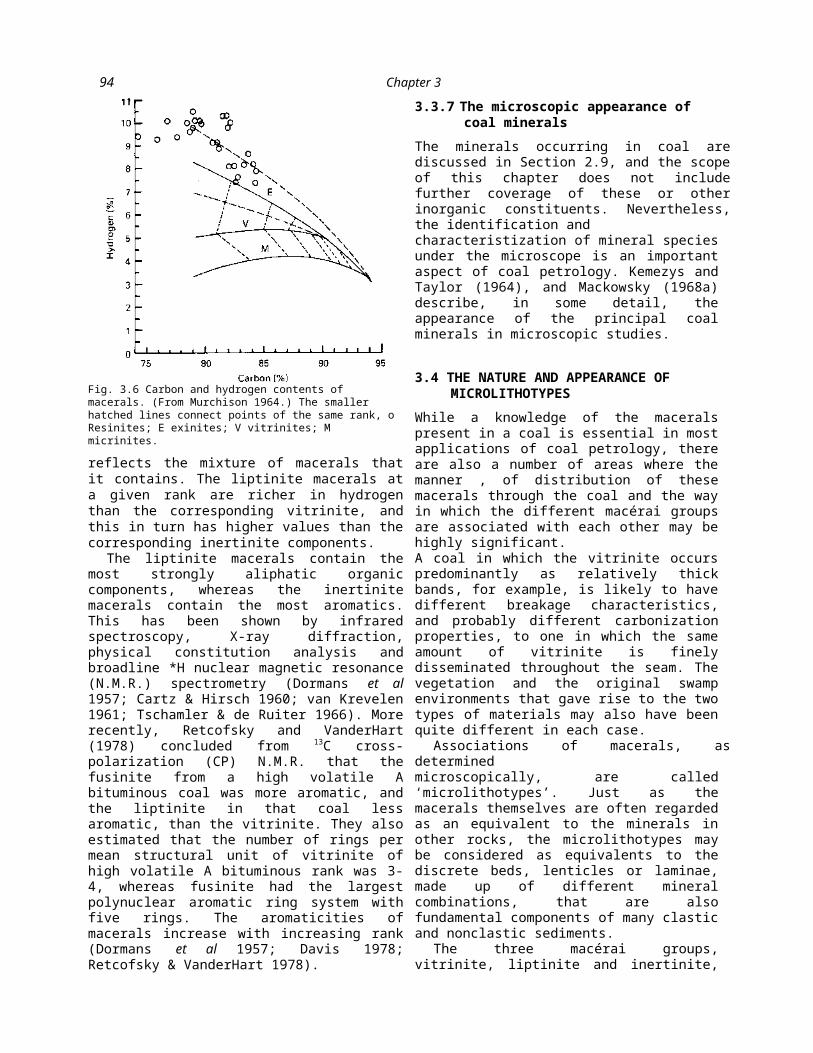
94 Chapter 3
reflects the mixture of macerals that it contains. The liptinite macerals at a given rank are richer in hydrogen than the corresponding vitrinite, and this in turn has higher values than the corresponding inertinite components.
The liptinite macerals contain the most strongly aliphatic organic components, whereas the inertinite macerals contain the most aromatics. This has been shown by infrared spectroscopy, X-ray diffraction, physical constitution analysis and broadline *H nuclear magnetic resonance (N.M.R.) spectrometry (Dormans et al 1957; Cartz & Hirsch 1960; van Krevelen 1961; Tschamler & de Ruiter 1966). More recently, Retcofsky and VanderHart (1978) concluded from 13C cross-polarization (CP) N.M.R. that the fusinite from a high volatile A bituminous coal was more aromatic, and the liptinite in that coal less aromatic, than the vitrinite. They also estimated that the number of rings per mean structural unit of vitrinite of high volatile A bituminous rank was 3-4, whereas fusinite had the largest polynuclear aromatic ring system with five rings. The aromaticities of macerals increase with increasing rank (Dormans et al 1957; Davis 1978; Retcofsky & VanderHart 1978).
3.3.7 The microscopic appearance of coal minerals
The minerals occurring in coal are discussed in Section 2.9, and the scope of this chapter does not include further coverage of these or other inorganic constituents. Nevertheless, the identification andcharacteristization of mineral species under the microscope is an important aspect of coal petrology. Kemezys and Taylor (1964), and Mackowsky (1968a) describe, in some detail, the appearance of the principal coal minerals in microscopic studies.
3.4 THE NATURE AND APPEARANCE OF MICROLITHOTYPES
While a knowledge of the macerals present in a coal is essential in most applications of coal petrology, there are also a number of areas where the manner , of distribution of these macerals through the coal and the way in which the different macérai groups are associated with each other may be highly significant.A coal in which the vitrinite occurs predominantly as relatively thick bands, for example, is likely to have different breakage characteristics, and probably different carbonization properties, to one in which the same amount of vitrinite is finely disseminated throughout the seam. The vegetation and the original swamp environments that gave rise to the two types of materials may also have been quite different in each case.
Associations of macerals, as determinedmicroscopically, are called ‘microlithotypes’. Just as the macerals themselves are often regarded as an equivalent to the minerals in other rocks, the microlithotypes may be considered as equivalents to the discrete beds, lenticles or laminae, made up of different mineral combinations, that are also fundamental components of many clastic and nonclastic sediments.
The three macérai groups, vitrinite,
Fig. 3.6 Carbon and hydrogen contents of macerals. (From Murchison 1964.) The smaller hatched lines connect points of the same rank, o Resinites; E exinites; V vitrinites; M micrinites.

Coal Petrology and Petrographic Analysis 95
liptinite and inertinite, can be associated as shown in Table 3.7 to form a total of seven possible combinations. Three of these combinations are made up of one single macérai group (monomaceral microlithotypes), three contain members of two macérai groups (bimaceral microlithotypes) and the last contains a representative of all three groups (trimaceral microlithotypes or trimacerites).
According to established convention (e.g. I.C.C.R 1971), the association must have a minimum band . width of 50 ¿on before it can be classed as a microlithotype. In addition, constituents that make up less than 5% of the association are normally disregarded. Thus, a band of vitrinite with a small amount of (say) liptinite would not be classed as a clarite unless the liptinite was present in greater abundance than 5%, while a trimacerite must contain at least 5% of each of the three macérai groups.
Low concentrations of mineral matter are usually ignored in the determination of microlithotypes. If

96 Chapter 3
TABLE 3.7 Microlithotypes* and carbominerites.
Microlithotypesall on vitrinite (V) all on V and exinite (E)
on Vs inertinite (I) and E, but with V > I and E on V,
I and E, but with E > V and I on V, I and E, but with
I > V and E
vitrinertiteduriteinertiteliptite
Associations of microlithotypes with mineral impurities (carbominerites) carbargilite carbankerite carbopyrite carbosilicite
*attritus’. In the same manner, fusain bands less than 37 fim thick are arbitrarily assigned as a constituent of ‘opaque attritus’.
Another problem, and one of greater practical importance, is the fact that the system does not lend itself nearly as well to studies of all ranks of coal as does the Stopes-Heerlen system, simply because of the difficulty, and in some cases the impossibility, of preparing thin sections of high rank coals. Also, the C l i t - ci-n/^T7 nrdicVlPfl surfaces has become
JLUUJ V/* -------------------------------
a quantifiable technique through reflectance measurement, while thin section examinations retain the problem of variation in optical properties with section thickness. The Thiessen-Bureau of Mines system is now obsolete in practice, but as a large amount of descriptive work on U.S. coal was done by Thiessen and his colleagues, it is still widely used for review purposes.
3.5.2 The genetic classification of the U.S.S.R.
Academy of Sciences
The lithotypes and microlithotypes of the Stopes- Heerlen system are recognized on the basis of their physical appearance and macérai composition, respectively, and no systematic palaeo-environmental
vitrinertoliptite
all on V and Iall on I and E all on Iall on E -
20-60% (by volume) clay mineral; remainder maceral 20~60% (by volume) carbonate mineral, remainder maceral 5~20% (by volume) pyrite, remainder maceral 20-60% (by volume) quartz, remainder maceral 5-60% (by volume) of various minerals > 60% clay, quartz, carbonate, > 20% pyrite
Coal Petrology and Petrographic Analysis 97
carbopolyminerite ‘dirt’, pyrite
the amount of mineral matter is significant, but the relative density of the microlithotype is less than 1.5, the abundance and type of mineral matter can be described by a qualifying adjective, using terms such as 'argillaceous durite5 (Stach et al 1975). However, where the mineral matter is more abundant, and the relative density of the association lies between 1.5 and 2.0, the material is referred to as a ‘carbominerite’. The types of carbominerites normally recognized, and the volumetric percentages of mineral species that correspond to the
required density range, are also given in Table 3.7. The names of both microlitho-types and carbominerites both have the suffix ending £ite’, as for example, in ‘vitrite’. The methods of microlithotype analysis are discussed more fully
3.5 OTHER CLASSIFICATION SYSTEMS FOR COAL MICROCOMPONENTS
The Stopes-Heerlen system for identification and nomenclature of coal constituents, as described in Section 3.3, is the principal system of classification used throughout the world at the present time.

98 Chapter 3
Because it is based on three maceral groups, vitrinite, liptinite and inertinite, analytical results can be plotted readily in simple representations such as triangular diagrams, yet where greater detail is required, data can be readily extended to encompass the individual macerals or sub-macerals of each group. In this section, however, some other systems used to classify the microcomponents of coal are considered.
3.5.1 The Thiessen-Bureau of Mines system of coal classification
Following very comprehensive studies of coals in thin section at the U.S. Bureau of Mines, Reinhardt Thiessen (Thiessen 1920; Parks & O’Donnell 1956; I.C.C.P. 1963) developed a system of description for the microscopically recognizable ingredients of coal. The three major ‘components’ of banded bituminous coal in this classification can be identified at either the macroscopic or microscopic level. These are ‘anthraxylon’, equivalent to the bright vitrain bands of coal, ‘fusain’,

Coal Petrology and Petrographic Analysis 99
which is much the same as defined in the Stopes-Heerlen system, and ‘attritus’, which is represented by those bands of coal with a dull, prarmlar armearance and consisting of a micro-c*--------- ~r £------------ ------------ ------------o - -------------- -fragmental mixture of varied entities. Microscopic examination of thin sections enables the ‘constituents’ of attritus to be distinguished as either translucent attritus or opaque attritus. Translucent attritus includes spores, cuticles, resins etc., and opaque attritus includes granular opaque matter (micrinite), sclerotia etc.
Table 3.8
summarizes the Thiessen-Bureau of Mines nomenclature and classification, and correlates the terms used with those of the Stopes-Heerlen system. A feature of the Thiessen-Bureau of Mines system is that arbitrary thickness limits were set for some of the components and constituents. Anthraxylon, for example, includes only those vitrain bands greater than 14 ¡xin thick, and any vitrinite with a lesser band thickness would be described as ‘translucent humic degradation matter’, a constituent of ‘translucent

100
Coal Petrology and Petrographic Analysis
TABLE 3.8 Correlation of the Thiessen-Bureau of Mines and Stopes-Heerlen classifications. (Modified after I.C.C.P.
1963.)fusinite less than 37 ¿¿m in width strongly reflecting macrinite strongly reflecting sclerotinite
fusinite and semifusinite more than 37 fim in width
interpretation is implied. Indeed, as can be seen from Section 3.8, there is often no adequate consensus of opinion among coal petrologists regarding the environmental conditions that gave rise to many of the major coal lithotypes. However, at the Institute of Geology, Academy of Sciences of the U.S.S.R., Moscow a genetic classification of microcomponents of humic coals was developed following detailed study of the majority of coal deposits and basins in the U.S.S.R., representing a wide range of tectonic and environmental settings (Timoveev & Bogoliubova 1965; I.C.C.P. 1971).
Within this system, coals are classified according to the material composition of the coal (class and sub-class), and the degree of structural preservation or degradation (group). The horizontal rows in Table 3.9 represent the six ‘classes’ of materials. In thin section, the classes gelinitic, semigelinitic, semi- gelifusinitic, gelifusinitic, quasigelifusinitic, and fusinitic contain materials which vary progressively from red, through brown
to black. This progression reflects increasingly aerobic conditions in the peat bog, due in turn to the degree of flooding and water movement. The processes by which the original ligno- cellulosic plant tissues were transformed into the microcomponents characteristic of these coal classes are seen from the table to be ‘gélification’ for gelinitic
Transmitted lightThiessen-Bureau of Mines System
Bandedcomponents Constituents of attritus
Reflected light Stopes-Heerlen System
MacéraisMacéraigroup
Anthraxylon(translucent)
Translucentattritus
vitrinite more than 14 fim in width Vitrinite
translucent humic matter vitrinite less than 14 ¿un in width
Liptinite
Inertinite
Attritus VOpaqueattritus
spores, pollen, cuticles, algae
cuticles, algaeresinous and waxy substances
brown matter (semitranslucent)
granular opaque matter
amorphous (massive) opaque matter, finely divided fusain, sclerotia
Fusain(opaque)
sporinite, cutinite, alginite
resinite
weakly reflecting semifusinite weakly reflecting macrinite rpfl^rtirta çcWotiniieWwaiMj ivi*wu**p ----------------------------------—
micrinite

Coal Petrology and Petrographic Analysis
101and semigelinitic coals, ‘fusinization’ for fusinitic coals, and a two-stage process of gélification followed by fusinization for the other three classes. A characteristic feature of quasigelifusinitic coals is that they contain large amounts of detrital quartz and clays, as a result of deposition under flooded, running- water conditions.
The vertical columns in Table 3.9 are the genetic ‘groups’ of coal, namely telinitic, posttelinitic, precollinitic, collinitic and leiptinitic. These five groups represent progressively greater physical and biochemical degradation that developed in response to increasing tectonic stability of the area of peat accumulation. In a tectonically stable area of peat accumulation, for example, extensive decomposition of vegetal material would have led to the formation of the collinitic group of coals. Within a tectonically mobile area, by contrast, a more rapid rate of subsidence would have provided greater opportunity for the preservation of plant materials, giving rise to the peats from which the telinitic group of coals would form.
Therefore, in order to classify a coal using this system it is necessary to characterize both the type of substance (class), and the structure (group) of the microcomponents present. Table 3.9 shows how each group is sub-divided into sub-groups based on the class of microcomponents, each of which represents a definable environmental setting. Thus, gelinite- posttelinitic coal, for example, is genetic sub-group representing the product of a heavily flooded, stagnant peat bog within a relatively tectonically mobile area.
Although some of the terms are similar to those in the Stopes-Heerlen system, they are not used in the same way. For example, the term ‘fusinite-telinitic coal’ does not imply the presence of the vitrinite group macérai telinite. Rather it is a coal containing fusinite with a distinct cellular structure. Not only is the U.S.S.R. Academy of Sciences nomenclature used for strictly genetic purposes, but also for the industrial evaluation of coals in that country.
The above description provides only a summary of some of the principal features of the Russian genetic classification, since each of the sub-groups may be further differentiated into several genetic types. The system has not been used extensively outside the U.S.S.R., possibly because of its complexity, while western petrographers are also deterred by the descriptions being based on thin-section examination. Another significant drawback at the present time is that correlations between the genetic coal types and original coal swamp facies have not been confirmed for coal basins outside the U.S.S.R. Nevertheless, the approach and findings of the Russian petrologists should be given careful con-
H
->
•a a
8 'c à T3
I iII
It
? §tji ¡A
.5 V«5 11<2 '3
O .3 <j e
Ü I
U) 3
a I4j %)
Ë. isI I
&„ a §|||O © MH
t- s i3 2 # •8 g?a -i ■H a H2 G
<5 -| 3 ■£ 'K ’55.
-s’ <2 “G U3 W
o
Ja
3■a
■a•a— y1*Sik S;a g.I | i J 1 iu &

102 Chapter 3
sidération in any interpretations of the environments of coal formation.
3.5.3 Spackman terminology and classification
Spackman (1958) noted that each conventional maceral term really represents a suite of materials with greatly varying physical and chemical properties. He therefore considers that is is important to designate macerals by the extent of the metamorphic changes which have occurred. The ending ^inoid5 in, for example, vitrinoid, according to this classification implies a maceral of the ‘Vitrinite
Suite,5 but one with distinctive properties rather than a range such as exists for vitrinite. Likewise, he proposed that there anthracitic vitrinoid with a maximum reflectance in the range 2.20-2.29%. Such categories are sometimes referred to as vitrinoid types or ‘V-types5 (Section 3.7.6). Although it may be useful in aspects of coal utilization (Section 4.3.6), this is a somewhat unfortunate development because it means that vitrinites are not being sub-divided on the basis of the kinds of material involved, but on quite arbitrary divisions of the normal distribution of vitrinite reflectance readings. These divisions may group different materials together, or unnecessarily subdivide portions of the same basic material into differentV-types.
3.6 REFLECTANCE OF VITRINITE AND OTHER MACERALS
The ‘reflectance5 of a maceral or other particle in a coal is the proportion of directly incident light, usually expressed as a percentage, that is reflected from a plane polished surface under specified conditions of
illumination. This property is related to the aromaticity of the organic compounds in the coal concerned, and increases progressively for all macerals as the rank of coal increases.
Precision measurement of the reflectance of individual macerals, particularly vitrinite, is widely used as an index of coal rank. The technique has the advantage over chemical parameters, such as those outlined in Section 2.10, that it is applied to a single selected petrographic constituent, and is therefore not
1 ___!____ ____n*->A fiicinAI/^O flipDe various nntunuiua cum luoiiivi^o nuiuu «.x.w Tnertinite Suite5, and exinoids and resinoids within their own respective suites.
Subsequent usage of the Spackman system seems to have diverged somewhat from this original concept. Schapiro and Gray (1960) established 22 vitrinoids, each with a designation derived from the vitrinite reflectance distribution. Thus, vitrinoid V22 is an

Coal Petrology and Petrographic Analysis
103influenced by the relative proportions of the different macerals within the coal. Considered in conjunction with an index of coal type, such as the actual percentage of vitrinite present, the rank of the coal determined in this way provides an ideal basis for petrographic classification (e.g. Bennett & Taylor 1970).
3.6.1 Theoretical basis of reflectance measurement
Reflectance measurements made with the precision required for coal rank determination are generally carried out by comparing the amount of light reflected from the maceral concerned to the amount of light reflected from a standard substance under the same illumination conditions. Such measurements can be carried out with dry objectives or with water- or oil-immersion lenses, but most studies employ an oil-immersion technique, using an oil with a refractive index of 1.518 at 23°C and an incident light wavelength of 546 nm. The amount of light reflected from the surface of the maceral is determined from the electrical output of a photomultiplier system (Section 3.7.6), and the reflectance can be calculated from the following formula:
As
where R = reflectance of the coal maceral; Rs = reflectance of a calibration standard; A = deflection of galvanometer, chart recorder etc. of photomultiplier system for the maceral; and As = deflection of galvanometer, chart recorder etc. for the calibration standard. In most cases, however, the petrographer sets the reflectance of the standard as the galvonometer reading, so that the reflectance is read directly.
The relationship between reflectance (R) and the other optical properties of both the reflecting material and the immersion medium can be expressed by Beer’s equation as follows:
(n - nxf + w2k2 ^ (n + nx)2
+ n2 ke
where n = refractive index of reflecting material; k = absorption index of reflecting material; and nx = refractive index of medium in which the measurement is made.
The refractive index of immersion oil changes with temperature, and this in turn influences the value obtained in reflectance measurement. In order to

104 Chapter 3
obtain a value of the relectance in oil (RJ corrected to a standard temperature (23° or 25 °C), it is necessary, in theory, to measure the reflectance in two media (air is convenient as the second) and calculate n and k from the
following equations:
1 /..2 2 -
»i a+ *0)/(i - Ro) -(! + R ) / ( i - R )
and
k2 = jg, ( n + l) 2 - ( n - 1 f
» 2 (1 - R )
where i? = measured reflectance in oil; R =
o y a
measured reflectance in air; and n 1 = refractive index of oil at temperature of measurement.
Substituting the calculated values for n and k and the known value of n x at 23 °C (usually 1.518) into Beer’s equation above allows the calculation of R o (23 °C). Note that the reflectances in these equations are expressed to unit base, rather than as percentages.
In practice, such computations are seldom performed. Instead of correcting for the actual oil temperatures, the R o of glass calibration standards is calculated from their refractive indices using the Fresnel equation, with a value of 1.518 assumed for »r
R = (”s - X 100S (»2 + «1 f
where R s is the reflectance of the standard expressed as a percentage, n 2
is the refractive index of the glass, and n 1 is that of the immersion medium.
Obviously, if the reflectances of the maceral being measured and the standard used for calibration are very close, any variation in refractive index of the oil due to a change in temperature from 23 °C will cause both to vary by similar amounts. However, if the coal and the standard have widely differing reflectances, any variation in refractive index of the oil will introduce significant errors. Consequently, it is
customary to calibrate reflectometer systems with standards whose reflectances have been calculated using n0 = 1.518, and which are close to those of the macerals under study.
3.6.2 Optical anisotropy of reflectance
Vitrinite in coal often displays a three-dimensional variation in reflectance that is similar to the variation in optical properties exhibited by uniaxial negative
n =
Fig. 3.7 The anisotropic character of coal. 7?and R are the maximum and minimum reflectances of vitrinite, respectively. R is an apparent minimum reflectance, intermediate between R and R

Coal Petrology and Petrographic Analysis
105substances. The optic axis of the indicatrix in these circumstances is approximately normal to the bedding plane. The vertical axis is shorter than the two horizontal axes, mainly in response to the vertical stresses imposed by the weight of superincumbent strata (Fig. 3.7).
When viewed under plane polarized light, all planes or sections through a given layer of vitrinite, according to this model, should display the maximum reflectance of the material in at least one orientation on the microscope stage. A section cut perpendicular to bedding should display the maximum reflectance when the plane of polarization of the light is along the bedding trace and the minimum reflectance of the material when it is at right angles to this direction. A section cut parallel to bedding, on the other hand, theoretically should exhibit the maximum reflectance in any orientation, while one that is oblique to bedding should display the maximum reflectance when the light is polarized along the bedding trace and a value intermediate between the minimum and the maximum (i.e. an apparent minimum) when it is at right angles to the bedding.
In a grain mount made up of crushed fragments of the coal embedded with random orientation in a plastic binder, every vitrinite particle examined should exhibit the maximum reflectance in at least one position during rotation of the microscope stage when the field is illuminated with vertically incident

106 Chapter 3
plane polarized light. The value of this maximum reflectance can be recorded for a large number of particles and the ‘mean maximum reflectance5 (Rmax) calculated to give a widely used rank parameter.
If the reflectance is measured in non-polarized light, on the other hand, the reflections from all directions on the vitrinite surface will be integrated to give a ‘random reflectance5. Figure 3.8 compares the influence of the reflectance anisotropy of a surface upon reflectances obtained in polarized and non-polarized light. A statistical mean of random (non-polarized) readings taken on many vitrinite particles in a polished grain mount of a coal theoretically gives the same value for the random reflectance as would be obtained if the random readings were taken in polarized light (without stage rotation). However, the range of theoretically possible values from a sample is much less for non-polarized iigbt [ R
m„ t0 (Rmax + R min)/2 1 than for
polarized light (Rmax to Rmin)- The statistical relationship between random, maximum and minimum reflectances (Hevia & Virgos 1977) is also shown in Fig. 3.8. Davis (1978c) has summarized the relative merits of maximum and random reflectance determinations in coal petrographic studies.
Not all coals display uniaxial reflectance characteristics. Hevia and Virgos (1977), Cook et al (I98la) and Levine and Davis (1984) have all reported the existence of coals that demonstrate a biaxial anisotropy. An important implication of this observation is that not all coal sections need necessarily display the maximum reflectance value. Most of the above reports describe biaxial negative
coals, but Levine and Davis (1984) have also reported a sample of low volatile bituminous coal from Pennsylvania that had the characteristics of a biaxial positive material.3.6.3 Vitrinite reflectance and coal rank
The reflectance of vitrinite, as well as that of other macerals, particularly those of the liptinite group (see below), increases progressively with the rank of the coal in which it occurs. Figure 3.9 illustrates the relation between the maximum reflectance of vitrinite and the carbon content of the same material (another rank indicator), arid Table 3.10 gives an indication ofthe ranges of mean maximum vitrinite reflectance (£max) that correspond to the principal A.S.T.M. rank designations, based on other parameters as outlined in Section 2.10.2. The rate of change of reflectance is not uniform with respect to many of these other indices, and, in
fact, reflectance is a sensitive indicator of rank change in higher, rather than lower rank deposits.
Figure 3.9 also shows the variation in minimum reflectance, and hence, from the difference between maximum and minimum reflectance, the ‘bi-reflectance5 of the vitrinite. This latter property also increases significantly with rank, although, as discussed furtherin uiv.iv, io uvn nv,vv,ooai relation between rank and anisotropy in some individual coalfields.
(iy/z/, ¿none anu ^OOK nuwer anu i^avis n iimiÀ' ........
a uiiuui in/1 . .. . . . J 1_ /1 A rjA\ TT_____________________ _________I T"\_________* _
Coal Petrology and Petrographic Analysis
1073.6.4 Reflectance of other macerals
(a)
Figure 3.10 shows the random reflectances of fusinite,(b)
Fig. 3.8 Random reflectance in polarized and non-polarized light. In polarized light, the random reflectance obtained on a single particle would vary between R and R' - , the apparent minimum reflectance, depending upon the orientation of the particle. In non-polarized light, the reflectance in all directions will be integrated into the random reflectance reading, regardless of orientation. The relationships shown are from Hevia and Virgos (1977). (a) Polarized light, (b) Non-polarized light. _ _R^rcpraaite the average of a number of readings. Rnild ^ = Rrand = (2Rmax + Rmin)/3;
^rand non-pol ^ av “ ^max + ^ min

108 Chapter 3
Fig. 3.9 The relationship between carbon content andmaximum (•) and minimum (o) reflectances of vitrinite. (From Davis 1978.)
TABLE 3.10 Vitrinite reflectance limits (in oil) and A.S.T.M. coal rank
classes.
semifusinite, micrinite and sporinite relative to that of vitrinite in a number of coals. The reflectance of fusinite approaches that of vitrinite as rank increases, and in the case of a peranthracite (Alpern & Lemos de Sousa 1970) the fusinite may actually have a lower reflectance than the vitrinite in the same coal.
The coalification track of sporinite
displays a sharp increase in reflectance, known as the ‘coalification jump’ (Stach & Michels 1955), at a rank corresponding to a vitrinite reflectance of about 1.2%. The reflectances of these two macerals then merge at a vitrinite reflectance of about 1.5%. The
reflectance of resi- nite is similar to that of sporinite in the same coal, while that of cutinite is somewhat higher. Cutinite also exhibits a strong reflectance anisotropy. Hower (1978) has described liptinite macerals (sporinite, resi- nite and cutinite) in an anthracite sample, all with similar random reflectances of about 4.9%. The bireflectances of the liptinite macerals, especially the cutinite, in this case were greater than that of the vitrinite.
3.6.5 Reflectance at different wavelengths
Figure 3.11 shows that, for bituminous
4.01-
0 > « ■ » ■ ! _________I __» ■ « » « « _I l___________i _t i l l ____I __I _______I __1 __l 1 _70 75 .80 85 90 95Carbon (%)
Fig. 3.10 Reflectances of different macerals through a range of coal rank. (From Hoover & Davis 1980.) • Vitrinite; □ sporinite; A fusinite; A semifusinite; o micrinite.
Rank Maximum reflectance (%)
sub-bituminous <0.47high volatile bituminous C 0.47-0.57high volatile bituminous B 0.57-0.71high volatile bituminous A 0.71-1.10medium volatile bituminous 1.10-1.50
low volatile bituminous 1.50-2.05semianthracite 2.05-3.00 (approx.)anthracite >3.00 (approx.)

Coal Petrology and Petrographic Analysis
109coals, the reflectances in air and oil, and the refractive index of vitrinite, decrease with increasing wavelength of the incident light. With increasing rank, the dispersion curves for air reflectance and refractive index tend to flatten, and, in the case of anthracites, there is a reversal in slope, so that values increase towards the red end of the spectrum.
From the visible region of the spectrum into the ultraviolet, the reflectances and refractive indices of vitrinites have been observed to decrease. The absorption coefficients, however, tend to peak within the ultraviolet region near 280 nm, extending into the visible range in the case of anthracites (Gilbert 1962; McCartney et al 1965). This strong absorption in the ultraviolet has been interpreted as being due to the presence of significant proportions of aromatic structures. The different slopes of the dispersion curves for vitrinites of varying rank, relative to the slope for a calibration standard, provide a compelling reason why reflectance measurements should be made in monochromatic light.
Murchison and Jones (1964) and Hevia (1974) have shown that the
shapes of the dispersion curves for liptinite macerals are fairly similar to those of vitrinite from the same coal, although, of course, displaced to lower values. The curves for inertinite macerals are less steep than those of the vitrinite; those of higher reflecting inertinite have very low slopes, and some display minima in the range 480-550 nm (Hevia 1974).
i 7 DPTDnnu APuir ANAT V«KM. AJ 1 111V« lllUllilk/lU
Micropetrographic study of coal may be used either as a technique of quality evaluation in the testing of a coal’s economic value, or as an aid to understanding the geologic history of the material. Though the selection of samples to be studied in each case may be somewhat different, both types of study generally involve measuring the relative proportions of the various macerals and/or microlithotypes that may be present, and assessing the rank of the coal by means of such properties as vitrinite reflectance.
The actual techniques involved in such studies are similar in many ways to petrographic methods used in other branches of geology, although a number of refinements have been introduced to deal specifically with coal and related materials. As with other aspects of coal analysis, several international and national standards are available that describe the most appropriate procedures in some degree of detail. In other cases, such as with the introduction of automated microscopy to coal petrography, much of the necessary information can only be found in the discussions of various research investigations.
3.7.1 Sample preparation
As indicated in Section 3.3, almost all petrographic studies of coals are now carried out by means of polished section techniques. Polished sections of coal may be prepared from single lumps, broken pr sawn from a hand
1.701----------------1------------------1----------------1----------------*600 550 500 450 400Wavelength (nm)Fig. 3.11 Dispersion of the optical properties of vitrinites (From Davis 1978.) (a) Air reflectance, (b) Oil reflectance.(c) Refractive index, o 82.6-83.4% carbon; A84.0% carbon; A87.7~88.1% carbon; ■ 91.4% carbon; □ 92.8% carbon; • 92.8%~93.3% carbon.

110 Chapter 3
specimen, a section of drill core or an exposed coal face, or they may be prepared from a representative sample of the seam or seam sub-section, crushed to a granular or coarse powder form. Individual lump specimens have the advantage that they can preserve the geometric relationships of the various bands and other masses in the coal to a greater extent than crushed coal samples, but have the disadvantage that they only represent a limited sub-section of the seam in question. A relatively small amount of a well- prepared, representative crushed sample, on the other hand, can provide data on the abundance and optical characteristics of the macerals or microlithotypes present in a much larger mass of in situ or mine product material.
Lump specimens for polished blocks are usually air-dried and impregnated with an appropriate resin if necessary to provide strength. The specimen is then trimmed to expose the. face to be studied (usually one perpendicular to the bedding planes), and mounted in an appropriate mould with a cold-setting resin material. Once set, the embedded specimen can be ground or cut along the desired plane, and polished with successively finer abrasive powders.
Crushed coal specimens for petrographic study are usually prepared to a coarser particle size than are samples for many other analyses. For most purposes, a maximum particle size of 1 mm is required, compared to 200 fim for (say) proximate analysis, but it is also necessary to produce a minimum amount of fine material in the crushing process. These requirements should be taken into account when designing the sample preparation sequence for a coal analysis programme in which
petrographic studies are to be included at some stage.
The crushed material is well mixed with a coldsetting resin to form a paste or slurry, and the mixture poured into a mould of appropriate shape to harden. Care should taken to avoid the solid particles settling and segregating before the binder has set. Once set, the moulded resin and coal pellet is ground and

Coal Petrology and Petrographic Analysis
111polished for petrographic examination. If any segregation of panicles has occurred, the pellet should be cut in the vertical plane and one half polished. An alternative procedure is to employ a hydraulic press to prepare cylindrical moulds in which close packing prevents segregation. Grinding and polishing are carried out with a senes of abrasives on wet laps of low-nap cloth and/or silk. A high quality of relieffree polish is required for reflectance determinations.
The techniques of polished section preparation are described in some detail by the I.C.C.P. (1963), Stach et al (1975), A.S.T.M. (1981a) and the International Organization for Standardization (I.S.O.) (in preparation, a). Although much less widely used, the methods of preparing coal thin sections for microscopic examination are given by Thiessen (1920), van Krevelen (1961) and Francis (1961).
3.7.2 Maceral analysis
The relative proportions of the various macerals in a coal, at least on a volumetric basis, can be determined from either polished blocks of lump coal or grain mounts by the techniques of modal analysis. In the past, this has included ‘lineal analysis’ by means of the integrating stage (van Krevelen 1961; Galehouse 1971)
m r \ T - t - T - i c it*v> nrro KaManf-U tUa atTamaan K.r n nam/vivYiuvix iiiuv^u Liiv linage L/v.ixc-aLii LIIV uy a. otiltd
of micrometer-graduated screw spindles. Each spindle was moved only when a particular maceral was under the cross-hair in the field of view. At the conclusion of the examination, the amount of each maceral present was determined from the contribution that each spindle had made to the total traverse length.
Today, however, modal analysis is more commonly based on the
technique of point counting (Glagolev 1934; Chayes 1949, 1956), in which the microscope stage is moved in a series of fixed increments and the identity of the maceral falling beneath the cross-hairs after each advance is recorded. The volumetric abundance of each maceral is determined from the total number of points at which it was encountered in relation to the total number of points recorded in the traverse network.
Stage movement can be
accomplished manually with a mechanical stage equipped with check stops, or even by visually adjusting the stage vernier scale. However, there are automatic point counters such as that displayed in Fig. 3.12, which keep a tally of the number of counts made on each maceral and also activate the stage advance mechanism each time a counter is depressed, moving it on to
Mg. 3.12 Microscope equipped with Swift automatic point counter.
1/2E95 = 2
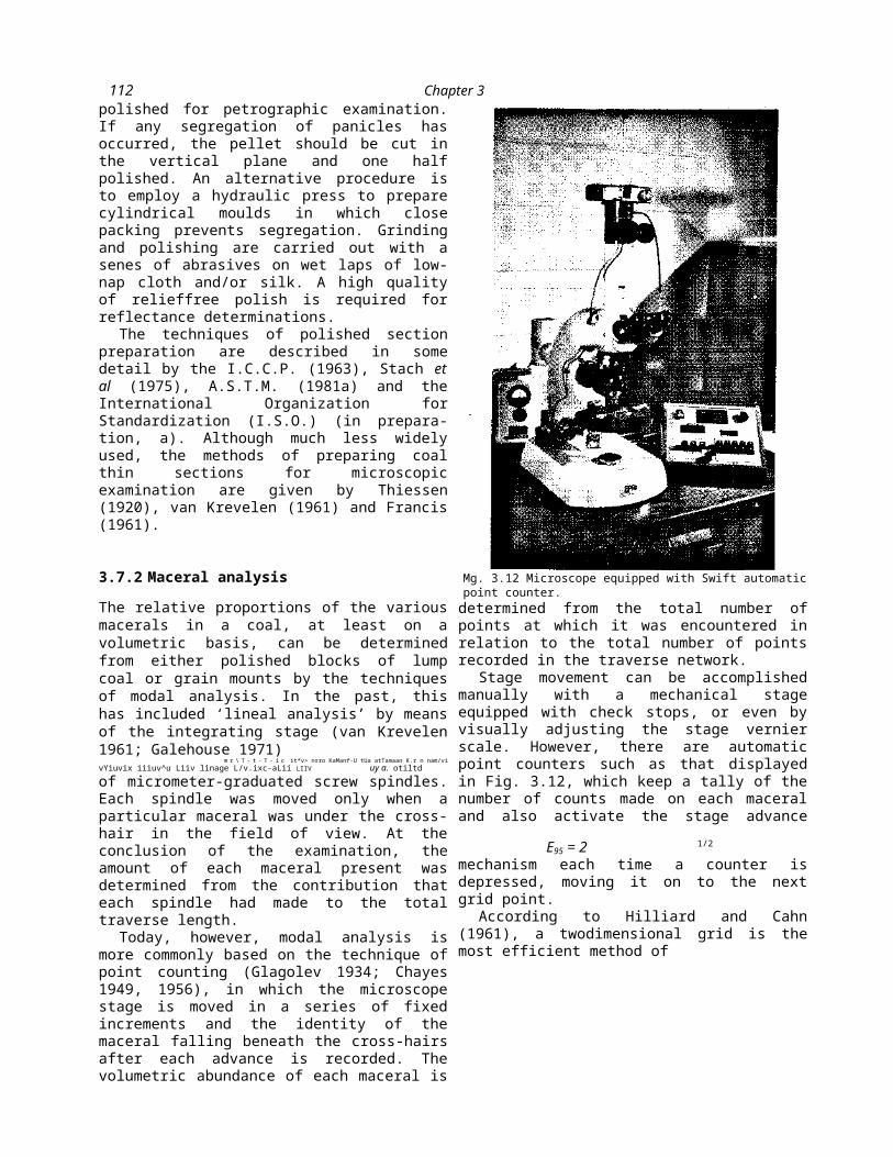
112 Chapter 3
the next grid point.According to Hilliard and Cahn
(1961), a twodimensional grid is the most efficient method of
analysing volume proportions, with a grid spacing such that the majority of structural features should be intersected by no more than one grid point. The I.S.O. (in preparation, b) recommends that maceral analyses should be performed on minus 1 mm coal particles, and, with the I.C.C.P. (1963), that interpoint and inter-line distances should be approximately 0.5 mm. The probable error, at the 95% confidence level, involved in counting individual components (E95) is given by the equation
P (loo - p )
where p is the percentage of the individual component, and n is the total number of points counted.
For components present in proportions of 10, 50 and 90%, the probable errors involved in a maceral analysis of 500 points are ± 2.7, 4.5 and 2.7%, respectively, assuming of course that no errors in identification are made during the analysis. The repeatabilities of such results (2F/V2) are 3.8, 6.4 and 3.8, respectively. The reproducibility, that is the difference between results of two different operators

Coal Petrology and Petrographic Analysis
113analysing different sub-samples of the same coal, has been found to be about 1.5-2 times the theoretical repeatability (I.S.O., in preparation, b). Thus, maceral percentages should be reported to the nearest integer and not, as is frequently done, to the first decimal place.
The total number of points counted in maceral analysis can vary according to the standard procedure followed, the purpose of the analysis, and the accuracy desired. Galehouse (1971) provides useful nomograms and tables for determining quickly the number of points that must be counted in order to achieve desired levels of accuracy. The I.C.C.P. (1963) recommends counting 500 or 1000 points to give an accuracy of about ± 2-3%. I.S.O. (in preparation, b) requires that at least 500 points be counted. The A.S.T.M. (1981b) standard deals with precision in maceral analysis by requiring that two separate analyses of 1000 points be performed on each of two grain mounts. For the values to be acceptable, the mean difference between maceral percentages of the two grain mounts should not exceed 2%.
The magnification employed for maceral analysis should be such as to permit resolution of most maceral occurrences, i.e. at least x200 overall. However, A.S.T.M. (1981b) recommends that it should be greater than X400. Oil immersion objectives are normally used to provide best identification conditions.
Selection of the macerals or maceral groups and, if desired, the mineral species to be counted depends upon the purpose for which the analysis is intended and the predilections of the petrographer. Some laboratories count only the three maceral groups, whereas the A.S.T.M. standard specifies the six macerals that should be counted.
Various conventions can be adopted to help the netrwranher maintain consistency in those instancesI ------O- -1 ----- --------------- ------------ - J - - - - - -
where the cross-hair lies over the perimeter of particles or on boundaries between macerals (Stach et al 1975;
I.S.O., in preparation, b).
3.7.3 Combined white- and blue-light petrographic analysis
Fluorescence microscopy can enable distinctions to be made between liptinite macerals which would other-wise appear uniformly dark in reflected white light. Also, in petrographic analyses performed in blue light, the percentages of the fluorescent liptinite macerals often appear greater than when conventional white light is used. Identification is made more readily by observing the fluorescence colours on a dark background than by observing the dark reflections on a medium background.
Table 3.11 provides a comparison of selected analyses carried out both in white and combined white and blue light, showing the larger proportions of liptinite macerals which were recorded in the combination analysis (Davis 1975). In the combination analysis, the percentages of liptinite macerals were determined in blue light, and the balance, due to nonfluorescing vitrinite and inertinite group macerals, apportioned according to the results of the white-light analysis.
3.7.4 Bases for reporting maceral analyses
Petrographic analyses are reported on either a mineralfree or mineral-containing basis. For the latter, the amount of mineral matter may be determined together with macerals during point counting, or calculated using an empirical formula. Direct determination using techniques such as radio-frequency oxidation is also possible (Section 2.9.2).
Some difficulties are associated with the determination of mineral percentages by modal analysis. Certain minerals, including quartz and the volumetrically important clay minerals, often appear dark, almost black, under oil immersion. It is therefore possible to mistake them for voids or for the resin binder, esneciallv where there is no surrounding matrix of--r---------J - - - - - - - - - - - - (_j --------------

114 Chapter 3
higher reflecting coal macerals to provide an optical contrast. Other minerals, including pyrite grains, may be plucked out during polishing, so that their proportions may tend to be underestimated. In some instances, the minerals are so finely divided that it is impossible to resolve them under the microscope, while much of the inorganic content of lower rank coals also exists as ion-exchangeable cations within the organic molecular structure rather than as discrete mineral species.
In spite of these difficulties, it is often useful to include ‘total minerals’ as a category in the pointcount analysis, or even to count individual classes of minerals, such as clays, carbonates, pyrite, quartz etc. Several formulae have been developed to calculate the volume percentage, rather than mass percentage, of mineral matter in coals. The A.S.T.M. (1981b) equation below is based on the Parr formula (Section 2.9.2), and average densities of 2.80 and 1.35 have been assumed for the mineral and organic contents, respectively, to convert the mass of mineral matter to a volume percentage.
_ _________100 [(1.08A + Q.55S)/2.8]_________(VOl) [100 - (1.08A + 0.55S)]/1.35 + (1.08A - 0.55S)/2.8
when A and S are the ash and sulphur values of the coal, respectively, expressed on a dry basis.

Coal Petrology and Petrographic Analysis
115
The I.S.O. (in preparation, b) has simplified this to:
• MM, = MMD(vol) _________________________p_____________
2.7 - (0.011 MMp)
where MMp, the weight percentage mineral matter, is derived through the Parr equation and equals 1.08A + 0.55S.
An empirical equation has also been given by I.S.O. (in preparation, b) as follows:
MM, n = 0.61A - 0.21(vol)
Benedict et al (1968) have used the equation below as a simple method for estimating the volumetric mineral content of coals:
MM(voI) = 0.6 (A + S)
where A and S are as defined above.Occasionally, the results of maceral
analysis are reported on a weight percentage basis. To do this one must assume a value for the relative density of the macerals at the particular rank level of the subject coal. The I.C.C.P. (1963) lists densities for five macerals at 19 rank levels, based on the percentage of total carbon. Table 3.12 gives a comparison of a single maceral analysis reported on a volume percentage mineral-free basis, a volume percentage mineral- containing basis, and a weight percentage mineral- containing basis.
3.7.5 Microlithotype analysis
Although the technique is not as widely
used as maceral analysis, the relative proportions of the various microlithotypes and, if necessary, of carbominerites (coal-mineral associations) in a coal sample can also be determined by modal analysis methods. In the most common of the two analysis techniques, the microscope eyepiece is fitted with a 20 point cross-line reticule (Fig. 3.13). The magnification characteristics of the microscope are matched to the actual size of the grid to delineate a 50pm square
TABLE 3.11 Comparison of white-light and combined white- and blue-light maceral analyses (PSOC-123; lithotype of No. 5. Block Seam, West Virginia; Ro = 0.71%).
Analysis Vitrinite Sporinite Cutinite Resinite Alginite Fusinite Semifusinite Macrinite Micrinite
White light (%) Combination
37 240 2 0
15 4 5 13
(white/blue) (%) 29 331 6
311
3 410
116 Chapter 3
in the field of view, normally with a x25 objective being used. Each band or maceral association falling within this square can be evaluated in terms of size (i.e. if it is greater than 50 pm in thickness) and also with respect to the relative proportion of the various constituents. For example, if all 20 points on the reticule fall on vitrinite, the microlithotype has less than 5% of any other maceral group and is therefore classed as a vitrite. If one or more of the 20 points coincide with inertinite, however, the material would be classed as a vitrinertite (Table 3.7).
Each observation on a group of 20 grid line intersections is regarded as a point, even though the area covered may in fact cross the boundary between two different naturally occurring microlithotype bands. At least 500 points should be counted to achieve a satisfactory result, with care being taken to ensure that the whole of the specimen’s surface is covered to avoid any bias due to particle segregation. The I.C.C.P. (1963) and Stach et al (1975) describe conventions that should be followed when the reticule does not fully cover the image of a coal particle, and lies partly on the binding material of the crushed coal specimen.
The second method of performing microlithotype analysis is termed ‘selon la ligne’ (according to the line). A simple eyepiece measuring reticule is used, with divisions spaced equally such that at least 20 fall within 50 pm. In the case of particulate samples,
X
\
Fig. 3.13 Twenty point eyepiece reticule for microlithotype analysis.
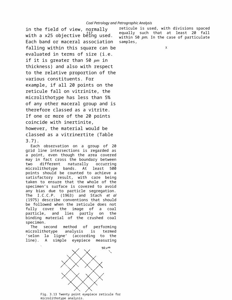
' Coal Petrology and Petrographic Analysis117
the reticule is rotated so that the line lies perpendicular to the bedding displayed in any particle. Microlithotype identification is made by considering the ‘natural band5 of 50 pm in width containing the mid-point of the reticule. The 5% limit is determined by estimating the proportion of macerals or minerals across the width of the band under consideration. Where stratification is uncertain, the reticule shouldt__ _______J : — ________i______________________________*.u~
uc maiiuanicu m me vcmuai piuMiiuii aiiu uicestimation made on a circle of radius 50 pm.
The ‘selon la ligne5 method is also particularly suitable for obtaining microlithotype profiles of column samples of coal. A traverse can be made down the entire column of coal, a reticule length at a time.
Analysis by either method on the same coal will give different results, because the 20 point ocular method, which does not recognize ‘natural bands5 in the sample, tends to produce more bimaceral and trimaceral categories. J.W. Hunt (personal com-munication) has, in comparing the two methods on the same sample, measured the amount of vitrite + duroclarite + clarodurite by the ‘selon la ligne5 method at 30%, compared to 45% by the 20 point ocular method.
3.7.6 Reflectance measurement
A number of methods, both direct and indirect, have been employed to measure the reflectance of coal macerals, and these are reviewed by Davis (1978c). Of these techniques, however, the single-beam comparative method is now used by most, if not all, coal petrologists throughout the world.
The single-beam comparative method is based on the use of a reflected-light microscope photometer,
calibrated by means of glass, mineral or synthetic standards, which are then replaced by the vitrinite in the coal sample for a series of reflectance readings. Detailed descriptions of the equipment and procedures used in the process are given by the I.C.C.P. (1971), Galopin and Henry (1972), Piller (1977), A.S.T.M. (1981c) and I.S.O (in press, c). The components of a reflectance photometer are illustrated in Fig. 3.14.
The light source must be stabilized to ensure that no variations in photomultiplier output arise due to minor fluctuations in light intensity with surges
AI
Quartzhalogen
lamp
Vitrinite Fusinite Semifusinite Macrinite Micrinite Sporinite Resinite Mineral
Volume (%), mineral-free 81 9 4 1 1 3 1
Volume (%), mineral-containing 79 8 4 1 1 3 1 3
Weight (%), mineral-containing 75 9 41 1
31 6
TABLE 3.12 Maceral analysis reported to different bases [high volatile B bituminous coal (PSOC-68)].
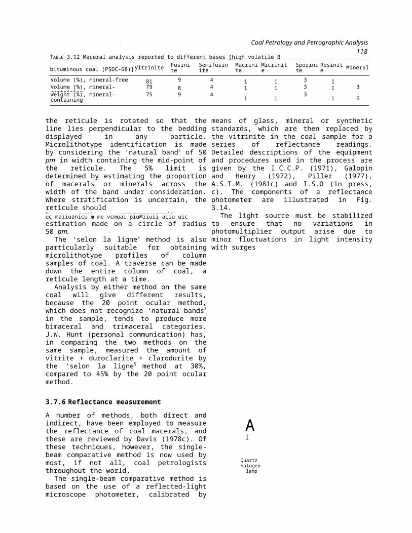
118 Chapter 3
in the power supply. Because the amount of light reflected from the coal is rather small (usually less than 2%) the power rating and intensity of the light source should be high to increase the signal-to-noise ratio of the system. A 100 W quartz-halogen lamp is most commonly used for this purpose.
If ‘maximum5 rather than ‘random5 reflectance is to be measured, a polarizer is placed into the
< 4 1 « T « + « « * > • * / % A / 4 / \ f / \ f U A
U 1 G 1 U C 1 U l l g l l l U C c U l l . J _ t l g l l l I di C l l C ^ L C U U i l I U l l i ^
specimen surface by means of a vertical illuminator. In microscopes that use a Berek prism as the vertical illuminator, the polarizer should be set in the 45° position (Berek 1937; Broadbent & Shaw 1955).
The reflected light from the surface of the coal passes back through the objective to the vertical illuminator. Between the vertical illuminator and the photomultiplier head are a filter and a limiting aperture. The filter is usually a band interference filter of 546 nm, which is the wavelength of the mercury line within the green region of light. The aperture, which may be of fixed or variable dimensions, limits the area of the field on which the reflectance measurement is actually taken. A square of about 4-5 ^m on the side is most commonly used. In many modem photometric systems, an image of the aperture can be seen superimposed upon the actual area of measurement within the field of view.
The measuring device used in most reflectance systems is a photomultiplier tube, selected to given mnnAnna nt n m T^irritvll nVlAtAn AA11 n tpl*cCt illgll itopuiiov UL 11111. l-'lglLai ^HVLWll VVSMlllW
(Gray Todd & Drexler 1979) and photodiodes (Otte & Pfisterer, in preparation) have also been used as satisfactory alternatives for this purpose. A stablized power supply is required for the photometer. A chart, meter
Photomultiplier cathode ^Interference filter— ezzza
Magnification system * with limiting aperture
Polarizer
Dl'ild \Vertical illuminator
Objective-^--^
Specimen *rr77-rr
Fig. 3.14 Optical components of a microscope photometer.
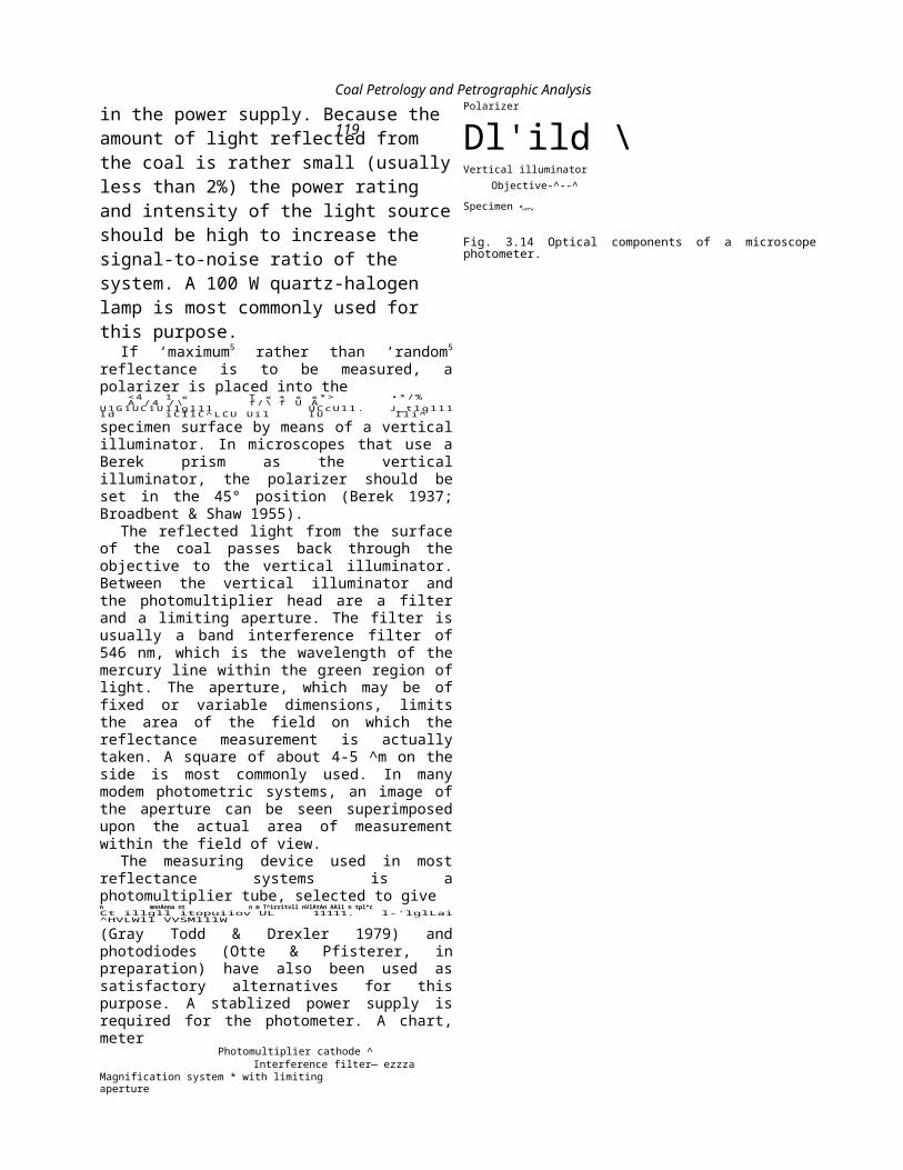
Coal Petrology and Petrographic Analysis
119or computer is needed to observe and/or record the reflectance readings, and a data processor is often an integral part of the reflectometer system.
The scale on which the reflectance measurements are read is established from zero to the reflectance of the primary standard, preferably one which has a reflectance just slightly above that of the subject vitrinite (Juckes 1973). The reflectance of glass standards (R) can be calculated from the Fresnel equation (Section 3.6.1), but, because there is some indication that the surface properties of materials may also influence their measured optical properties (Piller 1977), they may be calibrated by the supplier. It is possible to obtain or prepare single mounts which contain a number of such standards if required.
Once the upper limit of the scale has been calibrated the zero should be corrected for any photomultiplier dark current and back reflectance (primary glare) from the back lens of the objective (Kotter 1960; Jones 1962; Galopin & Henry 1972; Piller 1977). At least one additional standard should be checked against the scale and the calculated (or calibrated) and determined values should not differ by more than about ± 0.02% actual reflectance.
Suitable vitrinite particles are selected for measurement from a grain mount which has been carefully polished to give a level, scratch-free and relief-free surface (A.S.T.M. 1981c). A recommended practice is to select the particles from a grid pattern covering most of the grain mount. All of the various vitrinite macerals and sub-macerals might be included for applications where coal properties are being related to technological behaviour, such as carbonization. However, for precise measurements of the degree of metamorphism it may be best to restrict the measurements to bands of homogeneous telocollinite, which tends to be slightly more highly reflecting, rather than the more heterogeneous desmocollinite. In the case of lignites, the preferred vitrinitic, or huminite maceral for reflectance
measurement is ulminite.The number of readings that must be
averaged to obtain the mean reflectance may vary, depending on the application, between about 20 and 100. Obtaining a reflectance distribution chart on a blend of two or more coals, however, may require 500 or more readings. Checking and adjusting the calibration of the microphotometer should be done at intervals during the analysis, and also at its conclusion. The standard deviation of the mean for 100 readings on a single seam should be about 0.01-0.02% (I.C.C.P. 1971; I.S.O., in press, c). The reproducibility between two different operators analysing sub-samples of the same coal might be 0.08%.
In addition to reporting mean reflectance, it is also common for the reflectance distribution to be reported as £V-types’ (vitrinoid types), or V-types’, which represent ranges 0.1 and 0.05%, respectively. For example, V-type 7 covers the reflectance range 0.70-0.79%, and % V-type 7.25 covers the range 0.70-0.74%. Figure 3.15 is a histogram plot of a lh V-type distribution. Reference to Table 3.10 (Section 3.6.3) indicates that this particular sample is a blend of medium, high and low volatile bituminous components. The use of such data in establishing the coking characteristics of a coal or blend is discussed further in Section 3.9.3.
3.7.7 Automated microscopy of coal
A number of methods are under investigation to provide automatic microscopic measurement of the petrographic properties of coal. The principal goal of research with these systems is to develop the capacity of performing rapid and accurate maceral analyses, based on the characteristic differences in reflectance of the various components in a single coal. These techniques have the potential to provide improved reproducibility due to the removal of operator-induced sources of variation, and also enable a greatly increased number of sample points to be investigated ner unit time.

120 Chapter 3---*------C?- *" 1* - •* _ _
Davis (1978c) has reviewed many of the early attempts to automate coal petrographic analysis, including the clockwork stage and recording device of Vendl (1934) and the AMEDA, which incorporated ten electronic counters and a belt-drive stage mechanism (Bomberger & Duel 1964; Bayer et al 1968). Most of these, however, were limited by the data-handling capacity of the instruments used. A
Fig. 3.15 1/2 V-type reflectance histogram for a blend ofhigh, medium and low volatile bituminous coals. Sample: coal blend. i?max
= 1.245%.

Coal Petrology and Petrographic Analysis
121system developed by the U.S. Bureau of Mines (McCartney & Ergun 1969; McCartney et al 1971) also employed continuous scanning, and recorded reflectance data on magnetic tape for subsequent computer processing. Three generations of automated microscopes, using both continuous and stepping stage movement with data processing in real time, are described by Davis and Vastola (1977), Kuehn and Davis (1979) and Hoover and Davis (1980).
Although the instruments used in modern automated microscopy vary considerably, they can be classified into two types, image-plane or specimen- plane scanners, on the basis of the type of scanning technique employed (Weibel et al 1972; Kuehn & Davis 1979). In image-plane scanners, the scanning is performed by a sensor on the video projection of the microscopic image, and for this reason, techniques of this type are known as image-analysis systems. Many thousands of points are analysed for each field, but reproducibility of results is also a function of the number of fields analysed during a scan. Such systems have the advantage of being able to analyse the size and shape of the particles under investigation. Various applications of the technique to coal and coke petrography are described by B.C.R.A (1975), Harris (1977), Harris et al\ (1977), Zeiss (1979) and Chao et al (1979).
With specirnen-plane scanners, on the other hand,
the light source and detection equipment are aligned along the optic axis of the microscope, and the sample is moved across the field in a plane perpendicular to that axis. The detector is usually a photomultiplier tube, and is capable of resolving reflectance values more precisely than the sensors in image-plane systems. A single reflectance reading is taken over a small area (usually about 1-4 /im across) after each increment of stage movement.
Specimen-plane analysis is performed on a linear or raster pattern across the exposed polished surface with the individual reflectance readings either immediately adjacent to each other or separated by an interval of no more than several tens of micrometres. In addition to accumulating some thousands of individual data points, the analysis can also, if adjacent readings are taken, provide information on particle sizes based on intercept or chord-length distributions. An instrument of this type, developed at the Pennsylvania State University, is illustrated in Fig. 3.16.

122 Chapter 3
The principal output of most automated microscope systems is a reflectogram or histogram of the frequency of readings at all reflectance levels (Fig. 3.17). Most reflectograms have two prominent peaks, one at the low reflectance end representing the binder used to pelletize the coal particles, and the other representing the contribution for the preponderant coal component, vitrinite. Because the systems use non-
Fig. 3.16 Automated reflectance microscope consisting of Leitz Orthoplan microscope equipped with MPV 2 photometer system and stepping stage, and Digital Equipment MINC-11 computer. (From Davis et al 1983.)

Coal Petrology and Petrographic Analysis
123polarized light, the reflectance of the vitrinite mode is the random reflectance. Hoover and Davis (1980) have shown how random reflectance can be converted to maximum
reflectance by the following equation:
1.061 R where R and R , are the mean maximum
max rand
reflectance and the mean random reflectance respectively.
The data supplied to the computer in automated analysis are only a series of reflectance readings, and interpretation of which macerals these represent is usually made by interpreting the shape of the reflec- togram. The three reflectograms in Fig. 3.17 for example, are of petrographically very dissimilar lithotypes from a single seam section. The profiles clearly reflect the maceral group compositions as determined by conventional visual analysis and depicted in the accompanying bar graphs.
Attempts to derive actual maceral analyses from such data have involved curve-stripping techniques to overcome the problems of overlapping reflectance distributions of macerals and of boundaries (McCartney et al 1971; Kojima et al 1974; Hoover & Davis 1980; Kojima & Sakui 1980). Although the
models employed tend to oversimplify the complex interactions of particle composition, size and texture, some agreement with visually-derived analyses has been obtained.
A major problem of automated techniques in comparison with visual microscopy at present isf A n 1 m r i i l A P 1 1 / r U f n n f AHIV, SJll Llll, I t V L l SJL luittltu ilgilL Lilt
sole means of discrimination between coal constituents since, in visual analysis, the shape of entities, and even their modes of association with other materials may also be taken into account. Another problem has been the difficulty in interpreting ‘edge effects’, the spurious readings obtained on the edges of particles and the boundaries between macerals.
R max rand

124 Chapter 3
Automated reflectance microscopy is an ideal tool for quality control evaluation of coals in industrial situations (Davis & Vastola 1977). The reflectogram profile is sensitive to changes in the composition of coal feedstocks, especially in blends, and can be used to monitor quality in various areas of coal utilization. Figure 3.18 gives an illustration of the kind of advantage this approach has over chemical analysis. The coal represented was marketed as a mid-volatile material, but the reflectogram shows it to be mainly a blend of high and low volatile bituminous components with only a minor amount of medium
Fig. 3.17 Comparison of automated microscopy reflectograms with visual petrographic analyses. (From Davis & Vastola 1977.)*Vertical scale based on the most frequent reflectance reading, with a xlO factor for reflectances greater than 0.12%. Ex., exinite; Vit., vitrinite; In., inertinite.

Coal Petrology and Petrographic Analysis
125
component, with only a minor amount of medium volatile coal.
ViitrVi r\f* nvritp ha« also aided the1 UV lilgli X VllVVtUilVV V* J * A
--- —
automatic measurement of the amount and size distribution of this mineral in coals (Bayer et al 1968; McCartney & Ergun 1969; Davis & Vastola 1977; Kuehn & Davis, 1979). Kuehn et al (1980), for example, have used a specimen-scanning method to monitor changes in pyrite content and petrographic composition with particle size and density in laboratory beneficiation experiments.
A new application for automated reflectance microscopy (Davis et al 1983) has been prompted by a need to map the petrographic variation across coal surfaces. Reflectance values are stored on disc in a matrix that enables the proper spatial arrangement of values to be recreated as a map by an image processor and colour camera. The maps depict lithotype variation, and the distribution of mineral occurrences, cracks and cleat in the coal. They can be matched by computer against images derived by other techniques. Figure 3.19 compares the reflectance map with a conventional photograph, and illustrates
the kind of detail that can be
reproduced in this way.
3.8 ORIGIN OF MACERALS AND COAL LITHOTYPES
The factors that influence the abundance and structure of the constituents in coals of varying type are so interrelated that it is difficult to identify a completely independent set of controls. Factors that can have a bearing on the constitution of a peat deposit include the following:
(a) The nature of the plant community. The type of plants and the relative abundance of each form is an obvious control, depending in turn on the geologic age of the deposit, the physiographic setting, therlimafp anH tbp snnnlv nf nutrients:w.»—------------------------------------r r ~ j ~ ~ --------------------------■ >
(b) The climate prevailing in and around the depositional site. The temperature and humidity, as well as any seasonal fluctuations in these factors, influence the nature of the plant community, the extent of peat build-up and decay, and the rate and products of weathering in the swamp hinterland;
(c) The extent of plant decomposition. This in turn depends on the nature of the plants themselves, on the climate and on the Eh and pH conditions in the swamp waters;
(d) The tectonic setting of the deposit. This is a major factor in controlling subsidence rates and in determining the physiographic setting, the rate of nutrient supply and the extent of plant decay;
Average random reflectance {%)
Fig. 3.18 Automated microscopy reflectogram of a blend of high, low and medium volatile bituminous coals. (From Hoover & Davis 1980.)

126 Chapter 3
(e) The physiographic setting, palaeogeography or depositional milieu of the deposit. These represent a combination of factors including the depth and movement of waters, the shape and areal extent of the peat swamp and the chemistry, including Eh and pH, of the swamp waters.
Fig. 3.19 Comparison of image derived from automated microscope reflectance mapping (b) with photograph (a) of a polished coal surface.
(From Davis et al 1983.)

Coal Petrology and Petrographic Analysis
1273.8.1 Origin of vitrinite and bright coal lithotypes
Vitrinite has long been regarded as the result of deposition of ligno-cellulosic tissues (wood, bark etc.) in stagnant, highly toxic waters that protected the organic material from extensive biochemical decay (White 1933; Tasch 1960). Raistrick and Marshall (1939) have noted that the great majority of vitrain sheets in Carboniferous coals, which are usually about 6 mm thick, represent the bark shells of lycopods, although the wood of gymnosperms and cycads was another important source of this type of material.
On the basis of detailed petrographic and palynologic profiles through a number of coal seams, Smith (1968) suggests that the vitrinite-rich layers in humic coals were most likely to have been deposited in areas that underwent greater subsidence than the surrounding regions. In studies of Australian coal measures, Shibaoka and Smyth (1975) have shown that coals deposited in the thicker sections of troughs (i.e. areas of greater relative subsidence) are rich in bright lithotypes, and that these are more likely to be associated with mineral partings than the duller, vitrinite-poor seams of the more stable shelf areas. Shibaoka and Smyth (1975) and Cook (1975) noted that the lower seams of the Australian Newcastle Coal Measures and the Triassic Ipswich Coal Measures, which are ‘deep basin type’ deposits, are rich in vitrinite, whereas the Illawarra Coal Measures, deposited with steady, slow subsidence, contained seams typically very poor in vitrinite. Other ‘shallow- basin type’ coals deposited on stable shelves or basement rocks, like the Blair Athol, Leigh Creek and Callide coals, also are vitrinite poor.
The fine-grained type of vitrinite, desmocollinite, such as is commonly found in clarain, is generally assumed to have originated either from smaller plant organs, such as leaves, or from finer fragments of larger tissues that have been partly degraded. Desmocollinite usually has a lower reflectance than the telocollinite (i.e. coarse vitrinite) in the same coal, and this has been attributed to either
admixture with fine liptinitic detritus (Taylor 1966) or to the adsorption of ‘bitumen’, possibly lipoid substances derived in part from liptinite, into the maceral’s structure (Teichmuller 1974b; Spackman et al 1976). Some desmocollinite also exhibits fluorescence characteristics, probably also reflecting the presence of ‘bitumen’ impregnations. A similar explanation would account for the unusual fluorescence, reflectance and chemical characteristics of some ‘jet’, vitrain lenses derived from coniferous wood and found in marine sediments with a high lipid content (Traverse & Kolvoord 1968; Given et al 1975; Spackman et al 1976; Davis 1978b).
Another hypothesis for the higher reflectance of telocollinite (or vitrinite A, ‘pseudo-vitrinite’, band vitrinite) is that the plant material has undergone oxidation, probably during the early stages of its development (Benedict et al 1968). Koch (1970), however, suggests that it is due to the nature of the original plant material involved, noting that, in the Jurassic coals of Afghanistan, this maceral type had the characteristics of coniferous tissues. Cook (personal communciation) has suggested that any chemical differences between band vitrinite and vitrinite in attrital layers may have been imposed by differences in the chemistry of the original plant materials, with the tissues that gave rise to the band vitrinite being hydrogen deficient and therefore oxygen rich. Such material would have decomposed more rapidly than the hydrogen-rich tissues, and thus band vitrinite would have been preserved only under rapid burial conditions.
3.8.2 Origin of inertinite and dull coal lithotypes
The inertinite macerals are generally regarded as having been derived from the same types of plant debris as vitrinite, but have undergone chemical changes due to processes such as charring, oxidation, mouldering and fungal attack at an early stage of their depositional history. Fusinite, for example, is thought to have originated in many cases as plant fragments that have suffered partial combustion in
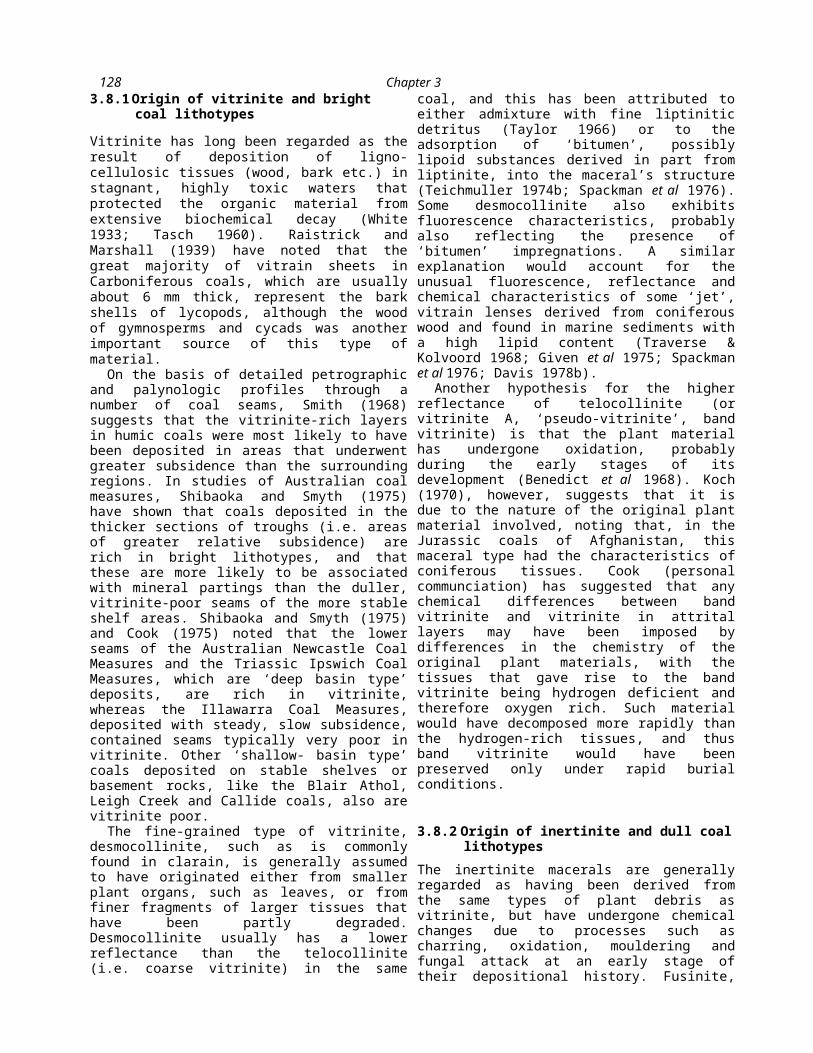
128 Chapter 3
forest fires. Such material, known as ‘pyrofusinite’ (Teichmuller 1950), usually has a high reflectance, appearing yellow or white under oil immersion, and with distinct cell wall margins. Another form, called ‘degradofusinite’, is characterized by indistinct cell walls and a lower, semifusinitic reflectance. This material is thought by Teichmuller to result from dehydration, oxidation and biochemical alteration of plant debris. However, Given (in Given et al 1980) has challenged the possibility that degradofusinite might be the product of biochemical decay. It is -a characteristically abundant constituent of the Permian coals of Gondwanaland. Other fusinite may be of primary origin, derived directly from certain pigmented plant tissues.
Semifiisinite, in general, is regarded as representing ligno-cellulosic plant debris that has suffered a lesser degree of degradation than fusinite. Fragments of both fusinite and semifusinite, often forming discrete inertodetrinite particles, can also be transported some distance from their place of formation, accumulating in quiet, sub-aquatic conditions with other particles such as spores or algae and possibly fine mineral matter.
Sclerotioids (secretion sclerotinite or carbonized resin bodies) are also thought to result from oxidizing conditions in the peat swarnp, although such materials may also be transported from an oxidizing environment nearby. True sclerotinite represents fungal material and is also formed in relatively dry oxygenated peat layers (Stach et al 1975).
_ Micrinite may possibly be formed in two ways. It may represent a by-product of the coalification of liptinite macerals, including bituminite (TeichmiiUer 1974b) and exudatinite (Shibaoka 1978). The suggestion is supported by its frequent association with spo- rinite. Although Teichmuller indicates that micrinite is not normally found in peats or brown coals, others (e.g. Spackman & Barghoorn 1966)
have reported it in such materials. Together with the fact that it frequently occurs as cell fillings in higher rank coal, this suggests that some micrinite may also be formed by the breakdown of cell wall substances.
The origin of macrinite, a relatively rare component of most coals, is not well understood. At least some of it may, however, result from the oxidation (or fusinization) of organic gels formed during peat accumulation.
Because they are made up mainly of fine inertinite debris and have a relative abundance of spore material, the black durains of many humic coals are classically regarded as sub-aquatic ooze deposits, forming in deeper water environments than the bright, vitrain- rich lithotypes (White 1933; Tasch 1960). Hacquebard et al (1967) have generally indicated support for these concepts, interpreting the high telinite (bright coal) contents of some Canadian seams as representing forest moor environments, typical of the central part of a flood plain. The duller intervals of those seams, with relatively high liptinite and mineral contents, are thought to be the product of an open moor environment with a generally higher water table. As an alternative, however, Smith (1968) has suggested that black durains, rich in macrinite and thick-walled crassispores, were formed in a raised, well-drained peat swamp environment. Tenuidurains, in which thin- walled spore types are typically associated with semifiisinite and a high proportion of mineral matter, are interpreted by Stach et al (1975) as representing a horizon of peat oxidation above the water table. Smith (1968) on the other hand interprets them as representing a sub-aquatic ‘incursion phase’ due to flooding of the peat swamp.
The presence of a large amount of

Coal Petrology and Petrographic Analysis
129mineral matterin a coal may also reflect the development of deep-water conditions. However, some workers suggest that such concentrations could also result from sub-aerial ablation of peat, or from excessive peat decay in swamp waters of pH greater than 4.5 (Cecil et al 1979).
3.8.3 Origin of liptinite macerals and sapropelic coals
The organic components that give rise to the various liptinite macerals are described in some detail in Section 3.3.3. Unlike the ligno-cellulosic materials that make up vitrinite, the liptinite precursors are largely resistant to degradation and to the gélification or similar processes generally associated with peat formation. They do, however, exhibit a number of significant changes during coalification or rank advance, and these are discussed more fully in Section 3.6.4.
Cannel coals are believed to be derived from the more resistant components of decayed plants, especially spore remains, that were washed into ponds, lakes and lagoons to accumulate as fine grained, anaerobic bottom muds. Boghead coals or torbanites, on the other hand, are thought to represent circumstances in which clear, aerated surface waters, free of humic matter, allowed algal colonies to flourish (Moore 1968). After death, the remains of these colonies accumulated in euxinic bottom oozes, eventually to become masses of alginite or bituminite.
3.8.4 Temporal and climatic influences on peat accumulation
The coals of different geologic periods
were derived from different plant assemblages, and under differing climatic conditions. These variations have clearly produced some diversity in the petrographic character of coals of different ages.
The plants of the Carboniferous, including such groups as the seed ferns, lycopods and sphenopsids, were commonly prolific producers of thick-walled megaspores and microspores. After the Carboniferous, however, the importance of these plants declined, with many becoming extinct, and the gymnosperms . (which include the seed ferns) became the dominant members of the plant community. These plants produced smaller, thinner-walled palynomorphs than did the Carboniferous plants, and consequently contributed less sporopollenin to the resulting peats than the larger, thicker-walled spores common in the Carboniferous. More importantly the number of megaspores produced was reduced to four, with three of these aborting and then being retained in the megasporangium without developing an exine of liptinitic source material.
The angiosperms have been important members of swamp and marsh communities from the Tertiary to the present. All of these plants retained the megaspore in the ovule with no production of sporopollenin, and with a reduction in total pollen production compared to many gymnosperms. There has therefore been a progressive decrease in the contribution of spores and pollen to the coal-forming swamps from the Carboniferous to the Tertiary, and a change from large, thick-walled palynomorphs to small, thin-walled palynomorphs in the liptinites of the coals produced through time (Waddell et al 1978).
Gondwana coals, formed in the

130 Chapter 3
southern hemisphere mainly during the Permian Period, were derived from the well-known Glossopteris flora. This assemblage was dominated by gymnospermous plants and more restricted in species than the flora which inhabited the Carboniferous forests. The climate for these deposits is believed to have been mainly cool temperate, in contrast to the sub-tropical conditions that probably existed during much of the European Carboniferous.
Some of the characteristics of the Gondwana coals include a much lower sporinite content than is found in the Carboniferous deposits, and a higher inertinite content, made up mainly of semifusinite that formed under oxidizing conditions. Cook (1975) has suggested that a dry climate may have been responsible for the abundance of inertinite-rich coals in the late Permian coal-bearing sequences of Australia.
As stated in Section 3.3.3, thick cuticles may be indicative of a dry, warm climate. Cutinite is rare in Australian Permian coals, but is quite common in the Triassic Ipswich Coal Measures and Jurassic Walloon Coal Measures of Queensland, especially in the Jurassic Rosewood and Darling Downs deposits. Resinite is found in larger quantities in Cretaceous and Tertiary coals than in those of the Carboniferous because of contributions from the resins of conifers in the later-formed materials. Suberinite is a com-ponent of Mesozoic and, particularly, Tertiary coals. True fungal sclerotinite is also a ubiquitous component of Tertiary coals, but is only rare in Carbo-niferous deposits.
3.9 APPLICATIONS OF COAL PETROLOGY
Coal petrology represents one of the main avenues for gaining an
understanding of the origin of coal deposits, and also provides invaluable information in establishing the most appropriate means of using the various coals formed by these processes. Petrologic data, collected on either a megascopic or a microscopic scale, can be used to help solve problems with coal seam correlation, and may be considered in conjunction with other geologic factors to assist in interpreting the location, extent and quality of economic coal resources. Systematic data on coal rank, compiled from features such as vitrinite reflectance, can also be used to establish the tectonic history of the region, and, as a by-product, assess the likelihood that petroleum hydrocarbons might have been generated at some stage of basin development as well.
3.9.1 Seam correlation and other uses of petrographic profiles
Correlations may be drawn from petrologic data wherever a coal seam laterally maintains a unique characteristic, such as a particular vertical sequence of lithotype variation. Hacquebard (1952) has described how the distinct and uniform petrographic composition and seam profile of the Tracy Seam of the Sydney coalfield, Nova Scotia could be used for correlation over distances of at least 12 km, while Smyth (1967) has suggested some correlations between seams of the Newcastle and Illawarra Coal Measures of New South Wales on the basis of their petrographic profiles. Davis (1968) has also noted that two vertically adjacent seams at Moura, Queensland, had such distinct profiles (Fig. 3.20) that, even from megascopic data, it was possible to identify which of the two seams was present in a situation where the stratigraphic sequence had been complicated by faulting.
Coal Petrology and Petrographic Analysis
131In some instances, although the
profile itself may vary, the presence of persistent horizons within the seam can be a considerable aid in correlation. Hacquebard et al (1965) and Cameron (1971) were able to trace individual durain layers in the Harbour seam of Nova Scotia across the width of the Sydney coalfield, a distance of over 32 km, even though the durains themselves changed laterally. A fusain layer in the No. 12 seam of Western Kentucky also extends over an area greater than 130 km2 (Austin & Davis 1979).
Inorganic bands and partings within seams are commonly useful marker horizons as well. The prominent ‘blue band’, a claystone parting of the Herrin (No. 6) seam of the Illinois Basin, has been traced over thousands of square kilometres in Illinois (Willman et al 1975) and western Kentucky, while kaolinite clayrocks or tonsteins (Section 5.3.1) have been employed as markers both within and between individual coalfields. Scheere (1956) has demonstrated the correlation of such horizons from France, through

132 Chapter 3
200 150 100 50 0 200^====^=======i cm . .
Vertical scale
Fig. 3.20 Petrographic profiles of two coal seams from Moura, Bowen Basin, Queensland. (From Davis 1968.) ^ Vitrinite; S semi-inertinite; § inertinite; □ exinite; ■ mineral.
Belgium and Holland and into Germany, covering a distance of about 400 km, and in Queensland, Australia, such horizons have been traced in individual seams (Davis 1972, 1973; Carr & Davis 1973; Beeston 1974). Six carbonaceous shale partings also occur over an area greater than 1500 km2 within the No. 12 seam of western Kentucky referred to above (Austin & Davis 1979).
The vertical succession of lithotypes in seams has been used to study the variation in environmental conditions during coal formation. For example, Hacquebard et al (1967) noted the lack of petrographic variability in coals of limnic sequences in contrast to the greater variability of those in paralic coal measures. The predominant seam profile in Australian coals is one in which the abundance of vitrinite decreases from floor to roof, and this is interpreted by Smyth (1970) as representing a rise in the depositional surface as a result of the development of progressively drier
conditions in the peat swamp.
3.9.2 Applications of reflectance measurements
As indicated in Section 3.6.3, the principal use of reflectance data is as a measure of coal rank. It has long been established that rank increases with depth

Coal Petrology and Petrographic Analysis
133in stratigraphic successions or borehole profiles (a phenomonen described traditionally by ‘Hilts Law’), and this is thought to reflect the effects of rising temperature as the thickness of overburden increases.(a) Reflectance profiles
Reflectance profiles in boreholes have been used to study the tectonic histories of coal-bearing sequences. Dow (1977) has shown the effects of such processes as loss of cover, the development of unconformities, igneous intrusion and faulting on the profiles of organic maturation in sedimentary sequences. The temperature and time required for coalification have been related to the rank or level of metamorphism by authors such as Karweil (1956), Lopatin and Bostick (1973), Hood et al (1975) and Bostick et al (1979). Figure 3.21 is a nomograph, modified after Hood et al (1975), that enables palaeotemperatures to be derived from reflectances, provided the effective heating time can be estimated. The effective heating time is the time during which the sediments were exposed to temperatures within 15 °C of the maximum attained.
In conjunction with the depth of the seams in question, such data can be used to calculate palaeogeothermal gradients and hence allow the
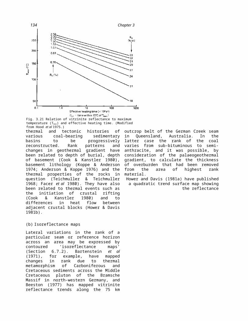
134 Chapter 3
thermal and tectonic histories of various coal-bearing sedimentary basins to be progressively reconstructed. Rank patterns and changes in geothermal gradient have been related to depth of burial, depth of basement (Cook & Kanstler 1980), basement lithology (Koppe & Anderson 1974; Anderson & Koppe 1976) and the thermal properties of the rocks in question (Teichmuller & Teichmuller 1968; Facer et al 1980). They have also been related to thermal events such as the initiation of crustal rifting (Cook & Kanstler 1980) and to differences in heat flow between adjacent crustal blocks (Hower & Davis 1981b).
(b) Isoreflectance maps
Lateral variations in the rank of a particular seam or reference horizon across an area may be expressed by contoured ‘isoreflectance maps’ (Section 6.7.2). Bartenstein et al (1971), for example, have mapped changes in rank due to thermal metamorphism of Carboniferous and Cretaceous sediments across the Middle Cretaceous pluton of the Bramsche Massif in north-western Germany, and Beeston (1977) has mapped vitrinite reflectance trends along the 75 km outcrop belt of the
German Creek seam in Queensland, Australia. In the latter case the rank of the coal varies from sub-bituminous to semi-anthracite, and it was possible, by consideration of the palaeogeothermal gradient, to calculate the thickness of overburden that had been removed from the area of highest rank material.
Hower and Davis (1981a) have published a quadratic trend surface
map showing the reflectance
Fig. 3.21 Relation of vitrinite reflectance to maximum temperature (Tmax) and effective heating time. (Modified from Hood et al 1975.)

Coal Petrology and Petrographic Analysis
135of coals, mainly of Allegheny age, in western Pennsylvania, while Senftle and Davis (1982) have mapped the reflectance of the Lower Kittanning seam in the same area. Facer et al (1980) have produced a third degree trend surface map of the lateral variation in reflectance for seams in the Illawarra Coal Measures of New South Wales. Isoreflectance maps can be used in the planning of mining operations to optimize the supply of coal blend components for metallurgical coke production (Benedict & Thompson 1978).
(c) Interpretation of stress patterns
In another type of study, ¡the orientation of the principal reflectance directions in coal specimens has been used to interpret the directions of tectonic stress in several coalfield areas. Hower and Davis (1981a) and Levine and Davis (1984), for example, found that the maximum retlectance of tightly folded biaxial coals of low volatile bituminous and anthracitic rank in Pennsylvania was oriented sub-parallel to the fold axes, while Stone and Cook (1979) observed that the biaxial reflectance anisotropy of samples from the proximity of normal faults in the Southern Coalfield of New South Wales could be related to probable local stress patterns associated with the faulting. Studies of this type can be applied to a number of problems with the stability of underground mining operations, such as those discussed in Section 7.6.
Although reflectance anisotropy generally increases with increasing rank (Section 3.6.2), values of bireflectance obtained from vitrinite in the Bowen Basin of Queensland show fairly uniform values
136 Chapter 3
throughout much of the rank range in that area (Davis 1971). Hower and Davis (1981b) found that another index of anisotropy,
R ~~ Rmax vrand
R~‘
remained more or less constant along traverses from west to east in western Pennsylvania, whereas vitrinite reflectance generally showed marked increases. They interpreted this to indicate that the past depth of burial was also uniform across the area.
(d) Generation of petroleum hydrocarbons
In 1915, White observed that the presence, amount and type of petroleum in sedimentary rocks could be related to the rank of any associated coals in the sequence. Rank at that time was defined solely by chemical parameters, and the resulting theory has therefore become known as the ‘carbon ratio theory*. It has been investigated in many parts of the world, and several of the findings of these studies have been compiled by Bostick and Damberger (1971).
Briefly, the theory suggests that a certain level of maturation (i.e. rank) is necessary for organic matter in the source rocks to generate hydrocarbon liquids. As the rank increases, however, the liquids become lighter and ultimately only natural gas is produced under the prevailing temperature conditions. Figure 3.22 gives a summary of correlations between coal rank (vitrinite reflectance) and the zones of petroleum generation, and also shows the ‘death line5, where the rank becomes too high for liquid hydrocarbons to form.
As well as the rank, however, the composition of the organic matter (kerogen) in the sediments is also important in determining the type and amount of petroleum that might have been generated. Kerogen derived from algae and marine organic matter
will generate oil and gas in relatively large quantities, whereas humic kerogen, mostly derived from terrestrial plants, is thought by some authors to generate only minor amounts of gases (Dow 1977; Tissot & Welte 1978). In addition, the source rocks must contain sufficient kerogen (at least about 0.5% organic matter) to provide for the possible accumulation of petroleum in the first place.
3.9.3 The petrographic prediction of coke properties
In the 1960s, the work of Ammosov et al (1957) and Schapiro et al (1961) gave a new stimulus to the
_______^1__ J ..
Coal Petrology and Petrographic Analysis
137practice of coal petrology through the development of procedures whereby the quantitative strength characteristics of metallurgical cokes from single or blended coals could be predicted. Such procedures are described more fully in Section 4.3.6. Although these empirical methods have generally been successful, some of the concepts incorporated in the original mathematical models are not accepted universally, and some care should be taken in their use.
Depending on the rank of the coal, the models are based on the assumption that vitrinite, liptinite and possibly some of the semifusinite react in the process of coke formation and bind the other inertinite components and mineral matter into a porous fused solid. The model devised by Schapiro et al (1961) predicts coke strength on the basis of the relative abundance of the reactive and non-reactive constituents, and also on the abundance of vitrinite in reflectance classes that correspond to the vitrinoid types (V-types) discussed in Section 3.7.6. However, the model makes an arbitrary subdivision of the semifusinite, regarding one-third of that material as reactive and two-thirds as non-reactive, a procedure that is not in accord with observations of Taylor et al (1967), which suggest that this maceral does not become plastic during coking. It is also not always desirable to treat liptinite in the coal as a reactive maceral in the same sense as the viLimiic, since me upimiLe is mosiiy uevoiaimzeu in the carbonization process and contributes little to the final product. The breakdown of vitrinite reflectance data into V-types, although it represents a practical way of dealing with the coking properties of the vitri- nites of different rank from the various coals in a blend, also makes arbitrary and unproved distinctions between and within the vitrinite types that might be present in a single coal.
Other methods of coke strength prediction include those of Benedict et al (1968), which allows for the poorer caking characteristics of ‘pseudovitrinite5 compared to ‘reactive5 vitrinite, and Mackowsky and Simonis (1969), which incorporates parameters of coking conditions into the prediction. Gray et al (1979) have described how results using the method of Schapiro et al (1961) may be modified to allow for the coking conditions.
Petrographic methods also have been established to predict the pressures and expansion or contraction developed during carbonization, and the reactivities of cokes (Benedict & Thompson 1976; Thompson & Benedict 1976; Gray Goscinsky & Shoenberger 1979).
3.9.4 The microscopic detection of coal oxidation
The oxidation of coals, caused by weathering in

138 Chapter 3
Gray et al (1976) have described a technique for staining coals with an alkaline solution of the red stain Safranin 0. Oxidized particles appear green under the microscope. The test, as described, is not reliable for coals higher in rank than high volatile bituminous; however, a modification which overcomes this limitation has recently been developed (Gray, personal communication).
* The descriptions of the microlithotypes refer to their analysis by the 20 point ocular method (Section 3.7.5).
Fig. 3.22 Correlation of coal rank and vitrinite reflectance with the zones of petroleum generation and destruction. The relative importance of the zone of petroleum generation depends upon the composition of the original kerogen. (Modified from