Embed Size (px)
Citation preview
Coating Deposition
672
Deposition of Oxides and Oxinitrid Thin Films for Medical Grafts by Method of Pulsed Magnetron Sputtering
V.F. Pichugin, V.P. Yanovskii*, N.S. Morosova, and I.М. Yermolovich
Tomsk Polytechnic University, 30, Lenin ave., Tomsk, 634050, Russia *Institute of Strength Physics and Material Sciences SB RAS, Akademichesky ave., Tomsk, 634055, Russia
Abstract – Oxides and oxinitrid thin films were synthesized by pulsed magnetron reactive sputte- ring deposition technique. Optical emission spec-troscopy was used to characterize magnetron plas- ma. Experiments were carried out at pressure in the range 0.1–0.5 Pa in either pure oxygen or nitro-gen and in the mixtures with Ar. The structure and composition of the Ti–O and Ti–O–N films were investigated using X-ray diffraction (XRD). Mor-phology of the surface was analyzed by SEM tech-nique. Nano-hardness, Young’s modulus, elastic recovery, friction constant and electric properties of the films were investigated also.
1. Introduction
The problem of medical implants biocompatibility is one of the actual problems of medical materials sci-ence. About 10% of cardiovascular surgery patients in the first year suffer from restenosis in stent (RiS) after implantation in some cases as a cause of thrombosis. Thus the problem of material biocompatibility is very actual for cardiovascular surgery. Creating of hemo-compatible coatings on the surface is resource for solving this problem. Ti–O/Ti–N films are one of the perspective types of the coronary stents coatings. The film must possess the following general properties: to be biocompatible, continuitibles, without crack and defects with a thickness no more then 1 µм. Also the films must have high density, high adhesion and me-chanical characteristics. Ion-plasma method (in par-ticular the method of the magnetron sputtering deposi-tion) is more effective method for this sort of coatings.
2. Experimental set up
Pulsed dc magnetron reactive sputtering of dielectrics provides a deposition process without arcing. The deposition process was carried out with pulsing fre-quencies 60 kHz and duty cycles in the range 50–90%. The operating conditions were optimized empirically and are critically dependent on the properties of the pulsed plasma in the immediate vicinity of the magne-tron. The method of time-resolved optical emission spectroscopy used to characterize the pulsed magne-tron plasma. The pulsed dc sputtering of Ti target and the reactive sputtering of their oxides was used in our experiments. Our experiments were carried out at total pressures in the range 0.1–0.6 Pa in either pure O2 (“oxide” mode) or in Ar–O2 mixtures with mixing ratios from 1 : 1 to 1 : 7.
Block diagram of the installation is represented in Fig. 1.
Fig. 1. Block-diagram of installation
It includes vacuum chamber with magnetron, high-vacuum system on basis of the turbomolecular pump, pulsed supply source of magnetron, three-channel gas feed system, control system of installation and per-sonal computer. The magnetron source and table for samples with rotary drive are situated inside the chamber. The source of the magnetron supply PS MS1 provides constant or modulated magnetron supply. The source works in the regime of the current stabili-zation or in the regime of the power stabilization. Disk magnetron sputtering system (MSS) with diameter 200 mm is creates in the form of monoblock includes box-anode and cathode assembly inside. Magnetic system creates magnetic field with intensity equals 0.25 sharply decreased to the anodes.
The contemporary conception of gas discharge in magnetoisolated systems is reviewed in the [1]. The main principle is presence of three quasiautonomous regions: narrow sheath of cathode voltage drop (cath-ode dark sheath), plasma region with electrons cap-tured by magnetic field where the main generation of charge particles occurs and wide enough anode region (anode dark sheath) where charge particles accelerate freely to the anode.
Stainless steel was used as substrates. The samples were ultrasonically cleaned three times in de-ionized water for 15 min and then air dried.
The surface morphology and topography of the Ti–O and Ti–O–N films was studied by scanning electron microscopy (SEM) with an ESEM Quanta 400 FEG instrument from FEI, equipped with energy-dispersive X-ray analysis (EDX; EDS analysis system Genesis 4000, SUTW-Si(Li) detector) and atomic force mi-
Poster Session
673
croscopy (AFM, Autoprobe CP). X-ray diffractometry was carried out with a Siemens D 500 diffractometer operating with CuKα-radiation (λ = 1.5406 Å) at 40 kV and 30 mA in Bragg–Brentano mode. The semicon-ducting behavior of the films was investigated using an electroconductivity measurement.
The chemical composition of the plasma was in-vestigated by optical emission spectroscopy. Plasma emission withdraws from vacuum chamber by lens tube with inlet of 2 mm on the end directed to the dis-charge. A spectrophotometer Avaspec 3648 was used in our experiments. This optical device is built at clas-sical scheme of Cherny–Terner. It allow to observe the spectra of plasma optical emission in region 200–1100 nm with resolution 1.5 nm and writing time of spectrum 5 ms – 10 s. Identification of the plasma emission lines was performed according to Ref. [2]. Software allows detecting the intensity of the selected lines versus time and observing the dynamics of plasma deposition processes.
Inlet of chemically active gas (O2, N2) in the dis-charge leads to the growth of the discharge resistance. This indicates that plasma electrons begin to consume the energy on the supplementary elastic and inelastic interaction with molecule of oxygen and nitrogen. That leads to the appreciable increasing of discharge voltage and decreasing of discharge current under same conditions. The processes of binary compounds (TiN, TiO2) formation and cathode “poisoning” by the molecules of oxygen and nitrogen leads to the increas-ing of concentration of reacting gas and increasing of discharge voltage and decreasing of discharge current in addition.
Let us estimate the role of sputtered atoms of Ti in the processes of formation of plasma in discharge. Atoms of Ti come into being on the cathode surface with effective area S at the expense of cathode sputter-ing with coefficient k ≈ 0.5 [3] by ions of working gas with density Ji and leave the cylinder V at transit time τ. Then
Ti1 ,=τi
nkJ S Ve
where nTi is the mean concentration of Ti atoms. Tak-ing into account that current on the cathode is due to ions one can consider JiS = Id. A transit time τ of Ti atoms is determined by distance R to the specimen at low pressure. The energy of Ti atom is about 5 eV. Lifetime is
Ti
,τ =υR Ti
TiTi
2 ,υ =eTM
where Tiυ is average velocity of Ti atoms; TTi and MTi are their average energy and mass, respectively. So, the concentration of sputtered Ti atoms can reach the value
11 3TiTi
Ti2 10 cm .
2−= ≅ ⋅dkI R Mn
eV eT
Concentration of orifice gas (Ar or O2) at low pressure is about 6 ⋅ 1013 cm–3, and the concentration of reacting gas is one order less. So, the concentration of Ti atoms is minor and it is possible to suppose that Ti atoms don’t play defining role in plasma formation.
3. Optical characteristics
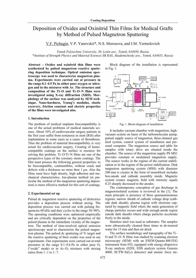
Spectra of optical emission are obtained for different operating mode. Characteristic spectrum of emission of plasma with working gas 0.1Ar + 3O2 is repre-sented in Fig. 2.
Fig. 2. Spectrum of emission of plasma (0.1Ar + 3O2)
The lines at 336–520 nm are attributed to Ti. Group of the peak in the region 600 – 1000 nm with domi-nant line at 811 nm are belong to Ar.
Spectrum of emission of plasma of Ti spattering in medium of pure oxygen (Fig. 3) is characteristic of presence of three groups of lines of oxygen with dominant line at 778 nm, which is in good agreement with data [3]. The lines of Ti are very weak.
Fig. 3. Spectrum of emission of plasma (O2)
Four groups of lines at (520–650 nm) which can be attributed to TiO molecule [2] appears at the same time. These groups are presented in emission spectra always at different oxygen concentrations. Absence of the titanium lines in the spectra indicates that syn-thesis of TiO+ molecules takes place in the plasma of magnetron discharge. Taking into account that plasma has positive potential relative any object which is in contact with it the growth of the film is conditioned by flux of the TiO+ molecular ions to the surface of con-densation. Spectrum of emission of plasma in the O2 + N2 mix is shown in Fig. 4.
Wavelength, nm
Inte
nsity
, a. u
.
Wavelength, nm
Inte
nsity
, a. u
.
Coating Deposition
674
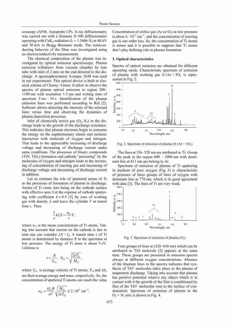
Fig. 4. Spectrum of emission of plasma (1O2 + 1N2)
Three groups of lines at 650–800 nm with identical type of peaks in the group appear in the spectra. This set of spectral lines in the group belongs to the Ti + + N + O complexes probably. There are also the lines of TiO and TiN in the spectra. These lines are similar to those of the plasma of single-component gas. In spite of great number of nitrogen lines in the discharge in the condition of oxynitride deposition there are only five lines of molecular nitrogen. Lines identification demonstrates absence of emission of ions. For obser-vation of the processes in plasma the lines of molecu-lar nitrogen at 357.69 nm, titanium at 468.2 nm and argon at 420.07 and 696.54 nm were chosen. Short range of optimal conditions of binary compound TiO and TiN synthesis is found in the work. This range corresponds to the decrease of intensity of lines of titanium when oxygen or nitrogen puffing in the dis-charge chamber.
The SEM micrograph of surface of sample is shown in Fig. 5.
Fig. 5. SEM-patterns of TiO2 coating morphology
The surface of magnetron deposited coatings is homogeneous, dense, and no cracks were observed (Fig. 5). The results show that deposited coating has character of nanocomposite with two-phase amor- phous-crystalline structure with high part of interphase boundary.
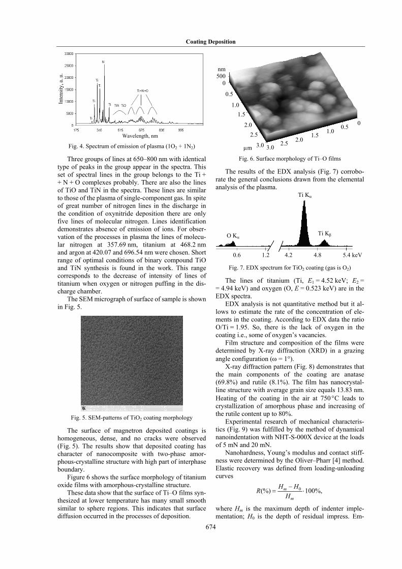
Figure 6 shows the surface morphology of titanium oxide films with amorphous-crystalline structure.
These data show that the surface of Ti–O films syn-thesized at lower temperature has many small smooth similar to sphere regions. This indicates that surface diffusion occurred in the processes of deposition.
Fig. 6. Surface morphology of Ti–O films
The results of the EDX analysis (Fig. 7) corrobo-rate the general conclusions drawn from the elemental analysis of the plasma.
Fig. 7. EDX spectrum for TiO2 coating (gas is O2)
The lines of titanium (Ti, E1 = 4.52 keV; E2 = = 4.94 keV) and oxygen (O, E = 0.523 keV) are in the EDX spectra.
EDX analysis is not quantitative method but it al-lows to estimate the rate of the concentration of ele-ments in the coating. According to EDX data the ratio O/Ti = 1.95. So, there is the lack of oxygen in the coating i.e., some of oxygen’s vacancies.
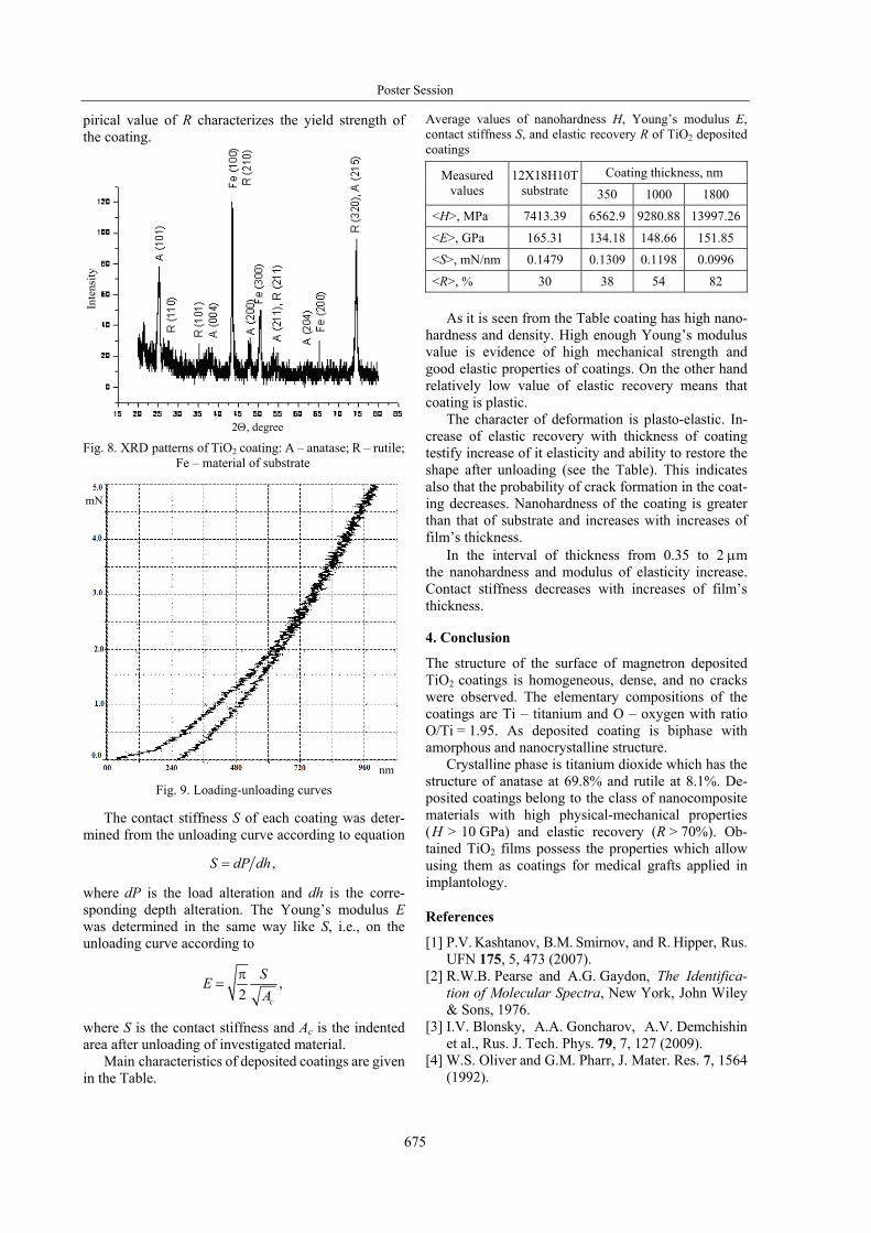
Film structure and composition of the films were determined by X-ray diffraction (XRD) in a grazing angle configuration (ω = 1°).
X-ray diffraction pattern (Fig. 8) demonstrates that the main components of the coating are anatase (69.8%) and rutile (8.1%). The film has nanocrystal-line structure with average grain size equals 13.83 nm. Heating of the coating in the air at 750 °С leads to crystallization of amorphous phase and increasing of the rutile content up to 80%.
Experimental research of mechanical characteris-tics (Fig. 9) was fulfilled by the method of dynamical nanoindentation with NHT-S-000X device at the loads of 5 mN and 20 mN.
Nanohardness, Young’s modulus and contact stiff-ness were determined by the Oliver–Pharr [4] method. Elastic recovery was defined from loading-unloading curves
0–(%) 100%,= ⋅m
m
H HRH
where Hm is the maximum depth of indenter imple-mentation; Н0 is the depth of residual impress. Em-
Wavelength, nm
Inte
nsity
, a. u
.
nm500
0
0.5
1.01.5
2.5
μm
0.5 0
1.5 2.5
2.0
3.0 3.02.0
1.0
0.6 1.2 4.2 4.8 5.4 keV
O Kα
Ti Kα
Ti Kβ
Poster Session
675
pirical value of R characterizes the yield strength of the coating.
Fig. 8. XRD patterns of TiO2 coating: A – anatase; R – rutile; Fe – material of substrate
Fig. 9. Loading-unloading curves
The contact stiffness S of each coating was deter- mined from the unloading curve according to equation
,=S dP dh
where dP is the load alteration and dh is the corre- sponding depth alteration. The Young’s modulus E was determined in the same way like S, i.e., on the unloading curve according to
,2π
=c
SEA
where S is the contact stiffness and Ac is the indented area after unloading of investigated material.
Main characteristics of deposited coatings are given in the Table.
Average values of nanohardness H, Young’s modulus E, contact stiffness S, and elastic recovery R of TiO2 deposited coatings
Coating thickness, nm Measured values
12Х18Н10Тsubstrate 350 1000 1800
<H>, MPa 7413.39 6562.9 9280.88 13997.26
<E>, GPa 165.31 134.18 148.66 151.85
<S>, mN/nm 0.1479 0.1309 0.1198 0.0996
<R>, % 30 38 54 82 As it is seen from the Table coating has high nano-
hardness and density. High enough Young’s modulus value is evidence of high mechanical strength and good elastic properties of coatings. On the other hand relatively low value of elastic recovery means that coating is plastic.
The character of deformation is plasto-elastic. In-crease of elastic recovery with thickness of coating testify increase of it elasticity and ability to restore the shape after unloading (see the Table). This indicates also that the probability of crack formation in the coat-ing decreases. Nanohardness of the coating is greater than that of substrate and increases with increases of film’s thickness.
In the interval of thickness from 0.35 to 2 μm the nanohardness and modulus of elasticity increase. Contact stiffness decreases with increases of film’s thickness.
4. Conclusion
The structure of the surface of magnetron deposited TiO2 coatings is homogeneous, dense, and no cracks were observed. The elementary compositions of the coatings are Ti – titanium and O – oxygen with ratio O/Ti = 1.95. As deposited coating is biphase with amorphous and nanocrystalline structure.
Crystalline phase is titanium dioxide which has the structure of anatase at 69.8% and rutile at 8.1%. De-posited coatings belong to the class of nanocomposite materials with high physical-mechanical properties (Н > 10 GPa) and elastic recovery (R > 70%). Ob-tained TiO2 films possess the properties which allow using them as coatings for medical grafts applied in implantology.
References
[1] P.V. Kashtanov, B.M. Smirnov, and R. Hipper, Rus. UFN 175, 5, 473 (2007).
[2] R.W.B. Pearse and A.G. Gaydon, The Identifica- tion of Molecular Spectra, New York, John Wiley & Sons, 1976.
[3] I.V. Blonsky, A.A. Goncharov, A.V. Demchishin et al., Rus. J. Tech. Phys. 79, 7, 127 (2009).
[4] W.S. Oliver and G.M. Pharr, J. Mater. Res. 7, 1564 (1992).
2Θ, degree
Inte
nsity
mN
nm


![Introduction - Shodhgangashodhganga.inflibnet.ac.in/bitstream/10603/4037/7/07_chapter 1.pdf · B) Vacuum arc vapour deposition [9]: In arc vapour deposition, the material deposition](https://img.pdfslide.net/doc/110x75/5e282f350175b03995481f03/introduction-1pdf-b-vacuum-arc-vapour-deposition-9-in-arc-vapour-deposition.jpg)