Embed Size (px)
Citation preview


COATINGS TRIBOLOGY

TRIBOLOGY AND INTERFACE ENGINEERING SERIES
Editor
Brian Briscoe (UK)
Vol. 27 Dissipative Processes in Tribology (Dowson et al., Editors)
Vol. 28 Coatings Tribology – Properties, Techniques and Applications in Surface
Engineering (Holmberg and Matthews)
Vol. 29 Friction Surface Phenomena (Shpenkov)
Vol. 30 Lubricants and Lubrication (Dowson et al., Editors)
Vol. 31 The Third Body Concept: Interpretation of Tribological Phenomena (Dowson et al., Editors)
Vol. 32 Elastohydrodynamics – ’96: Fundamentals and Applications in Lubrication
and Traction (Dowson et al., Editors)
Vol. 33 Hydrodynamic Lubrication – Bearings and Thrust Bearings (Frene et al.)
Vol. 34 Tribology for Energy Conservation (Dowson et al., Editors)
Vol. 35 Molybdenum Disulphide Lubrication (Lansdown)
Vol. 36 Lubrication at the Frontier – The Role of the Interface and Surface Layers
in the Thin Film and Boundary Regime (Dowson et al., Editors)
Vol. 37 Multilevel Methods in Lubrication (Venner and Lubrecht)
Vol. 38 Thinning Films and Tribological Interfaces (Dowson et al., Editors)
Vol. 39 Tribological Research: From Model Experiment to Industrial Problem
(Dalmaz et al., Editors)
Vol. 40 Boundary and Mixed Lubrication: Science and Applications (Dowson et al., Editors)
Vol. 41 Tribological Research and Design for Engineering Systems (Dowson et al., Editors)
Vol. 42 Lubricated Wear – Science and Technology (Sethuramiah)
Vol. 43 Transient Processes in Tribology (Lubrecht, Editor)
Vol. 44 Experimental Methods in Tribology (Stachowiak and Batchelor)
Vol. 45 Tribochemistry of Lubricating Oils (Pawlak)
Vol. 46 An Intelligent System For Tribological Design In Engines (Zhang and Gui)
Vol. 47 Tribology of Elastomers (Si-Wei Zhang)
Vol. 48 Life Cycle Tribology (Dowson et al., Editors)
Vol. 49 Tribology in Electrical Environments (Briscoe, Editor)
Vol. 50 Tribology & Biophysics of Artificial Joints (Pinchuk)
Vol. 52 Tribology of Metal Cutting (Astakhov)
Vol. 53 Acoustic Emission in Friction (Baranov et al.)
Vol. 54 High Pressure Rheology for Quantitative Elastohydrodynamics (Bair)
Vol. 55 Tribology of Polymeric Nanocomposites: Friction and Wear of Bulk Materials and Coatings
(Friedrich and Schlarb)
Aims & Scope
The Tribology Book Series is well established as a major and seminal archival source for definitive books
on the subject of classical tribology. The scope of the Series has been widened to include other facets of
the now-recognised and expanding topic of Interface Engineering.
The expanded content will now include:
� colloid and multiphase systems; � rheology; � colloids; � tribology and erosion; � processing systems;
� machining; � interfaces and adhesion; as well as the classical tribology content which will continue to
include � friction; contact damage; � lubrication; and � wear at all length scales.
Advisory Board
M.J. Adams (U.K.)
J.H. Beynon (U.K.)
D.V. Boger (Australia)
P. Cann (U.K.)
K. Friedrich (Germany)
I.M. Hutchings (U.K.)
J. Israelachvili (U.S.A.)
S. Jahanmir (U.S.A.)
A.A. Lubrecht (France)
I.L. Singer (U.S.A.)
G.W. Stachowiak (Australia)
TRIBOLOGY AND INTERFACE ENGINEERING SERIES, 56EDITOR: B.J. BRISCOE
COATINGS TRIBOLOGY
Properties, Mechanisms, Techniques
and Applications in Surface
Engineering
Second Edition
Kenneth Holmberg
VTT – Technical Research Centre of Finland
Allan Matthews
The University of Sheffield, UK
Amsterdam � Boston � Heidelberg � London � New York � OxfordParis � San Diego � San Francisco � Singapore � Sydney � Tokyo
Elsevier
Radarweg 29, PO Box 211, 1000 AE Amsterdam, The Netherlands
The Boulevard, Langford Lane, Kidlington, Oxford OX5 IGB, UK
First edition 1994
Copyright � 2009 Elsevier B.V. All rights reserved
No part of this publication may be reproduced, stored in a retrieval system or transmitted in any form or by any means
electronic, mechanical, photocopying, recording or otherwise without the prior written permission of the publisher
Permissions may be sought directly from Elsevier’s Science & Technology Rights Department in Oxford, UK: phone
(+44) (0) 1865 843830; fax(+44) (0) 1865 853333; email: [email protected]. Alternatively you can submit your
request online by visiting the Elsevier web site at http://elsevier.com/locate/permissions, and selecting obtaining
permission to use Elsevier material
Notice
No responsibility is assumed by the publisher for any injury and/or damage to persons or property as a matter of products
liability, negligence or otherwise, or from any use or operation of any methods, products, instructions or ideas contained
in the material herein. Because of rapid advances in the medical sciences, in particular, independent verification of
diagnoses and drug dosages should be made
British Library Cataloguing in Publication Data
Holmberg, Kenneth.
Coatings tribology: contact mechanisms, deposition
techniques and application. – 2nd ed. – (Tribology and
interface engineering series; v. 56)
1. Tribology. 2. Coatings.
I. Title II. Series III. Matthews, A. (Allan)
621.809-dc22
Library of Congress Cataloging-in-Publication Data
A catalog record for this book is available from the Library of Congress
Library of Congress Control Number: 2009920710
ISBN: 978-0-444-52750-9
ISSN: 1572-3364
For information on all Elsevier publications
visit our web site at books.elsevier.com
Printed and bound in Great Britain
09 10 11 12 13 10 9 8 7 6 5 4 3 2 1

ToVille, Maya and Hanna
andDave and Lynda

This page intentionally left blank

CONTENTS
PREFACE xi
ACKNOWLEDGEMENTS xii
NOTATION xiii
1 Introduction 1
2 Deposition processes and coating structures 72.1 Introduction 72.2 Gaseous state processes 8
2.2.1 General 82.2.2 Chemical vapour deposition 92.2.3 Physical vapour deposition 122.2.4 Ion and laser beam-assisted deposition and surface treatment 21
2.3 Solution state processes 232.3.1 Chemical solution deposition 242.3.2 Electrochemical deposition 252.3.3 Sol-gel processing 262.3.4 Plasma electrolysis 27
2.4 Molten and semi-molten state processes 272.4.1 Laser surface treatments 282.4.2 Thermal spraying 282.4.3 Welding 282.4.4 Other developments 29
2.5 Surface hardening treatments 302.6 Process effects on coating structures 31
2.6.1 Morphological growth structures 312.6.2 Composite structures 33
vii

3 Tribology of coatings 413.1 Friction, wear and lubrication 41
3.1.1 General 413.1.2 Surface characteristics 413.1.3 Friction 443.1.4 Wear 533.1.5 Lubrication 64
3.2 Surface stresses and response to loading 753.2.1 Response of materials to loading 753.2.2 Material parameters E, sy, H, G and Kc 773.2.3 Analytical solutions of contact stresses and deformations at surfaces
of solid materials 783.2.4 Criteria for plastic yield 813.2.5 Criteria for material fracture 823.2.6 Analytical solutions of stresses and deformations in normally
loaded coated surfaces 833.2.7 Analytical solutions of stresses and deformations in normally and
tangentially loaded coated surfaces 873.2.8 Finite element method modelling and simulation of stresses and deformations 923.2.9 Influence of surface roughness 1043.2.10 Residual stresses 1083.2.11 Influence of interface cracks 117
3.3 Surface fracture and wear products 1173.3.1 Crack nucleation 1183.3.2 Surface crack propagation 1193.3.3 Crack growth in coated surfaces 1213.3.4 Toughness and fracture toughness in coated surfaces 1273.3.5 Crack patterns 1283.3.6 Coating to substrate adhesion 1303.3.7 Debris generation and particle agglomeration 1333.3.8 Transfer layers 1353.3.9 Tribochemical reaction layers 137
3.4 Tribological mechanisms in coated surfaces 1393.4.1 Scales in tribology 1393.4.2 Macromechanical friction mechanisms 1423.4.3 Macromechanical wear mechanisms 1533.4.4 Micromechanical tribological mechanisms 1623.4.5 Tribochemical mechanisms 1693.4.6 Nanophysical tribological mechanisms 1723.4.7 Lubricated coated contacts 175
4 Tribological properties of coatings 1854.1 General 1854.2 Soft coatings 186
4.2.1 Polymer coatings 1864.2.2 Soft metal coatings 197
4.3 Lamellar coatings 2114.3.1 Properties of molybdenum disulphide 2114.3.2 Burnished and bonded molybdenum disulphide coatings 2124.3.3 PVD deposited molybdenum disulphide coatings 214
viii Contents

4.4 Hard coatings 2254.4.1 Titanium nitride coatings 2264.4.2 Other nitride coatings 2364.4.3 Carbide coatings 2434.4.4 Oxide coatings 2464.4.5 Boride coatings 248
4.5 Carbon and carbon-based coatings 2494.5.1 Diamond as a coating material 2494.5.2 Diamond coatings 2534.5.3 Diamond-like carbon coatings 266
4.6 Combined coatings 2994.6.1 Multicomponent coatings 2994.6.2 Nanocomposite coatings 3034.6.3 Multilayer coatings 3044.6.4 Duplex treatments 3114.6.5 Adaptive coatings 316
5 Coating characterization and evaluation 3195.1 The requirements 3195.2 Coating characteristics 319
5.2.1 The surface 3195.2.2 Thickness 3205.2.3 Adhesion 3205.2.4 Morphology 3215.2.5 Composition 3225.2.6 Wettability 3225.2.7 Residual stress 323
5.3 Property characterization and evaluation 3235.3.1 Roughness 3245.3.2 Thickness 3245.3.3 Mechanical evaluation 3265.3.4 Physico-chemical evaluation 3425.3.5 Tribological evaluation 3475.3.6 Accelerated testing 3555.3.7 Industrial field testing 3595.3.8 Standardization 360
6 Coating selection 3636.1 Problems of selection 3636.2 Traditional approaches 3656.3 A methodology for coating selection 3676.4 Selection rules 3716.5 Design guidelines 3776.6 Expert systems 3796.7 Closing knowledge gaps 382
7 Applications 3837.1 General 3837.2 Sliding bearings 384
7.2.1 Description of the application 3847.2.2 Improvements by surface coatings 385
ixContents

7.3 Rolling contact bearings 3877.3.1 Description of the application 3877.3.2 Improvements by surface coatings 388
7.4 Gears 3937.4.1 Description of the application 3937.4.2 Improvements by surface coatings 394
7.5 Tools for cutting 3977.5.1 Description of the application 3977.5.2 Tool wear 3997.5.3 Improvements by surface coatings 4037.5.4 Cutting test results 405
7.6 Tools for forming 4137.6.1 Description of the application 4137.6.2 Improvements by surface coatings 413
7.7 Erosion and scratch resistant surfaces 4147.7.1 Description of the application 4147.7.2 Improvements by surface coatings 415
7.8 Oscillating contacts 4177.8.1 Description of the application 4177.8.2 Improvements by surface coatings 419
7.9 Magnetic recording devices 4227.9.1 Description of the application 4227.9.2 Improvements by surface coatings 423
7.10 Microcomponents 4277.10.1 Description of the application 4277.10.2 Improvements by surface coatings 428
7.11 Biomedical applications 4317.11.1 Description of the application 4317.11.2 Improvements by surface coatings 433
7.12 Future issues 435
APPENDIX A 441
APPENDIX B 473
REFERENCES 477
SUBJECT INDEX 549
x Contents

PREFACE
This book gives a comprehensive description of thin surface coatings, their behaviour and potentialuses in tribological applications. The deposition techniques, tribological mechanisms, properties ofcoatings, characterization, evaluation and selection methodology in addition to application examplesare described and discussed. One aim of the book has been to bring together, systematically in a singlevolume, the state-of-the-art knowledge on tribological coatings.
The book is the result of very fruitful research cooperation between the tribology research group atthe VTT Technical Research Centre of Finland in Helsinki and the Surface Engineering researchgroup at the University of Sheffield in the UK. It brings together accumulated knowledge both oncoating processes and on the tribology of coatings.
The authors published the first edition of the book in 1994. The contents in this second edition arethoroughly revised and expanded by more than 50%. Completely new sections have been writtenrelated to deposition of composite and nanostructured coatings, nanotribological contact mechanisms,modelling and simulation of stresses in coated surfaces, fracture mechanics analysis, wear productgeneration, lubricated contact mechanisms, diamond-like carbon and molybdenum disulphide coat-ings, coating selection and application examples. In the earlier text, we tried to take into account themost important published works at that time which covered over 1500 in all and we cited over 800 ofthese. Since then, the field has seen a remarkable growth in published output, and in the present bookmore than 3000 publications were scrutinized, of which about 1700 are cited herein.
As in the earlier book, we have tried to present the contents in a logical, easily assimilated, manner.We have retained the systematic structure of the earlier book, which has remained appropriate androbust, despite the many developments over the ensuing years.
Kenneth HolmbergAllan Matthews
Helsinki and SheffieldSeptember 2008
xi
ACKNOWLEDGEMENTS
A great number of people, including colleagues, friends and family, have through the years supportedand encouraged the authors with their work in the field of coatings and tribology. We are most gratefulto all of them and express our sincere thanks.
The authors also extend their thanks to Mr Erkki Makkonen for meticulous preparation of theillustrations.
The financial support of the Swedish Academy of Engineering Sciences in Finland and the VTTTechnical Research Centre of Finland is gratefully acknowledged.
xii

NOTATION
Symbols
a length of crack or deformation, or afterA area, e.g. contact area or projected area of indentation
Aa contact area contributed by deformed asperitiesAc load support area of the coatingAd debris contact areaAs load support area of the substrateb half contact length or beforec constant or crack lengthC contentd diameter or indentation diagonal length or crack depthE Young’s modulus of elasticity or elastic modulus
E0 reduced modulus of elasticity, 1/E0 ¼ 0.5((1 � v12)/E1 + (1 � v2
2)/E2)F friction forceG material parameter in elastohydrodynamic lubrication, G ¼ a $ E’, or toughnessG strain–energy release rateH hardness
H0 film thickness parameter, H0 ¼ h/R0
h film thickness or indentation displacementk constantK wear rate, K ¼ V/w $ s, or fracture toughness or stress intensity factor
K0 coefficient of wear, K0 ¼ V $ H/w $ sl length of contact
Lc critical loadm indentation size effect (ISE) indexM torquen number of cyclesp pressurer radiusR radius
xiii

R0 radius of conformity, 1/R0 ¼ (1/R1) + (1/R2)Ra centreline average value (CLA or Ra) for the roughness of the surfaceRc Rockwell hardness (c-scale)
RH relative humidityRmax maximum height of irregularities
Rt peak-to-valley height value for the roughness of the surfaceRz ten points height value for the roughness of the surface
s distanceS shear strength or slope of unloading curvet0 dummy variableT temperature or transition zoneu velocity
u0 displacement in x-directionU speed parameter, U ¼ (ho $ u0)/(E0 $ R0) or elastic energy storedv velocity
v0 displacement in y-directionV volume of worn or deformed materialw normal load
w0 load per unit lengthW load parameter, W ¼ w/(E0 $ R0 $ l), or workx distance in x-direction or length of distancey distance in y-direction or length of distanceY yield stress or correction factorz distance in z-directionZ crack shape factor
Greek symbols
a pressure exponent of viscosity or coefficient of thermal expansion or empiricalcontact
b percentage of asperity contact area under compressiong Boussinesq function or surface energyG deviator stress or unit area3 strain or indenter geometry constantz standard deviation of asperity height distributionr crack spacingh absolute dynamic viscosityQ anglec empirical interface parameterl specific film thickness, l ¼ hmin/R0am coefficient of friction, m ¼ F/wv Poisson’s ratios stress or strength in tensions stress or strength in shear
sa shear strength within asperity adhesion area
Subscripts
a adhesion or asperity or abrasivec coating or critical or contact
xiv Notation

comp composited deformation or debrise effectivef film or final
fat fatigueH hydrogen
Hz Hertziani counter, i ¼ 1, 2, ., N
int interfaceI interfacej junctionk Knoop
m melting or hydrostaticmax maximummin minimum
o ambientp ploughing or peakr radial or rough or reduced or residual
res residuals substrate
th thermalu upper surfacev Vickers
vM von Misesy yield
xvNotation

This page intentionally left blank

CHAPTER 1
Introduction
Tribology is the field of science and technology dealing with contacting surfaces in relative motion –which means that it deals with phenomena related to friction, wear and lubrication.
Tribology played a central role in early technological evolution, even in ancient times. Reducingfriction by using wheels made it possible for humans to move further and faster, and the lubrication ofsleds made it possible to transport building blocks and raise large structures. Together with goodtribological engineering knowledge, metal as a construction material and oil as a lubricant eventuallysmoothed the path for the modern industrial revolution, and allowed new inventions like high strengthand low friction bearings and gears that were key components in high power machinery, as describedby Dowson (1998), Ludema (2001) and Holmberg (2004).
In modern industrialized societies there is a growing need to reduce or control friction and wear forseveral reasons, for example to extend the lifetime of machinery and bio-systems, to make enginesand devices more efficient, to develop new advanced products, to conserve scarce material resources,to save energy, and to improve safety.
Historically these aims have been achieved by design changes, selecting improved bulk materials,or by utilizing lubrication techniques. Bulk material changes might involve applications with ce-ramics or polymers. The lubrication techniques would include the use of liquid lubricants such asmineral or synthetic oils or solid lubricants such as molybdenum disulphide.
Recently, tribologists have made increasing use of another approach to friction and wear control –that is to utilize surface treatments and coatings. This has led to, and to some extent been fuelled by,the growth of a new discipline called surface engineering. This growth has been encouraged by twomain factors. The first has been the development of new coating and treatment methods, whichprovide coating characteristics and tribochemical properties that were previously unachievable. Thesecond reason for the growth in this subject area has been the recognition by engineers and materialsscientists that the surface is the most important part in many engineering components. It is at thesurface that most failures originate, either by wear, fatigue or corrosion. The surface has a dominantinfluence on lifetime cost and performance, including machinery maintainability.
The surface may also have other functionally important attributes, not confined to mechanical orchemical properties, such as thermal, electronic, magnetic and optical characteristics that influencethe choice of surface material. The retention of these physical surface properties is clearly essentialthroughout the life of the product. It is a further reason why surface durability enhancement by ap-propriate coating selection is critical to any product’s effectiveness, and therefore its saleability in themarketplace.
Like all products, mechanical components and tools are today facing higher performancerequirements. The use of surface coatings opens up the possibility for a material design in which thespecific properties are located where they are most needed. The substrate material can be designed forstrength and toughness while the coating is responsible for the resistance to wear, corrosion andthermal loads, and the achievement of the required frictional characteristics.
Tribologists developed an understanding of the behaviour of surfaces in contact, providing a the-oretical basis for the prediction of the desirable attributes of surfaces, even before fully optimizedcoatings were available.
It is against this background that new coating and treatment methods are being developed, and arealready having a significant impact. Devices and bearing systems which operate under near-vacuum
1

conditions, as in space mechanisms or satellites, or engine components operating under hot corrosiveand erosive conditions, as in aero gas turbines, could not function without advanced tribologicalcoatings.
At present, hard coatings such as titanium nitride, titanium carbide and aluminium oxide arecommonly used on cutting tools in the manufacturing industry. Chromium nitride and molybdenumdisulphide coatings are used on metal forming tools. Very hard but also low friction diamond-likecarbon coatings are deposited for wear protection on magnetic storage devices produced for com-puters. Optical lenses are produced with hard erosion-resistive thin transparent coatings. Variouscarbon-based coatings are used on components in the automotive industry to reduce energy con-sumption. The coatings in some applications are deposited as multicomponent coatings, multilayers,gradient layers, superlattice structures and duplex-treated surfaces with various material combinationsas shown by Hogmark et al. (2001).
While coatings for the applications cited are in commercial use, there are many others that are stillat a developmental stage. In this book we set out the background to present developments in tri-bological coatings, emphasizing the newer processes. We place this in the context of current thinkingon the theories and experimental findings relating to the use of surface coatings in tribology.
We shall take as our definition of tribological coatings those which are sufficiently thin that thesubstrate material plays a role in the friction and wear performance. Thus, we exclude coatings whichare so thick that there is little or no substrate influence on the tribological behaviour – the coating ineffect acts as a bulk material. Weld deposits are a typical example of such thick coatings that havebeen excluded from in-depth study.
With this definition of tribological coatings we focus on solid surface films that are typicallyin a thickness range of 0.1–10 mm. New deposition techniques and improved nanotribologicalunderstanding have made it possible to produce tribologically effective solid surface films even as thinas 1–5 nm for magnetic storage device applications (Bhushan, 1999a; Wang et al., 2005).
The coating processes can conveniently be divided into four generic groups – gaseous, solution,molten and solid – depending on the state of the depositing phase (Rickerby and Matthews, 1991a).Our definition of tribological coatings means that we shall concentrate mainly on the gaseous stateprocesses, which are attracting considerable scientific and commercial interest. In particular, the maincoatings that we shall consider will be those deposited by plasma-assisted techniques, since those canprovide excellent adhesion to the substrate and the dense coating structural morphologies which areneeded for tribological applications.
A general design appraisal of the tribological requirements on contact with coated surfaces can beformulated as follows:
1. The initial coefficient of friction, the steady-state coefficient of friction and the friction instabilitymust not exceed certain design values.
2. The wear of the coated surface and that of the counterface must not exceed certain design values.3. The lifetime of the system must, with a specified probability, be longer than the required lifetime.
The lifetime limit of the system may be defined as occurring when at least one of the earlierrequirements is not maintained.
To meet the tribological requirements, the coated surface must possess a suitable combination ofproperties, for example in terms of hardness, elasticity, shear strength, fracture toughness, thermalexpansion and adhesion. As shown in Fig. 1.1 we can distinguish between four different zones, eachwith different properties which must be considered.
The properties required by the substrate and by the coating involve material strength and thermalattributes determined by their composition and microstructure as well as the porosity and homoge-neity of the material. At the interface between them, the adhesion and shear strength of the junction isimportant. At the surface of the coating the chemical reactivity and the roughness must be consideredin addition to the shear strength.
2 Coatings Tribology

A primary problem in surface design is that many desired properties, such as good adhesion at thecoating/substrate interface and no surface interactions with the counterface, or high hardness and hightoughness of the coating, cannot easily be obtained simultaneously. Increased hardness and strength isoften concomitant with decreasing toughness and adherence. For this reason the final coating design isalways a compromise between many different technical requirements on the properties of the coatingsystem and the economical requirements on the deposition of the coating on to products.
The factors that determine the coating material properties are the constitution of the materialsystem and the fabrication parameters, such as the coating process and the thickness, as shown inFig. 1.2. Both of these determine the microstructure of the coating, including, for example, its density,grain size, grain boundaries and grain orientation.
The whole coated surface system with its properties and functional parameters can be considered asa composite system to be optimized to gain maximum benefit (Rickerby and Matthews, 1991a, b).This, in essence, specifies the fundamental philosophy of surface engineering, which has been definedby Melford (1991) as ‘the design of surface and substrate together, as a system, to give a cost-effectiveperformance enhancement of which neither is capable on its own’.
The selection criteria for choosing one surface engineering technique over another are complex. Itis often not realized that the properties of the bulk material may be impaired by the coating or surfacetreatment. A second important point is that, to get maximum benefit from a coating, a redesignprocedure may be necessary. This further complicates an already complex task for the design engineerfaced with the prospect of selecting from the many coatings available.
There have been various attempts to devise a selection procedure for surface coatings. Originallycoatings were seen as a last resort solution to problems which had their roots in poor design or poor
Fig. 1.1. Tribologically important properties in different zones of the coated surface.
3Introduction

material selection. Frequently, companies would adopt what James (1978) describes as a positiveselection approach; that is, a coating will be tried, and if it works it will be used. However, this oftenresults in better solutions being rejected by default.
Progressive elimination of all feasible solutions is to be preferred for many reasons, even thoughit is more time consuming. The discipline inherent in this approach encourages the acquisition ofinformation, rather than the assumption of knowledge, and the investigation of alternative ways ofsolving minor problems obstructing highly desirable solutions.
It is important to make expert advice available at the earliest opportunity. If freedom to contributeto the original design and to feed advice and suggestions before the design is finalized is permitted, thesurface may play a significant role in producing a part with superior performance at a reasonable cost.Thus tribological coatings need not necessarily be viewed as an additional cost feature; they oftenallow the use of a lower-grade, cheaper substrate material while providing improved quality andperformance.
The potential offered by computer-based modelling, simulation and coating selection tools coupledwith the new coating processes, makes possible the solution of problems to which tribologists pre-viously had only theoretical solutions. The holistic modelling of a coated tribological contact is a verycomplex task. However, the rapid increase in computer processing capacity in the last few decadestogether with improved software tools for modelling has brought us to the point where realistic model-based optimization of a coated surface for tribological use is a reality, as shown by Holmberg et al.(2003).
It has been known for many years that tribochemical reactions at the contact interface are critical inmany tribological systems. Often these lead to the formation of stable compounds, after a period ofrubbing, which then control the ensuing friction and wear behaviour. This occurs in applications asdiverse as cutting and lubricated sliding. In the latter case steps are often taken to encourage theformation of specific compounds at the interface, for example by the use of extreme pressure addi-tives. Advanced surface engineering techniques allow the design and production of such compoundsas surface layers, prior to in-service use, thereby ensuring effective control of the tribological system.
Furthermore, not only is the sliding mechanism improved by such possibilities, it can also bepossible to modify the thermal behaviour, altering both thermal and chemical diffusion effects. This inturn leads to the possibility of improving the efficiency of machines, with the consequential economicadvantages of good tribological design.
The economical impact of friction and wear on society is huge. It has been estimated that theeconomic cost of wear and friction in USA exceeds US$100 billion per annum (Blau, 2008). Im-proved coatings and selection procedures lead to decreased friction and wear. This will enable im-proved efficiency over a longer lifetime and provide a considerable reduction in overall energy
Fig. 1.2. Examples of factors influencing material properties of coated surfaces (after Holleck, 1986).
4 Coatings Tribology

consumption, not to mention reductions in costs caused by in-service failure or maintenance down-time. An important objective for tribological coatings should be the achievement of extended andpredictable lives, and ideally non-catastrophic failure modes.
The potential of tribological coatings is extensive, and it is hoped that this book will assist designersand others who specify coatings to do so more effectively and more widely. The book is structured insuch a way that individual sections and chapters can be read, free-standing, in their own right. Themain aim, however, is to provide a text that covers the important aspects of coatings tribology ina progressive manner, first covering the coating methods, then the fundamentals of tribology and howit can be applied to coatings and then the tribological properties of specific coatings. Following thisthere is a chapter dealing with coating characterization and evaluation, and one on coating selection.Finally, application examples are described and discussed. An Appendix gives data sheets whichsummarize tribological test results for a wide range of coatings.
5Introduction

This page intentionally left blank

CHAPTER 2
Deposition processes and coating structures
Contents
2.1 Introduction 72.2 Gaseous state processes 82.3 Solution state processes 232.4 Molten and semi-molten state processes 272.5 Surface hardening treatments 302.6 Process effects on coating structures 31
2.1 Introduction
The rapid development of tribological coatings in recent years is largely due to the availability of newcoating methods which can provide enhancements in properties such as morphology, composition,structure, cohesion and adhesion, which were previously unachievable. The deposition techniques thathave mostly caused the increasing interest in this field are the plasma- and ion-based methods. Thischapter will therefore concentrate primarily on processes within this category.
Although the main principles of most of these processes have been known for over 70 years, therequirements for large-scale commercial exploitation have only been fulfilled during the last fewdecades. Their introduction was delayed due to difficulties with the advanced technologies involved,including: (1) high-current and high-voltage power supply technology, (2) process control and relatedelectronic technologies, (3) plasma physics and chemistry, and (4) vacuum technology. Plasma-basedtechniques now offer the solution to many of these problems and considerable benefits to manyindustrial sectors.
Other coating methods are not to be neglected, however, and indeed it must be realized thatresearchers investigating more traditional processes have responded to the challenges of the newermethods by introducing significant improvements. In line with our objectives in this book, we shallconcentrate on the methods that are used to produce relatively thin surface layers, such that the substrateand coating combine to provide a tribological performance which neither can achieve on its own.
We shall use the general classification system for the deposition processes presented earlier byRickerby and Matthews (1991a). This divides the processes into the following four categories:
� gaseous state processes,� solution state processes,� molten or semi-molten state processes, and� solid-state processes.
The solid-state processes will not be discussed in detail since they tend to be used to produce thethicker coatings which are outside our remit. The surface engineering techniques included in thisgeneral classification are shown in Fig. 2.1.
Two important characteristic parameters for the coating processes are the thickness of the coatingsthat can be achieved and the deposition temperature. The range of the typical coating thicknessesvarying from 0.1 mm to 10 mm is shown in Fig. 2.2a, and the range of deposition temperatures varying
7
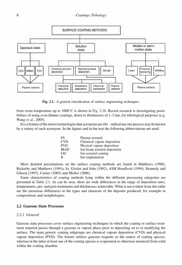
from room temperature up to 1000�C is shown in Fig. 2.2b. Recent research is investigating possi-bilities of using even thinner coatings, down to thicknesses of 1–3 nm, for tribological purposes (e.g.Wang et al., 2005).
It is a feature of the newer technologies that acronyms are rife – indeed any one process may be knownby a variety of such acronyms. In the figures and in the text the following abbreviations are used:
More detailed presentations on the surface coating methods are found in Matthews (1990),Rickerby and Matthews (1991a, b), Gissler and Jehn (1992), ASM Handbook (1994), Kennedy andGibson (1997), Cartier (2003) and Mellor (2006).
Some characteristics of coating methods lying within the different processing categories arepresented in Table 2.1. As can be seen, there are wide differences in the range of deposition rates,temperatures, pre- and post-treatments and thicknesses achievable. What is not evident from this tableare the enormous differences in the types and character of the deposits produced, for example incompositions and morphologies.
2.2 Gaseous State Processes
2.2.1 General
Gaseous state processes cover surface engineering techniques in which the coating or surface treat-ment material passes through a gaseous or vapour phase prior to depositing on to or modifying thesurface. The main generic coating subgroups are chemical vapour deposition (CVD) and physicalvapour deposition (PVD). The former utilizes gaseous reagents as the source of coating species,whereas in the latter at least one of the coating species is evaporated or otherwise atomized from solidwithin the coating chamber.
Fig. 2.1. A general classification of surface engineering techniques.
PA Plasma assistedCVD Chemical vapour depositionPVD Physical vapour depositionIBAD Ion beam assisted depositionIAC Ion assisted coatingII Ion implantation
8 Coatings Tribology

As shown in Table 2.1, these methods are of considerable interest for a number of reasons, not leastbecause they permit the deposition of pure ceramic films. In the case of PVD this requires a means ofincreasing the energy of the coating species, most typically by ionizing them and accelerating the ionstowards the growing film. This can be achieved by utilizing an ion beam source, or by initiatingplasma around the substrate, from which ions can be accelerated. Below we overview the CVD andPVD process technologies.
2.2.2 Chemical vapour deposition
In the basic chemical vapour deposition (CVD) process, gases containing material to be deposited areintroduced into a reaction chamber, and condense on to the substrate to form a coating. The processnormally requires deposition temperatures in the range of 800–1200�C. Figure 2.3 shows a hot-wallCVD layout typically used for tool coating with titanium nitride and titanium carbide.
Figure 2.4 shows the many derivatives of the basic CVD process. These have arisen in response toa need to achieve specific coating characteristics, such as epitaxial growth, improved hole penetrationor lower deposition temperatures. Furthermore, certain coating types (e.g. diamond) are onlyachievable using particular process technologies and parameters. In this sense CVD is now almost asdiverse in the variants available as PVD.
The deposition pressure in CVD can range from atmospheric down to 1 Pa or less. There are variousmeans of assisting the process, such as through the use of laser or electron beams, or by ion bom-bardment of the growing films. These methods promise the benefit of a reduction in coatingtemperatures necessary to obtain dense and well-adhered films.
Notwithstanding these developments, there is still considerable scope for the wider use of con-ventional non-enhanced thermally activated CVD coating methods for tribological applications. Thestrength of the technique lies in its ability to produce well-adhered, uniform and dense surface layers.The grain orientation and size, coating composition and its properties can be varied by the selection ofappropriate process parameters. The technique can be used to deposit a large number of wear-resistantcoatings such as borides, carbides, nitrides, oxides, carbo-nitrides and oxy-nitrides of almost all thetransition metals (Sudarshan, 1992). In particular the use of such coatings on substrates which are not
Fig. 2.2. Typical ranges for (a) depths of surface modifications and thicknesses of coatings, and(b) processing temperatures for coating technologies.
9Deposition Processes and Coating Structures

Table 2.1. Comparative typical characteristics of some of the main coating methods.
Gaseous State Processes Solution Processes Molten or Semi-MoltenState Processes
PVD PAPVD CVD PACVD IonImplantation
Sol-Gel Electro-Plating Laser ThermalSpraying
Welding
Depositionrate (kg/h)
Up to 0.5per source
Up to 0.2 Up to 1 Up to 0.5 0.1–0.5 0.1–0.5 0.1–1 0.1–10 3.0–50
Coatingthickness ortreatmentdepth (mm)
0.1–1000 0.1–100 0.5–2000 1–20 0.01–0.5 1–10 10–500 50–2000 50–1000 1000–10,000
Componentsize
Limited by chamber size Limited bysolution bath
May be limited by chambersize
Substratedepositionor treatmenttemperature(�C)
50–500 25–500 150–12,000 150–700 50–200 25–1000 25–100 200–2000 100–800 500–1200
Substratematerial
Metals,ceramics,polymers
Metals,ceramics
Metals,ceramics
Metals,ceramics
Metals,ceramics,polymers
Metals,ceramics,polymers
Metals,ceramics,polymers
Metals
Pretreatment Mechanical/chemical
Mechanical/chemical plus ionbombardment
Mechanical/chemical
Mechanical/chemicalplus ionbombardment
Chemicalplus ionbombardment
Grit blastand/orchemicalclean
Chemicalcleaning andetching
Mechanical andchemical cleaning
Post-treatment
None None Substratestress relief
None None Hightemperature
None/thermaltreatment
None/substratestress relief
None
Uniformityof coating
Good Good Very good Good Line ofsight
Fair/good Fair/good Fair Variable Variable
Bondingmechanism
Atomic Atomic plusdiffusion
Atomic Atomic plusdiffusion
Integral Surface forces Mechanical/chemical/ metallurgical
10
Co
atin
gs
Trib
olo
gy

temperature sensitive, such as cemented carbides, will continue, especially when the excellent coatinguniformity and recess penetration capabilities of this technique are required.
Carlsson (1991) has described schematically the reaction zones present in thermally activatedCVD, as shown in Fig. 2.5. A feature of this model is that a boundary layer is identified across whichthe reactants and reaction products are transported. This controls the deposition rate, while the het-erogeneous reactions in zone 2 usually define the microstructure of the coating. Typical CVD-deposited films for tribological applications, such as titanium nitride, have large-angle grainboundaries and grain sizes in the range 0.5–5 mm.
The microstructure depends critically on the deposition temperature, which for TiN is typically950�C, but for CVD in general can vary from room temperature up to over 1200�C. At higher tem-peratures various solid-state reactions, such as phase transformations, precipitation, recrystallization
Fig. 2.3. A typical CVD process layout.
Fig. 2.4. Some chemical vapour deposition-based coating processes and ion-based derivatives.
11Deposition Processes and Coating Structures
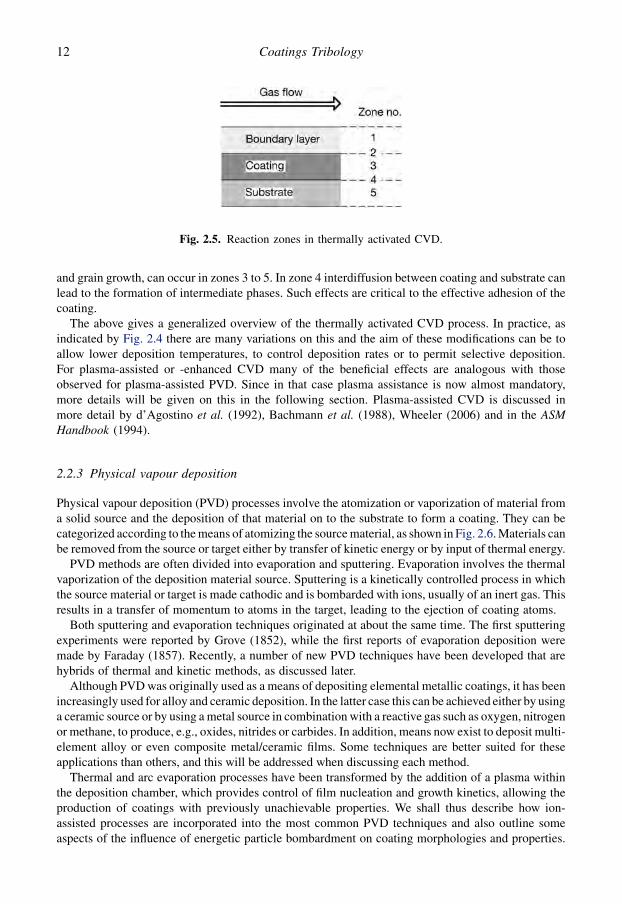
and grain growth, can occur in zones 3 to 5. In zone 4 interdiffusion between coating and substrate canlead to the formation of intermediate phases. Such effects are critical to the effective adhesion of thecoating.
The above gives a generalized overview of the thermally activated CVD process. In practice, asindicated by Fig. 2.4 there are many variations on this and the aim of these modifications can be toallow lower deposition temperatures, to control deposition rates or to permit selective deposition.For plasma-assisted or -enhanced CVD many of the beneficial effects are analogous with thoseobserved for plasma-assisted PVD. Since in that case plasma assistance is now almost mandatory,more details will be given on this in the following section. Plasma-assisted CVD is discussed inmore detail by d’Agostino et al. (1992), Bachmann et al. (1988), Wheeler (2006) and in the ASMHandbook (1994).
2.2.3 Physical vapour deposition
Physical vapour deposition (PVD) processes involve the atomization or vaporization of material froma solid source and the deposition of that material on to the substrate to form a coating. They can becategorized according to the means of atomizing the source material, as shown in Fig. 2.6. Materials canbe removed from the source or target either by transfer of kinetic energy or by input of thermal energy.
PVD methods are often divided into evaporation and sputtering. Evaporation involves the thermalvaporization of the deposition material source. Sputtering is a kinetically controlled process in whichthe source material or target is made cathodic and is bombarded with ions, usually of an inert gas. Thisresults in a transfer of momentum to atoms in the target, leading to the ejection of coating atoms.
Both sputtering and evaporation techniques originated at about the same time. The first sputteringexperiments were reported by Grove (1852), while the first reports of evaporation deposition weremade by Faraday (1857). Recently, a number of new PVD techniques have been developed that arehybrids of thermal and kinetic methods, as discussed later.
Although PVD was originally used as a means of depositing elemental metallic coatings, it has beenincreasingly used for alloy and ceramic deposition. In the latter case this can be achieved either by usinga ceramic source or by using a metal source in combination with a reactive gas such as oxygen, nitrogenor methane, to produce, e.g., oxides, nitrides or carbides. In addition, means now exist to deposit multi-element alloy or even composite metal/ceramic films. Some techniques are better suited for theseapplications than others, and this will be addressed when discussing each method.
Thermal and arc evaporation processes have been transformed by the addition of a plasma withinthe deposition chamber, which provides control of film nucleation and growth kinetics, allowing theproduction of coatings with previously unachievable properties. We shall thus describe how ion-assisted processes are incorporated into the most common PVD techniques and also outline someaspects of the influence of energetic particle bombardment on coating morphologies and properties.
Fig. 2.5. Reaction zones in thermally activated CVD.
12 Coatings Tribology

2.2.3.1 Plasma-assisted PVD
Although the basic PVD process has been known for over 150 years and the process which we nowcall plasma-assisted physical vapour deposition (PAPVD) was patented more than 70 years ago(Berghaus, 1938), it is only in the last few decades that PAPVD has begun to make a major mark asa tribological coating method. This is because the process has only recently been more fullyunderstood at a fundamental level and the necessary modifications introduced to provide benefits suchas those in the list below. These are the main advantages for such plasma-assisted processes, whichprincipally relate to PVD but in several cases are also pertinent to plasma-assisted CVD:
1. Improved coating adhesion, due to the ability to clean and pre-heat substrates by energetic ion andneutral bombardment of the substrate surface. This mechanism is sometimes called sputtercleaning.
2. Uniform coating thicknesses, through gas-scattering effects and the ability to rotate or displacesamples relative to the vapour source during deposition.
Fig. 2.6. Techniques used to atomize the source materials in PVD.
13Deposition Processes and Coating Structures

3. Avoidance of a final machining or polishing stage after coating, as in most cases the coatingreplicates the original surface finish.
4. Controlled coating structures, due to the effect of bombardment in encouraging adatom mobilityand obviating columnar growth.
5. Deposition of a wide range of coating and substrate materials, including dielectrics, usually by theuse of radio frequency or pulsed substrate biasing.
6. Controllable deposition rates, using a wide variety of vapour sources including resistance heated,electron beam, arc, induction and sputter magnetron.
7. Usually no effluents or pollutants are produced, as in most cases there are no harmful by-productsor toxic chemical solutions used.
8. High purity deposits through the use of a controlled vacuum environment and pure sourcematerials.
9. Lower deposition temperatures, as direct energization of the coating species provides many of thebenefits previously only achievable on hot substrates. Thus lower bulk substrate temperatures canbe used for ceramic deposition compared to non-plasma-assisted vapour deposition.
10. Avoidance of the hydrogen embrittlement problems sometimes experienced in electroplating.
The flexibility of the PVD coating process can be seen from Fig. 2.7, which shows how the coatingstructure can be varied as a function of deposition pressure and temperature according to Thornton(1974). Morphology is discussed in detail later in this chapter and in Chapter 5.
The advantages of the PAPVD processes extend beyond those listed. They include the possibility todeposit alloy compounds, multilayer compositions and structures, and the ability to vary coatingcharacteristics continuously throughout the film, giving the concept of a functionally graded coating.The developments leading to these improvements have been many and varied and this has produceda proliferation of techniques and acronyms for various processes, as illustrated in Fig. 2.8.
This figure gives only a few of the many variations. In the field of diamond deposition, for example,there are probably almost as many processes or process variants being investigated as laboratories inthe field.
Consider first the basic PAPVD process, which is also called ion plating. This was originallyenvisaged as being carried out at a reduced pressure, with the sample to be coated as the negativeelectrode in a glow discharge of argon. This led to the sputter-cleaning of the surface with argon ions
Fig. 2.7. Schematic representation of the influence of substrate temperature and argon pressure on themicrostructure of metal coatings deposited using cylindrical magnetron sputtering sources. T (K) is thesubstrate temperature and Tm (K) is the melting point of the coating material (Thornton, 1974).
14 Coatings Tribology

and accelerated neutrals. Subsequently, the metal to be deposited was evaporated into the glow dis-charge or plasma, itself being ionized to an extent and arriving at the substrate surface with increasedenergy. This simple concept still lies at the heart of all PAPVD methods, though increasingly the levelof ionization achieved is enhanced by some means in order to maximize or control the effectsoccurring.
The main mechanisms arising due to accelerated ion or neutral bombardment of a surface areillustrated by Fig. 2.9. One of the most important is the sputtering mechanism. This is generallyconsidered to involve a momentum transfer process, in which the arriving atoms cause other atoms orclusters of atoms to be knocked free from the surface. This is important for three main reasons. First, itallows the surface to be cleaned of unwanted species prior to coating. Second, it allows the formationof a pseudo-diffusion layer between the substrate and coating, due to the forced intermixing ofsubstrate and coating atoms during interface formation. Third, the sputtering mechanism isresponsible for the continuous redistribution of surface coating atoms during film growth – which canlead to effects such as film densification.
Many of the effects created by accelerated ion or neutral bombardment can be enhanced byincreasing the amount of ionization occurring, i.e. by ensuring that a larger proportion of the speciesarriving at the surface are in fact ionized. It has been shown that, provided some critical minimumenergy is exceeded, it is more advantageous to increase the amount of ionization, i.e. the ionizationefficiency, than to increase the energy, i.e. the acceleration voltage of the individual ions (Matthews,1980).
One of the first systems to achieve ionization enhancement was the activated reactive evaporation(ARE) system (Bunshah and Raghuram, 1972), which was then modified to the biased ARE (BARE)system (Koboyashi and Doi, 1978) shown in Fig. 2.10a. These systems utilized an additional electrodein the deposition chamber, to increase the potential of the plasma, and ensure more effective ioni-zation, essentially by making use of electrons emitted from the vapour source or cathodic surfaces
Fig. 2.8. (a) Some physical vapour deposition-based coating processes and (b) plasma derivatives.
15Deposition Processes and Coating Structures

within the chamber or both. An alternative is to insert an electron emitter into the system, in the formof a heated filament. This is used in the thermionically enhanced triode system (Matthews, 1980)shown in Fig. 2.10b.
As originally conceived the above systems utilized an electron beam gun to evaporate the sourcematerial. However, a variety of other methods can be used to achieve this. Some of the vapour sourcesthemselves increase ionization.
Fig. 2.9. Surface effects occurring during ion bombardment (after Weissmantel, 1983).
Fig. 2.10. (a) Layout of the biased activated reactive evaporation system and (b) the thermionicallyenhanced triode system.
16 Coatings Tribology

As described in Fig. 2.6, the main techniques available to vaporize the coating material are: re-sistance-heated sources, electron beam guns, induction-heated sources, arc sources and sputtersources.
1. Resistance heating involves holding the evaporant in a holder, sometimes a filament or a so-called‘boat’, made from a refractory material such as tungsten or molybdenum, or an intermetalliccompound such as titanium diboride/boron nitride. The container is heated by passing a currentthrough it. This method has been used for evaporating low-melting point materials such asaluminium, copper, silver and lead.
2. Electron beam guns have become popular for depositing thin ceramic coatings such as TiN and alsofor thicker bond coats and thermal barriers for gas turbine components. There is effectively no limiton the melting point of materials that can be evaporated, and the deposition rates achievable tend tobe higher than other PVD methods. The most popular types of gun used are the bent beam self-accelerated gun (Schiller et al., 1986; Pulker, 1984), the work accelerated gun (Moll and Daxinger,1980; Hill, 1986), and a variant of the latter, known as the hollow cathode discharge (HCD)electron beam gun (Morley and Smith, 1972).
The last two systems, shown in Fig. 2.11, are very effective in increasing the ionization whenused in ion plating systems. In the work accelerated electron beam gun system the electron beam(shown dotted) passes through the deposition chamber, thereby enhancing ionization of the coatingspecies, which deposit on the sample. In the hollow cathode discharge gun system the electronbeam is generated by confining plasma inside the tube. This leads to the emission of the beam.
3. Like electron beam heating, induction heating has the advantage that the heat can be directed to themelt material, rather than to the boat or crucible. This can reduce evaporant crucible reactions andis particularly attractive for materials such as titanium and aluminium.
4. Arc evaporation was used for many years as a means of vaporizing carbon – simply by striking anarc between two carbon electrodes. Considerable interest has surrounded the use of the arc tech-nique to evaporate various metals (Sanders et al., 1990; Boxman et al., 1996; Sanders and Anders,2000). A typical layout is shown in Fig. 2.12. This method also enhances the ionization of thedepositing species. A further benefit is that, because no molten pool is formed, evaporators can befitted in any orientation. However, a reported disadvantage for this technique is that droplets areejected from the source producing macroparticles in the coatings.
Fig. 2.11. (a) Layout of the work accelerated electron beam gun system and (b) the hollow cathodedischarge gun system.
17Deposition Processes and Coating Structures

5. Sputtering sources utilize the sputter mechanism described earlier, to produce the atomistic coatingspecies through the bombardment of a source or target by ions and accelerated neutrals, usually ofargon. A major advantage of this approach is that alloys can be sputter deposited to retain theircomposition. New magnetrons have been developed which unbalance the magnetic field, such thatthe plasma associated with the target is released into the deposition volume, to provide a higherlevel of ionization of the depositing species (Sproul et al., 1990; Rohde et al., 1990; Rohde andMunz, 1991; Matthews et al., 1993; Matthews, 2003).
Since it is probably true to say that the majority of new coatings reported in this book are producedusing sputter deposition technologies, we shall outline below some of the key technologicaldevelopments pertinent to sputter deposition.
2.2.3.2 Sputter deposition
The simplest sputtering plasma deposition layout is that of direct current diode glow discharge, sincethere are only two electrodes, a positive anode and a negatively biased cathode. Very simply, sputterdeposition can then be carried out with the substrate earthed. If the potential applied between thesetwo electrodes is constant over time it is termed a direct current (DC or dc) diode discharge. However,if this potential changes with time it may be either a pulsed-diode discharge (unipolar or bipolar), or ifthe frequency is sufficiently high and reverses in polarity, it becomes a radio frequency (RF or rf)diode discharge. Each of these has relative advantages and disadvantages, particularly in terms ofceramic deposition.
Although DC-diode sputtering was used in the 19th century to deposit thin metallic films onmirrors, it was not until reliable radio frequency sputtering was developed in the 1970s that it waspossible to sputter dielectric materials. Since many ceramic thin film materials are good insulators,most early applications of sputtering were limited to the deposition of metallic coatings. Directcurrent diode sputtering would probably not have been widely used in the deposition of ceramic thinfilms if the technology necessary for high-rate reactive sputtering from a metallic target had not beendeveloped in the early 1980s (Sproul, 1983; Sproul and Tomashek, 1984).
Fig. 2.12. Layout of an arc source system.
18 Coatings Tribology
Provided that the target material is sufficiently conductive, the target can be effectively sputteredusing simple DC-diode geometry. Typically in DC-diode sputtering a potential of several hundredvolts is applied between the cathode and anode, and gas pressures in the range from about 0.5 Pa up totens of Pa are used to generate the plasma. The substrates can be heated or cooled, and held at groundpotential, electrically isolated (i.e. floated), or biased relative to the plasma.
The use of an oscillating power source to generate the sputtering plasma offers several advantagesover direct current methods. The main one is that when the frequency of oscillation is greater thanabout 50 kHz, it is no longer necessary for both electrodes to be conductive because the electrode canbe coupled through an impedance (Hill, 1986) and will take up a negative DC offset voltage due to thegreater mobility of electrons compared to ions in the reversing field. The coupled electrode must bemuch smaller than the direct electrode in order to effectively sputter only the insulating (coupled)electrode. This is usually accomplished by utilizing the grounded chamber walls as the other elec-trode. An impedance matching network is integrated into the circuit between the RF generator and theload to introduce the inductance necessary to form a resonant circuit.
An additional benefit of using frequencies above 50 kHz is that the electrons have a longer resi-dence in the negative glow region and also have sufficient energy to directly ionize the gas atoms;hence, the number of electrons required to sustain the discharge is substantially reduced (Vossen andCuomo, 1978; Chapman, 1980; Thorton, 1982). This, in turn, means that lower sputtering pressurescan be used, reducing the risk of film contamination. The most commonly used frequency for rfsputtering is 13.56 MHz.
Unfortunately, the deposition rates in RF sputtering of ceramic target are often limited by the lowsputter yield and thermal conductivity of the insulating target materials. This low thermal conductivityof the materials can lead to the formation of ‘hot spots’ on the target. The hot spots generate stressesthat may cause fracture of the brittle target materials. Thus, it may be preferable to deposit insulatingfilms reactively from a metal source.
The availability of sophisticated electrical supplies, capable of providing controlled pulsed powerwaveforms in tandem with excellent arc suppression, has opened up new opportunities in sputterdeposition (e.g. Schiller et al., 1993, 1995). In particular, pulse power has proved to be highly effectivein the reactive sputtering of oxide coatings. Sproul (1996) has described the use of bipolar pulse powerfor sputtering of metal targets in oxygen as follows. The polarity of the target power is switched fromnegative to positive, and during the positive pulse any charging of oxide layers formed on the targetsurface is discharged when electrons are attracted to the positive surface. During the negative pulse,ions are attracted to the target surface and sputtering takes place initially from all surfaces on thetarget, even those that have formed a compound, since the charge on that surface has been neutralizedduring the positive pulse.
Bipolar pulse power can be either symmetric or asymmetric, depending on the relative positive andnegative maximum voltages (Scholl, 1996). Pulsed DC power is said to be symmetric if these voltagesare equal. With modern power supplies it is possible to control the on and off time for the pulses.
The successful use of symmetric bipolar pulsed DC power has been reported for the deposition ofoxide coatings from two magnetron targets. These targets, mounted side by side, are both connected tothe same bipolar pulsed DC power supply. One DC power lead is connected to one target, and theother to the second target. With this system, one of the sputter targets is briefly the anode, whilethe other is the cathode, and this continuously swaps, with reversals in polarity. Sputtering from thecathode surface during the negative pulse keeps the target surface clean, and when it switches to act asan anode it is not covered by an oxide. As pointed out by Sproul, this procedure avoids the ‘disap-pearing anode’ problem, which can occur in pulsed DC sputtering of oxides when all surfaces in thechamber become covered with an insulating oxide.
Asymmetric bipolar pulsed DC has unequal pulse heights and will be applied to one target. Usually,the negative pulse voltage is greater than the positive one and in this case there is usually no off timebetween pulses. The width of the positive pulse is typically 10–20% of the negative one, thus a high
19Deposition Processes and Coating Structures

proportion of the cycle is spent in sputtering mode, providing deposition rates which are near to thosefor non-reactive DC sputtering of metals provided that pulsed DC power is combined with effectivepartial pressure control.
2.2.3.3 Magnetron sputter deposition
Usually, the beneficial biasing arrangements described above are applied to magnetron sputteringtargets, in which a magnetic field is used to trap electrons in the vicinity of the target and to spiral themround a ‘racetrack’, thereby increasing the degree of ionization occurring and therefore the sputteringrate. Probably the greatest research advances in PVD tribological coatings have occurred around themagnetron sputtering process.
The benefits of magnetrons in sputtering have been known for several decades, i.e. in terms ofreducing the required pressure and increasing the deposition rate. However, until recently magnetronsputtering was found to be less effective as a means of producing hard ceramic coatings on tools andcomponents than electron beam and arc evaporation. This was because the levels of ionizationachieved were considerably less than those possible with the enhanced plasmas which are charac-teristic of these other methods.
The most important step in improving the competitiveness of magnetron sputtering was reported byWindow and Savvides (1986) and Savvides and Window (1986), when they described their studies onthe unbalanced magnetron (UBM) effect. They found that the ion flux to the substrate could beconsiderably increased by running magnetron cathodes in unbalanced mode (UM). They identifiedthree main magnetic arrangements shown in Fig. 2.13. In the Type I configuration all the field linesoriginate from the central magnet, with some not passing into the outer magnet. In the intermediatecase all of the field lines starting on the central pole go to the outer pole. In the Type II configuration,all of the field lines originate in the outer magnet, with some not passing to the central pole. Followingthe work of Window and Savvides, a number of researchers began building upon these concepts.
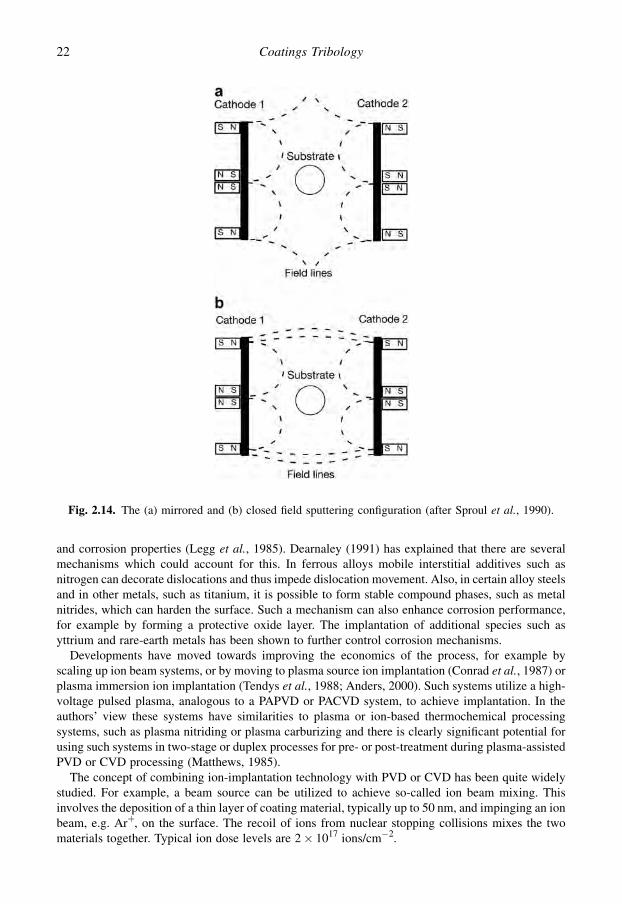
In the late 1980s Sproul and his co-workers researched multi-cathode high-rate reactive sputteringsystems (Sproul et al., 1990; Rohde et al., 1990). They studied different magnetic configurations,principally in the dual-cathode arrangement shown schematically in Fig. 2.14. They found that bystrengthening the outer magnets of a magnetron cathode with NdFeB and arranging two of thesemagnetrons in an opposed closed field configuration, i.e. with opposite poles facing each other, thesubstrate bias current could be increased to well over 5 mA/cm2 at a pressure of 0.7 Pa. Under theseconditions they were able to deposit hard well-adhered titanium nitride coatings.
Another person utilizing the opposed magnetron configuration at that time was Tominaga (1990).He presented an arrangement whereby the permanent magnetic field could be increased by externalelectromagnetic coils. He stated that this allowed the trapping of electrons by the closed field ar-rangement to increase ionization or to allow lower working gas pressure with the same level ofionization as achievable with conventional magnetron sputtering.
Another group which has researched confined and unbalanced magnetron sputtering is that led byKadlec (Kadlec et al., 1990a, b), who in early collaboration with Munz investigated a circular planerunbalanced magnetron arrangement surrounded by two magnetic coils and a set of permanentmagnets. They described this as a multipolar magnetic plasma confinement (MMPC), and cite highion currents at substrates, even when located at large distances from the magnetron.
Howson and co-workers have also studied unbalanced magnetrons, especially for high-power largearea applications (Howson et al., 1990, 1992) and demonstrated how additional anodes or electro-magnets can be used to control the ion current to the substrate. This may be seen as an extension ofearly work by Morrison (1982) and Morrison and Welty (1982) who demonstrated that a ‘magneti-cally hidden’ anode placed in a magnetron sputtering system could double the plasma density andprovide a more uniform plasma throughout the chamber. Several commercial companies have nowadopted variations on closed field and anodically enhanced systems, as discussed by Matthews (2003).
20 Coatings Tribology

For further details on the plasma-assisted vapour deposition processes see Matthews (1985, 2003),Rickerby and Matthews (1991a, b), Moll (1992), Pauleau (1992), ASM Handbook (1994), Bunshah(1994) and Ohring (2002).
2.2.4 Ion and laser beam-assisted deposition and surface treatment
The ion–surface interaction effects illustrated in Fig. 2.9 include the possibility that the ions will havesufficient energy to become embedded within the surface. This can provide a means of enhancing thetribological properties, although not producing a coating. Typically, this is achieved by generatinga high-energy ion beam in a separate source as shown in Fig. 2.15.
The introduction of elemental species such as nitrogen, titanium, carbon or yttrium into the surfaceof many metals, ceramics, cermets or even polymers has been shown to improve wear, friction, fatigue
Fig. 2.13. Three types of magnetron configurations: Type I, Intermediate and Type II (after Window andSavvides, 1986).
21Deposition Processes and Coating Structures
and corrosion properties (Legg et al., 1985). Dearnaley (1991) has explained that there are severalmechanisms which could account for this. In ferrous alloys mobile interstitial additives such asnitrogen can decorate dislocations and thus impede dislocation movement. Also, in certain alloy steelsand in other metals, such as titanium, it is possible to form stable compound phases, such as metalnitrides, which can harden the surface. Such a mechanism can also enhance corrosion performance,for example by forming a protective oxide layer. The implantation of additional species such asyttrium and rare-earth metals has been shown to further control corrosion mechanisms.
Developments have moved towards improving the economics of the process, for example byscaling up ion beam systems, or by moving to plasma source ion implantation (Conrad et al., 1987) orplasma immersion ion implantation (Tendys et al., 1988; Anders, 2000). Such systems utilize a high-voltage pulsed plasma, analogous to a PAPVD or PACVD system, to achieve implantation. In theauthors’ view these systems have similarities to plasma or ion-based thermochemical processingsystems, such as plasma nitriding or plasma carburizing and there is clearly significant potential forusing such systems in two-stage or duplex processes for pre- or post-treatment during plasma-assistedPVD or CVD processing (Matthews, 1985).
The concept of combining ion-implantation technology with PVD or CVD has been quite widelystudied. For example, a beam source can be utilized to achieve so-called ion beam mixing. Thisinvolves the deposition of a thin layer of coating material, typically up to 50 nm, and impinging an ionbeam, e.g. Arþ, on the surface. The recoil of ions from nuclear stopping collisions mixes the twomaterials together. Typical ion dose levels are 2� 1017 ions/cm�2.
Fig. 2.14. The (a) mirrored and (b) closed field sputtering configuration (after Sproul et al., 1990).
22 Coatings Tribology

It is not always necessary to physically ion beam mix the interface atoms to improve the film-to-substrate bond, especially on ceramic and polymer surfaces (Parker, 1974). The bond of a thin coating toa substrate can often be improved by lightly implanting through the interface. This process is sometimescalled ion beam stitching. Low doses can be used for this technique such as 1015 to 1016 ions/cm2.
Ion beam-assisted deposition (IBAD) in which deposition and ion irradiation are simultaneouslycombined is useful in forming compound films. Both structural and chemical properties can be mod-ified. Sometimes the technique goes under the name ion-assisted coating (IAC). If the bombarding ionsare reactive species then the process is known as reactive ion beam-assisted deposition (RIBAD).Sometimes a combination of techniques is used. For example, a very thin layer may first be deposited,e.g. by sputtering or electron beam evaporation, and then intermixed with the substrate using an ionbeam. Further depositions are then combined with ion implantations to produce a final coating overa highly intermixed interface. This type of ion-assisted coating, usually carried out with reactive ionbeams such as nitrogen, carbon or oxygen, has been termed reactive ion-assisted coating (RIAC).
The four main ion beam techniques for surface modification or treatment are shown in Fig. 2.16(Legg et al., 1985) and an ion-assisted coating layout is schematically shown in Fig. 2.17.
Over many years there have been many publications dealing with ion beam and related plasma-based techniques to deposit diamond and diamond-like carbon (DLC) (Aisenberg and Chabot, 1971;Angus et al., 1986; Dehbi-Alaoui et al., 1991; Voevodin et al., 1995). A further variation on this themeis the filtered-arc source (McKenzie et al., 1991; Martin et al., 1992; Zhitomirsky et al., 1994) whichutilizes a deflection coil to eliminate macrodroplets and produce a beam of ionized atoms, which canbe carbon, for DLC films, or a metal such as titanium, for reactive deposition of a ceramic.
Another important beam technique in PVD is pulsed laser deposition. According to Voevodin andDonley (1996) this is especially appropriate for DLC coatings, as the controlled energy rangeachievable for the arriving species is wider than other techniques. Also flux control and speciescontrol are said to be excellent, for example non-hydrogenated DLC can readily be produced. Severalceramics have also been deposited by this method (Prasad et al., 1995; Voevodin et al., 1996). Lasersurface treatments are further discussed in section 2.4.1.
2.3 Solution State Processes
The main coating techniques in this category are electroplating and electroless plating. The solutionsused are usually aqueous, and deposits can be produced on metallic or non-metallic substrates.Methods may be divided into the categories of chemical and electrochemical, but this division maynot be straightforward since some reactions which appear to be purely chemical may in fact beelectrochemical (Lowenheim, 1978; Cartier, 2003).
Fig. 2.15. Schematic of a typical ion source.
23Deposition Processes and Coating Structures

One of the benefits of the solution processes is that they have no upper limit on thickness. In thissense they differ from vapour deposition methods, which, because of stress build-up leading todebonding, are typically used for films less than 10 mm thick, when hard ceramics are deposited.
2.3.1 Chemical solution deposition
Within chemical solution deposition methods we find:
� homogeneous chemical reactions, e.g. reduction of a metal ion in solution by a reducing agent,� electroless or autocatalytic deposition, which is similar to the previous, except that the reaction
takes place on surfaces which are catalytic, rather than throughout the solution, and� conversion coatings, where a reagent in solution reacts with the substrate, to form a compound.
Fig. 2.16. The four main ion beam-based coating techniques (after Legg et al., 1985).
24 Coatings Tribology

The chemical reduction process is used, for example, by spraying a solution of metal ions and re-ducing agents on to a surface, such that the metal coating builds up. The technique can work on metalsand plastics, but the adhesion levels can be poor. Examples of coating materials which can be de-posited in this way are silver, gold and copper.
Electroless deposition of nickel, normally with phosphorus or boron additions, is an increasinglyimportant coating technology. The additions derive from the reducing agents used, e.g. sodiumhypophosphite or aminoboranes, typically with nickel sulphate. A significant advantage of theelectroless nickel process is that it can be used in conjunction with finely divided particles, in the Ni–Pbath for example, to produce composite coatings. Examples of materials used to reinforce the coatingsin this way are SiC, WC, CrC, Al2O3, or diamond (Parker, 1974; Celis et al., 1988). Alternatively,solid lubricant particles, such as graphite, PTFE or calcium fluoride, may be added (Ebdon, 1987).Electroless plating has been reviewed by Ponce de Leon et al. (2006).
Chemical conversion coating methods include phosphating and chromating. The main use of theformer is to enhance the corrosion barrier properties of steels or aluminium prior to painting. Thelayer, produced by reaction with phosphoric acid, can be either an amorphous or a crystallinephosphate. Sometimes this layer is applied as an aid to the lubrication of moving parts by providinga degree of protection against scuffing and to facilitate running-in. Chromate conversion coatings areapplied by immersing or spraying a surface with an aqueous solution of chromic acid, chromic salts,phosphoric acid or other mineral acids. The surfaces develop an oxide film which is sealed bya metallic chromate. The process is typically applied to steel, aluminium, magnesium, cadmium andzinc (Celis et al., 1988). It improves the corrosion properties and can enhance paint adhesion.
2.3.2 Electrochemical deposition
Electrochemical deposition, also commonly termed electroplating, involves the deposition of ametallic coating on an electrode by a process of electrolysis, whereby chemical changes are producedby the passage of a current. Michael Faraday first put forward the laws of electrolysis in 1833, and
Fig. 2.17. An ion-assisted coating arrangement (original copyright AEA Technology, Rickerby andMatthews, 1991a).
25Deposition Processes and Coating Structures

they still form the basis of the technology, such as (1) the amount of chemical change produced isproportional to the quantity of electricity which passes, and (2) the amounts of substances liberated bya given quantity of electricity are proportional to their equivalent weights. A schematic electroplatinglayout is shown in Fig. 2.18. The electrochemical deposition techniques are described, e.g., by Willsand Walsh (2006).
Without going into detail about the chemical aspects of the process, we can state that the metalsdepositable from aqueous solutions generally occupy a region in the middle of the periodic table asshown in Fig. 2.19.
Among the metals listed, many are deposited as alloys, e.g. brass (Cu–Zn), bronze (Cu–Sn), Co–Ni,Fe–Ni, Sn–Ni, Sn–Zn and Sn–Pb (Lowenheim, 1978). The most electronegative metal commonlyplated is Zn, which when deposited on steel provides galvanic protection, as does cadmium.
One of the most common electroplated tribological coatings is chromium plate, which is oftenCu/Ni/Cr or Ni/Cr, the Cr being only a very thin overlayer to prevent tarnishing of the Ni (Lowenheim,1978). Hard chrome is a term often used for thicker chromium deposits which have good abrasion andlubricant-retention properties.
A few electroplating processes use non-aqueous solutions, and some metals have been depositedfrom solvents such as liquid ammonia. The two main alternatives to aqueous baths are organic sol-vents and fused salts, though both present problems, e.g. in terms of toxicity hazards, disposal andcost. However, there are certain metals, such as aluminium, whose deposition by these routes isactively carried out (Ross, 1988).
2.3.3 Sol-gel processing
A sol is a colloidal dispersion of particles in a liquid, usually aqueous but sometimes an organosol.Sol-gel processing may be carried out by dipping, spinning, spraying or roller bar draw coating. Itinvolves applying the sol to a substrate, whereupon it undergoes hydrolysis and condensationreactions to form an aggregate gel. Final drying leads to further condensation and the formation ofa dense surface film.
Fig. 2.18. Typical electroplating layout.
26 Coatings Tribology

Typically, the technique is used for the production of oxide ceramic films, in which case the gel isfired at above 150�C to leave the ceramic, but also much higher temperatures of up to 900�C can beused (Bhushan and Gupta, 1991; Schmidt, 1994). There is less knowledge about the tribologicalproperties of sol-gel films than those produced by other techniques (Zhang et al., 2002). The mainpublished use of sol-gel-derived coatings in tribology seems to be for friction or corrosion control(Wang and Akid, 2007), and then, typically, a hybrid polymer/metal oxide film is applied (Lai et al.,2007; Voevodin et al., 2003). There are various reports of such films being used to improve theabrasion and scratch resistance of polymers (Li et al., 2000).
Where sol-gel-derived coatings have been used to enhance the abrasion resistance of metallicsubstrates, a high-temperature post-treatment is almost always used and variously described asannealing (Zhang et al., 2006a) or sintering (Liu et al., 2003). It should be noted though that where thepolymeric constituent in the hybrid composites are beneficial, as in erosive impact conditions, sucha very high-temperature treatment is avoided (Grundwurmer et al., 2007).
Thus one can summarize sol-gel methods as being useful for producing composite coatings, oftenwith controlled structural characteristics such as porosity, but they should be used as part of anextended processing route, usually requiring additional heat treatment in order to obtain the desiredstructure and adhesion. The technique also has potential as a means of producing spherical particles ofcontrolled size, which can then be used in plasma spraying processes (Bhushan and Gupta, 1991;Schmidt, 1994; Liu et al., 2003).
2.3.4 Plasma electrolysis
This is an electrolytic plasma-based process, which is carried out in a liquid electrolyte. It is especiallysuitable for producing hard ceramic surface layers on lightweight metals such as aluminium, mag-nesium and titanium (Yerokhin et al., 1999). It is probably best known as a means of forming a hardoxide surface on aluminium and magnesium, although variants of this technique can be used toproduce carbonitrides, and also to create surfaces which incorporate other metals, ceramics and evenorganic compounds. The plasma electrolytic processes are therefore gaining increasing importance intribological applications, especially for lightweight components, and as a supporting layer for sub-sequent deposits or impregnation treatments (Nie et al., 2000).
2.4 Molten and Semi-Molten State Processes
Within this category may be included laser surface treatments, and the hard-facing techniques ofthermal spraying and welding. Each of these subjects covers a very wide field, but since this book isintended primarily to emphasize thin tribological coatings, only a brief mention will be made of each.
Fig. 2.19. The long-form periodic table, showing the elements depositable from aqueous solution withinthe shaded area.
27Deposition Processes and Coating Structures

2.4.1 Laser surface treatments
A review of this subject has been compiled by Fellowes and Steen (1991), who list the followingtribological uses for lasers in surface treatment and coating:
� surface heating for transformation hardening or annealing,� surface melting for homogenization, microstructure refinement, generation of rapid solidification
structures and surface sealing,� surface alloying for improvement of corrosion, wear or aesthetic properties,� surface cladding for similar reasons as well as changing thermal properties such as melting point or
thermal conductivity, and� plating by laser chemical vapour deposition (LCVD) or laser physical vapour deposition (LPVD).
The latter can use laser heating of the evaporant in PVD, usually using a continuous wave laser, ora pulsed laser to ablate the source material in which case the term laser ablation deposition (LAD) issometimes used.
In the context of this book the coating techniques which lasers facilitate are of great interest. Onebenefit of lasers is that they can provide a directable deposition in defined areas (e.g. in LCVD). Whenused as a means of producing the vapour in PVD, where the laser ablates the source material, thetechnique is said to allow the composition of an alloy target to be retained in the coating. For furtherdetails of laser surface treatments, see Frenk and Kurz (1992) and Man (2006), and for a widerperspective on pulsed laser deposition, see Eason (2006).
2.4.2 Thermal spraying
Thermal spraying covers a wide range of techniques in which material is heated rapidly in a hotgaseous medium and simultaneously projected at high velocity onto a surface to produce a coating(Scott and Kingswell, 1991; Guilemany and Nin, 2006). According to Grainger (1989), processes forthermal spraying can be grouped into two categories. First, there are lower energy processes oftenreferred to as metallizing, which include arc and flame spraying. These are frequently used forspraying metals for corrosion resistance, such as zinc and aluminium. Second, there are the higherenergy processes such as plasma spraying, the detonation gun and high-velocity combustion spraying.A technique attracting considerable interest is the high-velocity oxy-fuel (HVOF) process, as shownin Fig. 2.20.
In all cases the types of structures differ considerably from those produced by either gaseous orsolution-state processes. Further details on plasma spraying are given by Brossa and Lang (1992),Cartier (2003) and Pawlowski (2008).
2.4.3 Welding
Various welding processes can be used to deposit a wide range of metals and metal/ceramic com-posites. The two most widely used methods are the oxyacetylene torch and arc welding. Thesetechniques can be applied to most metals, but they are not generally recommended for coating non-ferrous ones having melting points below 1100�C. The thickness range is generally 1.5 to 6.0 mm.Coating materials are usually applied to resist abrasive wear, and typically contain carbides ofchromium, tungsten or boron dispersed in a matrix of iron, cobalt or nickel. Those used to resistimpact generally have austenitic structures which work harden, e.g. austenitic manganese steel. This,as deposited, is relatively soft (approx. 170 Hv), but hardens to about 550 Hv when subjected toimpact conditions. This material gives an example of how the processing route can affect the coatingproperties. The austenitic structure of manganese steel is normally produced by a water quench from
28 Coatings Tribology

about 980�C. The alloys used for weld deposition are usually formulated to ensure that the austeniticstructure is obtained on air cooling from the welding temperature (HMSO, 1986; Mellor, 2006).
2.4.4 Other developments
Although molten and semi-molten state processes are regarded by many as mature technologies, thereare several developments being made of which two are described below.
2.4.4.1 Electro-spark deposition
This is a pulsed-arc micro-welding process using short-duration, high-current electrical pulses todeposit an electrode material on a metallic substrate. It is one of the few methods available by whicha fused, metallurgically bonded coating can be applied with such a low total heat input that the substratematerial remains at or near ambient temperature (Johnson, 1988). This is achieved by controlling thespark duration to a few microseconds and the spark frequency to around 1000 Hz. The substrate iscathodic and the source material is the anode. The sparking frequency can be controlled by vibratingone of these electrodes to vary the gap distance or, alternatively, triggering circuits can be used.
One of the earliest reported examples of electro-spark deposition (ESD) was the sparking of atitanium surface under oil, to produce a titanium carbide layer (Welsh, 1958). Nowadays, ESDcoatings are applied in air, argon, nitrogen, helium, CO2 and various mixtures of gases commonlyused in other arc welding processes. While gloveboxes may be required for control of environmentsfor highly reactive materials, an appropriately controlled flow of argon can usually effectively shieldthe surface.
The transfer of material from the anode has been described as globular or spray, depending on thevoltage and current conditions and the gas used. Anode materials can be virtually any electricallyconducting metal or cermet capable of being melted in an electric arc. The most commonly deposited
Fig. 2.20. Typical high-velocity oxy-fuel process layout.
29Deposition Processes and Coating Structures

ones are the refractory metal carbides and the cobalt- and nickel-based hard-facing alloys (Levashovet al., 2004, 2007). The next most important are materials to improve corrosion or oxidation resistanceof surfaces, such as chromium and aluminium alloys, and noble metals such as iridium, platinum andgold. Carbon, which does not have a molten phase at atmospheric pressure, does not appear to bea suitable material for ESD. Graphite electrodes have, however, been used to thinly carburize somestrong carbide formers such as titanium. An interesting innovation is the deposition of Fe-basedamorphous alloys with Vickers hardness levels over 1500 kgf/mm2 by ESD (Liu et al., 2007).
Rough surfaces are difficult to coat by ESD, as are holes or internal angles. Likewise, sharp knife-edges tend to blunt when subjected to ESD. Coating rates vary with the coating material and thethickness required. For example, to produce dense smooth coatings 25 mm thick, the rate of coveragemight be as low as 1 cm2/min. This low rate may be mitigated by the automation of the process and theuse of multiple applicator heads. Typical thicknesses from 3 mm to 250 mm have been quoted, al-though some deposits greater than 1 mm thick have been reported for nickel-based alloys. Furtherinformation on the process is given in Lesnjak and Tusek (2002).
2.4.4.2 Friction surfacing
This method achieves many of the benefits of welding but without the torch or flame. The coatingmaterial, usually in rod form, is rotated at high speed and forced against the substrate. Frictionalheating generates a hot plasticized zone at the interface. Movement of the substrate across the face ofthe rotating rod transfers a layer of coating material onto the substrate, giving a build-up of 0.2 to2.5 mm. The solid phase joining of the coating to the substrate avoids many of the problems associatedwith fusion welding or thermal spray processes. The result is a well-bonded dense coating with a finemicrostructure. The process is capable of depositing many of the hard wear-resistant alloys, from lowalloy steels through tool steels to the cobalt-based alloys. Likewise, many of the alloys traditionallyused for corrosion resistance such as stainless steels, nickel-based alloys and aluminium bronzes canalso be deposited (Doyle and Jewsbury, 1986; Bedford and Richards, 1986). Further details on theprocess are given in Mellor (2006).
2.5 Surface Hardening Treatments
Engineering surfaces are often hardened, usually by thermal or thermochemical means, to improvetheir tribological and corrosion properties. While not within the definition of tribological coatings wehave adopted within this book, these treatments are mentioned here, especially since they aresometimes used as precursors to provide a load supporting surface layer beneath the tribologicalcoating. This aspect is discussed further in sections 3.4.2 and 4.6.4.
Thermal treatments involve the application of a specified thermal cycle to a material, in order toobtain desired mechanical and sometimes chemical properties. Common examples are the heating andquench hardening of steel, which are typically applied to change the iron–carbon distribution andmodify the grain structure. Such treatments can be applied selectively by the local application of heatby induction, flame, electron beam or laser. Typically, surface layers hardened in this way can be up toseveral mm in depth.
Like thermal treatments, thermochemical treatments rely on modifying the existing surface ratherthan adding a coating on top of it. However, whereas a thermal treatment will utilize the existingcarbon in steel, in a thermochemical treatment the composition of the surface is altered by adding oneor more additional elements. This means that a much wider range of steels and other non-ferrousalloys can be treated.
The two main thermochemical treatment methods are carburizing and nitriding. The former is used,for example, to raise the carbon content in the near-surface regions of low carbon steels, and sub-sequent quenching can cause a martensitic transformation to occur, creating a hard surface with
30 Coatings Tribology

beneficial compressive stresses which can improve the fatigue strength. Typical case depths are up toabout 4 mm. The main processes used are gas, vacuum and plasma carburizing. The last two arecoming increasingly to the fore due to the possibility of limiting the availability of oxygen at thesurface. Carburizing is usually followed by a direct quench from the processing temperature, typicallyaround 900�C. The addition of about 0.5% nitrogen in the process can allow lower process tem-peratures and reduces the case thickness, creating a carbonitrided surface.
Nitriding is a lower-temperature process typically carried out at around 500�C for steels. Gas ni-triding and plasma nitriding are the most popular methods. The latter provides a shorter processingtime and is claimed to give improved control over the nature of the surface layers. Case depths aretypically 0.4–0.6 mm. Note that nitriding elements, such as chromium, must be present in the steel fornitriding to be effective. Nitrocarburizing is a thermochemical process that can be applied to plaincarbon, i.e. non-alloyed, steels. It is usually carried out at about 570�C in ammonia with a carbon-bearing gas and a carbonitride phase about 20 mm thick is formed on the surface in about 2 hours.Some porosity may occur, which can be beneficial for oil retention, or even for impregnating witha sealing and/or lubricating medium. Table 2.2 gives some details of the main surface hardeningtreatments based on carbon and nitrogen (HMSO, 1986).
2.6 Process Effects on Coating Structures
In this chapter we have described several coating and treatment processes, emphasizing the emergingtechnologies. The nature of the films produced by each method can be very different, for examplea chromium coating produced by electroplating would be different to a chromium coating producedby PVD. The differences will include properties such as internal stress, morphology, hardness andtoughness which produce considerably different tribological behaviours.
These broad differences in the nature of coatings produced by different methods provide an initialfiltering route when selecting a coating, as will be discussed in Chapter 6. However, the authors feelthat more work is needed to quantify more fully the influences of the coating process on the tri-bological properties. This can most effectively be achieved by considering the influence on theintrinsic film and substrate properties, including their anisotropic nature.
Intrinsic properties are determined by interatomic forces and influence the elastic modulus, theyield and the shear strengths and fracture behaviour of the coating. In practice, the differences we seein different coatings are largely determined by structural differences such as in atomic structure, grainsizes, grain boundary effects and internal stresses. These effects largely dictate the current patterns ofusage. Examples of this are the use of micro-cracked electroplated chrome coatings which can retainlubricant, segmented-structure plasma-sprayed thermal barrier coatings for aero-engines and denseequiaxed PVD coatings for cutting tools. All of these rely on both the intrinsic and morphologicalproperties imparted by the different coating methods. Also, designed structural changes such asmultilayering can be used to provide further control over properties such as hardness and toughness.
2.6.1 Morphological growth structures
In section 2.2.3 we presented the Thornton structure zone diagram (Fig. 2.7), which describes theinfluence of temperature and pressure on the microstructure of PVD coatings. Implicit within thisdiagram is the concept that the greater the energy input to a growing coating, e.g. by means ofincreased substrate temperature, the greater will be the densification, and the lower will be the po-rosity. In modern plasma-assisted processes, the energy can be input directly by ionizing the de-position species and accelerating them to the substrate surface. By such means the dense equiaxedZone 3-type structure can be obtained at a homologous temperature even lower than 0.2, compared tothe 0.8 or so predicted by the Thornton diagram for a non-biased substrate. Many researchers have
31Deposition Processes and Coating Structures

Table 2.2. Some thermomechanical treatments based on carbon and nitrogen.
Process Description State Typical treatmenttemp. (�C)
Typical casedepth (mm)
Typical surfacehardness (Hy)
Carburizing A process in which a steelsurface is enriched withcarbon, at a temperatureabove the ferrite/austenitetransformation. Onsubsequent quenching, anessentially martensitic caseformed
SolidLiquidGaseousPlasma
850–950 0.25–4.0 700–900*
Carbonitriding Similar to carburizing, butinvolving nitrogen as wellas carbon enrichment
LiquidGaseousPlasma
700–900 0.05–0.75 600–850*
Nitrocarburizing A process in which a steel orcast iron surface is enrichedwith nitrogen, carbon andpossibly sulphur ata temperature below theferrite/austenitetransformation
LiquidGaseousPlasma
570 0.02 maxy
1.0 maxz500–650y
Nitriding A process in which a steelsurface is enriched withnitrogen, at a temperaturebelow the ferrite/austenitetransformation
GaseousLiquidPlasma
500–525 0.4–0.6 800–1050
*Depending on temperature treatment. The upper figure represents typical as-quenched hardness.yThickness and microhardness of compound layer on mild steel. Values are dependent on alloy content of material.zTotal depth of diffusion.
32
Co
atin
gs
Trib
olo
gy

examined the influence of process parameters on the coating structure in PVD (e.g. Messier et al.,1984; Muller, 1986; Petrov et al., 2003).
In practice, all studies concluded that arriving atoms should have sufficient energy to allow adatomdiffusion to occur on the surface, and as many arriving atoms as possible should possess that requiredenergy. Hence concepts such as the ion-to-neutral ratio (Martin et al., 1987; Muller, 1987; Petrovet al., 1992) and the ionization efficiency (Matthews, 1985) are introduced to quantify the extent towhich the arriving species are ionized and therefore the number of arriving atoms that have therequired energy to ensure effective coating densification.
In plasma- and ion-assisted PVD systems, the influence of process parameters on coating growthmorphology is now well understood, and it is possible to create dense equiaxed structures withouthaving high substrate temperatures. Also, these systems can produce amorphous structures withcertain deposition species, due to the high cooling rates achieved during film formation. PVD systemsdiffer from most thermal spraying systems in that the depositing species can be regarded as atomicduring the nucleation and growth stages. Even if they were to arrive as clusters, they can be expectedto break up into atoms with high mobility in most modern PVD systems.
The same cannot be said of thermal spray systems, in which typically the depositing species arriveas molten globules which create splats on the surface. The film structure in that case is thus verydifferent from that seen in PVD films. For example, whereas a PVD film will often have an underlyingcolumnar grain growth structure with grain boundaries normal to the surface, in thermal sprayingmany boundaries between splats will be parallel to the surface. This means that the wear mode inthermally or plasma sprayed coatings can be one of fracture at poorly bonded splat boundaries,whereas a PVD film will be less likely to undergo large-scale particle detachment in the same way.
The structure of electrodeposited coatings, as for plasma-assisted PVD, depends on the currentcharacteristics at the substrate, with the growth following some analogous steps to those seen in PVDfilms; i.e. an adatom diffuses across the surface to find a site of minimum surface or interfacial energy.Thus, electrodeposited coatings can also be dense and pore free. However, the stress state of thegrowing film can strongly influence its functionality. Hard chrome coatings typically exhibita microcracked structure which can actually be beneficial in retaining lubricants. Cracked structuresactually contain more chromium oxide, which can enhance wear resistance.
2.6.2 Composite structures
In the above we have briefly outlined the intrinsic structural characteristics of the main coatingmethods used to produce tribological coatings. Methods exist to design structures to further enhancethe tribological characteristics of coatings. In this category we include layered and other compositestructures which typically comprise a combination of phases and elemental compositions.
Composite bulk materials can be created to improve mechanical properties such as stiffness,strength, toughness and resistance to fatigue. Composite coatings can be designed specifically also toimprove tribological functionality and also electrical, optical, electronic and magnetic properties(Hogmark et al., 2001). It is the first of these that concerns us most here, and there can be little doubtthat it has been the creation of advanced composite, including multilayered, nanocomposite andfunctionality graded coating structures that has allowed the most significant progress in theenhancement of tribological surface properties in recent years.
Holleck was one of the first to write about the benefits of composite multilayered and multiphasedcoatings (Holleck, 1986). He also laid out a comprehensive basis for considering how knowledge ofthe dominant bonding mechanism in each of the phases could be utilized to design the appropriatemixed-phase structure (Holleck, 1986; Holleck et al., 1990). He presented the information shownin Fig. 2.21 to illustrate how the type of bonding present is related to the crystal structure. Healso presented the schematic view shown in Fig. 2.22 to illustrate how a combination of structural
33Deposition Processes and Coating Structures

characteristics could enhance wear resistance and crack-arresting capabilities. Writers such asSubramanian and Strafford (1993) have endorsed the thinking behind Holleck’s work.
The interfaces in a multilayer ceramic coating can toughen a coating in different ways, as shown inFig. 2.23 (Holleck and Schier, 1995). They considered the interface not as a plane surface, but as aninterfacial volume which can be regarded as a softer binder phase which can dissipate energy andeffectively reduce the brittleness of the coating, i.e. by inhibiting crack growth, deflective cracks,allowing crack opening to reduce stress concentrations, or imparting nanoplasticity.
Holleck’s early concepts now have a clear resonance with the more recent moves to combineadequate hardness with a degree of elasticity, or even ductility, when these attributes are required as,for example, in impact conditions where toughness and the ability to absorb energy without failure isan important goal. One of the key recent developments which has allowed the fulfilment of Holleck’searly objectives has been the production of nanocomposite and nanolayered structures. Due to thenanometre-scale size of the features, they can respond in a truly composite manner to applied stresses.This means that they are less likely to exhibit the individual characteristics of the phases present,which may inhibit the optimized performance. Many researchers have taken these ideas forward(Leyland and Matthews, 2000, 2004; Voevodin and Zabinski, 1998a; Musil and Jirout, 2007).
The creation of nanostructured coatings that are either nanolayered or nanocomposites is a sig-nificant topic in tribological coating development. As discussed by Jehn (2006) the term nanoscalestructure is commonly used to describe coatings with features from nanometre to almost micronrange, but strictly speaking it should only be used when individual structures are below about 20 nm(Cavaleiro and De Hosson, 2006). According to Jehn, coatings having grain sizes of that dimension, orless, can be achieved by controlling deposition parameters or by subsequent heat treatment (Huanget al., 2006; Mayrhofer et al., 2006). Such heating-induced changes in grain size can be achieved inboth single- and multiphased materials (Jehn, 2006), with remarkable improvements in mechanicaland chemical properties (Veprek and Reiprich, 1995; Veprek, 1999; Veprek and Argon, 2002; Vepreket al., 2006; Fischer-Cripps et al., 2006; Cavaleiro and De Hosson, 2006).
2.6.2.1 Chemical reactivity considerations
It is known that thin ceramic films, despite their chemical inertness, do not usually provide adequatecorrosion resistance. They tend to suffer defects and porosity through which the coating/substrate
Fig. 2.21. Different groups of hard materials with characteristic crystal structures (after Holleck andSchier, 1995).
34 Coatings Tribology

interface can be attacked, leading to spallation. Such effects may be worsened when a thin metallicinterlayer is deposited between coating and substrate. The latter is already highly activated by thesputter pre-cleaning process to improve interfacial adhesion and accommodate strain mismatch. Thetitanium interlayer deposited between a steel substrate and a PVD TiN coating is known to be sus-ceptible to galvanic attack (Liu et al., 2001).
2.6.2.2 Mechanical property considerations
The group of Matthews has investigated the nanocomposite coating concept to produce coatings thathave a high hardness, combined with a low modulus (Leyland and Matthews, 2000, 2004). This is
Fig. 2.22. Possible mechanism of crack deflection and stress relaxation in a multilayer coating system(after Holleck et al., 1990).
Fig. 2.23. Toughening mechanism in ceramic multilayer surface (after Hollek and Schier, 1995).
35Deposition Processes and Coating Structures
in keeping with the reasoning behind the need to reduce the ratio of hardness (H ) to elastic modulus(E ). In practice, there are applications in which a high stiffness is beneficial, for example on cuttingtools, while other applications require the toughness and long elastic strain to failure which a low H/Ecoating can provide.
One coating system which has been shown to have great potential in the latter regard is the Ti–Al–B–N system (Rebholz et al., 1998, 1999a, b). The property improvement achievements using thissystem have now been extended to other systems. These include other ternary and quaternary sys-tems based on the substitution of chromium for titanium or aluminium and silicon for aluminium orboron. There are a number of commercial applications for such nanostructured films now emerging;particularly for CrAlN, TiSiN, TiCrAlN and TiAlSiN – as well as the now widely used TiAlN(Veprek et al., 2008).
Following on from the work on Ti–Al–B–N, Leyland and Matthews and co-workers have proposedan approach to tribological coatings development based on predominantly metallic rather thanceramic coatings (Leyland and Matthews, 2004). The advantages of vapour deposition techniques,particularly low-temperature plasma-assisted PVD methods, can be harnessed to provide the requiredstructure, adhesion and high hardness – together with improved toughness and resilience, compared toceramic coatings. The inherent ability of such techniques to provide a high quench rate in thedepositing film and generate unusual levels of supersaturation of both interstitial and low-miscibilitysubstitutional alloying elements is a key factor in promoting nanocrystalline or even glassy phaseformation in vapour-deposited coatings.
Metallic films can generally be vapour deposited with lower residual compressive stress than theirceramic counterparts, allowing thicker films to be deployed with reduced risk of spallation. Themaximum rate at which a metallic film of the required stoichiometry and structural integrity can bedeposited is usually many times higher than for ceramic compounds. With current commercial vapourdeposition technology, growth rates of only a few mm/hour are realistically attainable for denseceramic films at the 200–400�C deposition temperatures suitable for many metallic substratematerials.
There is realistic scope to deposit nanostructured metallic films at rates of 10 mm/hour or higher atthese temperatures with low porosity and high abrasion/erosion resistance. This creates prospects tocompete on thickness and cost with, for example, electroplated hard chromium or electroless nickel–phosphorus coatings. There are also strong arguments in the literature that nanograined or amorphousmetals might provide more uniform and predictable sacrificial corrosion protection, due primarily totheir small and uniformly distributed features (Suryanarayana and Koch, 2000). Such arguments canbe expected to translate directly to the behaviour of nanostructured metallic films.
Taking the example of nitrogen-doped chromium Rebholz et al. (1999c) found that moderatelyhard (H¼ 12 to 15 GPa) metallic films with, correspondingly, around 12 to 15% N in supersaturatedsolid solution gave results superior to those of significantly harder (H¼ 20 to 25 GPa) ceramic nitridefilms, when subjected to severe impact wear. Experiments were performed using a ball-on-plateconfiguration, whereby a 10 mm diameter ball of either chromium steel or WC–Co was repeatedlydriven against a coated plate at a load of several hundred newtons. This was sufficient to causeconsiderable plastic deformation of the underlying substrate material. For both ball materials, theimpact crater wear volume after 50,000 cycles was high for low-nitrogen chromium films, but sim-ilarly low for both high-nitrogen chromium and ceramic nitride films. Increased hardness beyond15 GPa had little further effect in reducing the impact crater volume. The overall performance of thehigh-nitrogen metallic films was superior, in that, despite substantial substrate plastic deformation,little or no cracking or debonding of tough, lower modulus metallic films occurred. The brittle, higher-modulus ceramic films exhibited extensive circumferential cracking around the crater rim, withsubstantial fracture and debonding in the central zone of the crater itself.
Analogous observations can be made regarding the superior abrasion and erosion behaviour ofPAPVD Ti/TiN multilayer films (Leyland and Matthews, 1994) or CrN/electroless-nickel duplex
36 Coatings Tribology

coatings (Bin-Sudin et al., 1996), where the relatively ductile metallic constituents facilitate plasticstrain accommodation and thicker coating deposits, to the benefit of both wear and corrosionbehaviour.
In the light of the above results with nitrogen-doped chromium film, a logical step is to modifya nitrogen-doped chromium film by the introduction of a secondary, ideally low-modulus, immiscible-metal constituent. This can either be captured substitutionally in the chromium with the aim ofincreasing lattice friction or, with suitable choice of deposition parameters, form a thin intergranularphase and promote a nanograined composite structure, with similarly increased resistance to plasticdeformation (Leyland and Matthews, 2000). The result can be a further substantial increase in yieldstrength, and hardness, with E remaining similar or, with appropriate alloying, substantially reduced.
This leads to a significant increase in the H/E ratio, to the benefit of coating resilience andtoughness. This generates prospects to tailor both composition and structure to engineer coatingresilience, toughness and modulus to match closely the mechanical properties of almost any, butparticularly any metallic, substrate material that might be chosen. Initial work in this area wasdirected towards addition of copper to the Cr(N) metallic film system. Copper exhibits almostcomplete immiscibility with chromium under most near-equilibrium conditions. It has in bulk,microcrystalline form roughly half the elastic modulus (130 GPa compared to 280 GPa) and, froma practical perspective, is relatively inexpensive and widely available at suitably high purity. Workon this coating system, with additions of both nitrogen and boron, has demonstrated a number ofencouraging results (Baker et al., 2003, 2005; Tsotsos et al., 2006). There are many other candidatecoating systems which might be considered for the synthesis of wear-resistant metallic films basedon the above-mentioned concepts and on other materials-related design considerations (Leyland andMatthews, 2004, 2006).
Other authors have achieved success with ceramic–ceramic nanocrystalline/amorphous films,such as nc-TiN/a-SiNx (Veprek, 1999; Veprek and Argon, 2002; Veprek et al., 2008), at similarphase ratios and very small grain sizes, less than 5 nm. The key to good performance in this caseappears to be the avoidance of a fully percolated structure, with nanograins completely separatedfrom each other by the matrix (Patscheider et al., 2001), since interpenetrating networks ofcrystalline and amorphous regions may control possible grain boundary rotation. There is a lack oftribological data for such superhard coatings. According to Ma et al. (2005), they have a lowerfriction coefficient than TiN films against a hardened G Cr15 steel ball at high temperature(550�C), i.e. 0.4–0.5 compared to 0.7.
One of the main challenges in developing PAPVD metallic nanocomposite coatings will be todetermine which possible structural features outlined above can give the most appropriate tribologicalbehaviour in individual applications. The chromium–copper–nitrogen system appears to be anobvious materials choice for further investigation of the potential benefits of metallic nanocompositefilms – over and above the benefits of, for example, PAPVD nitrogen-doped hard chromium metalfilms. A number of other candidate systems exist (Leyland and Matthews, 2004), with the potential todevelop a diverse spectrum of unusual and extreme mechanical and tribological properties, whichmight not be attainable through many of the conventional materials processing or vapour depositionroutes currently favoured for scientific investigation.
Leyland and Matthews (2006) discuss the issues involved in selecting a suitable nanocompositetribological coating. They first consider the nitride-forming elements which are generally selected forthe production of refractory ceramic nitride, carbide, boride or oxide materials used in tribology: theGroup IVb/VIb elements (Ti/Zr/Hf; V/Nb/Ta; Cr/Mo/W) and the Group IIIa/IVa elements Al and Si.Whether bulk materials or coatings, these are the 11 elements which, in various combinations, tendalmost exclusively to be used – together with B, C, N and/or O – to produce wear-resistant engineeringceramics, although other light and rare-earth elements (e.g. Be, Mg, Sc, Y) might arguably alsoqualify. Excepting Al, the remaining 10 elements all have melting temperatures (Tm) of w1700 K orabove (up to w3700 K in the case of W) and are therefore inherently quite refractory.
37Deposition Processes and Coating Structures

Considering a homologous temperature (T/Tm) of 1/3 as a point at which diffusion mechanismscould start to significantly alter the microstructure of a bulk material over a fairly short timeframe, ofthe order of a few hours to a few tens of hours, one might infer that the 10 elementary materials inquestion would tend to exhibit some inherent thermal stability up to a few hundred degrees Celsius ormore. They could therefore be considered quite suitable as candidate tribological materials in theirown right – assuming, for instance, that a non-equilibrium nanocrystalline microstructure could begenerated to maximize their hardness and load-bearing capability (Leyland and Matthews, 2004).
For the purposes of creating such a small grain size, the addition of a second, low-miscibilityelement has been shown to be very effective – particularly in vapour deposition of metallic thin filmssuch as Al–Y (Liu et al., 1997) and Cr–Cu (Baker et al., 2003, 2005). There are a high number ofmetallic elements which, when introduced to create a binary alloy with the candidate elementsidentified above, exhibit a wide miscibility gap in the solid state. Examples of elements for whichthere is evidence of such behaviour when mixed with some or all of the IIIa, IVa, IVb, Vb and VIbnitride-forming elements identified are, in order of atomic number: Mg, Ca, Sc, Ni, Cu, Y, Ag, In, Sn,La, Au, Pb. Of these 12, only five, Sc, Ni, Y – and perhaps also Cu and Au – might be consideredsufficiently refractory (Tm> 1000�C) that they could be expected to demonstrate some inherentthermal stability above ambient. Such considerations may be relevant in selecting material combi-nations in applications such as dry or marginally lubricated sliding, where local flash temperaturesmay reach several hundred degrees Celsius.
Low-melting point metals such as In, Sn and Pb with little inherent thermal stability also exhibitvery low elastic moduli (11, 40 and 16 GPa, respectively), which may be attractive in adjusting theoverall modulus of a tribological film to meet a specific substrate requirement such as protectivecoatings for magnesium alloys, where the substrate elastic modulus is only w45 GPa.
Conversely, the more refractory, IVb transition metal elements (e.g. Zr, Hf), and their low-miscibility rare-earth neighbours (Sc, Y), have surprisingly low elastic moduli in the 60–80 GParange, making them potentially very suitable candidates for coating aluminium alloys with similarelastic properties. Refractory combinations such as Ta–Ni (Tm¼ 2996�C and 1455�C, E¼ 186 GPaand 200 GPa, respectively) might be considered for protection of steel substrates with similar moduli.So, it can be seen that many possibilities now exist to develop nanocomposite tribological coatings,based on metallic constituents (Leyland and Matthews, 2006).
2.6.2.3 Glassy metal films structures
Glassy metal films are said to exhibit superelastic deformation behaviour (Peker and Johnson, 1993).Numerous other physical benefits have also been observed for metallic glasses due largely to theabsence of grain boundaries, such as better corrosion resistance (Pang et al., 2002). They have moreuniform sacrificial behaviour, reduced pitting and improved fatigue behaviour. The potential benefitsof glassy phase formation in vapour-deposited thin films are significant, but are as yet under-researched, with only a few authors (Sanchette et al., 1995, 1998; Sanchette and Billard, 2001) havingexplored the topic in any systematic way.
The unusual capability to post-coat amorphize a nanocrystalline film through plasma-diffusiontreatment (Matthews et al., 1995) or, conversely, to post-coat anneal a glassy film – promoting partialdevitrification and a controlled nanocomposite structure (Tsotsos et al., 2006; Inoue, 2001; Louzguineand Inoue, 2002) – are two examples of topics in the vapour-deposited thin film field which meritfurther investigation for tribological applications.
Low-temperature (<350�C) plasma-assisted PVD techniques in particular raise the excitingprospect of investigating new metallic glass compositions which may currently be difficult to syn-thesize via conventional bulk casting methods. Still they might yield novel physical behaviour par-ticularly when devitrified – whether that be mechanical, tribological, chemical, magnetic, or otherfunctional properties (Leyland and Matthews, 2004).
38 Coatings Tribology

Several of the recently developed bulk metallic glass systems are based substantially on mixtures oflow-miscibility nitride-forming and non-nitride-forming transition metals such as those mentionedearlier. It seems likely that further developments of metal–metal and doped-metal nanocompositecoatings of a nanocomposite or glassy structure will allow surfaces with tailored and optimizedtribological properties to be produced.
39Deposition Processes and Coating Structures

This page intentionally left blank

CHAPTER 3
Tribology of coatings
Contents
3.1 Friction, wear and lubrication 413.2 Surface stresses and response to loading 753.3 Surface fracture and wear products 1173.4 Tribological mechanisms in coated surfaces 139
3.1 Friction, Wear and Lubrication
3.1.1 General
The controlled movement of one surface in relation to another, or in engineering terms of onecomponent in relation to another, is typically achieved by machine elements such as bearings, joints,gears, sliders and cam and tappet mechanisms. In manufacturing processes such as metal cutting orextrusion the tool surface is exposed to severe conditions by a counterface which is in a fast-moving,high-temperature plastic or liquid state. In mining, on the other hand, the moving counterfaces can behard and sharp edged rocks, often imposing impact loads.
A high degree of precision is required from surfaces such as those of bearings and joints in spaceinstruments, precision robotics, microdevices such as MEMS (micro electro mechanical systems)as well as the fast-moving reader heads in magnetic storage systems. Effects from the biologicalenvironment are present in the moving contacts involving surgical knives and dental drills or humanand animal joints. The wheel on the road and the moving shoe on the pavement represent flexibletribological contacts; in skiing the moving counterface is soft snow. A degree of flexibility is alsoinvolved in the moving surfaces of human joints.
Interacting surfaces in relative motion thus occur extensively in human society. Many of its keyfunctions, especially in our industrialized community, depend on them. The variety of conditionswhere the surfaces are expected to fulfil demanding requirements is thus extremely wide. Some of theexamples mentioned are illustrated in Fig. 3.1. The tribophysical and tribochemical processesinvolved are complex because of the many different parameters involved, as shown in Fig. 3.2.
3.1.2 Surface characteristics
A typical metallic surface for engineering purposes has a surface profile with hills and valleys, asshown in Fig. 3.3, where the slopes are around 5� and rarely steeper than 30�. The height differencefrom the bottom of a valley to the top of a hill is typically 0.1 to 3 mm.
The most commonly used parameter to quantify the roughness of a surface in engineering is the Ra
or centre-line-average (CLA) value. It is simply the arithmetic average deviation of the profile fromthe mean line. In many occasions it interrelates with other surface roughness parameters but itslimitation is a lack of sensitivity to the shape of the surface profile. There are a number of otherroughness parameters, like the peak-to-valley height value Rt and the 10 points height Rz that havebeen used. They are described in detail by Dunaevsky et al. (1997). Different aspects of their
41
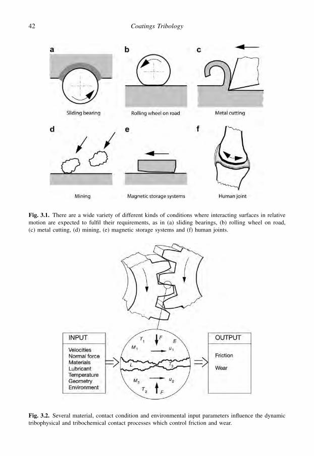
Fig. 3.1. There are a wide variety of different kinds of conditions where interacting surfaces in relativemotion are expected to fulfil their requirements, as in (a) sliding bearings, (b) rolling wheel on road,(c) metal cutting, (d) mining, (e) magnetic storage systems and (f) human joints.
Fig. 3.2. Several material, contact condition and environmental input parameters influence the dynamictribophysical and tribochemical contact processes which control friction and wear.
42 Coatings Tribology

usefulness in tribology have been discussed by Whitehouse (1974), Czichos (1978), Williamson(1984), O’Connor et al. (1991), Bhushan (1999b), and Cai and Bhushan (2007).
It has, however, been difficult to find a suitable parameter that would uniquely satisfy the need tocharacterize the surface roughness with respect to its influence on friction and wear. In lubricatedcontacts especially, there is also a need to take into account the topographical pattern, such as thedirection of grooves in the surface (Holmberg, 1984, 1989).
Tribological surfaces normally exhibit a random roughness profile across different length scalesand this is changing during the process of sliding contact. It is difficult to represent this by numericalmethods, as those in use today normally work well with surface data exhibiting a fixed random profileand provide surface descriptors closely related to a scale at which surface data were acquired. Acomparison of different methods such as Fourier transform, windowed Fourier transform, Cohen’sclass distributions, wavelet transform, fractal methods and hybrid-wavelet method was carried out byPodsiadlo and Stachowiak (2002). They concluded that the most suitable method for tribologicalsurfaces appears to be a hybrid fractal-wavelet method, i.e. a method in which a partition iteratedfunction system and a wavelet transform are combined.
When one surface is placed upon another, the first contact between the surfaces will take place atthe top points of the highest peaks of the surfaces. Two metallic surfaces that are pressed together havea real contact area which may be only about 10% of the surface area, as shown in Fig. 3.3c. Analysis ofgap-maps with a lightly bead-blasted glass surface suggests that normal contact is almost entirelyconfined to the highest 25% of each surface and mainly occurs in the top 10% (Williamson, 1984).
The chemical and physical nature of a surface depends on the composition of the material and thesurrounding environment. A schematic representation of a solid surface is shown in Fig. 3.4 (Bhushan,1999b). Finished mechanical components have a surface layer with properties different from the bulkmaterial depending on the machining process. Energy that goes to the near surface region duringmachining can result in deformation, strain hardening, recrystallization and texturing. In polishing,grinding, lapping and machining, the surface layers are plastically deformed with or without atemperature gradient. They become highly strained and residual stresses may be released or created. Adeformed layer may also be produced during the friction process. The typical thickness of thedeformed layer is 10–100 mm. The Beilby layer in metals and alloys is produced by melting andsurface flow during machining. The layer typically has an amorphous or microcrystalline structureand is 1–100 nm thick.
Metals and alloys react with oxygen in air and form oxide layers. In other environments they mayform nitrides, sulphides and chlorides. Polymers generally do not form an oxide layer. Iron can formthe following oxides: Fe2O3, Fe3O4 or FeO. Oxides present on an alloy surface depend upon theconcentration of alloying elements, the affinity of alloying elements for oxygen, the ability of oxygen
Fig. 3.3. The shape of a surface is characterized by (a) the surface topography and (b) the surface profile.For two surfaces in contact, the real area of contact, shown in (c), is considerably smaller than the apparentarea of contact.
43Tribology of Coatings
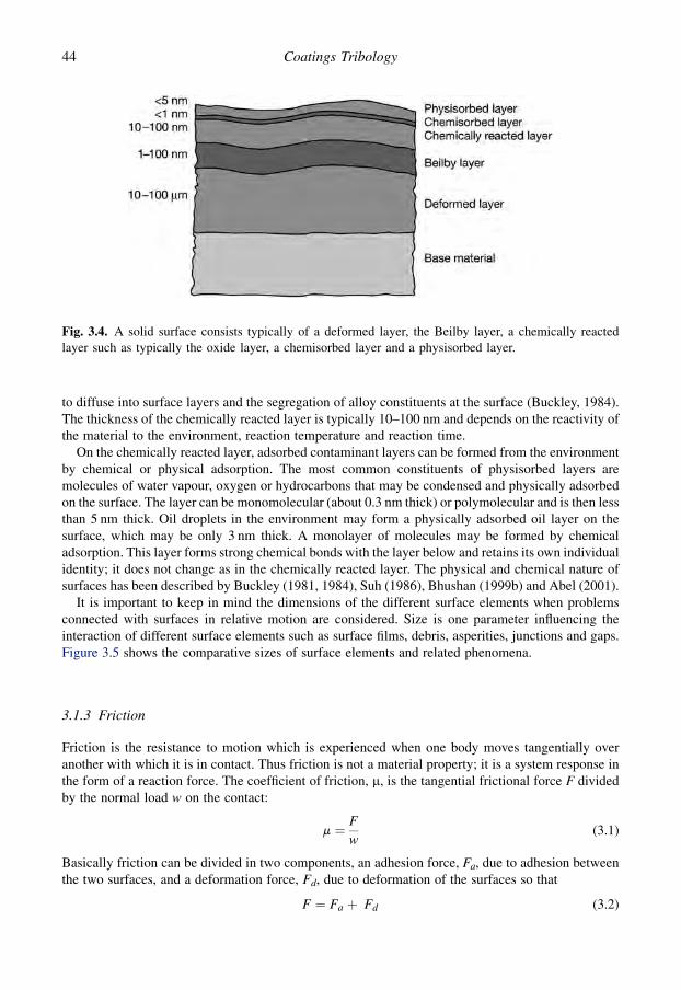
to diffuse into surface layers and the segregation of alloy constituents at the surface (Buckley, 1984).The thickness of the chemically reacted layer is typically 10–100 nm and depends on the reactivity ofthe material to the environment, reaction temperature and reaction time.
On the chemically reacted layer, adsorbed contaminant layers can be formed from the environmentby chemical or physical adsorption. The most common constituents of physisorbed layers aremolecules of water vapour, oxygen or hydrocarbons that may be condensed and physically adsorbedon the surface. The layer can be monomolecular (about 0.3 nm thick) or polymolecular and is then lessthan 5 nm thick. Oil droplets in the environment may form a physically adsorbed oil layer on thesurface, which may be only 3 nm thick. A monolayer of molecules may be formed by chemicaladsorption. This layer forms strong chemical bonds with the layer below and retains its own individualidentity; it does not change as in the chemically reacted layer. The physical and chemical nature ofsurfaces has been described by Buckley (1981, 1984), Suh (1986), Bhushan (1999b) and Abel (2001).
It is important to keep in mind the dimensions of the different surface elements when problemsconnected with surfaces in relative motion are considered. Size is one parameter influencing theinteraction of different surface elements such as surface films, debris, asperities, junctions and gaps.Figure 3.5 shows the comparative sizes of surface elements and related phenomena.
3.1.3 Friction
Friction is the resistance to motion which is experienced when one body moves tangentially overanother with which it is in contact. Thus friction is not a material property; it is a system response inthe form of a reaction force. The coefficient of friction, m, is the tangential frictional force F dividedby the normal load w on the contact:
m ¼ F
w(3.1)
Basically friction can be divided in two components, an adhesion force, Fa, due to adhesion betweenthe two surfaces, and a deformation force, Fd, due to deformation of the surfaces so that
F ¼ Fa þ Fd (3.2)
Fig. 3.4. A solid surface consists typically of a deformed layer, the Beilby layer, a chemically reactedlayer such as typically the oxide layer, a chemisorbed layer and a physisorbed layer.
44 Coatings Tribology

The deformation force is called ‘ploughing friction’ when it takes place on a macroscale and ‘asperitydeformation’ when it takes place on a microscale. In spite of its importance and after many centuriesof investigations and research there is still no complete physical explanation for friction.
3.1.3.1 Early friction theories
An excellent overview of the history of friction investigations has been presented by Dowson (1998).In the 20th century a new approach to friction was introduced by Bowden and Tabor (1950) andKragelsky (1957). They shifted the focus of models explaining friction from component andmacro-contact scales – such as apparent contact area and Hertz contact pressure – to phenomena ofmicrometre size. Surface topography, asperity collisions and molecular boundary layers now becameof particular interest.
Bowden and Tabor explained that when two asperities are forced into contact they will weldtogether due to the adhesion between the two materials as shown in Fig. 3.6a. When one of the solidsis moved in a tangential direction relative to the other the micro-welded junctions will break but theirshear strength causes a resistance to motion. During sliding, new micro-welded junctions are formedand broken continuously.
The adhesion model of friction was, however, criticized on the basis of several objections, such as:
� the agreement between the theoretically calculated and the experimentally obtained values of thecoefficient of friction is not particularly good,� the model does not take into account the surface roughness effect on friction,� there is a lack of evidence that the junctions produced will be of necessary strength, and� when the normal force pressing the surfaces together is removed the adhesion cannot be detected.
Fig. 3.5. Sizes of surface elements and surface-related phenomena.
45Tribology of Coatings

Bowden and Tabor (1950) also included the ploughing effect in their concept of friction. When a hardasperity or a hard particle penetrates into a softer material and ploughs out a groove by plastic flow inthe softer material this action creates a resistance to motion as shown in Fig. 3.6b. To overcome theshortcomings of the adhesion theory of friction Rabinowicz (1965) offered a theory according towhich the surface energy of adhesion as well as the roughness angle of the surface and the radius ofthe junctions is taken into account.
A molecular–mechanical theory of friction was developed by Kragelsky (1957, 1965). Here theword ‘molecular’, according to the Russian terminology, stands for the adhesion component andthe word ‘mechanical’ stands for the material deformation component. Kragelsky includes in theadhesion component a so-called piezo coefficient, which characterizes the increase of shear strengthwith compressive force, according to a binomial law introduced by Deryagin in 1934 (Kragelskyet al., 1982).
Some workers (reviewed by Rigney and Hirth, 1979) have concentrated more on the effectof plastic deformation losses in friction. The influence of plastic deformation of asperities wasconsidered by Green (1955) and extended by Edwards and Halling (1968). They showed that re-sistance to motion arises from the work done when asperities are plastically deformed as they slideover each other, as shown in Fig. 3.6c. On the basis of studies concentrating on plastic deformationlosses in the material, Heilmann and Rigney (1981) suggest an energy-based friction model wheremetallurgical effects are included. However, their results have been disputed by Tangena et al. (1984).In an analysis of the adhesion, deformation and surface roughness effects on friction Tangena (1987)concludes that if surface asperities are plastically deformed the influence of surface roughness on thecontact parameters will be small, because the asperities will deform in such a way that a continuoussurface is obtained. This is supported by Rabinowicz (1992) who found only a rather modest influenceof surface roughness on the coefficient of friction in static friction experiments with noble metals.A review of the classical friction theories can be found in Tabor (1981).
3.1.3.2 Genesis of friction at the microscale
A new concept of friction, called the genesis of friction, was presented by Suh and Sin (1981). Theyfocused on microscale friction mechanisms and showed that the mechanical properties affect thefrictional behaviour to a greater extent than chemical properties when sliding occurs without
Fig. 3.6. The three components of sliding friction are (a) adhesion, (b) ploughing and (c) asperitydeformation.
46 Coatings Tribology

a significant interfacial temperature rise. The effect of friction can be divided into three basicmechanisms, one due to asperity deformation, one due to adhesion and one due to particle ploughing,as shown in Fig. 3.6. The adhesion mechanism in many practical cases may not be the most dominantof the three. They also stress the influence of the history of sliding on the friction force. On the basis ofcrossed-cylinder experiments carried out with specimens made of engineering materials they give thefollowing typical values for the three components of the coefficient of friction (with maximum valuesin brackets):
1. Friction due to asperity deformation, md¼ 0–0.43 (0.75). It appears that asperity deformation isresponsible for the static coefficient of friction. Once the original asperities have been deformed,asperity interlocking cannot take place. This component can contribute to steady-state friction ifnew asperities are continuously generated as a result of the wear process.
2. Friction due to adhesion, ma¼ 0–0.4. The low value is for a well-lubricated surface. The high valueis for identical metals sliding against each other without any surface contamination or oxide layers.
3. Friction due to ploughing, mp¼ 0–0.4 (1.0). The low value is obtained either when wear particlesare totally absent from the interface or when a soft surface is slid against a hard surface witha mirror finish. The high value is associated with two identical metals sliding against each otherwith deep penetration by wear particles.
In a more detailed study of the microscopic mechanisms of friction Kim and Suh (1991) claim that theploughing component of the surfaces by wear particles is the most important in most sliding situa-tions. This is supported by a study by Miyoshi (2001) showing that there is no clear relationshipbetween the coefficient of friction and the theoretical shear strength. However, for most materialcombinations, with different metals sliding on themselves and on non-metals, friction increased as thetheoretical shear strength decreased. The relation between friction and the theoretical tensile strengthhad a similar behaviour.
In contradiction to this it can be argued that the lubrication of initially dry surfaces usually reducesfriction drastically. In a review on adhesion, friction and wear, Landheer and de Gee (1991) point outthat a boundary lubricant film only a few molecules thick, in the nanometre range, can effectivelyreduce friction, e.g. from 1.0 to 0.1, without affecting asperity interaction and thus the ploughingeffect. The influence of surface roughness on both the initial and the steady-state friction has beenfound to be considerable for sliding steel and ceramic pairs by Hwang and Zum Ghar (2003). Achange of the surface roughness from polished, Ra¼ 0.02 mm, steel plate to a ground one,Ra¼ 0.57 mm, sliding against a polished, Ra¼ 0.02 mm, steel ball resulted in a drop in the steady-statefriction of about 30%. When they introduced oil lubrication the initial friction dropped moderately, by0–10%, but the steady-state friction dropped considerably, by 10–60%.
Based on knowledge available on the mechanisms of friction in sliding contacts it seems thatboth the particle ploughing effect and the adhesion effect are important and either of them maydominate the frictional behaviour, depending on the tribological contact conditions. This certainlymeans that the effect of wear particle ploughing in friction should be given more consideration thanpreviously the case.
3.1.3.3 Development of friction with time
The chronological stage of a sliding contact influences considerably its frictional behaviour. Essen-tially, a contact starts with a running-in period followed by a steady-state period and ends bya breakdown or destruction period. From a practical point of view it is important to achieve a con-trolled running-in period resulting in optimal frictional behaviour during the steady-state period. Thesteady-state period represents the major part of the lifetime of the contact.
A sliding contact goes through several stages of different friction mechanisms in the running-inperiod before the steady-state period is reached. Suh and Sin (1981) identified five different friction
47Tribology of Coatings

stages that occurred in steel contacts before steady-state friction. These stages are specific for thematerials tested, the experimental arrangement and the environmental conditions. However, as anexample of the mechanisms they are very illuminating. The different stages are shown in Fig. 3.7 andare as follows:
Stage 1. Initially, the friction force is largely a result of ploughing of the surface by asperities. Ad-hesion does not play any significant role due to surface contamination. Asperity deformation takesplace and affects the static coefficient of friction and the surface is easily polished. Consequently, thecoefficient of friction in the initial stage is largely independent of material combinations, surfaceconditions and environmental conditions.
Stage 2. The polishing wear process at stage 1 has removed surface contamination and elements ofbare surface will appear, resulting in a slow increase in the coefficient of friction due to increasedadhesion.
Stage 3. The coefficient of friction increases due to a rapid increase in the number of wear particlesentrapped between the sliding surfaces as a consequence of higher wear rates. The deformation ofasperities continues and the adhesion effect increases due to larger clean interfacial areas. Some of thewear particles are trapped between the surfaces, causing ploughing. If the wear particles are entrappedbetween metals of equal hardness they will penetrate into both surfaces, preventing any slippagebetween the particle and the surface and resulting in maximum ploughing friction.
Stage 4. The number of wear particles entrapped between the surfaces remains constant because thenumber of entrapped particles entering is the same as the number leaving the interface. The adhesioncontribution also remains constant and the asperity deformation continues to contribute, since thewear by delamination creates new rough surfaces with asperities. Stage 4 represents the steady-statefriction when two identical materials slide against each other or when the mechanisms of stage 5 arenot significant.
Stage 5. In some cases, such as when a very hard stationary slider is slid against a soft specimen, theasperities of the hard surface are gradually removed, creating a mirror-like smooth surface. Thefrictional force decreases, due to the decrease in asperity deformation and ploughing, because wearparticles cannot anchor so easily to a polished surface.
Stage 6. The coefficient of friction slowly levels off and reaches a steady-state value as the hardsurface becomes mirror smooth to a maximum extent and the softer surface also acquires a mirrorfinish.
Fig. 3.7. Six stages of friction mechanisms occurring in sliding steel contacts in the initial period ofsliding (after Suh and Sin, 1981).
48 Coatings Tribology

3.1.3.4 Influence of wear debris and layers
The above stages of initial friction are representative for the combinations of steel materials studied bySuh and Sin (1981) and the experimental conditions used. They will be different in other cases, forexample in contacts where transfer layers are formed, and the interfacial friction is then causedprimarily by the combined effect of the three basic mechanisms of friction (Blau, 1989). The influenceof metal transfer in sliding friction was studied by Landheer and Zaat (1974) and they showed that themetal transfer layers always occur according to the same fundamental process; there is only a dif-ference in scale, at which the process presents itself.
The important but often neglected influence of wear particles in a sliding contact has been shownfor steel contacts in crossed-cylinder experiments with 10 N normal load, 0.02 m/s sliding speed and6.35 mm sample diameter. After a running-in period the experiment was stopped and the wear par-ticles were removed, which resulted in a decrease in the coefficient of friction from 0.71 to 0.4 asshown in Fig. 3.8. The initial coefficient of friction was 0.13. New direct evidence of the wear debrisand wear layer influence on friction in sliding contacts was demonstrated by Singer et al. (2003). Themechanisms of wear debris generation, agglomeration, mechanical mixing and formation of reactionand transfer layers is discussed in sections 3.3.7–3.3.9.
3.1.3.5 Friction equations
During recent years there have been numerous attempts to formulate mathematical expressions for thefriction force or the coefficient of friction (Dunayevsky, 1997; Bhushan, 1999b; Andersson, 2004). Allthese equations suffer from a lack of generality. They are limited to certain frictional mechanisms,material combinations or contact conditions and thus have not been very suitable for use in practicalapplications.
Two basic laws of friction are generally valid over a wide range of applications. They are oftenreferred to as Amonton’s laws and have recently been shown to work surprisingly well at themacroscale, microscale and even on the nanoscale (Gao et al., 2004; Tysoe and Spencer, 2004).The first states that there is a linear relationship between the friction force and the normal load.This means that the coefficient of friction, m, is a constant independent of the normal load (seeequation 3.1).
Fig. 3.8. Effect of removing wear particles from a crossed-cylinder contact with steel sliding on steel(after Suh and Sin, 1981).
49Tribology of Coatings

The second law states that the friction force or the coefficient of friction is independent of theapparent area of contact between the contacting bodies (see Fig. 3.3c). Thus the physical size does notinfluence the coefficient of friction.
A third law is sometimes linked to these two. It states that the friction force is independent of thesliding velocity. The applicability of this third law is much more limited. These three laws are entirelybased on empirical observations.
Based on recent understanding of friction mechanisms there has been, however, important workpublished in the direction of a more general friction equation. One such example is the model forfriction of two elastoplastic surfaces in quasi-steady-state sliding by Zhang et al. (1991a). The modelconsiders the separate effects of asperity interaction and deformation, debris interaction andploughing, and adhesion, with partitioning of normal load and contact areas between differentcontacting elements. It illustrates well the complexity of describing the contacting system and itsrelation to friction. The analysis is restricted to nominally steady-state sliding where the contactparameters are statistically invariant. The authors use the word ‘quasi’ to emphasize that in tribo-dynamic systems there is no true equilibrium condition in which the frictional effects are constant.
The coefficient of friction, m, can, according to the Zhang et al. (1991a) model, be formulated as:
m ¼ S1
w
hð1� bÞ Aa $ f
�sa1
1S1
�þ b $ Aa þ Ad1
iþ S2
w
hð1� bÞ Aa $ f
�sa2
1S2
�þ b Aa $ f
�S1 $ H1
S2 $ H2
�þ Ad2
i(3.3)
and
f ðtÞ ¼ 1 � 2ln ð1 þ tÞ � t
ln ð1 � t2Þ (3.4)
where Si is the shear strength of the contacting material (Pa), w is the applied normal load (N), b is thepercentage of asperity contact area under compression, Aa is the contact area contributed by deformedasperities (m2), sai is the shear stress within the asperity adhesion area of the material, Adi is the totaldebris contact area (m2), Hi is the hardness of the contacting material (Pa) and t0 is a dummy variable.
The model has been compared with experimental measurements (Zhang et al., 1991b) with theconclusion that it can predict the coefficient of friction with reasonable accuracy. According to themodel, adhesive effects are negligible. To enable the use of the formula, estimations must be made foraverage debris diameter, debris density and percentage of debris ploughing in the softer material andasperity adhesive and ploughing contributions.
In the case of macroploughing, using the example of a rigid spherical ball penetrating a softersurface and moving tangentially forming a groove, the ploughing component can be derived directlyby calculating the volume of deformed material. The adhesive component consists of a material strainconstant and the geometrically derived surface of sliding. The equations are derived in Komvopoulos(1991b), Bhushan (1999b), Lafaye et al. (2005) and Felder and Bucaille (2006).
3.1.3.6 Atomic scale friction
Friction at the microscale is a result of breaking bonds between individual atoms, whether instigatedby strong adhesion or by micro-asperity interlocking, and slip along the crystal planes in the presenceof defects. Breakage of cohesive bonds will occur during microplastic deformation or fracture.Depending on the relative strengths of the interfacial and cohesive bonds of the solids, breakage of thebonds will occur at locations that offer the least resistance to sliding (Kim and Suh, 1991).
Emerging techniques such as atomic force microscopy and other surface analysis methods(Israelachvili and Tabor, 1972; Bhushan, 1999b) have opened a new possibility to study friction and
50 Coatings Tribology
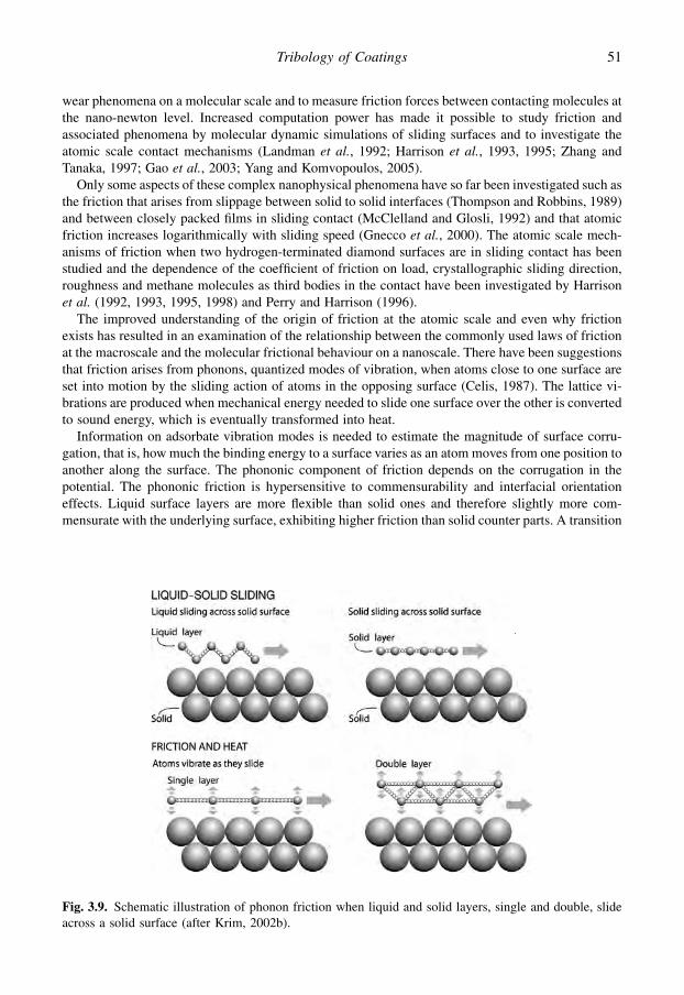
wear phenomena on a molecular scale and to measure friction forces between contacting molecules atthe nano-newton level. Increased computation power has made it possible to study friction andassociated phenomena by molecular dynamic simulations of sliding surfaces and to investigate theatomic scale contact mechanisms (Landman et al., 1992; Harrison et al., 1993, 1995; Zhang andTanaka, 1997; Gao et al., 2003; Yang and Komvopoulos, 2005).
Only some aspects of these complex nanophysical phenomena have so far been investigated such asthe friction that arises from slippage between solid to solid interfaces (Thompson and Robbins, 1989)and between closely packed films in sliding contact (McClelland and Glosli, 1992) and that atomicfriction increases logarithmically with sliding speed (Gnecco et al., 2000). The atomic scale mech-anisms of friction when two hydrogen-terminated diamond surfaces are in sliding contact has beenstudied and the dependence of the coefficient of friction on load, crystallographic sliding direction,roughness and methane molecules as third bodies in the contact have been investigated by Harrisonet al. (1992, 1993, 1995, 1998) and Perry and Harrison (1996).
The improved understanding of the origin of friction at the atomic scale and even why frictionexists has resulted in an examination of the relationship between the commonly used laws of frictionat the macroscale and the molecular frictional behaviour on a nanoscale. There have been suggestionsthat friction arises from phonons, quantized modes of vibration, when atoms close to one surface areset into motion by the sliding action of atoms in the opposing surface (Celis, 1987). The lattice vi-brations are produced when mechanical energy needed to slide one surface over the other is convertedto sound energy, which is eventually transformed into heat.
Information on adsorbate vibration modes is needed to estimate the magnitude of surface corru-gation, that is, how much the binding energy to a surface varies as an atom moves from one position toanother along the surface. The phononic component of friction depends on the corrugation in thepotential. The phononic friction is hypersensitive to commensurability and interfacial orientationeffects. Liquid surface layers are more flexible than solid ones and therefore slightly more com-mensurate with the underlying surface, exhibiting higher friction than solid counter parts. A transition
Fig. 3.9. Schematic illustration of phonon friction when liquid and solid layers, single and double, slideacross a solid surface (after Krim, 2002b).
51Tribology of Coatings
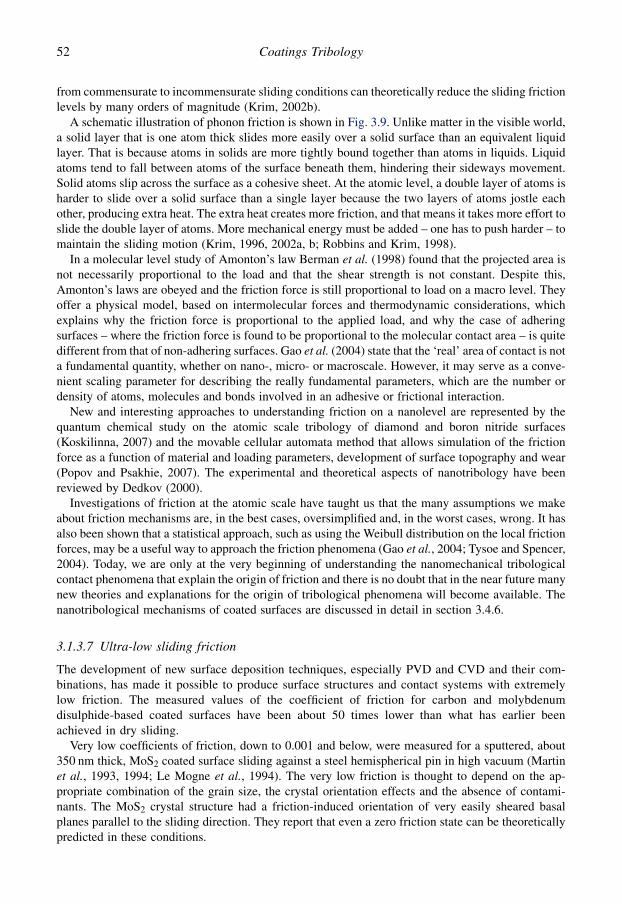
from commensurate to incommensurate sliding conditions can theoretically reduce the sliding frictionlevels by many orders of magnitude (Krim, 2002b).
A schematic illustration of phonon friction is shown in Fig. 3.9. Unlike matter in the visible world,a solid layer that is one atom thick slides more easily over a solid surface than an equivalent liquidlayer. That is because atoms in solids are more tightly bound together than atoms in liquids. Liquidatoms tend to fall between atoms of the surface beneath them, hindering their sideways movement.Solid atoms slip across the surface as a cohesive sheet. At the atomic level, a double layer of atoms isharder to slide over a solid surface than a single layer because the two layers of atoms jostle eachother, producing extra heat. The extra heat creates more friction, and that means it takes more effort toslide the double layer of atoms. More mechanical energy must be added – one has to push harder – tomaintain the sliding motion (Krim, 1996, 2002a, b; Robbins and Krim, 1998).
In a molecular level study of Amonton’s law Berman et al. (1998) found that the projected area isnot necessarily proportional to the load and that the shear strength is not constant. Despite this,Amonton’s laws are obeyed and the friction force is still proportional to load on a macro level. Theyoffer a physical model, based on intermolecular forces and thermodynamic considerations, whichexplains why the friction force is proportional to the applied load, and why the case of adheringsurfaces – where the friction force is found to be proportional to the molecular contact area – is quitedifferent from that of non-adhering surfaces. Gao et al. (2004) state that the ‘real’ area of contact is nota fundamental quantity, whether on nano-, micro- or macroscale. However, it may serve as a conve-nient scaling parameter for describing the really fundamental parameters, which are the number ordensity of atoms, molecules and bonds involved in an adhesive or frictional interaction.
New and interesting approaches to understanding friction on a nanolevel are represented by thequantum chemical study on the atomic scale tribology of diamond and boron nitride surfaces(Koskilinna, 2007) and the movable cellular automata method that allows simulation of the frictionforce as a function of material and loading parameters, development of surface topography and wear(Popov and Psakhie, 2007). The experimental and theoretical aspects of nanotribology have beenreviewed by Dedkov (2000).
Investigations of friction at the atomic scale have taught us that the many assumptions we makeabout friction mechanisms are, in the best cases, oversimplified and, in the worst cases, wrong. It hasalso been shown that a statistical approach, such as using the Weibull distribution on the local frictionforces, may be a useful way to approach the friction phenomena (Gao et al., 2004; Tysoe and Spencer,2004). Today, we are only at the very beginning of understanding the nanomechanical tribologicalcontact phenomena that explain the origin of friction and there is no doubt that in the near future manynew theories and explanations for the origin of tribological phenomena will become available. Thenanotribological mechanisms of coated surfaces are discussed in detail in section 3.4.6.
3.1.3.7 Ultra-low sliding friction
The development of new surface deposition techniques, especially PVD and CVD and their com-binations, has made it possible to produce surface structures and contact systems with extremelylow friction. The measured values of the coefficient of friction for carbon and molybdenumdisulphide-based coated surfaces have been about 50 times lower than what has earlier beenachieved in dry sliding.
Very low coefficients of friction, down to 0.001 and below, were measured for a sputtered, about350 nm thick, MoS2 coated surface sliding against a steel hemispherical pin in high vacuum (Martinet al., 1993, 1994; Le Mogne et al., 1994). The very low friction is thought to depend on the ap-propriate combination of the grain size, the crystal orientation effects and the absence of contami-nants. The MoS2 crystal structure had a friction-induced orientation of very easily sheared basalplanes parallel to the sliding direction. They report that even a zero friction state can be theoreticallypredicted in these conditions.
52 Coatings Tribology

Low coefficients of friction of the same level, down to 0.001, have been measured by Erdemir et al.(2000, 2001) for a 1 mm thick diamond-like carbon coating deposited on a flat sapphire surface slidingagainst a similarly coated sapphire ball in inert-gas environments such as dry nitrogen and argon. Thesurfaces were extremely smooth so asperity interlocking effects were eliminated; the surfaces werehard so ploughing effects were eliminated; and the dangling bonds of the carbon structure wereattached to hydrogen atoms creating inert hydrophobic surfaces that exhibit almost no frictionalresistance (Harrison et al., 1995; Erdemir, 2002). Actually, no internal material shear is taking place atall, the hydrogen planes just ‘fly’ over each other.
The above ultra-low friction experiments were carried out in special environments, in highvacuum or in an inert gas. However, low friction values have also been measured in normal airrecently. Abreu et al. (2005) measured a coefficient of friction of 0.03 for a CVD diamond coatedsurface sliding against a similarly coated ball in normal air. Vander Wal et al. (2005) have reportedextremely low coefficients of friction, between 0.002 and 0.07, for a quartz disk that was carbonnanotube surface-fluorinated and sliding in contact with a sapphire ball in air of about 40% relativehumidity and room temperature.
The property of two surfaces sliding over each other with extremely low friction is also referredto as ‘superlubricity’. Erdemir and Martin (2007) present studies of superlubricity related to thetheoretical aspects, various sliding systems at nanoscale, lamellar solids over a broad range of scales,carbon-based thin coatings at macroscale and superlubricity in elastohydrodynamic and boundarylubrication regimes.
3.1.3.8 Rolling friction
We have so far considered friction mechanisms only in relation to the sliding of one surface overanother. In the case of rolling, the coefficient of friction is normally smaller. The general consider-ations in relation to contact mechanisms are also valid for rolling contacts, but, because of thedifference in contact kinematics, other contact effects dominate the frictional behaviour.
The main contributions to friction in rolling contacts are:
� micro-slip effects within the contact area,� elastic hysteresis of the contacting materials,� plastic deformation of the materials, and� adhesion effects in the contact.
The contact mechanics for rolling are certainly complex but fairly well understood on a macroscopiclevel (Halling, 1975; Czichos, 1978; Johnson, 1985; Bhushan, 1999b). On the microscopic level theyare less well understood, but on this level the mechanisms of contact physics and chemistry dominateand they are mainly similar to the mechanisms in sliding contacts discussed in more detail earlier.
3.1.3.9 Typical values for the coefficient of friction
The coefficient of friction depends on the contact system. It can vary a great deal with regard to thematerial pair used. Some typical values for the coefficient of friction in sliding contacts are given inTable 3.1.
3.1.4 Wear
Wear is commonly defined as the removal of material from solid surfaces as a result of one contactingsurface moving over another. Thus both friction and wear are simultaneously the results of the sametribological contact process that takes place between two moving surfaces. However, their in-terrelationship is not well understood. It is common to find that low friction corresponds to low wear
53Tribology of Coatings

and high friction to high wear, as shown in the set of experimental results in Fig. 3.10 by Saka (1980).However, this is not a general rule and there are several examples (e.g. Franklin, 1991) of contra-dictory behaviour. The figure also illustrates another typical feature. The value for the wear coefficientmay well change, in different conditions, by several orders of magnitude. This can be contrasted withthe coefficient of friction, which rarely changes by more than a single order of magnitude, unlessa lubricant is introduced or removed from a contact – and in that case the wear would show evengreater changes.
A wear mechanism is a classification of the process by which material is removed from the contactsurface. Typical wear mechanisms are adhesive, abrasive, fatigue and chemical wear. It is verycommon that in a real contact more than one wear mechanism is acting at the same time (Holmberg,1991). The precise combination of wear mechanisms depends on the contact conditions and will resultin a specific type of wear.
A wear mode is a classification of the type of contact, which is characterized by a specific kindof movement, geometry or environment. Examples of wear modes are sliding wear, rolling wear,
Table 3.1. Values for the coefficient of friction in dry sliding contacts. Some indicative values for thecoefficient of friction in different dry sliding systems are given below (data from Dowson, 1998;Avallone and Baumeister, 1987; Hutchings, 1992; Bhushan, 1999b).
Sliding materials coefficient of friction
Gold on gold 1–2Iron on iron 0.8–1.5Aluminium on aluminium 0.8–1.2Copper on copper 0.8–1.2Silver on silver 0.8–1Grey cast iron on grey cast iron 0.8–1Mild steel on mild steel 0.7–0.9Copper on mild steel 0.6–0.7Titanium on titanium 0.5–0.6Aluminium on mild steel 0.5–0.6Silver on steel 0.5Brake materials 0.5Titanium on mild steel 0.4–0.6Gold on mild steel 0.4–0.5Sandstone on sandstone 0.35Titanium carbide on titanium carbide 0.3–0.7Aluminium oxide on aluminium oxide 0.3–0.6Granite on granite 0.3Rubber on steel 0.3–3Titanium nitride on titanium nitride 0.25–0.5Leather on iron 0.25Polyimide on hard surface 0.2–0.4Polyamide (nylon) on hard surface 0.15–0.3Hardwood on hardwood 0.15Diamond on diamond 0.1–0.2Dry sliding in general 0.1 to 1.0Graphite solid lubricant on hard surface 0.05–0.15PTFE (teflon) on hard surface 0.05–0.1MoS2 solid lubricant on hard surface 0.05–0.1Fullerenes (c60) on hard surface 0.05–0.1Rolling friction (balls or rollers) 0.001–0.01DLC on DLC in dry nitrogen or argon 0.001–0.01MoS2 coated surface on steel in high vacuum 0.001 and below
54 Coatings Tribology
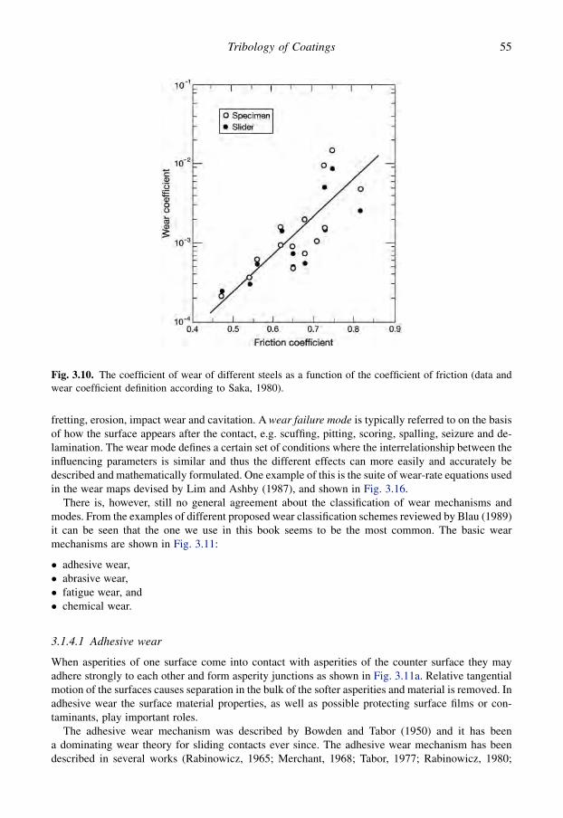
fretting, erosion, impact wear and cavitation. A wear failure mode is typically referred to on the basisof how the surface appears after the contact, e.g. scuffing, pitting, scoring, spalling, seizure and de-lamination. The wear mode defines a certain set of conditions where the interrelationship between theinfluencing parameters is similar and thus the different effects can more easily and accurately bedescribed and mathematically formulated. One example of this is the suite of wear-rate equations usedin the wear maps devised by Lim and Ashby (1987), and shown in Fig. 3.16.
There is, however, still no general agreement about the classification of wear mechanisms andmodes. From the examples of different proposed wear classification schemes reviewed by Blau (1989)it can be seen that the one we use in this book seems to be the most common. The basic wearmechanisms are shown in Fig. 3.11:
� adhesive wear,� abrasive wear,� fatigue wear, and� chemical wear.
3.1.4.1 Adhesive wear
When asperities of one surface come into contact with asperities of the counter surface they mayadhere strongly to each other and form asperity junctions as shown in Fig. 3.11a. Relative tangentialmotion of the surfaces causes separation in the bulk of the softer asperities and material is removed. Inadhesive wear the surface material properties, as well as possible protecting surface films or con-taminants, play important roles.
The adhesive wear mechanism was described by Bowden and Tabor (1950) and it has beena dominating wear theory for sliding contacts ever since. The adhesive wear mechanism has beendescribed in several works (Rabinowicz, 1965; Merchant, 1968; Tabor, 1977; Rabinowicz, 1980;
Fig. 3.10. The coefficient of wear of different steels as a function of the coefficient of friction (data andwear coefficient definition according to Saka, 1980).
55Tribology of Coatings

Buckley, 1981; Kragelskii, 1982; Landheer and de Gee, 1991; Bayer, 1994; Bhushan, 1999b; Katoand Adachi, 2001b; Stachowiak and Batchelor, 2005). The adhesion wear theory has, however, beencriticized (e.g. Jahanmir, 1980) on the following grounds:
� because of impurities it seems unlikely that the interface will be stronger than either of the bulkmaterials,� it cannot explain the wear of the harder surface which is frequently observed,� it cannot explain observed effects of surface roughness,� it cannot explain the creation of loose wear particles,� the maximum work required to generate wear particles is two to three orders of magnitude smaller
than the external work done,� it cannot explain the relation between friction and wear, and� it does not take into account microstructure and metallurgical parameters.
There is, though, enough experimental evidence in the references given above to prove that adhesivewear does occur in many sliding situations. However, based on analyses by Suh (1973), Jahanmir(1980) and Suh (1986) of friction and wear mechanisms, it seems that the adhesion wear mechanism
Fig. 3.11. The basic mechanisms of wear are (a) adhesive, (b) abrasive, (c) fatigue and (d) chemical wear.
56 Coatings Tribology

does not necessarily play such a dominating role in real contacts as had traditionally been considered.There are, however, conditions like sliding wear in vacuum or inert atmospheres, or when an asperityflash temperature is large enough to promote asperity adhesion, in which the effect of adhesive wearis likely to be the dominating mechanism. The influence of humidity has been observed to beconsiderable in dry sliding of steel against steel in normal air while the friction behaviour is lessaffected (Klafke, 2004a; Klafke et al., 2004b). In failure modes like scuffing and seizure the effect ofadhesive wear is very important.
3.1.4.2 Abrasive wear and asperity deformation
Wear by plastic deformation takes place both in abrasive wear and during asperity deformation asshown in Fig. 3.11b.
Abrasive wear occurs in contacts where one of the surfaces is considerably harder than the other orwhere hard particles are introduced into the contact. The harder surface asperities are pressed into thesofter surface which results in plastic flow of the softer material around the hard one. When the hardersurface moves tangentially, ploughing and removal of softer material takes place resulting in groovesor scratches in the surface.
Depending on the geometry of the harder surface and the degree of penetration, the removal ofmaterial can take different forms, such as ploughing, wedge formation or cutting, as shown byHokkirigawa and Kato (1988a, b). Ploughing abrasive wear is present to a large extent in mining andearth moving equipments. Wear modes such as gouging abrasion, grinding abrasion and erosionabrasion can be distinguished (Czichos, 1978). The action of metal cutting has been described asabrasive wear on a large scale.
A distinction is often made between two-body and three-body abrasive wear, where the latter refersto situations in which hard particles are introduced between the moving surfaces. The mechanism ofabrasive wear has been extensively studied, and described by several authors (Kruschov, 1974; Moore,1974; Sin et al., 1979; Zum Gahr, 1989; Hutchings, 1992; Kato, 1992; Bayer, 1994; Bhushan, 1999b;Kato and Adachi, 2001b; Adachi and Hutchings, 2003; Stachowiak and Batchelor, 2005; Atkins andLiu, 2007; Siniawski et al., 2007).
Asperity deformation is due to the roughness and waviness of the contacting surfaces. A collisionof two asperities results in plastic deformation of one or both of the asperities leading to materialremoval from the asperities. The asperity deformation mechanisms have been studied in detail by Suh(1986) and it seems possible that a large proportion of the wear effects earlier considered as adhesivehave in fact been processes of asperity deformation.
Sliding contacts deforming the surface plastically cause large plastic strains and strain hardening inthe surface. The plastic deformation changes the near-surface microstructure in ways which make thematerial resistant to local shear. This leads to the transfer of pieces of material and elements from theenvironment to produce an ultra-fine-grained transfer film. The very fine microstructure in thistransfer material is stabilized by the mixing in, actually a form of mechanical alloying, of a secondphase (Rigney et al., 1984).
Mechanical intermixing as a result of asperity deformation can also change the chemical com-position of the near-surface volume. The depth profile in Fig 3.12 shows the change in chemicalcomposition of a grey cast iron surface before and after oil lubricated sliding against a steel pin ata pressure of less than 100 MPa (Scherge et al., 2003a). The modified zone here exhibits an extensionof more than 150 nm. The distributions of calcium, oxygen and sodium have their maxima underneaththe surface, clearly indicating mechanical mixing.
3.1.4.3 Fatigue and delamination wear
Fatigue crack growth is now a well-documented phenomenon which results from loading andunloading of a surface, at a stress level in the material that it can sustain once but not if repeated many
57Tribology of Coatings

times. Fatigue can form the origin for large-scale cracking and liberation of surface material to formwear debris as shown in Fig. 3.11c.
Classic surface fatigue wear is a lifetime limiting failure mechanism in ball and roller bearings andin gear contacts. In these concentrated contacts the Hertzian pressure at the surface creates a stressfield beneath the contact zone. The maximum shear stress occurs about one-third of the contact lengthbeneath the surface in the case of pure rolling and moves to the surface with increasing traction. Forcoefficients of friction exceeding 0.32 the maximum shear stress will be found on the surface, asshown in Fig. 3.13 (Schouten, 1973a, b).
In rolling, where the stress field moves repeatedly over the surface, fatigue of the near-surfacematerial takes place. Material voids or dislocation pile-ups may form the nuclei for the first crack tooccur. After that the crack will often propagate quite rapidly, unite with other cracks and liberatesurface material. This often results in large craters in the surface with diameters of 1 to 2 millimetresand rapid destruction of the whole surface. The mechanism of rolling contact fatigue is not fullyunderstood even though it has been extensively studied (Lundberg and Palmgren, 1947, 1952; Tallian,1967–68, 1982; Tallian and McCool, 1971; Scott, 1979; Bamberger and Clark, 1982; Sundquist,1981; Spikes et al., 1986; Longching et al., 1989; Bayer, 1994; Ding et al., 1996; Zaretsky, 1997;Murakami et al., 1997; Ioannides et al., 1999). Effects of lubricant film thickness and chemistry onfatigue life and crack propagation have been observed but are also not fully understood (Fowles et al.,1981; Cantley, 1983; Sullivan and Middleton, 1989). Pitting and spalling are wear failure modes inwhich the fatigue wear mechanism dominates.
Fig. 3.12. Depth profile by Auger electron spectroscopy of grey cast iron: (a) the initial state and (b) wornstate after 200 hours of sliding (after Scherge et al., 2003a).
58 Coatings Tribology
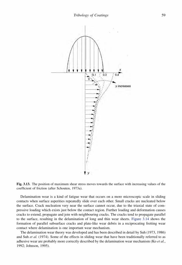
Delamination wear is a kind of fatigue wear that occurs on a more microscopic scale in slidingcontacts when surface asperities repeatedly slide over each other. Small cracks are nucleated belowthe surface. Crack nucleation very near the surface cannot occur, due to the triaxial state of com-pressive loading which exists just below the contact region. Further loading and deformation causescracks to extend, propagate and join with neighbouring cracks. The cracks tend to propagate parallelto the surface, resulting in the delamination of long and thin wear sheets. Figure 3.14 shows theformation of parallel subsurface cracks and plate-like wear debris in a reciprocating fretting wearcontact where delamination is one important wear mechanism.
The delamination wear theory was developed and has been described in detail by Suh (1973, 1986)and Suh et al. (1974). Some of the effects in sliding wear that have been traditionally referred to asadhesive wear are probably more correctly described by the delamination wear mechanism (Ko et al.,1992; Johnson, 1995).
Fig. 3.13. The position of maximum shear stress moves towards the surface with increasing values of thecoefficient of friction (after Schouten, 1973a).
59Tribology of Coatings
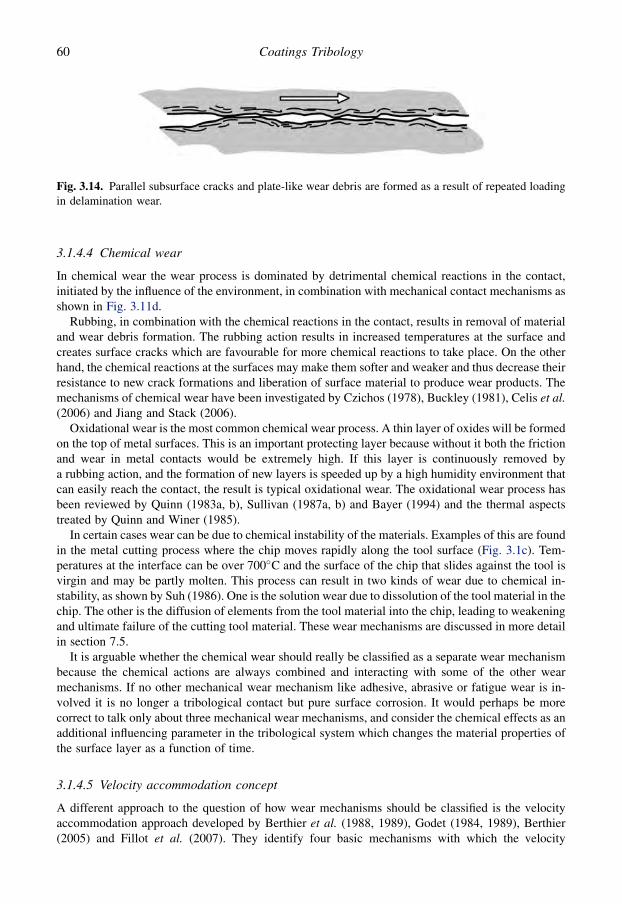
3.1.4.4 Chemical wear
In chemical wear the wear process is dominated by detrimental chemical reactions in the contact,initiated by the influence of the environment, in combination with mechanical contact mechanisms asshown in Fig. 3.11d.
Rubbing, in combination with the chemical reactions in the contact, results in removal of materialand wear debris formation. The rubbing action results in increased temperatures at the surface andcreates surface cracks which are favourable for more chemical reactions to take place. On the otherhand, the chemical reactions at the surfaces may make them softer and weaker and thus decrease theirresistance to new crack formations and liberation of surface material to produce wear products. Themechanisms of chemical wear have been investigated by Czichos (1978), Buckley (1981), Celis et al.(2006) and Jiang and Stack (2006).
Oxidational wear is the most common chemical wear process. A thin layer of oxides will be formedon the top of metal surfaces. This is an important protecting layer because without it both the frictionand wear in metal contacts would be extremely high. If this layer is continuously removed bya rubbing action, and the formation of new layers is speeded up by a high humidity environment thatcan easily reach the contact, the result is typical oxidational wear. The oxidational wear process hasbeen reviewed by Quinn (1983a, b), Sullivan (1987a, b) and Bayer (1994) and the thermal aspectstreated by Quinn and Winer (1985).
In certain cases wear can be due to chemical instability of the materials. Examples of this are foundin the metal cutting process where the chip moves rapidly along the tool surface (Fig. 3.1c). Tem-peratures at the interface can be over 700�C and the surface of the chip that slides against the tool isvirgin and may be partly molten. This process can result in two kinds of wear due to chemical in-stability, as shown by Suh (1986). One is the solution wear due to dissolution of the tool material in thechip. The other is the diffusion of elements from the tool material into the chip, leading to weakeningand ultimate failure of the cutting tool material. These wear mechanisms are discussed in more detailin section 7.5.
It is arguable whether the chemical wear should really be classified as a separate wear mechanismbecause the chemical actions are always combined and interacting with some of the other wearmechanisms. If no other mechanical wear mechanism like adhesive, abrasive or fatigue wear is in-volved it is no longer a tribological contact but pure surface corrosion. It would perhaps be morecorrect to talk only about three mechanical wear mechanisms, and consider the chemical effects as anadditional influencing parameter in the tribological system which changes the material properties ofthe surface layer as a function of time.
3.1.4.5 Velocity accommodation concept
A different approach to the question of how wear mechanisms should be classified is the velocityaccommodation approach developed by Berthier et al. (1988, 1989), Godet (1984, 1989), Berthier(2005) and Fillot et al. (2007). They identify four basic mechanisms with which the velocity
Fig. 3.14. Parallel subsurface cracks and plate-like wear debris are formed as a result of repeated loadingin delamination wear.
60 Coatings Tribology

difference between two surfaces in relative motion can be accommodated; elastic deformation,fracture, shear and rolling. These basic mechanisms may occur in either of the two surfaces (firstbodies) or in the layer between them (third body), as shown in Fig. 3.15. The major advantage withthis approach is that the fundamental tribological mechanisms are simplified to well-known mech-anisms of material behaviour that can be characterized by properties such as Young’s modulus,fracture toughness and shear strength. It is, however, clear that much work has to be done before thesebasic properties can be combined in an adequate and useful way to form a model that representsfriction and wear behaviour in real contacts. New modelling techniques as well as increased com-putation capacity offer an improved possibility to determine the tribological behaviour in a contactbased on the basic material performance specifications of the contacting surfaces (Holmberg et al.,2003, 2006a, b; Laukkanen et al., 2006).
3.1.4.6 Wear failure modes or types of wear
The wear failure mode or type of wear describes a certain combination of wear mechanism witha well-described regular process of material removal that corresponds to a particular range of contactconditions. The most common wear failure modes are:
� fretting,� pitting,� scuffing,� gouging,� electrical wear,� solution wear,� melt wear,� spalling,� scoring,� galling,� cavitation,
Fig. 3.15. The mechanisms of velocity accommodation of two surfaces in relative motion (after Godet,1989).
61Tribology of Coatings
� diffusive wear,� mild wear and� severe wear.
The published work on wear failure modes is largely descriptive with little analytical basis. Differentmodes have been described and reviewed, e.g., by Moore (1975), Jahanmir (1980), Peterson andWiner (1980), Blau (1989), Kato (2002) and Cartier (2003). The whole subject is still in a somewhatconfused state because much work is published but with non-comparable data because of the largevariations in test conditions and equipment. There is still no adequate description of the in-terrelationship between the different wear failure modes or the transition regimes and mechanisms oftransfer from one mode to another. Pioneering efforts to try to cover this complex and most difficultfield are found in the works of Lim and Ashby (1987), Blau (1989), Kitsunai et al. (1990), Kato (1992)and Kato and Adachi (2001b).
3.1.4.7 Wear equations
Because of the complexity of the wear process, which depends on materials, contact conditions andenvironmental parameters in a number of different combinations, it has not been possible to formulatea universal equation of wear. Numerous authors (reviewed by Bahadur, 1978; Meng and Ludema,1995; Dunaevsky, 1997; Bhushan, 1999b) have developed wear equations for the different wearmodes but all of them are quite limited in their range of validity. Meng and Ludema (1995) listed 100different variables and constants they found in the equations for general sliding wear, which illustrateswell the complexity of the wear process. The Russian school originating from Kragelsky has thelongest tradition and experience in formulating wear equations for different kinds of contact condi-tions and machine components (Kragelsky, 1965; Kragelsky et al., 1982; and Kragelskii andMarchenko, 1982).
A more general approach is taken by Lim and Ashby (1987) in which they show the validity rangesof six different wear modes in a wear map with normalized contact pressure and normalized velocityas coordinates and also give wear equations for each wear mode. The identified wear modes are ultra-mild wear, delamination wear, mild oxidational wear, severe oxidational wear, melt wear and seizure.The representation is, however, limited to a steel sliding pair in a pin-on-disk machine as shown inFig. 3.16.
It is possible to observe some common features when studying the proposed wear equations for thedifferent wear modes. Often the worn volume is directly proportional to the normal load and thedistance of movement and inversely proportional to the hardness of the material. This relationship wasobserved by Holm (1946) and Archard (1953) and can be formulated as
V ¼ K0 $w $ s
H(3.5)
where V is the worn volume, w is the normal load, s is the distance moved, H is the hardness andK0 is a constant, frequently called coefficient of wear. Even if this relationship is valid in many cases,it should not be considered as a universal wear equation because there are several examples oftribological contacts where it is invalid.
3.1.4.8 Wear rate
For design and material development purposes it is necessary to have some universal quantitativeparameter for wear. To use the volume of removed material is not useful or illustrative because of thevery different test conditions in use. The so-called Holm or Archard wear relationship (Holm, 1946;Archard, 1953) is often used for formulating the wear rate (also called specific wear rate) which isa practical and more general value for the amount of wear. We will use for the wear rate, K, the value
62 Coatings Tribology
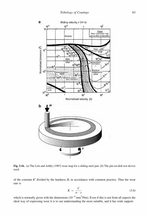
of the constant K0 divided by the hardness H, in accordance with common practice. Thus the wearrate is
K ¼ V
w $ s(3.6)
which is normally given with the dimensions (10�6 mm3/Nm). Even if this is not from all aspects theideal way of expressing wear it is to our understanding the most suitable, and it has wide support.
Fig. 3.16. (a) The Lim and Ashby (1987) wear map for a sliding steel pair. (b) The pin-on-disk test deviceused.
63Tribology of Coatings

There is also a clear physical argument for using the wear rate as defined above because it is theworn volume divided by the mechanical energy input into the contact. The contact energy input can bedescribed as the product of the normal load, the velocity and the applied time which again is the sameas the product of load and distance which we find in the equation. It is strongly recommended that thisway of expressing wear should be taken into use as widely as possible, to make it possible to compareand utilize wear data produced in different contact conditions. The International Research Group onWear of Advanced Materials under the auspices of OECD (IRG OECD) has recently discusseda suggestion to give the unit ‘10�6 mm3/Nm’ a specific name for more convenient data comparison.
In this book the different tribological coatings will be quantitatively compared to each other bycomparing the coefficient of friction and the wear rate. In the literature it is, however, more oftenpossible to find data for the coefficient of friction than for the wear rate. This is unfortunate, because inmany cases it would be more relevant to compare the wear properties than the friction properties.
3.1.5 Lubrication
The most common way of reducing friction and wear is to introduce a lubricant between the twomoving surfaces. If the lubricant manages to prevent contact between the solids, the shearing action,which creates resistance to motion and stresses in the material, will take place either within thelubricant or in the boundary between the lubricant and the solid.
The mechanisms of lubrication can be divided into two main groups, fluid pressure lubrication andsurface film lubrication as shown in Fig. 3.17. These expressions are considered more suitable than
Fig. 3.17. Classification of the mechanisms of lubrication.
64 Coatings Tribology
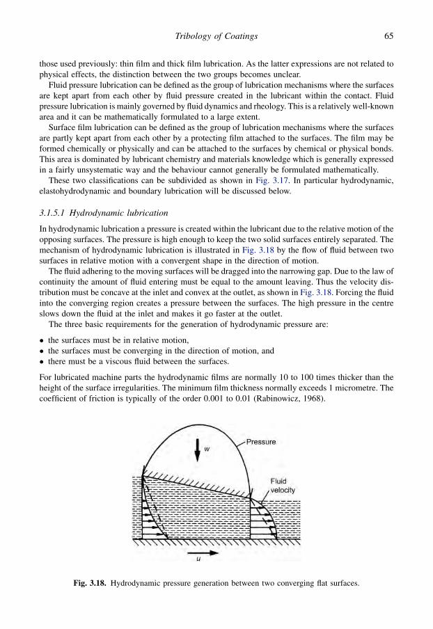
those used previously: thin film and thick film lubrication. As the latter expressions are not related tophysical effects, the distinction between the two groups becomes unclear.
Fluid pressure lubrication can be defined as the group of lubrication mechanisms where the surfacesare kept apart from each other by fluid pressure created in the lubricant within the contact. Fluidpressure lubrication is mainly governed by fluid dynamics and rheology. This is a relatively well-knownarea and it can be mathematically formulated to a large extent.
Surface film lubrication can be defined as the group of lubrication mechanisms where the surfacesare partly kept apart from each other by a protecting film attached to the surfaces. The film may beformed chemically or physically and can be attached to the surfaces by chemical or physical bonds.This area is dominated by lubricant chemistry and materials knowledge which is generally expressedin a fairly unsystematic way and the behaviour cannot generally be formulated mathematically.
These two classifications can be subdivided as shown in Fig. 3.17. In particular hydrodynamic,elastohydrodynamic and boundary lubrication will be discussed below.
3.1.5.1 Hydrodynamic lubrication
In hydrodynamic lubrication a pressure is created within the lubricant due to the relative motion of theopposing surfaces. The pressure is high enough to keep the two solid surfaces entirely separated. Themechanism of hydrodynamic lubrication is illustrated in Fig. 3.18 by the flow of fluid between twosurfaces in relative motion with a convergent shape in the direction of motion.
The fluid adhering to the moving surfaces will be dragged into the narrowing gap. Due to the law ofcontinuity the amount of fluid entering must be equal to the amount leaving. Thus the velocity dis-tribution must be concave at the inlet and convex at the outlet, as shown in Fig. 3.18. Forcing the fluidinto the converging region creates a pressure between the surfaces. The high pressure in the centreslows down the fluid at the inlet and makes it go faster at the outlet.
The three basic requirements for the generation of hydrodynamic pressure are:
� the surfaces must be in relative motion,� the surfaces must be converging in the direction of motion, and� there must be a viscous fluid between the surfaces.
For lubricated machine parts the hydrodynamic films are normally 10 to 100 times thicker than theheight of the surface irregularities. The minimum film thickness normally exceeds 1 micrometre. Thecoefficient of friction is typically of the order 0.001 to 0.01 (Rabinowicz, 1968).
Fig. 3.18. Hydrodynamic pressure generation between two converging flat surfaces.
65Tribology of Coatings

The hydrodynamic pressure is low compared to the strength properties of the solids and will notcause appreciable local deformation. The condition of hydrodynamic lubrication is governed by thebulk physical properties of the lubricant, mainly by the viscosity, and surface effects are negligible.
The basic equation for hydrodynamics was developed by Reynolds (1886). A detailed treatment ofhydrodynamic lubrication is found in numerous books on this subject, e.g. Cameron (1966), Lang andSteinhilpher (1978), Szeri (2001) and Stachowiak and Batchelor (2005).
3.1.5.2 Elastohydrodynamic lubrication
In elastohydrodynamic lubrication (EHD or EHL) the local elastic deformation of the solids providesa coherent hydrodynamic film, which prevents asperity interaction. In non-conformal contacts ofmetal surfaces the changes in the rheological properties of the lubricant, typically a mineral oil, areessential for the formation of an elastohydrodynamic film.
When a viscous lubricant is introduced into the contact between two rotating metal discs, a hy-drodynamic pressure will be generated in the inlet region as shown in Fig. 3.19. This pressure tries toforce the surfaces apart at the same time as the lubricant is dragged into the contact. The deformedcontact region is called the Hertzian region because here the pressure distribution is very close to theHertzian pressure distribution, except for the pressure peak at the rear of the contact.
Even if the maximum pressure in steel contacts is as high as 2 to 3 GPa, it does not squeeze out theoil film for the following reasons:
� a typical elastohydrodynamic film is extremely thin (h¼ 0.05 to 2 mm) and the length and width ofthe contact region is often more than 1000 times greater,� the viscosity of oils increases almost exponentially with pressure so that the lubricant in the centre
of the contact region has a very thick, solid-like consistency, and� the lubricant passes very quickly through the contact region, typically in the order of milliseconds.
Fig. 3.19. Pressure distribution and lubricant film shape in the elastohydrodynamically lubricated contactof two rotating discs.
66 Coatings Tribology
There will be no time for the high Hertzian pressure to squeeze out this poorly flowing thick fluid fromthe long and extremely narrow gap. The coefficient of friction is typically of the order of 0.01 to 0.1.
The first satisfactory analysis in which the effect of elastic deformation and the influence ofpressure on viscosity were taken into account was worked out by Erthel and published by Grubin(1949). More complete numerical solutions were developed by Dowson and Higginson (1966) for linecontacts and Hamrock and Dowson (1981) for elliptical contacts.
The most important practical result of elastohydrodynamic lubrication theory is the formula for thecalculation of the minimum film thickness in the contact. For line contacts the minimum filmthickness formula can be written as suggested by Dowson and Higginson (1961) and later corrected byDowson (1968) in the following form:
H0min ¼ 2:65 $ G0:54 $ U0:70 $ W0:13 (3.7)
where
H0min ¼ hmin =R0 (3.8)
G ¼ a $ E0 (3.9)
U ¼ h0 $ u0
E0 $ R0(3.10)
W ¼ w
E0 $ R0 $ l(3.11)
u0 ¼ 0:5ðu1 þ u2Þ (3.12)
1
E0¼ 1
2$
1 � v2
1
E1þ 1 � v2
1
E2
!(3.13)
1
R0¼ 1
R1þ 1
R2(3.14)
and hmin is the minimum film thickness, a is the pressure exponent of viscosity, h0 is the lubricantviscosity at ambient pressure, w is the total load, l is the axial length of the contact, u1 and u2 are thevelocities of the surfaces, R1 and R2 are the radii of the curvatures of the surfaces, n1 and n2 are thePoisson’s ratios and E1 and E2 the Young’s moduli of elasticity for the solid materials in contact.
The absolute value of the thickness of the film is not a good measure of the effectiveness of lu-brication when very thin films, such as elastohydrodynamic ones, are considered. A better picture isobtained by considering the film thickness in relation to the surface roughness, which is often of thesame order of magnitude. This relationship is called the specific film thickness, l, and it is defined as
l ¼ hmin
R0a(3.15)
where
R0a ¼ffiffiffiffiffiffiffiffiffiffiffiffiffiffiffiffiffiffiffiffiR2
a1 þ R2a2
q(3.16)
and Ra1 and Ra2 are the centreline average values for the roughness of the two surfaces. Typical valuesfor the lubricant film properties are shown in Table 3.2 and a comparison of lubrication regimes atdifferent contact severities is shown in Fig. 3.20.
67Tribology of Coatings

It is a very complex task to explain the frictional behaviour in elastohydrodynamically lubricatedcontacts because Newtonian fluid analysis is not appropriate for predicting the observed tractionbehaviour. A more accurate model incorporating the three classical forms of material shear behaviour,Newtonian viscous, Hookean elastic and plastic yield, was developed by Bair and Winer (1979). Thethree primary physical properties required to use the model are low shear stress viscosity, the limitingelastic shear modulus and the limiting yield shear stress. The last one determines the maximumtraction that can be transmitted in an elastohydrodynamic contact.
Table 3.2. Typical lubricant film properties.
Mechanisms of lubrication Lubricant film properties
Lubricant filmthickness
Specific filmthickness
Coefficientof friction
hmin l m
mm – –
Boundary lubrication 0.005–0.1 <1 0.03–0.2Mixed lubrication 0.01–1 1–4 0.02–0.15Elastohydrodynamic lubrication 0.01–10 3–10 0.01–0.1Hydrodynamic lubrication 1–100 10–100 0.001–0.01
Fig. 3.20. Comparison of contact severities and dominating contact interactions in the different contactregimes (after Hsu and Gates, 2001).
68 Coatings Tribology

The concept of micro-elastohydrodynamic lubrication consists of the theory that the approachbetween two individual asperities will be delayed by a local microscopic elastohydrodynamic action.This action will contribute to the load-carrying capacity and the separation of the surfaces (Cheng,1978).
Reviews of the state of the art in the field of elastohydrodynamic lubrication have been publishedby Cheng (1980), Holmberg (1980, 1982), Spikes (1999), Szeri (2001), Larsson and Hoglund (2004)and Stachowiak and Batchelor (2005).
3.1.5.3 Boundary lubrication
In boundary lubrication the solid surfaces move so close to each other that there is considerableasperity interaction. A very thin lubricant film adsorbs to the solid surfaces and significantly inhibitsasperity welding, as shown in Fig. 3.17. The coefficient of friction is reduced because the lubricantfilm has lower shear strength than the welded asperity junctions and the wear is reduced because ofa smaller number of welded asperity contacts.
Surface interaction phenomena between thin layers of boundary lubricants and the solids dominatethe condition of contact. Thus the tribological characteristics are determined primarily by the physicaland chemical properties of the lubricant and the solids. The rheological properties of the bulklubricant, such as viscosity, play little or no part in the friction and wear behaviour. In boundarylubrication the coefficient of friction is typically of the order 0.03 to 0.2 (Godfrey, 1968).
The following fundamental mechanisms of interaction between the lubricant and the solid areinvolved to produce a protective lubricant film:
� physical adsorption (physisorption),� chemical adsorption (chemisorption), and� chemical reaction.
Physical adsorption occurs when the molecules of the lubricant are held to the surface only by bondssuch as van der Waal’s forces as shown in Fig. 3.21a. No exchange of electrons takes place betweenthe molecules of the adsorbate and the adsorbent. The molecules are weakly bound, the boundarylubricant film has a mono- or multilayer structure and its formation process is reversible. Polarmolecules, i.e. molecules that have a changing electrical charge along their length, such as long chainalcohols, aldehydes or acids, adsorb on to the surface with vertical orientation. The films can be ofeither monomolecular (typically <3 nm) or polymolecular thickness. Many molecules pack in asclosely as possible and strengthen the film with lateral cohesive forces. The film is temperaturesensitive and provides lubrication only at low loads and low sliding velocities.
Chemical adsorption occurs when the lubricant molecules are held to the surface by chemicalbonds as shown in Fig. 3.21b. Electron exchange between the molecules of the adsorbate and theadsorbent takes place. The film might be only a monolayer thick, and the formation is characterized byirreversibility and strong bonding energies. Lubricant films formed by polar molecules of, e.g., fattyacids, soaps and esters lubricate effectively up to their melting point. At temperatures typically in therange of about 120 to 180�C these lubricants fail as a result of reorientation, softening and melting.Films formed by chemical adsorption provide good lubrication at moderate loads, temperatures andsliding velocities.
Chemical reactions between the lubricant molecules and the solid surface occur when there is anexchange of valence electrons and a new chemical compound is formed as shown in Fig. 3.21c. Thelubricating films are unlimited in thickness and characterized by high activation, high bonding en-ergies and irreversibility. The chemically reactive boundary lubricants usually contain sulphur,chlorine or phosphorus atoms in the molecule. They may additionally even contain oxygen, lead, zinc,boron, selenium, etc. (Fein, 1970). The films behave more like solids than viscous liquids but theirshear strength is considerably lower than that of the substrates (Cavdar and Ludema, 1991). The films
69Tribology of Coatings
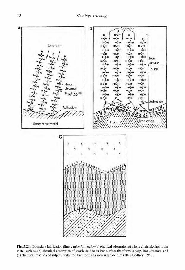
Fig. 3.21. Boundary lubrication films can be formed by (a) physical adsorption of a long chain alcohol to themetal surface, (b) chemical adsorption of stearic acid to an iron surface that forms a soap, iron strearate, and(c) chemical reaction of sulphur with iron that forms an iron sulphide film (after Godfrey, 1968).
70 Coatings Tribology

are more stable than physically and chemically adsorbed films. The chemical reaction and the filmformation is strongly activated at temperatures above 150 to 180�C. The maximum temperature limitfor the reactions varies in the range 300 to 800�C. The lubricant films formed by chemical reactionprovide good lubrication for high loads, high temperatures and high sliding speeds but are limited toreactive materials. These conditions are often referred to as extreme pressure (EP) conditions(Bowden and Tabor, 1950; Fein, 1970; Godfrey, 1968; Cameron, 1980; Bhushan, 1999b; Kajdas,2001; Gellman and Spenser, 2002, 2005; Hsu and Gates, 2001, 2005; Hsu, 2004a, b; Vizintin, 2004;Neville and Morina, 2005; Furlong et al., 2007).
Lubricants are often classified based on the behaviour of their additives: non-reactive, low friction(lubricity), anti-wear and extreme pressure. Non-reactive lubricants are mineral oils without additivesand esters. Low-friction or high-lubricity lubricants are defined as lubricants that have the ability toreduce friction below that of the base oil. The additives are adsorbed on, or they react with, the metalsurface or its oxide layer and form monolayers with low shear strength. Anti-wear additives react withthe surface and form a relatively thick surface film that is not easily removed by load or shear. Theyform organic, metallo-organic or metal salt films on the surface. Zinc dialkyldithiophosphate (ZDDP)and tricresyl phosphate (TCP) are the most widely used anti-wear additives. Extreme pressure ad-ditives are chemically corrosive additives that have strong affinity to the surface. At high loads theyform thick films of high melting point metal salts on the surface which prevent metal to metal contact.By frictional heating they may be removed but new additive molecules rapidly react and build newprotective films. Sulphurized olephines, ZDDP and TCP are common EP additives (Bhushan, 1999b;Hsu and Gates, 2001; Gellman and Spenser, 2005; Morina and Neville, 2007).
The tribological mechanisms of some lubricant additives, such as ZDDP, molybdenumdialkyldhitiocarbamate (MoDTC) and polymers, have recently been the subject of detailed studies.ZDDP forms pad-like structures on the rubbed surfaces. The film formation takes place duringrubbing even at room temperature. The morphology of the reaction film formed depends strongly onthe nature of sliding. Primary and secondary forms of the additive form films of different morphologyand properties. The ZDDP film formation has been found to be proportional to the product of slidingdistance and rubbing time (Fujita and Spikes, 2004; Topolovec and Spikes, 2005). As the severity ofthe loading increases, the resistive forces within the film also increase as the sheared region penetratesdown to the deeper layers of the film (Bec et al., 1999). Canter (2005) showed that in rubbing theZDDP film the zinc changes coordination at a pressure of 17 GPa to form a hexacoordinate, highlycrosslinked structure resulting finally in a fully crosslinked network. The films are formed due to anincrease in pressure.
The MoDTC friction modifier additive forms tiny domains of low friction on the high spots ofrubbed surfaces. Raman analysis indicates that these domains represent crystallites of MoS2. Func-tionalized viscosity modifier polymer additives can form viscous boundary films on rubbed surfaceswhich produce much lower friction than corresponding non-functionalized polymers. It has beenshown that dispersant olefin co-polymer films adsorb to surfaces to form viscous films and that theseresult in reduced friction in thin film conditions (Topolovec and Spikes, 2005).
In boundary lubrication the solid surface should have a high surface energy and high chemicalreactivity, so that there will be a strong tendency for additive molecules to adsorb on the surface andreact with it. Thus, metals tend to be the easiest surfaces to be lubricated. The solid surface should alsohave high wetting property so that the liquid lubricant wets the surface easily (Bhushan, 1999b).A surface coating may radically change the surface properties and also the boundary lubricationmechanisms (Kalin and Vizintin, 2006a; Barros Bouchet et al., 2005; Kano et al., 2005; BarrosBouchet and Martin, 2008). These aspects are discussed in detail in sections 3.4.7 and 6.4.8.
In practice boundary lubrication is a complex phenomenon where the above-mentioned mecha-nisms of surface interaction are mixed with effects of metallurgy, surface roughness, corrosion,catalysis, temperature, pressure and time of reaction. Other environmental components such asoxygen, water and competing surfactants affect the film formation. The load-carrying capacity and the
71Tribology of Coatings

breakthrough conditions for a boundary lubricated coated surface were analysed by Komvopoulos(1991a) and he showed that the elastic or plastic deformation of the surface depends on coatingthickness, surface roughness, microstructure of the coating, normal and friction forces and themechanical properties of the coating and the substrate.
The work of Akhmatov (1966) offers an early insight into the molecular physics involved inboundary lubrication. More recently, Hsu (2004a, b) has reviewed the molecular basis for boundarylubrication. Israelachvili (1992) showed on a molecular level that the static and dynamic properties ofordinary liquids, when confined within a very thin film between two surfaces, can be very different fromthose of the bulk liquid. Films thinner than 10 molecular diameters can become very much more vis-cous. Films below 4 molecular diameters in thickness can undergo a phase transition into a liquid-crystalline or solid-like phase. Such surface films can support a limited load and shear stress. Thesemodified properties depend on the geometry of the liquid molecules, and how these molecules can fit inbetween the two atomically corrugated surfaces.
Different molecular configurations in shearing of boundary molecular thin films are possible, as shownby Fig. 3.22 (Israelachvili, 1992). With no external load, the two surfaces are at rest and stuck to each otherthrough the film (Fig. 3.22a). When a progressively increasing lateral shear stress is applied (Fig. 3.22b)there is a small increase in the lateral displacement and thickness but only by a small fraction of the latticespacing or molecular dimension. The film retains its solid-like ‘frozen’ state and all the strains are elasticand reversible and the surfaces are still stuck to each other. When the applied shear stress has reacheda certain critical value the film suddenly melts (known as shear melting) and the two surfaces begin to sliprapidly over each other (Figs 3.22c, c0 and c00). Depending on the system, a number of different molecular
Fig. 3.22. Schematic illustration of molecular arrangements occurring in a molecularly thin film ofspherical or simple chain molecules between two solid surfaces in shear. (a) The surfaces are at rest,(b) a small shear stress is applied but the surfaces are still stuck to each other, (c, c0 and c00) slipping occurswith three different molecular configurations within the film and (d) refreezing, with the surfaces againstuck to each other (after Israelachvili, 1992).
72 Coatings Tribology
configurations within the film are possible during slipping, shown as (c) total disorder, (c0) partial disorderand (c00) full order. The slip-plane may occur either within the film or at the film–surface interface. Theconfiguration of branched-chained molecules is much less ordered and remains amorphous duringsliding, leading to smoother sliding with reduced friction and little or no stick-slip. The slipping ends oncethe applied shear falls below a critical value, when the film freezes and the surfaces become stuck onceagain (Fig. 3.22d). If the slip mechanism is slow the surfaces will continue to slide smoothly and there willbe no stick-slip. However, unless the liquid molecules are highly entangled or irregular in shape, there willalways be a single stick-slip spike on starting.
The traditional concept of boundary lubrication where adhesion plays a dominating role was criti-cized by Komvopoulos et al. (1986b). They claim that adhesion has only a minor effect and thatploughing due to wear particles entrapped at the interface is the predominant factor in controllingfriction and wear. For evidence they refer to wear grooves formed in surfaces in pin-on-disk experimentswith aluminium, copper and chromium and a relatively inert additive-free mineral oil. It should,however, be noted that their measured coefficients of friction of 0.15 to 0.2 represent very high valuesfor boundary lubrication and that the lubricant and material choice is not good for the formation ofstronger boundary lubrication surface films. This indicates that only a poor boundary lubrication filmwas formed in their experiments. In those conditions, very probably the wear debris ploughingmechanism is dominating, but there are strong indications that this is not the situation in sliding con-ditions when a good boundary lubrication film has been formed resulting in low friction and wear.
The nanomechanical properties of an anti-wear tribofilm produced from phosphorus-containingadditives on boundary-lubricated steel surfaces was measured by Komvopoulos et al. (2004). Theyused a Berkovich diamond tip with 100 nm curvature diameter and normal load between 100 and600 mN to perform indentations on and off a wear track. They found that the phosphate tribofilmexhibited an average hardness of 6.0 GPa and reduced elastic modulus of 122.7 GPa compared to12.5 GPa and 217.6 GPa of the steel substrate, respectively. In nanoscratch test friction measurementswith a 20 mm diamond tip the coefficient of friction of the phosphate tribofilm was 0.23–0.29 while itwas 0.16–0.17 for the steel surface. They attribute the higher friction obtained for the phosphatetribofilm to the contaminant effects of the relatively high surface roughness of the wear track and thegreater plastic flow of the tribofilm compared to the steel substrate. The tribofilm surface containeda large number of ploughing grooves produced by the sliding process, whereas the steel surface onlyhad a small number of surface ridges from polishing.
To support the concept of adhesion dominating the tribology in boundary lubrication, Landheer and deGee (1991) correctly point out that a boundary lubricant film only a few molecules thick, i.e. in thenanometre range, can effectively reduce friction even from 1.0 to 0.1, without affecting asperity in-teraction and the ploughing effect. So the friction-reducing effect must be due to a reduction in the in-terfacial shear strength. The change in shear strength will naturally also affect how the ploughingphenomenon develops, but that is a secondary effect. However, it is obvious that especially in more severeboundary lubricated conditions with higher friction and wear the effect of wear debris ploughing shouldbe taken into account to a larger extent than is generally done. A number of different equations repre-senting special cases of boundary lubrication have been published. Even though there are no seriousinconsistencies in the models, each of them is so limited in its coverage that considerable gaps exist.
It can be deduced from the above that the term ‘boundary lubrication’ is not always well defined. Inthe literature it is often ill understood and overused. However, the recent more systematic studies ona nano- and microlevel are a good starting point for a more holistic understanding of the tribologicalmechanisms involved in the complex contacts of boundary lubrication. The complexity of boundarylubrication is illustrated by the seven characteristic features that Ludema (2005) suggests for moredetailed investigations:
1. Boundary lubrication films are present as patches or islands, ‘washed’ to the front slopes of as-perity clusters. They are neither continuous nor stable.
73Tribology of Coatings
2. There is a gradation of composition and also of properties through the thickness of the film.3. The composition and properties vary with applied load, time of operation, stationary time and
changes of atmosphere.4. New surfaces, though unprotected by a boundary film, survive for a time though they are incapable
of carrying an overload. After some time of sliding the boundary film forms, which prepares thesurface for overload, and even then some time at overload is required to cause failure.
5. Surface material makes a difference: boundary lubricated grey cast iron will carry twice the loadbefore scuffing failure than will tempered martensite of the same hardness.
6. The shape of sliding contact regions and pathway of sliding are important, probably relating to theavailability of protecting chemical elements or compounds.
7. The usual failure criteria for lubricated sliding are not applicable, such as the lambda ratio, theplasticity indices or the maximum surface temperature limit criterion.
3.1.5.4 Mixed lubrication
Mixed lubrication is often referred to as a separate lubrication regime. In this regime the contactbehaviour is governed by a mixture of elastohydrodynamic (or hydrodynamic) lubrication andboundary lubrication. The surfaces are largely separated by a thin lubricant film but asperity contactstill takes place. The total applied load is thought to be partly carried by asperity contacts and partly byhydrodynamic action.
Mixed lubrication has been defined for conditions where the specific film thickness, l, is in therange of about 1 to 4. In a comprehensive study of mixed lubrication phenomena Tallian (1972) foundthat boundary lubrication effects dominate the load-carrying mechanism when l< 1.5, while elas-tohydrodynamic effects dominate when l> 1.5. According to this theoretical treatment the entireload is carried by asperity interactions when l< 0.4, which was considered a minimum value for thespecific film thickness. More recent experience indicates that the elastohydrodynamic lubricationmechanism may play an active role and separate the moving surfaces in some cases even at values aslow as 0.1 and below. Theoretical approaches to the contact behaviour in mixed lubrication have beenpresented by Tallian et al. (1966), Tallian (1972), Christensen (1971, 1972), Johnson et al. (1972),Patir and Cheng (1978), Andersson et al. (2004) and Geike and Popov (2008).
Our knowledge of mixed lubrication is still poor and the theories suggested need experimentalconfirmation. This will not be an easy task for the future. When concentrated contacts are considered,some authors prefer to use the term partial elastohydrodynamic lubrication instead of mixedlubrication.
3.1.5.5 Lubrication with solid lubricants
In solid lubrication the lubricating material is not a liquid but a solid material, often in powder or flakeform. The solid material acts in the same way as a liquid lubricant. It inhibits direct contact betweenthe two sliding surfaces and allows the shear to take place within the solid lubricant. For that reasonmaterials with a lamellar structure are especially suitable as solid lubricants, such as molybdenumdisulphide, graphite, hexagonal boron nitride and boric acid. Other materials that are used as solidlubricants are polytetrafluoroethylene (PTFE), polyimide, soft metals, some oxides and rare-earthfluorides, diamond, diamond-like amorphous carbon and fullerenes. The coefficient of friction insliding contacts with solid lubricants is typically in the range of m¼ 0.05–0.25 (Savan et al., 2000;Lansdown, 1999; Erdemir, 2001a; Stachowiak and Batchelor, 2005).
Solid lubricants are often used in very severe conditions where liquid lubrication has limitations.Such conditions are vacuum, very high and very low temperatures, extremely high contact pressure,radiation, etc. However, the limitations of solid lubrication are typically low capability to conduct heat
74 Coatings Tribology

transfer from the contact, limited wear life because the material replenishment is more difficultcompared to liquid lubrication, unstable frictional behaviour and chemical changes which affect theirtribological behaviour.
Solid lubricants may also be dispersed in water, oil or grease resulting in a combined effect of solidand liquid lubrication. There has been a growing interest in the use of fullerenes as solid additives inliquid lubrication (Rapoport et al., 2005). The mechanisms related to solid lubrication by differentcoating materials such as graphite, polytetrafluoroethylene, molybdenum disulphide and diamond-likecarbon surface films are discussed in Chapter 4.
3.2 Surface Stresses and Response to Loading
3.2.1 Response of materials to loading
In tribological contacts there are at least two surfaces in relative motion interacting with each other.The phenomena that take place in the contact are considerably influenced by the force pressing thetwo surfaces together. The normal force and the shape of the surfaces determine the contact pressurethat produces a load on both surfaces. The frictional force that resists motion is an additionaltangential load on the area of contact.
A distinction between conforming and non-conforming contacts is made based on the shapes of thesurfaces. A contact is said to be conforming if the surfaces fit close together without appreciabledeformation as in Fig. 3.23a. Non-conforming contacts have dissimilar surface profiles, as illustratedin Fig. 3.23b. When non-conforming contacts are brought together they will first touch at a point oralong a line. According to this they are called point contacts or line contacts. For conforming contactsthe contact area is large and the contact pressure is low while for non-conforming contacts the contactarea is small and the contact pressure high.
The contact pressure will create stresses and deformation in the material close to the contact. Weknow that different materials respond differently when loaded. Based on their behaviour we distin-guish between elastic, plastic and viscous materials. Materials which combine these characteristicsare common, for example steel exhibits elastoplastic properties and polymers are generallyviscoelastic.
Fig. 3.23. (a) The conforming contact between a shaft and bushing and (b) the non-conforming contactbetween two cylinders.
75Tribology of Coatings

Elastic materials are characterized by a reversible deformation when loaded. They first deform butwhen the load is removed they nearly instantaneously return to their original shape, as shown inFig. 3.24a. In deformation the atoms are not permanently displaced. The work done by external load isstored in the body as distortion of the interatomic bonds. The relation between stress and strain belowthe yield point is essentially linear.
Plastically deforming materials represent a more complex stress–strain relationship and the de-formation persists even after removal of the load. When the load-induced stresses increase abovea yield point the material can no longer accommodate the high stresses and it retains time-independent deformation and will no longer return to its original shape, Fig. 3.24b. The bondsbetween initially neighbouring atoms are broken and a new set of bonds is established which are asstable as the original ones. On release of load the new configuration is maintained and the de-formation is permanent.
Viscous materials have the capacity to dissipate mechanical energy but not store it. In viscousdeformation the viscous force, which tends to slow down the faster moving surface, is proportional tothe velocity gradient between the surfaces. The viscous deformation is time dependent. Detailedtreatments of the different forms of material response to external loading are found in textbooks suchas Timoshenko and Goodier (1970), Johnson and Mellor (1983), Jacobsson (1991), Ashby (1999) andBhushan (1999b).
When the stress level in the material exceeds a material-dependent critical value fracture takesplace. Fracture is the separation of a body into two or more pieces in response to an imposed stress,Fig. 3.24c. The fracture can be caused by tensile stress or shear stress. Materials are categorized asductile or brittle depending on their fracture behaviour. The fracture processes involves first crackinitiation and then crack propagation. Ductile fracture is characterized by a large amount of plasticdeformation in the vicinity of an advancing crack. In brittle fracture cracks are spread extremelyrapidly, with very little accompanying plastic deformation, typically less than 5%, and result ina sudden separation of a stressed body into two or more parts.
Propagation of the crack to a larger area of fracture results in material liberation and the creation ofwear particles. The process from loading to material removal is shown schematically in Fig. 3.25.
Fig. 3.24. Three characteristic ways for a material to respond to external load: (a) elastic deformation,(b) plastic deformation and (c) material fracture.
76 Coatings Tribology
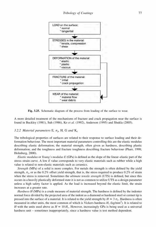
A more detailed treatment of the mechanisms of fracture and crack propagation near the surface isfound in Buckley (1981), Suh (1986), Ko et al. (1992), Anderson (1995) and Shukla (2005).
3.2.2 Material parameters E, sy, H, G and Kc
The tribological properties of surfaces are related to their response to surface loading and their de-formation behaviour. The most important material parameters controlling this are the elastic modulusdescribing elastic deformation; the material strength, often given as hardness, describing plasticdeformation; and the toughness and fracture toughness describing fracture behaviour (Pharr, 1998;Holmberg, 2000).
Elastic modulus or Young’s modulus E (GPa) is defined as the slope of the linear–elastic part of thestress–strain curve. A low E value corresponds to very elastic materials such as rubber while a highvalue is related to non-elastic materials such as ceramics.
Strength (MPa) of a solid is more complex. For metals the strength is often defined by the yieldstrength, sy, or as the 0.2% offset yield strength, that is, the stress required to produce 0.2% of strainwhen the stress is removed. Sometimes the ultimate tensile strength (UTS) is defined, but since thisoccurs in a heavily plastically deformed state it is not as common to utilize UTS as a design parameterunless a high safety factor is applied. As the load is increased beyond the elastic limit, the strainincreases at a greater rate.
Hardness H (MPa) is a crude measure of material strength. The hardness is defined by the indenternormal force divided by the projected area of the indent as a diamond or hardened steel or cermet tip ispressed into the surface of a material. It is related to the yield strength by H z 3 sy. Hardness is oftenmeasured in other units, the most common of which is Vickers hardness Hv (kg/mm2). It is related toH with the units used above as H z 10 Hv. However, increasingly GPa is being used as a universalhardness unit – sometimes inappropriately, since a hardness value is test method dependent.
Fig. 3.25. Schematic diagram of the process from loading of the surface to wear.
77Tribology of Coatings
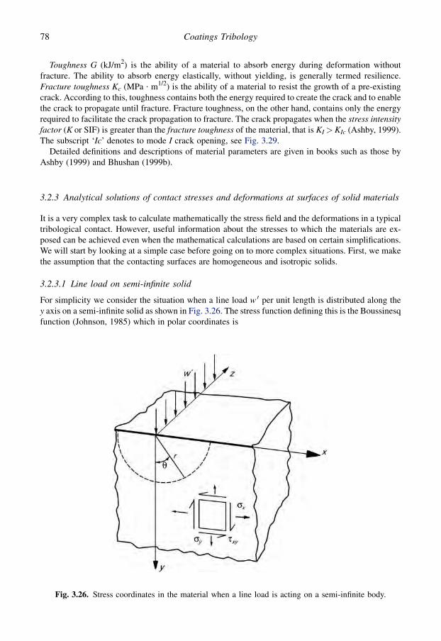
Toughness G (kJ/m2) is the ability of a material to absorb energy during deformation withoutfracture. The ability to absorb energy elastically, without yielding, is generally termed resilience.Fracture toughness Kc (MPa $ m1/2) is the ability of a material to resist the growth of a pre-existingcrack. According to this, toughness contains both the energy required to create the crack and to enablethe crack to propagate until fracture. Fracture toughness, on the other hand, contains only the energyrequired to facilitate the crack propagation to fracture. The crack propagates when the stress intensityfactor (K or SIF) is greater than the fracture toughness of the material, that is KI> KIc (Ashby, 1999).The subscript ‘Ic’ denotes to mode I crack opening, see Fig. 3.29.
Detailed definitions and descriptions of material parameters are given in books such as those byAshby (1999) and Bhushan (1999b).
3.2.3 Analytical solutions of contact stresses and deformations at surfaces of solid materials
It is a very complex task to calculate mathematically the stress field and the deformations in a typicaltribological contact. However, useful information about the stresses to which the materials are ex-posed can be achieved even when the mathematical calculations are based on certain simplifications.We will start by looking at a simple case before going on to more complex situations. First, we makethe assumption that the contacting surfaces are homogeneous and isotropic solids.
3.2.3.1 Line load on semi-infinite solid
For simplicity we consider the situation when a line load w 0 per unit length is distributed along they axis on a semi-infinite solid as shown in Fig. 3.26. The stress function defining this is the Boussinesqfunction (Johnson, 1985) which in polar coordinates is
Fig. 3.26. Stress coordinates in the material when a line load is acting on a semi-infinite body.
78 Coatings Tribology
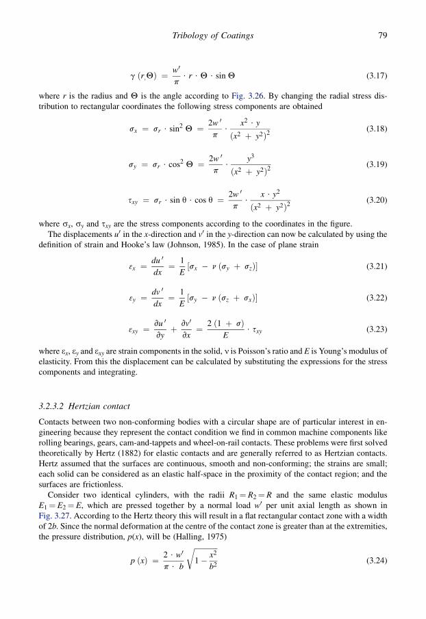
g ðr;QÞ ¼w0
p$ r $ Q $ sin Q (3.17)
where r is the radius and Q is the angle according to Fig. 3.26. By changing the radial stress dis-tribution to rectangular coordinates the following stress components are obtained
sx ¼ sr $ sin2 Q ¼ 2w 0
p$
x2 $ y
ðx2 þ y2Þ2(3.18)
sy ¼ sr $ cos2 Q ¼ 2w 0
p$
y3
ðx2 þ y2Þ2(3.19)
sxy ¼ sr $ sin q $ cos q ¼ 2w 0
p$
x $ y2
ðx2 þ y2Þ2(3.20)
where sx, sy and sxy are the stress components according to the coordinates in the figure.The displacements u0 in the x-direction and v0 in the y-direction can now be calculated by using the
definition of strain and Hooke’s law (Johnson, 1985). In the case of plane strain
3x ¼du 0
dx¼ 1
E½sx � n ðsy þ szÞ� (3.21)
3y ¼dv 0
dx¼ 1
E½sy � n ðsz þ sxÞ� (3.22)
3xy ¼vu 0
vyþ vv0
vx¼ 2 ð1 þ sÞ
E$ sxy (3.23)
where 3x, 3y and 3xy are strain components in the solid, n is Poisson’s ratio and E is Young’s modulus ofelasticity. From this the displacement can be calculated by substituting the expressions for the stresscomponents and integrating.
3.2.3.2 Hertzian contact
Contacts between two non-conforming bodies with a circular shape are of particular interest in en-gineering because they represent the contact condition we find in common machine components likerolling bearings, gears, cam-and-tappets and wheel-on-rail contacts. These problems were first solvedtheoretically by Hertz (1882) for elastic contacts and are generally referred to as Hertzian contacts.Hertz assumed that the surfaces are continuous, smooth and non-conforming; the strains are small;each solid can be considered as an elastic half-space in the proximity of the contact region; and thesurfaces are frictionless.
Consider two identical cylinders, with the radii R1¼ R2¼ R and the same elastic modulusE1¼ E2¼ E, which are pressed together by a normal load w0 per unit axial length as shown inFig. 3.27. According to the Hertz theory this will result in a flat rectangular contact zone with a widthof 2b. Since the normal deformation at the centre of the contact zone is greater than at the extremities,the pressure distribution, p(x), will be (Halling, 1975)
p ðxÞ ¼ 2 $ w0
p $ b
ffiffiffiffiffiffiffiffiffiffiffiffiffi1� x2
b2
r(3.24)
79Tribology of Coatings
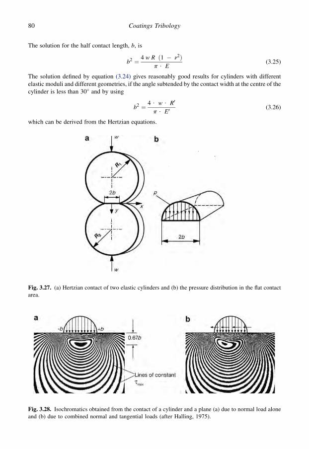
The solution for the half contact length, b, is
b2 ¼ 4 w R ð1 � n2Þp $ E
(3.25)
The solution defined by equation (3.24) gives reasonably good results for cylinders with differentelastic moduli and different geometries, if the angle subtended by the contact width at the centre of thecylinder is less than 30� and by using
b2 ¼ 4 $ w $ R0
p $ E0(3.26)
which can be derived from the Hertzian equations.
Fig. 3.27. (a) Hertzian contact of two elastic cylinders and (b) the pressure distribution in the flat contactarea.
Fig. 3.28. Isochromatics obtained from the contact of a cylinder and a plane (a) due to normal load aloneand (b) due to combined normal and tangential loads (after Halling, 1975).
80 Coatings Tribology

The maximum contact pressure can be derived to be (Bhushan, 1999b)
p0 ¼3$w
2$p$b2¼
ffiffiffiffiffiffiffiffiffiffiffiffiffiffiffiffi6$w$E02
p3$R023
r(3.27)
The stress field created by a spherical sliding contact on a flat surface was derived by Hamilton andGoodman (1966) and Hamilton (1983). Complete mathematical analysis of the stress distribution ina Hertzian contact is found in Johnson (1985) and Suh (1986).
The patterns of lines of constant maximum shear stress (isochromatics) in a Hertzian contactof a cylinder and a plane due to normal load alone are shown in Fig. 3.28a. The greatest valueof maximum shear stress occurs below the surface at a distance of 0.67b which corresponds to aboutone-third of the total contact length.
When the contact is due to combined normal and tangential loads, as shown in Fig. 3.28b, theposition of maximum shear stress moves towards the surface with increasing tangential load. It can beshown (Schouten, 1973a, b) that for coefficients of friction exceeding 0.32 the maximum shear stresswill be found on the surface as shown in Fig. 3.13. This is extremely important when stresses ina coated surface are considered because it determines whether the maximum shear stress will occur inthe coating, in the substrate or at the interface.
3.2.4 Criteria for plastic yield
The limit for the elastic deformation can be described as a criterion for plastic yield. The conditions atwhich the stresses in the material are higher than that which the material can take elastically define thebeginning of plastic flow or plastic yield. This is related to the yield point of the material in simpletension or pure shear through an appropriate yield criterion. Two commonly used criteria are Tresca’smaximum shear stress criterion and von Mises shear strain energy criterion.
In Tresca’s maximum shear stress criterion the yielding will occur when the maximum shear stress,which is half of the difference between the maximum and minimum principal stress, reaches the yieldstress in pure shear or half of the yield stress in simple tension. This can be expressed as
smax � smin ¼ 2sy (3.28)
where smax and smin are the maximum and minimum principal stresses, and sy is the yield strength ofthe material in shear.
In the von Mises shear strain energy criterion, yielding will occur when the distortion energyequals the distortion energy at yield in simple tension or pure shear. Shear stresses in the materialresult in dislocation movements and deformations. The deformations are, however, not influenced bythe hydrostatic stress which only results in changes of volume. The yield criteria can therefore beexpressed in terms of deviator stresses, Gi, instead of actual principal stresses, si, as
Gi ¼ si � sm (3.29)
where sm is the hydrostatic stress.The von Mises maximum shear strain energy relation is a deviatoric stress relation for yield that is
in wide use and has been found to be in good agreement with experiments (Tangena, 1987; Sainsotet al., 1990). The criterion states that yield is dependent on all three values of deviatoric stresses andthat deformation occurs when the distortion energy reaches a critical value. This occurs at a yieldstress, s 0, when
s0 ¼ 1ffiffiffi2p
ffiffiffiffiffiffiffiffiffiffiffiffiffiffiffiffiffiffiffiffiffiffiffiffiffiffiffiffiffiffiffiffiffiffiffiffiffiffiffiffiffiffiffiffiffiffiffiffiffiffiffiffiffiffiffiffiffiffiffiffiffiffiffiffiffiffiffiffiffiffiffiffiffiffiffiffiffiffiffiffiffiffiffiffiffiffiffiffiffiffiffiðG1 � G2Þ2 þ ðG2 � G3Þ2 þ ðG1 � G3Þ2
q(3.30)
81Tribology of Coatings
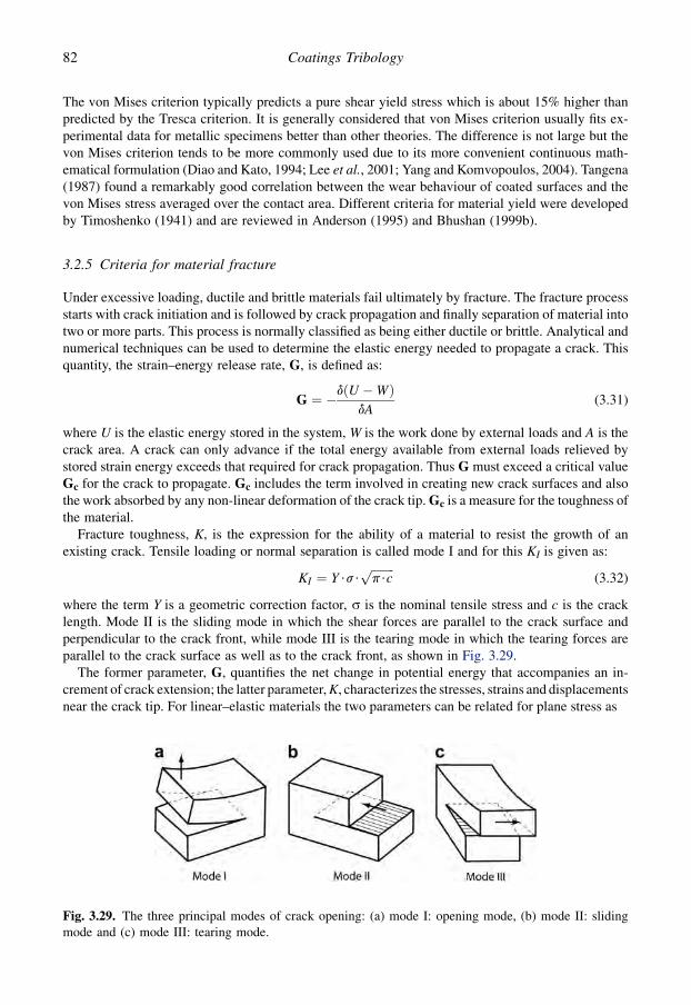
The von Mises criterion typically predicts a pure shear yield stress which is about 15% higher thanpredicted by the Tresca criterion. It is generally considered that von Mises criterion usually fits ex-perimental data for metallic specimens better than other theories. The difference is not large but thevon Mises criterion tends to be more commonly used due to its more convenient continuous math-ematical formulation (Diao and Kato, 1994; Lee et al., 2001; Yang and Komvopoulos, 2004). Tangena(1987) found a remarkably good correlation between the wear behaviour of coated surfaces and thevon Mises stress averaged over the contact area. Different criteria for material yield were developedby Timoshenko (1941) and are reviewed in Anderson (1995) and Bhushan (1999b).
3.2.5 Criteria for material fracture
Under excessive loading, ductile and brittle materials fail ultimately by fracture. The fracture processstarts with crack initiation and is followed by crack propagation and finally separation of material intotwo or more parts. This process is normally classified as being either ductile or brittle. Analytical andnumerical techniques can be used to determine the elastic energy needed to propagate a crack. Thisquantity, the strain–energy release rate, G, is defined as:
G ¼ �dðU �WÞdA
(3.31)
where U is the elastic energy stored in the system, W is the work done by external loads and A is thecrack area. A crack can only advance if the total energy available from external loads relieved bystored strain energy exceeds that required for crack propagation. Thus G must exceed a critical valueGc for the crack to propagate. Gc includes the term involved in creating new crack surfaces and alsothe work absorbed by any non-linear deformation of the crack tip. Gc is a measure for the toughness ofthe material.
Fracture toughness, K, is the expression for the ability of a material to resist the growth of anexisting crack. Tensile loading or normal separation is called mode I and for this KI is given as:
KI ¼ Y$s$ffiffiffiffiffiffiffiffip$cp
(3.32)
where the term Y is a geometric correction factor, s is the nominal tensile stress and c is the cracklength. Mode II is the sliding mode in which the shear forces are parallel to the crack surface andperpendicular to the crack front, while mode III is the tearing mode in which the tearing forces areparallel to the crack surface as well as to the crack front, as shown in Fig. 3.29.
The former parameter, G, quantifies the net change in potential energy that accompanies an in-crement of crack extension; the latter parameter, K, characterizes the stresses, strains and displacementsnear the crack tip. For linear–elastic materials the two parameters can be related for plane stress as
Fig. 3.29. The three principal modes of crack opening: (a) mode I: opening mode, (b) mode II: slidingmode and (c) mode III: tearing mode.
82 Coatings Tribology

G ¼ K2I =E (3.33)
For plane strain conditions E must be replaced by E/(1� n2) where E is Young’s modulus and n isPoisson’s ratio (Thouless, 1988; Anderson, 1995; Bhushan, 1999b).
3.2.6 Analytical solutions of stresses and deformations in normally loaded coated surfaces
The correct determination of stresses and deformations in surfaces in tribological contacts is im-portant as it forms the basis for the surface mechanisms resulting in friction and wear. In thefollowing paragraphs we will discuss early analytical and numerical solutions for coated surfaces inloaded contacts. Today, a more powerful tool for solving stresses and deformations in solids is thefinite element method (FEM) for modelling and simulation, which we will discuss in detail insection 3.2.8.
We will first consider the stress field and deformations generated in a layered surface when it isloaded normally by an indenter. We assume that the material is homogeneous, the surfaces are smoothand no residual stresses are present. This will be followed by separate considerations of how the stressfield and the deformations are influenced by tangential movement of the indenter, surface roughness,cracks and flaws near the surface and residual stresses such as thermal and intrinsic stresses(Fig. 3.30).
A number of analytical solutions have been developed for the contact situation when one smoothnon-conformal surface is pressed against a layered counterface without sliding. The layers are con-sidered elastic and the substrates either elastic or rigid. In some of the solutions the friction betweenthe contacting surfaces is taken into account. Most solutions are for the contact of a ball or a cylinderagainst a coated plane substrate. The analytical solutions give the possibility to study effects of pa-rameters such as coating thickness, geometry, load, shear strength, Young’s modulus and Poisson’sratio on the contact stresses, contact area, deformations, subsurface stresses and subsurface strains.A summary of published analytical treatments is presented in Table 3.3.
Most of the analytical solutions are based on the classical elasticity theory starting from theBoussinesq stress function. This makes the mathematical treatment fairly complex. Because the
Fig. 3.30. The stress field and deformations in the ideal case of a slider moving tangentially on a coatedsurface is disturbed in practical situations by (a) surface roughness, (b) cracks and flaws, and (c) residualinternal stresses such as thermal and intrinsic stresses.
83Tribology of Coatings

Table 3.3. Analytical solutions for the contact problem with layered surfaces.
Reference Elasticcoating
Elasticsubstrate
Rigidsubstrate
Elasticcounterface
Rigidcounterface
Ball onplane
Cylinder onplane
Cone onplane
Cylinder oncylinder
Multilayers
IndentationMeijers (1968) X X X XChen and Engel (1972) X X X X X XGupta et al. (1973) X X X XGupta and Walowit (1974) X X X X X XEl-Sherbiney and Halling (1976) X X X XMatthewson (1981) X X X X XChiu and Harnett (1983) X X X XSolecki and Ohgushi (1984) X X X X X XRamsey et al. (1991) X X X XDjabella and Arnell (1992) X X X X XBragallini et al. (2003) X X X XSlidingChang et al. (1983) X X X XKing and O’Sullivan (1987) X X X XO’Sullivan and King (1988) X X X XAhn and Roylance (1990) X X X X
84
Co
atin
gs
Trib
olo
gy

Reference Contactpressure
Contactdeformation
Contactarea
Subsurfacestresses
Subsurfacestrain
Threedimensional
Analytical Numericalcomputations
Experimental
IndentationMeijers (1968) X X X XChen and Engel (1972) X X X X XGupta et al. (1973) X X XGupta and Walowit (1974) X X XEl-Sherbiney and Halling (1976) X X XMatthewson (1981) X X X X X XChiu and Harnett (1983) X X X X X X XSolecki and Ohgushi (1984) X X X XRamsey et al. (1991) X X X XDjabella and Arnell (1992) X X X XBragallini et al. (2003) X X XSlidingChang et al. (1983) X X X XKing and O’Sullivan (1987) X X XO’Sullivan and King (1988) X X XAhn and Roylance (1990) X X
85
Trib
olo
gy
of
Co
atin
gs
solutions are mathematically quite intensive they will only be commented on briefly below. The fullmathematical treatment is found in the references given.
The agreement between the theoretical models and real contacts is often not easy to estimatebecause most of the reported models do not include experimental comparisons.
A deviation from experimental results will naturally occur as long as the models do not take intoaccount influencing parameters like surface roughness, material inhomogeneity and voids and thechanging material properties in the mixed layer at the interface between the coating and substratesurface.
3.2.6.1 Contact pressure and stresses
The pressure distribution for a rigid cylinder indenting an elastic layer on a rigid substrate has beensolved analytically by Meijers (1968), on an elastic substrate by Chiu and Harnett (1983) and for bothelastic and rigid cylinders with coatings on elastic substrates by Gupta and Walowit (1974). The situationof one or several elastic layers indented by a parabolic counterface has been solved by Chen and Engel(1972). They also performed ball dropping experiments with a steel ball on to a nylon layer on a granitesurface. By measuring the contact times they obtained good correlation with analytical predictions.
The cylinder against cylinder situation with either one or both coated and with either elastic or rigidsubstrates under the elastic coating has been solved by Solecki and Ohgushi (1984). A strain approachhas been proposed by Bragallini et al. (2003) as a more simple method, where the stress analysis iscarried out in terms of strains of the coating/substrate system. This method is used to evaluate the riskof coating failure for both hard and soft coatings, once the elastic modulus of the coating and thesubstrate and the coating thickness are known.
3.2.6.2 Normal approach and contact area
Solutions for the normal approach are given in the above situations by Meijers (1968), Chen and Engel(1972), Gupta and Walowit (1974), Chiu and Harnett (1983) and Solecki and Ohgushi (1984). Cal-culations for both the normal approach and the size of the contact area with an elastic spherical in-denter against an elastic coating on a rigid substrate are presented by El-Sherbiney and Halling(1976). The size of the contact area is solved for a similar situation but with an elastic substrate byChiu and Harnett (1983).
3.2.6.3 Subsurface stresses and strains
An analytical solution including a simplifying approximation enabled Matthewson (1981) to de-termine the stresses and strains within an elastic coating on a rigid substrate, averaged through thethickness of the coating and with particular profiles of rigid indenters. The stress distribution withinthe coating was found to be extremely sensitive to the Poisson’s ratio of the coating. It was also foundthat the interfacial shear stress between the coating and the substrate is largest for almost in-compressible materials, and therefore these materials are more likely to debond than others.The analysis can be used to predict properties and minimum useful thicknesses for coatings requiredin situations like a rubber coating on a hard substrate. Good agreement of the model with experimentalresults from contact radius and indentation measurements with spherical and conical indenters againstsilicone rubber on glass was achieved.
Subsurface stresses have been calculated by Chiu and Harnett (1983) for arbitrary surface shapeswith an elastic layer on an elastic substrate. The numerical calculations show that when Young’smodulus of the substrate is chosen to be one-third of that of the layer, as in steel layers on aluminiumsubstrates, some degree of ‘contact softening’ occurs and is characterized by increased deformationand decreased contact pressure. These kinds of situations are present in transmission systems wherea thin steel bearing is supported by a housing made of softer material such as aluminium or
86 Coatings Tribology
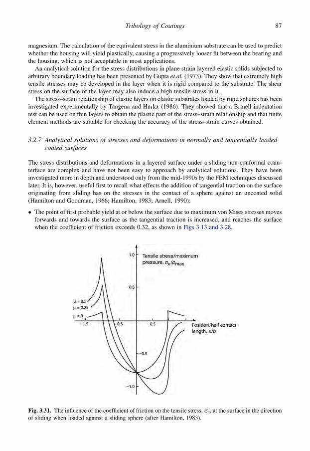
magnesium. The calculation of the equivalent stress in the aluminium substrate can be used to predictwhether the housing will yield plastically, causing a progressively looser fit between the bearing andthe housing, which is not acceptable in most applications.
An analytical solution for the stress distributions in plane strain layered elastic solids subjected toarbitrary boundary loading has been presented by Gupta et al. (1973). They show that extremely hightensile stresses may be developed in the layer when it is rigid compared to the substrate. The shearstress on the surface of the layer may also induce a high tensile stress in it.
The stress–strain relationship of elastic layers on elastic substrates loaded by rigid spheres has beeninvestigated experimentally by Tangena and Hurkx (1986). They showed that a Brinell indentationtest can be used on thin layers to obtain the plastic part of the stress–strain relationship and that finiteelement methods are suitable for checking the accuracy of the stress–strain curves obtained.
3.2.7 Analytical solutions of stresses and deformations in normally and tangentially loadedcoated surfaces
The stress distributions and deformations in a layered surface under a sliding non-conformal coun-terface are complex and have not been easy to approach by analytical solutions. They have beeninvestigated more in depth and understood only from the mid-1990s by the FEM techniques discussedlater. It is, however, useful first to recall what effects the addition of tangential traction on the surfaceoriginating from sliding has on the stresses in the contact of a sphere against an uncoated solid(Hamilton and Goodman, 1966; Hamilton, 1983; Arnell, 1990):
� The point of first probable yield at or below the surface due to maximum von Mises stresses movesforwards and towards the surface as the tangential traction is increased, and reaches the surfacewhen the coefficient of friction exceeds 0.32, as shown in Figs 3.13 and 3.28.
Fig. 3.31. The influence of the coefficient of friction on the tensile stress, sx, at the surface in the directionof sliding when loaded against a sliding sphere (after Hamilton, 1983).
87Tribology of Coatings

88 Coatings Tribology
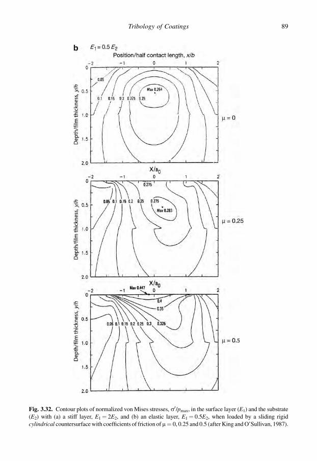
Fig. 3.32. Contour plots of normalized von Mises stresses, s0/pmax, in the surface layer (E1) and the substrate(E2) with (a) a stiff layer, E1¼ 2E2, and (b) an elastic layer, E1¼ 0.5E2, when loaded by a sliding rigidcylindrical countersurface with coefficients of friction of m¼ 0, 0.25 and 0.5 (after King and O’Sullivan, 1987).
89Tribology of Coatings
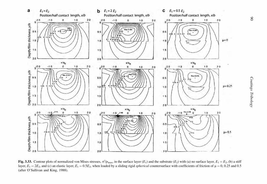
Fig. 3.33. Contour plots of normalized von Mises stresses, s0/pmax, in the surface layer (E1) and the substrate (E2) with (a) no surface layer, E1¼ E2, (b) a stifflayer, E1¼ 2E2, and (c) an elastic layer, E1¼ 0.5E2, when loaded by a sliding rigid spherical countersurface with coefficients of friction of m¼ 0, 0.25 and 0.5(after O’Sullivan and King, 1988).
90
Co
atin
gs
Trib
olo
gy

� A new high-stress region develops at the back edge of the contact, and this is the most likely regionfor yield for friction coefficients greater than 0.25.� The frictional traction adds a compressive stress at the front edge of the contact and intensifies the
tensile stress at the back edge. The intensification of the tensile stress is considerable, as shown inFig. 3.31. Thus the region near the back edge of the contact is the most likely place for failure due toyield in tension.
The situation changes as a thin layer, like a surface coating, is deposited on top of the surface. The slipbetween an elastic layer and a substrate uniformly pressed together, caused by a normal force movingsteadily over the surface, has been analysed and solved numerically by Chang et al. (1983). Theyshow that two asymmetric slip zones are generated if the force exceeds a friction-dependent criticalvalue. The slip is opposite in direction in the two zones, but due to the lack of symmetry, a nettangential shift of the layer is left behind by the passage of the force. This net shift is influenced by thecoefficient of friction. For high coefficients of friction, above 0.5, the layer creeps in the direction ofmotion, while for low coefficients, below 0.25, the creep direction is backwards. The latter result hasbeen observed experimentally.
The contact stress conditions in a layered elastic flat surface at and below the surface were ana-lytically solved with a rigid cylindrical sliding countersurface by King and O’Sullivan (1987) andwith a rigid spherical sliding countersurface by O’Sullivan and King (1988). They relate the stressesto the risk of yield in the coating system, and the calculated von Mises stresses for a stiff layer areshown in Fig. 3.32 and for an elastic layer in Fig. 3.33 at different values of the coefficient of friction.For m¼ 0 the presence of the stiff layer, E1¼ 0.5E2, brings the point of maximum von Mises stressclose to the interface, and the maximum is 40% higher than in the non-layered case. For m¼ 0.25 themaximum stress moves closer to the surface compared with the non-layered case, and its value is alsoapproximately 40% higher than in the non-layered case. For m¼ 0.5 the von Mises stress hasa maximum at the surface for both the layered and the non-layered cases but its value is 52% higher inthe non-layered case. The presence of an elastic layer, E1¼ 0.5E2, results in correspondingly lowervon Mises stresses as shown in Fig. 3.33.
The results show that the value of Young’s modulus of the layer relative to the substrate has a strongeffect on the potential for yielding in both the layer and the substrate as well as on the adhesionstresses at the layer/substrate interface. The maximum tensile stress on the surface depends stronglyon both the friction coefficient and the value of E1 relative to E2. In general, for a fixed value of thesubstrate Young’s modulus, the stresses increase for higher values of the layer’s Young’s modulus.The strong influence of the coefficient of friction reported is partly due to the high values, m¼ 0.25and 0.5, used in the calculations. Corresponding subsurface stress distributions for the contact witha rigid sphere sliding against uncoated and coated surfaces are shown in Fig. 3.33.
A thermomechanical wear transition model for coated surfaces was used by Cowan and Winer(1993) to study how sliding surfaces in contact produce a stress field and frictional heat source thatmay induce severe wear from material yielding. Based on isothermal and thermal factors, filmthickness and material combinations are evaluated so as to minimize the probability of thermo-mechanical wear. A procedure for determining the combined thermal and mechanical stresses inconcentrated sliding contacts has been utilized to predict the failure condition of layered solids byAhn and Roylance (1990, 1992) and Ahn (1993).
A displacement formulation method was used by Ramalingam and Zhen (1995) to calculate layer/substrate interface stresses for line and extended distributed surface loadings. The layer/substrateinterface stress calculations show that a hard coating is a viable solution for wear protection in ex-tended contacts even when the substrate Young’s modulus is as low as 0.2 of that of the coatingmodulus.
The stress distribution of a coated surface with a range of film thickness and elastic propertieswas analysed by Fujino et al. (2007) in elastohydrodynamic lubricated conditions. They used
91Tribology of Coatings

a three-dimensional analysis of the maximum shear stress applied into the coated film and substrateand concluded that an optimal surface design solution is one where the coated film has a largethickness and a smaller modulus of elasticity than that of the substrate is preferable.
3.2.8 Finite element method modelling and simulation of stresses and deformations
The analytical solutions of the stresses and deformations give important information about the generalbehaviour of a sliding contact. Still, due to the complexity of a real tribological contact and due to thegreat number of contact parameters influencing both the friction and wear process, the analyticalsolutions describe a contact idealized with regard to, e.g., geometry, surface roughness, materialhomogeneity, etc. The rapid development in finite element method (FEM) modelling and simulationtechniques as well as developments in computing capacity offers a possibility to calculate the stressesand deformations in tribological contacts with a completely new level of accuracy and better coverageof the whole influencing parameter space.
3.2.8.1 Surfaces of bulk materials
Various tribological mechanisms of solid surfaces have been studied by the FEM technique. The stressanalyses are often carried out to show the evolution of the von Mises equivalent stresses at variousloadings at the surface and in the subsurface. Examples of such studies are elastic–plastic analysisincluding the influence of strain hardening on the loading and residual stresses that simulate materialbehaviour correlating with metallic contacts (Kral et al., 1993). Subsurface deformation and thedamage accumulation process in aluminium–silicon alloys subjected to repeated sliding contacts hasbeen modelled and analysed (Akarca et al., 2007), as well as the ploughing deformation, the effect ofwork hardening and friction behaviour when a conical tip in a scratch test is sliding over an aluminiumalloy surface (Ben Tkaya et al., 2007) and the residual groove formation on an amorphous polymericsurface (Pelletier et al., 2008). The influence of several surface parameters on the stress distributionand deformation in a multi-asperity contact was investigated by Sabelkin and Mall (2007).
Advanced FEM modelling and stress and strain simulations including the use of a polycrystal plasticitymodel, cyclic plasticity, strain ratchetting, surface hardening and pad size effect have been used foranalysing the failure process and for fatigue prediction in fretting wear by Bernardo et al. (2006), Dickand Cailletaud (2006b) and Dick et al. (2006). Nanotribological interactions related to the instability ofcrystalline material structure have been investigated by adopting an atomic-scale FEM model and usingthe quasi-static method to reduce the computation time (Jeng and Tan, 2004). Viscoplastic analysis wasused to simulate the friction and wear mechanisms of polymeric materials (Lee et al., 2001). Compu-tational methods used in contact mechanics are found in, e.g., Wriggers (2002).
3.2.8.2 Coated surfaces in two dimensions
The early FEM models to calculate stresses and deformations in coated surfaces were in two di-mensions and gave much useful information even if the number of elements was not more than 178(Komvopoulos, 1988). The rapid development both in modelling techniques and computing capacitymakes it possible to use advanced three-dimensional FEM with more than 200,000 elements (Leopoldet al., 2001; Laukkanen et al., 2006).
A comprehensive analysis of stresses and deformations in coated surfaces exposed to frictionalsliding was performed by Tangena (1987). He analysed the sliding contact when a rigid indentermoves over a soft elastic coating on an elastic substrate. The stresses and strains were calculated forboth elastic and elastic–plastic material behaviour by FEM including coulomb friction behaviour atthe interface between the indenter and the coating. The influence of surface roughness was also takeninto account. If the asperities are plastically deformed the influence of surface roughness on contactparameters was found to be small.
92 Coatings Tribology
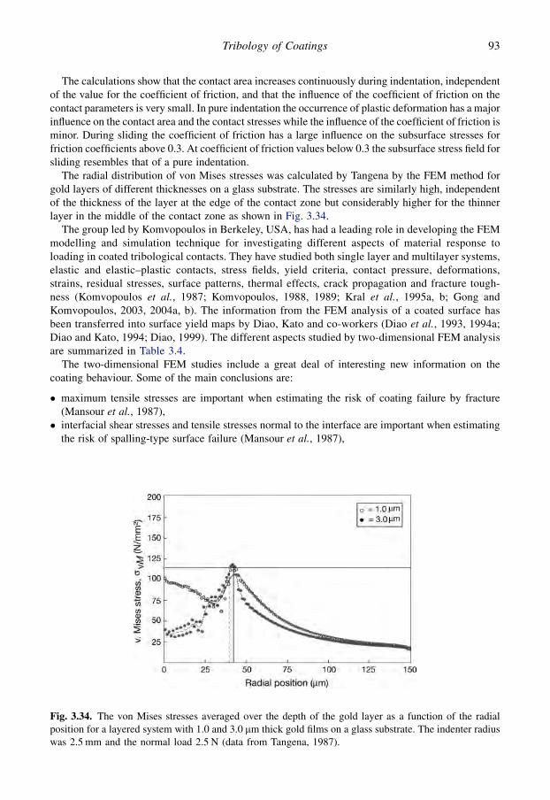
The calculations show that the contact area increases continuously during indentation, independentof the value for the coefficient of friction, and that the influence of the coefficient of friction on thecontact parameters is very small. In pure indentation the occurrence of plastic deformation has a majorinfluence on the contact area and the contact stresses while the influence of the coefficient of friction isminor. During sliding the coefficient of friction has a large influence on the subsurface stresses forfriction coefficients above 0.3. At coefficient of friction values below 0.3 the subsurface stress field forsliding resembles that of a pure indentation.
The radial distribution of von Mises stresses was calculated by Tangena by the FEM method forgold layers of different thicknesses on a glass substrate. The stresses are similarly high, independentof the thickness of the layer at the edge of the contact zone but considerably higher for the thinnerlayer in the middle of the contact zone as shown in Fig. 3.34.
The group led by Komvopoulos in Berkeley, USA, has had a leading role in developing the FEMmodelling and simulation technique for investigating different aspects of material response toloading in coated tribological contacts. They have studied both single layer and multilayer systems,elastic and elastic–plastic contacts, stress fields, yield criteria, contact pressure, deformations,strains, residual stresses, surface patterns, thermal effects, crack propagation and fracture tough-ness (Komvopoulos et al., 1987; Komvopoulos, 1988, 1989; Kral et al., 1995a, b; Gong andKomvopoulos, 2003, 2004a, b). The information from the FEM analysis of a coated surface hasbeen transferred into surface yield maps by Diao, Kato and co-workers (Diao et al., 1993, 1994a;Diao and Kato, 1994; Diao, 1999). The different aspects studied by two-dimensional FEM analysisare summarized in Table 3.4.
The two-dimensional FEM studies include a great deal of interesting new information on thecoating behaviour. Some of the main conclusions are:
� maximum tensile stresses are important when estimating the risk of coating failure by fracture(Mansour et al., 1987),� interfacial shear stresses and tensile stresses normal to the interface are important when estimating
the risk of spalling-type surface failure (Mansour et al., 1987),
Fig. 3.34. The von Mises stresses averaged over the depth of the gold layer as a function of the radialposition for a layered system with 1.0 and 3.0 mm thick gold films on a glass substrate. The indenter radiuswas 2.5 mm and the normal load 2.5 N (data from Tangena, 1987).
93Tribology of Coatings

Table 3.4. Finite element method (FEM) studies of the contact problem with layered surfaces (E¼ elastic, P¼ plastic, R¼ rigid)
Reference 2 DFEM
3 DFEM
Coating Sub-strate
Counterface Singlelayer
Multilayers
Multi-contacts
Contactpressure
Stressdistrib.
Modelledcoating/substratematerials
Mansour et al. (1987) X E E E X XTangena (1987); Tangenaand Wijnhoven (1988)
X EP EP R X X X X Gold/glass CoAu/Ni/Cu
Komvopoulos et al. (1987) X E E R X TiN/Ti and steelKomvopoulos (1988, 1989) X E and EP E and EP R X X XDjabella and Arnell (1992,1993a, b, c)
X E E E X X
Diao et al. (1993, 1994); Diaoand Kato (1994); Diao (1999)
X EP EP E X X X X
Kral et al. (1995a) X EP EP R X X X XKral et al. (1995b) X EP EP R X X XKral and Komvopoulos (1996a) X EP EP R X X XKral and Komvopoulos (1996b) X EP EP R X X X XRabinovich and Sarin (1996) X EP EP R X X TiC/WC–CoWong and Kapoor (1996) X EP EP R X XKral and Komvopoulos (1997) X EP EP R X XBell et al. (1998) X EP EP R X TiN/HSSStephens et al. (2000) X E EP E X X X DLC/Ti–6Al–4V alloySouza et al. (2001) X E EP R X XXiaoyu et al. (2001) X E EP R X X TiN/HSSXiaoyu et al. (2002) X E EP R X TiN, Al, polymer/steel,
Al, polymer, glassGong and Komvopoulos (2003) X EP EP R X X XHolmberg et al. (2003) X E EP R X X TiN/high-speed steelYe and Komvopoulos (2003a) X EP EP R X XYe and Komvopoulos (2003c) X EP EP E X X X Carbon/magnetic layerGong and Komvopoulos (2004a) X E EP R X X X
94
Co
atin
gs
Trib
olo
gy

Gong and Komvopoulos (2004b) X E EP R X X X Pyrolitic carbon/ graphiteLindholm et al. (2006) X E E E X XHolmberg et al. (2006a, b) X E EP R X X TiN/high-speed steelLi and Beres (2006) X EP EP R X X TiN/Ti–6Al–4VLaukkanen et al. (2006) X E EP R X X TiN/high-speed steelPanich and Sun (2006) X EP EP R X X TiB2/HSSDick et al. (2006a) X EP E E X X Composite layerFukumasu et al. (2006) X E EP R X X 2-component substrateTilbrook et al. (2007) X EP EP R X TiN/metalJungk et al. (2008) X EP EP R X DLC/metalHolmberg et al. (2008c) X E EP R X X TiN and DLC/HSS
Reference Misesyield stress
Deformations Strain Residualstress
Thermalanalysis
Surfacepattern
Defects Crackgrowth
K/SIF m Comment
Mansour et al. (1987)Tangena (1987); Tangenaand Wijnhoven (1988)
X X X X 0–1 Wear modelling
Komvopoulos et al. (1987) X X 0–0.5 LubricatedKomvopoulos (1988, 1989) X X X 0–0.5Djabella and Arnell (1992,1993a, b, c)
0–0.5
Diao et al. (1993, 1994); Diaoand Kato (1994); Diao (1999)
X 0–0.7 Yield map
Kral et al. (1995a) X 0 IndentationKral et al. (1996b) X X 0 IndentationKral and Komvopoulos (1996a) X X X 0.1 Shakedown effectKral and Komvopoulos (1996b) X X X 0.1/0.25Rabinovich and Sarin (1996) X Scratch testWong and Kapoor (1996) X 0.1–0.5 Shakedown limitKral and Komvopoulos (1997) X X X 0.1/0.25Bell et al. (1998) X XStephens et al. (2000) X 0–0.5 Graded substrateSouza et al. (2001) X X Indentation
(Continued)
95
Trib
olo
gy
of
Co
atin
gs

Table 3.4. Continued
Reference Misesyield stress
Deformations Strain Residualstress
Thermalanalysis
Surfacepattern
Defects Crackgrowth
K/SIF m Comment
Xiaoyu et al. (2001) X X 0–0.8 Coatingdetachment,Scratch test
Xiaoyu et al. (2002) 0.2 Scratch testGong and Komvopoulos (2003) X X X 0.1/0.5Holmberg et al. (2003) X X 0.08 Scratch testYe and Komvopoulos (2003a) X X X 0–0.5Ye and Komvopoulos (2003c) X X X 0.5 Frictional heatingGong and Komvopoulos (2004a) X X X X 0.5 Frictional heatingGong and Komvopoulos (2004b) X X X X 0.1/0.5Lindholm et al. (2006) XHolmberg et al. (2006a, b) X X 0.08 Scratch testLi and Beres (2006) X 0.26 Scratch testLaukkanen et al. (2006) X X X 0.08 Scratch testPanich and Sun (2006) X Scratch testDick et al. (2006a) X X 0.1–0.5 FrettingFukumasu et al. (2006) X XTilbrook et al. (2007) X X X XJungk et al. (2008) X XHolmberg et al. (2008c) 0.05 and
0.07
96
Co
atin
gs
Trib
olo
gy
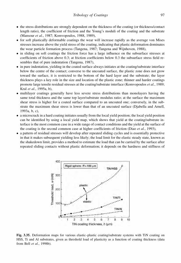
� the stress distributions are strongly dependent on the thickness of the coating (or thickness/contactlength ratio), the coefficient of friction and the Young’s moduli of the coating and the substrate(Mansour et al., 1987; Komvopoulos, 1988, 1989),� for soft plastically deformable coatings the wear will increase rapidly as the average von Mises
stresses increase above the yield stress of the coating, indicating that plastic deformation dominatesthe wear particle formation process (Tangena, 1987; Tangena and Wijnhoven, 1988),� in sliding on soft coatings the friction force has a large influence on the subsurface stresses at
coefficients of friction above 0.3; at friction coefficients below 0.3 the subsurface stress field re-sembles that of pure indentation (Tangena, 1987),� in pure indentation, yielding in the coated surface always initiates at the coating/substrate interface
below the centre of the contact; converse to the uncoated surface, the plastic zone does not growtoward the surface, it is restricted to the bottom of the hard layer and the substrate; the layerthickness plays a key role in the size and location of the plastic zone; thinner and harder coatingspromote large tensile residual stresses at the coating/substrate interface (Komvopoulos et al., 1989;Kral et al., 1995a, b),� multilayer coatings generally have less severe stress distributions than monolayers having the
same total thickness and the same top layer/substrate modulus ratio; at the surface the maximumshear stress is higher for a coated surface compared to an uncoated one; conversely, in the sub-strate the maximum shear stress is lower than that of an uncoated surface (Djabella and Arnell,1993a, b, c),� a microcrack in a hard coating initiates usually from the local yield position; the local yield position
can be identified by using a local yield map, which shows that yield at the coating/substrate in-terface is the most common case in a wide range of contact conditions and the yield at the surface ofthe coating is the second common case at higher coefficients of friction (Diao et al., 1993),
� a pattern of residual stresses will develop after repeated sliding cycles and is essentially protectivein that it makes subsequent yielding less likely; the load limit for the elastic steady state, known asthe shakedown limit, provides a method to estimate the load that can be carried by the surface afterrepeated sliding contacts without plastic deformation; it depends on the hardness and stiffness of
Fig. 3.35. Deformation maps for various elastic–plastic coating/substrate systems with TiN coating onHSS, Ti and Al substrates, given as threshold load of plasticity as a function of coating thickness (datafrom Bell et al., 1998b).
97Tribology of Coatings
the coating and the substrate, the coating thickness and the coefficient of friction (Wong andKapoor, 1996),� deformation maps, with the threshold load for plasticity as a function of coating thickness, can be
developed for designers to assist in selection of coating thickness and substrates to meet specificloading conditions, as shown in Fig. 3.35 (Bell et al., 1998b),� a coating substrate system with an appropriate gradient in substrate yield strength can withstand
significantly higher applied contact stresses, shift the location of the initial yield point deeper intothe substrate, and coatings of greater thickness can be used; an appropriate gradient in Young’smodulus results in a dramatic reduction in equivalent stress on the contact surface and the interfaceas compared to a non-graded one; the initial yielding in a graded substrate is largely independent ofthe coating thickness, friction coefficient and Young’s modulus; the initial yield point remains wellbelow the coating/substrate interface, decreasing the possibility of coating detachment due toexcessive strain at the interface (Stephens et al., 2000),� maximum contact pressure is a strong function of surface topographical pattern; patterned surfaces
produce higher tensile stresses but lower plastic strains and smaller plastic zones than flat surfacesas the surface can store significant strain energy without undergoing plastic deformation (Gong andKomvopoulos, 2003),� surface cracking in a multilayer surface containing a crack perpendicular to the free surface due to
repetitive sliding of a rigid asperity is controlled by the tensile fracture mode as the stress intensityfactor KI is considerably higher than KII; higher friction at the sliding contact region increases bothKI and KII significantly; the increase of friction at the crack interface promotes stress relaxation;initial crack growth was found to occur at an angle of ~10� from the original crack plane, in-dependent of the initial crack length; after the first few crack growth increments the crack growthpaths are almost parallel to each other, exhibiting a common deviation from the original crack planeby 57� (Gong and Komvopoulos, 2004b).
3.2.8.3 Coated surfaces in three dimensions
FEM modelling can be carried out with a very complex finite element mesh; the more complex it is,the more detailed information can be achieved. The drawback with complex meshes is that they resultin very long computing times. So the optimal solution is always a balance between the complexity ofthe mesh and minimizing of the computing time. Nonetheless, the rapid development in computingcapacity and speed offers a possibility to run even relatively complex three-dimensional FEM meshesin a reasonable time. Three-dimensional FEM is important especially when the stress fields of otherthan line contacts are studied since stress maxima will be found also outside the vertical plane ofsymmetry that is studied by 2D FEM. An example of such a contact is a coated flat contact slidingagainst a spherical counterface.
The group of Komvopoulos used 3D FEM to study the contact of a rigid sphere sliding on anelastic–plastic coated surface in both a single contact and repeated sliding. They described theshakedown effect, real stresses and von Mises stresses, deformations and strains, residual stresses,reyielding during unloading, the evolution of plasticity, and thermomechanical and topographyeffects (Kral and Komvopoulos, 1996a, b, 1997; Ye and Komvopoulos, 2003a, c; Gong andKomvopoulos, 2004a).
It is interesting to model the coated surface when sliding against a spherical diamond, as ina scratch test device, as shown in Fig. 3.36, since the configuration with an increasing load shows theevolution of the stress and strain fields at different loads. Three effects are important to consider withregards to the fracture behaviour of the coating. They are the ploughing of the spherical stylusresulting in plastic deformation, the sliding of the stylus on the coating resulting in friction and fromthis the pulling force on the coating behind the contact resulting in tensile stresses and fracture(Holmberg et al., 2003).
98 Coatings Tribology

A detailed analysis of the contact conditions is needed for accurate FEM stress measurements.Holmberg et al. (2006a) investigated the contact of a rigid sphere sliding on an elastic–plasticsubstrate coated with a hard elastic coating, correlating with the conditions of a thin ceramic coatingon a steel substrate. The complex stress field in the surface is formed as a result of the following foureffects, see Fig. 3.37:
1. Friction force. The friction force between the sliding stylus and the surface generates compres-sional stresses in front of the stylus originating from the pushing action, and tensional stressesbehind the tip originated from the pulling.
2. Geometry changes. The elastic and plastic deformations are spherical indent, groove and torusshaped. They result in bending, stretching and compressing of the coating. The stresses arising areboth compressive and tensile.
3. Bulk plasticity concentration. The spherical indentation causes the hard coating to deform elas-tically in a circular wave-like shape and the substrate under the coating to deform plastically,reaching its peak value at an angle of about 45� from the plane of symmetry in the plane of thecoating. This can be identified with local minima and maxima of deformation between the tensilestress peaks around the indenter (at locations of 0 and 90�, respectively).
4. Residual stresses. It is very common that especially thin ceramic coatings, due to the depositionprocess, contain even very considerable compressive residual stresses. These are typically of theorder of 0.5–4 GPa but values even as high as 10 GPa may appear, see section 3.2.10.
The bulk plasticity effect can be illustrated by the similarity with the situation experienced whena piece of paper is placed over a soft substrate, e.g. the hand, and pressed down at one point with
Fig. 3.36. Schematic illustration of the scratch tester spherical stylus drawn along the coated surface. Thematerial loading and response can be divided into three phases: ploughing, interface sliding and pullingthe coating.
99Tribology of Coatings

a finger. The paper will respond with a circular wave-like shape around the finger. If the paper wasglued to the hand it would generate stresses and strains on the skin accordingly.
The contact conditions of a 200 mm radius diamond stylus sliding 10 mm with a load increasingfrom 5 N to 50 N and indentation depth increasing from 0.5 mm to 3 mm, over a 2 mm thick TiNcoating attached with complete adhesion to a high-speed steel substrate was modelled by 3D FEMby Holmberg et al. (2003, 2006a). For the adhesive component of the coefficient of friction theyused the measured value 0.08. The friction originating from ploughing is integrated as plasticdeformation in the FEM model. The stylus was modelled as linear elastic but with Young’s modulusof a diamond it will behave practically as rigid. The ceramic TiN coating was assumed not todeform plastically and thus modelled as linear–elastic. The high-speed steel substrate was modelledas elastic–plastic including the strain hardening effect. A schematic illustration of the FEM mesh isshown in Fig. 3.38.
Holmberg and co-workers were interested in investigating the fracture behaviour of the hardcoating and thus they primarily analyse and infer the FEM stress calculations with respect to firstprincipal stress, which is defined as the largest stress in tension in any direction. The frequently usedvon Mises stress is not usually associated with brittle failure and has its greatest potential in un-derstanding and modelling deformation-related events such as plasticity of metals. Topographicalstress field maps showing the first principal stresses on the top of the coating and at the subsurfacesymmetry plane in the direction of sliding at four different positions are shown in Figs 3.39a–d.
The topographical stress field maps illustrate the following effects. In these loading conditionsthere are:
Fig. 3.37. The stress field in the coated surface resulting from a sliding sphere is a result of four loadingeffects: friction force, geometrical deformations, bulk plasticity concentration and residual stresses.Illustration (a) shows the loading effects with exaggerated dimensions and deformations and (b) withcorrect dimension interrelationships.
100 Coatings Tribology

Fig. 3.38. Schematic illustration of the three-dimensional finite element mesh. The mesh sizing is in therange of 0.25–100 mm and the number of mesh nodes is about 190,000.
a b
c d
Fig. 3.39. Topographical stress field maps showing first principal stresses on the top of the coating and atthe symmetry plane intersection of a high-speed steel sample coated with a 2 mm thick TiN coating andloaded by a sliding spherical diamond stylus. Sliding direction is from left to right, the sliding stylus isinvisible in the figure and the contact zone is indicated by the white curve. The values on the colour scaleare given in MPa. Stress fields shown are at (a) 5 N pre-load and 0.5 mm indentation depth without sliding,(b) 5.3 N load and 0.06 mm sliding, (c) 10 N load and 1.2 mm sliding and (d) 20 N load and 3.3 mmsliding. See Appendix B for coloured figure.
101Tribology of Coatings

� fairly high tensional stresses, about 1150 MPa, at the top of the surface around the stylus(Fig. 3.39a),
� stress minima down to zero MPa at about 45� and 135� from the symmetry plane originating fromthe bulk plasticity concentration (Fig. 3.39a),
� high, about �2100 MPa, compressive stresses right under the stylus, and tensile stresses, about400 MPa, some 20 mm under the stylus (Fig. 3.39a),
� residual stresses, about 2000 MPa, on the remaining indent after some sliding (Fig. 3.39b),� high residual stresses, about 2000 MPa, in the groove formed behind the sliding stylus
(Fig.3.39c),� tensile stress maxima, about 2100 MPa, about 15 mm behind the back edge of the contact area and
about 10 mm on the left side of the symmetry plane (Fig. 3.39c); this is especially interesting since thefirst angular cracks observed empirically in similar conditions appear exactly at this location,� movement of the compressive stress maxima from the top of the coating right under the sliding
stylus (Fig. 3.39a) to a depth of about 15 mm below the surface (Fig. 3.39d); this illustrates thecompensation of the compressive stresses in the coating by tensile stresses from the coatingstretching due to substrate deformation, and� high tensile stresses, about 3000 MPa, behind the sliding stylus (Fig. 3.39d); these are, however,
overestimated since in the real conditions they will partly be released by the formed crack field.
The finite element method can be used to analyse tribological mechanisms in surfaces even down tothe nanolevel. Holmberg et al. (2008b) have studied the influence of 100 and 500 nm thick bond layersbetween a 2 mm thick coating and the substrate and used an FEM model with nod density down to25 nm. They showed the rapid changes in the interface region stresses under the sliding contact ina scratch test and how these are influenced by the elasticity and thickness of the bond layer.
The three-dimensional FEM stress and strain analyses of coated surfaces have also bought muchnew understanding and some of the main conclusions are listed below. The conclusions are presentedin a more generalized form and reflect typically the situation when a sphere slides over a plasticsubstrate covered with a harder coating:
� main mechanisms generating stresses and strain in a loaded coated surface are: friction, surfacegeometrical changes, bulk plasticity concentration, residual stresses, thermal effects, topographyeffects (Kral and Komvopoulos, 1996a, b, 1997; Ye and Komvopoulos, 2003a, c; Gong andKomvopoulos, 2004a; Holmberg et al., 2006a),� bulk plasticity concentration effects result in a tetra arm-shaped tensile stress pattern on the coating
around the counterface when a sphere is sliding on a substrate covered with a harder coating(Holmberg, 2003; Li and Beres, 2006),� the first coating crack in the total stress field volume is generated at the top surface of the coating
behind the sliding counterface at the groove edge and grows downward (Holmberg et al., 2003,2006a; Laukkanen et al., 2006),� a hard coating on a softer substrate is carrying part of the load and decreasing the stresses in the
substrate (Kral and Komvopoulos, 1996b; Holmberg et al., 2006a),� high residual tensile stresses are formed in the coating on the groove behind the slider (Xiaoyu
et al., 2002; Holmberg et al., 2006a; Li and Beres, 2006),� there is a pile up effect of material generated from compression in front of a slider that results in
high tensile stresses on the surface; the maximum forward flow at the contact surface increaseprimarily with friction and decreasing stiffness and hardness of the coating and secondarily withnormal load (Kral and Komvopoulos, 1996a, b; Xiaoyu et al., 2002; Holmberg et al., 2006b; Li andBeres, 2006),� Young’s modulus and coating thickness are principal parameters affecting the magnitude of stresses
in a loaded soft substrate covered with a hard coating (Holmberg et al., 2006b),
102 Coatings Tribology

� a thicker hard coating has a better load-carrying capacity than a thinner one but generates higherstresses at the coating/substrate interface (Holmberg et al., 2006b),� a stiffer coating (high E modulus) has a better load-carrying capacity than a more compliant one
(low E modulus) but generates higher tensile stresses in the coating and lower tensile stresses in thesubstrate with the same indentation depth (Kral and Komvopoulos, 1996b, 1997; Holmberg et al.,2006b),� maximum first principal stress in the coating due to loaded sliding increases, respectively de-
creases, with increasing tensile, respectively compressive, residual stress in the coating; in high-friction sliding, plasticity in the substrate is affected predominantly by the coefficient of friction andsecondarily by the residual stress (Ye and Komvopoulos, 2003a),� residual compressional stresses in a hard coating increase both the maximum tensile stresses at the
top of the coating and compressional stresses in the coating right under the sliding counterface(Laukkanen et al., 2006),
� residual stresses existing in the coating are relaxed by the deformations taking place under a loadedsliding counterface and will have little influence on crack formation in the groove behind the slider(Laukkanen et al., 2006),� reyielding in the substrate may occur at unloading; it may also occur after a second sliding cycle for
a highly loaded sliding contact and result in a larger plastic zone than is produced in the first loadcycle (Kral and Komvopoulos, 1996a, 1997),� the maximum plastic strain arises in the subsurface region slightly behind the centre of the contact
area at low friction while at high friction it occurs on the surface within the contact area (Kral andKomvopoulos, 1997),� high-friction sliding promotes plasticity and intensifies the von Mises and first principal stresses in
both the coating and the substrate, thus increasing the tendency for yielding and cracking in each ofthem (Ye and Komvopoulos, 2003a),� coating thickness exhibits a more pronounced effect on the temperature rise from frictional heating
at the coating surface and the coating/substrate interface than the layer thermal conductivity;frictional heating and shear surface traction may intensify the stress field significantly; the likeli-hood of yielding and cracking in the coated surface increases with decreasing coating thickness (Yeand Komvopoulos, 2003c),� a patterned coated surface results in reduced plastic deformation in the substrate compared to
a smooth surface (Gong and Komvopoulos, 2004a), and� when a bond layer is used, e.g. for coating/substrate adhesion improvement, should the bond layer
be less stiff than the coating then high and critical tensile stresses will not be generated; thethickness of the bond layer may vary and is normally not critical with respect to generated stressesin the surface (Holmberg et al., 2008b).
3.2.8.4 The E/H relationship
The FEM analyses aim to consider the whole parameter space influencing friction and wear ina coated contact. Another approach is to focus on some dominating parameters to easily obtain someinformation on the tribological behaviour of the coated surface. One such approach is to calculate theE/H or H/E relationship for a contact. It is commonly known that the hardness, H, of a material is oftenstrongly related to wear and also to friction. However, the elastic property represented by Young’smodulus, E, is often neglected even if it also has an important influence in many contact conditions.Thus is it very relevant to study these two parameters together.
It was pointed out many years ago by Oberle (1951) that in a sliding contact, wear of an engineeringmaterial is closely related to the elastic limit of strain of the material. A practical measure of the elasticlimit of strain is the H/E relationship. Halling and Arnell (1984) used this relationship to evaluate the
103Tribology of Coatings

elastic contact of a rough surface. They used the ratio E0/H, were E0 combines Young’s modulus valuesof both mating surfaces and found that this ratio is related to the wear resistance of the two surfaces.
This approach can be applied to a coated surface as discussed by Matthews and Leyland (2000,2002) and Leyland and Matthews (2000). They reiterate that the ratio HC/EC, where HC and EC are thehardness and Young’s modulus of the coating, defines the material’s elastic strain limit, that is theamount by which the coating can be stretched before permanent deformation occurs. This gives anindication of the ability of the film to deform with the substrate under load without yielding. Mini-mization of EC/HC will ensure that plastic deformation and wear can be avoided and the ploughingcomponent in friction is reduced, as shown by Gupta and Meletis (2004) and Ni et al. (2004a). Acomparison of the E/H values of the coating and the substrate gives an indication of the amount ofplastic deformation occurring in the coating and in the substrate, respectively (Korunsky et al., 1998;Komvopoulos et al., 2004).
The ratio H/E is also part of the plasticity index (Greenwood and Williamson, 1966). The im-portance of the H/E ratio has been known by bearing designers for many years. They routinely usethe plasticity index when determining the degree of polish required by a bearing surface to ensure thatsurface asperity deformation under load is avoided.
The ratio HC3/EC
2, called the plastic resistance parameter, has been theoretically derived from thematerial behaviour and used as an indicator of the resistance to plastic flow of the coating (Tsui et al.,1995; Mayrhofer et al., 2003; Musil, 2005; Musil and Jirout, 2007).
3.2.9 Influence of surface roughness
All surfaces we deal with in our daily life are rough and the roughness influences the contact andsubsurface stresses in a loaded contact. This influence depends very much on whether the asperitiesare deformed elastically or plastically. The mode of asperity deformation also influences the realcontact area and thus the friction and wear (Halling, 1975, 1986). When the asperities are deformedplastically the load is linearly related to the real area of contact for any distribution of asperity heights.When the asperities deform elastically, linearity between load and real area of contact will occur onlywhen the asperity distribution is exponential, which is common for practical surfaces.
The influence of surface roughness on surface and subsurface stresses and other contact parameters issmall if the asperities are deformed plastically, as is often the case for soft coatings (Tangena, 1987).Ogilvy (1992, 1993) showed by numerical simulation how the average contact pressure across all contact
Fig. 3.40. Contact pressure distribution for a smooth uncoated surface loaded by a smooth cylinder (Hertziandistribution) and by a rough cylinder with Ra¼ 0.44 mm and pHz¼ 2.2 GPa (after Sainsot et al., 1990).
104 Coatings Tribology
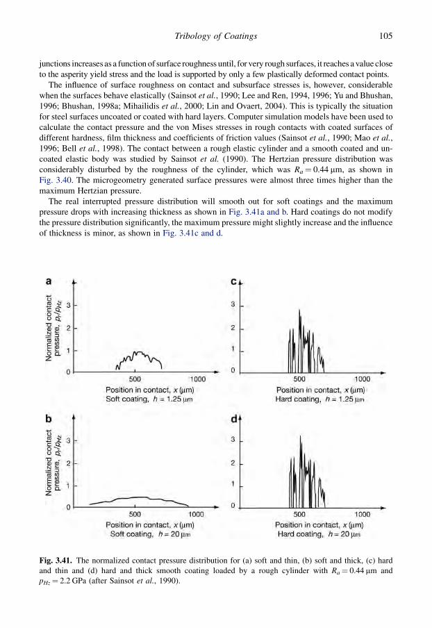
junctions increases as a function of surface roughness until, for very rough surfaces, it reaches a value closeto the asperity yield stress and the load is supported by only a few plastically deformed contact points.
The influence of surface roughness on contact and subsurface stresses is, however, considerablewhen the surfaces behave elastically (Sainsot et al., 1990; Lee and Ren, 1994, 1996; Yu and Bhushan,1996; Bhushan, 1998a; Mihailidis et al., 2000; Lin and Ovaert, 2004). This is typically the situationfor steel surfaces uncoated or coated with hard layers. Computer simulation models have been used tocalculate the contact pressure and the von Mises stresses in rough contacts with coated surfaces ofdifferent hardness, film thickness and coefficients of friction values (Sainsot et al., 1990; Mao et al.,1996; Bell et al., 1998). The contact between a rough elastic cylinder and a smooth coated and un-coated elastic body was studied by Sainsot et al. (1990). The Hertzian pressure distribution wasconsiderably disturbed by the roughness of the cylinder, which was Ra¼ 0.44 mm, as shown inFig. 3.40. The microgeometry generated surface pressures were almost three times higher than themaximum Hertzian pressure.
The real interrupted pressure distribution will smooth out for soft coatings and the maximumpressure drops with increasing thickness as shown in Fig. 3.41a and b. Hard coatings do not modifythe pressure distribution significantly, the maximum pressure might slightly increase and the influenceof thickness is minor, as shown in Fig. 3.41c and d.
Fig. 3.41. The normalized contact pressure distribution for (a) soft and thin, (b) soft and thick, (c) hardand thin and (d) hard and thick smooth coating loaded by a rough cylinder with Ra¼ 0.44 mm andpHz¼ 2.2 GPa (after Sainsot et al., 1990).
105Tribology of Coatings

When the load distribution is known, the subsurface stresses can be calculated. The von Misesstress distribution of the uncoated rough contact referred to earlier (Fig. 3.40) is shown in Fig. 3.42.The roughness of the surface generates some stress perturbations near the surface of the loadedcontact. These stress maxima perturbations are often at about the same depth from the surface aswhere the coating/substrate interface occurs in coated surfaces and thus their influence on interfacestresses is important.
Fig. 3.42. Von Mises stresses in a smooth uncoated surface loaded by a rough cylinder with Ra¼ 0.44 mmand pHz¼ 2.2 GPa (after Sainsot et al., 1990).
Fig. 3.43. Von Mises stresses in (a) soft and thin, (b) soft and thick, (c) hard and thin and (d) hard and thicksmooth surface loaded by a rough cylinder with Ra¼ 0.44 mm and pHz¼ 2.2 GPa (after Sainsot et al., 1990).
106 Coatings Tribology
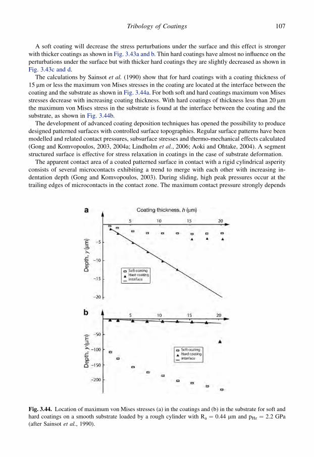
A soft coating will decrease the stress perturbations under the surface and this effect is strongerwith thicker coatings as shown in Fig. 3.43a and b. Thin hard coatings have almost no influence on theperturbations under the surface but with thicker hard coatings they are slightly decreased as shown inFig. 3.43c and d.
The calculations by Sainsot et al. (1990) show that for hard coatings with a coating thickness of15 mm or less the maximum von Mises stresses in the coating are located at the interface between thecoating and the substrate as shown in Fig. 3.44a. For both soft and hard coatings maximum von Misesstresses decrease with increasing coating thickness. With hard coatings of thickness less than 20 mmthe maximum von Mises stress in the substrate is found at the interface between the coating and thesubstrate, as shown in Fig. 3.44b.
The development of advanced coating deposition techniques has opened the possibility to producedesigned patterned surfaces with controlled surface topographies. Regular surface patterns have beenmodelled and related contact pressures, subsurface stresses and thermo-mechanical effects calculated(Gong and Komvopoulos, 2003, 2004a; Lindholm et al., 2006; Aoki and Ohtake, 2004). A segmentstructured surface is effective for stress relaxation in coatings in the case of substrate deformation.
The apparent contact area of a coated patterned surface in contact with a rigid cylindrical asperityconsists of several microcontacts exhibiting a trend to merge with each other with increasing in-dentation depth (Gong and Komvopoulos, 2003). During sliding, high peak pressures occur at thetrailing edges of microcontacts in the contact zone. The maximum contact pressure strongly depends
Fig. 3.44. Location of maximum von Mises stresses (a) in the coatings and (b) in the substrate for soft andhard coatings on a smooth substrate loaded by a rough cylinder with Ra ¼ 0.44 mm and pHz ¼ 2.2 GPa(after Sainsot et al., 1990).
107Tribology of Coatings

on the pattern geometry. The maximum tensile residual stress on a coating with a sinusoidal surfacepattern occurs at the trailing edge of the contact region. This stress is much higher than that obtainedwith a flat coated surface and depends on the pattern geometry and the coefficient of friction. Ina patterned coated surface with a high amplitude-to-wavelength ratio and high friction, a significanttensile residual stress is generated in the groove behind the contact. Patterned surfaces produce lowerplastic strains and smaller plastic zones than flat surfaces due to the lower stresses resulting from theincreased compliance of the coating that can store strain energy without undergoing plastic de-formation. The decreased surface stiffness of a hard patterned coated surface reduces the maximumplastic strain and size of the plastic zone in the substrate. However, this results in a higher surfacetensile stress at the trailing edge of the contact interface, creating a greater risk of surface crackinitiation in the patterned surface.
Contact fatigue of a coated surface with an elastic surface coating on the top of three elastic–plasticunderlying coatings in sliding contact with a rigid and rough surface was analysed by FEM by Gongand Komvopoulos (2005). The rough surface was characterized by scale-invariant fractal geometry inorder to include multiscale roughness effects and self-affine surface features. The critical segment ofthe rough surface was identified and used for contact fatigue simulations. They showed that a tran-sition from tensile to shear dominant mode of fatigue crack growth occurs as the crack tip approachesthe interface. This results in further crack growth almost parallel to the layer interface. The resultsshow the importance of surface roughness in the contact fatigue of coated surfaces.
Detailed analysis of tribology-related effects in contacts with rough surfaces has been reported byBhushan and co-workers (Yu and Bhushan, 1996; Bhushan, 1998a, 1999b).
3.2.10 Residual stresses
A residual stress is a stress in the surface that for some reason cannot be relaxed and thus remains inthe surface even when no external load is present. A coated surface generally contains residualstresses that are either a result of intrinsic changes in the structure due to the deposition process ordeformations, or a result of mismatch in thermal expansion at temperature changes. The residualstresses are normally in the range of 0.1 to 4 GPa in compression, but can sometimes be very high, upto 10 GPa in compression and up to a few GPa in tension. The stresses due to temperature changes arecalled thermal stresses and those due to structural changes are called intrinsic stresses. Both arediscussed in more detail below. The residual stresses can be divided into four categories, as shown inTable 3.5 (Holmberg et al., 2008d).
Most ceramic coatings are improved tribologically by high compressive residual stresses parallel tothe surface. The compressive stresses in coatings on flat surfaces inhibit crack initiation and crackgrowth. Tensile stresses, on the other hand, tend to promote crack growth and are not desired(Bower and Fleck, 1994; Eberhardt and Peri, 1995; Bromark, 1996; Gunnars and Alahelisten, 1996;Nordin, 2000; Zoestbergen and De Hosson, 2002; Cammarata, 2004). High compressive stresses may
Table 3.5. Categories of residual stresses.
Residual stresses Deposition process induced Sliding induced
Thermal stress due to mismatch in thermalexpansion of coating and substrateafter temperaturechange from deposition to ambient.
due to mismatch in thermal expansionof coating and substrate fromtemperature change originating fromfrictional heating.
Intrinsic stress due to defects built into coatingduring deposition.
due to strains created by deformation.
108 Coatings Tribology

result in decohesion and delamination at edges or corners or when the coating is deposited on roughsurfaces. This is illustrated in Fig. 3.45.
Generally, coatings, which are thin with respect to the interface topography, are less sensitive toresidual stress-induced failure. The critical interface stress state becomes independent of the coatingthickness if the coating is thicker than about three times the amplitude of the interface roughness.Coating/substrate interfacial stresses of about half the magnitude of the residual stresses in the coatingare induced at corners, edges and topographical irregularities. The highest value of the interfacialstress is obtained for a coating thickness equal to the minimum radius of the surface contour (Wiklundet al., 1999b).
A mechanism explaining the level of residual compressive stresses needed to inhibit crack prop-agation in a diamond coating has been proposed by Gunnars and Alahelisten (1996). At the beginningof the wear process the protruding grains will take up the externally applied stresses, as shown inFig. 4.53. The result is that high local stress concentrations and fragmentation occur. The residualstresses are low in the protruding grains since the geometry permits relaxation. A crack nucleated ina protruding grain will propagate preferentially along easy cleavage planes. However, a crack thatpropagates deeper into the coating will encounter higher and higher compressive residual stresseswhich will deflect the crack into a path, irrespective of cleavage planes. The large residual stresses willprevent cracks initiated at the surface from propagating towards the interface and will thus promotecrack paths parallel to the surface.
An idealized representation of the total stress generated in a thin film as a function of the parameterT/Tm, where T (K) is the substrate temperature and Tm is the coating material melting temperature, isshown in Fig. 3.46. The intrinsic stress is assumed to be tensile by Thornton and Hoffman (1989),although it must be remembered that this is not typical for ceramic tribological coatings on metalsubstrates produced by PVD. The deposition temperature is assumed to be greater than the finalmeasurement temperature and the film thermal expansion coefficient is assumed to be greater thanthat of the substrate so that a tensile stress is generated when the substrate is cooled. At low T/Tm theintrinsic stress dominates the thermal stress, whereas at high values the thermal stresses dominate.When the T/Tm exceeds about 0.25, the recovery processes are operative so that the intrinsic com-ponent of the stress is reduced (Thornton and Hoffman, 1989).
Fig. 3.45. Illustration of stresses induced in a coated surface having compressive residual stresses when(a) coated on a flat and smooth surface, (b) coated over an edge, (c) including a pore, (d) in a groove and(e) at a ridge (after Wiklund et al., 1999b).
109Tribology of Coatings

The most common methods for measuring the residual stresses in coated surfaces are those basedon direct measurement of the elastic strains in the film by X-ray diffraction and those based onmeasuring the associated curvature or deflection of a thin substrate (Sue, 1992; Larsson et al., 1996;Borland, 1997; Malzbender et al., 2002; Zoestbergen and De Hosson, 2002; Cammarata, 2004; andPauleau, 2008). Some characteristic residual stress values are given in Table 3.6. Stress relaxation ofcoatings with high residual stresses on flexible substrates can be achieved by using a segmentedstructure where the film is intentionally separated into small segments as if it was full of small regularcracks (Aoki and Ohtake, 2004).
Finite element analysis has been used to investigate the influence of residual stresses on the stressand strain field in coated surfaces (Ye and Komvopoulos, 2003a; Laukkanen et al., 2006). The stresssimulations show that the maximum first principal stress in the coating due to sliding decreases withincreasing compressive residual stress. The residual stress effect on the first principal stress is rela-tively less pronounced in high-friction sliding. The tendency for yielding and cracking at the surfaceand at the coating/substrate interface is strongly affected by the magnitudes of the residual stress andthe coefficient of friction. An optimum residual stress can be determined, depending on the type of theloading, the dominant deformation mode in the coating (i.e. plastic deformation or cracking) and thecoefficient of friction.
Residual compressive stresses of 1 GPa in a 2 mm TiN coating on a steel substrate were found toincrease the maximum tensile stresses on the top of the coating by 10–50% and also increase thecompressive stresses on the surface under the tip to about double in the contact with a sphericaldiamond tip sliding with increasing load from 5 to 20 N over the coated surface (Laukkanen et al.,2006). During sliding of the spherical tip on the surface, the residual stresses in the coating are relaxedunder the tip due to the plastic deformation of the substrate. At the location of appearance of the firstcracks, at the groove edge behind the sliding tip, plastic deformation has already taken place and thecompressive residual stresses have been relaxed. Thus they are not active in hindering the process ofcrack opening due to the concentration of tensile stresses behind the tip.
The stresses and strains that a point on top of the coated surface at the plane of symmetry expe-rience when a sliding spherical tip in a scratch test moves over it are shown in Fig. 3.47 (Holmberget al., 2008d). Starting from left and moving to the right there is first a 1 GPa compressive lateralresidual stress in the coating. Coming closer to the contact zone the compressive stresses increase toabout 5000 MPa right under the tip and then decrease after the contact to zero and even go to close to1000 MPa in tension. After that the stresses level off to a residual level due to inelasticity within the
Fig. 3.46. The thermal and the intrinsic stress contributions as functions of the T/Tm ratio (after Thorntonand Hoffman, 1989).
110 Coatings Tribology

Table 3.6. Example of measured residual stresses in coatings.
Coating/substrate Deposition process Coating thickness (mm) Characteristic residualstress (GPa)
Reference
TiN/Ti–6Al–4V PVD 8.8 �3.7 Sue (1992)TiN/Inconel 718 PVD 8.2 �3.4 Sue (1992)TiN/AISI 304 PVD 8.4 �4.1 Sue (1992)TiN/tool steel PVD 4.1 �3.5 to �4.1 Bromark et al. (1994)TiN/HSS PVD 4�5 �4 Larsson et al. (1996); Wiklund et al. (1999b)TiN/steel �0.2 Komvopoulos (1991a)TiN/Ti 0 Komvopoulos (1991a)TiN/stainless steel PVD 5–7 �6.1 Bull (1997)TiN/CC PVD 3.8 �2.5 Nordin et al. (1999)TiN/CC PVD 4 �4 Wiklund et al. (1999b)TiN/AISI tool steel PVD 2.5–4.4 �4 to �4.5 Zoestbergen et al. (2002)TiAlN/tool steel PVD 3.3 �5 to �6.1 Bromark et al. (1994)Ti(C,N)/AISI tool steel PVD 3.9–4.2 �6.2 to �6.8 Zoestbergen et al. (2002)TiCN/tool steel PVD 3.2 �3.7 to �4.5 Bromark et al. (1994)TiC–C/HSS PVD 1.8–2.6 �0.5 to 7 Wiklund et al. (1999c)CrN/tool steel PVD 4.1 �2.1 to �2.6 Bromark et al. (1994)CrN/tool steel PVD 4 �1 Wiklund et al. (1999b)CrN/CC PVD 4.4 �0.3 Nordin et al. (1999)Cr2O3/Cr/steel �1 Komvopoulos (1991a)Al2O3/Al �3 Komvopoulos (1991a)Al2O3/alloy MA956 Oxide surface 5 �3.7 to �3.9 Bull(1997)TiB2/stainless steel PVD 2 �10 Wiklund et al. (1999b)TiB2/? �6.8 Berger et al. (2000)TiC/CC CVD 4 þ0.2 Wiklund et al. (1999b)
(Continued)
11
1T
ribo
log
yo
fC
oa
ting
s

Table 3.6. Continued
Coating/substrate Deposition process Coating thickness (mm) Characteristic residualstress (GPa)
Reference
Ti/ 0 Berger et al. (2000)W–N/ �1.6 Gachon et al. (1999)DLC/Si �0.5 to 3.6 Kodali et al. (1997)DLC/Si �1.7 to 3.6 Nastasi et al. (1999)DLC a-C/Si PVD 0.4 �12.5 Bhushan (1999a)DLC a-C:H/Si PVD 0.4 �0.6 to �2.0 Bhushan (1999a)DLC/ �1.8 Blug et al. (2001)DLC/ CVD �0.4 to �2 Gupta and Meletis (2004)DLC a-C PVD �0.9 to �2.8 Mounier et al. (1997)DLC a-C PVD �0.1 to �0.9 Mounier et al. (1996)DLC–Si PVD �1 to �3.2 Damasceno et al. (2000)DL(C:H:Si:O)/ �0.5 to �1.4 Scharf et al. (2003b)Diamond/CC CVD 5 � 10 �2 Larsson et al. (1996); Wiklund et al. (1999b)Diamond/ CVD �1.7 to �5.8 Silva et al. (2003)Organic–inorganic film/float glass
Sol-gel spin 2–20 þ0.1 to 0 Malzbender et al. (2000a)
MultilayersTiN/CrN/CC PVD 3.3 �2.1 Nordin et al. (1998)TiN/CrN/CC PVD 2.5–5 �1.3 to �3.2 Nordin et al. (1999)TiN/MoN/CC PVD 3.5 �6.1 Nordin et al. (1998)TiN/NbN/CC PVD 2.9 �1.1 Nordin et al. (1998)TiN/TaN/CC PVD 3.5 �3.1 Nordin et al. (1998)TiN/TaNx PVD 1.0–1.4 þ3.5 to �1.5 Nordin (2000)TiN/TiAlN/AISI PVD 2.8–3.2 �2.5 to �9.7 Zoestbergen et al. (2002)
CC¼ cemented carbide; HSS¼ high-speed steel; –¼ compressive stresses
11
2C
oa
ting
sT
ribo
log
y

substrate. The strains go through similar large changes as shown in the figure. The figure illustrateswell the very radical changes both in stress level and strain that every single point that travels underthe sliding tip experiences. It also shows that due to these changes the 1 GPa compressive residualstresses before the contact will be relaxed and not appear any longer after the contact.
3.2.10.1 Thermal stresses
Thermal stresses are residual stresses that originate from a change in temperature when a coatedsurface is used at a different temperature to that of coating deposition. These are a result of thedifferences in the thermal expansion coefficients of the coating and the substrate. If the coating is thincompared to the substrate, the thermal expansion of the substrate will be relatively unaffected by thepresence of the coating and essentially all mismatch will be accumulated as thermal stresses in thecoating. The difference in temperature can originate from the environment or from the heat generatedin a rubbing contact. The latter is important from a tribological point of view and may even result intemperature differences between the coating and the substrate. The change in stress due to temper-ature change in a coated surface (the thermal stress Dsth) can be calculated from the equation
Dsth ¼ ½DT $ ðas � acÞ $ Ec�=ð1� ncÞ (3.34)
where DT is the temperature change, as and ac are the thermal expansion coefficients of the substrateand the coating, Ec is Young’s modulus for the coating and nc is Poisson’s ratio of the coating (Kramer,1983; Musil, 2005).
The thermal and mechanical consequences of sliding, including heating, friction, deformation andwear, originate within the real area of contact. The contact spots are subject to mechanical loading by
Fig. 3.47. Stresses in sliding direction at the symmetry line along the groove on the top of a TiN coatedsteel surface in a scratch test with spherical diamond tip sliding from left to right. The contact zoneextends from about s¼ 0.05 to 0.09 mm.
113Tribology of Coatings

shear and normal pressure and to thermal loading resulting from temperature gradients due to fric-tional heating or temperature differences between the contacting bodies. The thermo-mechanicalstress and strain problem for coated surfaces can be studied by three different approaches. An ana-lytical solution has been presented by Ju and Chen (1984) and Ju and Liu (1988), a half analytical andhalf numerical approach by Leroy et al. (1989, 1990) and a finite element method (FEM) approach byKennedy and Hussain (1987), Gunnars and Alahelisten (1996) and Ye and Komvopoulos (2003c). Thethermomechanics of single and multilayer films has been analysed by Cammarata (2004) and Dunnand Cunningham (2004).
Based on a rapidly traversing friction source model Ju and Chen (1984) show that the thermal effecton the stress field is considerable. Substantial reductions in the thermal stress can be achieved bydecreasing the thermal diffusivity, by decreasing the modulus of elasticity of the surface layer, or bydesigning the layer thickness such that the interface is away from the depth of the maximum tem-perature gradient.
FEM calculations of hard ceramic coatings (Kennedy and Hussain, 1987) showed that the stressfield around a sliding coating is dominated by the thermal contribution from frictional heating, whichtends to cause tensile stresses in the coating in the direction of sliding, which might lead to a low-cyclefatigue crack initiation by increasing the thermo-mechanical tensile stress in the coating.
The thermal stresses in the coating may be reduced by reducing the normal load or velocity, thusachieving a lower coefficient of friction and frictional heating effect. On the other hand, the heatingduring sliding may also actually reduce the thermal stresses if the deposition has been carried out athigher temperatures. A reduction in coating thermal stress may be achieved by using a thicker coatingor a coating with lower modulus of elasticity or higher thermal conductivity (Kennedy and Hussain,1987). An increase in the thermal expansion coefficient of the coating would result in significantlylower tensile stress in the coating but increased plastic deformation. The properties of the substrate areof broadly equal importance and thus a reduction in stresses can be achieved in both coating andsubstrate by having a decreased coefficient of thermal expansion, decreased modulus of elasticity andincreased thermal conductivity of the substrate material.
Three-dimensional finite element analysis of an elastic–plastic coated surface under thermo-mechanical surface loading has been studied both for flat and patterned surfaces by Ye andKomvopoulos (2003c) and Gong and Komvopoulos (2004a). The coating thickness exhibited a morepronounced effect on the temperature rise at the coating surface and the coating/substrate interfacesthan the coating thermal conductivity. Frictional heating and surface traction had a significant in-tensifying effect on the stress field. The likelihood of yielding and cracking in the coated surfaceincreased with decreasing coating thickness. The location of the maximum stresses and strain iscontrolled by the thermal conductivity of the coating, the coefficient of friction, the contact interfacecompliance and the applied load. Sliding intensifies the temperature field causing the maximumtemperature to appear at the trailing edge of the contact region. The resulting temperature gradientslead to the development of a high thermal tensile stress slightly below the trailing edge of the contactregion, which is considered to be responsible for the thermal cracking in the wake of the slidingmicrocontacts.
Leroy et al. (1989) modelled a moving heat source over a coated surface and showed that thesubstrate temperature and stress field were hardly influenced by the coating but that even a slightdifference in the coefficients of thermal expansion ac and as for coating and substrate, respectively,generated tension in a thin coating if ac> as and the temperature increased. The von Mises stress inthe coating was minimum for a given ac/as ratio which varied with the properties and the thickness ofthe coating. High von Mises stresses were obtained when the coating was rigid (E2/E1> 1) or thecoefficient of thermal expansion of the coating was higher than that of the substrate. In this casestresses rapidly increased with the coating thickness.
The influence of coating thickness on the von Mises stresses at the surface of a hard titanium nitride(TiN) layer on a steel substrate subject to a heat flux was shown to be insignificant, as illustrated in
114 Coatings Tribology
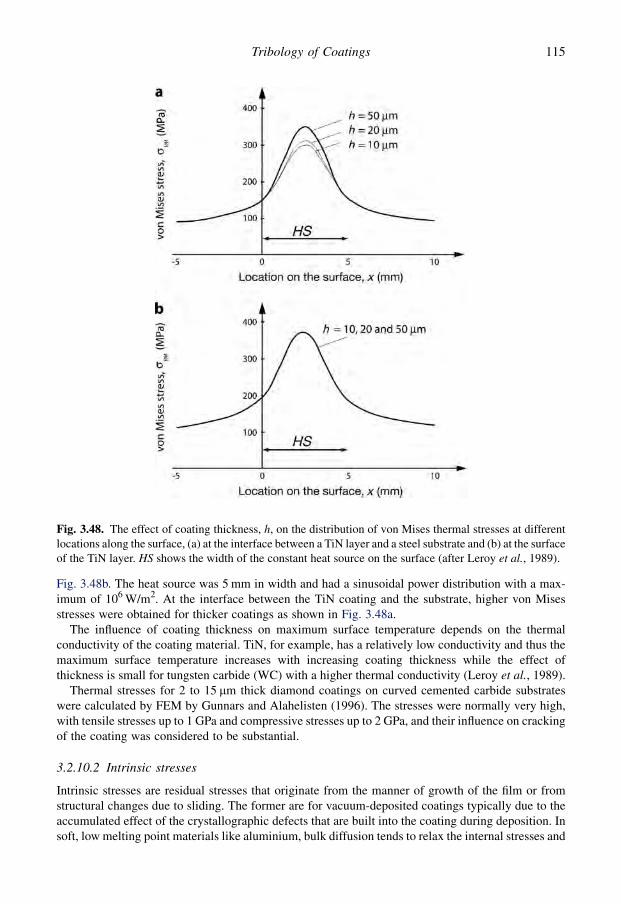
Fig. 3.48b. The heat source was 5 mm in width and had a sinusoidal power distribution with a max-imum of 106 W/m2. At the interface between the TiN coating and the substrate, higher von Misesstresses were obtained for thicker coatings as shown in Fig. 3.48a.
The influence of coating thickness on maximum surface temperature depends on the thermalconductivity of the coating material. TiN, for example, has a relatively low conductivity and thus themaximum surface temperature increases with increasing coating thickness while the effect ofthickness is small for tungsten carbide (WC) with a higher thermal conductivity (Leroy et al., 1989).
Thermal stresses for 2 to 15 mm thick diamond coatings on curved cemented carbide substrateswere calculated by FEM by Gunnars and Alahelisten (1996). The stresses were normally very high,with tensile stresses up to 1 GPa and compressive stresses up to 2 GPa, and their influence on crackingof the coating was considered to be substantial.
3.2.10.2 Intrinsic stresses
Intrinsic stresses are residual stresses that originate from the manner of growth of the film or fromstructural changes due to sliding. The former are for vacuum-deposited coatings typically due to theaccumulated effect of the crystallographic defects that are built into the coating during deposition. Insoft, low melting point materials like aluminium, bulk diffusion tends to relax the internal stresses and
Fig. 3.48. The effect of coating thickness, h, on the distribution of von Mises thermal stresses at differentlocations along the surface, (a) at the interface between a TiN layer and a steel substrate and (b) at the surfaceof the TiN layer. HS shows the width of the constant heat source on the surface (after Leroy et al., 1989).
115Tribology of Coatings

to prevent their accumulation. However, the diffusion processes can also cause defects to form. Inhard, high melting point materials like chromium deposited at low temperatures, intrinsic stressesaccumulate and tend to dominate thermal stresses. Stress cracking and buckling are commonlyobserved (Thornton and Hoffman, 1989; Thompson and Carel, 1996; Cammarata, 2004; Musil, 2004;Pauleau, 2008).
The growth-originated stresses are similar to the intrinsic stresses that are formed in the bulkmaterial during cold working, with strains associated with various lattice defects created by thedeformation. The density of defects that are formed in the film during deposition can be two orders ofmagnitude higher than those produced by the severest cold-work treatment of a bulk material. Theintrinsic stresses can be in the range of 0.1 to 3 GPa and are therefore comparable to the yield strengthof most materials (Thornton and Hoffman, 1989).
The intrinsic stresses in hard PVD coatings are generally compressive and strongly dependent onthe process parameters, especially on the energy of ion bombardment on the growing film. Thecreation of internal stress has been explained by Knotek et al. (1991) by a phenomenological modeldescribing the interaction of bombarding ions from the plasma and coating ions, whose mobility isrestricted by their position on the substrate or previously deposited layers in the coating. Ions oratoms of the vaporized or sputtered material will occupy sites that would normally be too small forthem, due to their high kinetic energy or as a result of impacting with other high-velocity particles(Fig. 2.9).
The intrinsic stresses in vacuum-deposited coatings are related to the microstructure and thussensitive to the deposition conditions. A schematic representation of the dependence of micro-structure in sputtered coatings on the pressure of the argon working gas and the substrate temperatureand coating material melting point temperature ratio is shown in Fig. 2.7. Coatings in the zone T(transition) region have a dense fibrous structure with a smooth, highly reflective surface. Largeintrinsic stresses can form in this region. Coatings in the zone 1 region are characterized bya structure consisting of tapered crystals separated by open, voided boundaries. The structure is tooporous to support stresses and has a rough, poorly reflective surface. The zone 2 structure consists ofcolumnar grains separated by distinct, intercrystalline boundaries. Recovery limits the intrinsicstresses. Zone 3 is characterized by a range of conditions where bulk diffusion has a dominant in-fluence on the final structure of the coating. Recrystallization occurs if sufficient strain is built intothe coating during deposition. Recovery and recrystallization limit the intrinsic stresses (Thorntonand Hoffman, 1989).
For hard TiN coatings in the thickness range of 4.6 to 28 mm, which exhibit compressive stresses,Kennedy and Tang (1990) found that the residual stresses were beneficial to the stability of coatingsbecause the tensile stresses that occurred in the coatings during sliding were reduced. The tendencyfor spalling and delamination of coatings tends to increase with increased coating thickness as stressesbuild up.
For even harder CVD diamond films deposited on polycrystalline tungsten substrates Guo andAlam (1991) found that the residual strain in the film was non-uniform and tensile in nature. Themagnitude of strain increased with substrate temperature and was less than the thermal mismatchbetween diamond and tungsten between room and deposition temperature.
The modulus of elasticity influences the direction of crack propagation in coated surfaces withresidual stresses. This was shown by Drory et al. (1988) in an analytical and experimental study. Forfilms having a moderately high Young’s modulus, cracks close to the interface divert into the sub-strate; this was observed, for example, for chromium films on silicon and on silicon oxide. For lowYoung’s modulus films, such as polymers, brittle substrate cracks tend to be attracted toward theinterface and the film cohesion is more likely to be affected by the interface. When the substrate isrelatively tough, such as a metal, the crack would be constrained to propagate along the interface or inthe film close to the interface, and decohesion is determined by a mixed mode fracture resistance ofthe interfacial zone. Drory et al. (1988) also showed that the existence of an asymptotic limit for plane
116 Coatings Tribology

cracks allows the definition of a critical film thickness, below which complete decohesion of films isinhibited.
3.2.11 Influence of interface cracks
Fracture near the surface often starts from imperfections in the material that form the nucleus forfracture initiation and propagation. Common imperfections are broken bonds on the interfaces, andvoids, inclusions and dislocations in the layer. These imperfections have a disturbing effect on thestress field and the strains generated in the material.
Analytical solutions for coated surfaces with a flaw or a crack have been developed by a number ofauthors starting from Erdogan and Gupta (1971a, b) and reviewed by Hills et al. (1990). Many of thesolutions are limited in use, because of the small number of cracks analysed, usually only one, andassumptions on the location of displacement zones along the crack faces.
An attempt to solve the problem of a spall more typical to those observed experimentally has beenpresented by Breton and Dubourg (1991a, b). Using a half analytical and half numerical model basedon the dislocation theory they simultaneously analysed the combination of an interfacial crack thatpropagates at the interface and a surface breaking crack that propagates normally to the interface. Theenergy release rate was determined at the crack tips. With the model they could show that the crackinteraction favours propagation and that the surface breaking crack propagates down to the interfaceand the interfacial crack propagates at the interface in a direction opposite to that of the loaddisplacement.
A theoretical model for multiple fatigue cracks situated close to a loading zone has been developedby Dubourg and Villechaise (1992) and Dubourg et al. (1992). They considered straight arbitrarilyoriented cracks and tested the method for up to five cracks without any indication of a limitation incrack number. For the analysis they identified five interaction mechanisms which depend on thedistance between cracks, their relative position with respect to the loading zone, the interfacial crackcoefficient of friction, and loading mode conditions: i.e. the step effect, the plug effect, the tilt effect,the stretch effect and the stretch–tilt effect as shown in Fig. 3.49.
The surface cracking in a multilayer coated surface containing a crack perpendicular to the surfacedue to repeated sliding of a rigid counterbody was analysed using linear elastic fracture mechanicsand finite element method by Gong and Komvopoulos (2004b). They conclude that the surfacecracking is controlled by the tensile fracture mode, longer cracks produce significantly higher stressintensity factor, KI, values, higher friction increases significantly both KI and KII due to the strongeffect of surface shear traction on the crack tip stresses and an increase in friction at the crack in-terface promotes stress relaxation. The initial crack growth was found to occur at an angle of about10� from the original crack plane, independent of the initial crack length. At the first few crackgrowth increments the crack growth paths exhibited a common deviation from the original crackplane by about 57�.
3.3 Surface Fracture and Wear Products
Load-induced deformations of a coated surface generate surface stresses that may be high enough toresult in surface fracture. Fracture is the separation of a body into two or more pieces in response to animposed stress. The wear process is related to fracture since material is separated from the surface.Wear always starts with breaking of cohesive or adhesive material bonds. This is called surfacecracking when it is observed on a macro- or microlevel. However, the crack starts with the breaking ofatomic bonds and material separation taking place already on a molecular level. Cracking and
117Tribology of Coatings
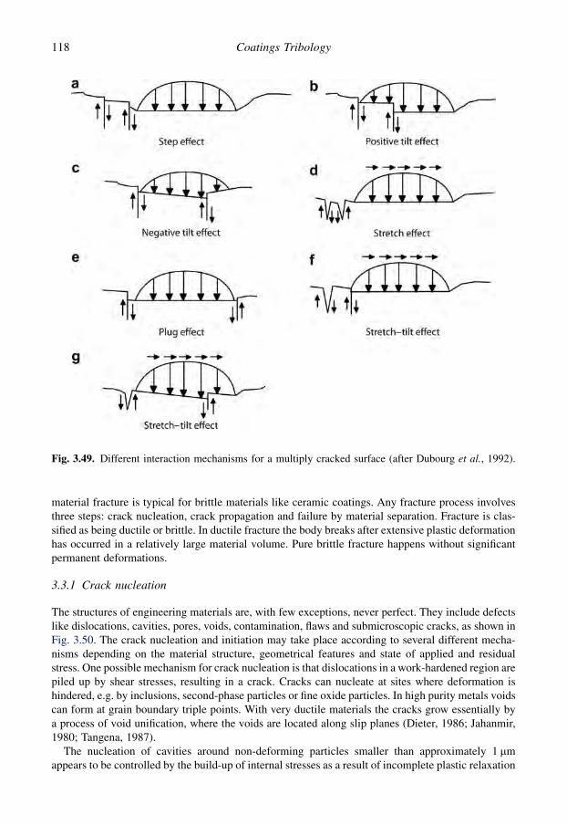
material fracture is typical for brittle materials like ceramic coatings. Any fracture process involvesthree steps: crack nucleation, crack propagation and failure by material separation. Fracture is clas-sified as being ductile or brittle. In ductile fracture the body breaks after extensive plastic deformationhas occurred in a relatively large material volume. Pure brittle fracture happens without significantpermanent deformations.
3.3.1 Crack nucleation
The structures of engineering materials are, with few exceptions, never perfect. They include defectslike dislocations, cavities, pores, voids, contamination, flaws and submicroscopic cracks, as shown inFig. 3.50. The crack nucleation and initiation may take place according to several different mecha-nisms depending on the material structure, geometrical features and state of applied and residualstress. One possible mechanism for crack nucleation is that dislocations in a work-hardened region arepiled up by shear stresses, resulting in a crack. Cracks can nucleate at sites where deformation ishindered, e.g. by inclusions, second-phase particles or fine oxide particles. In high purity metals voidscan form at grain boundary triple points. With very ductile materials the cracks grow essentially bya process of void unification, where the voids are located along slip planes (Dieter, 1986; Jahanmir,1980; Tangena, 1987).
The nucleation of cavities around non-deforming particles smaller than approximately 1 mmappears to be controlled by the build-up of internal stresses as a result of incomplete plastic relaxation
Fig. 3.49. Different interaction mechanisms for a multiply cracked surface (after Dubourg et al., 1992).
118 Coatings Tribology

due to local dislocation storage and hence local work hardening around the particles (Goods andBrown, 1979). In ceramic surface coatings with a columnar structure the crack nucleation is expectedto take place between the columnar grains.
Based on macroscale experimental observations in rolling contact tests with bearing steel materials,Nelias et al. (1999) report that the cracks are either initiated from subsurface inclusions or surfacemicrocracks. They claim that the initiation and propagation of inclusion-initiated cracks is the mainmode of subsurface originated cracks in rolling bearings. Under the load a stress concentration is builtup around inhomogenities like inclusions and primary carbides. This is due to the elastoplasticmismatch between the inhomogenities and the martensitic matrix. Once the yield stress is reached,plastic strain is induced in a small volume surrounding the inclusion. Under repeated action thedislocations will move back and forth and accumulate. This process leads to localized changes in thesteel microstructure and a crack is nucleated in this domain once a critical density is reached.
Surface microcracks are typically generated in the discontinuities of the surface topography such asat grinding marks or short wavelength surface roughness in operating conditions like rolling contactfatigue (Nelias et al., 1999). The process of initiation of surface microcracks and formation ofmicrospalls along grinding marks is shown schematically in Fig. 3.51a. Microcracks may alsopropagate parallel to the surface at a few micrometres depth along the machining direction, leading tothe formation of microspalls as shown in Fig. 3.51c. These processes have mainly been observed inpure rolling. Sliding may play a significant role, as it produces transverse microcracks at an angle of30 to 40� to the direction of the friction force. The cracks are located mainly on the top of largeroughness peaks as shown in Fig. 3.51b. There are indications that the local friction coefficient at thetop of asperities may be large enough to initiate transverse microcracks. Such microcracks are at theorigin of microspalls, usually wider and deeper than those observed under pure rolling conditions.Depending on the combination of load movement, friction direction and crack orientation a lubricantmay help to propagate surface cracks by hydraulic pressure effects.
The crack nucleation conditions in partial slip fretting wear contact conditions has been analysedby Fouvry et al. (2004a) and they found only a very minor effect of normal force on the nucleationcondition. The crack nucleation started at a constant threshold value of the tangential force.
3.3.2 Surface crack propagation
The modern fracture mechanics approach is based on linear elastic fracture mechanics (LEFM)and is widely used to explain the process of crack propagation and to predict crack growth(Anderson, 1995; Shukla, 2005) typically for systems with cracks longer than about 1 mm. However,
Fig. 3.50. The initial stage of the process of wear particle formation by shear deformation of voids in thematerial near the surface (after Suh, 1973).
119Tribology of Coatings
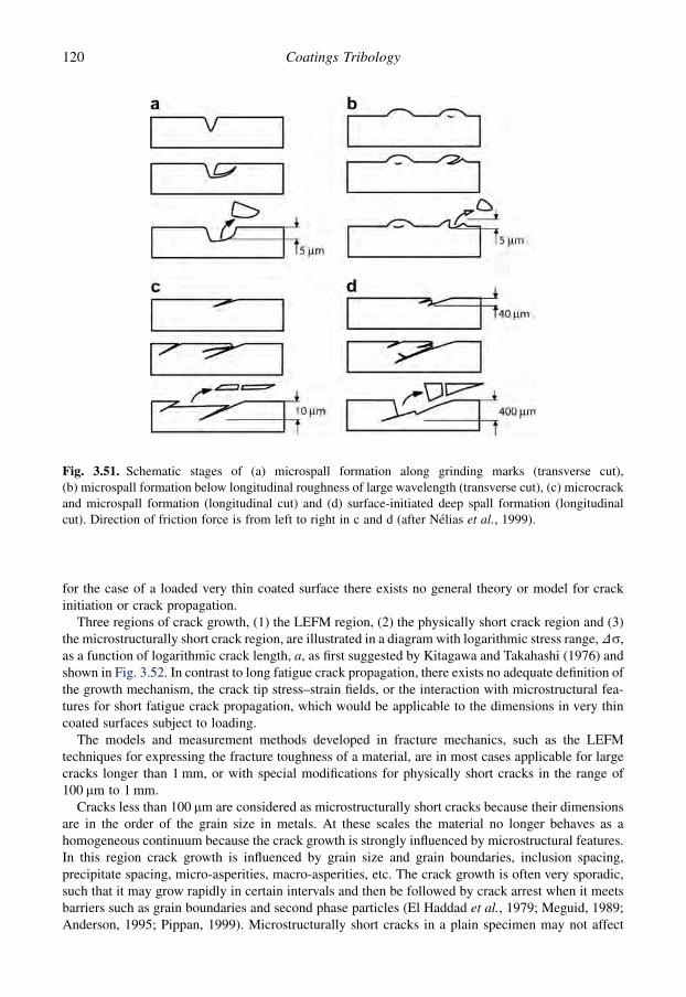
for the case of a loaded very thin coated surface there exists no general theory or model for crackinitiation or crack propagation.
Three regions of crack growth, (1) the LEFM region, (2) the physically short crack region and (3)the microstructurally short crack region, are illustrated in a diagram with logarithmic stress range, Ds,as a function of logarithmic crack length, a, as first suggested by Kitagawa and Takahashi (1976) andshown in Fig. 3.52. In contrast to long fatigue crack propagation, there exists no adequate definition ofthe growth mechanism, the crack tip stress–strain fields, or the interaction with microstructural fea-tures for short fatigue crack propagation, which would be applicable to the dimensions in very thincoated surfaces subject to loading.
The models and measurement methods developed in fracture mechanics, such as the LEFMtechniques for expressing the fracture toughness of a material, are in most cases applicable for largecracks longer than 1 mm, or with special modifications for physically short cracks in the range of100 mm to 1 mm.
Cracks less than 100 mm are considered as microstructurally short cracks because their dimensionsare in the order of the grain size in metals. At these scales the material no longer behaves as ahomogeneous continuum because the crack growth is strongly influenced by microstructural features.In this region crack growth is influenced by grain size and grain boundaries, inclusion spacing,precipitate spacing, micro-asperities, macro-asperities, etc. The crack growth is often very sporadic,such that it may grow rapidly in certain intervals and then be followed by crack arrest when it meetsbarriers such as grain boundaries and second phase particles (El Haddad et al., 1979; Meguid, 1989;Anderson, 1995; Pippan, 1999). Microstructurally short cracks in a plain specimen may not affect
Fig. 3.51. Schematic stages of (a) microspall formation along grinding marks (transverse cut),(b) microspall formation below longitudinal roughness of large wavelength (transverse cut), (c) microcrackand microspall formation (longitudinal cut) and (d) surface-initiated deep spall formation (longitudinalcut). Direction of friction force is from left to right in c and d (after Nelias et al., 1999).
120 Coatings Tribology
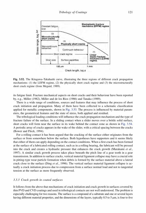
its fatigue limit. Fracture mechanical aspects on short cracks and their behaviour have been reportedby, e.g., Miller (1982), Miller and de los Rios (1986) and Tanaka (1989).
There is a wide range of conditions, sources and features that may influence the process of shortcrack initiation and propagation. Many of them have been collected to a schematic classificationapplied for metallic components, shown in Fig. 3.53. The process is influenced by material param-eters, the geometrical features and the state of stress, both applied and residual.
The tribological loading conditions will influence the crack propagation mechanism and the type offracture failure of the surface. In a sliding contact when a slider moves over a brittle solid surface,short cracks will form near the surface in its wake behind the contact zone as shown in Fig. 3.54.A periodic array of cracks appears in the wake of the slider, with a critical spacing between the cracks(Bower and Fleck, 1994).
For a rolling contact it has been argued that the cracking of the surface either originates from thesurface or from somewhere below the surface. Both hypotheses have supporters and it seems likelythat either of them can apply depending on the contact conditions. When a first crack has been formedat the surface of a lubricated rolling contact, such as in a rolling bearing, the lubricant will be pressedinto the crack and creates a hydraulic pressure that enhances the crack growth (Murakami et al.,1997). A similar crack growth process takes place beneath the pitch line of a gear tooth in a geartransmission. In addition to surface cracks, vertical material ligament collapse may have a crucial rolein pitting-type wear particle formation when debris is formed by the surface material above a lateralcrack close to the surface (Ding et al., 1996). The vertical surface material ligament collapse is ac-tually a crack initiation process due to compression from a surface normal load and not to tangentialtension at the surface as more frequently observed.
3.3.3 Crack growth in coated surfaces
It follows from the above that mechanisms of crack initiation and crack growth in surfaces covered bythin PVD and CVD coatings and used in tribological contacts are not well understood. The problem isespecially challenging for two reasons. The surface is a compound of a substrate and one or several layershaving different material properties, and the dimensions of the layers, typically 0.5 to 5 mm, is four to five
Fig. 3.52. The Kitagawa–Takahashi curve, illustrating the three regions of different crack propagationmechanisms: (1) the LEFM regime, (2) the physically short crack regime and (3) the microstructurallyshort crack regime (from Meguid, 1989).
121Tribology of Coatings

orders of magnitude smaller than the size range of the well-established linear elastic fracture mechanicsconcepts. Actually, the dimension of the coating overlaps the size range, 0.1–1 mm, where materialscientists normally define crack nucleation and initiation to take place (Miller, 1982).
There are some special features in the cracking of a surface covered by a thin coating. As a crack isinitiated in a thin coating it normally goes all the way down to the coating/substrate interface. It maybe only one single crack but often a whole system of cracks is generated. When reaching the interfacethe crack may change direction and propagate along the coating/substrate interface or it may penetratedeeper down into the substrate (y-direction in Fig. 3.55). The crack growth in the lateral direction(z-direction in Fig. 3.55) is important since it influences the conditions for coating delamination.
Fig. 3.53. Classification of different sources and features for short crack initiation and propagation inmetallic components (from Meguid, 1989).
122 Coatings Tribology

Analytical and numerical solutions of fully and partially cracked thin coatings in a stress field intension and unstressed have been presented by Beuth (1992), Mencik (1996) and Oliveira and Bower(1996). Still, the use of these solutions in practical applications is not easy and straightforward due tothe mathematical complexity.
Surface cracking of a multilayered surface due to repeated sliding of a rigid asperity was analysedby linear elastic fracture mechanics and the finite element method by Gong and Komvopoulos (2004b,2005). They studied the propagation of a partial perpendicular crack in the first coating layer and cameup with several very interesting conclusions. The significantly higher values, by an order of magni-tude, of the tensile stress intensity factor, KI, than those of the shear intensity factor, KII, indicate thatsurface cracking in a multilayered surface due to sliding is controlled by the tensile fracture mode.Longer surface cracks produce significantly higher KI values while higher friction increases both KI
and KII significantly due to the strong effect of the surface shear traction on the crack-tip stresses. Theincrease of friction at the crack interface promotes stress relaxation but the effect on KI is negligible.The initial crack growth was found to occur at an angle of ~10� from the original crack plane, in-dependent of the initial crack length (see propagating crack in Fig. 3.54). After the first one to threecrack growth increments, the crack growth paths are almost parallel to each other, exhibitinga common deviation from the original crack by ~57� and this was reported to be in fair agreement withexperimental observations.
Fig. 3.54. A propagating crack is formed in the wake behind a slider moving over a brittle flat surface.
Fig. 3.55. Crack propagation in a thin coating loaded by stress field in tension.
123Tribology of Coatings
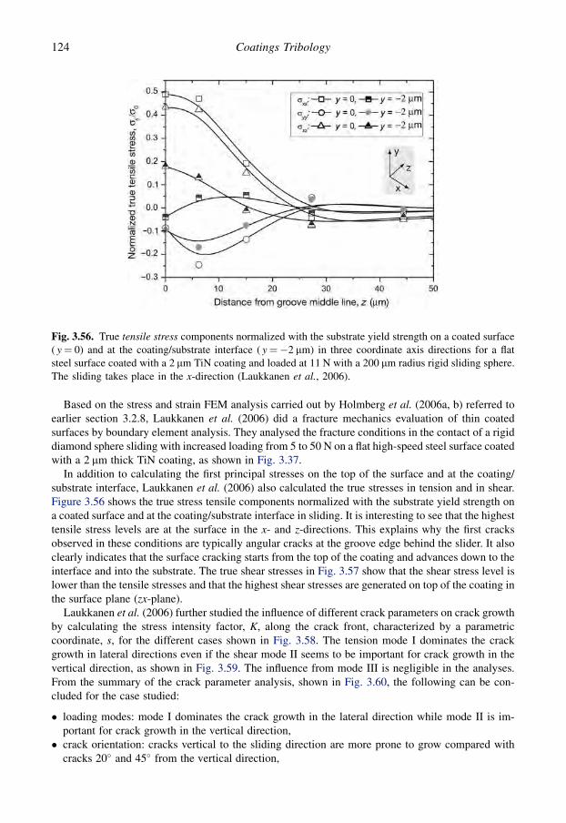
Based on the stress and strain FEM analysis carried out by Holmberg et al. (2006a, b) referred toearlier section 3.2.8, Laukkanen et al. (2006) did a fracture mechanics evaluation of thin coatedsurfaces by boundary element analysis. They analysed the fracture conditions in the contact of a rigiddiamond sphere sliding with increased loading from 5 to 50 N on a flat high-speed steel surface coatedwith a 2 mm thick TiN coating, as shown in Fig. 3.37.
In addition to calculating the first principal stresses on the top of the surface and at the coating/substrate interface, Laukkanen et al. (2006) also calculated the true stresses in tension and in shear.Figure 3.56 shows the true stress tensile components normalized with the substrate yield strength ona coated surface and at the coating/substrate interface in sliding. It is interesting to see that the highesttensile stress levels are at the surface in the x- and z-directions. This explains why the first cracksobserved in these conditions are typically angular cracks at the groove edge behind the slider. It alsoclearly indicates that the surface cracking starts from the top of the coating and advances down to theinterface and into the substrate. The true shear stresses in Fig. 3.57 show that the shear stress level islower than the tensile stresses and that the highest shear stresses are generated on top of the coating inthe surface plane (zx-plane).
Laukkanen et al. (2006) further studied the influence of different crack parameters on crack growthby calculating the stress intensity factor, K, along the crack front, characterized by a parametriccoordinate, s, for the different cases shown in Fig. 3.58. The tension mode I dominates the crackgrowth in lateral directions even if the shear mode II seems to be important for crack growth in thevertical direction, as shown in Fig. 3.59. The influence from mode III is negligible in the analyses.From the summary of the crack parameter analysis, shown in Fig. 3.60, the following can be con-cluded for the case studied:
� loading modes: mode I dominates the crack growth in the lateral direction while mode II is im-portant for crack growth in the vertical direction,� crack orientation: cracks vertical to the sliding direction are more prone to grow compared with
cracks 20� and 45� from the vertical direction,
Fig. 3.56. True tensile stress components normalized with the substrate yield strength on a coated surface( y¼ 0) and at the coating/substrate interface ( y¼�2 mm) in three coordinate axis directions for a flatsteel surface coated with a 2 mm TiN coating and loaded at 11 N with a 200 mm radius rigid sliding sphere.The sliding takes place in the x-direction (Laukkanen et al., 2006).
124 Coatings Tribology

� crack density: cracks with a larger crack spacing in the regular crack field, here 30 mm, are moreprone to grow compared to smaller spacing, 5 or 10 mm, or single cracks,
� location in crack field: the centre crack in a crack field is more prone to grow compared to edgecrack or other cracks in the field,� location in crack groove: transverse cracks in the middle of the groove are more prone to grow
compared to both transverse and angular side cracks at the groove edge, and� tensile load biaxiality: has a marginal influence on crack growth.
Fig. 3.57. True shear stress components normalized with the substrate yield strength on a coated surface( y¼ 0) and at the coating/substrate interface ( y¼�2 mm) in three coordinate planes for a flat steel surfacecoated with a 2 mm TiN coating. The sliding takes place in the x-direction (Laukkanen et al., 2006).
Fig. 3.58. Crack growth parameters.
125Tribology of Coatings

In ceramic coatings the thickness and the grain size are important parameters for crack prop-agation. In indentation tests of 1 to 10 mm thick Al2O3 coatings on cemented carbide substrates Yuanand Hayashi (1999) found that the critical load for generation of radial cracks decreased with in-creasing coating thickness and that the grain size of the coatings decreased with the thickness. Acoarser grained microstructure generally displays a lower cohesive strength as compared with a fine
Fig. 3.59. Crack growth stress intensity factor normalized with K value at the deepest point of single crackcase under uniaxial tension for the three fracture modes along the normalized crack front defined inFig. 3.58 for a flat steel surface coated with a 2 mm TiN coating (Laukkanen et al., 2006).
Fig. 3.60. Summary of the effect of different crack parameters on normalized stress intensity factor fora flat steel surface coated with a 2 mm TiN coating and loaded at 11 N with a 200 mm radius rigid slidingsphere (Laukkanen et al., 2006).
126 Coatings Tribology

grained microstructure. Thus the fracture strength of the coating increases with decreasing grain sizeand decreasing thickness.
Nanocrystalline-amorphous TiC-amorphous carbon (a-C) composite coatings have been producedby Voevodin and Zabinsky (1998a, b) with a combination of high hardness and toughness. In theircoating design, nanocrystals of 10 to 50 nm size were encapsulated in an amorphous phase, sepa-rating the nanocrystals at a distance of 5 nm from each other. This permitted the generation ofdislocations and grain boundary microcracks and nanocracks, which terminated in the surroundingamorphous matrix. This surface design achieved a self-adjustment in composite deformation fromelastic to plastic at loads exceeding the elastic limit, as opposed to deformation from elastic to brittlefracture.
For amorphous diamond-like carbon (DLC) coatings in the thickness range of 0.7 to 2 mm it hasbeen shown that the hardness and apparent fracture toughness of the coating/substrate combination,measured by Vickers indentation, depend on the thickness of the coating (Kodali et al., 1997). Thehardness and the apparent fracture toughness of the coating, both of which influence the wear, in-creased with increasing coating thickness. The hardness and the thickness influenced the initiation ofcracks, whereas the residual stress in the film influenced the propagation of cracks.
In a study of very thin DLC coatings in the thickness range of 3.5 to 20 nm, Sundarajan andBhushan (1999) conclude that the formation of cracks depends on the hardness and fracturetoughness of the coating. They suggest that the observed non-uniform failure depends on variationsin the coating properties at different locations in the material volume. Surface cracks are developedin weaker regions with lower fracture toughness. As cracks propagate they are forced to expandwithin the weak region, as the neighbouring strong regions inhibit extensive lateral crack growth.Because of this, cracks propagate down to the interface, where, aided by the interfacial stresses, theyget diverted along the interface just enough to cause local delamination of the coating. Simulta-neously, the weakened regions experience excessive ploughing. Thus weaker regions fail whilestronger regions remain wear resistant. The propagation of cracks along the coating/substrate in-terface is suppressed due to the strong adhesion of the coatings, otherwise coating delaminationwould take place.
3.3.4 Toughness and fracture toughness in coated surfaces
There is no widely established way of expressing the resistance to fracture of a coated surface.However, the study of toughness and fracture toughness for thin coatings and coated surfaces isreceiving wider support and this is certainly recommended, since they are well-defined and widelyused parameters for the crack growth resistance of bulk materials. In the literature there are severalother expressions used for the property of a coated surface to resist fracture, such as cracking re-sistance, higher/lower critical load, etc. The drawbacks of these are that they are related to somecertain experimental device and lack generality.
Not to confuse the classical concept of fracture toughness it should be remembered that fracturetoughness describes the strain energy release rate in the growth of a pre-existing crack, whereastoughness describes the total energy input required to cause the material to fail, i.e. both to create thecrack and to enable the crack to grow.
When using the expression of fracture toughness of a coated surface it is important to note thedistinction between the fracture toughness of the coating and that of the coated surface. Most methodsto estimate the fracture toughness of a coated surface relate the KC value to the coating–substratesystem and not purely to the coating. This may not be a drawback since normally it is the fracturetoughness of the coated surface, the system that is really of interest and should be optimized fora certain purpose.
The most common ways to estimate the fracture toughness of a coated surface are first to empir-ically deform the surface by indentation, bending, buckling, scratching or tensile testing and then
127Tribology of Coatings

calculate the KC value analytically or based on finite element analysis (Zhang et al., 2005a). Somevalues of the fracture toughness of coated surfaces are presented in Table 3.7. Most authors havecalculated the fracture toughness related to cracks going vertically through the coating, KC, butinterestingly Diao et al. (1994b) and Blug et al. (2001) have also estimated the interface fracturetoughness, KC, int, which is the adhesion-related resistance to crack propagation along the coating/substrate interface.
The four-point bending test has been used to rank the cracking resistance of different PVD coatings.Wiklund et al. (1997a) found a significantly higher cracking resistance for their PVD deposited2.5 mm thick CrN coatings on a hardened HSS substrate compared to 4.3 mm thick TiN coatings on thesame substrate. Zoestbergen and De Hosson (2002) found a higher cracking resistance for PVD-deposited TiN coatings compared to TiN/TiAlN multilayer coatings and the lowest cracking re-sistance for Ti(C,N) coatings all deposited on AISI tool steel substrates and with coating thicknessesof 2.5 to 4.4 mm. Very interestingly they also report that they found no measurable influence of surfaceroughness on crack density in the roughness range of Ra¼ 0.01 to 1.0 mm for the TiN coatedspecimen.
3.3.5 Crack patterns
Continuous loading of a surface coated with a thin brittle coating results in a first crack, then crackgrowth, new cracks, growth of the new cracks and crack merging according to a pattern that is specificfor the loading conditions and the surfaces in interaction. Different typical crack patterns are oftenproduced by the scratch test where a spherical stylus is sliding with increasing load over a coatedsurface. Figure 3.61 shows how first angular cracks are formed at the groove edge behind the slidingsphere (a), some time later at higher loading they are accompanied by parallel cracks along the grooveedge (b) and the angular cracks are growing and merging to transverse semicircular cracks (c). A newstage is reached at higher loading when the first coating plates are spalled off due to adhesion failure(e) and finally large areas of the coating are spalled off resulting in coating breakthrough (f). Thestress conditions resulting in this process have been analysed by Holmberg et al. (2003) and aredescribed in section 3.2.8.
The fracture behaviour is different depending on whether the coating is hard or soft, ductile orbrittle or elastic and whether the substrate is hard or soft in relation to the coating. Five such caseswhere the coating and substrate deformations are shown and the cracking is indicated both for well-adhered and poorly adhered coatings are shown in Fig. 3.62. A soft or elastic substrate results in largerdeformation of the coating. If the coating is brittle it cannot deform accordingly and will crack. Thecoating thickness also influences the toughness of the coating.
The loading of a coated surface results in deformation and failure both in front of the slidingcontact and behind it. Spalling and buckling typically take place in front of the slider as a result ofthe compressive stress field preceding the moving slider and the cracks formed are concentric withthe front part of the sphere. Spalling is a result of total detachment of the coating from the substrateand flaking off. Conformal and tensile cracking takes place when the coating remains fully ad-herent. The conformal cracking takes place in front of the slider. Tensile cracking takes placebehind the slider and the cracks are formed concentric with the trailing part of the sphere, as shownin Fig. 3.63. Some of the cracking failures taking place in front of the slider may go througha change in shape as they are ridden over and possibly embedded by the sliding sphere and theirappearance in the groove bottom may be quite different from the original failure shape (Burnett andRickerby, 1987b).
The crack pattern in a scratch test has been studied and classified by Bull (1991, 1997). He showsfive different crack patterns for brittle failure modes: tensile cracking, Hertz cracking, recoveryspalling, compressive spalling and gross spalling. In ductile failure he identifies four modes: tensilecracking, conformal cracking, buckling and spalling. Somewhat surprisingly it has been experimentally
128 Coatings Tribology

Table 3.7. Some values for fracture toughness of coated surfaces from literature.
Coating/substrate Depositionprocess
Coatingthickness (mm)
Empiricassessment
Fracturetoughness, KC
(MPa $ m�2)
Reference
TiN/cemented carbide CVD 1.5–11.5 Indentation 2.7 (KIC,int¼ 0.08) Diao et al. (1994b)TiN/steel S6-5-2 PACVD 4.8 Bendingþ pc 8.7 Jaeger et al. (2000)TiN/high-speed steel PVD 2 Scratch test 4–7 Holmberg et al. (2003) and
Laukkanen et al. (2006)TiCN/steel S6-5-2 PACVD 4.5 Bendingþ pc 7.9 Jaeger et al. (2000)TiAlN/steel S6-5-2 PACVD 7.9 Bendingþ pc 3.8 Jaeger et al. (2000)TiAlSiN/WC–Co PVD 2 Indentation 1.55–2.1 Nakonechna et al. (2004)Al2O3/cemented carbide CVD 1.7–12.5 Indentation 2.2 (KIC,int¼ 0.05) Diao et al. (1994b)Al2O3/mild steel Plasma spray 200–300 Indentation 4.5 Xie and Hawthorne (1999)TiB2/cemented carbide Magnetron sputtering PVD 60 Vickers indentation 4.1 Berger (2002)DLC/silicon Sputtering 1.36–1.92 Indentation 1.14–1.57 Kodali et al. (1997)DLC (a-C)/silicon Cathodic arc PVD 0.4 Nano-indentation 10.9 Li et al. (1997); Li and Bhushan
(1998)DLC (a-C:H)/silicon Ion beam PVD 0.4 Nano-indentation 4.9–5.4 Li et al. (1997); Li and Bhushan
(1998)DLC/silicon PIIP PVD 1.27–1.92 Micro-indentation 10.1 Nastasi et al. (1999)DLC/steel 100Cr6 RF-PECVD 2 Indentation 1–2 (Gint¼ 0.55) Blug et al. (2001)W/steel Sputtering 2–16.4 Tensile test 1–2.5 Harry et al. (1998)W(C)/steel Sputtering 1.8–16 Tensile test 0.2–1 Harry et al. (1998)SiC/silicon APCVD 3 Indentation 0.78 Li et al. (1999)NiP/aluminium 9 Indentationþ pc 15 Tsui et al. (2001)Organic/inorganicfilm/float glass
Sol-gel 3–20 Indentation 0.07–0.26 Malzbender et al. (2000a)
KC,int¼ interfacial fracture toughness; Gint¼ interface toughness; pc¼ pre-cracked specimen
12
9T
ribo
log
yo
fC
oa
ting
s
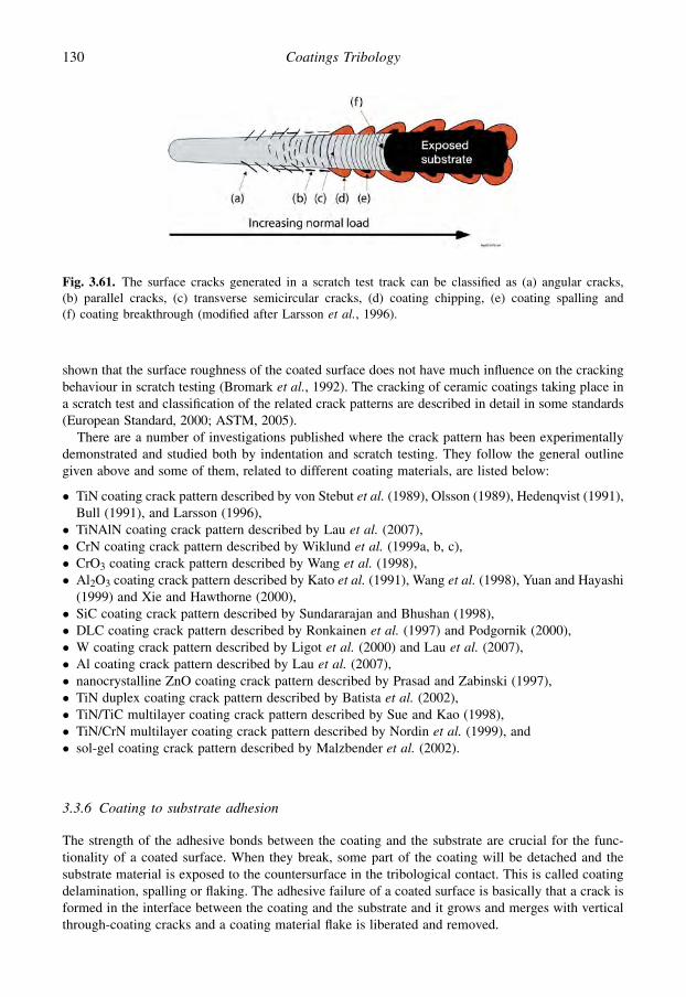
shown that the surface roughness of the coated surface does not have much influence on the crackingbehaviour in scratch testing (Bromark et al., 1992). The cracking of ceramic coatings taking place ina scratch test and classification of the related crack patterns are described in detail in some standards(European Standard, 2000; ASTM, 2005).
There are a number of investigations published where the crack pattern has been experimentallydemonstrated and studied both by indentation and scratch testing. They follow the general outlinegiven above and some of them, related to different coating materials, are listed below:
� TiN coating crack pattern described by von Stebut et al. (1989), Olsson (1989), Hedenqvist (1991),Bull (1991), and Larsson (1996),� TiNAlN coating crack pattern described by Lau et al. (2007),� CrN coating crack pattern described by Wiklund et al. (1999a, b, c),� CrO3 coating crack pattern described by Wang et al. (1998),� Al2O3 coating crack pattern described by Kato et al. (1991), Wang et al. (1998), Yuan and Hayashi
(1999) and Xie and Hawthorne (2000),� SiC coating crack pattern described by Sundararajan and Bhushan (1998),� DLC coating crack pattern described by Ronkainen et al. (1997) and Podgornik (2000),� W coating crack pattern described by Ligot et al. (2000) and Lau et al. (2007),� Al coating crack pattern described by Lau et al. (2007),� nanocrystalline ZnO coating crack pattern described by Prasad and Zabinski (1997),� TiN duplex coating crack pattern described by Batista et al. (2002),� TiN/TiC multilayer coating crack pattern described by Sue and Kao (1998),� TiN/CrN multilayer coating crack pattern described by Nordin et al. (1999), and� sol-gel coating crack pattern described by Malzbender et al. (2002).
3.3.6 Coating to substrate adhesion
The strength of the adhesive bonds between the coating and the substrate are crucial for the func-tionality of a coated surface. When they break, some part of the coating will be detached and thesubstrate material is exposed to the countersurface in the tribological contact. This is called coatingdelamination, spalling or flaking. The adhesive failure of a coated surface is basically that a crack isformed in the interface between the coating and the substrate and it grows and merges with verticalthrough-coating cracks and a coating material flake is liberated and removed.
Fig. 3.61. The surface cracks generated in a scratch test track can be classified as (a) angular cracks,(b) parallel cracks, (c) transverse semicircular cracks, (d) coating chipping, (e) coating spalling and(f) coating breakthrough (modified after Larsson et al., 1996).
130 Coatings Tribology

Adhesion is defined as the molecular attraction between bodies in contact. According to thefracture mechanics approach the adhesion energy or interfacial fracture energy of a coating–substrate system is the energy needed to propagate a crack along the interface between the coatingand the substrate by a unit area, denoted Gint. The growth of a crack along an interface can occurunder various loading modes, in particular the opening mode I, KI,int, and the shearing mode II, KII,int.The adhesion strength is the stress that the interface can withstand before fracturing. The resistanceto crack growth until fracture is called the interfacial fracture toughness, KC, int (see Table 3.7 insection 3.3.4).
The adhesion strength between the coating and the substrate is governed by various routes for crackpropagation depending on the elasticity, hardness and ductility of the coating and the substrate and thecoating thickness, and typically results in a spalling or a buckling failure (Swain and Mencik, 1994;Bull, 1997; Diao and Kandori, 2006). In practical systems it is not always clear if a failure at the
Fig. 3.62. Schematic cross-sections of various coating–substrate materials combinations and the influenceof interfacial adhesion on cracking in indentation (after Swain and Mencik, 1994).
131Tribology of Coatings

coating/substrate interface is a truly adhesive failure or a cohesive failure in the coating or in thesubstrate along and very close to the interface. So in reality cohesive failures at the subinterfacebetween the bulk material and the real interface to the coating are often referred to as adhesive failures(Malzbender et al., 2002). Even if the theoretical definition of adhesion is clear, the assessment of
Fig. 3.63. Schematic representation of some of the more common coating failure modes in the scratch testin profile and plan views: (a) spalling failure, (b) buckling failure, (c) chipping failure, (d) conformalcracking and (e) tensile cracking (after Burnett and Rickerby, 1987b).
132 Coatings Tribology
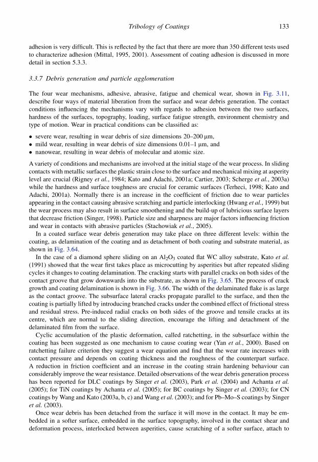
adhesion is very difficult. This is reflected by the fact that there are more than 350 different tests usedto characterize adhesion (Mittal, 1995, 2001). Assessment of coating adhesion is discussed in moredetail in section 5.3.3.
3.3.7 Debris generation and particle agglomeration
The four wear mechanisms, adhesive, abrasive, fatigue and chemical wear, shown in Fig. 3.11,describe four ways of material liberation from the surface and wear debris generation. The contactconditions influencing the mechanisms vary with regards to adhesion between the two surfaces,hardness of the surfaces, topography, loading, surface fatigue strength, environment chemistry andtype of motion. Wear in practical conditions can be classified as:
� severe wear, resulting in wear debris of size dimensions 20–200 mm,� mild wear, resulting in wear debris of size dimensions 0.01–1 mm, and� nanowear, resulting in wear debris of molecular and atomic size.
A variety of conditions and mechanisms are involved at the initial stage of the wear process. In slidingcontacts with metallic surfaces the plastic strain close to the surface and mechanical mixing at asperitylevel are crucial (Rigney et al., 1984; Kato and Adachi, 2001a; Cartier, 2003; Scherge et al., 2003a)while the hardness and surface toughness are crucial for ceramic surfaces (Terheci, 1998; Kato andAdachi, 2001a). Normally there is an increase in the coefficient of friction due to wear particlesappearing in the contact causing abrasive scratching and particle interlocking (Hwang et al., 1999) butthe wear process may also result in surface smoothening and the build-up of lubricious surface layersthat decrease friction (Singer, 1998). Particle size and sharpness are major factors influencing frictionand wear in contacts with abrasive particles (Stachowiak et al., 2005).
In a coated surface wear debris generation may take place on three different levels: within thecoating, as delamination of the coating and as detachment of both coating and substrate material, asshown in Fig. 3.64.
In the case of a diamond sphere sliding on an Al2O3 coated flat WC alloy substrate, Kato et al.(1991) showed that the wear first takes place as microcutting by asperities but after repeated slidingcycles it changes to coating delamination. The cracking starts with parallel cracks on both sides of thecontact groove that grow downwards into the substrate, as shown in Fig. 3.65. The process of crackgrowth and coating delamination is shown in Fig. 3.66. The width of the delaminated flake is as largeas the contact groove. The subsurface lateral cracks propagate parallel to the surface, and then thecoating is partially lifted by introducing branched cracks under the combined effect of frictional stressand residual stress. Pre-induced radial cracks on both sides of the groove and tensile cracks at itscentre, which are normal to the sliding direction, encourage the lifting and detachment of thedelaminated film from the surface.
Cyclic accumulation of the plastic deformation, called ratchetting, in the subsurface within thecoating has been suggested as one mechanism to cause coating wear (Yan et al., 2000). Based onratchetting failure criterion they suggest a wear equation and find that the wear rate increases withcontact pressure and depends on coating thickness and the roughness of the counterpart surface.A reduction in friction coefficient and an increase in the coating strain hardening behaviour canconsiderably improve the wear resistance. Detailed observations of the wear debris generation processhas been reported for DLC coatings by Singer et al. (2003), Park et al. (2004) and Achanta et al.(2005); for TiN coatings by Achanta et al. (2005); for BC coatings by Singer et al. (2003); for CNcoatings by Wang and Kato (2003a, b, c) and Wang et al. (2003); and for Pb–Mo–S coatings by Singeret al. (2003).
Once wear debris has been detached from the surface it will move in the contact. It may be em-bedded in a softer surface, embedded in the surface topography, involved in the contact shear anddeformation process, interlocked between asperities, cause scratching of a softer surface, attach to
133Tribology of Coatings

either of the surfaces, be involved in a tribochemical process to form a new compound or just beremoved from the contact zone. As the debris has just been detached from a solid it contains pureuncontaminated surfaces and may thus be chemically and physically active to form bonds with othersurfaces close to it. This is enhanced by the high local temperatures at the asperity level often involvedin sliding processes.
In these active contact conditions, often agglomeration of wear debris to larger material pieces isobserved (Rigney et al., 1984; Akagaki and Kato, 1987; Berthier, 2005). In sliding contacts withmaterials of different hardness (lead, zinc, aluminium, copper, nickel, titanium and steel), Hwanget al. (1999) observed different wear particle agglomeration behaviour depending on hardness andsliding direction. Smaller wear particles had a stronger tendency to join together and form larger ones.
Fig. 3.65. Schematic presentation of early cracks in sliding of a spherical diamond repeatedly on an Al2O3
coated flat WC alloy surface (after Kato et al., 1991).
Fig. 3.64. Three levels of wear debris generation in a coated surface: (a, b) flaking of coating materialfrom the top surface of the coating, (c, d) delamination or removal of coating pieces so that the substrate isexposed and (e, f) detachment of debris containing both coating and substrate material.
134 Coatings Tribology

Particles of soft and ductile metals had a stronger tendency to agglomerate than those of hard andbrittle metals. There was a difference in agglomeration behaviour depending on whether the slidingwas unidirectional or reciprocating and lower friction and wear was measured in the cases ofreciprocating sliding. Particle agglomeration was not just limited to one location but occurredsimultaneously over a distributed area and the observed particle or flake sizes were in the range of100–600 mm.
The mechanism of agglomeration is complicated due to adhesion and/or mechanical interlocking.The agglomerated particles can act as larger particles in the contact, detach to either of the surfaces orbe rejected from the contact (Yuan et al., 1999). Wear particle agglomeration has been reported insliding tests with DLC coated surfaces (Park et al., 2004; Wu et al., 2005), TiN coated surfaces(Achanta et al., 2005) and silver coated surfaces (Yang et al., 2001, 2003).
3.3.8 Transfer layers
It is common that wear particles attach to one of the contacting surfaces and continue to be active inthe tribological process in the form of a transfer layer. The formation of a transfer layer is the result ofa process that starts with surface deformation, then surface cracking, wear debris generation, oftenalso particle agglomeration and finally formation of a transfer layer, as shown in Fig. 3.67. Thematerial transfer layers generated in sliding coated contacts are generally some few micrometres inthickness but may vary in the range of 0.01 to 50 mm (Ko et al., 1992; Blomberg, 1993; Singer et al.,2003; Scharf and Singer, 2003c). Material between the two sliding surfaces in the form of debris orlayers is frequently called third bodies. Their rheological, flow and physiochemical behaviour in thetribological contact process has been analysed, described and modelled by Godet (1984), Descartesand Berthier (2001), Berthier (2005) and Fillot et al. (2007).
The material transfer mechanism is well known for polymers, e.g. polytetrafluoroethylene (PTFE),sliding on steel (see Fig. 4.3). Surface material from the polymer will wear off and attach by adhesionto the steel counterface to form an extensive PTFE film. This means that after some time of sliding, thetribological pair is actually PTFE sliding against a thin PTFE film on steel, which has very lowfriction. Similar mechanisms have been observed for sputtered, less than one micrometre thick, PTFEcoatings on steel substrates, resulting in film-like PTFE wear debris transfer to the steel counterface;and for sputtered polyimide (PI) coated steel, resulting in fine flake-like wear debris transfer to forma polymer layer on the steel counterface (Yamada et al., 1990). In rolling contact bearings in different
Fig. 3.66. Schematic presentation of crack growth and coating delamination in sliding of a sphericaldiamond repeatedly on an Al2O3 coated flat WC alloy surface (after Kato et al., 1991).
135Tribology of Coatings

gas environments PTFE films have transferred from the retainer onto CaF2 layers on the races andballs effectively protecting them from wear and increasing their endurance life (Nosaka et al., 1999).
Based on observations from sliding contacts with MoS2 and TiN coatings, Singer (1998) presentsa three-stage nanoscale model for the formation of reaction layers and for the build-up of transferlayers. First, a thin layer is removed from the coating and transferred to the counterface. Meanwhileboth the surface and the transfer layer can react with possible surrounding gases, forming newcompounds. The first films to be transferred to the countersurface may be very thin, only of moleculardimensions. As the transfer film thickens, it is extruded from the contact area and may break up toform new wear debris. This process is then repeated and a layer-by-layer build-up takes place. It hasbeen observed for MoS2 coatings that particle detachment appears to be preceded by deformation,reorientation and sometimes crack propagation within the first 20–50 nm of the coating.
One process of transfer layer formation is illustrated in Fig. 3.68, reported by Singer (1998) andSinger et al. (1996a, c). A metallic–ceramic tribocouple of Mo and SiC slides against each other ina reactive gas of O2 and initially the sliding seems to occur near the oxide–substrate interface(Fig. 3.68a) or at the interface between the transfer film and the track (Fig. 3.68b). Friction isdetermined by the shear strength of the interface. As debris builds up on the track the sliding occursbetween the transfer film and a debris-covered wear track with an interfacial chemistry different fromthe earlier surface (Fig. 3.68c). A low steady-state friction coefficient value of m¼ 0.01 was achievedfrom the tribochemical reaction products alone. However, without continuous exposure to gas, thefriction coefficient immediately rose to m¼ 1.
In a series of excellent detailed papers the group led by Singer has described the process of transferlayer formation and its influence on friction and wear for three low-friction coatings: 2 mm thick
Fig. 3.67. The process of surface layer formation starts with surface deformation and continues withsurface cracking, wear debris generation, particle agglomeration, transfer layer formation or reaction layerformation.
Fig. 3.68. A schematic presentation of detachment and transfer processes that produce transfer layers anddebris during sliding (after Singer et al., 1996c and Singer, 1998).
136 Coatings Tribology

diamond-like carbon coating, 0.3 mm thick amorphous Pb–Mo–S coating and annealed boron carbidecoating (Singer, 1998; Wahl et al., 1999; Dvorak et al., 2002; Scharf and Singer, 2003a, c; Singeret al., 2003). They report a number of very illustrative in situ optical microscopy video recordings,Raman, friction and wear measurements in reciprocating sliding contacts between a transparent glassor sapphire sphere and the coated surface. Even if transfer films originate from a parent material, theydo not always have the same phase or composition as the parent. With an amorphous Pb–Mo–Scoating the transfer film produced was MoS2, with a DLC coating the transfer film was a graphite-likecarbon layer, and with annealed BC the transfer film was either a mix of H3BH3 and carbon or, whenthe H3BH3 wore away, carbon alone. An increase in friction with Pb–Mo–S and DLC coatings wasobserved due to the changes in interfacial shear strength. The transfer films produced with the DLCcoatings were measured to be 100 to 200 nm thick. Similar transfer layer observations in slidingcontacts with DLC coated surfaces have been reported by Fontaine et al. (2004), Konca et al. (2005)and Wu et al. (2005).
A typical transfer film build-up process is described by Singer et al. (2003) with the Pb–Mo–Scoatings in the following way: as sliding began, a patchy transfer film attached to the contact area of thesphere; later, thicker, compact pads of debris formed at the leading/trailing edges of the contact; a fewdebris were also adhered to the coating; the relative motion between the sphere and the wear track onthe coating took place by interfacial sliding; as the humidity rose, some of the debris patches in thetransfer film began to extrude – moving at speeds of 3% of the sliding speed; loose debris were swept upfrom the track and collected at the leading/trailing edges of the contact, feeding additional debris intothe contact. The tribochemical process converts amorphous Pb–Mo–S into crystalline MoS2 and thetransformation occurs by creating basal-oriented layers at the outermost layers of the wear track.
A typical building-up process of a transferred surface layer in contacts with steel and hard coatingssuch as TiN, CrN and (TiAl)N has been described by Huang et al. (1994). As a result of the ploughingaction of hard coating asperities, slider material fragments were first removed and then adhered tosome preferential sites on the sliding track of the coating. The preferential sites were the highestasperities that made earliest contact with the countersurface. Repeated sliding resulted in accumu-lation of fragments, which then united and formed discontinuous layers on the coating surface. Aftersome sliding the highest asperities were covered with transferred material, which was deformed andflattened under continuous sliding, and a transferred layer was built up. Similar processes of transferlayer build-up have been observed and reported for different ceramic and steel contacts, e.g. byAndersson and Holmberg (1994).
Depending on the contact condition the formation of transfer films in the sliding contact ofa titanium nitride coating against a steel slider may be very complex. Sue and Troue (1990) havedescribed the process of minute wear fragments adhering to both surfaces, plastic deformation andstrain hardening of the transferred layers and patches, cracking and oxidation of the layers, removal ofthe layers and patches by fracture and finally the formation of very thin films, possibly oxides, on bothsurfaces. In pin-on-disk experiments with a steel ball sliding on TiN coatings Wilson and Alpas (1998)observed a load effect. At low loads of about 20 N, transfer and build-up of oxidized counterfacematerial on the coating surface and minimal damage to the coating took place; at higher loads up to100 N increased debris transfer, and polishing and brittle spallation occurred; at even higher loadsplastic deformation and ductile ploughing or smearing of the TiN coating prevailed.
3.3.9 Tribochemical reaction layers
In a tribological contact the sliding process brings energy and often high local temperatures into thecontacts, and at the same time the wear process results in exposure of pure uncontaminated materialsurfaces to the environment. This situation is very favourable for chemical reactions to take place onthe newly formed or deformed surfaces. The chemical reactions are dependent on what kind of
137Tribology of Coatings

additional material is brought to the contact in gaseous or liquid form (Ruff et al., 1995; Singer et al.,1996c; Ronkainen et al., 1998a; Nakayama and Martin, 2006; Neville et al., 2007; Lindquist, 2008).
In environments containing oxygen, such as air, a thin, typically about 1–10 nm thick, oxide layer isformed very quickly on most metal surfaces. Some oxide layers, like copper oxide, are sheared moreeasily than a metal, while others, such as aluminium oxide, form a very hard layer. Erdemir et al.(1998) studied the shear properties and lubricity of a number of oxides for high-temperature tribo-systems. They conclude that a complex mixture of effects, including the kinetics of oxidation andcation diffusion rates, heats of formation, electrostatic electronegativity, surface energy, and otherfundamental crystallochemical properties, may influence the adhesion and shear rheology of an oxidefilm forming on a sliding surface. Mechanistically, the crystallochemical properties relate strongly tothe melting point of an oxide and its viscosity, the lowering of the surface energy and melting point ofan oxide when a second oxide is present in the system, and the solubility, chemical interactions, andcompound forming tendencies between two or more oxides. Tribologically, these phenomena can playa significant role in shear rheology, adhesive interactions, and hence the frictional properties ina sliding contact.
There are a number of reports where different aspects of oxide layer formation on tribologicalproperties have been studied. In contacts with alumina (Al2O3) surfaces, Gee and Jennett (1995) foundthat the tribologically formed hydroxide films are much softer than the remaining alumina and that thefilms are liable to fracture under concentrated loading conditions. The hydroxide films were com-posed of small particles, about 20–50 nm in size. Erdemir et al. (1997) investigated the formation andself-lubricating mechanism of thin boron oxide (B2O3) and boric acid (H2BO3) films on the surfacesof boron oxide substrates. They developed a short duration annealing procedure resulting in theformation of a glass-like boron oxide layer for which they measured very low coefficients of frictiondown to 0.05 when sliding against a steel ball. The tendency of formation of an oxide layer on thesurface of different (Ti, Al, Zr, Si)N coatings has been reported by Rebouta et al. (1995).
The process of metal cutting includes very high temperatures and is favourable for tribochemicalsurface reactions. Aizawa et al. (2005) demonstrated a self-lubricating process where a tribofilmworks as a buffer between work material and tools in dry forming and machining to reduce wear andfriction. With the aid of chlorine ion implantation into TiN and TiC coatings, in situ formation oflubricious intermediate titanium oxides, TiO and TinO2n�1, resulted in a plastically deformingtribofilm. The self-lubrication process is based on successive, in situ formation of lubricious oxidefilms. In the tribochemical reaction, the initial titanium mono-oxide films gradually transform tomagneli-phase oxides by plastic deformation. Since the implanted chlorine atoms diffuse to furtherdepths in the ceramic coatings, the gradual oxidation is sustained in tribochemical reactions in thewear track or on the flank surface.
The formation of environmentally stable and smooth third-body films on the wear surface wasbelieved to be responsible for the improvement in room temperature tribological performance ofnanocrystalline zinc oxide (ZnO) films observed by Prasad and Zabinski (1997). The friction co-efficient of the ZnO films against a steel ball was between 0.16 and 0.34. Friction was in the beginningsensitive to load and sliding speed, but once a smooth wear scar was formed, it was very stable and thetest conditions had no significant effect on it.
Experiments with steel sliding against a chromium nitride (CrN) coating resulted in the forma-tion of a chromium oxide (Cr2O3) surface film with very good wear resistance (Lin et al., 1996b).Increases in the applied load or the sliding velocity helped to form a thicker Cr2O3 film, thus reducingthe wear. However, the growth of a thick TiO2 surface film in a TiN coated contact under the sameconditions did not help to reduce the wear loss.
Additional material, active in the chemical surface reaction, may also be brought to the contact ina liquid form. Li et al. (1998) investigated the sliding contact of a plasma-sprayed Cr3C2–NiCrsurface against a TiO2 coating under water and ethanol lubricated conditions in a block-on-ring test.They found that water deteriorated the tribological properties of both surfaces by accelerating
138 Coatings Tribology

cracking and fracture. Ethanol reduced the friction coefficient and wear of the Cr3C2–NiCr surface,which could be attributed to the formation of a smooth surface film mainly consisting of Cr2O3.However, ethanol also increased the wear coefficient of the TiO2 coating by adsorption-inducedcracking as a result of the low fracture toughness of the coating.
3.4 Tribological Mechanisms in Coated Surfaces
Coatings are widely used to control friction and wear in all kinds of contacts. Many excellent results inindustrial sliding applications have been achieved. In the most successful solutions the coefficient offriction has been reduced by more than one order of magnitude, e.g. by coating a steel surface, whichslides against a steel counterface, with a thin molybdenum disulphide or diamond-like carbon coating;also the wear has been reduced by several orders of magnitude.
The results have mainly been achieved by a trial and error approach concerning both the choice ofmaterial and the tribological coating parameters, such as coating thickness, hardness and surfaceroughness. This is due to the lack of a general theoretical concept that can satisfactorily describe theprevailing friction and wear mechanisms in a tribological contact process with coated surfacesinvolved. There is, however, a large amount of experimental experience about how coated surfacesbehave in tribological contacts and this can be of much use in component and tool design.
3.4.1 Scales in tribology
The tribology of a contact involving surfaces in relative motion can be understood as a process withcertain input and output data. Input data that are used as a starting point for the analysis of a tri-bological contact include the geometry of the contact both at a macro- and microscale; the materialproperties are based on the chemical composition and structure of the different parts involved andenvironmental parameters, as shown in Fig. 3.69. Other input data are the energy parameters such asnormal load, velocity, tangential force and temperature.
The tribological process takes place as the two surfaces are moving in relation to each other, andboth physical and chemical changes occur in accordance with physical and chemical laws with respectto the input data. As a function of time, the tribological process causes changes in both the geometryand the material composition and results in energy-related output effects: friction, wear, velocity,temperature and dynamic behaviour.
The complete tribological process in a contact in which two surfaces are in relative motion is verycomplex because it involves simultaneously friction, wear and deformation mechanisms at differentscale levels and of different types. To achieve a holistic understanding of the complete tribologicalprocess taking place and to understand the interactions it is useful to analyse separately four differenttribological effects: the macro- and microscale mechanical effects, the chemical effects and thematerial transfer taking place, as shown in Fig. 3.70. In addition, there has recently been an increasinginterest in studying tribological behaviour on a molecular level; i.e. nanophysical effects (Bhushan,1995, 2001a; Hsu and Ying, 2003).
The macromechanical tribological mechanisms are related to the stress and strain distributions ofthe whole contact, the total plastic and elastic deformations they result in and the total wear particleformation process and its dynamics. These phenomena are typically of a size level of 1 micrometre ormore, up to 1 millimetre.
The micromechanical tribological mechanisms are related to the stress and strain at an asperitylevel, crack generation and propagation, material liberation and single particle formation. In typicalengineering contacts these phenomena are of a size level of about 1 micrometre or less.
139Tribology of Coatings

Fig. 3.69. The tribological process in a contact between two surfaces in relative motion includesmechanical and chemical changes that depend on the input data and result in changed contact conditionsdetermined by the output data at a certain time.
Fig. 3.70. The tribological contact mechanisms: (a) macromechanical, (b) material transfer, (c) micro-mechanical, (d) tribochemical and (e) nanophysical contact mechanisms (part e with permission fromKrim, 1996 and Harrison et al., 1998).
140 Coatings Tribology
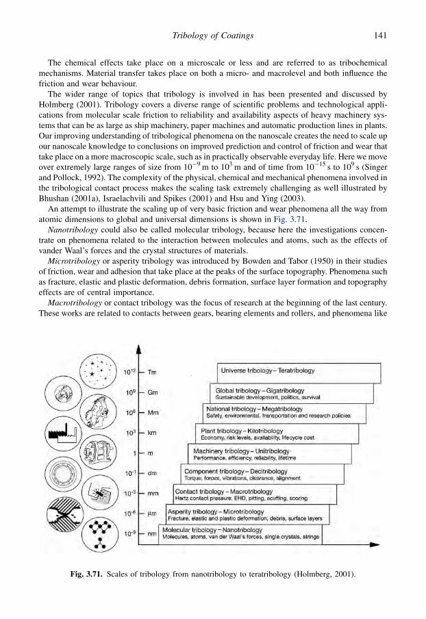
The chemical effects take place on a microscale or less and are referred to as tribochemicalmechanisms. Material transfer takes place on both a micro- and macrolevel and both influence thefriction and wear behaviour.
The wider range of topics that tribology is involved in has been presented and discussed byHolmberg (2001). Tribology covers a diverse range of scientific problems and technological appli-cations from molecular scale friction to reliability and availability aspects of heavy machinery sys-tems that can be as large as ship machinery, paper machines and automatic production lines in plants.Our improving understanding of tribological phenomena on the nanoscale creates the need to scale upour nanoscale knowledge to conclusions on improved prediction and control of friction and wear thattake place on a more macroscopic scale, such as in practically observable everyday life. Here we moveover extremely large ranges of size from 10�9 m to 103 m and of time from 10�15 s to 109 s (Singerand Pollock, 1992). The complexity of the physical, chemical and mechanical phenomena involved inthe tribological contact process makes the scaling task extremely challenging as well illustrated byBhushan (2001a), Israelachvili and Spikes (2001) and Hsu and Ying (2003).
An attempt to illustrate the scaling up of very basic friction and wear phenomena all the way fromatomic dimensions to global and universal dimensions is shown in Fig. 3.71.
Nanotribology could also be called molecular tribology, because here the investigations concen-trate on phenomena related to the interaction between molecules and atoms, such as the effects ofvander Waal’s forces and the crystal structures of materials.
Microtribology or asperity tribology was introduced by Bowden and Tabor (1950) in their studiesof friction, wear and adhesion that take place at the peaks of the surface topography. Phenomena suchas fracture, elastic and plastic deformation, debris formation, surface layer formation and topographyeffects are of central importance.
Macrotribology or contact tribology was the focus of research at the beginning of the last century.These works are related to contacts between gears, bearing elements and rollers, and phenomena like
Fig. 3.71. Scales of tribology from nanotribology to teratribology (Holmberg, 2001).
141Tribology of Coatings

Hertzian contact pressure, elastohydrodynamic lubrication and wear mechanisms clearly observableby the naked eye (such as scuffing, scoring, pitting).
Component tribology or decitribology is related to defining and measuring typical parametersoriginating from the interaction of components and related to their performance such as torque, forces,vibrations, clearance and alignment.
Machinery tribology or unitribology describes the performance-related phenomena for a system ofcomponents assembled in a machine or a piece of equipment. The parameters of interest are per-formance, efficiency, reliability and lifetime estimation.
Plant tribology or kilotribology deals with a whole system of machinery, structures and equipment –and how parameters such as costs, risk levels, availability and lifecycle costs are used.
National tribology or megatribology extends the effects and consequences on a nationwide per-spective to include parameters of relevance such as safety policy, research policy, transportationpolicy and environmental policy.
Global tribology or gigatribology considers the effects on a worldwide basis as one interactingsystem; effects dealt with are sustainable development, politics and cultural and human survival.
Universe tribology or teratribology is the largest perspective today that the authors can think of inthis scaling-up exercise. But what does this mean? Is it interactions of material in our cosmos? Is itmechanisms for space expansion? Or is it mechanisms for the creation of new life and cultures?
The scaling up from molecular phenomena all the way up to universe tribology is an interestingexercise because it shows that at all levels we have to deal with phenomena that are known to us tosome extent. In this sense, then, it shows that talking about ‘scaling up’ and ‘scaling down’ is relevantand important.
In the following we will focus on the scales in tribology which are most relevant in the design anduse of coated components and tools, which is the range from nanotribology to macrotribology. Whenthe tribological mechanisms in a coated contact are analysed, the macromechanical mechanismsshould first be considered in order to achieve an understanding of what kind of contact it is. Theeffects defined on the macromechanical level dominate the tribological behaviour. Subsequently, it isnatural to continue by considering the micromechanical and the chemical mechanisms and, finally, thematerial transfer mechanisms which are actually a result of the previous effects. In some applicationsthe understanding of physical phenomena on the nanolevel will explain the tribological behaviour. Inthe following we will discuss the tribological mechanisms according to the above approach.
3.4.2 Macromechanical friction mechanisms
The macromechanical tribological mechanisms describe friction and wear phenomena by consideringthe stress and strain distributions in the whole contact, the total elastic and plastic deformations theyresult in and the total wear particle formation process and its dynamics. In contacts with one or twocoated surfaces, four main parameters which control the tribological contact process can be defined.They are
1. the coating-to-substrate hardness relationship,2. the thickness of the coating,3. the surface roughness, and4. the size and hardness of debris in the contact.
The relationship between these four parameters will result in a number of different contact conditionscharacterized by specific tribological contact mechanisms (Holmberg, 1992b). Figure 3.72 showsschematically 12 such very typical tribological contacts when a hard spherical slider moves ona coated flat surface.
It is important to notice that the three geometrically related parameters, the film thickness, thesurface roughness and the wear debris, all typically appear in the same dimension range from 0.01 mm
142 Coatings Tribology

Fig. 3.72. Macromechanical tribological mechanisms in a contact with coated surfaces depend on four main parameters: the hardness relationship, the filmthickness, the surface roughness, and the debris in the contact. Characteristic tribological contact phenomena influencing friction are shown schematically inthe subfigures a–l.
14
3T
ribo
log
yo
fC
oa
ting
s
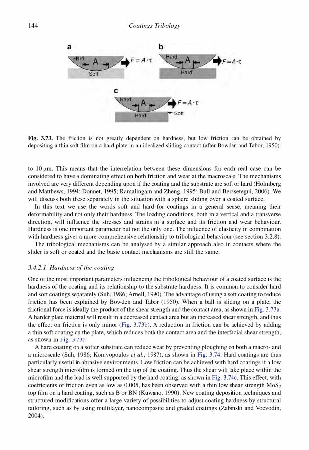
to 10 mm. This means that the interrelation between these dimensions for each real case can beconsidered to have a dominating effect on both friction and wear at the macroscale. The mechanismsinvolved are very different depending upon if the coating and the substrate are soft or hard (Holmbergand Matthews, 1994; Donnet, 1995; Ramalingam and Zheng, 1995; Bull and Berasetegui, 2006). Wewill discuss both these separately in the situation with a sphere sliding over a coated surface.
In this text we use the words soft and hard for coatings in a general sense, meaning theirdeformability and not only their hardness. The loading conditions, both in a vertical and a transversedirection, will influence the stresses and strains in a surface and its friction and wear behaviour.Hardness is one important parameter but not the only one. The influence of elasticity in combinationwith hardness gives a more comprehensive relationship to tribological behaviour (see section 3.2.8).
The tribological mechanisms can be analysed by a similar approach also in contacts where theslider is soft or coated and the basic contact mechanisms are still the same.
3.4.2.1 Hardness of the coating
One of the most important parameters influencing the tribological behaviour of a coated surface is thehardness of the coating and its relationship to the substrate hardness. It is common to consider hardand soft coatings separately (Suh, 1986; Arnell, 1990). The advantage of using a soft coating to reducefriction has been explained by Bowden and Tabor (1950). When a ball is sliding on a plate, thefrictional force is ideally the product of the shear strength and the contact area, as shown in Fig. 3.73a.A harder plate material will result in a decreased contact area but an increased shear strength, and thusthe effect on friction is only minor (Fig. 3.73b). A reduction in friction can be achieved by addinga thin soft coating on the plate, which reduces both the contact area and the interfacial shear strength,as shown in Fig. 3.73c.
A hard coating on a softer substrate can reduce wear by preventing ploughing on both a macro- anda microscale (Suh, 1986; Komvopoulos et al., 1987), as shown in Fig. 3.74. Hard coatings are thusparticularly useful in abrasive environments. Low friction can be achieved with hard coatings if a lowshear strength microfilm is formed on the top of the coating. Thus the shear will take place within themicrofilm and the load is well supported by the hard coating, as shown in Fig. 3.74c. This effect, withcoefficients of friction even as low as 0.005, has been observed with a thin low shear strength MoS2
top film on a hard coating, such as B or BN (Kuwano, 1990). New coating deposition techniques andstructured modifications offer a large variety of possibilities to adjust coating hardness by structuraltailoring, such as by using multilayer, nanocomposite and graded coatings (Zabinski and Voevodin,2004).
Fig. 3.73. The friction is not greatly dependent on hardness, but low friction can be obtained bydepositing a thin soft film on a hard plate in an idealized sliding contact (after Bowden and Tabor, 1950).
144 Coatings Tribology

In the following we will discuss in more detail the friction mechanisms present in the 12 contactsituations shown in Fig. 3.72. The contacts are characterized by the following typical tribologicalfriction-related contact phenomena: ploughing, shearing, load support from coating, substratedeformation, scratching, penetration, contact area and interlocking, asperity fatigue, particle embedding,particle entrapping, particle hiding and particle crushing.
3.4.2.2 Thickness of the coating
Coating thickness is an important parameter, influencing the stresses in the surface and the wear andfriction. The thickness of the coated surface layer is often easy to control during the deposition processbut the complexity of the contact mechanisms makes it difficult to find out which coating thicknesswould be tribologically optimal for a certain application. Below we will discuss the main frictionmechanisms related to coating thickness.
Shearing. First, we will consider a thin soft film on a hard substrate with smooth surfaces and nodebris present, as shown in Fig. 3.75b. When the film is thin enough, the effect of ploughing of the filmis small. The friction is thus determined by the shear strength of the film and the contact area, which isrelated to the deformation properties of the substrate. For an elastic sphere sliding on a hard plate witha soft coating, the contact area is determined by the Hertzian equation. Roberts (1989, 1990a) hasshown that in this situation the coefficient of friction can be expressed by the equation
Fig. 3.75. The contact of a hard slider moving on a hard flat surface coated by a soft coating ischaracterized by (a) ploughing for thick coatings and (b) shearing for thin coatings.
Fig. 3.74. (a) A hard slider moving on a soft counterface results in ploughing. (b) The ploughing can beinhibited by using a hard coating on the soft substrate. (c) A soft microfilm at the top of the hard coatingresults in decreased friction.
145Tribology of Coatings
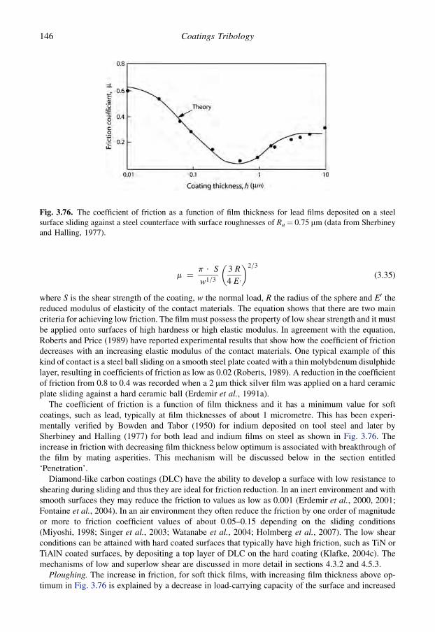
m ¼ p $ S
w1=3
�3 R
4 E;
�2=3
(3.35)
where S is the shear strength of the coating, w the normal load, R the radius of the sphere and E0 thereduced modulus of elasticity of the contact materials. The equation shows that there are two maincriteria for achieving low friction. The film must possess the property of low shear strength and it mustbe applied onto surfaces of high hardness or high elastic modulus. In agreement with the equation,Roberts and Price (1989) have reported experimental results that show how the coefficient of frictiondecreases with an increasing elastic modulus of the contact materials. One typical example of thiskind of contact is a steel ball sliding on a smooth steel plate coated with a thin molybdenum disulphidelayer, resulting in coefficients of friction as low as 0.02 (Roberts, 1989). A reduction in the coefficientof friction from 0.8 to 0.4 was recorded when a 2 mm thick silver film was applied on a hard ceramicplate sliding against a hard ceramic ball (Erdemir et al., 1991a).
The coefficient of friction is a function of film thickness and it has a minimum value for softcoatings, such as lead, typically at film thicknesses of about 1 micrometre. This has been experi-mentally verified by Bowden and Tabor (1950) for indium deposited on tool steel and later bySherbiney and Halling (1977) for both lead and indium films on steel as shown in Fig. 3.76. Theincrease in friction with decreasing film thickness below optimum is associated with breakthrough ofthe film by mating asperities. This mechanism will be discussed below in the section entitled‘Penetration’.
Diamond-like carbon coatings (DLC) have the ability to develop a surface with low resistance toshearing during sliding and thus they are ideal for friction reduction. In an inert environment and withsmooth surfaces they may reduce the friction to values as low as 0.001 (Erdemir et al., 2000, 2001;Fontaine et al., 2004). In an air environment they often reduce the friction by one order of magnitudeor more to friction coefficient values of about 0.05–0.15 depending on the sliding conditions(Miyoshi, 1998; Singer et al., 2003; Watanabe et al., 2004; Holmberg et al., 2007). The low shearconditions can be attained with hard coated surfaces that typically have high friction, such as TiN orTiAlN coated surfaces, by depositing a top layer of DLC on the hard coating (Klafke, 2004c). Themechanisms of low and superlow shear are discussed in more detail in sections 4.3.2 and 4.5.3.
Ploughing. The increase in friction, for soft thick films, with increasing film thickness above op-timum in Fig. 3.76 is explained by a decrease in load-carrying capacity of the surface and increased
Fig. 3.76. The coefficient of friction as a function of film thickness for lead films deposited on a steelsurface sliding against a steel counterface with surface roughnesses of Ra¼ 0.75 mm (data from Sherbineyand Halling, 1977).
146 Coatings Tribology

friction due to ploughing as shown in Fig. 3.75a. The coefficient of friction is increased due to both theelastic or plastic deformation of the film and to the increased contact area at the interface between thesphere and the coating where the shear takes place. The increase in friction with coating thickness hasbeen experimentally demonstrated for lead films (Tsuya and Takagi, 1964; Sherbiney and Halling,1977), for gold films (Takagi and Liu, 1967), for silver films (El-Sherbiny and Salem, 1986; Yanget al., 1999), for MoS2 films (Aubert et al., 1990; Wahl et al., 1999) and for Pb–Mo–S films (Wahlet al., 1999). By assuming that the real area of contact in sliding is virtually the same as that in staticloading, Finkin (1969) showed theoretically that the coefficient of friction for thick films is directlyproportional to the square root of the film thickness and inversely proportional to the square root of thenormal load.
A more general theory for the frictional behaviour of both thin and thick films was developed byHalling and El-Sherbiny (1978) and El-Sherbiny (1984). Even though the theory fits well to theirexperimental results, as shown in Fig. 3.76 the equation they propose for the coefficient of friction isnot very practical because it involves parameters which are not always easily estimated.
For thick, soft coatings the mechanism of ploughing will be very similar to that of soft bulkmaterials scratched by a hard indenter. Those tribological mechanisms have been described by severalauthors (e.g. Komvolpoulos, 1991b; Malzbender and de With, 1999; Lafaye et al., 2005; Felder andBucaille, 2006). In addition to the ploughing mechanism Hokkirigawa and Kato (1988a) also identifya wedge forming and a cutting mechanism depending on the degree of penetration and the shearstrength of the contact interface. These will influence the wear particle generation mechanism asshown by Wang and Kato (2003c). Particularly with elastic coatings, like rubber on a hard surface, thehysteresis effects on friction must also be taken into account (Adams et al., 1990).
Substrate deformation. We will now consider the situation with a hard smooth sphere sliding ona soft smooth substrate covered by a hard coating with no debris present as shown in Fig. 3.77. If thecoating is very thin, as in Fig. 3.77b, it is unable to support the load. The function of the coating isto separate the substrate from the counterface and to prevent ploughing by increasing the hardnessof the top layer of the surface. The latter effect has been considered to be very important (Shepardand Suh, 1982; Suh, 1986; Bull and Rickerby, 1990a; Zabinski and Voevodin, 2004). The preventionof ploughing reduces both the friction and the wear. The higher shear strength introduced at thecontact interface by the hard coating has, on the other hand, an increasing effect on friction insliding if no microfilms are formed as described above (Fig. 3.74). This explains the very highcoefficients of friction that often occur in sliding contacts of thin hard coatings. The increase infriction caused by increased shear strength generally seems to be more dominant than the reductionin friction due to decreased ploughing.
When loaded, the coating will deflect in accordance with the deformation of the substrate (Leroyand Villechaise, 1990; Korunsky et al., 1998; Jungk et al., 2008). The substrate will either deformelastically or plastically and, as the coating does not support the load, the deformation can be
Fig. 3.77. The contact of a hard slider moving on a soft flat surface coated by a hard coating is char-acterized by (a) load support from the coating for thick coatings and (b) substrate deformation for thincoatings.
147Tribology of Coatings

calculated as for bulk materials. For softer substrates the deformation will be considerable and willthus add a ploughing or hysteresis effect to friction. The repeated deflection of the coating may causefracture and fatigue cracks that destroy the coating or the substrate material. The influence of thesubstrate material’s hardness and elastic modulus on friction has been demonstrated for TiN coatedsurfaces (Komvopoulos et al., 1987; Komvopoulos, 1991b; Podgornik, 2000; Hainsworth and Soh,2003) and for DLC coated surfaces (Podgornik, 2000; Bandorf et al., 2003; Aoki and Ohtake, 2004;Nakahigashi et al., 2004). The load-carrying capacity was investigated by Podgornik (2000) andRonkainen (2001).
Load support from coating. When the hard coating is thicker, as shown in Fig. 3.77a, it can, because ofits stiffness, carry part of the load, and the deformation of the substrate will be smaller. The frictionalsituation is more favourable compared with the thin hard coatings because ploughing or hysteresiseffects due to substrate deformation will be relatively minor. Ploughing of the coating is prevented bythe high hardness, and the contact area between the coating and the sphere, where the shear takesplace, is reduced due to decreased surface deformation.
The coefficient of friction has been estimated theoretically by Rabinowicz (1967) as a function offilm thickness and junction diameter for soft films when the load is partly carried by a solid film andpartly by the substrate as shown in Fig. 3.78.
The influence of coating thickness on the load-carrying capacity of a TiN coated titanium substratewas shown by Komvopoulos et al. (1987) in a pin-on-disk test with a 6.35 mm radius spherical pinsliding at low velocity, between 0.0087 and 0.0353 m/s, on a flat surface of the same material.A 0.02 mm thick TiN coating showed high friction up to m¼ 0.65 due to the ploughing effect even atlow loads of 0.02–0.05 N while a 0.8 mm TiN coating on the same substrate had a coefficient offriction of only m¼ 0.1 even at loads of 0.2–2 N. They used boundary-lubricated conditions tominimize the effect of adhesive friction.
3.4.2.3 Roughness of the surfaces
As we already know, ideally smooth surfaces are rare in engineering applications. We will nowconsider friction effects for coated contacts with rough surfaces.
Scratching. For thick soft coatings the roughness of the substrate can be neglected if it is considerablysmaller than the thickness of the film and the film is stiff enough to carry the load, as shown inFig. 3.79a. However, in situations where the surface roughness is about one order of magnitudesmaller than the coating thickness, frictional effects have been observed. Both Roberts and Price(1989) and Aubert et al. (1990) have measured a decrease in the coefficient of friction for MoS2
Fig. 3.78. A hypothetical model of a junction where the load, w, is carried partly by the surface layer,which is about to be displaced, and partly by the substrate, which is about to deform plastically (afterRabinowicz, 1967).
148 Coatings Tribology

coatings deposited on rough surfaces compared with smooth surfaces, presumably without asperitypenetration of the coating. Possible explanations may be an improvement in the load-carryingcapacity by the coated substrate asperities or decreased shear strength by increased pressure at theMoS2 coating between the asperities and the counterface.
The slider with a rough surface will have a similar ploughing effect on friction as described abovefor smooth surfaces but in addition there will be surface roughness effects to be considered. Becauseof the softness of the coating there will be no increasing effect on the stress and strain fields at thecontact by the surface roughness (Sainsot et al., 1990). However, the asperities on the surface of thesphere will each contribute a microploughing effect on friction. This effect is most probably onlyminor as the results shown in Fig. 3.80 for bulk materials would indicate (Hisakado, 1976; Hwang andZum Gahr, 2003).
Penetration. For thin soft films on hard substrates, as in Fig. 3.79b, the influence of surfaceroughness is considerable. The penetration of asperities through the film will cause increased shearresistance and ploughing of either the substrate or the counterface with an increase in friction as
Fig. 3.79. The contact of a hard slider moving on a hard flat surface coated by a soft coating both withrough surfaces is characterized by (a) scratching for thick coatings and (b) penetration for thin coatings.
Fig. 3.80. The coefficient of friction as a function of surface roughness when hard asperities are ploughinga soft counterface (data from Hisakado, 1976).
149Tribology of Coatings

a result. This is illustrated by the left-hand side of the curve in Fig. 3.76. The increase in frictionstarts when the coating thickness decreases to the same level as the surface roughness (Sherbineyand Halling, 1977).
The effect on friction of asperity penetration through a soft coating has been modelled theoreticallyby Dayson (1971), Halling and El-Sherbiny (1978) and El-Sherbiny (1984), and the experimentalresults are in good agreement with the theory as shown in Fig. 3.76. The coefficient of friction isinfluenced by the hardness ratio of the film and the substrate, the ratio between the real area of contactfor the film and the substrate and material properties such as the yield stress to hardness ratio, the yieldto maximum shear stress ratio, the shear strength and the deformation mode.
Reduced contact area and asperity interlocking. When a rough surface is covered by a thick hardcoating the surface roughness may remain or be altered to some extent depending on the depositionmethod. When a hard rough slider is moving over such a surface the absence of larger elastic or plasticdeformations will result in the contact situation shown in Fig. 3.81a, where the slider is moving ona small number of asperity tops. The area of effective adhesion between the sliding surfaces has beenreduced to a few asperity contacts. This situation can only prevail with very hard and tough materialcombinations because the contact pressure at the asperities will be extremely high (Sainsot et al.,1990; Gong and Komvopoulos, 2003; Lindholm et al., 2006). In sliding with a hard rough surfaceagainst a smoother countersurface the initial friction is often low, due to the reduced contact area, andthen increases as wear of asperity tops increases the contact area (Wiklund et al., 1999a).
If the shear strength at the small number of asperity contacts is low the coefficient of friction will beextremely low. The suggested formation of a thin slippery microfilm on the top of a diamond coatingmay result in such contact conditions. Because of the high contact stresses and the brittleness of thecoating, a hard substrate is needed to carry the load. This explanation is supported by the very lowcoefficients of friction of 0.08, measured for a SiC ball sliding on a diamond coating by Jahanmir et al.(1989) and 0.05 for a monolithic single crystal diamond stylus sliding on a diamond coating measuredby Hayward and Singer (1990).
The friction may be considerably increased by asperity interlocking and breaking mechanisms ifboth surfaces are rough. This is typically the situation at the initial stage of diamond sliding ona diamond coating before running-in smoothing has taken place (Hayward et al., 1992), as shown inFig. 4.54.
Asperity fatigue. A hard slider moving on a thin hard coating covering a soft substrate will result inplastic or elastic deformation of the substrate material under the contact, as shown in Fig. 3.81b. In thecase of rough surfaces it results in an increased number of asperity contacts and decreased stresses atthe asperities because a greater number of asperities are carrying the load.
As the asperities are repeatedly loaded by the sliding counterface, there is a high probability offatigue failure. Delamination-type surface fatigue wear has been observed by Sue and Troue (1990)for steel sliding against TiN coatings. This fatigue is an important wear mechanism but does not
Fig. 3.81. The contact of a hard slider moving on a soft flat surface coated by a hard coating, both withrough surfaces, is characterized by (a) reduced contact area and interlocking for thick coatings and(b) asperity fatigue for thin coatings.
150 Coatings Tribology
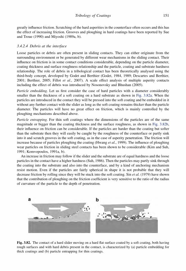
greatly influence friction. Scratching of the hard asperities in the counterface often occurs and this hasthe effect of increasing friction. Grooves and ploughing in hard coatings have been reported by Sueand Troue (1990) and Miyoshi (1989a, b).
3.4.2.4 Debris at the interface
Loose particles or debris are often present in sliding contacts. They can either originate from thesurrounding environment or be generated by different wear mechanisms in the sliding contact. Theirinfluence on friction is in some contact conditions considerable, depending on the particle diameter,coating thickness and surface roughness relationship and the particle, coating and substrate hardnessrelationship. The role of debris in a tribological contact has been theoretically analysed using thethird-body concept, developed by Godet and Berthier (Godet, 1984, 1989; Descartes and Berthier,2001; Berthier, 2005; Fillot et al., 2007). A scale effect analysis of multiple asperity contactsincluding the effect of debris was introduced by Nosonovsky and Bhushan (2005).
Particle embedding. Let us first consider the case of hard particles with a diameter considerablysmaller than the thickness of a soft coating on a hard substrate as shown in Fig. 3.82a. When theparticles are introduced in the contact they will be pressed into the soft coating and be embedded in itwithout any further contact with the slider as long as the soft coating remains thicker than the particlediameter. The particles will have no great effect on friction, which is mainly controlled by theploughing mechanisms described above.
Particle entrapping. For thin soft coatings where the dimensions of the particles are of the samemagnitude or bigger than the coating thickness and the surface roughness, as shown in Fig. 3.82b,their influence on friction can be considerable. If the particles are harder than the coating but softerthan the substrate then they will easily be caught by the roughness of the counterface or partly sinkinto it and scratch grooves in the soft coating, as in the case of asperity penetration. The friction willincrease because of particles ploughing the coating (Hwang et al., 1999). The influence of ploughingwear particles on friction in sliding steel contacts has been shown to be considerable (Kim and Suh,1991; Komvopoulos, 1991a, b).
An increase in friction may follow if the slider and the substrate are of equal hardness and the looseparticles in the contact have a higher hardness (Suh, 1986). Then the particles may partly sink throughthe coating into the substrate and also into the counterface, and by a kind of anchoring mechanismresist motion. Even if the particles are fairly spherical in shape it is not probable that they willdecrease friction by rolling since they will be stuck into the soft coating. Sin et al. (1979) have shownthat the contribution of ploughing on the friction coefficient is very sensitive to the ratio of the radiusof curvature of the particle to the depth of penetration.
Fig. 3.82. The contact of a hard slider moving on a hard flat surface coated by a soft coating, both havingrough surfaces and with hard debris present in the contact, is characterized by (a) particle embedding forthick coatings and (b) particle entrapping for thin coatings.
151Tribology of Coatings

If the particles in the contact are soft, then their tribological effect is quite different. Soft particleswith low shear strength trapped in the contact can carry part of the load and inhibit direct substrate-to-counterface contact, thus reducing friction (Grill, 1997; Voevodin et al., 1999b). A similar effect hasbeen observed by Yamada et al. (1990) who found that polymer particles can act very effectively toreduce friction. In contacts with MoS2 coatings or when Mo and S are present, MoO2 wear debris isproduced that has a very low shear strength and thus can act as a solid lubricant reducing the friction(Donnet, 1998a; Singer et al., 2003). Increased friction by generated and trapped wear particles hasbeen observed in, e.g., DLC against ceramic Al2O3–TiC (Wei and Komvopoulos, 1997) and DLCagainst steel (Samyn et al., 2006) sliding contacts.
Particle hiding. The introduction of small particles into the sliding contact of hard and rough surfaces,as shown in Fig. 3.83a, does not necessarily make the tribological mechanisms more severe. Theparticles can be hidden in the valleys formed by the asperities while the sliding takes place at theasperity tops. Thus the particles will have no great effect on either friction or wear. This effect has beendemonstrated for wear particles generated in carbon coatings sliding against a ceramic surface (Weiand Komvopoulos, 1997), small diamond onion-like particles in a sliding steel against silicon contact(Hirata et al., 2004) and fullerene particles in steel sliding against steel contact (Rappoport et al., 2005).
It is important to notice that reduced surface roughness of the surfaces may increase both frictionand wear if the particles cannot hide in the valleys and instead interact with the surfaces by scratchingand interlocking.
Particle crushing. When particles, large in relation to the surface roughness, are introduced betweentwo hard surfaces the result can be particle crushing, scratching or rolling as shown in Fig. 3.83b. Ifthe particles have a lower hardness than the surfaces, then they will be crushed and destroyed underthe load of the contact, with smaller debris and some increase in friction as a result. If the particleshave a higher hardness than the surfaces, they will be caught by the roughness of the surfaces withploughing and scratching resulting as described earlier.
The presence of hard particles between hard surfaces may in some cases even reduce the coefficientof friction. If the particles are fairly round in shape, hard enough to carry the load, and at least oneof the surfaces is smooth, the particles may act as rollers and reduce the coefficient of friction(Blomberg, 1993).
The debris in the contact may also change in its properties during the sliding action. In the slidingcontact of a TiN coating against a corundum ball, De Wit et al. (1998) observed that the wear debrisproduced by fretting was transformed during the sliding from amorphous debris into nanocrystallinerutile-like particles with a drop in the friction as a result. Wear debris formed in a contact witha multilayer (Ti,Al)N/TiN coating on steel substrate sliding reciprocating against a corundum ball wasobserved to become progressively more and more lubricious at increasing humidity. In sliding a steelball against two kinds of DLC (a-C:W and a-C:Cr) coated contacts, oxidized coating material was
Fig. 3.83. The contact of a hard slider on a soft flat surface coated by a hard coating, both having roughsurfaces and with debris present in the contact, is characterized by (a) particle hiding for thick coatings and(b) particle crushing for thin coatings.
152 Coatings Tribology
observed to be collected in the surface topography and it increased friction because of the higher shearresistance of the oxidized material (Svahn et al., 2003).
3.4.3 Macromechanical wear mechanisms
The macromechanical wear mechanisms can be analysed by using the same schematic representationfor typical tribological contact situations as was used to study the friction mechanisms (Fig. 3.72). The12 different contact situations can be grouped to represent eight characteristic wear mechanisms(Holmberg et al., 1992b) as shown in Fig. 3.84.
Plastic deformation. When a hard slider moves on a soft thick coating which is stiff enough to carrythe load, the result will be a groove in the coating as shown in Fig. 3.84a. The removal of material canbe calculated by the geometry of the contact. The situation from the wear point of view is very similarto the contact with a hard slider ploughing in a soft bulk material. That kind of contact has been treatedin detail in several textbooks on tribology and, for example, by Hokkirigawa and Kato (1988a) andKitsunai et al. (1990).
Plastic deformation was observed as the main wear mechanism when a slider moved on a planesurface coated with a layer of gold (Tangena, 1987, 1989; Tangena and Wijnhoven, 1988; Tangenaet al., 1988). Tangena and his co-workers correlated the calculated von Mises stresses averaged overthe contact width and the depth of the coating with the wear volume, using a theoretical model basedon low-cycle fatigue. Using finite element calculations they showed that the geometry of the system,the mechanical properties of the substrate and the contact load determine the mechanicaldeformations of the top layer. The theory was supported by experimental results (Fig. 3.85) whichshowed that if the average von Mises stress was above the yield stress of the coating, the wear in-creased enormously, indicating the importance of plastic deformation in the film. This process of low-cycle fatigue wear is related to the mechanisms known as ratchetting and delamination, as describedbelow, which have been previously discussed mostly in the context of uncoated surfaces.
In the sliding of a sphere on a soft coating three phases of plastic deformation have been identified,which represent a process of wear mode transition from ploughing to flowing and finally todelamination wear, as shown in Fig. 3.86. This was shown with a 5 mm radius diamond sphere slidingon a very thin carbon nitride coating by Wang and Kato (2003c). In the flowing wear mode, wearparticles were burnished from a plastically deformed CNx coating surface layer by flow wear. In flowwear mode, plastically deformed ‘filmy’ surface layers extrude from the edges and both ploughing andflowing create fine grooves during the process of horizontal plastic flow. If the filmy layers extrude tocover the fine grooves from the side, filmy wear particles are generated. If the filmy layers curltowards the bottom of the fine grooves, long and slender wear particles are generated. In thedelamination wear mode, wear particles were rapidly detached from subsurface layers of CNx bya low-cycle fatigue wear. Surface delamination results from brittle fracture around the maximumshear stress region or it may initially occur through microcracking in the deformed coating subsurfacelayer, where the maximum shear stress occurs, rather than along the coating/substrate interface. Thepropagation of microcracks into the deformed coated surface generates wear particles.
If the surface of the slider considered earlier is rough or if small debris is introduced into thecontact, the result is that the asperities or the trapped debris cause microploughing and microgroovesin the main groove. This effect can also be calculated (Hisakado, 1976; Sin et al., 1979) but itsinfluence on total wear is normally only minor (Hwang et al., 1999). With a theoretical modelEl-Sherbiny and Salem (1979) showed that the wear appears to be dependent on the surface texture ofthe system rather than on material properties during the initial wear when hard conical asperities areploughing a soft surface coating.
Adhesive and fatigue wear. Adhesive wear is to some extent present in several contact situations.Even if all other wear mechanisms have been eliminated by good tribological design some minor
153Tribology of Coatings

Fig. 3.84. The macromechanical wear mechanisms in a contact with coated surfaces depend on four main parameters: the hardness relationship, the filmthickness, the surface roughness and the debris in the contact. Characteristic wear processes are schematically shown in the subfigures a–h.
15
4C
oa
ting
sT
ribo
log
y

adhesive wear will still exist. Adhesive wear is typical of a hard sphere sliding on a thick hard coatingor on a hard substrate covered with a thin soft coating as shown in Fig. 3.84b. With repeated slidingcontacts the adhesive wear is often associated with large plastic strain accumulated close to the topsurface and low-cycle fatigue (Torrance, 1992; Yan et al., 2000), as shown in Fig. 3.50. The repeatedaccumulation of plastic strain is also frequently referred to as ratchetting (Kapoor et al., 1996;Kapoor, 1997).
The load-carrying capacity of soft films increases with decreasing film thickness and thinner filmshave a better resistance to adhesive wear because of the smaller real area of contact (Halling, 1986;El-Sherbiny and Salem, 1986). A thin soft film applied in the sliding contact between two hardsurfaces may remarkably improve the wear resistance of the contact. For example, the use of a 2 mmthick silver coating on a hard zirconia ceramic plate sliding against a ceramic ball reduced the wear ofthe ball by factors of 5 to 3300 and the wear of the coated plate was immeasurable (Erdemir et al.,1991a).
The wear process for thin soft coatings is generally complex. Often, especially for thin polymercoatings, the wear mechanism is a combination of adhesive wear and repeated plastic deformation.This has been observed by Fusaro (1981) for polyimide-bonded graphite fluoride films and byYamada et al. (1990) for polytetrafluoroethylene (PTFE) films. In addition, fatigue wear may beinvolved depending on the film material. Yamada et al. (1990) observed the detachment of thinfilms from the wear track after a number of passes for PTFE films and the detachment of flake-likewear debris for polyimide films. Very mild adhesive and fatigue wear conditions were observed byTakagi and Liu (1968) in a heavily loaded gold coated cylinder-on-plate test where coatings with
Fig. 3.85. Cross-section of the wear track for both evaporated and electrodeposited gold layers asa function of the von Mises stress averaged over the depth and the contact radius for 56 different contactsituations. The solid line is obtained from a wear model (data from Tangena, 1989).
155Tribology of Coatings

thicknesses of 5 to 20 mm improved the wear life by up to four orders of magnitude, although thefriction coefficient was as high as 0.6 to 0.8.
A soft thin film on a hard substrate can also be used to reduce delamination wear because of itsinfluence on the dislocation density at the outermost surface layer. A thin layer of a soft metaldeposited on a hard substrate can retard the wear of the harder substrate by preventing plasticdeformation and crack nucleation. If the soft layer is thicker than a critical value, delamination canoccur within this layer, forming loose wear particles which cause ploughing and further plastic de-formation. This mechanism has been experimentally demonstrated by Jahanmir et al. (1976) and Suh(1986) for the soft metals gold, silver, nickel and cadmium. They found that for an optimum filmthickness of 1 micrometre the reduction in wear rate can be even more than two orders of magnitudeas shown in Fig. 4.21 for a nickel coating on steel. Gold, nickel and cadmium coatings were reportedto be effective only in an inert atmosphere, but silver was effective also in air. A soft coating willreduce the surface tensile stresses that contribute to undesirable subsurface cracking and subsequentlyto severe wear (Spalvins and Sliney, 1994; Matthews et al., 2001).
Diamond-like carbon films are sometimes fairly soft and in a sliding contact adhesive wear is oftencombined with asperity fracture, chip and flake formation and micropitting. As the wear debrisbecomes trapped at the contact interface graphitization of amorphous carbon wear products changesthe interfacial surface, energy and shear strength and affects the steady-state tribological behaviour(Wei and Komvopoulos, 1997; Jiang and Arnell, 2000).
Fig. 3.86. A schematic model for three wear modes in plastic deformation of a soft coating: (a) normalload, (b) ploughing, (c) flowing wear and (d) delamination wear (after Wang and Kato, 2003c).
156 Coatings Tribology

It seems obvious that very thin films on the top of a surface will affect the work hardening processduring sliding at the top layer, but there is little information published on how this influences thetribological mechanisms.
Asperity scratching. In contacts with rough surfaces and thin soft films the mechanism of asperitypenetration and ploughing dominates. However, there are interesting examples showing that thesurface roughness of the substrate may influence wear even before penetration has taken place. Insliding experiments with a 1 mm thick MoS2 coating on a steel substrate the lifetime of the coatingincreased by one order of magnitude and the coefficient of friction decreased by about half when thesubstrate roughness was increased from Ra¼ 0.04 mm to 0.12 mm (Roberts and Price, 1989) as shownin Fig. 4.26. Possible explanations may be an improvement in the load-carrying capacity by the coatedsubstrate asperities or decreased shear strength caused by increased pressure in the MoS2 coatingbetween the asperities and the counterface.
Asperities on the surface of a rough slider moving on a hard substrate with a soft coating, as shownin Fig. 3.84c, penetrate the coating and slide directly on the substrate. If the asperities are harder thanthe substrate, they will also penetrate into the substrate and produce grooves by ploughing both in thecoating and in the substrate. A theoretical wear model for this contact situation was developed byEl-Sherbiny and Salem (1984) for predicting the wear rate of the coating and the substrate asa function of surface topography, contact geometry, material properties and operating conditions. Afair agreement between theory and experiments with lead, indium and tin films was reported.
When a relatively smooth slider moves on a rough substrate covered with a thin soft coating, thefirst stage in the wear process is a combination of plastic deformation and adhesive wear, whichdecreases the coating thickness until there is contact between the sphere and the substrate asperitiesthrough the coating. After that, the wear increases considerably because of both adhesive andscratching wear between the substrate asperities and the surface of the slider. This kind of wearsituation has been described by Fusaro (1981) for polymer films on steel substrates.
Particle scratching. We will now discuss the situation when hard particles of the same size as the filmthickness and the surface roughness are introduced into the contact of a rough sphere sliding on a roughsubstrate covered with a thin soft coating, as shown in Fig. 3.84d. The particles are caught by the surfaceroughness and cause microploughing and scratching both in the soft coating and in the hard substrate ina similar way to the effect of hard asperities penetrating the coating described earlier. A differencecomes from the fact that the particles are free to rotate in the contact and they are often considerablysharper than the asperity angles in engineering surfaces. The wear rate depends on the particle size. It issmall for very small particles, increases rapidly with increasing particle size and then stabilizes whenthe particles reach a critical size where a transition from a cutting wear mechanism to a slidingmechanism takes place as shown in Fig. 3.87. This mechanism has been described for bulk materials bySin et al. (1979), although it can be assumed that a soft thin coating does not change it very much.
If the particles in the contact are soft, their tribological effect is quite different. Soft particles withlow shear stresses trapped in the contact can carry part of the load and inhibit direct substrate-to-counterface contact, thus reducing both wear and friction. This has been observed by Yamada et al.(1990) who found that polymer particles can act very effectively to reduce wear and friction.
Coating fracture. The use of thin hard coatings is often a very favourable solution from the wear pointof view, but if the substrate is not hard enough to carry the load, plastic or elastic deformation will takeplace in the substrate under the contact. The increased stresses within the coating or at the interfacebetween the coating and the substrate, as the coating deforms along with the surface of the substrate,may be higher than the tensile or shear strength of the material, resulting in crack nucleation andpropagation. Such a contact situation is illustrated in Fig. 3.84e.
The harder the substrate is, the higher the loading which the coating can resist without failure byfracture because of increased resistance to deflection (Hedenqvist et al., 1990a). Increased loads canalso be resisted without failure with thicker hard coatings because of their load-carrying capacity
157Tribology of Coatings

which reduces deflection (Roth et al., 1987). With a softer substrate, cracks will occur in the coatingboth within the contact area and outside at the substrate material pile-up area as shown in Fig. 3.88(Burnett and Rickerby, 1987b; Miyoshi, 1989a; Page and Knight, 1989; Guu et al., 1996a, b; Linet al., 1996a, b; Bull, 1997; Korunsky et al., 1998; Yuan and Hayashi, 1999; Ligot et al., 2000;Podgornik and Wanstrand, 2005).
When a highly loaded sphere is sliding on a hard coating the friction originating from both shearand ploughing will result in tensile stresses behind the sphere and compressive stresses and materialpile-up in front of the sphere. This can result in several different cracking patterns depending mainlyon the geometry and hardness relationships as discussed in detail in section 3.3.5.
Even if the coating does not fracture and fail at the first pass when it is loaded by a slidingcounterface, repeated loading may result in fatigue cracks and failure. The lifetime of a thin coatingmay even be considerably longer than that of a thick coating, for several reasons. First, as shown inFig. 3.89, under similar deformation conditions, the thicker coating will experience high bend stresslevels. Second, since the coatings typically have columnar growth morphologies, any crack normal tothe surface will be large in a thick coating, and may exceed the critical crack length, whereas in a thincoating this may not be the case.
There is experimental evidence that in rolling contact fatigue tests hard coatings (TiN) with a filmthickness well below 1 micrometre have up to two orders of magnitude longer lifetime than 2 to 3 mm
Fig. 3.88. Fracture of a hard brittle coating on a soft substrate takes place in the contact area and at thematerial pile-up area around the contact. Directions of material flow are indicated by arrows.
Fig. 3.87. Wear rate for steel as a function of abrasive grit diameter for different normal loads (data fromSin et al., 1979).
158 Coatings Tribology
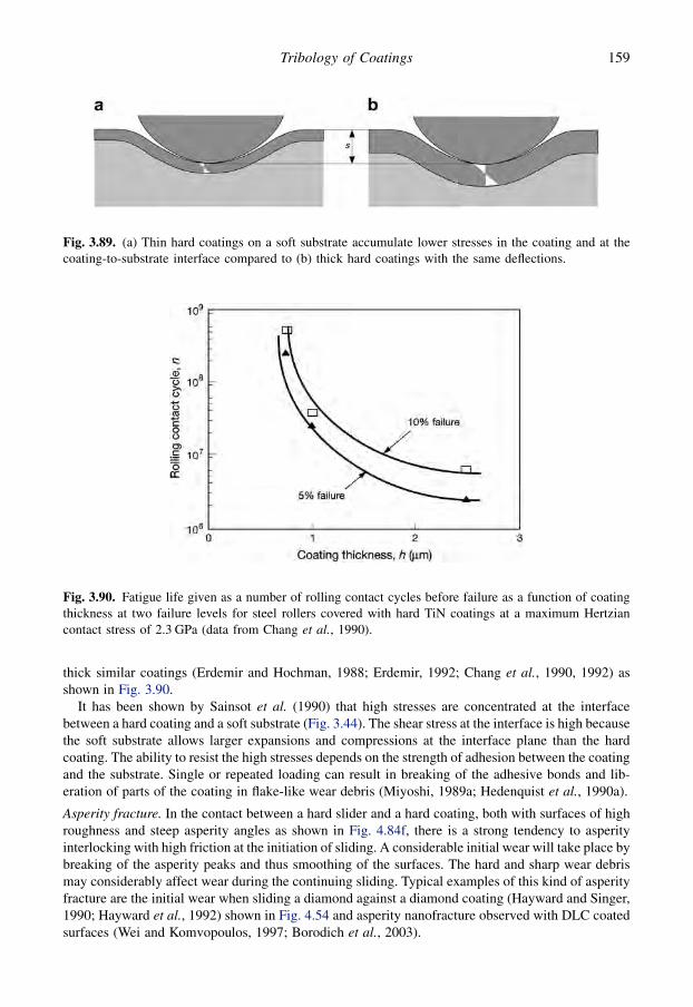
thick similar coatings (Erdemir and Hochman, 1988; Erdemir, 1992; Chang et al., 1990, 1992) asshown in Fig. 3.90.
It has been shown by Sainsot et al. (1990) that high stresses are concentrated at the interfacebetween a hard coating and a soft substrate (Fig. 3.44). The shear stress at the interface is high becausethe soft substrate allows larger expansions and compressions at the interface plane than the hardcoating. The ability to resist the high stresses depends on the strength of adhesion between the coatingand the substrate. Single or repeated loading can result in breaking of the adhesive bonds and lib-eration of parts of the coating in flake-like wear debris (Miyoshi, 1989a; Hedenquist et al., 1990a).
Asperity fracture. In the contact between a hard slider and a hard coating, both with surfaces of highroughness and steep asperity angles as shown in Fig. 4.84f, there is a strong tendency to asperityinterlocking with high friction at the initiation of sliding. A considerable initial wear will take place bybreaking of the asperity peaks and thus smoothing of the surfaces. The hard and sharp wear debrismay considerably affect wear during the continuing sliding. Typical examples of this kind of asperityfracture are the initial wear when sliding a diamond against a diamond coating (Hayward and Singer,1990; Hayward et al., 1992) shown in Fig. 4.54 and asperity nanofracture observed with DLC coatedsurfaces (Wei and Komvopoulos, 1997; Borodich et al., 2003).
Fig. 3.89. (a) Thin hard coatings on a soft substrate accumulate lower stresses in the coating and at thecoating-to-substrate interface compared to (b) thick hard coatings with the same deflections.
Fig. 3.90. Fatigue life given as a number of rolling contact cycles before failure as a function of coatingthickness at two failure levels for steel rollers covered with hard TiN coatings at a maximum Hertziancontact stress of 2.3 GPa (data from Chang et al., 1990).
159Tribology of Coatings

The surface asperity fracture process with a rough composite DLC coated soft aluminium alloysubstrate sliding against a tungsten carbide ball was analysed by Jiang et al. (1997a). Based on theirobservations they described the surface asperity fracture process as follows and also shown inFig. 3.91. When the contact pressure at the asperities within the substrate considerably exceeds theyield strength of the substrate, the substrate material is pushed to flow into the surrounding regions(Fig. 3.91a). The material flow is predominantly in the direction of the two sides of the wear track afterthe first two cycles of the contact since the substrate along the wear track has been work hardened.Locally, the substrate material tends to flow from asperities to grooves to flatten the surface. Highbending stresses act on the hard coating at positions at the asperity tops and at the groove bottom, andcracks are initiated at these sites and at the coating/substrate interface. With progress of sliding, weardebris are generated and accumulated somewhere on the wear track which will cause some of thefragmented coating to be pushed into the substrate (Fig. 3.91b). As sliding continues the surface isflattened and more fragments of the coating are either pushed into the substrate or removed from thesurface (Fig. 3.91c). Some of the coating fragments may get entrapped within the rubbing interface,grind into finer particles and finally mix up with the substrate material to form a mechanically alloyedhard surface layer (Fig. 3.91d). In parallel with these structural mechanical changes, at the same timea graphitization of the carbon at the top layer may take place.
Delamination. A more common situation is the sliding of a hard rough slider against a hard roughcoating with topography of low asperity angles, typically found in engineering surfaces, as repre-sented by Fig. 3.84g. The sliding action takes place at the tops of the contacting asperities. Theymainly deform plastically, although the overall contact stress may be less than the yield stress of thematerials, because the local stresses at the small asperity areas are much higher.
The high stresses at the asperities will thus generate dislocations, pile-up of dislocations and cracknucleation at only some 10 micrometres beneath the surface as described by Suh (1973, 1986) in thedelamination theory of wear and shown in Fig. 3.50. Because of the small plastic deformation of thesurface, a large number of cracks must be nucleated before a loose particle can form. The delaminated
Fig. 3.91. Schematic diagram showing wear processes during sliding wear of hard coatings on a softrough substrate at a high load (after Jiang et al., 1997a).
160 Coatings Tribology
particles are flake-like and may be some 100 micrometres long. This kind of flake-like wear debris hasbeen observed in the sliding contact between a steel slider and a hard coating (TiN) by Sue and Troue(1990) after about 200 sliding cycles; agglomerated particles being observed after 500 cycles. Thegeneration of flake-like wear debris probably by some kind of delamination mechanism has also beenobserved for softer materials like polyimide polymers (Yamada et al., 1990) and for DLC coatings(Lackner et al., 2003).
The wear rate in delamination wear can be calculated from an equation developed by Suh (1986)where it is given as a function of hardness, contact length, depth, average crack propagation rate, load,spacing of asperity contacts and crack spacing.
El-Sherbiny and Salem (1981) have worked on theoretically describing on a larger scale theasperity fatigue wear of hard rough coatings. They developed an equation where the wear rate isexpressed as a function of normal load, sliding speed, wear track width, standard deviation, meanradius and stiffness of surface asperities and the static yield strength of the multilayered material, butthe validity of their equation has not been definitely confirmed experimentally.
Delamination may also refer to the detachment of coating flakes from the substrate in repeatedsliding. This process was described by Kato et al. (1991) when a 33 mm radius diamond sphere wassliding on a 1 mm thick Al2O3 coated WC–alloy surface and is shown in Fig. 3.66. The delamination ofthe coating starts on both sides of the contact groove. By further repetition of sliding the coating at thegroove centre delaminates. Then subsurface lateral cracks propagate parallel to the surface, andthe coating is partially lifted. Branched cracks appear from the combined effect of frictional stress andthe residual stress. Perpendicular radial cracks on both sides of the groove and tensile-type cracks at itscentre help the lifting and detachment of the delaminated coating from the surface.
Wear particles or fragments that are very thin with dimensions less than the magnitude of thesurface roughnesses are not expected to influence the wear process, as shown in the lower part ofFig. 3.84g, because they can be hidden in the valleys between the asperities while the sliding actiontakes place at the asperity tops.
Abrasive wear. Abrasive wear is typified by a hard rough slider sliding on a hard rough coating, withhard particles of sizes larger than the magnitude of the surface roughness present in the contact, asshown by Fig. 3.84h. The trapped particles have a scratching effect on both surfaces, and as they carrypart of the load they will cause concentrated pressure peaks on both surfaces as they try to penetratethem. The high pressure peaks may well be the origin of crack nucleation in the coating (De Wit et al.,1998; Tricoteaux et al., 2003). A rolling movement of the particles, which sometimes may evendecrease the friction, is often present.
The sliding process will have an influence on the material properties of the counterface materialsurface. Because of work hardening, phase transitions or third body formation, the microhardness ofa steel wear surface can be about three times larger than the initial bulk hardness. In sliding abrasivecontacts with uncoated steel surfaces the main part of the wear particles is often smaller than 1micrometre in size (Kato, 1992). Abrasive wear has been observed in steady-state sliding of a steelslider, e.g. against a hard TiN coating, by Sue and Troue (1990), Malliet et al. (1991) and Franklin andBeuger (1992) and against DLC by Jiang and Arnell (2000), Borodich et al. (2003), Lackner et al.(2003) and Samyn et al. (2006).
Rolling contact fatigue. The contact conditions and wear mechanisms discussed above are all re-lated to a sliding contact. The situation in a rolling contact, as shown in Fig. 3.92, has manysimilarities but there are also clear differences. In a rolling contact the surface sliding component isminor and often limited to microsliding within the contact zone. Thus the adhesive mechanisms arenot so dominating and especially in the very common lubricated rolling contacts they are of minorinfluence. On the other hand, the wear in rolling contacts is typically dominated by the repeatedloading and deformation of the contact zone and fatigue wear dominates and limits the lifetime ofthe contact.
161Tribology of Coatings

Several wear mechanisms may be involved in a rolling contact. Typical are macropitting, micro-pitting, microdelamination, nanodelamination, mild polishing and severe polishing. These mecha-nisms were classified by Yonekura et al. (2005) in a study of rolling contact wear of hardened andtempered steel rollers coated with three kinds of low friction coatings, Cr2N, CrNþ nC andCrþWþ C:H, and rolling against a steel washer in a thrust bearing test.
The classification is shown in Fig. 3.93. Type (a) is delamination of the coating along and/orslightly beneath the coating/substrate interface with no polishing wear of the coating. Type (b) is mildpolishing wear of the coating and subsequent delamination along and/or slightly beneath the coating/substrate interface. Type (c) is micro-/nanodelamination of the coating outer layer in combinationwith polishing wear. Type (d) is macropitting, often referred to as the most typical rolling contactfatigue mechanism, and coating delamination. Type (e) is severe polishing wear and subsequentrolling contact fatigue. Type (f) is micropitting of the coating with pit diameter <10 mm. Micropittingis sometimes observed at an early stage of the rolling and may later reduce or disappear withouthaving any detrimental consequences. Yonekura et al. concluded that the most destructive failuremodes were the macropitting and the severe polishing with subsequent rolling contact fatigue.
3.4.4 Micromechanical tribological mechanisms
The origin of the friction and wear phenomena that we observe on the macrolevel is found in themechanisms that take place at the microlevel. The integration of all the micromechanical mechanismsresults in the macromechanical mechanisms discussed above.
The micromechanical tribological mechanisms consider the stress and strain at an asperity level,the crack generation and propagation, material liberation and single particle formation, as shown inFig. 3.94. In typical engineering contacts these phenomena are at a size level of about 1 micrometre orless down to the nanometre level.
Shear and fracture are the two basic mechanisms for the first nucleation of a crack and for itspropagation until it results in material liberation and formation of wear scar and a wear particle. Thesemechanisms were discussed in sections 3.2 and 3.3. In a detailed analysis of the micromechanicalmechanisms we need to use the very strict definition of the basic friction and wear mechanisms, asproposed by Holmberg et al. (2007). They classify friction in three basic mechanisms, adhesion,ploughing and hysteresis; and wear also in three mechanisms, adhesionþ fracture, abrasionþfracture and fatigueþ fracture, as shown in Fig. 3.95.
By definition wear always includes material removal. Fracture is here understood widely asa process starting from loss of cohesion between bond structures in the material, continuing as crackpropagation and resulting in debris being liberated from the surface. In this classification
Fig. 3.92. In a coated rolling contact surface deformation and fatigue dominate the wear process and theadhesive part has a minor role.
162 Coatings Tribology

tribochemical wear is not included. The tribochemical reactions are classified as surface modificationmechanisms since they represent chemical reactions that cause material modification, either im-provement or degradation of mechanical and physical properties, but do not include material removal.In tribochemical wear still one of the three above-mentioned basic wear mechanisms is the one thatcauses material removal (see Fig. 3.95).
Similarly, fatigue wear is divided into two phases. In the first phase only material modification istaking place, without material removal. During continuous loading of the surface the close-to-surfacematerial properties are slowly changed. The second phase, that is the material removal phase, starts
Fig. 3.93. Classification of coated roller wear mechanisms: (a) coating delamination, (b) mild polishing,(c) micro-/nanodelamination, (d) macropitting, (e) severe polishing and (f) micropitting (after Yonekuraet al., 2005).
Fig. 3.94. Micromechanical tribological mechanisms consider stress, strain, crack generation and prop-agation and single particle formation on a microlevel, typically this is what takes place in asperitycontacts.
163Tribology of Coatings

when the changed material can no longer withstand the loading and a crack is created; it grows,material is liberated and debris is formed.
3.4.4.1 A modelling approach
The above strict classification of basic friction and wear mechanisms is the basis for the modellingapproach by Holmberg et al. (2007) to understand the micromechanical tribological mechanisms.They analysed different contact situations of coated surfaces and indicated the tribologically domi-nating parameters that should be the focus in a modelling study.
Friction and wear are governed by the shear taking place at the top surface and in the deformedsurface layer, and by the elastic, plastic and fracture behaviour both at the top surface and in thedeformed surface layer. A thin coating is typically a part of this deformed surface layer. In addition,surface degradation may take place due to tribochemical and fatigue processes that influence thesurface strength and ability to withstand loaded conditions. Thus the crucial material parameters arethe elastic modulus, the hardness, shear strength and the fracture toughness on the top surface, in thecoating, at the coating/substrate interface and in the substrate under the coating, as shown in Fig. 3.96.
Fig. 3.95. The basic friction and wear mechanisms are related to adhesion, ploughing and hysteresis. Inthe case of wear these contact mechanisms result in material fracture, detachment and removal.
Fig. 3.96. Crucial material parameters and their location influencing on the micromechanical friction andwear behaviour.
164 Coatings Tribology
In this presentation, hardness, H, is used as symbol representing the resistance to plastic deformationdue to its common use, even if referring to the elastic–plastic constitutive response of the materialwould be the correct expression.
The presentation below is simplified to the conditions of a sphere, e.g. a spherical asperity, slidingover a flat coated surface, ideally smooth surfaces, homogeneous materials and with no contaminationor wear debris involved.
Adhesive friction is dominated by the shear taking place in the surface top layer or the shear in be-tween the two interacting surfaces. The coefficient of friction
ma ¼ f ðsuÞ (3.36)
Ploughing friction is dominated by the elastic and plastic behaviour of the coating and the substrate.The capacity of the substrate coating system to withstand deformation is frequently called load-carrying capacity. The coefficient of friction
mp ¼ f ðEc; Hc; Es; Hs; hÞ (3.37)
Hysteresis friction is mainly dominated by the elastic properties of the substrate but also to someextent by the elastic properties of the coating. The coefficient of friction
mh ¼ f ðEs; Ec; hÞ (3.38)
Adhesive wear is dominated by the fracture behaviour in the surface top layer, in the coating, at thecoating/substrate interface and in the substrate. The adhesive force, Fa, from the counterface tries totear off part of the surface material over the contact area A (Fig. 3.97). When surface roughness isincluded A will decrease and the adhesive wear typically decrease. The wear rate
k ¼ Vadh=w $ s ¼ f ðKu; Kc; Ki; KsÞ (3.39)
where Vadh is the volume of adhesive wear, w is the load and s is the sliding distance.The breaking of the material may take place at different locations in the surface depending on the
material strength at each location as shown in Figs 3.97b–e. Due to the depth of the debris detachmentthe result is
� top layer fragments dominated by Ku (Fig. 3.97b),� coating fragments dominated by Kc (Fig. 3.97c),� coating delamination dominated by Ki (Fig. 3.97d), or� substrate and coating debris dominated by Ks (Fig. 3.97c).
Abrasive wear is dominated by the geometrical collision of the two moving surfaces resulting in highstresses, material shear and fracture, and debris formation. The collisions may be due to hard asperityor third body ploughing or asperity collisions, as shown in Fig. 3.98. The wear rate
k ¼ Vabr=w $ s ¼ f ðKc; Ki; Ks; Hc; Hi; Hs; hÞ (3.40)
Due to the depth of the debris detachment the result is
� coating fragments dominated by Kc,� coating delamination dominated by Ki, or� substrate and coating debris dominated by Ks.
Fatigue wear is a result of material degradation where the strength of the material has decreasedto a level so that it can no longer withstand the repeated loading. The result is fracture, crackingand debris formation (Fig. 3.99). It is dominated by the elastic and fracture properties of thecoating, the coating/substrate interface and the substrate. The loading may be rolling or sliding. Thewear rate
165Tribology of Coatings
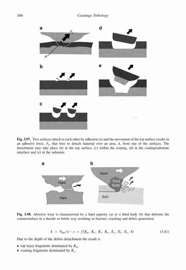
k ¼ Vfat=w $ s ¼ f ðKu; Kc; Ki; Ks; Ec; Ei; Es; hÞ (3.41)
Due to the depth of the debris detachment the result is
� top layer fragments dominated by Ku,� coating fragments dominated by Kc,
Fig. 3.97. Two surfaces attach to each other by adhesion (a) and the movement of the top surface results inan adhesive force, Fa, that tries to detach material over an area, A, from one of the surfaces. Thedetachment may take place (b) at the top surface, (c) within the coating, (d) at the coating/substrateinterface and (e) in the substrate.
Fig. 3.98. Abrasive wear is characterized by a hard asperity (a) or a third body (b) that deforms thecountersurface in a ductile or brittle way resulting in fracture, cracking and debris generation.
166 Coatings Tribology

� coating delamination dominated by Ki, or� substrate and coating debris dominated by Ks.
Surface modification is here considered separately from the pure wear mechanisms since it alone willnot result in material liberation. Still it is very important to consider in a wear process since it oftenprecedes the wear event and may be the reason for wear to start. Typical surface modificationmechanisms are chemical reactions taking place at the surface and material fatigue from repeatedloading.
Chemical reactions and sometimes even physical structural modifications, such as oxidation ofmetallic coatings, graphitization of DLC and crystallographic reorientation of MoS2 coatings, takeplace mainly at the top surface and influence the shear, su, and fracture, Ku, properties and thus theadhesive friction and adhesive wear. Sometimes also the whole coating structure and the coating/substrate interface be affected.
Fatigue is a result of repeated loading on the material that weakens the structure by includingcumulative damage to a level that it can no longer take the loading. The maximum stress peaks arenormally under the coating in the substrate because the coating layer is so very thin. Thus the substrateelastic properties, Es, and fracture toughness, Ks, are crucial. If the stress peaks are high and alsocloser to the surface, the elastic and fracture properties of both the coating and the coating/substrateinterface, Ec, Kc, Ei and Ki, may also be important.
This approach to simplify the basic mechanical friction and wear-related phenomena in the tri-bological contact of a coated surface was used by Holmberg and co-workers (Holmberg et al., 2003,2006a, b; Laukkanen et al., 2006; Ronkainen et al., 2007) as a basis for their 3D FEM modelling,stress and strain simulations and fracture calculations, also described in section 3.2.8. As the stresseshave been determined, their influence on crack growth calculated and the wear debris process defined,the single debris generation process can be integrated into multidebris wear particle generation asdiscussed in sections 3.3.7 and 3.3.8. This whole process is of course very complex and still today notwithin the range of being modelled in a holistic way.
3.4.4.2 Velocity accommodation
One other approach to studying the micromechanical wear mechanisms involves using the velocityaccommodation mode concept developed by Berthier et al. (1989) which is a logical framework forachieving a more complete fundamental understanding of the complex mechanical changes in atribological contact.
Velocity accommodation is defined as the manner in which the difference in velocity of two sur-faces in relative motion is accommodated across the interface (Berthier et al., 1989). This problemformulation is a fundamental question in all tribological studies. The place for velocity accommo-dation can be either in one of the solids, in the intermediate material or at the interface between them,as shown in Fig. 3.15. The intermediate material may be a liquid, a gas or loose particles. Berthier
Fig. 3.99. Fatigue wear is characterized by repeated loading of the coated surface resulting in cracking atthe surface in the coating, followed by fracture, material detachment and debris generation.
167Tribology of Coatings

et al. define four mechanisms describing how the velocity is accommodated; these are shown inFig. 3.15, and are elasticity, fracture, shear and rolling.
There is a principal advantage with this approach to tribological mechanisms compared with thetraditional ones. It is that here the mechanisms causing friction and wear are defined in terms wellknown from material science and mechanical engineering and the properties can thus be derived toknown parameters, such as strength, fracture toughness, Young’s modulus of elasticity or rollingresistance. The disadvantage is that when the whole contact system is split up into very small parts, itbecomes very difficult to find a way to handle the interactions of the different parts with each other.Another disadvantage is that still today we do not have satisfactory analytical models to describemany of the different mechanisms in velocity accommodation.
In the contact with a coated surface the situation is even more complex because the number of sitesfor velocity accommodation increases. Figure 3.100 shows that the velocity accommodation can takeplace also at the interface between the substrate and the coating, within the coating and withina microfilm on top of the coating.
The velocity difference between two surfaces can be accommodated by the elasticity of the surfacesin contact. This is the case when the surfaces adhere strongly to each other and the applied tangentialload is smaller than the load needed to cause slip. The junctions do not break but the elasticity allowssmall movements. This is typically the case in what is called false fretting, when a small amplitudereciprocating movement takes place without sliding.
With increased tangential loads, high tensile stresses at the surface generate cracks by fractureperpendicular to the surface. The cracks more easily allow movements of surface fragments ina tangential direction without shear in the adhered junctions. This may occur in both reciprocating andsliding contacts. The result is a tooth-like surface topography.
Shear of adhered junctions is the most common way for velocity differences between surfaces to beaccommodated. This takes place when the shear stress generated by the tangential load exceeds the
Fig. 3.100. The velocity accommodation in (a) an uncoated and (b) a coated sliding contact may takeplace in (1) the counterface, (2) its interface, (3) the intermediate material, (4) the top surface layer, (5) thecoating, (6) its interface to the substrate or (7) in the substrate. The influence of the velocity accommo-dation mechanisms on friction and wear is indicated in the table.
168 Coatings Tribology
shear strength at the weakest place of the contact junctions. In brittle solid materials the result istypically a lateral crack at the surface, whereas in fluids, sheets of the material at the molecular levelslide over each other just like cards in a pack. With plastic deformation of solids, as in ploughing,shear continuously takes place in the material, producing a new permanent shape for the surface.
With loose particles between the surfaces the velocity difference can be accommodated by therolling motion of the particles. In certain sliding contact conditions round or cylindrical wear particlesare produced and they may act in the contact as rollers if the surface roughness or softness does notinhibit the rolling.
Another approach to investigating the micromechanics of a coated surface is the multiscaleapproach presented by Yan et al. (2000). They used periodic unit cell-type continuum mechanicsmodels to predict localized deformation patterns at the scale of the coating thickness and the rate ofmaterials removal due to repeated sliding contact. The results indicate that the deformation of thecoating is controlled by the cyclic accumulation of plastic deformation, or ratchetting, at the coatingsubsurface. Based on a ratchetting failure criterion, a wear equation is proposed and applied toinvestigate parametrically the influence of the principal material, loading and surface roughnessparameters on the wear rate. The results revealed that the wear rate increases with contact pressure anddepends strongly on coating thickness and the toughness of the counterpart surface.
3.4.5 Tribochemical mechanisms
The chemical reactions taking place at the surfaces, during the sliding contact and also during theperiods between repeated contacts, change the composition and the mechanical properties of theoutermost surface layer. This has a considerable influence on friction and wear because they are toa great extent determined by phenomena like shearing, ploughing, cracking and asperity interlocking,all taking place at the surface top layer. The chemical reactions on the surfaces are strongly influencedby the high local pressures and the flash temperatures, which can often be up to 1000�C and for somehard ceramic surfaces even up to 2000�C, occurring at spots of asperity collisions. The formation oftribochemical surface films in tribological conditions has already been discussed in section 3.3.9.
The tribochemical surface mechanisms influence friction through the increase in contact temper-ature due to rubbing, increased surface reactivity through exposure of clean surfaces, transformationof surface material, ‘triboelectricity’ and direct mechanical stimulation of reactions. The influencemay be an increase or decrease of friction (Fischer, 1992; Donnet, 1998a; Neville et al., 2007; Wood,2007).
Mechanical wear mechanisms generally dominate the wear process in severe wear but in conditionsof mild wear tribochemical mechanisms become increasingly more important. Thermochemicalanalysis has been used for describing chemical reactions that accompany low wear and low friction onMoS2, TiN and TiC coated surfaces (Singer, 1991; Singer et al., 1991).
The tribochemical mechanisms that have been observed in tribological contacts can be divided intofour main surface phenomena for which the chemical effects are essential. They are:
1. the formation of thin microfilms on hard coatings,2. the oxidation of soft coatings,3. the formation of reactive boundary layers in lubricated contacts, and4. tribocorrosion of coated surfaces.
The tribological aspects of the mechanisms will be discussed below.
3.4.5.1 Formation of thin microfilms on hard coatings
Earlier we explained theoretically that the deposition of a soft thin coating on a hard substrate willreduce both the contact area and the shear strength at the contact and thus result in very favourable
169Tribology of Coatings

tribological conditions with low friction, as shown in Fig.3.73. This has been confirmed by severalexperimental investigations into layered materials or soft metals on hard substrates (e.g. Kuwano,1990; Erdemir et al., 1991a, b).
As a consequence of this, one would expect very unfavourable tribological conditions withhigh friction when a relatively soft substrate is covered by a hard coating. Surprisingly, however, thisis not necessarily the case. Low coefficients of friction down to 0.1 were reported for a hard titaniumnitride coating sliding against itself (Makela and Valli, 1985). Also, similarly, low values in drysliding contacts, down to 0.05, were measured for a DLC coating sliding against a sapphire coun-terface (Singer et al., 2003). It is obvious that there must be some explanation for this apparentcontradiction.
The very low friction behaviour of hard coatings can be explained by the formation of low shearstrength microfilms on the hard coating or on the asperity tips of the coating, as shown in Fig. 3.74 anda reduction in the real contact area. Thus, if we are studying the contact on a microscale, we againhave a soft coating on a hard substrate, but now it is the coating (e.g. TiN or DLC) which is playing therole of hard substrate and the formed soft microfilm is playing the role of a coating. It is obviouslyadvantageous for the substrate under the hard coating to be as hard as possible to avoid fracture of thebrittle coating by deformation, to improve the load support and to reduce the real area of contact.
Experimental results that confirm the above hypothesis can be found in the literature. The for-mation of a graphite-like microfilm on the hard DLC coating and the countersurface explains the lowcoefficients of friction reported for ceramic sliders sliding on DLC coatings (Singer et al., 2003), seesection 4.5.3.
Very common in practical applications is the formation of oxide microfilms on the top of hardcoatings. XRD, XPS and scanning Auger microscopy have indicated the formation of iron oxide(Fe2O3) and titanium oxide (TiO2) in the sliding contact between a TiN coated steel substrate anda steel slider and TiO2 formation in sliding TiN against TiN contacts (Sue and Troue, 1990; Singeret al., 1991; Franklin and Beuger, 1992). With the presence of ion implanted chlorine atoms insideTiN and TiC coatings, in situ formation of lubricious intermediate titanium oxides TiO and TinO2n�1
on the worn surfaces was observed in both dry sliding and machining tests (Aizawa et al., 2005). Thetheoretical background for the formation of oxides on titanium, titanium nitride and titanium carbidepresented by Gardos (1989) supports the hypothesis of microfilm formation.
Reduced friction has been observed, which indicates the formation of aluminium hydroxidemicrofilms, in the sliding contact of sapphire against a diamond coating (Hayward and Singer, 1990)and the formation of chromium oxide (Cr2O3) microfilms in the contact of a steel slider on a chromiumcoating (Gawne and Ma, 1989). Severe wear with spalling and oxidation as the main deteriorationmechanisms followed when tribofilms were generated by agglomeration of oxidation products, WO2
and Cr2O3, in a closed ring-on-ring sliding contact with WC/C coated Al2O3 sliding on Al2O3
(Blomberg et al., 1993).
3.4.5.2 Oxidation of soft coatings
In environments containing oxygen, such as air, a thin (about 1 to 10 nm thick) oxide layer is formedvery quickly on most metal surfaces. In particular, freshly cleaned (e.g. lapped or ground) surfaceswill acquire a layer of oxide in less than a few seconds. This applies to copper, iron, aluminium,nickel, zinc, chromium and several other metals.
The oxides formed may influence in different ways the tribological properties of the surfaces. Someoxide layers, like copper oxide, are sheared more easily than the metal, while others, like aluminiumoxide, form a very hard thin layer. Even if the oxide wear particles are hard, their abrasive effect is notnecessarily important because of their small dimensions compared with the roughness of the surfacesor their embedment into soft coatings, as shown in Fig. 3.72i. Sometimes the oxide particlesagglomerate to layers strong enough to carry the load.
170 Coatings Tribology

The oxidation of the top layer of coatings may improve the lubricity of the coating, as has beenobserved for lead coatings, where oxidation results in a top layer that is a combination of lead and leadoxide (Sherbiney and Halling, 1977) and for molybdenum disulphide coatings, where the oxidationresults in layers of MoO2, MoO3 and oxides of Mo reacted with the slider material (Fayeulle et al.,1990). Thin surface films of cadmium, silver and nickel have turned out to be ineffective for wear-reducing purposes in air because of oxidation, while the non-oxidizing gold was effective both in airand in inert environments when coated on steel substrates (Jahanmir et al., 1976).
3.4.5.3 Formation of reactive boundary layers in lubricated contacts
Tribochemistry has a central role in boundary lubrication where reactive components in the lubricantreact with the rubbing surface material and form lubricious surface layers with good load-carryingcapacity. The basic boundary lubrication mechanisms are presented in section 3.1.5 and the tri-bological effects with coated surfaces in section 3.4.7.
3.4.5.4 Tribocorrosion
In tribocorrosion the coated surface is normally surrounded by a corrosive fluid that causes chemicalattack on the surface. The wear and friction-related mechanisms involved have been reviewed byWood (2007). Three major wear–corrosion mechanisms of coated metallic surfaces were proposed byDearnley and Aldrich-Smith (2004) to be active in the situation of hard surface coatings like S-phaseand CrN on stainless steel substrate. They are schematically shown in Fig. 3.101. Type I relates tomild wear–corrosion interactions due to removal or damage of passive films on coatings and theirhealing by repassivation. Type II relates to large wear–corrosion interactions due to galvanic attack of
Fig. 3.101. Major types of tribocorrosion are (a) type I: where in hard coatings on metallic substrates thedamage of the passive film results in repassivation and healing, (b) type II: where in hard coated metallicalloys pitting or blistering of the coating culminates in mechanical fragmentation and coating removal, and(c) type III: where galvanic roughening of the counterface results in abrasion of the coating (after Dearnleyand Aldrich-Smith, 2004 and Wood, 2007).
171Tribology of Coatings

the substrate leading to blistering and removal of the coating under sliding contact. Type III relates toabrasion of the coating during subsequent sliding due to galvanic attack of the counterface which issubsequently roughened.
3.4.6 Nanophysical tribological mechanisms
Tribology is basically the science of breaking bonds within or between materials being in movementrelative to each other. The internal structure of materials comprises atoms organized and linked asmolecules, crystals and microstructures. Thus the origin to all friction and wear phenomena is to befound on an atomic or molecular scale. Nanotribology is the study of tribological phenomena onlength scales less than 100 nm. These phenomena are typically related to adhesion, interfacial friction,molecular scale solid and liquid surface films, molecular scale deformation, bond breaking, materialtransformation and detachment (Israelachvili, 1992; Dedcov, 2000; Gao et al., 2004; Bhushan, 1995,1999b, 2005).
Emerging experimental techniques and devices such as the surface force apparatus (SFA), theatomic force microscope (AFM), the friction force microscope (FFM), the scanning tunnellingmicroscope (STM) and other surface analysis methods have opened the possibility to study friction andwear phenomena on a molecular scale and to measure frictional forces between contacting molecules atthe nano-newton level (Israelachveli and Tabor, 1972; Overney and Meyer, 1993; Bhushan, 1999b).
Increased computational power has at the same time made it possible to study adhesion, frictionand wear processes by large-scale molecular dynamic simulations (MDS) of sliding surfaces and toinvestigate the atomic scale contact mechanisms, as shown in Fig. 3.102. The molecular dynamicsimulations consist of integration of the equations of motion of a system of particles interacting viaprescribed interaction potentials. The interatomic interactions that govern the energies and dynamicsof the system are characteristic of the system under investigation. Simulated phenomena includeelastic, plastic and yield processes, connective neck formation, wetting, reconstruction, solidification,atomic scale stick–slip and material transfer (Landman et al., 1992; Harrison et al., 1993, 1995; Perryand Harrison, 1996; Zhang and Tanaka, 1997; Gao et al., 2003; Tanaka et al., 2003; Yang andKomvopoulos, 2005; Schall et al., 2007).
3.4.6.1 Nanofriction and nanowear
Only some aspects of the complex nanophysical phenomena related to friction and wear have so farbeen investigated and the information is fragmented, related to some special cases of contacts andmaterials. We have some new information about the origin of sliding friction, that it stems fromvarious sources, including sound energy, and that static friction may arise from physisorbed mole-cules. An interesting observation is that the Amontons’ law, stating that the lateral friction force isdirectly proportional to the applied normal load independently of the apparent contact area, surfaceroughness and sliding velocity, is amazingly well obeyed for a wide range of materials such as wood,ceramics and metals, and over a wide range of contact scales, all from macro- to nanocontacts (Krim,2002b).
It has been observed in experimental measurements that friction values are often scale dependent.The values for friction on a nanoscale are much lower than those measured on a micro- and mac-roscale. The coefficient of friction for a 50 nm radius AFM Si3N4 tip sliding over three flat surfaces,graphite, natural diamond and Si(100), was 4 to 16 times lower compared to a 3 mm radius Si3N4 ballsliding over the same surfaces (Bhushan, 2005). Bhushan indicates four possible reasons for this:(1) in nanoscale experiments typically the contact stresses are higher, (2) the indentation hardness ishigher when measured on a small contact area and low loads, (3) the small apparent area of contactreduces the number of particles trapped at the interface and minimizes third body ploughing and(4) there is a larger range of contacting asperities coming in contact at the macroscale.
172 Coatings Tribology

There are very few studies published on wear mechanisms on the nanoscale. For a sliding diamondtip against a copper flat surface system Zhang and Tanaka (1997) used molecular dynamic simulationand found four distinct regimes of deformation on the atomic scale: a defect-free no-wear regime andthree wear regimes, the adhering, ploughing and cutting regimes, as shown in Fig. 3.103. The tran-sition between these regimes was governed by some dominating sliding parameters such as in-dentation depth, sliding speed, asperity geometry and surface lubrication conditions. It was interestingthat better lubrication, a smaller tip radius and lower sliding speed enlarge the no-wear regime. Theno-wear regime seems to exist for a wide range of contact conditions which indicates that no-wear ispossible even under chemically clean sliding conditions. In the cutting regime the frictional behaviourfollowed a proportional law. In all other regimes the variation of the frictional force was complex and
Fig. 3.102. Molecular dynamic simulation showing on an atomic level the interactions in a contact witha diamond surface sliding on a DLC coated diamond substrate. The diamond substrate is in blue, the DLCcoating in yellow, the diamond contersurface in grey, hydrogen atoms in green and unsaturated sp-hybridized atoms in the DLC film in red (from Gao et al., 2003, with permission). See Appendix B forcoloured picture.
173Tribology of Coatings

not possible to describe by a simple formula. This classification of wear mechanisms appears to be ona general level in harmony with the wear classification used by Kato and co-workers and extended tonanoscale contacts in AFM experiments by Wang and Kato (2003c).
3.4.6.2 Nanolayered coatings
There are very limited data about the tribological behaviour of surface coatings of thicknesses in thenanorange. There is some information from studies carried out by surface force microscopy andenvironmental scanning electron microscopy with a sliding diamond tip with 20 nm to 20 mm radiussliding against a silicon surface coated with a-C, Cr or TiC coatings in the thickness range of 1 to500 nm (Lu and Komvopoulos, 2001; Ma et al., 2003; Wang and Kato, 2003a). From the results itappears that in many respects the basic friction and wear mechanisms are similar to those observed ona microlevel.
In the comparison of a 10 nm thick a-C coated Si disk with 100 nm thick Cr and TiC coated Si discsthe a-C amorphous carbon coated surface had superior nanowear resistance due to the significantlyhigher hardness-to-elastic modulus ratio indicating a much higher elastic recovery at unloading(Lu and Komvopoulos, 2001). The deformation of the a-C film was purely elastic while it was elastic–plastic for Cr and TiC. The poorer wear resistance of the TiC films is due to a microscopic fractureprocess occurring at the grain size. The film nanowear resistance was related to the relative specificenergy, i.e. the energy dissipated during the nanowear process in the film divided by that dissipated inthe Si bulk material. With a diamond tip radius of 20 mm and 0.4 mm/s sliding speed the coefficient offriction increased at 50 mN load from 0.12 for an uncoated Si surface to 0.15 for Cr and TiC coatedsurfaces and to 0.2 for a-C coated surface. The increase in friction was less at higher loads up to400 mN. The tendency was for the coefficient of friction to increase at higher siding speeds, mostlikely due to strain rate effects. For elastic–plastic sliding, the general trend was for the coefficient offriction to decrease with increasing contact load. The nanowear tests indicate that in addition tonanohardness and H/E ratio, the microstructure, type of atomic bonding and the deposition processcontrolling film growth and residual stresses in the film exhibit a strong effect on the nanowearresistance for surfaces coated with nanolayered coatings.
In a film thickness range of 1 to 500 nm thick nitrogen-doped amorphous carbon coatings on silicondiscs Wang and Kato (2003a) showed that the transition of sliding mode from ‘no observable wearparticles’ to ‘wear particle generation’ was delayed with increasing film thickness. Two typical kindsof wear particles were observed in the in situ examination of the contacting surfaces, feather-like wearparticles and plate-like wear particles. The critical number of friction cycles before transition tookplace increased by 3 to 3.7 times when the coating thickness was increased from 10 to 100 nm.
Fig. 3.103. Four atomic scale deformation regimes identified by molecular dynamics simulation ofspherical diamond tip sliding on a flat copper surface from right to left (after Zhang and Tanaka, 1997).
174 Coatings Tribology

3.4.6.3 Diamond and diamond-like carbon surfaces
Two common coating materials, diamond-like carbon and diamond surfaces, have been of majorinterest in nanoscale studies because of their regular structure, inertness and low friction and wearproperties. Gao et al. (2003) showed by molecular dynamic simulations that the three-dimensionalstructure of an amorphous DLC film is paramount in determining its mechanical properties(Fig. 3.102). Particular orientations of sp2 ring-like structures create films with both high sp2 contentand large elastic constants. Films with graphite-like top layers parallel to the substrate have lowerelastic constants than films with large amounts of sp3-hybridized carbon.
Several of the most recent studies of DLC coatings indicate that the general explanation for theirextremely low coefficient of friction, down to m¼ 0.001 and below (Erdemir et al., 2000; Erdemir,2002) is related to five effects: (1) the surfaces are extremely smooth so asperity interlocking effectsare eliminated, (2) the surfaces and substrates are hard so ploughing effects are eliminated, (3) thedangling bonds of the carbon structure are attached to hydrogen atoms creating inert hydrophobicsurfaces that exhibit almost no frictional resistance, (4) strong and stiff carbon–carbon and carbon–hydrogen bonds which do not favour energy dissipation and (5) a positive atomic dipole charge of thehydrogen atoms out from both surfaces gives rise to repulsive forces (Harrison et al., 1995; Su andLin, 1998; Erdemir, 2002; Dag and Ciraci, 2004; Erdemir and Donnet, 2006). Actually no internalmaterial shear is taking place at all, the hydrogen planes just ‘fly’ over each other.
The atomic scale mechanisms of friction when two hydrogen-terminated diamond surfaces are insliding contact has been studied and the dependence of the coefficient of friction on load, crystal-lographic sliding direction, roughness and methane molecules as third bodies in the contact have beeninvestigated (Harrison et al., 1992, 1993, 1995, 1998; Perry and Harrison, 1996; Schall et al., 2007).Quantum chemical methods were used by Koskilinna (2007) to study the tribology of methylateddiamond and cubic and hexagonal boron nitride and tribochemical reactions were found to occur inthe contact.
3.4.6.4 MEMS applications
The scaling-up of the nanomechanical explanations of contact mechanisms to practically usefulconclusions on a macroscale is a most challenging and complex task and will take many years. Alreadythere exist practical applications on a nanoscale where the increasing knowledge of tribologicalnanomechansims can be used. This has resulted in the development of microelectromechanical systems(MEMS) such as motors, transducers, gears and bearings of sizes in the micrometre range (Bhushan,1998b, 2005; Krim, 2002b). For these extremely small components silicon has been used in the earlyapplications for production reasons but studies have shown that tribological improvements can beachieved by using polycrystalline diamond or MoS2 thin coatings or hydrogenated diamond-likecarbon coatings (Donnet, 1995; Beerschwinger et al., 1995; Gardos, 1996).
Today we are only at the very beginning of understanding the nanomechanical tribological contacteffects that explain the origin of friction and wear and there is no doubt that in the near future manynew theories and explanations for the origin of tribological phenomena will become available.
3.4.7 Lubricated coated contacts
Most of the information available on the tribological behaviour of coatings originates from experi-ments carried out in a normal laboratory environment and in dry conditions, which means that nolubricant is purposely brought to the contact. However, oil lubrication is common in many practicaltribological applications and it offers a convenient way of further decreasing both friction and wear.The general mechanisms of lubrication in contacts in relative motion are described in section 3.1.5.
175Tribology of Coatings

3.4.7.1 HD and EHD lubrication
In hydrodynamic (HD) lubrication the lubricant film separates the moving surfaces from each otherand the effect of coatings on the surfaces is mainly limited to the mixed lubricated start-up and slow-down situations when contact between the surfaces occurs. Typical for elastohydrodynamic (EHD)lubrication is a considerable elastic deformation of at least one of the surfaces and this must be takeninto account when using coatings in such contacts. As we have seen earlier in Chapter 3 very thincoatings may well deflect with the surface without fracture and failure. In general, an elastohy-drodynamic or mixed lubricated contact will have a more favourable wear behaviour than a similardry contact (Habig et al., 1980; Roth et al., 1988; Boving et al., 1983; Podgornik et al., 2004).Examples of extended lifetimes of elastohydrodynamically lubricated rolling contact bearings by theuse of thin hard coatings is described in Chapter 7.
Soft elastic coatings such as elastomeric or polymeric layers have been suggested to be used inelastohydrodynamically lubricated contacts to improve the lubrication conditions (Cudworth andHigginson, 1976). Gabelli and Jacobson (1990) used a soft rubber layer in the cage contact of a rollingelement bearing and observed an improved lubrication performance by an increased lubricant filmthickness, which was five to ten times thicker than that in the raceway contact.
3.4.7.2 Lubrication introduced into a coated contact
A very general observation is that when a lubricant is introduced into a coated moving contact inboundary or mixed lubricated conditions both the friction and the wear will decrease (Jamal et al.,1980; Komvopoulos et al., 1987; Bull and Chalker, 1992; Ajayi et al., 1992). This is not surprisingbecause the boundary lubricant film will carry part of the load and the shear strength of a liquid is withfew exceptions always lower than the shear strength of junctions between two solids in contact.
3.4.7.3 Coating introduced into a lubricated contact
It is, however, both more interesting and more important to see how the use of a coating affects thefriction and wear behaviour in a lubricated contact compared to a similar uncoated lubricated contact.The answer to this question is neither simple nor obvious.
There are several published experimental results that show decreased friction and wear due to theuse of coatings in lubricated contacts compared to similar uncoated contacts (e.g. Boving et al., 1983;Liu et al., 1991; Ajayi et al., 1992; Ronkainen et al., 1998a; Jacobson and Hogmark, 2001; Ajayiet al., 2003; Mabuchi et al., 2004; Podgornik et al., 2003, 2004, 2006a; Iliuc, 2006) but the oppositebehaviour has also been reported (Jamal et al., 1980; Bull and Chalker, 1992; Podgornik et al., 2003;Kalin and Vizintin, 2006a; Kalin et al., 2004) and in some investigations there was no clear differenceobserved at all (Komvopoulos et al., 1987; Vercammen et al., 2004).
The complexity of this problem is due to the several tribological contact mechanisms that aresimultaneously involved. The tribological behaviour of the contact will depend on which of thesemechanisms have a dominating role in the specific contact being studied. In boundary lubricated steelcontacts a boundary film will cover the surfaces as described in section 3.1.5. The strength of thechemical or physical bonds between the boundary film and the substrate will have a major influenceon the wear and load carrying properties of the contact. This is the reason for using chemicallyaggressive additives such as sulphur, phosphorus or chlorine in lubricating oil so that they chemicallyreact with the steel surface to form a strong boundary film.
3..4.7.4 Lubricant additive reaction to coated surface
If one of the surfaces is covered by a coating, the strength of the boundary film formed will depend onthe strength of the bonds it can form to the coating material. It has been observed that with a sputtered
176 Coatings Tribology

TiN coating on a steel surface there will be no chemical interaction between the TiN surface and theoil additives (not specified in the article) and thus the formation of a boundary film will be prevented(Ajayi et al., 1992). Figure 3.104 shows that the wear behaviour depends on what kind of lubricant isused (Bull and Chalker, 1992). With most lubricants the use of a TiN coated M2 steel disk has slightlyincreased total wear compared to uncoated steel discs sliding against a steel ball in ball-on-diskexperiments. In contradiction to this, Sander and Petersohn (1992) observed decreased friction anddecreased wear rate when using TiN coated steel plates instead of uncoated steel in oil lubricatedoscillating ball-on-plate tests.
Several investigations with DLC coated surfaces indicate that the normal extreme pressure andanti-wear additives function in a coated contact, especially if one of the surfaces is steel or the DLCcoating is doped by a metal. However, no major difference in the influence of the oil type, mineral,
Fig. 3.104. The disk and sphere wear rate for different lubricants in ball-on-disk tests with (a) a steelsphere sliding against uncoated steel, (b) steel sphere against a TiN coated steel disk and (c) an aluminasphere against a TiN coated steel disk with a sliding velocity of 0.1 m/s and load of 2 N (data fromBull and Chalker, 1992).
177Tribology of Coatings

synthetic or vegetable oil, on the tribological behaviour has been observed (Ronkainen et al., 1998a;Jacobson and Hogmark, 2001; Ajayi et al., 2003; Kalin and Vizintin, 2006; Kalin et al., 2004;Vercammen et al., 2004; Barriga et al., 2006; Podgornik et al., 2006a).
The addition of metals into the DLC structure improves the chemical reactivity of the rubbingsurface and it can react with the lubricant additives and form lubricious reaction layers. This has beenshown by Miyake et al. (2004) for Ti, Fe and Mo doped DLC surfaces sliding against a steel ball inzinc dialkyl dithiophosphate (ZDDP) and molybdenum dithiocarbamate (MoDTC) additivecontaining lubricant environment. By varying the metal target area during the coating depositionprocess they could control the amount of metal in the coating so that the quantity of metal increasedwith the increasing area ratio of the target. Figure 3.105 shows that for all three metal doped structuresthe coefficient of friction decreased from 0.2 to the range of 0.03 to 0.08 with only a very smallinfluence of amount of added metals. Improved wear properties in lubricated conditions of metaldoped coatings has also been reported by Ronkainen et al. (1998a) for Ti doped DLC and byPodgornik et al. (2004, 2006a) for W doped DLC.
3.4.7.5 Boundary lubricated coated contact
Basic mechanisms involved in a boundary lubricated contact with a rigid cylindrical slider moving ona coated elastic or plastic plate have been described in a mathematical friction model by Komvopoulos(1991b). His elastic friction model accounts for the shear properties of the lubricant, the ratio of thelayer thickness to the size of the asperity contacts, and the elastic properties of the layer and thesubstrate. The plastic friction model accounts for interfacial adhesion and ploughing effects and it isshown that the coefficient of friction is a function of the relative size and shape of the ploughing hardwear particles and work-hardened asperities, the interfacial shear stress, the shear strength and strainhardening properties of the substrate and the steady-state surface topography. Predictions ofcoefficients of friction by the models are in fair agreement with experimental results including 0.01 to0.13 mm thick oxide coatings on aluminium and chromium and TiN coatings on titanium and steelsubstrates as shown in Fig. 3.106.
The experimental observations of Komvopoulos (1991a), using oxidized aluminium, oxidizedchromium on steel (AISI 1095), TiN coated steel and TiN coated titanium, and coating thicknesses inthe range of 0.004 to 0.8 mm, show that the dominating contact parameters are the coating thickness,surface roughness, coating microstructure, the magnitude of the normal and friction traction arising atthe asperity junctions, and the mechanical properties of the layer and the substrate. In mild sliding
Fig. 3.105. The coefficient of friction for metal doped and pure DLC coatings sliding in lubricant withMoDTC additives. The metal target area is correlating with the quantity of metal added to the DLCcoating structure (data from Miyake et al., 2004).
178 Coatings Tribology

conditions without disruption of the coating the friction coefficient was about 0.1 and wear trackswere indistinguishable from the virgin surface. The principal deformation mode at the asperitycontacts was elastic and the predominant friction mechanism was the shear of the boundary lubricant.Severe contact conditions with fragmentation and removal of the coating resulted in high friction,extensive surface damage and ploughing due to wear debris formation. The ploughing was due to wearparticles trapped between the sliding surfaces, or the work-hardened asperities.
3.4.7.6 One or two surfaces coated
There is very obviously a difference if one or both of the surfaces in a lubricated sliding contact arecoated. It would agree with the earlier observations that it is more favourable to have a chemicallyless-reactive coating on only one of two steel surfaces to allow a strong chemical boundary film to beformed on the surface left uncoated. This assumption is supported by the experimental observations ofBoving et al. (1983). They tested CVD deposited TiN, TiC and (Cr,Fe)7C3 coatings with a ball-on-cylinder lubricated test apparatus and found that, in general, combinations of uncoated balls andcoated rings perform better than combinations of coated balls and coated rings. By far the bestperformance in terms of load-carrying capacity was found with a combination of uncoated steel ballswith TiN coated rings, as shown in Fig. 3.107.
In contradiction with the above statement are the results of Jamal et al. (1980) from lubricated pin-on-disk tests showing low coefficients of friction and low wear with both surfaces coated by TiN orTiC compared with higher values for only one surface coated and the other of uncoated steel. For
Fig. 3.106. Comparison between theoretical and experimental friction coefficients obtained from plasti-cally deformed boundary lubricated surfaces with oxide and nitride coatings on various substrates and ofvarious thickness ratios sliding in pin-on-disk testing against similarly treated surfaces. Here h is coun-tersurface spherical/conical tip penetration depth, r is tip radius, Q is sharpness angle, s is the shear stress,ks is the shear strength, n is the strain hardening coefficient and K is a material strain constant (data fromKomvopoulos, 1991b).
179Tribology of Coatings

a-DLC and W-DLC coated steel surfaces Kalin and Vizintin (2006) reported about 50% lowercoefficient of friction for the sliding of an a-DLC/a-DLC contact compared to steel/steel, steel/a-DLC,steel/W-DLC and W-DLC and W-DLC contacts while the lowest wear was found for steel/steel, steel/a-DLC and a-DLC/a-DLC contacts. Their results do not really give any clear indication on which ofthe two contacting surfaces it is more beneficial to coat.
Based on a large series of lubricated cross cylinder sliding tests with 2 mm thick W alloyed lam-inated WC/C structured DLC coatings on steel substrates with synthetic oil including no extremepressure or anti-wear additives Jacobson and Hogmark (2001) concluded with the recommendationthat it is most advantageous to coat only one of the two surfaces because this gives the best conditionsfor running-in. They explain the favourable tribological effect of DLC coating in a lubricated contactwith the formation of a synergistic tribofilm. Mild wear and transfer of DLC coating material, togetherwith chemical reaction products formed by additives in local areas not covered by coating, worktogether in reducing friction and wear. This is supported by the results from Podgornik et al. (2003)showing the lowest friction and lowest wear in cross cylinder test when only one of two sliding steelsurfaces was coated with WC doped DLC coating and using a suitable extreme pressure (EP) or anti-wear (AW) additive, as seen in Fig. 3.108. The friction was higher when using pure poly-alpha-olefine(PAO) synthetic oil and a fully formulated gear box oil (GL-4).
3.4.7.7 Rough surfaces and wear debris
There are, however, other effects that influence the tribological behaviour in coated lubricated con-tacts. Ajayi et al. (1992) found that a major difference between TiN coated and uncoated lubricated
Fig. 3.107. Load-carrying capacity of partial EHD and boundary lubrication films in lubricated IRG ball-on-cylinder tests with an uncoated, TiN, TiC and (Cr,Fe)7C3 coated steel specimen at a sliding velocity of0.5 m/s (data collected from Boving et al., 1983).
180 Coatings Tribology
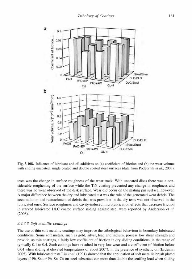
tests was the change in surface roughness of the wear track. With uncoated discs there was a con-siderable roughening of the surface while the TiN coating prevented any change in roughness andthere was no wear observed of the disk surface. Wear did occur on the mating pin surface, however.A major difference between the dry and lubricated test was the role of the generated wear debris. Theaccumulation and reattachment of debris that was prevalent in the dry tests was not observed in thelubricated ones. Surface roughness and cavity-induced microlubrication effects that decrease frictionin starved lubricated DLC coated surface sliding against steel were reported by Andersson et al.(2008).
3.4.7.8 Soft metallic coatings
The use of thin soft metallic coatings may improve the tribological behaviour in boundary lubricatedconditions. Some soft metals, such as gold, silver, lead and indium, possess low shear strength andprovide, as thin coatings, a fairly low coefficient of friction in dry sliding conditions, in the range oftypically 0.1 to 0.4. Such coatings have resulted in very low wear and a coefficient of friction below0.04 when sliding at elevated temperatures of about 200�C in the presence of synthetic oil (Erdemir,2005). With lubricated tests Liu et al. (1991) showed that the application of soft metallic brush platedlayers of Pb, Sn, or Pb–Sn–Cu on steel substrates can more than double the scuffing load when sliding
Fig. 3.108. Influence of lubricant and oil additives on (a) coefficient of friction and (b) the wear volumewith sliding uncoated, single coated and double coated steel surfaces (data from Podgornik et al., 2003).
181Tribology of Coatings

against a steel counterface and considerably decrease the coefficient of friction, as shown in Figs 4.12and 3.109. The lubricant was paraffin oil without additives. With higher substrate hardness the co-efficient of friction decreased and the scuffing load increased. For Pb coating thicknesses less than16 mm there was no appreciable effect of the coating thickness on either the coefficient of friction oron the scuffing load. However, for the Pb–Sn–Cu layers thicker than 12 mm they found a significantincrease in the scuffing load with increasing coating thicknesses.
3.4.7.9 DLC coated and lubricated sliding contacts
The tribological behaviour of DLC coated surfaces in lubricated conditions are of great interest due totheir wide commercial applicability. Still they are not well understood and some of the availableinformation seems even contradictory. This is due to the complexity of the contacting mechanisms. Insection 4.5.3 we will show that the dominating friction and wear mechanisms for DLC coated contactsare very different depending in the governing contact scale, see Fig. 4.89. The shear mechanism in thecontact may involve asperity interactions, transfer layer generation, surface graphitization andhydrogen attachment to carbon atom dangling bonds. The lubrication adds the possibility of part ofthe load being carried by and the movement sheared in a pressurized lubricant film or a surface filmformed by chemical reaction between surface material and lubricant additives. The outcome of thecontact in the form of friction and wear depends entirely on which of these mechanisms in the studiedspecific conditions can function and dominate over the other.
If a lubricant is introduced in a rough DLC or diamond coated macroscale contact withouthydrodynamic effects where the asperity interactions dominate, no larger effect on friction and wear isexpected (Fig. 4.89a). On the other hand, in DLC coated nanoscale contacts with superlubricity(Fig. 4.89c) where the shear is taking place between two highly hydrogenated physically smoothsurfaces the introduction of a liquid will only disturb the repulsive hydrogen layer interactions andincrease friction and wear (Andersson et al., 2003a; Erdemir, 2005).
However, the largest interest with regards to practical applications is related to the mechanismsoccurring at the microscale (Fig. 4.89b). Here it is important to study and understand the function and
Fig. 3.109. Influence of soft metallic coatings on the coefficient of friction in lubricated ball-on-disk tests.The substrate hardness was 535 HV and the sliding speed 0.97 m/s (data from Liu et al., 1991).
182 Coatings Tribology

interaction between three partly competing mechanisms: the graphitization of the top layers that offerslow shear, the formation of chemical reaction layers offering low shear and high load-carryingcapacity, and the build-up of a transfer layer on the counterface, often combined with graphitization,offering a smooth platform for shear. These interactions are not well understood but some detailedstudies give indications and are presented below.
In lubricated conditions a boundary reaction film was built up on a steel ball surface sliding againstDLC coatings with low friction properties quite similar to dry contacts (Fig. 4.83) with the samesurfaces (Ronkainen et al., 1998a; Ronkainen, 2001). In the dry contact the transfer layer formationand graphitization mechanisms had the same low shear effect as the boundary films. With lubricationno transfer layers were observed and it is understood that in these conditions the boundary lubricationmechanisms took the dominating role.
There is also a difference in the behaviour of DLC coatings in lubricated conditions depending ontheir structure. Figure 4.83 shows that with three kinds of DLC coatings hydrogen-free (a-C) andhydrogenated (a-C:H) carbon coatings had a low coefficient of friction in dry sliding, 0.15 and 0.22,which was further decreased by 10–40% under boundary lubrication. The a-C:H(Ti) coating exhibitedgood self-lubricated properties with a coefficient of friction of 0.10 in dry sliding and the a-C filmshad the lowest coefficient of friction in water and oil lubricated conditions, 0.03 and 0.08,respectively. The a-C film showed excellent wear resistance in dry, water- and oil-lubricated condi-tions. The performance of the a-C:H film could be improved by addition of titanium. In dry slidingconditions, the tribolayer formation on all three DLC films influences the friction and wear perfor-mance, but in oil lubricated conditions, boundary layers were formed, which governed the tribologicalmechanisms in the contact. The introduction of water lubrication resulted in reduced friction for thea-C and a-C:H(Ti) coatings but catastrophic failure for the a-C:H coating.
Some additives like ZDDP and MoDTC react directly with DLC surfaces and seem to be moreactive with selected hydrogenated DLC surfaces (Barros Bouchet et al., 2005, 2008; Equey et al.,2008). In these conditions the friction and wear performance was improved by coating both surfaces.The composition of the tribofilm appeared to be similar to that obtained on steel surfaces in the samelubrication conditions. It is interesting that the tribochemical reactions can occur without the presenceof an iron catalyst element in the tribosystem.
The frictional behaviour of base oil boundary lubricated W-DLC coatings is governed by thetransfer of coating material from the coated surface to the steel countersurface or to the revealed steelsubstrate (Podgornik et al., 2006a). This was observed to reduce the friction with up to 50% ascompared with two mating uncoated steel surfaces. In the presence of a sulphur-based EP additive,tungsten in the transferred layer reacts with sulphur in the additive, forming lamellar WS2 tribofilmson the steel counterface or the revealed steel substrate. These tribofilms have tribological propertiessimilar to MoS2. Depending on the additive concentration, the tribofilms may increase in thicknessand density, thus providing conditions for low friction behaviour of the contact. High additive con-centration gives a rapid transfer to the low friction state. On the other hand, if the additive concen-tration is too high, WS2 type tribofilms are suppressed by immediate formation of chemical reactionlayers typical for steel-to-steel contacts.
The tribological behaviour of DLC coatings in starved, boundary, EHD and HD lubrication regimeshas been investigated by Podgornik et al. (2004, 2008). They found that although DLC coatingsprovide reduced friction and better surface protection under boundary lubrication, they do not providethe same conditions for EHD or HD film formation as uncoated surfaces. However, if paired with thesteel countersurface faster and smoother transition from boundary to EHD lubrication can be reached,with the coefficient of friction being comparable to steel/steel contact.
Even if there is a large variation in the specific mechanisms controlling the friction and wear inlubricated DLC sliding contacts a general conclusion is that in most conditions DLC coatings can beused in lubricated contacts with conventional lubricant oils, mineral, synthetic and vegetable oils, andconventional lubricant additives. In many cases the difference compared to uncoated is not so large
183Tribology of Coatings
but the DLC coating will always bring a safety layer effect in case of loss of lubrication. In somespecial cases an optimal design of DLC coating structure and additive may decrease both friction andwear drastically.
As a final point, since most modern lubricants and additives presently in use have been optimizedfor use with ferrous materials we believe that the increased use of coatings, especially ceramic andcarbon based, merits much greater research into their behaviour under lubricated conditions, and thespecific development of lubricants with properties suited to these coatings.
184 Coatings Tribology

CHAPTER 4
Tribological properties of coatings
Contents
4.1 General 1854.2 Soft coatings 1864.3 Lamellar coatings 2114.4 Hard coatings 2254.5 Carbon and carbon-based coatings 2494.6 Combined coatings 299
4.1 General
We have seen in the previous chapter that considerable theoretical knowledge is available about themechanical properties of coated surfaces and that there is some agreement at a general level about thebasic physical and chemical mechanisms behind the dominant influencing parameters. In generalterms, the tribological behaviour of coatings is influenced by:
1. The contact condition; which includes parameters such as load, speed, geometry, topography, etc.The contact conditions are very different in, for example, cutting, sliding and erosive particlecontacts.
2. The environmental condition; which includes parameters such as temperature, lubricant, gases,radiation, contaminants and wear products. The tribological contact behaviour is very different in,for example, sliding in dry humid air, vacuum or in oil.
3. The contacting materials; which include parameters such as the physical, chemical and mechanicalproperties of the coating, the substrate and the counterface. These are hardness, elasticity,toughness, chemical reactivity and thermal conductivity. They are determined by the compositionand the microstructure, which include factors such as grain size, density, porosity, etc., which areinfluenced by deposition process parameters.
4. The composite coating/substrate system; which includes parameters such as coating thickness,multilayer structure, gradient properties, doped structures and adhesion between layers.
However, because of the complexity of the tribological contact mechanisms, we are still not ina situation where the coefficient of friction or the wear rate can be accurately predicted for particularcontact conditions based solely on theoretical analyses.
An indication of how a coated surface will behave can be found in the numerous published articlesdescribing experimental measurements of the friction and wear properties of coatings. However, thisis not very easy, because the measurements are performed with many different types of test equip-ment, different contact geometries, different test parameters and in different environments, due toa lack of standardization of tribological test methods. This makes it very difficult to find comparableresults specific to the set of contact conditions that determine a certain application (Singer, 1989;Bhushan and Gupta, 1991; Sudarshan, 1992; Davis et al., 2001).
In this chapter we will review a large number of experimental tribological tests of coated surfaces,compare the results when possible and discuss the indicated tribological mechanisms. Even though we
185

are aware that in most applications it is the wear resistance that is the more interesting and crucialproperty, we will frequently use the coefficient of friction when comparing coatings. The reason forthis is that it is often the only comparable test data available, because wear data are missing or aregiven in one of several different non-comparable ways. Where available, speed, load and contactgeometry are given to provide the reader with an impression of the severity of the contact conditioncorresponding to the friction and wear data. The review is structured according to the coating material,starting from polymer, soft metal and lamellar coatings and continuing with hard ceramic, carbon,carbon-based and combined coatings. Tribological test data from the reviewed experiments arepresented in tables in the Appendix.
4.2 Soft Coatings
As explained in the previous chapter, a soft thin coating on a harder substrate offers the possibility toreduce sliding friction. The wear and lifetime are particularly critical for thin soft coatings. If thecontact is not designed correctly the soft coating might be rapidly detached from the surface.However, for many soft coating materials a range of parameter values can be found where low or verylow wear and long lifetimes can be achieved. The parameters to be optimized are typically filmthickness, surface roughness, sliding speed, load, environment and counterface material as well asdeposition method.
Soft coatings can be classified in three different categories: polymers, soft metals and lamellarsolids.
4.2.1 Polymer coatings
Polymers are important tribological materials for many reasons; they have low friction, moderatewear resistance, good corrosion resistance, self-lubricating properties, low noise emission and arecheap to produce. Polymers can be applied as coatings on harder substrates by several differenttechniques such as adhesive bonding, vacuum deposition, electrochemical methods and pressurecasting (Bely et al., 1982). The thickness of the polymer coating produced can vary from a fewmicrometres to several millimetres. In the following we will limit our attention to the most commonthin polymer coatings, which are polytetrafluoroethylene (PTFE), polyimides and elastomers.
4.2.1.1 Tribological properties of polymers
The coefficient of friction for polymers sliding against themselves, against metals or ceramics istypically in the range of 0.15 to 0.6 (Bhushan, 1999b) which is lower than the typical value of 0.5 to0.7 for unlubricated steel against steel contacts (see Fig. 5.19). The wear resistance of polymers in lowor medium loaded contact conditions is usually good. High contact pressures, however, may causelarger elastic and plastic deformations and temperature increases leading to severe wear.
The basic mechanisms that contribute to friction were discussed in Chapter 3. In sliding con-tacts with polymers, both ploughing of the surfaces by hard particles or counterface asperitiesand the adhesion between the surfaces in contact contribute to the total friction force. Theirrelative contribution depends mainly on the hardness and the topographies of the two contactingsurfaces.
The main wear mechanisms for polymers in sliding contacts can be classified as cohesive (ordeformation) wear and interfacial wear (Briscoe and Tabor, 1980; Lee et al., 2001; Briscoe andSinha, 2002). The distinction between these arises from the extent of deformation in the polymercaused by the moving counterface. For interfacial wear the frictional energy is dissipated mainlyby adhesive interactions at the surface, while for cohesive wear the energy is dissipated by both
186 Coatings Tribology

adhesive interactions and subsurface material deformation interactions related to ploughing andfatigue.
In cohesive wear, three basic types of deformation properties and failure modes may occur:
� elastic or viscoelastic with tearing failure,� plastic or viscous flow with ductile failure, and� brittle failure accompanied by fracture.
These failure modes are typical for elastomers, ductile polymers and glassy polymers, respectively.The wear processes are generally influenced by the temperature and the rate of deformation. Inaddition, several of them are sensitive to the chemical nature of the environment.
In interfacial wear two basic wear mechanisms are involved:
� adhesive or transfer wear, and� chemical wear.
These wear processes involve relatively thin layers of the polymer surface and result in higher strains,strain rates and temperatures compared to deformation wear. The transfer of wear particles to thecounterface and formation of transfer layers often have a considerable effect on the tribologicalproperties. Important features in this mechanism are:
� the nature of the initial adhesion between the polymer and the counterface,� the mode of failure at the junction and the criteria for film transfer,� the structure and the thickness of the transferred layer,� the bonding between the film and the transferred layer, and� the mechanism of film removal and the displacement of the debris from the contact region.
Chemical wear is important for thermosetting resins, some thermoplastics and elastomers that sufferappreciable chemical degradation without becoming viscous. Ductile polymers, such as PTFE, HDPE(high-density polyethylene), nylon and polypropylene and brittle polymers such as polystyrene andPMMA (polymethylmethacrylate), melt and soften without significant chemical decomposition(Briscoe and Tabor, 1980).
In many applications, polymers are intended to be used as a replacement for lubricated or unlu-bricated metals. Detailed information on their relevant physical and mechanical properties is availablein appropriate handbooks, e.g. Brydson (1990) and Cartier (2003).
It is illustrative to compare on a general level the physical and mechanical properties of poly-mers to those of metals. The following comparison is according to Evans and Lancaster (1979),who cite a number of particular advantages when using polymer surfaces in tribological applica-tions:
1. The physical and mechanical properties of polymers can be varied over a wide range by suitablechoice of polymer type, fillers and reinforcement.
2. Some polymers, notably thermoplastics, are cheap and easy to fabricate into complex shapes.3. Many polymers, particularly fluorocarbons, are highly resistant to chemical attack by aggressive
media, such as acids and alkalis.4. Coefficients of friction during unlubricated sliding against either themselves or metals are rela-
tively low and typically within the range 0.1 to 0.4.5. Wear rates during sliding against smooth metal surfaces are relatively low, and polymers do not
normally exhibit scuffing or seizure.6. Periodic maintenance, e.g. lubrication with fluids, can often be dispensed with. This is particularly
important in applications in which access for routine maintenance is not possible.7. When fluid lubricants are present, polymers undergo elastohydrodynamic lubrication more readily
than metals.
187Tribological Properties of Coatings

The following features are typical limitations for using polymers instead of metals in tribologicalapplications:
1. Polymers are viscoelastic and more susceptible to creep than metals.2. Ultimate strength and elastic moduli are appreciably lower, typically by a factor of ten. The latter
limits stiffness and dimensional retention under load.3. Thermal expansion coefficients are relatively high, typically ten times greater than that of steel, and
this also may introduce problems of dimensional stability.4. Some polymers, e.g. nylons, readily absorb fluids, including water from the environment, which
also may affect dimensional stability.5. Thermal conductivities are very low, of the order of one-hundredth of that of steel, and the dis-
sipation of frictional heat is therefore poor.6. Limiting temperatures associated with softening, melting, oxidation and thermal degradation are
all relatively low, typically less than 300�C.
Since polymers, in comparison to metals and ceramics, lack rigidity and strength, they are widely usedas composites containing different fillers and reinforcements. These may be particles, multidirectionalshort fibres, unidirectional long fibres or fillers in textile patterns. The tribological characteristics ofpolymer composites depend on both the material properties of the polymer and the fillers and on thestructural system in which these materials have a function. Polytetrafluoroethylene, carbon, graphiteand glass are the most commonly used fillers. They are used to reduce the adhesion to the counterpartor to enhance the hardness, stiffness and compressive strength (Friedrich et al., 2002; Bahadur, 2004).
4.2.1.2 Tribology of polymer coatings
There are many parameters which can be expected to influence the tribological properties of polymercoatings. However, this subject has received little attention to date. For example, in a book on frictionand wear in polymer-based materials, Bely et al. (1982) devote one short section to polymer coatings.They point out that there are two parameters in particular that influence the frictional properties. Theseare the structural condition of the polymer and the coating thickness. The structural condition isdetermined by the method used to manufacture the coating. This has an influence on properties such ashomogeneity and cohesion, which affect the tribological behaviour.
The elastic–viscoplastic respond of a polymer coating, polymethylmethacrylate (PMMA), toa sliding spherical scratch test indenter has been modelled by the finite element method and simulatedby Jayachandran et al. (1995). Their simulations illustrate the typical polymer coating behaviourunder loading. The substrate/coating interface at the spherical contact is subject to an intensive plasticstrain rate, indicating the probable site of shear-induced coating delamination during loading. Duringunloading, residual tensile normal stresses are generated indicating a possibility of shear-assistedtensile delamination of the coating. The presence of friction at the indenter interface reduces thematerial pile-up at the indenter periphery. The tensile hoop stresses generated near the surface due tothe indenter friction may cause radial surface cracking.
The thickness of the coating is obviously an important parameter. Here, again, there is a differencein the tribological mechanism if we consider very thin coatings with a thickness of a few micrometresor thicker coatings of the order of several hundred micrometres. In both cases Bely et al. (1982) referto reports showing that there is an optimum thickness range that gives minimum coefficients offriction. For different compounds of polytetrafluoroethylene the optimum coating thicknesses havebeen found to be within the range from 2 to 25 mm. With polyamide resins and polycaproamide,optimum film thicknesses tend to be much higher, about 250 to 500 mm and, in light load conditions,even as high as 1000 mm. It is obvious that parameters determining the contact conditions, like load,speed, geometry and surface topography, also have a significant influence on the range of filmthicknesses where minimum friction is obtained. Bely et al. conclude that the optimum coating
188 Coatings Tribology
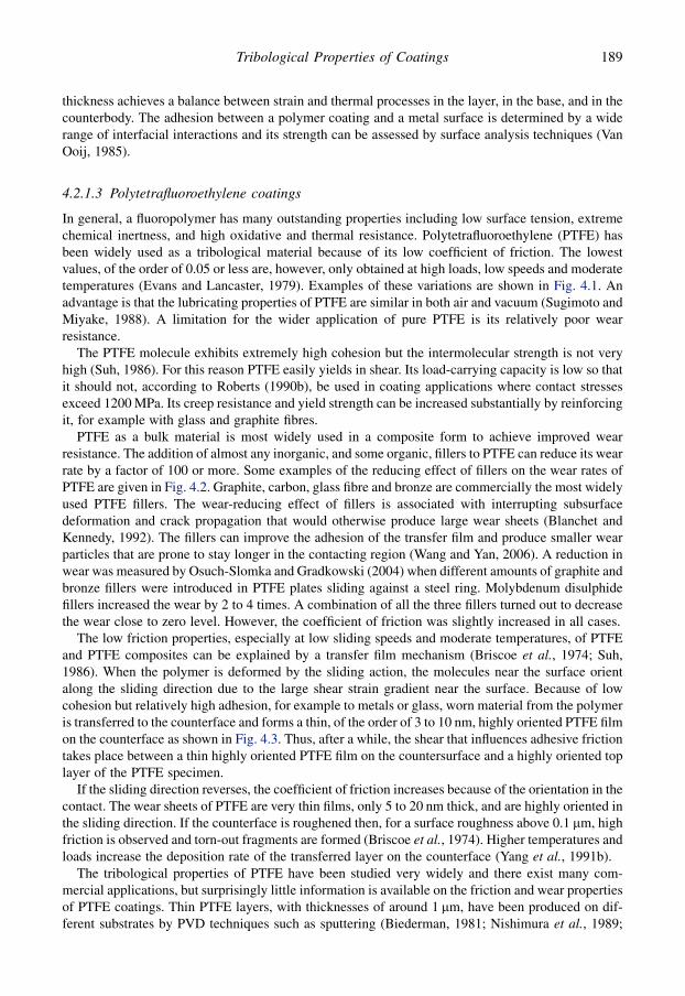
thickness achieves a balance between strain and thermal processes in the layer, in the base, and in thecounterbody. The adhesion between a polymer coating and a metal surface is determined by a widerange of interfacial interactions and its strength can be assessed by surface analysis techniques (VanOoij, 1985).
4.2.1.3 Polytetrafluoroethylene coatings
In general, a fluoropolymer has many outstanding properties including low surface tension, extremechemical inertness, and high oxidative and thermal resistance. Polytetrafluoroethylene (PTFE) hasbeen widely used as a tribological material because of its low coefficient of friction. The lowestvalues, of the order of 0.05 or less are, however, only obtained at high loads, low speeds and moderatetemperatures (Evans and Lancaster, 1979). Examples of these variations are shown in Fig. 4.1. Anadvantage is that the lubricating properties of PTFE are similar in both air and vacuum (Sugimoto andMiyake, 1988). A limitation for the wider application of pure PTFE is its relatively poor wearresistance.
The PTFE molecule exhibits extremely high cohesion but the intermolecular strength is not veryhigh (Suh, 1986). For this reason PTFE easily yields in shear. Its load-carrying capacity is low so thatit should not, according to Roberts (1990b), be used in coating applications where contact stressesexceed 1200 MPa. Its creep resistance and yield strength can be increased substantially by reinforcingit, for example with glass and graphite fibres.
PTFE as a bulk material is most widely used in a composite form to achieve improved wearresistance. The addition of almost any inorganic, and some organic, fillers to PTFE can reduce its wearrate by a factor of 100 or more. Some examples of the reducing effect of fillers on the wear rates ofPTFE are given in Fig. 4.2. Graphite, carbon, glass fibre and bronze are commercially the most widelyused PTFE fillers. The wear-reducing effect of fillers is associated with interrupting subsurfacedeformation and crack propagation that would otherwise produce large wear sheets (Blanchet andKennedy, 1992). The fillers can improve the adhesion of the transfer film and produce smaller wearparticles that are prone to stay longer in the contacting region (Wang and Yan, 2006). A reduction inwear was measured by Osuch-Slomka and Gradkowski (2004) when different amounts of graphite andbronze fillers were introduced in PTFE plates sliding against a steel ring. Molybdenum disulphidefillers increased the wear by 2 to 4 times. A combination of all the three fillers turned out to decreasethe wear close to zero level. However, the coefficient of friction was slightly increased in all cases.
The low friction properties, especially at low sliding speeds and moderate temperatures, of PTFEand PTFE composites can be explained by a transfer film mechanism (Briscoe et al., 1974; Suh,1986). When the polymer is deformed by the sliding action, the molecules near the surface orientalong the sliding direction due to the large shear strain gradient near the surface. Because of lowcohesion but relatively high adhesion, for example to metals or glass, worn material from the polymeris transferred to the counterface and forms a thin, of the order of 3 to 10 nm, highly oriented PTFE filmon the counterface as shown in Fig. 4.3. Thus, after a while, the shear that influences adhesive frictiontakes place between a thin highly oriented PTFE film on the countersurface and a highly oriented toplayer of the PTFE specimen.
If the sliding direction reverses, the coefficient of friction increases because of the orientation in thecontact. The wear sheets of PTFE are very thin films, only 5 to 20 nm thick, and are highly oriented inthe sliding direction. If the counterface is roughened then, for a surface roughness above 0.1 mm, highfriction is observed and torn-out fragments are formed (Briscoe et al., 1974). Higher temperatures andloads increase the deposition rate of the transferred layer on the counterface (Yang et al., 1991b).
The tribological properties of PTFE have been studied very widely and there exist many com-mercial applications, but surprisingly little information is available on the friction and wear propertiesof PTFE coatings. Thin PTFE layers, with thicknesses of around 1 mm, have been produced on dif-ferent substrates by PVD techniques such as sputtering (Biederman, 1981; Nishimura et al., 1989;
189Tribological Properties of Coatings
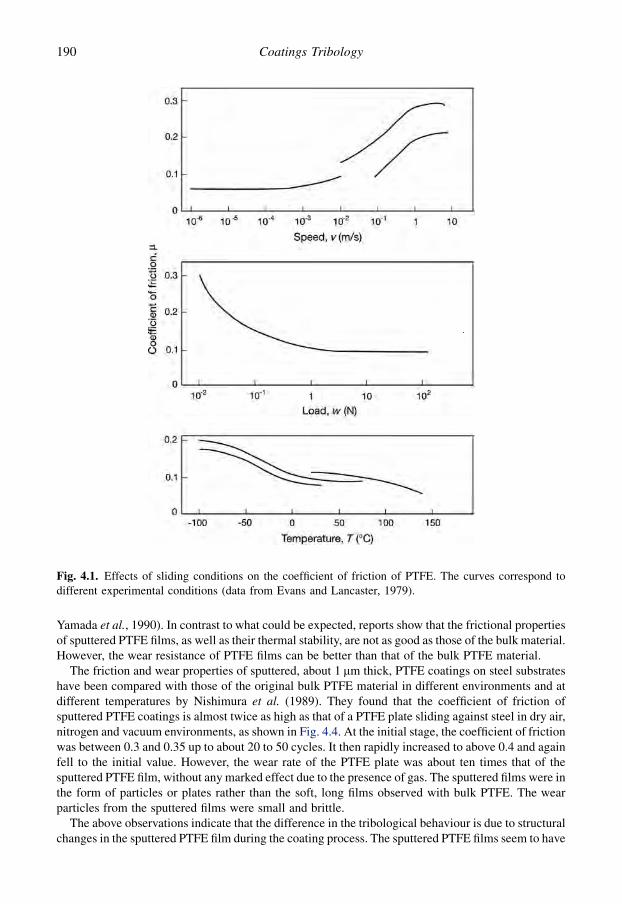
Yamada et al., 1990). In contrast to what could be expected, reports show that the frictional propertiesof sputtered PTFE films, as well as their thermal stability, are not as good as those of the bulk material.However, the wear resistance of PTFE films can be better than that of the bulk PTFE material.
The friction and wear properties of sputtered, about 1 mm thick, PTFE coatings on steel substrateshave been compared with those of the original bulk PTFE material in different environments and atdifferent temperatures by Nishimura et al. (1989). They found that the coefficient of friction ofsputtered PTFE coatings is almost twice as high as that of a PTFE plate sliding against steel in dry air,nitrogen and vacuum environments, as shown in Fig. 4.4. At the initial stage, the coefficient of frictionwas between 0.3 and 0.35 up to about 20 to 50 cycles. It then rapidly increased to above 0.4 and againfell to the initial value. However, the wear rate of the PTFE plate was about ten times that of thesputtered PTFE film, without any marked effect due to the presence of gas. The sputtered films were inthe form of particles or plates rather than the soft, long films observed with bulk PTFE. The wearparticles from the sputtered films were small and brittle.
The above observations indicate that the difference in the tribological behaviour is due to structuralchanges in the sputtered PTFE film during the coating process. The sputtered PTFE films seem to have
Fig. 4.1. Effects of sliding conditions on the coefficient of friction of PTFE. The curves correspond todifferent experimental conditions (data from Evans and Lancaster, 1979).
190 Coatings Tribology

an amorphous structure; they are harder, more brittle and more chemically active than the originalPTFE. The thermal stability of the sputtered PTFE was also considerably inferior to bulk PTFE. Thefilm began to evaporate gradually from about 60�C and its weight loss increased rapidly when thetemperature was over 240�C. The bulk PTFE, on the other hand, did not show signs of evaporationuntil the temperature exceeded 500�C. Nishimura et al. (1989) suggest that this indicates that thesputtered PTFE consists of particles having a lower molecular weight than that of the bulk PTFE.
In very slow speed sliding experiments with a steel ball sliding at a speed of 0.0004 m/s on a PTFEcoating rf sputtered on to a smooth glass substrate, Yamada et al. (1990) found no influence of loadwithin the range 0.5 to 10 N and no influence of coating thickness on the coefficient of friction withinthe range 0.05 to 1.0 mm. The coefficient of friction was initially 0.2 and then increased after some five
Fig. 4.2. Steady-state wear rates of PTFE composites sliding against smooth steel. The commerciallyavailable ones are marked with an asterisk (data from Evans and Lancaster, 1979).
Fig. 4.3. In a sliding PTFE on steel contact (a) thin PTFE wear sheets attach to the steel surface and(b) form, after a number of cycles, a complete PTFE transferred layer.
191Tribological Properties of Coatings

passes to 0.3 with a sapphire ball and slightly higher with a steel ball. This coefficient of friction issomewhat higher than that of the bulk polymer target. Yamada et al. believe that this is because thesurfaces of the deposited films exhibit higher surface energy than those of the target polymer.
The lifetime of sputtered PTFE and polyimide (PI) coatings on a glass substrate sliding againsta sapphire pin was observed in pin-on-disc experiments with a speed of 0.1 m/s and a load of 15 N byYamada et al. (1990). The PTFE film failed after 200 passes while PI failed after 4000 passes. It can beconcluded that the wear life of sputtered PTFE films seems to be poor, only 1/20 of that of PI films.The PTFE film was plastically deformed and wore away from the track with long film-like weardebris. The lifetime of the sputtered PTFE film could be increased by 3 to 6 times by heat treatment
Fig. 4.4. The coefficient of friction for an rf sputtered PTFE coating and a PTFE plate sliding on a steelsubstrate in pin-on-disc tests with a speed of 0.01 m/s and a load of 5 N in four different environments(data from Nishimura et al., 1989).
192 Coatings Tribology

at 200�C and 300�C, respectively. It was observed that the amount of oxygen in the films increasedafter heat treatment and this may increase the adhesion strength to the substrate and lead to a longerfilm life.
Efforts to improve the tribological and the dielectric properties of PTFE by developing a new kindof fluorine-containing thin film produced by rf sputtering using PTFE-perfluoropolyether (PFPE)grease as target material have been reported by Sugimoto and Miyake (1988). They measureda slightly reduced and more stable coefficient of friction down to 0.1 to 0.2 for a PTFE–PFPE filmcompared to 0.15 to 0.3 for the PTFE film in similar sliding conditions. However, as shown in Fig. 4.5there was almost no improvement in the wear life as measured by the number of cycles before thecoefficient of friction exceeded 0.3.
The addition of hard particles in the PTFE coating may have a beneficial influence on the wear andfriction properties mainly due to their hardening effect on the coating. This has been shown by Leeand Lim (2004) who added 1–4 weight% of nanocrystalline diamond particles composed of 4–6 nmsize crystalline diamond grains that had been produced by a detonation method. The thickness of thesprayed composite PTFE coating on an aluminium substrate was 30 mm. The best tribological per-formance was measured for the 2 weight% nanodiamond composite coatings in a reciprocating ball-on-plate wear tester with 0.8 N load and 0.01 m/s sliding speed against a 5.6 mm diameter ball-bearingsteel ball. In comparison with pure PTFE coatings the coefficient of friction decreased from 0.16 to0.08. Both the coefficient of friction and wear were reduced by about 50% as the ambient temperaturewas increased from room temperature to 150�C.
4.2.1.4 Polyimide coatings
Polyimides (PI) are a group of polymers that are used in tribological applications such as bearings andseals. They have coefficients of friction generally varying within the range of 0.1 to 0.6 depending oncomposition and additives (Suh, 1986; Fusaro, 1987a). They are interesting for use especially in spaceapplications because they have considerably lower coefficients of friction in vacuum, often less than0.1, and for some compositions, like 80% PMDA/20% BTDA polyimide, even as low as 0.02 ina vacuum of 0.13 Pa (Fusaro, 1987a).
The coefficient of friction for PI materials is temperature dependent and has a reversible transitionregion in dry air at 40� 10�C. Figure 4.6 shows how the coefficient of friction of bonded polyimide
Fig. 4.5. Variation in the coefficient of friction of 3 mm thick sputtered films, deposited on a stainless steelsubstrate, with number of sliding cycles under circumferential oscillatory sliding movement for (a) PTFEand (b) PTFE–PFPE films with a speed of 0.0015 m/s and a load of 5 N. B in air and C in vacuum (datafrom Sugimoto and Miyake, 1988).
193Tribological Properties of Coatings
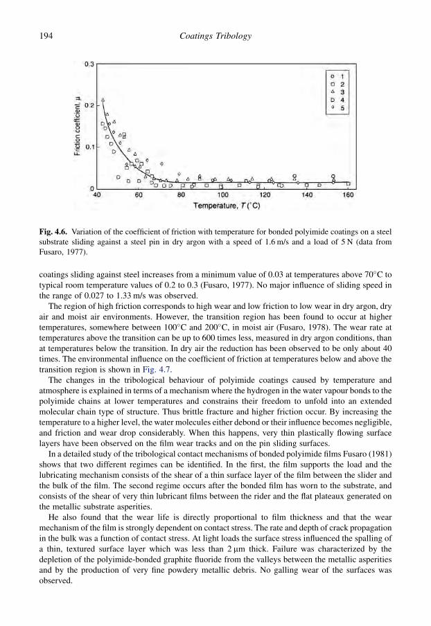
coatings sliding against steel increases from a minimum value of 0.03 at temperatures above 70�C totypical room temperature values of 0.2 to 0.3 (Fusaro, 1977). No major influence of sliding speed inthe range of 0.027 to 1.33 m/s was observed.
The region of high friction corresponds to high wear and low friction to low wear in dry argon, dryair and moist air environments. However, the transition region has been found to occur at highertemperatures, somewhere between 100�C and 200�C, in moist air (Fusaro, 1978). The wear rate attemperatures above the transition can be up to 600 times less, measured in dry argon conditions, thanat temperatures below the transition. In dry air the reduction has been observed to be only about 40times. The environmental influence on the coefficient of friction at temperatures below and above thetransition region is shown in Fig. 4.7.
The changes in the tribological behaviour of polyimide coatings caused by temperature andatmosphere is explained in terms of a mechanism where the hydrogen in the water vapour bonds to thepolyimide chains at lower temperatures and constrains their freedom to unfold into an extendedmolecular chain type of structure. Thus brittle fracture and higher friction occur. By increasing thetemperature to a higher level, the water molecules either debond or their influence becomes negligible,and friction and wear drop considerably. When this happens, very thin plastically flowing surfacelayers have been observed on the film wear tracks and on the pin sliding surfaces.
In a detailed study of the tribological contact mechanisms of bonded polyimide films Fusaro (1981)shows that two different regimes can be identified. In the first, the film supports the load and thelubricating mechanism consists of the shear of a thin surface layer of the film between the slider andthe bulk of the film. The second regime occurs after the bonded film has worn to the substrate, andconsists of the shear of very thin lubricant films between the rider and the flat plateaux generated onthe metallic substrate asperities.
He also found that the wear life is directly proportional to film thickness and that the wearmechanism of the film is strongly dependent on contact stress. The rate and depth of crack propagationin the bulk was a function of contact stress. At light loads the surface stress influenced the spalling ofa thin, textured surface layer which was less than 2 mm thick. Failure was characterized by thedepletion of the polyimide-bonded graphite fluoride from the valleys between the metallic asperitiesand by the production of very fine powdery metallic debris. No galling wear of the surfaces wasobserved.
Fig. 4.6. Variation of the coefficient of friction with temperature for bonded polyimide coatings on a steelsubstrate sliding against a steel pin in dry argon with a speed of 1.6 m/s and a load of 5 N (data fromFusaro, 1977).
194 Coatings Tribology
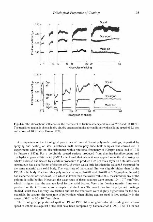
A comparison of the tribological properties of three different polyimide coatings, deposited byspraying and heating on steel substrates, with seven polyimide bulk samples was carried out inexperiments with a pin-on-disc tribometer with a rotational frequency of 100 rpm and a load of 10 Nby Fusaro (1987a). For a polyimide coated surface produced from diamine-hexafluoropane anddianhydride pyromellitic acid (PMDA) he found that when it was applied onto the disc using anartist’s airbrush and heated by a certain procedure to produce a 25 mm thick layer on a stainless steelsubstrate, it had a coefficient of friction of 0.45 which was a little less than the value 0.5 measured forthe same material as a solid body. The wear rate of the coated film was slightly higher than for thePMDA solid body. The two other polyimide coatings (PI-4701 and PI-4701þ 50% graphite fluoride)had a coefficient of friction of 0.15 which is lower than the lowest value, 0.2, measured for any of thepolyimide solid bodies. However, the wear rates of these coatings were around 10 $ 10�6 mm3/Nm,which is higher than the average level for the solid bodies. Very thin, flowing transfer films wereproduced on the 4.76 mm radius hemispherical steel pins. The conclusion for the polyimide coatingsstudied is that they had very low friction but that the wear rates were slightly higher than for the bulkmaterials. In vacuum the wear rate of polyimides when sliding against steel is low, typically in therange of 0.01 to 10 $ 10�6 mm3/Nm.
The tribological properties of sputtered PI and PTFE films on glass substrates sliding with a slowspeed of 0.0004 m/s against a steel ball have been compared by Yamada et al. (1990). The PI film had
Fig. 4.7. The atmospheric influence on the coefficient of friction at temperatures (a) 25�C and (b) 100�C.The transition region is shown in dry air, dry argon and moist air conditions with a sliding speed of 2.6 m/sand a load of 10 N (after Fusaro, 1978).
195Tribological Properties of Coatings

a coefficient of friction of 0.2, which was smaller than that for a PTFE film, which was 0.3, and it hada considerably more stable friction curve than the PTFE film. The coefficient of friction wasindependent of load in the range 0.5 to 10 N and independent of film thickness in the range 0.05 to1 mm. However, the friction of the PI film was somewhat higher than that for the target material asa solid body.
In the study of contact wear, Yamada et al. (1990) observed that the PI film was more brittle and hadhigher mechanical strength than a PTFE film. The wear lifetime of the PI film was about 4000 passes,which is about 20 times more than for the PTFE film. The longer life of the PI film, according toYamada et al., could be because very thin lubricant films of PI left on the track may exhibitintrinsically stronger adhesion to the substrate than PTFE. The replenishing effect of the PI film mayalso be responsible for the long life of the PI film, because a larger amount of wear debris of the PIfilm was supplied to the track as a result of the film wear at both sides of the track. In contrast tothe PTFE film, no increase in wear lifetime for the PI film was observed after heat treatment at 200�Cand 300�C.
4.2.1.5 Elastomeric coatings
The characteristic feature of elastomers is their ability to recover from large deformations. The elasticmodulus of rubber is extremely small. The elastic deformation of rubber can be up to 1000% and isonly 1% for many polymer materials and less than 1% for ordinary metals. The coefficient of frictionof rubber is generally high when sliding in dry conditions on other solid materials. Hysteresis phe-nomena may play an important role in their frictional behaviour. Stick–slip occurs often but there is nosingle value for the static coefficient of friction as it depends upon the initial dwell time and the rate ofstarting velocity (Persson et al., 2003). Elastomers have a good erosive and abrasive wear resistancebecause of their ability to deform elastically (Moore, 1975; SiWei, 2000).
The geometry of a contact on a macroscale also affects the hysteresis friction. When a ball slides ona plane surface covered by an elastomeric coating, the coating continuously deforms elastically andrecovers after the contact adding a hysteresis component to the friction. A raised lip is formed in frontof the ball. In the opposite situation, when the ball is covered by the coating, the hysteresis friction isminor because there is no continuous elastic deformation and recovery as shown in Fig. 4.8.
The behaviour of elastomeric coatings of different hardnesses and with thicknesses of 4 mm and500 mm on glass substrates sliding against a glass hemispherical indenter or ceramic cones withdifferent angles at a low speed of only 0.0002 m/s and loads in the range of 0.01 to 0.5 N was studiedby Adams et al. (1990). They measured a coefficient of friction of 0.31 to 0.45 with a 4.93 mm radiusindenter sliding on the thin elastomer film at low loads of 0.01 N and no detectable sliding damagewas produced. In thick film experiments with a low load, the ceramic cone gave a coefficient offriction of 0.5 to 1 when sliding on a hard coating and 1.5 to 4 when sliding on a soft coating, withoutany observation of stick–slip. At a higher normal load of 1 N there was a gross stick–slip response.The coefficient of friction was about 0.55 for the harder coating and 0.9 for the soft coating. Adams
Fig. 4.8. Hysteresis friction occurs (a) continuously when the plane surface is covered by an elastomericcoating and (b) only in the load and unload positions when the ball is coated.
196 Coatings Tribology

et al. conclude that for low normal loads the non-adhesive component of the coefficient of frictionvaries with the tangent of the cone angle. The results discriminate between soft coatings with highfracture toughness and hard coatings with low fracture toughness. For higher normal loads the am-plitude of the stick phases in the observed stick–slip behaviour decreases with increasing hardness ofthe coating due to the reduction in fracture toughness. The nature of the damage was analogous to thatobserved for bulk elastomer specimens.
For coating thicknesses less than 0.2 mm the friction is considered to be independent of thethickness (Adams et al., 1990). This can be explained by the effect of material build-up around thesphere, outside the Hertzian contact area, which has to be under sufficient pressure before it makesa significant contribution to the frictional traction.
In reciprocating friction experiments with cylinders coated with a 300 mm thick silicone rubberlayer sliding on a glass plate with mineral oil lubrication at speeds of 0.01 to 0.15 m/s and loads of42 to 77 N, Gladstone (1988) measured very low peak values for the coefficient of friction in the rangeof 0.01 to 0.03. The favourable effect of an elastomeric layer in creating elastohydrodynamic lu-brication conditions has been shown by Hooke (1986). He developed a method to determine theclearance in lubricated elastomeric layer contacts.
4.2.2 Soft metal coatings
Soft metals like lead, silver, gold, copper, nickel and indium can provide the low shear conditionsoften needed for good frictional properties of coated surfaces; but this is not enough. Several otherparameters also need to be optimized, such as adhesion to the substrate, film thickness, surfaceroughness, load and sliding speed.
Bowden and Tabor (1950) studied the behaviour of several soft metal films and found that lowvalues for the coefficient of friction, even less than 0.1, can be obtained with coatings in the thicknessrange of 0.1 to 10 mm, sliding against a metal counterface. However, the wear and lifetime of suchfilms was often a problem. The vacuum deposition methods and especially ion plating developed inthe 1960s and 1970s provided a new method to deposit homogeneous metal films with improvedadhesion to the substrate.
It was earlier assumed that the metal layer softens during sliding and acts as a lubricant. Thisexplanation may well be correct at high sliding speeds and normal loads when high localized tem-peratures are produced by the flash heating effects. However, Jahanmir et al. (1976) showed that it isnot the absolute softness of the coating which is important. It is the ratio of shear stresses between thesubstrate and the coating which is the determining factor. To support this they demonstrated that evena reasonably high melting point metal such as nickel can be effective in wear reduction under low-speed sliding, and that the thickness of the coating has a pronounced influence.
The film thickness, the surface roughness and the environmental influence on the oxidation of thecoating are important parameters in applications with thin metal films. We have earlier mentioned(Fig. 3.76) that the coefficient of friction reaches a minimum value for lead films deposited on steelsliding against a steel counterface at a thickness of about 0.5 mm while friction is higher for boththinner and thicker films. Very thin films suffer from asperity breakthrough while thicker films resultin a larger contact area and thus higher friction.
It is interesting that thinner films can produce lower wear rates than thick films (Sherbiney andHalling, 1977). With thick films the wear mechanism is essentially microcutting of the coating by themating surface asperities. For thin films the wear is based on a fatigue mechanism, with the matingsurface asperities breaking through the film and contacting the substrate material.
It appears that there exists an optimum film thickness for soft metal coatings. Jahanmir et al. (1976)showed that this is in general less than 1 mm for steel coated with metals like Cd, Ag, Au and Ni. Theygive a theoretical explanation based on the delamination wear theory. A thin layer of a soft metalcoated on a hard substrate can retard the wear of the harder substrate by preventing plastic
197Tribological Properties of Coatings
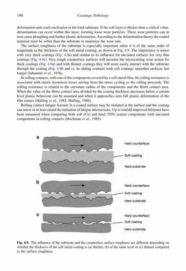
deformation and crack nucleation in the hard substrate. If the soft layer is thicker than a critical value,delamination can occur within this layer, forming loose wear particles. These wear particles can inturn cause ploughing and further plastic deformation. According to the delamination theory the coatedmaterial must be softer than the substrate to minimize the wear rate.
The surface roughness of the substrate is especially important when it is of the same order ofmagnitude as the thickness of the soft metal coating, as shown in Fig. 4.9. The importance is minorwith very thick coatings (Fig. 4.9a) and similar to its influence for uncoated surfaces for very thincoatings (Fig. 4.9c). Very rough counterface surfaces will increase the microcutting wear action forthick coatings (Fig. 4.9a) and with thinner coatings they will more easily interact with the substratethrough the coating (Fig. 4.9b and c). In sliding contacts with soft coatings smoother surfaces lastlonger (Jahanmir et al., 1976).
In rolling contacts, with one of the components covered by a soft metal film, the rolling resistance isassociated with elastic hysteresis losses arising from the stress cycling as the rolling proceeds. Therolling resistance is related to the curvature radius of the components and the Hertz contact area.When the value of the Hertz contact area divided by the coating thickness decreases below a certainlevel plastic behaviour can be assumed and when it approaches zero full plastic deformation of thefilm ensues (Halling et al., 1985; Halling, 1986).
Rolling contact fatigue fracture in a coated surface may be initiated at the surface and the coatingcan arrest or at least retard the initiation of fatigue microcracks. Up to tenfold improved lifetimes havebeen measured when comparing both soft (Cu) and hard (TiN) coated components with uncoatedcomponents in rolling contacts (Hochman et al., 1985).
Fig. 4.9. The influence of the substrate and the counterface surface roughness are different depending onwhether the thickness of the soft metal coating is (a) thicker, (b) of the same level or (c) thinner comparedto the surface roughness.
198 Coatings Tribology
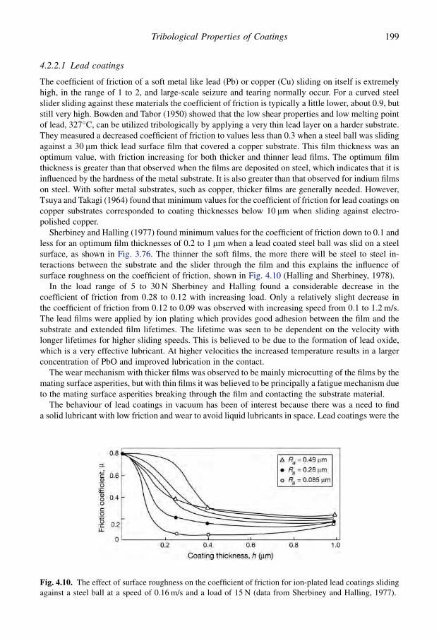
4.2.2.1 Lead coatings
The coefficient of friction of a soft metal like lead (Pb) or copper (Cu) sliding on itself is extremelyhigh, in the range of 1 to 2, and large-scale seizure and tearing normally occur. For a curved steelslider sliding against these materials the coefficient of friction is typically a little lower, about 0.9, butstill very high. Bowden and Tabor (1950) showed that the low shear properties and low melting pointof lead, 327�C, can be utilized tribologically by applying a very thin lead layer on a harder substrate.They measured a decreased coefficient of friction to values less than 0.3 when a steel ball was slidingagainst a 30 mm thick lead surface film that covered a copper substrate. This film thickness was anoptimum value, with friction increasing for both thicker and thinner lead films. The optimum filmthickness is greater than that observed when the films are deposited on steel, which indicates that it isinfluenced by the hardness of the metal substrate. It is also greater than that observed for indium filmson steel. With softer metal substrates, such as copper, thicker films are generally needed. However,Tsuya and Takagi (1964) found that minimum values for the coefficient of friction for lead coatings oncopper substrates corresponded to coating thicknesses below 10 mm when sliding against electro-polished copper.
Sherbiney and Halling (1977) found minimum values for the coefficient of friction down to 0.1 andless for an optimum film thicknesses of 0.2 to 1 mm when a lead coated steel ball was slid on a steelsurface, as shown in Fig. 3.76. The thinner the soft films, the more there will be steel to steel in-teractions between the substrate and the slider through the film and this explains the influence ofsurface roughness on the coefficient of friction, shown in Fig. 4.10 (Halling and Sherbiney, 1978).
In the load range of 5 to 30 N Sherbiney and Halling found a considerable decrease in thecoefficient of friction from 0.28 to 0.12 with increasing load. Only a relatively slight decrease inthe coefficient of friction from 0.12 to 0.09 was observed with increasing speed from 0.1 to 1.2 m/s.The lead films were applied by ion plating which provides good adhesion between the film and thesubstrate and extended film lifetimes. The lifetime was seen to be dependent on the velocity withlonger lifetimes for higher sliding speeds. This is believed to be due to the formation of lead oxide,which is a very effective lubricant. At higher velocities the increased temperature results in a largerconcentration of PbO and improved lubrication in the contact.
The wear mechanism with thicker films was observed to be mainly microcutting of the films by themating surface asperities, but with thin films it was believed to be principally a fatigue mechanism dueto the mating surface asperities breaking through the film and contacting the substrate material.
The behaviour of lead coatings in vacuum has been of interest because there was a need to finda solid lubricant with low friction and wear to avoid liquid lubricants in space. Lead coatings were the
Fig. 4.10. The effect of surface roughness on the coefficient of friction for ion-plated lead coatings slidingagainst a steel ball at a speed of 0.16 m/s and a load of 15 N (data from Sherbiney and Halling, 1977).
199Tribological Properties of Coatings
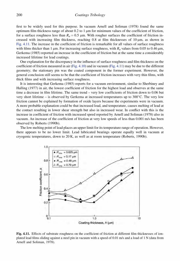
first to be widely used for this purpose. In vacuum Arnell and Soliman (1978) found the sameoptimum film thickness range of about 0.2 to 1 mm for minimum values of the coefficient of friction,for a surface roughness less than Ra¼ 0.5 mm. With rougher surfaces the coefficient of friction in-creased with increasing film thickness, reaching 0.8 at film thicknesses of 10 mm, as shown inFig. 4.11. The increase in the coefficient of friction is remarkable for all values of surface roughnesswith films thicker than 1 mm. For increasing surface roughness, with Ra values from 0.05 to 0.46 mm,Gerkema (1985) reported an increase in the coefficient of friction but at the same time a considerablyincreased lifetime for lead coatings.
One explanation for the discrepancy in the influence of surface roughness and film thickness on thecoefficient of friction measured in air (Fig. 4.10) and in vacuum (Fig. 4.11) may be due to the differentgeometry; the stationary pin was the coated component in the former experiment. However, thegeneral conclusion still seems to be that the coefficient of friction increases with very thin films, withthick films and with increasing surface roughness.
It is interesting that Gerkema (1985) reports for a vacuum environment, similar to Sherbiney andHalling (1977) in air, the lowest coefficient of friction for the highest load and observes at the sametime a decrease in film lifetime. The same trend – very low coefficients of friction down to 0.06 butvery short lifetime – is observed by Gerkema at increased temperatures up to 300�C. The very lowfriction cannot be explained by formation of oxide layers because the experiments were in vacuum.A more probable explanation could be that increased load, and temperature, causes melting of lead atthe contact resulting in lower shear strength but also in increased wear. In conflict with this is theincrease in coefficient of friction with increased speed reported by Arnell and Soliman (1978) also invacuum. An increase of the coefficient of friction at very low speeds of less than 0.001 m/s has beenobserved by Roberts (1990b).
The low melting point of lead places an upper limit for its temperature range of operation. However,there appears to be no lower limit. Lead lubricated bearings operate equally well in vacuum atcryogenic temperatures, down to 20 K, as well as at room temperature (Roberts, 1990b).
Fig. 4.11. Effects of substrate roughness on the coefficient of friction at different film thicknesses of ion-plated lead films sliding against a steel pin in vacuum with a speed of 0.01 m/s and a load of 1 N (data fromArnell and Soliman, 1978).
200 Coatings Tribology
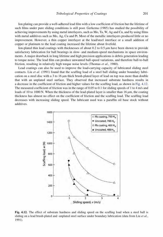
Ion plating can provide a well-adhered lead film with a low coefficient of friction but the lifetime ofsuch films under pure sliding conditions is still poor. Gerkema (1985) has studied the possibility ofachieving improvements by using metal interlayers, such as Mo, Ta, W, Ag and Cu, and by using filmswith metal additives such as Mo, Ag, Cu and Pt. Most of the metallic interlayers produced little or noimprovement. However, a thin copper interlayer at the lead/steel interface or a small addition ofcopper or platinum to the lead coating increased the lifetime about fivefold.
Ion-plated thin lead coatings with thicknesses of about 0.2 to 0.5 mm have been shown to providesatisfactory lubrication for ball bearings in slow- and medium-speed mechanisms in space environ-ments. A major drawback in long lifetime and high precision applications is debris generation leadingto torque noise. The lead film can produce unwanted ball-speed variations, and therefore ball-to-ballfriction, resulting in relatively high torque noise levels (Thomas et al., 1980).
Lead coatings can also be used to improve the load-carrying capacity of lubricated sliding steelcontacts. Liu et al. (1991) found that the scuffing load of a steel ball sliding under boundary lubri-cation on a steel disc with a 3 to 16 mm thick brush-plated layer of lead on top was more than doublethat with an unplated steel surface. They observed that increased substrate hardness results ina decrease in the coefficient of friction and higher values for the scuffing load, as shown in Fig. 4.12.The measured coefficient of friction was in the range of 0.05 to 0.1 for sliding speeds of 1 to 4 m/s andloads of 10 to 1000 N. When the thickness of the lead-plated layer is smaller than 16 mm, the coatingthickness has almost no effect on the coefficient of friction and the scuffing load. The scuffing loaddecreases with increasing sliding speed. The lubricant used was a paraffin oil base stock withoutadditives.
Fig. 4.12. The effect of substrate hardness and sliding speed on the scuffing load when a steel ball issliding on a lead brush-plated and -unplated steel surface under boundary lubrication (data from Liu et al.,1991).
201Tribological Properties of Coatings
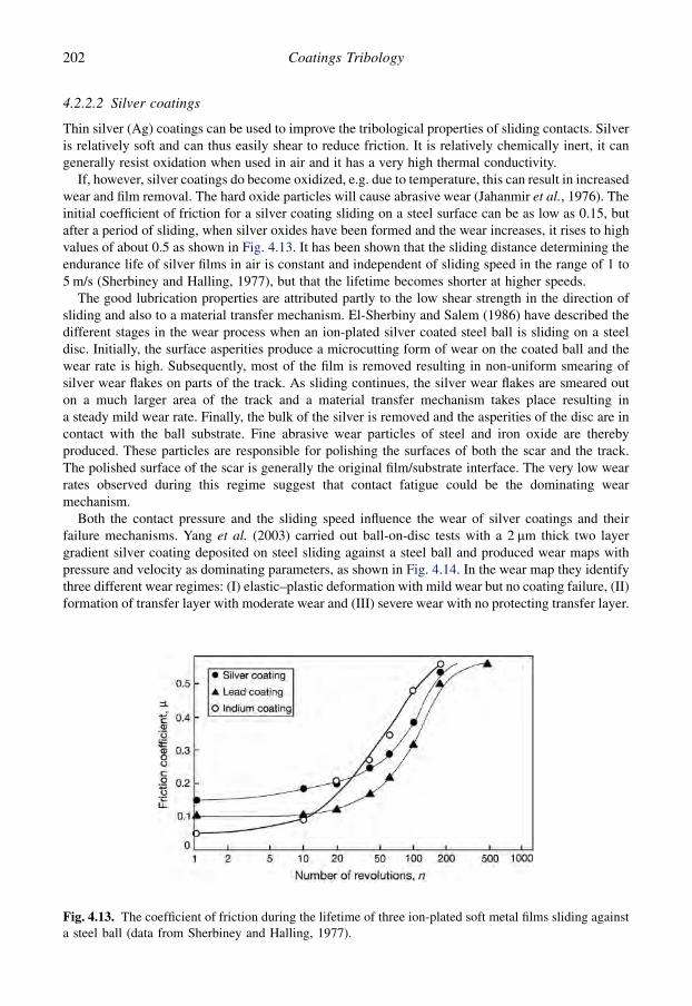
4.2.2.2 Silver coatings
Thin silver (Ag) coatings can be used to improve the tribological properties of sliding contacts. Silveris relatively soft and can thus easily shear to reduce friction. It is relatively chemically inert, it cangenerally resist oxidation when used in air and it has a very high thermal conductivity.
If, however, silver coatings do become oxidized, e.g. due to temperature, this can result in increasedwear and film removal. The hard oxide particles will cause abrasive wear (Jahanmir et al., 1976). Theinitial coefficient of friction for a silver coating sliding on a steel surface can be as low as 0.15, butafter a period of sliding, when silver oxides have been formed and the wear increases, it rises to highvalues of about 0.5 as shown in Fig. 4.13. It has been shown that the sliding distance determining theendurance life of silver films in air is constant and independent of sliding speed in the range of 1 to5 m/s (Sherbiney and Halling, 1977), but that the lifetime becomes shorter at higher speeds.
The good lubrication properties are attributed partly to the low shear strength in the direction ofsliding and also to a material transfer mechanism. El-Sherbiny and Salem (1986) have described thedifferent stages in the wear process when an ion-plated silver coated steel ball is sliding on a steeldisc. Initially, the surface asperities produce a microcutting form of wear on the coated ball and thewear rate is high. Subsequently, most of the film is removed resulting in non-uniform smearing ofsilver wear flakes on parts of the track. As sliding continues, the silver wear flakes are smeared outon a much larger area of the track and a material transfer mechanism takes place resulting ina steady mild wear rate. Finally, the bulk of the silver is removed and the asperities of the disc are incontact with the ball substrate. Fine abrasive wear particles of steel and iron oxide are therebyproduced. These particles are responsible for polishing the surfaces of both the scar and the track.The polished surface of the scar is generally the original film/substrate interface. The very low wearrates observed during this regime suggest that contact fatigue could be the dominating wearmechanism.
Both the contact pressure and the sliding speed influence the wear of silver coatings and theirfailure mechanisms. Yang et al. (2003) carried out ball-on-disc tests with a 2 mm thick two layergradient silver coating deposited on steel sliding against a steel ball and produced wear maps withpressure and velocity as dominating parameters, as shown in Fig. 4.14. In the wear map they identifythree different wear regimes: (I) elastic–plastic deformation with mild wear but no coating failure, (II)formation of transfer layer with moderate wear and (III) severe wear with no protecting transfer layer.
Fig. 4.13. The coefficient of friction during the lifetime of three ion-plated soft metal films sliding againsta steel ball (data from Sherbiney and Halling, 1977).
202 Coatings Tribology
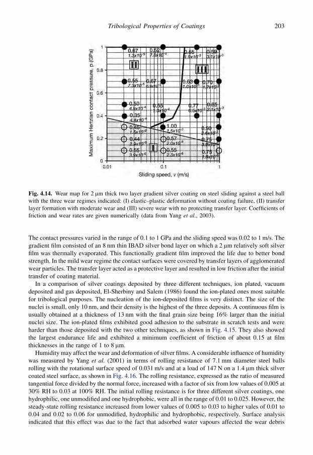
The contact pressures varied in the range of 0.1 to 1 GPa and the sliding speed was 0.02 to 1 m/s. Thegradient film consisted of an 8 nm thin IBAD silver bond layer on which a 2 mm relatively soft silverfilm was thermally evaporated. This functionally gradient film improved the life due to better bondstrength. In the mild wear regime the contact surfaces were covered by transfer layers of agglomeratedwear particles. The transfer layer acted as a protective layer and resulted in low friction after the initialtransfer of coating material.
In a comparison of silver coatings deposited by three different techniques, ion plated, vacuumdeposited and gas deposited, El-Sherbiny and Salem (1986) found the ion-plated ones most suitablefor tribological purposes. The nucleation of the ion-deposited films is very distinct. The size of thenuclei is small, only 10 nm, and their density is the highest of the three deposits. A continuous film isusually obtained at a thickness of 13 nm with the final grain size being 16% larger than the initialnuclei size. The ion-plated films exhibited good adhesion to the substrate in scratch tests and wereharder than those deposited with the two other techniques, as shown in Fig. 4.15. They also showedthe largest endurance life and exhibited a minimum coefficient of friction of about 0.15 at filmthicknesses in the range of 1 to 8 mm.
Humidity may affect the wear and deformation of silver films. A considerable influence of humiditywas measured by Yang et al. (2001) in terms of rolling resistance of 7.1 mm diameter steel ballsrolling with the rotational surface speed of 0.031 m/s and at a load of 147 N on a 1.4 mm thick silvercoated steel surface, as shown in Fig. 4.16. The rolling resistance, expressed as the ratio of measuredtangential force divided by the normal force, increased with a factor of six from low values of 0.005 at30% RH to 0.03 at 100% RH. The initial rolling resistance is for three different silver coatings, onehydrophilic, one unmodified and one hydrophobic, were all in the range of 0.01 to 0.025. However, thesteady-state rolling resistance increased from lower values of 0.005 to 0.03 to higher vales of 0.01 to0.04 and 0.02 to 0.06 for unmodified, hydrophilic and hydrophobic, respectively. Surface analysisindicated that this effect was due to the fact that adsorbed water vapours affected the wear debris
Fig. 4.14. Wear map for 2 mm thick two layer gradient silver coating on steel sliding against a steel ballwith the three wear regimes indicated: (I) elastic–plastic deformation without coating failure, (II) transferlayer formation with moderate wear and (III) severe wear with no protecting transfer layer. Coefficients offriction and wear rates are given numerically (data from Yang et al., 2003).
203Tribological Properties of Coatings
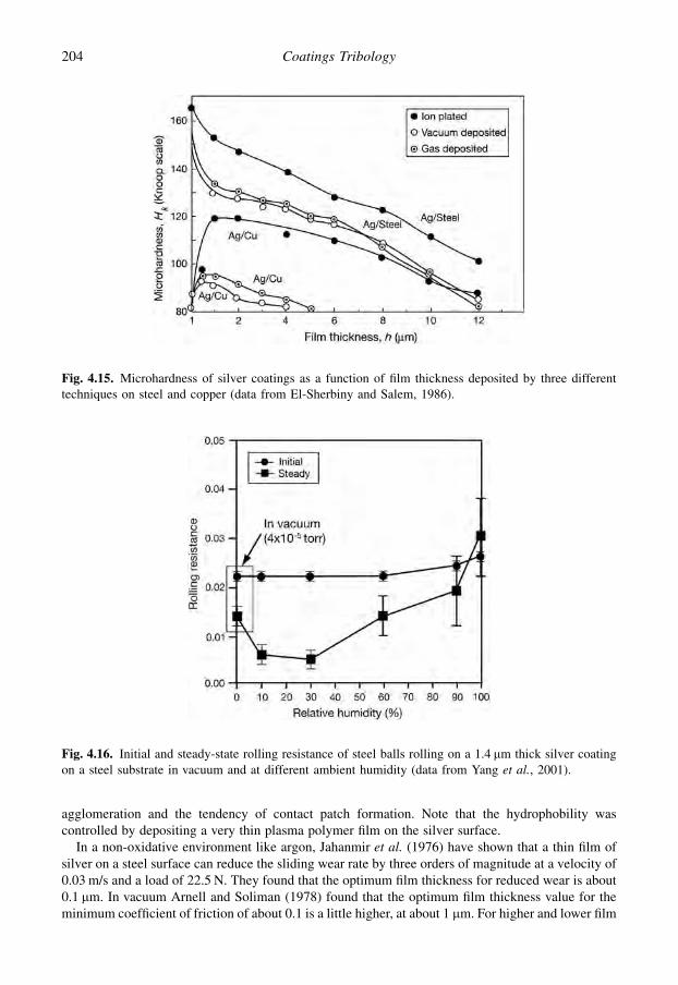
agglomeration and the tendency of contact patch formation. Note that the hydrophobility wascontrolled by depositing a very thin plasma polymer film on the silver surface.
In a non-oxidative environment like argon, Jahanmir et al. (1976) have shown that a thin film ofsilver on a steel surface can reduce the sliding wear rate by three orders of magnitude at a velocity of0.03 m/s and a load of 22.5 N. They found that the optimum film thickness for reduced wear is about0.1 mm. In vacuum Arnell and Soliman (1978) found that the optimum film thickness value for theminimum coefficient of friction of about 0.1 is a little higher, at about 1 mm. For higher and lower film
Fig. 4.15. Microhardness of silver coatings as a function of film thickness deposited by three differenttechniques on steel and copper (data from El-Sherbiny and Salem, 1986).
Fig. 4.16. Initial and steady-state rolling resistance of steel balls rolling on a 1.4 mm thick silver coatingon a steel substrate in vacuum and at different ambient humidity (data from Yang et al., 2001).
204 Coatings Tribology
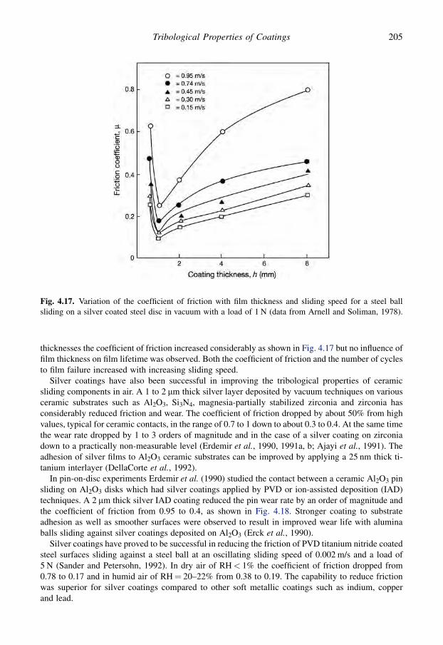
thicknesses the coefficient of friction increased considerably as shown in Fig. 4.17 but no influence offilm thickness on film lifetime was observed. Both the coefficient of friction and the number of cyclesto film failure increased with increasing sliding speed.
Silver coatings have also been successful in improving the tribological properties of ceramicsliding components in air. A 1 to 2 mm thick silver layer deposited by vacuum techniques on variousceramic substrates such as Al2O3, Si3N4, magnesia-partially stabilized zirconia and zirconia hasconsiderably reduced friction and wear. The coefficient of friction dropped by about 50% from highvalues, typical for ceramic contacts, in the range of 0.7 to 1 down to about 0.3 to 0.4. At the same timethe wear rate dropped by 1 to 3 orders of magnitude and in the case of a silver coating on zirconiadown to a practically non-measurable level (Erdemir et al., 1990, 1991a, b; Ajayi et al., 1991). Theadhesion of silver films to Al2O3 ceramic substrates can be improved by applying a 25 nm thick ti-tanium interlayer (DellaCorte et al., 1992).
In pin-on-disc experiments Erdemir et al. (1990) studied the contact between a ceramic Al2O3 pinsliding on Al2O3 disks which had silver coatings applied by PVD or ion-assisted deposition (IAD)techniques. A 2 mm thick silver IAD coating reduced the pin wear rate by an order of magnitude andthe coefficient of friction from 0.95 to 0.4, as shown in Fig. 4.18. Stronger coating to substrateadhesion as well as smoother surfaces were observed to result in improved wear life with aluminaballs sliding against silver coatings deposited on Al2O3 (Erck et al., 1990).
Silver coatings have proved to be successful in reducing the friction of PVD titanium nitride coatedsteel surfaces sliding against a steel ball at an oscillating sliding speed of 0.002 m/s and a load of5 N (Sander and Petersohn, 1992). In dry air of RH< 1% the coefficient of friction dropped from0.78 to 0.17 and in humid air of RH¼ 20–22% from 0.38 to 0.19. The capability to reduce frictionwas superior for silver coatings compared to other soft metallic coatings such as indium, copperand lead.
Fig. 4.17. Variation of the coefficient of friction with film thickness and sliding speed for a steel ballsliding on a silver coated steel disc in vacuum with a load of 1 N (data from Arnell and Soliman, 1978).
205Tribological Properties of Coatings
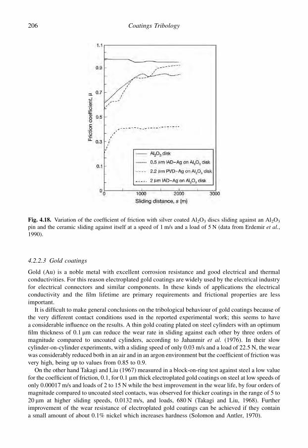
4.2.2.3 Gold coatings
Gold (Au) is a noble metal with excellent corrosion resistance and good electrical and thermalconductivities. For this reason electroplated gold coatings are widely used by the electrical industryfor electrical connectors and similar components. In these kinds of applications the electricalconductivity and the film lifetime are primary requirements and frictional properties are lessimportant.
It is difficult to make general conclusions on the tribological behaviour of gold coatings because ofthe very different contact conditions used in the reported experimental work; this seems to havea considerable influence on the results. A thin gold coating plated on steel cylinders with an optimumfilm thickness of 0.1 mm can reduce the wear rate in sliding against each other by three orders ofmagnitude compared to uncoated cylinders, according to Jahanmir et al. (1976). In their slowcylinder-on-cylinder experiments, with a sliding speed of only 0.03 m/s and a load of 22.5 N, the wearwas considerably reduced both in an air and in an argon environment but the coefficient of friction wasvery high, being up to values from 0.85 to 0.9.
On the other hand Takagi and Liu (1967) measured in a block-on-ring test against steel a low valuefor the coefficient of friction, 0.1, for 0.1 mm thick electroplated gold coatings on steel at low speeds ofonly 0.00017 m/s and loads of 2 to 15 N while the best improvement in the wear life, by four orders ofmagnitude compared to uncoated steel contacts, was observed for thicker coatings in the range of 5 to20 mm at higher sliding speeds, 0.0132 m/s, and loads, 680 N (Takagi and Liu, 1968). Furtherimprovement of the wear resistance of electroplated gold coatings can be achieved if they containa small amount of about 0.1% nickel which increases hardness (Solomon and Antler, 1970).
Fig. 4.18. Variation of the coefficient of friction with silver coated Al2O3 discs sliding against an Al2O3
pin and the ceramic sliding against itself at a speed of 1 m/s and a load of 5 N (data from Erdemir et al.,1990).
206 Coatings Tribology

The tribological mechanisms of a gold coating sliding against itself have been studied in detail byTian et al. (1991b). For the purpose of improving electrical connectors they measured friction andwear in a slowly reciprocating contact with a 1.5 mm thick electroplated gold layer on a 2.5 mm nickelinterlayer on a brass substrate. The coefficient of friction had an initial value of 0.3 which thenincreased through three stages reaching a maximum value of 1.2 as shown in Fig. 4.19. The initiallinear increase in the coefficient of friction may be due to an increase in the contact area by wear andthus an increased area for adhesion. Lubrication with polyphenyl ether decreased the coefficient offriction down to 0.1.
Tian et al. (1991b) present the following description of how the contact mechanism changes duringthe history of the contact. They distinguish between three different stages as illustrated in Fig. 4.20.In stage 1, a prow forms in front of the slider due to strong adhesion between the gold surfaces(Fig. 4.20a). The wear of the gold film is marginal at this stage. During sliding in stage 2, cracks areinitiated and propagate at the nickel/brass interface owing to the large interfacial shear stress. Theycontinue to propagate along the interface and finally emerge at the surface, resulting in thin plate-like wear particles (Fig. 4.20b). These are broken into pieces and adhere to the film surface. By thistime the electroplated system has technically failed because the exposure of the substrate will soonlead to severe corrosion, resulting in an unacceptable increase in contact resistance. As the slidingenters into stage 3, wear particles are continually delaminated from the nickel/brass interface ofthe ball specimen (Fig. 4.20c). The damage zone is enlarged and steady wear of the brass substratetakes place.
Another detailed analysis of the same contacting system but in dry and lubricated fretting condi-tions with different frequencies and amplitudes was reported by Tian et al. (1991a). The coefficient offriction was independent of the fretting amplitude.
Co-sputtering of molybdenum disulphide with gold can improve the tribological properties of goldcoatings considerably. Lince (2004) tested co-sputtered Au/MoS2 coatings with MoS2 content from0 to 100% deposited on steel plates in a pin-on-disc tribometer at 5 N load and 0.08 m/s sliding speedsliding against a steel ball and pin in nitrogen gas. The film with 95 at.% Au and pure Au failed afterless than 10 m of sliding. However, a 15 at.% of MoS2 content resulted in good endurance life at thelower contact pressure of 0.1 MPa and the friction dropped to 0.03 for both low and high (730 MPa)contact pressures. Good endurance life was reached at high contact pressure at a MoS2 content of 41at.% and then the coefficient of friction was as low as 0.013. At low contact stress the lubrication wasprovided by a thin, about 1 nm thick, film of relatively pure MoS2 regardless of the contact stress.
Fig. 4.19. The coefficient of friction as a function of sliding cycles for an electroplated gold coating inreciprocating sliding on itself with a speed of 0.004 m/s and a load of 1 N (after Tian et al., 1991b).
207Tribological Properties of Coatings

4.2.2.4 Indium coatings
Bowden and Tabor (1950) used indium (In) when they studied the tribological mechanisms of thin andsoft metal coatings in their pioneering work. Indium is a soft metal that oxidizes relatively slowly.They found that minimum values for the coefficient of friction down to 0.08 could be obtained byusing optimum film thicknesses of 0.1 to 1 mm. This was later confirmed both in air by Sherbiney andHalling (1977) and in vacuum by Arnell and Soliman (1978). The influence of film thickness on filmlifetime was only minor in vacuum.
The initial coefficient of friction for a steel ball sliding on an indium coated steel disc was found tobe only 0.05 by Sherbiney and Halling (1977) as shown in Fig. 4.13. However, after some 20 revo-lutions the indium changed from being shiny metallic to a greyish colour and the coefficient of frictionthen increased to more than 0.5, followed by film breakdown.
Sherbiney and Halling also found that the coefficient of friction decreases with increasing loadwhen an indium coated steel ball slides on a steel surface, but variations in speed within the range0.1 to 1.2 m/s have almost no effect at all. Increased speed resulted, however, in a shorter film lifetimeand a shorter effective sliding distance before failure. In vacuum, Arnell and Soliman observed thatboth the coefficient of friction and the wear increase with increased sliding speed.
4.2.2.5 Nickel coatings
Nickel (Ni) coatings deposited by electroplating and with a thickness of 40 mm have good corrosionresistance but poor wear resistance, e.g. compared to conventional chromium-plated coatings. The
Fig. 4.20. The contact mechanism of an electroplated gold coated ball with a nickel interlayer and a brasssubstrate in reciprocating sliding on a plate with the same surface coating, showing changes during thehistory of the contact (after Tian et al., 1991b).
208 Coatings Tribology
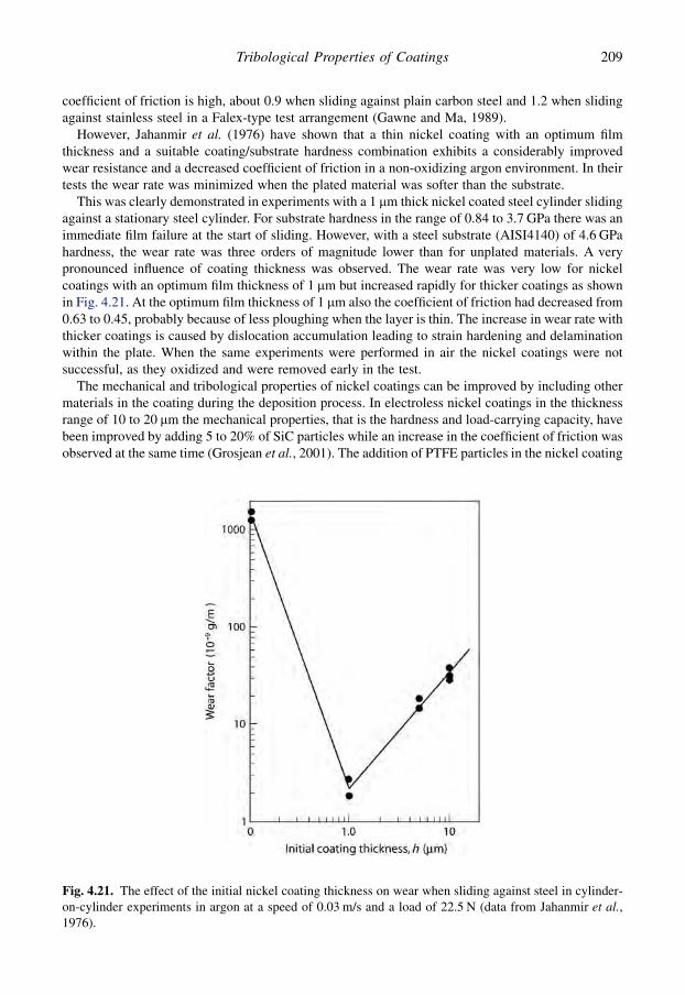
coefficient of friction is high, about 0.9 when sliding against plain carbon steel and 1.2 when slidingagainst stainless steel in a Falex-type test arrangement (Gawne and Ma, 1989).
However, Jahanmir et al. (1976) have shown that a thin nickel coating with an optimum filmthickness and a suitable coating/substrate hardness combination exhibits a considerably improvedwear resistance and a decreased coefficient of friction in a non-oxidizing argon environment. In theirtests the wear rate was minimized when the plated material was softer than the substrate.
This was clearly demonstrated in experiments with a 1 mm thick nickel coated steel cylinder slidingagainst a stationary steel cylinder. For substrate hardness in the range of 0.84 to 3.7 GPa there was animmediate film failure at the start of sliding. However, with a steel substrate (AISI4140) of 4.6 GPahardness, the wear rate was three orders of magnitude lower than for unplated materials. A verypronounced influence of coating thickness was observed. The wear rate was very low for nickelcoatings with an optimum film thickness of 1 mm but increased rapidly for thicker coatings as shownin Fig. 4.21. At the optimum film thickness of 1 mm also the coefficient of friction had decreased from0.63 to 0.45, probably because of less ploughing when the layer is thin. The increase in wear rate withthicker coatings is caused by dislocation accumulation leading to strain hardening and delaminationwithin the plate. When the same experiments were performed in air the nickel coatings were notsuccessful, as they oxidized and were removed early in the test.
The mechanical and tribological properties of nickel coatings can be improved by including othermaterials in the coating during the deposition process. In electroless nickel coatings in the thicknessrange of 10 to 20 mm the mechanical properties, that is the hardness and load-carrying capacity, havebeen improved by adding 5 to 20% of SiC particles while an increase in the coefficient of friction wasobserved at the same time (Grosjean et al., 2001). The addition of PTFE particles in the nickel coating
Fig. 4.21. The effect of the initial nickel coating thickness on wear when sliding against steel in cylinder-on-cylinder experiments in argon at a speed of 0.03 m/s and a load of 22.5 N (data from Jahanmir et al.,1976).
209Tribological Properties of Coatings

has, on the other hand, been used to decrease the friction (Huang et al., 2003; Rossi et al., 2003). Theproperties and possibilities of such composite coatings are discussed more in detail in section 4.6.2.
4.2.2.6 Chromium coatings
Electroplated chromium (Cr) coatings with thicknesses of about 50 mm are widely used because oftheir good wear resistance and good oil retention in oil lubricated applications. However, dependingon factors such as the counterface and pressure they may exhibit high friction in dry sliding condi-tions. The conventional way to produce Cr coatings is in a sulphate-ion-catalysed chromic acid bath.Gawne and Ma (1989) compared this type of conventional chromium coating with electroless nickel,heat-treated electroless nickel, electroplated nickel, heat-treated chromium and crack-free chromiumcoatings and found the conventional coatings superior in terms of wear resistance even though they donot have the highest hardness. All coatings had a thickness of 40 mm and were coated on plain carbonsteel substrates. The conventional chromium coating had a coefficient of friction of 0.88 when slidingagainst plain carbon steel and 0.68 when sliding against stainless steel. The low wear rates of thechromium coatings are believed to be due to the thin passivating, self-healing oxide layer, Cr2O3, ontheir surfaces, which effectively protects the underlying metal. The Cr2O3 film acts as a barrier layer,preventing contact between the two metals and suppressing adhesive transfer by presenting anincompatible surface to the steel surface.
4.2.2.7 Copper coatings
Copper (Cu) is a soft metal which in sliding contacts typically has a high coefficient of friction. Thiscorrelates directly to the increased real contact area, which is sheared in sliding (Takagi and Tsuya,1961). However, a thin copper film on a harder substrate can have the ability to reduce friction andincrease wear life.
Sander and Petersohn (1992) showed that a thin copper film on a hard titanium nitride coated steelsubstrate, sliding against a steel ball at an oscillating speed of 0.002 m/s and a load of 5 N, reduces thecoefficient of friction in dry air of relative humidity less than 1% from 0.78 to 0.27 and in humid air ofrelative humidity of 20 to 22% from 0.38 to 0.27. In oil lubricated rolling contact fatigue testingHochman et al. (1985) found that an ion-plated copper film with a thickness of 0.5 mm deposited onstainless steel (440C) increased the endurance lifetime by one order of magnitude at maximumHertzian stress levels of about 4 and 5.5 GPa. It is, however, somewhat surprising that the sameincrease in lifetime was not achieved in the same tests when another stainless steel (AMS 5749) wasused as a substrate.
4.2.2.8 Cadmium coatings
The behaviour of thin cadmium (Cd) surface coatings is very similar to that which Jahanmir et al.(1976) found for the nickel and silver coatings referred to above. The plated material must be softerthan the substrate to minimize the wear rate. At an optimum film thickness within the range 0.1 to1 mm the coefficient of friction has minimum values of 0.25 in argon and 0.4 in air. The wear rate hasa very pronounced minimum within the optimum film thickness range in argon. In air the differencesare not so big but the optimum film thickness is still within the same range (Suh, 1986). Quiteextensive delamination wear occurred in air and this is believed to be caused by oxidation. Theoxidation can be minimized by lubrication. Jahanmir et al. (1976) studied the influence of substratesurface roughness with a 0.05 mm thick cadmium coating on a fine ground and a metallographicallypolished AISI 1018 steel substrate and found a very moderate effect on film lifetime. Polishing onlyincreased the life of the coatings from 25 to 31 m of sliding. They suggest that moderate changes ofsurface roughness may only influence plating/substrate combinations which have low adhesive
210 Coatings Tribology

strength. Cadmium coatings are now being used much less in practical applications because of worriesabout pollution (Matthews et al., 1992a).
4.3 Lamellar Coatings
A material with a lamellar or layered structure offers interesting surface properties from a tribologicalpoint of view. A sandwich-type structure can normally sustain high normal loads and may offer at thesame time low shear strength between the planes and thus result in a lubricious low friction surface.The most commonly used lamellar materials in tribology are molybdenum disulphide (MoS2) andgraphite. Other lamellar materials that might be used for tribological coating purposes are graphitefluoride, HBN, H3BO3, WS2, GaSe, GaS, SnSe and NbSe2, but their tribological properties have notbeen extensively investigated (Roberts, 1990b; Greshham, 1997; Erdemir, 2001a; Teer, 2001). Thegraphitic coatings will be discussed later in section 4.5 in connection with carbon and carbon-basedcoatings.
4.3.1 Properties of molybdenum disulphide
Molybdenum disulphide (MoS2) has a layered molecular structure with individual sheets of molyb-denum and sulphur atoms. The low shear strength is explained by its anisotropy. The material iscomprised of hexagonally packed planes consisting of a layer of molybdenum bounded on each sideby a layer of sulphur as shown in Fig. 4.22. All effective strong bonding is within the resultingsandwich planes. The bond strength between the neighbouring sandwiches is due to van der Waals
Fig. 4.22. The layered hexagonal crystal structure of molybdenum disulphide.
211Tribological Properties of Coatings
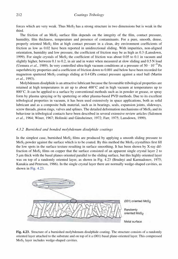
forces which are very weak. Thus MoS2 has a strong structure in two dimensions but is weak in thethird.
The friction of an MoS2 surface film depends on the integrity of the film, contact pressure,humidity, film thickness, temperature and presence of contaminants. For a pure, smooth, dense,properly oriented MoS2 film at high contact pressure in a clean, dry environment coefficients offriction as low as 0.02 have been reported in unidirectional sliding. With impurities, non-alignedorientation, humidity and low pressure, the coefficient of friction may be as high as 0.3 (Lansdown,1999). For single crystals of MoS2 the coefficient of friction was about 0.05 to 0.1 in vacuum andslightly higher, between 0.1 to 0.2, in air and in water when measured at slow sliding and 0.5 N load(Uemura et al., 1989). In very controlled ultra-high vacuum conditions at a pressure of 50 $ 10�9 Pasuperlubricity properties and a coefficient of friction down to 0.001 and below have been recorded formagnetron sputtered MoS2 coatings sliding at 0.4 GPa contact pressure against a steel ball (Martinet al., 1993).
Molybdenum disulphide is an attractive lubricant because the favourable tribological properties areretained at high temperatures in air up to about 400�C and in high vacuum at temperatures up to800�C. It can be applied to a surface by conventional methods such as in powder or grease, or sprayform by plasma spraying or by sputtering or other plasma-based PVD methods. Due to its excellenttribological properties in vacuum, it has been used extensively in space applications, both as solidlubricant and as a composite bulk material, such as in bearings, seals, expansion joints, slideways,screw threads, piston rings, valves and splines. The detailed deformation mechanisms of MoS2 and itsbehaviour in tribological contacts have been described in several extensive review articles (Salomonet al., 1964; Winer, 1967; Holinski and Gansheimer, 1972; Farr, 1975; Lansdown, 1999).
4.3.2 Burnished and bonded molybdenum disulphide coatings
In the simplest case, burnished MoS2 films are produced by applying a smooth sliding pressure toMoS2 powder against the surface which is to be coated. By this method the MoS2 crystallites first fillthe low spots in the surface texture resulting in surface smoothing. It has been shown by X-ray dif-fraction of MoS2 films on copper that the surface consisted of an apparent single crystal layer 2 to5 mm thick with the basal planes oriented parallel to the sliding surface, but this highly oriented layerwas on top of a randomly oriented layer, as shown in Fig. 4.23 (Brudnyi and Karmadonov, 1975;Kanakia and Peterson, 1986). In the single crystal layer there are normally wedge-shaped cavities, asshown in Fig. 4.23.
Fig. 4.23. Structure of a burnished molybdenum disulphide coating. The structure consists of a randomlyoriented layer attached to the substrate and on top of it a (001) basal plane-oriented layer. This compressedMoS2 layer includes wedge-shaped cavities.
212 Coatings Tribology

The burnished film is attached to the substrate mainly by three mechanisms: (1) infilling of lowspots on the surface, (2) embedment of crystallites in the surface and (3) chemical bonding betweenMoS2 and the surface material. By experience there seems to be little or no advantage in producingburnished films thicker than 20 mm. Other methods used to apply the film to the surface are by flo-tation, by dipping in dispersion or spraying, or the use of bonding agents (Lansdown, 1999).
The tribological behaviour of pre-rubbed MoS2 films sliding against a 4.76 mm radius steel rider inpin-on-disc experiments with a velocity of 2.6 m/s and a load of 10 N has been studied by Fusaro(1978). MoS2 powder with an average particle size of 10 mm was mechanically rubbed over a steeldisc surface producing a coating of 1 to 2 mm in thickness. The coefficient of friction was very low,only 0.01 to 0.02, in dry air and dry argon environments and showed good wear resistance with anendurance life up to about 100 kilocycles in dry air and 2000 kilocycles in dry argon.
In a moist air environment, the coefficient of friction increased to 0.08 and the endurance life wasonly about 10 kilocycles. The results indicate that water and oxygen are detrimental to MoS2
lubrication. A thin MoS2 layer was transferred to the steel rider surface but the amount of transferredmaterial did not affect the coefficient of friction. In moist air and dry air, the MoS2 film on the slidingsurfaces was transformed from a bright, metallic-coloured, coalesced film to a dark, black, lesscontinuous film. The rate of transformation depended on sliding time and whether or not the air at-mosphere contained water. As the rate of transformation increased the wear life decreased and therider wear rate increased. Little or no transformation of MoS2 was observed in dry argon. Thissupports the conclusion that the predominant chemical reaction taking place is oxidation of MoS2.
The lifecycle of a sliding MoS2 film may be divided into the following three periods: running-in,steady state and failure (Bartz and Xu, 1986; Gardos, 1988) as illustrated in Fig. 4.24.
1. In the running-in period under normal load and tangential shear, the film rapidly becomescompacted to a fraction of its original thickness and a transfer film is formed on the counterface.The basal planes of the exposed, hexagonal MoS2 crystallites become increasingly oriented on thecompacted surface of the film, parallel with the direction of sliding. A process of high-temperatureoxidation of the MoS2 film begins.
2. After a few hundred to a few thousand cycles, the reduction in film thickness essentially stops. Thisis the beginning of the steady-state period which represents the useful lifetime of the film. Duringthis long steady-state running period the coefficient of friction attains its lowest steady-state valueand the wear rate is low. The absolute level of friction depends on several factors such as load,velocity and humidity.
3. The failure period starts with the appearance of surface blisters or microfracture of the coating. Asthe blisters or wear fragments are repeatedly pressed down by the passing load they becomeprogressively more brittle, eventually breaking into fine, powdery debris. Blister formation anddelamination is accompanied by a gradual increase in friction. Soon major descaling leads togalling and catastrophic seizure. According to Gardos (1988) the oxidation of the MoS2 film withinthe layer and the consequent reduction in molar volume by etch-pitting, combined with gaseousoxidation products being trapped and frictionally heated within the coalesced free-volume regions,is the primary reason for blister formation. Large-scale delamination of blisters is the cause of thecharacteristic catastrophic failure of MoS2 films.
The influence of humidity on the frictional behaviour of burnished MoS2 films has been found to bereversible. Experimental data in the speed range of 0.0005 to 0.03 m/s, load range of 0.5 to 8 N andrange of relative humidity from 20 to 90% indicate that absorbed moisture causes the MoS2 film tomechanically soften and that the film is partly pushed ahead on the sides of moving contact spots (Gaoet al., 1993). As a result the film thickness between the contact spots decreases with humidity butincreases slightly with sliding speed and contact spot size – that is with load. Accordingly, theshearing part of the frictional resistance is little affected but the frictional contribution due to filmploughing rises with increasing humidity.
213Tribological Properties of Coatings
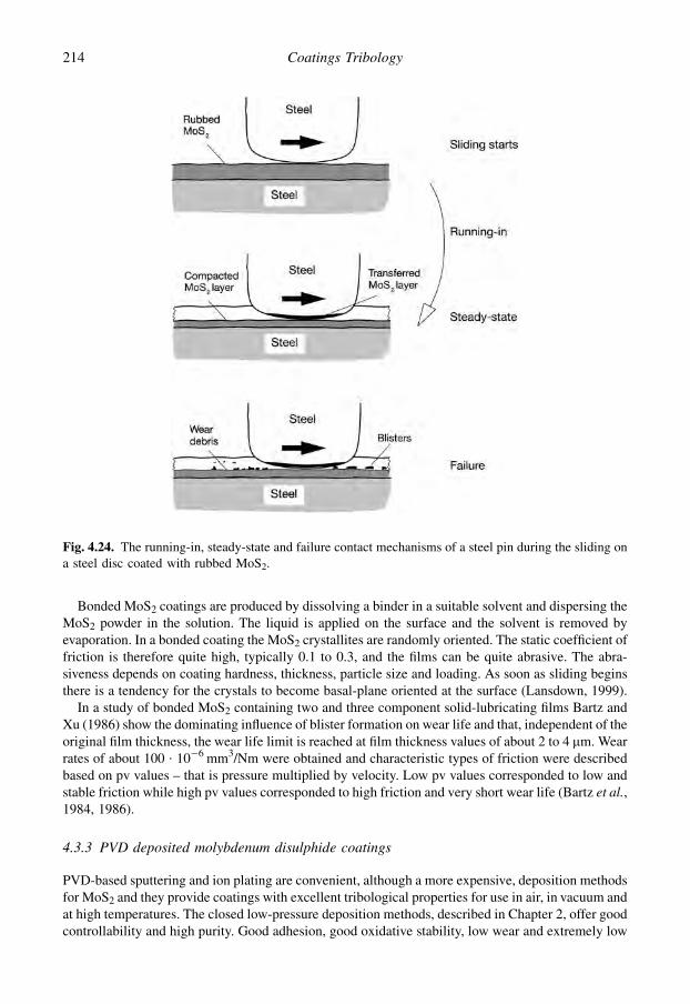
Bonded MoS2 coatings are produced by dissolving a binder in a suitable solvent and dispersing theMoS2 powder in the solution. The liquid is applied on the surface and the solvent is removed byevaporation. In a bonded coating the MoS2 crystallites are randomly oriented. The static coefficient offriction is therefore quite high, typically 0.1 to 0.3, and the films can be quite abrasive. The abra-siveness depends on coating hardness, thickness, particle size and loading. As soon as sliding beginsthere is a tendency for the crystals to become basal-plane oriented at the surface (Lansdown, 1999).
In a study of bonded MoS2 containing two and three component solid-lubricating films Bartz andXu (1986) show the dominating influence of blister formation on wear life and that, independent of theoriginal film thickness, the wear life limit is reached at film thickness values of about 2 to 4 mm. Wearrates of about 100 $ 10�6 mm3/Nm were obtained and characteristic types of friction were describedbased on pv values – that is pressure multiplied by velocity. Low pv values corresponded to low andstable friction while high pv values corresponded to high friction and very short wear life (Bartz et al.,1984, 1986).
4.3.3 PVD deposited molybdenum disulphide coatings
PVD-based sputtering and ion plating are convenient, although a more expensive, deposition methodsfor MoS2 and they provide coatings with excellent tribological properties for use in air, in vacuum andat high temperatures. The closed low-pressure deposition methods, described in Chapter 2, offer goodcontrollability and high purity. Good adhesion, good oxidative stability, low wear and extremely low
Fig. 4.24. The running-in, steady-state and failure contact mechanisms of a steel pin during the sliding ona steel disc coated with rubbed MoS2.
214 Coatings Tribology
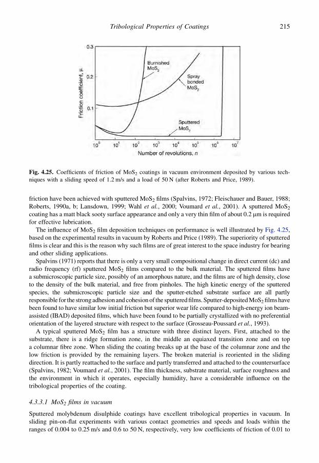
friction have been achieved with sputtered MoS2 films (Spalvins, 1972; Fleischauer and Bauer, 1988;Roberts, 1990a, b; Lansdown, 1999; Wahl et al., 2000; Voumard et al., 2001). A sputtered MoS2
coating has a matt black sooty surface appearance and only a very thin film of about 0.2 mm is requiredfor effective lubrication.
The influence of MoS2 film deposition techniques on performance is well illustrated by Fig. 4.25,based on the experimental results in vacuum by Roberts and Price (1989). The superiority of sputteredfilms is clear and this is the reason why such films are of great interest to the space industry for bearingand other sliding applications.
Spalvins (1971) reports that there is only a very small compositional change in direct current (dc) andradio frequency (rf) sputtered MoS2 films compared to the bulk material. The sputtered films havea submicroscopic particle size, possibly of an amorphous nature, and the films are of high density, closeto the density of the bulk material, and free from pinholes. The high kinetic energy of the sputteredspecies, the submicroscopic particle size and the sputter-etched substrate surface are all partlyresponsible for the strong adhesion and cohesion of the sputtered films. Sputter-deposited MoS2 films havebeen found to have similar low initial friction but superior wear life compared to high-energy ion beam-assisted (IBAD) deposited films, which have been found to be partially crystallized with no preferentialorientation of the layered structure with respect to the surface (Grosseau-Poussard et al., 1993).
A typical sputtered MoS2 film has a structure with three distinct layers. First, attached to thesubstrate, there is a ridge formation zone, in the middle an equiaxed transition zone and on topa columnar fibre zone. When sliding the coating breaks up at the base of the columnar zone and thelow friction is provided by the remaining layers. The broken material is reoriented in the slidingdirection. It is partly reattached to the surface and partly transferred and attached to the countersurface(Spalvins, 1982; Voumard et al., 2001). The film thickness, substrate material, surface roughness andthe environment in which it operates, especially humidity, have a considerable influence on thetribological properties of the coating.
4.3.3.1 MoS2 films in vacuum
Sputtered molybdenum disulphide coatings have excellent tribological properties in vacuum. Insliding pin-on-flat experiments with various contact geometries and speeds and loads within theranges of 0.004 to 0.25 m/s and 0.6 to 50 N, respectively, very low coefficients of friction of 0.01 to
Fig. 4.25. Coefficients of friction of MoS2 coatings in vacuum environment deposited by various tech-niques with a sliding speed of 1.2 m/s and a load of 50 N (after Roberts and Price, 1989).
215Tribological Properties of Coatings

0.04, wear rates of only 0.001 $ 10�6 mm3/Nm and excellent film endurances have been measured bySpalvins (1972), Dimigen et al. (1985), Roberts (1989), Didziulis et al. (1990) and Miyoshi et al.(1993). Even lower friction, coefficients of friction down to 0.001 and below, was measured by Martinet al. (1993) in very controlled ultra-high vacuum conditions. This is remarkable since this value is thelowest ever measured between two solids in dry sliding. This condition is called superlubricity and isdiscussed in more detail later in this chapter.
In early experiments Spalvins (1972) observed that for a higher load of 10 N, the film endurance lifewas short (38,000 revolutions) and the coefficient of friction was as low as 0.02, while at a lower loadof 2.5 N the endurance was almost one order of magnitude higher (250,000 revolutions) but thecoefficient of friction at the same time was 0.04. A decreasing coefficient of friction with increasingload has also been reported by Roberts. At very low speeds, less than 0.001 m/s, the coefficient offriction decreases with increasing sliding speed (Roberts, 1990b) while it is unaffected at higherspeeds (Spalvins, 1972).
The influence of surface roughness has been studied by Roberts and Price (1989) and Roberts et al.(1992) and they observed that with a higher roughness of Ra¼ 0.12 mm the coefficient of frictiondecreased from 0.02 to 0.01 and the film endurance was very good (250,000 revolutions). Fora smoother coated surface of Ra¼ 0.04 mm the coefficient of friction was considerably higher, in therange 0.02 to 0.04 and the film endurance only 20,000 revolutions, as shown in Fig. 4.26. This issupported by the observations of Spalvins (1972) that the surfaces he used always had to be roughenedto obtain a longer wear life. The wear life is believed to be extended due to an increased surfaceconcentration of the lubricating surface film with the increased volume of surface depressions tocontain MoS2 as long as metal to metal contacts of asperities are still avoided. Roberts (1990b)suggests that for a 1 mm thick film there exists an optimum level of substrate surface roughness atwhich friction is minimized and film endurance maximized.
4.3.3.2 Superlubricity
It is remarkable that in ultra-high vacuum conditions with a minimum pressure of 10 to 50 $ 10�9 Paextremely low friction, named superlubricity, with coefficients of friction down to 0.001 and belowhas been measured by Martin and his colleagues (Martin et al., 1993, 1994; Donnet et al., 1993; LeMogne et al., 1994; Erdemir and Martin, 2007; Martin, 2007). Since this is the lowest frictionmeasured between two sliding surfaces in dry contact it is of course of interest to study this
Fig. 4.26. Effect of surface roughness on the coefficient of friction and lifetime of sputtered MoS2
coatings with a sliding speed of 1.2 m/s and a load of 50 N (data from Roberts and Price, 1989).
216 Coatings Tribology

mechanism in more detail. The experimental conditions used were a pin-on-flat test rig with a 4 mmradius hemispherical steel pin sliding at a normal load of 1.2 N, corresponding to 0.4 GPa contactpressure, at a very slow sliding speed of 0.5 mm/s. The coated surface was a 0.12 mm thick rf mag-netron sputtered pure MoS2 film on cleaned bearing steel. The crystal structure was hexagonal and theS/Mo ratio was 2.04, thus corresponding to a nearly stochiometric structure, with most of the crys-tallites having their basal planes oriented perpendicular to the surface before sliding.
A relatively high and constant hardness value of 7.8 GPa and high reduced elastic modulus of 165to 170 GPa was measured for the superlubricious MoS2 films. Thus the film is very dense and compactwith hardness and elastic modulus at least two times higher than the normal coatings containing someporosity. Auger electron spectroscopy analysis did not show any trace of contamination elements suchas carbon or oxygen. Very low shear strength values down to 1 MPa were measured for these films(Martin et al., 1994). Initially, the coefficient of friction was 0.01 but drastically decreased to about0.001 after a few cycles as shown in Fig. 4.27.
The explanation for the extremely low friction seems to be the following:
1. The surfaces were extremely smooth to avoid friction due to asperity deformation.2. The coating was very hard and dense to avoid ploughing friction.3. The shear probably almost completely took place in planes of extremely weak bonding by van der
Waals intermolecular forces between the MoS2 planes.4. The surfaces were atomically clean to avoid structural disturbances in the shear planes.5. The sliding plane structure was incommensurate atomic lattices. This means that the friction is
minimized when a misfit angle shifts in two superimposed sliding crystal planes with respect toeach other as visualized in Fig. 4.28.
4.3.3.3 Transfer layers and interfacial shear in MoS2 films
Surface reaction, wear products and interfacial films play an important role in the wear and friction ofMoS2 coated sliding surfaces. The contact mechanisms in the running-in and steady-state period of
Fig. 4.27. Coefficient of friction versus the number of reciprocating sliding cycles of pure and contam-inated MoS2 coatings. The coefficient of friction for pure MoS2 coatings is 0.001 and even below (afterDonnet, 1998a).
217Tribological Properties of Coatings

the lifecycle of the film have a similarity with those for rubbed MoS2 films shown in Fig. 4.24. In theearly stage of an MoS2 coated surface sliding against a countersurface a thin transferred layer is builtup on the counterface. Singer et al. (2003) have shown with in situ observations how MoS2 coatingmaterial is transferred to and from third body reservoirs on the surface to protect wear spots in thesliding contact. In some cases it has been observed that the wear particles are ejected beyond the weartrack instead of remaining inside the contact zone. Why some coatings form reservoirs and give longlife, while others eject the wear debris and fail early, is not understood.
The sliding process induces a preferred orientation in the contacting layers, so that basally orientedMoS2 transfer layers and basally oriented MoS2 wear tracks are generated during the steady-statesliding (Fayeulle et al., 1990). These orientations are conducive to low shear strength and hence lowfriction. In favourable contact conditions the wear of the MoS2 coating may take place even as a layer-by-layer process at the atomic level (Wahl et al., 1999).
The generation of wear products, the formation of transfer films, their development to formmaterial reservoirs and the kinematics of the material transfer process during sliding have beendemonstrated by Singer et al. (2003) in pin-on-disc measurements with a glass 6.35 mm radiushemisphere sliding against a 0.3 mm thick Pb–Mo–S coating on a steel substrate with 1 mm/s slidingspeed and 24 N load. They first observed how patchy transfer films attached to the contact area of theglass hemisphere and later thicker compact pads of debris were formed at the leading and trailingedges. The observation confirmed that the relative motion between the transfer film on the hemisphereand the wear track on the coating took place by interfacial sliding. Analysis showed that the top layerson both surfaces, that is the plane where the shear took place, were layers of MoS2.
4.3.3.4 MoS2 films in dry and humid air
It is well known that humidity has an adverse effect on the tribological properties of MoS2. It has beenrecommended that the humidity level should be below 5%, or failing this below 20%, to achievea good tribological performance with traditional MoS2 coatings in an air environment (Roberts, 1986,1987). For sputtered MoS2 films Nabot et al. (1990) measured an increase in the coefficient of frictionfrom 0.05 to 0.27 when the relative humidity (RH) was increased from 5 to 60%, as shown in
Fig. 4.28. Visualization of two superimposed hexagonal lattices, representing adjacent sulphur planes inMoS2, with a misfit angle of q. The frictional force is known to be minimum at q¼ 30� (after Donnet,1998a).
218 Coatings Tribology

Fig. 4.29. A significant increase in wear was observed at the same time. This is in good agreementwith the remarkable reduction in MoS2 film lifetime from 100,000 to 300,000 revolutions in a dry airenvironment to 700 to 900 revolutions in humid air of RH¼ 52% at a speed of 0.01 m/s and a load of5 N, reported by Niederhauser et al. (1983). However, Niederhauser also showed that the negativeeffect of humidity can be overcome by using a suitable interlayer such as rhodium.
The humidity effect has further been confirmed in the sliding conditions referred to above by Singeret al. (2003). In dry air (RH< 1%) the coefficient of friction was about 0.05 but it increased quickly to0.17 as humid air (RH¼ 50%) was introduced. The coefficient of friction soon returned to its originallevel when changing back to dry air. A similar behaviour has been recorded in fretting tests by Zhanget al. (2003a). They measured a coefficient of friction increasing from 0.06 to 0.14 as relative hu-midity increased from 10 to 90% for MoS2 coatings with basal orientation and an increase from 0.25to 0.42 for coatings with random orientation at a normal load of 1 N, oscillation of 10 Hz and with5 mm radius corundum balls as the counterface. The wear rates were in the range of 5 to20 $ 10�6 mm3/Nm for basal oriented and 10 to 80 $ 10�6 mm3/Nm for randomly oriented coatings.
The effect of humidity on the friction and wear of sputtered MoS2 coatings has been explained asbeing due to the formation of oxides in the contact interlayers, as earlier described for bonded MoS2
films. Fayeulle et al. (1990) have discussed in detail the formation process of different Mo and Feoxides that can be assumed to occur in these kinds of contacts. Experimentally, they observed that thewear rate of MoS2 films is considerably lower in argon than in air, which can be explained by the factthat molybdenum oxides are formed more slowly in argon. The interfacial films formed in air weremuch thicker and usually contained more oxygen than sulphur. The mechanism for the change infriction has been suggested to be the effect of the transfer film on the real area of contact (Wheeler,1993). Thick, smooth films produce large areas of contact having higher friction coefficients than thesmaller contact areas produced by thin films. On the other hand, Singer et al. (2003) have suggestedthat the increase of friction in humid air is more likely to be due to an increase in the interfacial shearstrength.
Sputtered MoS2 coatings generally contain oxygen as a surface species and as a bulk contaminant,up to 20 at.%. Surface analytical studies and friction and wear tests with MoS2 coated steels haveshown that surface oxygen participates in both the adhesion and wear of transfer layers. In addition to
Fig. 4.29. The influence of relative humidity (RH) on the coefficient of friction for a sputtered MoS2
coated surface sliding against a steel ball with a speed of 0.01 m/s and a load of 5 N (data from Nabotet al., 1990).
219Tribological Properties of Coatings

MoS2, MoO3 and several ternary oxides of the counterface material, such as iron from steel and cobaltfrom WC:Co, have been found and described by Singer (1991). He also showed that the quaternaryphase diagram for an Mo�S–Fe–O system gives a good indication of the phases detected.
When an MoS2 layer is not subjected to sliding for a certain period the coefficient of friction may beup to four times higher when restarting sliding (Roberts, 1990b). This is thought to result from theadsorption of water molecules within the MoS2 monolayer. With continued sliding these are removed,probably by desorption induced by frictional heating, and the coefficient of friction decreases.
In dry air ball-on-plate experiments at a speed of 0.02 m/s, in a load range of 1 to 30 N and at roomtemperature, Singer et al. (1990) observed that the coefficient of friction decreased with increasingload and was proportional to (load)n with the exponent n¼�0.32.
4.3.3.5 Thickness of MoS2 coatings
The reported MoS2 sputtered coatings with favourable tribological properties have, in general, beenvery thin, with coating thicknesses within the range of 0.1 to 2 mm. Some decrease in the thickness ofthe film can be assumed to take place during the process of sliding. Spalvins (1982) found that theoptimal lubricating film is usually about 0.2 mm thick.
Muller et al. (1988) studied thick, compact MoS2 coatings produced by dc as well as rf magnetronsputtering. Coatings with a thickness up to 30 mm were obtained without a change in morphology. Theadhesion was good for coatings on steel, silicon and glass substrates. An improved lifetime for thecoating was measured for increasing coating thicknesses up to 3 mm as shown in Fig. 4.30. The testswere accelerated by using a humid environment with RH¼ 98%. For sputtered MoS2 films withthicknesses ranging from 0.7 to 28 mm, Aubert et al. (1990) measured minimum values for thecoefficient of friction at film thicknesses of about 3 mm for smooth surfaces and 1 mm for roughsurfaces in pin-on-disc experiments in air at a sliding velocity of 0.01 m/s and a load of 5 N.
Thicker coatings provide an interesting possibility for use on rougher surfaces. The investigation byMuller et al. (1988) gives clear evidence that thick MoSx coatings adhere well in pin-on-disc tests onturned surfaces.
4.3.3.6 Counterface, substrate materials and interlayers
The prevailing environment must be considered in association with the influence of counterface,substrate materials and interlayers on the tribological properties of MoS2. In humid air the process of
Fig. 4.30. Lifetime in number of revolutions until the friction coefficient exceeds 0.3 for sputteredcompact MoSx coatings of different thicknesses on polished steel plates sliding against a steel pin in pin-on-disc tests with a velocity of 0.1 m/s and a load of 5 N (data from Muller et al., 1988).
220 Coatings Tribology
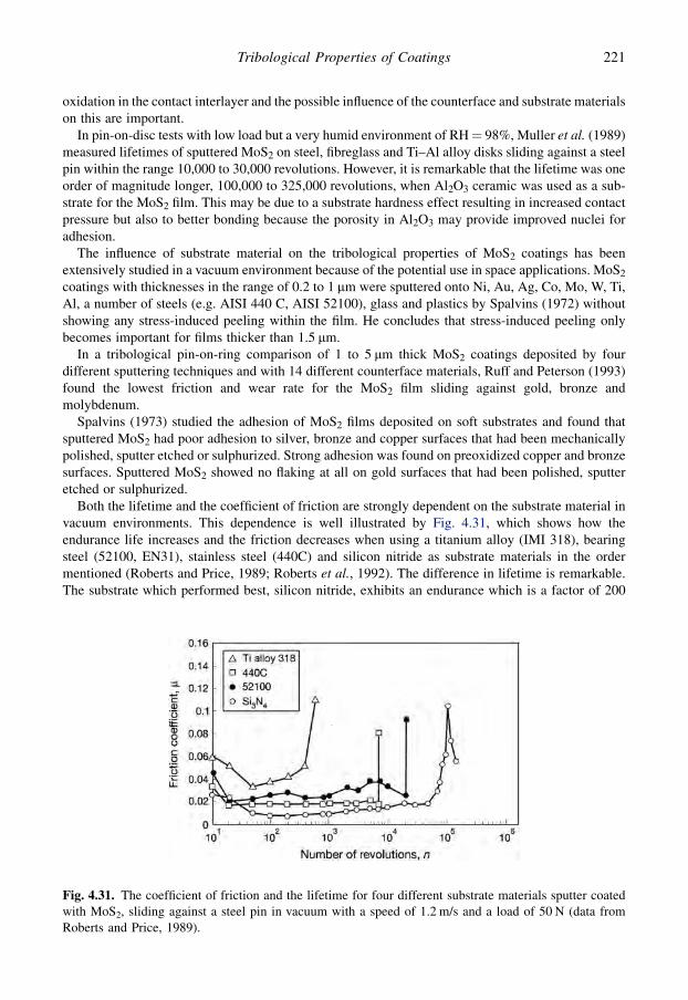
oxidation in the contact interlayer and the possible influence of the counterface and substrate materialson this are important.
In pin-on-disc tests with low load but a very humid environment of RH¼ 98%, Muller et al. (1989)measured lifetimes of sputtered MoS2 on steel, fibreglass and Ti–Al alloy disks sliding against a steelpin within the range 10,000 to 30,000 revolutions. However, it is remarkable that the lifetime was oneorder of magnitude longer, 100,000 to 325,000 revolutions, when Al2O3 ceramic was used as a sub-strate for the MoS2 film. This may be due to a substrate hardness effect resulting in increased contactpressure but also to better bonding because the porosity in Al2O3 may provide improved nuclei foradhesion.
The influence of substrate material on the tribological properties of MoS2 coatings has beenextensively studied in a vacuum environment because of the potential use in space applications. MoS2
coatings with thicknesses in the range of 0.2 to 1 mm were sputtered onto Ni, Au, Ag, Co, Mo, W, Ti,Al, a number of steels (e.g. AISI 440 C, AISI 52100), glass and plastics by Spalvins (1972) withoutshowing any stress-induced peeling within the film. He concludes that stress-induced peeling onlybecomes important for films thicker than 1.5 mm.
In a tribological pin-on-ring comparison of 1 to 5 mm thick MoS2 coatings deposited by fourdifferent sputtering techniques and with 14 different counterface materials, Ruff and Peterson (1993)found the lowest friction and wear rate for the MoS2 film sliding against gold, bronze andmolybdenum.
Spalvins (1973) studied the adhesion of MoS2 films deposited on soft substrates and found thatsputtered MoS2 had poor adhesion to silver, bronze and copper surfaces that had been mechanicallypolished, sputter etched or sulphurized. Strong adhesion was found on preoxidized copper and bronzesurfaces. Sputtered MoS2 showed no flaking at all on gold surfaces that had been polished, sputteretched or sulphurized.
Both the lifetime and the coefficient of friction are strongly dependent on the substrate material invacuum environments. This dependence is well illustrated by Fig. 4.31, which shows how theendurance life increases and the friction decreases when using a titanium alloy (IMI 318), bearingsteel (52100, EN31), stainless steel (440C) and silicon nitride as substrate materials in the ordermentioned (Roberts and Price, 1989; Roberts et al., 1992). The difference in lifetime is remarkable.The substrate which performed best, silicon nitride, exhibits an endurance which is a factor of 200
Fig. 4.31. The coefficient of friction and the lifetime for four different substrate materials sputter coatedwith MoS2, sliding against a steel pin in vacuum with a speed of 1.2 m/s and a load of 50 N (data fromRoberts and Price, 1989).
221Tribological Properties of Coatings

higher than the poorest substrate, the titanium alloy. Roberts and Price conclude that the endurance ofthe films is strongly related to adhesion and they find evidence for this by the presence of interfacialchemical bonds on the steel and ceramic substrates and their absence on titanium alloy. However, thisdoes not explain the large difference between the film endurances observed between the ceramic andthe steel substrates. On the other hand, it is interesting to note that the film endurance is almost di-rectly related to the hardness of the materials. It seems probable that the substrate hardness might bepart of the explanation. In contradiction to this are the vacuum pin-on-disc results by Didziulis et al.(1990), showing that sputtered MoS2 films deposited on silicon carbide have significantly shorter wearlives than films deposited on steel.
Roberts and Price (1989) have observed that for metallic substrate materials, film failure wassignalled by an abrupt increase in the coefficient of friction, but for the ceramic substrate, film failureoccurred gradually, as evidenced by a slower increase in friction lasting some 50,000 revolutions. Thecoefficient of friction decreases with increasing elastic modulus of the substrate materials and thisbehaviour is ascribed to changes in the true contact area.
The tribological properties of sputtered MoS2 coatings can be improved by the use of thin, hardinterlayers that improve the adhesion between the MoS2 coating and the substrate and increase theload-carrying capacity and thus decrease the contact area. Good results have been achieved withinterlayers of Ti, TiB2, BN and even with rhodium and ruthenium (Niederhauser et al., 1983; Roberts,1990b; Teer, 2001; Steinmann et al., 2004). In a comparison of the tribological performance of MoS2
films deposited by fast atom beam sputtering on a steel SUS 440 C plate with and without a hard B orBN interlayer, Kuwano (1990) observed that the coefficient of friction decreased by a factor of five toa value as low as 0.005 and the endurance lifetime was prolonged by a factor of ten, up to 10,000 to20,000 sliding cycles, when the hard interlayers were used.
4.3.3.7 Coating composition
The PVD technique offers a possibility to deposit coatings with a large variety of different compo-sitions and structures. For MoS2 coatings the tribological performance will depend considerably onthe sulphur/molybdenum composition in the coating and the use of compound materials in thecoating.
The influence of the sulphur/molybdenum ratio in sputtered MoSx films on their tribologicalproperties when sliding against steel has been studied by Aubert et al. (1990) and Nabot et al. (1990).A minimum value, 0.025, for the coefficient of friction was found at S/Mo ratios of approximately 1.5for crystallized (001)-oriented films with a hardness (10 g load) of 5000 MPa assessed via a Knoopdevice, as shown in Fig. 4.32. These properties correspond to the lowest shear stress. For both higherand lower S/Mo ratios the coefficient of friction rapidly rises to a value of about 0.06. The best wearresistance in collar-shaft experiments was observed for films with an S/Mo ratio of 1.8 exhibitinga hardness of 2000 MPa.
Adding small amounts of some doping material, mainly metals, to the MoS2 coating can havea considerable positive effect on the friction and wear properties of the coated surface. The effect iscomplex and not well understood, but it seems to be related to improvement of the hardness andstrengthening of the coating structure. The most successful dopants used to build up a compoundMoS2 coating structure are Ti and Pb. In addition other compound materials such as MoS2 with Ni, Cr,Au, C, TiB2 and WSe2 have been applied (Stupp, 1981; Simmonds et al., 1998, 2000; Wahl et al.,1999; Savan et al., 2000; Teer, 2001; Voumard et al., 2001; Singer et al., 2003; Lince, 2005;Steinmann et al., 2004; Kao, 2005; Amaro et al., 2005).
Improved lifetime and a much more uniform sliding friction in tests in air were measured by Stupp(1981) when adding 5 to 7% (assumed vol.%) of Ni or Ti to the MoS2 coating. Optimal tribologicalperformance both in sliding and drilling tests was observed by Kao (2005) with the addition of 5 to 8at.% Cr to the MoS2 coating. The measured average coefficient of friction was between 0.04 and 0.06.
222 Coatings Tribology
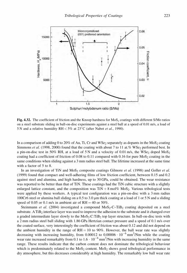
In a comparison of adding 0 to 20% of Au, Ti, Cr and WSe2 separately as dopants in the MoS2 coatingSimmons et al. (1998, 2000) found that the coating with about 7 to 11 at.% WSe2 performed best. Ina pin-on-disc test in 50% RH, at a load of 5 N and a velocity of 0.01 m/s, the WSe2 doped MoS2
coating had a coefficient of friction of 0.08 to 0.11 compared with 0.16 for pure MoS2 coating in thesame conditions when sliding against a 3 mm radius steel ball. The lifetime increased at the same timewith a factor of 5 to 8.
In an investigation of TiN and MoS2 composite coatings Gilmore et al. (1998) and Goller et al.(1999) found that compact and well-adhering films of low friction coefficient, between 0.15 and 0.2against steel and alumina, and high hardness, up to 30 GPa, could be obtained. The wear resistancewas reported to be better than that of TiN. These coatings had the TiN cubic structure with a slightlyenlarged lattice constant, and the composition was TiNþ 8 mol% MoS2. Various tribological testswere applied by these workers. A typical test configuration was a pin-on-disc with a 3 mm radius100Cr6 steel or alumina ball sliding on a 0.5 to 3.0 mm thick coating at a load of 1 or 5 N and a slidingspeed of 0.05 or 0.1 m/s in ambient air of RH¼ 40 or 50%.
Steinmann et al. (2004) investigated a compound MoS2-C–TiB2 coating deposited on a steelsubstrate. ATiB2 interface layer was used to improve the adhesion to the substrate and it changed overa graded intermediate layer slowly to the MoS2:C:TiB2 top layer structure. In ball-on-disc tests witha 2 mm radius steel ball sliding with 1.86 GPa Hertzian contact pressure and a speed of 0.1 m/s overthe coated surface, very interestingly the coefficient of friction was about 0.12 and did not depend onthe ambient humidity in the range of RH¼ 10 to 90%. However, the ball wear rate was slightlydecreasing with increasing humidity, from 0.00012 to 0.00006 $ 10�6 mm3/Nm while the coatingwear rate increased remarkably from 0.1 to 1.6 $ 10�6 mm3/Nm with increasing humidity in the samerange. These results indicate that the carbon content does not dominate the tribological behaviourwhich is predominately related to the MoS2 content. MoS2 shows good tribological performance indry atmosphere, but this decreases considerably at high humidity. The remarkably low ball wear rate
Fig. 4.32. The coefficient of friction and the Knoop hardness for MoSx coatings with different S/Mo ratioson a steel substrate sliding in ball-on-disc experiments against a steel ball at a speed of 0.01 m/s, a load of5 N and a relative humidity RH< 5% at 23�C (after Nabot et al., 1990).
223Tribological Properties of Coatings

indicates that there was a strong and continuous transfer layer built up on the steel surface protecting itfrom wear.
The addition of lead to an MoS2 coating has been shown to give very good tribological properties.Singer et al. coated both steel and Si substrates with amorphous Pb–Mo–S coatings containing 4 to 26at.% Pb in the thickness range of 0.2 to 0.5 mm (Wahl et al., 1999; Singer et al., 2003). Excellent wearresistance and very low friction with a coefficient of friction down to 0.05 in dry air at RH< 1% and 0.17at RH¼ 50% was measured when sliding against a 6.3 mm radius glass ball at a load of 24 N and a speedof 1 mm/s in dry air. Surface analysis gave direct evidence that in these low-speed, high-stress slidingconditions a tribochemical process can convert the amorphous Pb–Mo–S coating material into crystallineMoS2 which will form the active shear layer. The transformation occurs by creating basal-oriented layersat the outermost layers of the track and shows that wear takes place layer by layer at the atomic level.However, it is not clear why the Pb–Mo–S coating has a better resistance to wear than MoS2 coatings.A microstructure without MoS2 planes in the bulk might be one explanation, especially if this micro-structure inhibits fracture within the coating. However, Wahl et al. consider that the high endurance of thePb–Mo–S coating is mainly due to the slow wear process with MoS2 layers easily shearing and trans-ferring from and to the ball surface. The role of the Pb in the coating is still not understood.
The addition of Ti both as an interface layer and as a dopant to MoS2 coatings has given excellenttribological behaviour. Atmospheric testing of 1 mm thick MoS2–Ti coatings with 15% Ti has shownthat the friction is load dependent but is typically 0.02 at high contact pressure of 3.5 GPa while themaximum value was 0.08 and the wear rate was only 0.01 $ 10�6 mm3/Nm (Teer, 2001; Amaro et al.,2005; Michalczewski et al., 2007; Wang et al., 2007). Teer et al. explain the excellent adhesion, wearand friction properties by pointing out that previous deposition methods have resulted in structuresconsisting of a MoS2 matrix with small islands of metallic inclusions or multilayers, as this newMoS2–Ti structure contains no metallic inclusions and the titanium is thought to be in solid solutionwithin the MoS2. Evidence indicates that the Ti atoms are situated between the neighbouring S planesas presented in Fig. 4.33. It is probable that the distortion caused by the Ti atoms is responsible for the
Fig. 4.33. The structure of the MoS2–Ti coating showing the probable positioning of the titanium atoms inthe MoS2 structure (after Teer, 2001).
224 Coatings Tribology
increase in hardness. Also the presence of the Ti atoms within the MoS2 structure may be responsiblefor reducing the sensitivity of the coating to the water vapour. Still the low friction values indicate thatpure MoS2 crystallites are active at the top surface where shear takes place. When the amount of Ti inthe film is increased the hardness also increases to a maximum of about 2000 Hv at around 18% Ticontent. Above this level, the solubility level of the Ti is exceeded and multilayers are formedresulting in a decrease in the tribological performance.
The tribological properties in moist air have been improved by co-deposition of PTFE and MoS2.Niederhauser et al. (1983) have measured in pin-on-disc tests a reduction of the coefficient of frictionfrom about 0.25 to around 0.1 by the addition of PTFE to MoS2. The lifetime of the film was at thesame time prolonged by an order of magnitude. Further improvements in film endurance wereachieved by using chemically activated interlayers of rhodium or ruthenium in combination with theMoS2–PTFE coating.
4.3.3.8 Selection of MoS2 films
A systematic approach to the design and selection of MoS2 coatings for different purposes wasdeveloped by Fleischauer et al. (1990) and is outlined below. Fleischauer and his co-workers considerthree primary material properties – composition or phase purity, adhesion and morphology andporosity – to be the primary drivers of the three most important performance parameters, friction,endurance and debris generation.
They claimed that the choice of the proper MoS2 film for a specific use depends on the contactgeometry, stress levels and a trade-off between operational life and environmental factors both instorage and in use. The ideal combination of good adhesion, chemical purity and dense small-grainsize in MoS2 films provides the best lubrication and endurance in most relatively high-contact stressconditions with moderate operating lifetimes (108 to 1010 revolutions) such as ball bearings. Thiscombination of optimal film properties can be obtained by high-rate, ambient temperature (less than70�C) sputtering. Optimal properties can also be obtained by post-deposition ion processing withhigh-energy ions or by low-energy ion processing during deposition.
Other applications such as telescopic joints, release mechanisms, actuators and solar array drivemechanisms may not require the optimal endurance but may need protection from environmental ef-fects. Ultra-low friction can be obtained with resistance toward oxidation, by using high-temperaturegrowth conditions that induce larger crystallite and grain formation. Such films generate relatively largewear particles during operation that can cause noise in torque sensitive applications and are thusrecommended only if torque stability is not critical.
4.4 Hard Coatings
A thin hard coating on a softer, tough, substrate has proved to be a tribologically very beneficialmaterial combination. Many new coatings have been investigated and developed since the 1970s andalso taken successfully into commercial use.
A hard layer on a softer substrate will give improved protection against scratching from a hardcounterface or debris. Hard coatings have thus been especially useful in applications involvingabrasive or erosive wear. An early successful application was ceramic coatings, especially aluminiumoxide, titanium nitride and titanium carbide, on cutting tools where they give good protection againsta combination of diffusion and abrasive wear at high temperatures. This has often resulted inextensions of tool lifetimes by ten times and more. However, these coatings normally exhibit highfriction and are not suitable for low-friction sliding applications.
The second successful new coating taken widely into commercial use were the hard carbon-basedones, especially the group of coatings named diamond-like carbon (DLC). These coatings form a hardfilm on the surface reducing scratching and offer a good load-carrying capacity, and in addition they
225Tribological Properties of Coatings
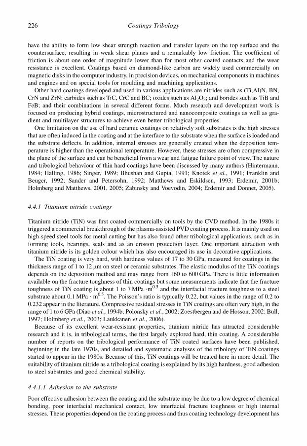
have the ability to form low shear strength reaction and transfer layers on the top surface and thecountersurface, resulting in weak shear planes and a remarkably low friction. The coefficient offriction is about one order of magnitude lower than for most other coated contacts and the wearresistance is excellent. Coatings based on diamond-like carbon are widely used commercially onmagnetic disks in the computer industry, in precision devices, on mechanical components in machinesand engines and on special tools for moulding and machining applications.
Other hard coatings developed and used in various applications are nitrides such as (Ti,Al)N, BN,CrN and ZrN; carbides such as TiC, CrC and BC; oxides such as Al2O3; and borides such as TiB andFeB; and their combinations in several different forms. Much research and development work isfocused on producing hybrid coatings, microstructured and nanocomposite coatings as well as gra-dient and multilayer structures to achieve even better tribological properties.
One limitation on the use of hard ceramic coatings on relatively soft substrates is the high stressesthat are often induced in the coating and at the interface to the substrate when the surface is loaded andthe substrate deflects. In addition, internal stresses are generally created when the deposition tem-perature is higher than the operational temperature. However, these stresses are often compressive inthe plane of the surface and can be beneficial from a wear and fatigue failure point of view. The natureand tribological behaviour of thin hard coatings have been discussed by many authors (Hintermann,1984; Halling, 1986; Singer, 1989; Bhushan and Gupta, 1991; Knotek et al., 1991; Franklin andBeuger, 1992; Sander and Petersohn, 1992; Matthews and Eskildsen, 1993; Erdemir, 2001b;Holmberg and Matthews, 2001, 2005; Zabinsky and Voevodin, 2004; Erdemir and Donnet, 2005).
4.4.1 Titanium nitride coatings
Titanium nitride (TiN) was first coated commercially on tools by the CVD method. In the 1980s ittriggered a commercial breakthrough of the plasma-assisted PVD coating process. It is mainly used onhigh-speed steel tools for metal cutting but has also found other tribological applications, such as informing tools, bearings, seals and as an erosion protection layer. One important attraction withtitanium nitride is its golden colour which has also encouraged its use in decorative applications.
The TiN coating is very hard, with hardness values of 17 to 30 GPa, measured for coatings in thethickness range of 1 to 12 mm on steel or ceramic substrates. The elastic modulus of the TiN coatingsdepends on the deposition method and may range from 160 to 600 GPa. There is little informationavailable on the fracture toughness of thin coatings but some measurements indicate that the fracturetoughness of TiN coating is about 1 to 7 MPa $m0.5 and the interfacial fracture toughness to a steelsubstrate about 0.1 MPa $ m0.5. The Poisson’s ratio is typically 0.22, but values in the range of 0.2 to0.232 appear in the literature. Compressive residual stresses in TiN coatings are often very high, in therange of 1 to 6 GPa (Diao et al., 1994b; Polonsky et al., 2002; Zoestbergen and de Hosson, 2002; Bull,1997; Holmberg et al., 2003; Laukkanen et al., 2006).
Because of its excellent wear-resistant properties, titanium nitride has attracted considerableresearch and it is, in tribological terms, the first largely explored hard, thin coating. A considerablenumber of reports on the tribological performance of TiN coated surfaces have been published,beginning in the late 1970s, and detailed and systematic analyses of the tribology of TiN coatingsstarted to appear in the 1980s. Because of this, TiN coatings will be treated here in more detail. Thesuitability of titanium nitride as a tribological coating is explained by its high hardness, good adhesionto steel substrates and good chemical stability.
4.4.1.1 Adhesion to the substrate
Poor effective adhesion between the coating and the substrate may be due to a low degree of chemicalbonding, poor interfacial mechanical contact, low interfacial fracture toughness or high internalstresses. These properties depend on the coating process and thus coating technology development has
226 Coatings Tribology

aimed at optimizing the deposition process to achieve the most favourable combination of the above-mentioned properties – resulting in highly effective adhesion. The mechanisms operating are notalways well understood, but the optimization has nevertheless been quite successful.
It has been shown that high levels of ionization efficiency during the plasma-assisted PVD processproduce films with improved structural, compositional and hardness properties (Matthews, 1980;Matthews and Sundquist, 1983; Matthews, 1985; Matthews et al., 1993). A titanium interlayer,normally with a thickness of about 100 nm, between the TiN coating and the steel substrate canimprove the adhesion and result in better tribological properties (Valli et al., 1985a; Cheng et al.,1989; Rickerby et al., 1990). The scratch test method has been widely used to evaluate the adhesionbetween the coating and the substrate and the mechanisms involved have been discussed by Bull et al.(1988a) and Hedenquist et al. (1990a). Recent extensive modelling and stress simulation of TiNcoated surfaces has been carried out, as reported in section 3.2.8. Bending tests have shown that TiNcoatings have a high crack resistance and this can be improved by increasing the interface roughness(Zoestbergen and De Hosson, 2002).
Remarkable improvements in the wear behaviour have been achieved by depositing a 1 mm thickpure titanium layer between a cast iron substrate and a titanium nitride coating to reduce thedisturbing influence of graphite on the growth of the hard coating (Matthes et al., 1990b).Improvements in cutting wear of a TiN coating were observed when using an intermediate TiN layerof nitrogen concentration of about 35 at.% (Harju et al., 1990).
In a recent study Gerth and Wiklund (2008) compared the practical adhesion strength of 3 mm thickTiN coatings deposited on high-speed steel surfaces with seven different interlayers, namely W, Mo,Nb, Cr, Ti, Ag and Al, in the thickness range of 100 to 150 nm. The adhesion testing was carried outby scratch and Rockwell adhesion tests. They found that Mo and Nb interlayers gave the best adhesionto the substrate closely followed by the more conventionally used Ti and Cr. The elastic modulus ofthe interlayers did not affect the adhesion as much as their hardness. Interestingly, they question thenecessity to use interlayers between TiN coatings and HSS substrates as the reference samples,without interlayers, showed adhesion properties comparable with the highest ranked interlayercontaining samples.
4.4.1.2 Sliding against steel
There is a variation in the contact mechanism and the wear process in sliding contacts betweentitanium nitride and steel depending on contact parameters such as geometry, speed, load androughness. However, it is possible to identify four regimes in the wear process that are typical fora wide range of contact conditions. The mechanism of wear is different in each regime. These fourregimes, illustrated in Fig. 4.34, are: (1) initial wear, with increasing friction and wear, (2) layerformation, with high friction and wear, (3) steady-state wear, with low friction and wear and (4) layerdestruction, with high friction and wear. The initial wear and layer formation regimes represent whatis frequently called running-in.
Initial wear mechanisms are present in the first few contact events between two surfaces that havenot previously been in contact. Very small wear fragments are produced in the collisions between steeland titanium nitride asperities. The wear rate is higher on the steel surface because it is softer than TiNand thus the iron content in the wear products dominates. The wear fragments adhere mainly to thesteel surface forming patches and layers. The transferred material is active in the contact, carries partof the load and will thus undergo both plastic deformation and strain hardening. The surfaces becomerougher, the coefficient of friction is initially low, about 0.1–0.2, but increases continuously to highervalues.
In the regime of layer formation a more stable surface layer with agglomerated material is built upmainly on the steel surface. Frictional heating in the contact results in oxidation of the layer andsurfaces. Cracking occurs in the layers, and layer segments may move between the surfaces and either
227Tribological Properties of Coatings
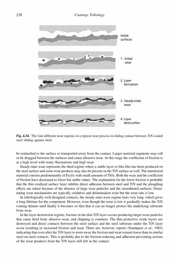
be reattached to the surface or transported away from the contact. Larger material segments may rollor be dragged between the surfaces and cause abrasive wear. At this stage the coefficient of friction isat a high level with many fluctuations and high wear.
Steady-state wear represents the third regime where a stable layer or thin film has been produced onthe steel surface and some wear products may also be present on the TiN surface as well. The transferredmaterial consists predominantly of Fe2O3 with small amounts of TiO2. Both the wear and the coefficientof friction have decreased to lower but stable values. The explanation for the lower friction is probablythat the thin oxidized surface layer inhibits direct adhesion between steel and TiN and the ploughingeffects are minor because of the absence of large wear particles and the smoothened surfaces. Domi-nating wear mechanisms are typically oxidative and delamination wear but the wear rate is low.
In tribologically well-designed contacts, the steady-state wear regime lasts very long, which givesa long lifetime for the component. However, even though the wear is low it gradually makes the TiNcoating thinner until finally it becomes so thin that it can no longer protect the underlying substratefrom wear.
In the layer destruction regime, fracture in the thin TiN layer occurs producing larger wear particlesthat cause third body abrasive wear, and chipping is common. The thin protective oxide layers aredestroyed and direct contacts between the steel surface and the steel substrate under the TiN layeroccur resulting in increased friction and wear. There are, however, reports (Sundquist et al., 1983)indicating that even after the TiN layer is worn away the friction and wear remain lower than in similarsteel-on-steel contacts. This is probably due to the friction-reducing and adhesion-preventing actionsof the wear products from the TiN layer still left in the contact.
Fig. 4.34. The four different wear regimes in a typical wear process in sliding contact between TiN coatedsteel sliding against steel.
228 Coatings Tribology
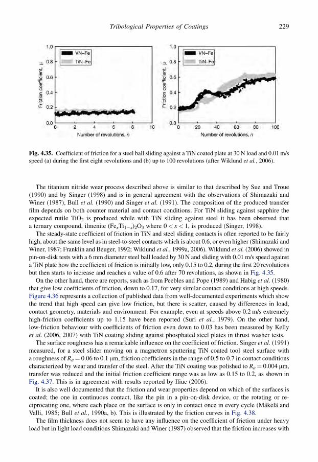
The titanium nitride wear process described above is similar to that described by Sue and Troue(1990) and by Singer (1998) and is in general agreement with the observations of Shimazaki andWiner (1987), Bull et al. (1990) and Singer et al. (1991). The composition of the produced transferfilm depends on both counter material and contact conditions. For TiN sliding against sapphire theexpected rutile TiO2 is produced while with TiN sliding against steel it has been observed thata ternary compound, ilmenite (FexTi1�x)2O3 where 0< x< 1, is produced (Singer, 1998).
The steady-state coefficient of friction in TiN and steel sliding contacts is often reported to be fairlyhigh, about the same level as in steel-to-steel contacts which is about 0.6, or even higher (Shimazaki andWiner, 1987; Franklin and Beuger, 1992; Wiklund et al., 1999a, 2006). Wiklund et al. (2006) showed inpin-on-disk tests with a 6 mm diameter steel ball loaded by 30 N and sliding with 0.01 m/s speed againsta TiN plate how the coefficient of friction is initially low, only 0.15 to 0.2, during the first 20 revolutionsbut then starts to increase and reaches a value of 0.6 after 70 revolutions, as shown in Fig. 4.35.
On the other hand, there are reports, such as from Peebles and Pope (1989) and Habig et al. (1980)that give low coefficients of friction, down to 0.17, for very similar contact conditions at high speeds.Figure 4.36 represents a collection of published data from well-documented experiments which showthe trend that high speed can give low friction, but there is scatter, caused by differences in load,contact geometry, materials and environment. For example, even at speeds above 0.2 m/s extremelyhigh-friction coefficients up to 1.15 have been reported (Suri et al., 1979). On the other hand,low-friction behaviour with coefficients of friction even down to 0.03 has been measured by Kellyet al. (2006, 2007) with TiN coating sliding against phosphated steel plates in thrust washer tests.
The surface roughness has a remarkable influence on the coefficient of friction. Singer et al. (1991)measured, for a steel slider moving on a magnetron sputtering TiN coated tool steel surface witha roughness of Ra¼ 0.06 to 0.1 mm, friction coefficients in the range of 0.5 to 0.7 in contact conditionscharacterized by wear and transfer of the steel. After the TiN coating was polished to Ra¼ 0.004 mm,transfer was reduced and the initial friction coefficient range was as low as 0.15 to 0.2, as shown inFig. 4.37. This is in agreement with results reported by Iliuc (2006).
It is also well documented that the friction and wear properties depend on which of the surfaces iscoated; the one in continuous contact, like the pin in a pin-on-disk device, or the rotating or re-ciprocating one, where each place on the surface is only in contact once in every cycle (Makela andValli, 1985; Bull et al., 1990a, b). This is illustrated by the friction curves in Fig. 4.38.
The film thickness does not seem to have any influence on the coefficient of friction under heavyload but in light load conditions Shimazaki and Winer (1987) observed that the friction increases with
Fig. 4.35. Coefficient of friction for a steel ball sliding against a TiN coated plate at 30 N load and 0.01 m/sspeed (a) during the first eight revolutions and (b) up to 100 revolutions (after Wiklund et al., 2006).
229Tribological Properties of Coatings

the absolute value of film thickness. According to Peebles and Pope (1989) neither the coefficient offriction nor the wear should be dependent on the contact stress, in the range of 60 to 1060 MPa.
The microstructure of the titanium nitride coating and thus the coating method has an influence onthe tribological properties of the coating. This has been well demonstrated by Bull et al. (1990). Theyshow that the adhesive wear of the TiN coating is determined by two factors, the openness of the
Fig. 4.37. Friction coefficient as a function of pass number for a hardened AISI 52100 12.7 mm diameter steelball sliding on TiN coated M2 tool steel with as-received and polished surfaces at a speed of 0.1 m/s, a load of10 N and with a relative humidity of 30%. Vertical lines indicate stick slip (data from Singer et al., 1991).
Fig. 4.36. Coefficients of friction measured at different sliding speeds for a steel slider on a TiN coatedsubstrate collected from the literature.
230 Coatings Tribology
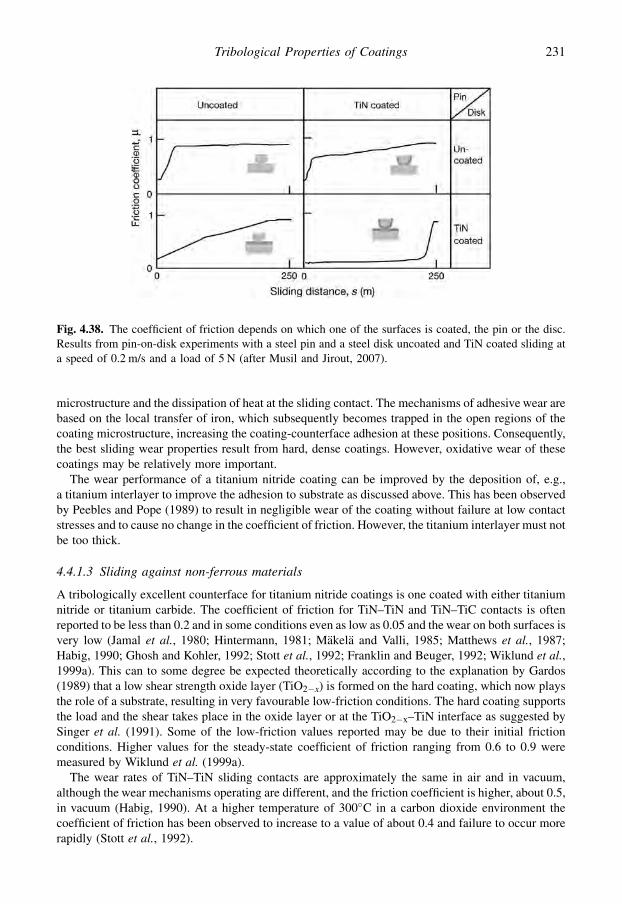
microstructure and the dissipation of heat at the sliding contact. The mechanisms of adhesive wear arebased on the local transfer of iron, which subsequently becomes trapped in the open regions of thecoating microstructure, increasing the coating-counterface adhesion at these positions. Consequently,the best sliding wear properties result from hard, dense coatings. However, oxidative wear of thesecoatings may be relatively more important.
The wear performance of a titanium nitride coating can be improved by the deposition of, e.g.,a titanium interlayer to improve the adhesion to substrate as discussed above. This has been observedby Peebles and Pope (1989) to result in negligible wear of the coating without failure at low contactstresses and to cause no change in the coefficient of friction. However, the titanium interlayer must notbe too thick.
4.4.1.3 Sliding against non-ferrous materials
A tribologically excellent counterface for titanium nitride coatings is one coated with either titaniumnitride or titanium carbide. The coefficient of friction for TiN–TiN and TiN–TiC contacts is oftenreported to be less than 0.2 and in some conditions even as low as 0.05 and the wear on both surfaces isvery low (Jamal et al., 1980; Hintermann, 1981; Makela and Valli, 1985; Matthews et al., 1987;Habig, 1990; Ghosh and Kohler, 1992; Stott et al., 1992; Franklin and Beuger, 1992; Wiklund et al.,1999a). This can to some degree be expected theoretically according to the explanation by Gardos(1989) that a low shear strength oxide layer (TiO2�x) is formed on the hard coating, which now playsthe role of a substrate, resulting in very favourable low-friction conditions. The hard coating supportsthe load and the shear takes place in the oxide layer or at the TiO2�x–TiN interface as suggested bySinger et al. (1991). Some of the low-friction values reported may be due to their initial frictionconditions. Higher values for the steady-state coefficient of friction ranging from 0.6 to 0.9 weremeasured by Wiklund et al. (1999a).
The wear rates of TiN–TiN sliding contacts are approximately the same in air and in vacuum,although the wear mechanisms operating are different, and the friction coefficient is higher, about 0.5,in vacuum (Habig, 1990). At a higher temperature of 300�C in a carbon dioxide environment thecoefficient of friction has been observed to increase to a value of about 0.4 and failure to occur morerapidly (Stott et al., 1992).
Fig. 4.38. The coefficient of friction depends on which one of the surfaces is coated, the pin or the disc.Results from pin-on-disk experiments with a steel pin and a steel disk uncoated and TiN coated sliding ata speed of 0.2 m/s and a load of 5 N (after Musil and Jirout, 2007).
231Tribological Properties of Coatings

Jamal et al. (1980) have found that other titanium-based variations of the counterface coating canproduce favourable tribological conditions, such as TiC/Ti, TiC2N/Ti and Tiþ TiC/Al. Tribologicallyless favourable counterfaces are titanium, aluminium (Jamal et al., 1980), copper (Matthews et al.,1987), alumina (Huq and Celis, 1997) and chromium and stainless steel (Wiklund et al., 2006).A nickel ball as counterface, on the other hand, resulted in very stable sliding with a coefficient offriction of 0.35 in pin-on-disk tests by Wiklund et al. (2006).
Very low-friction coefficients were reported from pin-on-disk tests with single-crystal sapphireballs of various diameters sliding against polished TiN coatings at speeds of 0.02 to 0.08 m/s and loadsof 2 to 10 N. The initial coefficient of friction was as low as 0.05 and then slowly increased to 0.1 to0.15 after about 1500 revolutions (Singer et al., 1991). The very smooth sliding surfaces used seem tobe one explanation for the low friction. The higher friction coefficient corresponded to more debris inthe wear track.
Titanium nitride in sliding contact with graphite gives reasonably low wear but when the coatinggets thin spalling occurs, which results in a very significant increase in wear rate, owing to thepresence of hard, abrasive third bodies between the contacts as shown by Kennedy et al. (1990) in sealcontact experiments.
The ambient humidity can considerably influence the tribological properties in sliding TiN con-tacts. This is well illustrated by measurements carried out in reciprocating fretting contacts, witha 10 mm diameter corundum ball of surface roughness 0.2 mm sliding at 10 Hz, 1 N load and 100 mmsliding distance reported by Zhang et al. (2003a). They record a coefficient of friction of 0.15 at 90%relative humidity, 0.2 at 50% RH and as high as 0.8 at 10% RH. However, the wear rate was the same,20 $ 10�6 $ mm3/Nm, for all three humilities. The friction results are very similar to the results fromfretting tests of an Al2O3 ball sliding against a TiN plate in the same humidity range measured byKlafke (2004c). However, Klafke observed a slight decrease in wear with increasing humidity.
4.4.1.4 Abrasive wear resistance
The wear resistance against abrasion of steel components can be considerably improved by applyinga 2 to 6 mm thick TiN coating on the surface (Sirvio et al., 1982; Rickerby and Burnett, 1987; Mattheset al., 1990a; Ghosh and Kohler, 1992; Bromark, 1996; Batista et al., 2002). The high hardness isindeed one parameter which improves the abrasive wear resistance. The initial surface roughnessinfluences the wear resistance so that smoother surfaces result in less wear (Sirvio et al., 1982).Improved toughness and abrasion resistance can be produced by thicker films with a multilayerstructure with titanium and titanium nitride layers, and with a duplex structure where the TiN film isdeposited on plasma-nitrided surfaces (Leyland, 1991; Leyland and Matthews, 1993; Batista et al.,2002).
The load-carrying capacity of the coating/substrate system is important, as has been pointed outby Rickerby and Burnett (1987). Under mild abrasive wear they found that thin coatings eventuallyfail by localized detachment of the film at the intersections of the plastic grooves formed by theabrasive particles. Thicker coatings, on the other hand, have the ability to support the contact stresseselastically and degrade by a microchipping or polishing mechanism with little or no deformation ofthe underlying substrate, as shown in Fig. 4.39. However, in thicker titanium nitride coatings dif-ferences in wear rate have been observed related to microstructural effects. These can be attributedto a decrease in coating density and increasing grain size with increasing thickness (Burnett andRickerby, 1987a, b). Under severe abrasive wear, thick coatings fail mainly by a cohesive fracturemechanism.
The abrasive wear resistance of titanium nitride coatings can be further improved by introducingtitanium either as interlayers or dispersed within the bulk of the coating and this can also promotegood adhesion (Matthews, 1980). Some techniques, especially arc evaporation, produce discretedroplets of titanium in the film. At low stresses the presence of metallic titanium may have a beneficial
232 Coatings Tribology

effect by reducing the internal stresses and improving the toughness. At higher contact stresses thepenetration of the metallic titanium droplets in the coating by the abrasive particles may result inincreased tearing and abrasion between the abrasive and the coating and in increased wear.
4.4.1.5 Erosive wear resistance
The erosive wear resistance of steel coated by a layer of 1 to 10 mm titanium nitride is considerablybetter than for uncoated steel. It has been shown that the wear resistance depends on the hardness ofthe coating/substrate composite system, the shape of the eroding particles and the angle of bom-bardment (Burnett and Rickerby, 1988; Hedenquist and Olsson, 1990; Rogers et al., 1992; Iwai et al.,2001). Higher composite hardness, i.e. the hardness of the coating/substrate combination, in generalgives reduced erosive wear, as shown in Fig. 4.40.
Fig. 4.39. For hard coatings on softer substrates the substrate (a) deforms elastically with thin coatings but(b) is undeformed with thick coatings, because the coating can carry the load.
Fig. 4.40. Erosion tests show that the erosion rate decreases (a) with increasing coating thickness, h, andsubstrate hardness, HV, and (b) with increasing surface composite hardness (after Hedenquist and Olsson,1990).
233Tribological Properties of Coatings
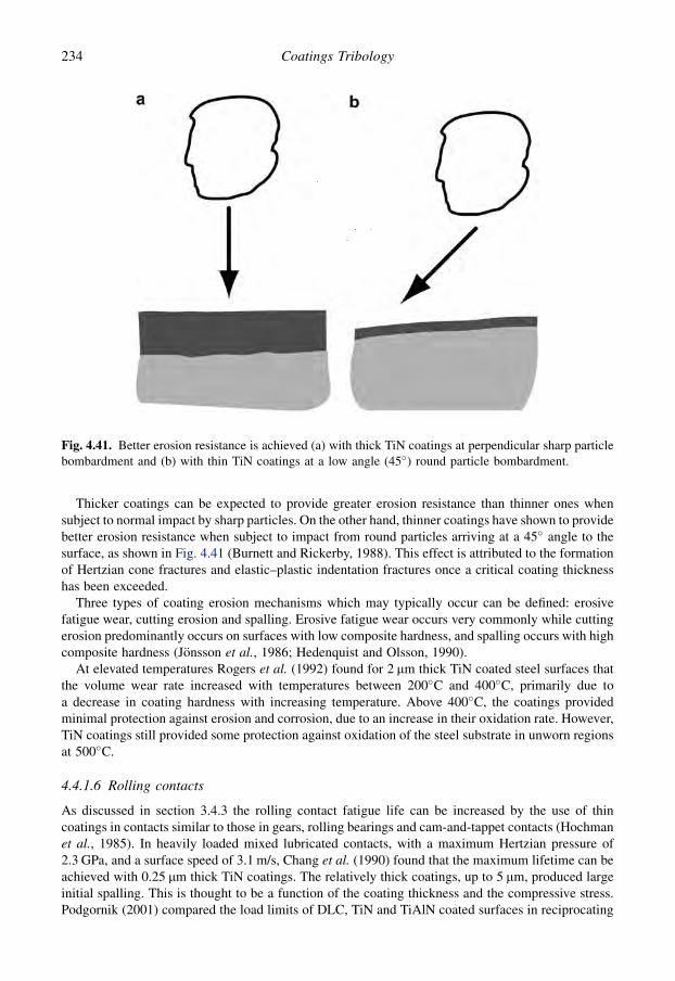
Thicker coatings can be expected to provide greater erosion resistance than thinner ones whensubject to normal impact by sharp particles. On the other hand, thinner coatings have shown to providebetter erosion resistance when subject to impact from round particles arriving at a 45� angle to thesurface, as shown in Fig. 4.41 (Burnett and Rickerby, 1988). This effect is attributed to the formationof Hertzian cone fractures and elastic–plastic indentation fractures once a critical coating thicknesshas been exceeded.
Three types of coating erosion mechanisms which may typically occur can be defined: erosivefatigue wear, cutting erosion and spalling. Erosive fatigue wear occurs very commonly while cuttingerosion predominantly occurs on surfaces with low composite hardness, and spalling occurs with highcomposite hardness (Jonsson et al., 1986; Hedenquist and Olsson, 1990).
At elevated temperatures Rogers et al. (1992) found for 2 mm thick TiN coated steel surfaces thatthe volume wear rate increased with temperatures between 200�C and 400�C, primarily due toa decrease in coating hardness with increasing temperature. Above 400�C, the coatings providedminimal protection against erosion and corrosion, due to an increase in their oxidation rate. However,TiN coatings still provided some protection against oxidation of the steel substrate in unworn regionsat 500�C.
4.4.1.6 Rolling contacts
As discussed in section 3.4.3 the rolling contact fatigue life can be increased by the use of thincoatings in contacts similar to those in gears, rolling bearings and cam-and-tappet contacts (Hochmanet al., 1985). In heavily loaded mixed lubricated contacts, with a maximum Hertzian pressure of2.3 GPa, and a surface speed of 3.1 m/s, Chang et al. (1990) found that the maximum lifetime can beachieved with 0.25 mm thick TiN coatings. The relatively thick coatings, up to 5 mm, produced largeinitial spalling. This is thought to be a function of the coating thickness and the compressive stress.Podgornik (2001) compared the load limits of DLC, TiN and TiAlN coated surfaces in reciprocating
Fig. 4.41. Better erosion resistance is achieved (a) with thick TiN coatings at perpendicular sharp particlebombardment and (b) with thin TiN coatings at a low angle (45�) round particle bombardment.
234 Coatings Tribology

sliding and rolling tests with a speed of 0.1 m/s and load of 10 N and found that TiN could take 3 to 5times higher loads compared to TiAlN in similar conditions but the DLC coated surface could takeeven a 30% higher load than TiN without failure.
In a comparison of a steel surface with TiN, CrN and WC/C coated surfaces Remigiusz et al. (2004)received poor lifetime results in lubricated rolling tests for both TiN and CrN coatings compared withthe other two. Thus the experience documented in the literature is not entirely clear. There seems to beevidence that the rolling contact fatigue life can be increased by using TiN coated steel surfaces. Onthe other hand, the stress and strain conditions are so complex and it is so difficult to optimize thecoating dimensions and mechanical properties, so poor results can easily be encountered.
4.4.1.7 Cutting contacts
Titanium nitride coatings deposited on high-speed steel (HSS) by physical vapour deposition havesuccessfully been used in metal cutting applications for a number of years. It has been documented inseveral experimental reports (Sundquist et al., 1983; Matthews, 1989; Posti and Nieminen, 1989a, b;Harju et al., 1990; Spur et al., 1990; Kowstubhan and Philip, 1991; Bromark, 1996; Grzesik, 2000)that the tool life in cutting can be increased by even orders of magnitude, by TiN coated HSS inserts.This is due to a unique combination of properties of the TiN coated tool, such as sufficient adhesion tothe substrate, high hot hardness, high wear resistance and an ability to improve the contact conditionsat the cutting edge (Hedenqvist et al., 1990b). Equations for the prediction of tool life of TiN coatedtools have been developed by Kowstubhan and Philip (1991).
The increased wear resistance of the tool is mainly achieved by the high hardness of the TiNcoating, 2000 to 2500 HV, which gives a good resistance to abrasive wear, and the high chemicalstability, resulting in a high resistance to solution wear. The oxidation of the TiN surface is slow attemperatures below 600�C. The good adhesion to the substrate can inhibit interfacial cracking evenwhen the substrate is plastically deformed due to surface stresses. An increased production rate can beachieved in cutting with TiN coated tools because of increased cutting speeds and feeds. Decreasedcutting temperatures have been reported, which probably is due more to improved contact conditionsand reduced friction than to the TiN coating acting as a thermal barrier (Hedenqvist et al., 1990b). Ithas been shown that even when the coating is locally worn through, the remaining coating stillprotects the substrate and is capable of carrying the full load of the chip without collapsing. Thisapplies even on reground tools, where some benefit still derives from the remaining side-face coating.
The optimum thickness of the coating depends on the cutting methods, as shown by Posti andNieminen (1989a). In continuous cutting methods, like turning, a thicker coating gives a longer toollife. Good results were achieved with a coating thickness of 6 mm. In discontinuous cutting, likeplaning, on the other hand, an optimum coating thickness of 2 to 3 mm was observed as shown inFig. 4.42. Both thicker and thinner coatings reduced the lifetime of the tool. Thin coatings are wornout faster by mechanical wear and with thicker coatings local detachment occurs due to the reducedflexibility of the hard coating on the softer substrate.
In dry machining conditions the flank wear can be reduced with the aid of chlorine ion implantationin titanium-based ceramic coatings (Aizawa et al., 2005). Titanium mono-oxide is formed in situ toact as a plastically deforming tribofilm. The tribofilm works as a lubricious buffer between workmaterials and tools to reduce the wear and friction. Dry drilling tests have shown that the combinationof MoSx with TiN in the deposition process resulting in a composite TiN–MoSx coating, can increasethe average drill lifetime by more than one-third (Cosemans et al., 2003). The MoSx componentreduces the friction.
Similar remarkable improvements in lifetime have not been achieved in wood cutting as with TiNcoated tools in metal cutting. However, Usenius et al. (2004c) noticed some improvements, e.g. a 20%reduced rake face wear in cutting of spruce with high-speed steel TiN coated tools compared withuncoated tools and 50% reduced rake face wear when sawing hardboard.
235Tribological Properties of Coatings

4.4.2 Other nitride coatings
Even though titanium nitride coatings have a very strong market position there have been a variety ofother nitride coatings developed for tribological applications. In addition to titanium aluminiumnitride (Ti,Al)N, and boron nitride (BN), other nitrides have been studied, such as chromium nitride(CrN), carbon nitride (CN), vanadium nitride (VN), hafnium nitride (HfN), zirconium nitride (ZrN),as well as multicomponent nitrides like Ti(B,N), Ti(B,C,N), Ti(C,N), (Ti,Nb)N, (Ti,Zr)N, (Ti,V)N,(B,C)N and (Zr,Hf)N. However, for many of these there is only a very limited amount of informationavailable about their tribological properties and the tribological mechanisms are seldom explained.The main uses of these other nitride coatings have been in applications such as cutting tools, turbineblades, forming tools and pump components.
Recently, the cubic form of boron nitride (c-BN) has attracted a great deal of interest because of itsextreme hardness, chemical inertness, high thermal conductivity and transparency. The different PVDand CVD techniques available for the deposition of c-BN have been reviewed by Karim et al. (1991),Veprek (1999) and Erdemir and Donnet (2001).
4.4.2.1 Nitride coatings in sliding contacts
The nitrides are generally hard coatings with a typical microhardness in the range of 2 to 4 GPa. Insliding contacts with steel their coefficients of friction are often fairly high, in the range of 0.6 to 0.9.
Fig. 4.42. TiN coated ASP 30 tool lifetimes in planing tests as a function of coating thickness (data fromPosti and Nieminen, 1989a).
236 Coatings Tribology

Here boron nitride forms an exception for which coefficients of friction down to 0.05 have beenmeasured for the hexagonal phase.
In sliding pin-on-disk tests with a steel pin sliding on a titanium aluminium nitride (Ti,Al)N coatingon a steel substrate with a speed of 0.1 m/s and a load of 10 N, Ronkainen et al. (1990a) measuredcoefficients of friction as high as 0.7 to 0.9, with pin wear rates of 3 to 5 $ 10�6 mm3/Nm and diskwear rates of 20 to 60 $ 10�6 mm3/Nm. Wear debris and transferred layers of reaction products wereobserved. In comparison with the wear of TiN, Podgornik (2001) measured in a pin-on-disk test with0.1 m/s speed and 60 N load and sliding against a steel ball that (Ti,Al)N showed about 10% lowerwear rate than TiN. In rolling tests the same (Ti,Al)N had a considerably lower load-carrying capacity,the load limit was only 10 to 30% of that of TiN depending on the substrate hardness.
Roos et al. (1990) found in a comparative test that a ball coated with (Ti,Al)N was worn twice asmuch as a ball coated with TiN in a pin-on-disk test at speeds of 0.4 m/s and loads of 4 N. Coll et al.(1992) studied the influence of the titanium–aluminium ratio in (Ti,Al)N coatings and found inpin-on-disk tests, with a speed of 0.5 m/s, a load of 2 N and a steel counterface, a coefficient of frictionof 0.74 and a wear rate of 0.092 $ 10�6 mm3/Nm for a Ti:Al ratio of 53:47 wt%. The coefficient offriction decreased to 0.54 and the wear rate to 0.056 $ 10�6 mm3/Nm with a lower aluminium contentof Ti:Al¼ 83:17 wt%. The coefficient of friction decreased with increasing speed and was as low as0.37 at 5 m/s. Increasing wear with higher aluminium content in the coating has also been found inpin-on-disk tests with an aluminium oxide (corundum) ball as counterface (Vancoille et al., 1993a). Infretting tests Klafke (2004c) measured coefficients of friction of about 0.7 in dry air of 3% RH andnormal 47% RH air when sliding against an Al2O3 ball while the increase of the humidity to 100%dropped the coefficient of friction to 0.5.
Boron nitride (BN) coatings on different substrates and in different environments have beenstudied by Miyoshi (1989a). He describes the ion beam-deposited coatings as mainly amorphouscontaining a small amount of hexagonal BN. The boron nitride films deformed elastically andplastically and surface films on the coatings affected their tribological behaviour. In very slow singlepass contacts with a speed of 0.0002 m/s he measured very low coefficients of friction from 0.05 to0.2 for a diamond stylus sliding on a boron nitride coating and almost equally low-friction co-efficients from 0.08 to 0.12 for a steel pin sliding on the BN coating. Similar results for diamondsliding on BN have been reported by Elena et al. (1988). The presence of the BN film decreasesadhesion and plastic deformation in the contact and accordingly the friction. Similarly, low values forthe friction in vacuum have been measured by Miyoshi (1989a). The sliding combination of a 80 mNlightly loaded textured BN slider sliding with 0.5 m/s in 50% RH against a DLC coated silicondisk resulted in a higher coefficient of friction of 0.41 and a slider wear rate of 0.01 $ 10�6 mm3/Nm(Zhou et al., 2000).
Boron nitride with a cubic crystal structure (c-BN) is an extremely hard material. It is the hardestknown material after diamond and thus a potential candidate for wear-resistant coating applications.Unlike diamond, it does not dissolve in or interact with Fe-based alloys, and thus can be used tomachine ferrous materials. It has a high melting point, excellent thermal and chemical stability andthus excellent wear and oxidation resistant properties at high temperatures. Tribological studies haveshown that the performance of c-BN is highly dependent on the environment and the counterfacematerial. The wider commercial use of c-BN is limited by its film thickness, high internal stresses,poor adhesion to the substrate and poor reproducibility of structure and properties (Erdemir andDonnet, 2001; Koskilinna, 2007).
Cubic boron nitride coatings have, in general, poor adhesion to various substrates but this can beconsiderably improved by applying an interlayer such as silicon nitride (Inagawa et al., 1989). Theyfound that in a sliding ring on disk contact loaded at 10 N the coefficient of friction was 0.35 but ata low pressure of 1.7 $ 1013 Pa and a high temperature of 400�C it was extremely low, only 0.02. Thec-BN film had a thickness of 1.5 mm and microhardness of 5.5 to 6.3 GPa HV. Good results have alsobeen achieved with a titanium interlayer.
237Tribological Properties of Coatings

Watanabe et al. (1991) and Miyake et al. (1992) have compared the different forms of BN filmsdeposited on silicon wafers by using a reciprocating friction and wear tester and found that the tri-bological properties of cubic boron nitride are superior to amorphous boron nitride (a-BN) andhexagonal boron nitride (h-BN). The steady-state coefficient of friction for a-BN and h-BN was in therange of 0.8 to 1.0 while it was about 0.3 for c-BN as shown in Fig. 4.43. In a continuously slidingball-on-disk test with 1 N load, 0.01 m/s speed and 40–50% RH Watanabe et al. (2004) measureda rapidly increasing coefficient of friction up to 0.6 and 0.7 after only some 10 to 50 revolutions withc-BN sliding against itself and against a-BN. With c-BN and a-BN sliding against a DLC coating thecoefficient of friction reached a steady-state value of about 0.14 and no damage was observed.
Theoretical calculations have predicted that a new form of carbon nitride (C3N4), the cubic betaphase, would have very low compressibility and extremely high hardness exceeding that of naturaldiamond. This has attracted many researchers to develop new methods to synthesize crystalline C3N4
but this has not yet been fully realized. However, many groups have been able to produce amorphousC3N4 coatings with very good tribological performance even if they are softer than diamond. Due tothe difference in the deposition methods the amorphous C–N coatings exhibit large variationsin mechanical and tribological properties (Erdemir and Donnet, 2001). High hardness of amorphousC–N coatings in the range of 15 to 50 GPa has been reported.
Based on results from a ball-on-disk test with Si3N4, balls sliding against 100 nm thick CNx
coatings deposited on silicon wafers sliding in the load range of 80 to 750 mN and speed range of0.004 to 0.4 m/s in different environments Kato et al. (2003) could conclude the following. Thecoefficient of friction was high, 0.2 to 0.4, in air and O2, but low, 0.01 to 0.1 in N2, in CO2 and invacuum. The lowest coefficient of friction, less than 0.01, was measured in N2. The wear rates of theCNx coatings were in the range of 0.001 to 10 $ 10�6 mm3/Nm depending on the environment. Themajor running-in wear mechanism of CNx in abrasive sliding against hard asperities was low-cyclefatigue which generated thin flaky wear particles of nanometre size (Wang and Kato, 2003b, c). It isinteresting that good wear resistance properties have been achieved with extremely thin, only 1 nm
Fig. 4.43. The coefficient of friction as a function of number of reciprocating cycles for cubic (c-BN),amorphous (a-BN) and hexagonal (h-BN) boron nitride coatings on silicon substrates sliding againsta 6.35 diameter steel ball in reciprocating pin-on-flat tests with a speed of 0.0017 m/s, load of 5 N, strokelength of 0.01 m and relative humidity of 50 to 60% (after Miyake et al., 1992).
238 Coatings Tribology

thick, CN coatings on magnetic disks sliding against a friction force microscope (FFM) diamond tipwith a sliding length of 5 mm and up to 2000 sliding cycles (Wang et al., 2005).
Chromium–nitrogen (Cr–N) compound coatings have been developed by the PVD method for thepurpose of achieving superior properties to electrodeposited chrome. The tribological properties ofvarious Cr–N coatings were studied by Bull and Rickerby (1990a) with a pin-on-disk tribotester ata speed of 0.1 m/s and a load of 2.75 N. They found that the coefficient of friction for a steel ballsliding on a Cr–N coating on a steel substrate was 0.6 to 0.8 and the wear was not particularly low,being in the range 1 to 100 $ 10�6 mm3/Nm for the coated disk and 0.1 to 10 $ 10�6 mm3/Nm for theball. They noticed that as the hardness of the coating increases, plastic deformation in the substrate isreduced and this leads to a decrease in the disk wear rate until it is comparable with that of a similartitanium nitride coated disc. In this situation a visible flat is formed on the ball and the wear of the ballmaterial dominates. A considerable transfer of material from the disk to the ball was observed.
At a higher load of 10 N, same speed but with a ceramic Al2O3 ball as the counterface Tuszynskiet al. (2003) measured a similar high coefficient of friction of 0.8 but the wear rate of the coated diskwas only 0.05 $ 10�6 mm3/Nm. The wear resistance was two orders of magnitude better than that ofTiN coatings in the same conditions. The CrN coatings improved the abrasive wear resistance con-siderably, as found also by Leyland et al. (1993). In lubricated sliding the CrN coating has been foundto considerably improve the scuffing wear resistance compared with that of steel surfaces (Remigiuszet al., 2004).
Vanadium nitride (VN) is a ceramic compound closely related to TiN. Quantum calculations haveshown that it should have very different adhesive properties against pure iron compared to TiN(Wiklund, et al., 2006). Wiklund et al. compared the friction properties of VN and TiN in a ball-on-disk test with 3 mm radius balls sliding at 30 N load and 0.01 m/s speed against different ball ma-terials. When sliding against steel and chromium balls both coatings showed the same friction be-haviour, with a coefficient of friction starting initially at 0.15 but soon increasing to the level of 0.6(see Fig. 4.35). With pure nickel balls the coefficient of friction for VN was 0.3 while it was slightlyhigher, 0.35, for the TiN coating. With stainless steel balls both coatings very quickly reached a co-efficient of friction of 0.6 but there were indications that VN had better galling protection properties.
Zirconium nitride (ZrN) coatings have been of interest since some reports show that they havebetter mechanical, wear and corrosion properties than TiN coatings. Thus they have been increasinglyused in industry for specific applications such as coatings for tools for machining non-ferrous ma-terials (aluminium and nickel alloys) and thermal barrier coatings in microelectronics, as well as fordecorative coatings (Atar et al., 2004).
The tribological properties of titanium boron nitride Ti(B,N) coatings produced by ionization-assisted electron beam PVD and by rf magnetron sputtering have been studied by Ronkainen et al.(1990a). The coefficient of friction against M50 steel was in the range of 0.6 to 0.9, the pin wear0.8 $ 10�6 mm3/Nm and the disk wear 15 $ 10�6 mm3/Nm measured with a pin-on-disk test at a speedof 0.1 m/s and a load of 10 N. The sliding wear resistance is of the same order as for titanium nitrideand slightly better than for titanium aluminium nitride coatings in the same contact conditions. Whitepowder-like wear debris and transferred layers of reaction products on the surfaces were observed.The Ti(B,N) coatings had a thickness 4 to 8 mm and a microhardness of 2 to 3.5 GPa. The hardness,elastic modulus and also the internal residual stresses increase with the relative boron content in thecoating (Kullmer et al., 2003).
The tribological properties of titanium carbonitride Ti(C,N) are better or similar to titanium nitridedepending on the contact conditions. The residual compressive stresses in Ti(C,N) coatings canbe very high, values up to about 7 GPa have been measured for 4 mm thick coatings (Zoestbergen andDe Hosson, 2002). In abrasive wear tests as well as in cross-cylinder tests Ti(C,N) coatings haveshown a better wear resistance compared to TiN coatings but the result was the other way round inreciprocating and ball-on-disk wear tests (Ghosh and Kohler, 1992; Konig and Kammermeier, 1992;Tuszynski et al., 2003). In a comparison of tribological properties of TiN, (Ti,Al)N, (Ti,Nb)N, and
239Tribological Properties of Coatings

Ti(C,N) deposited on high-speed steel and sliding against aluminium oxide (corundum) Vancoilleet al. (1993b) found that titanium carbonitride coatings were the most promising at a speed of 0.1 m/sand a load of 5 N. The steady-state coefficient of friction was in the range of 0.1 to 0.4 while for TiN itwas 0.8 to 1.2, for (Ti,Nb)N it was 0.8 to 1.4 and for (Ti,Al)N it was 1.0 to 1.4. The wear was also lowfor Ti(C,N). The tribological behaviour of Ti(C,N) coatings in fretting tests has been very similar tothat of TiN (Klafke, 2004c; Liskiewicz et al., 2004). In a comparison of six different commercialTi(C,N) coatings Bull et al. (2003a, b) found that both the friction and wear properties varied a lot andwere critically dependent on the coating structure produced by the different deposition processes.Coating adhesion was improved by the use of a thin TiN interlayer.
4.4.2.2 Nitride coatings in metal cutting contacts
Major improvements in the lifetime of cutting tools have been achieved by coating them with a ti-tanium aluminium nitride layer. The fundamental advantage of (Ti,Al)N is its characteristic offorming a dense, highly adhesive, protective Al2O3 film on its surface when heated, preventing dif-fusion of the coating material into the workpiece. A second advantage for machining applications is itslow thermal conductivity. Considerably more heat is dissipated via chip removal. This enables cor-respondingly higher cutting speeds to be selected, since the thermal loading on the substrate is lower(Leyendecker et al., 1989).
Finding the optimal coating thickness is important for cutting tool performance. An increase in thecoating thickness usually deteriorates the coating mechanical strength. The typical cone-shaped columngrowth leads to increased grain size at the top surface for thicker coatings. Due to the coarser micro-structure at the top surface, it can be expected that a diminishing of the film mechanical properties occurswith thicker coatings. On the other hand, thicker coatings lead to higher effective cutting edge radii,thus generating lower stresses on the cutting edge. The substrate is better protected against abrasive wearand thermal loads occurring during the cutting process with thicker coatings. Based on FEM calculationsand with milling tests Bouzakis et al. (2003) investigated (Ti46,Al54)N coated cemented carbide insertsin the thickness range of 2 to 10 mm and demonstrated the enhanced cutting performance of thickcoatings especially over 6 mm, in comparison to thinner ones, as shown in Fig. 4.44.
It is relevant to compare the properties of (Ti,Al)N coated tools with TiN coated tools because thelatter represents the commonly used commercially available state-of-the-art level. In turning tests onsteel with (Ti,Al)N coated high-speed steel inserts the tool lifetime has been increased by two to threetimes compared with TiN (Molarius et al., 1987; Leyendecker et al., 1989; Ronkainen et al., 1991b;Byeli et al., 1992). However, the lifetime was only half that of TiN when cutting aluminium alloy asshown in Fig. 4.45 (Ronkainen et al., 1991b). A superior performance of (Ti,Al)N coated drills wasalso reported by Leyendecker et al. (1989) who drilled 12 times as many holes in grey cast iron aswas possible with a TiN coating before tool failure. When drilling in an aluminium alloy the tool lifewas increased by three times (Leyendecker et al., 1989) and when drilling in steel by two times(Ronkainen et al., 1991b) compared to TiN coated drills. Improvements in lifetimes of two to fivetimes for (Ti,Al)N coated hobs in gear production tests compared to uncoated hobs has beendemonstrated by Zlatanovic and Munz (1990).
The improvements in tool lifetimes by several other varieties of nitrides have also beeninvestigated: zirconium nitride (ZrN) by Molarius et al. (1987), hafnium nitride (HfN) by Harju et al.(1990), titanium boron nitride Ti(B,N) by Ronkainen et al. (1991a), titanium vanadium nitride(Ti,V)N by Knotek et al. (1990a, 1992b), titanium zirconium nitride (Ti,Zr)N by Konig and Fritsch(1992), titanium niobium nitride (Ti,Nb)N by Roos et al. (1990) and chromium nitride in wood cuttingby Beer et al. (2003) and Noveau et al. (2005). The general result is that the lifetimes of tools withthese coatings have often been about the same as or slightly better than TiN coated tools. However, indrilling tests in steel with a (Ti,Nb)N coated tool a lifetime of three times that of TiN coatings has beenreported.
240 Coatings Tribology
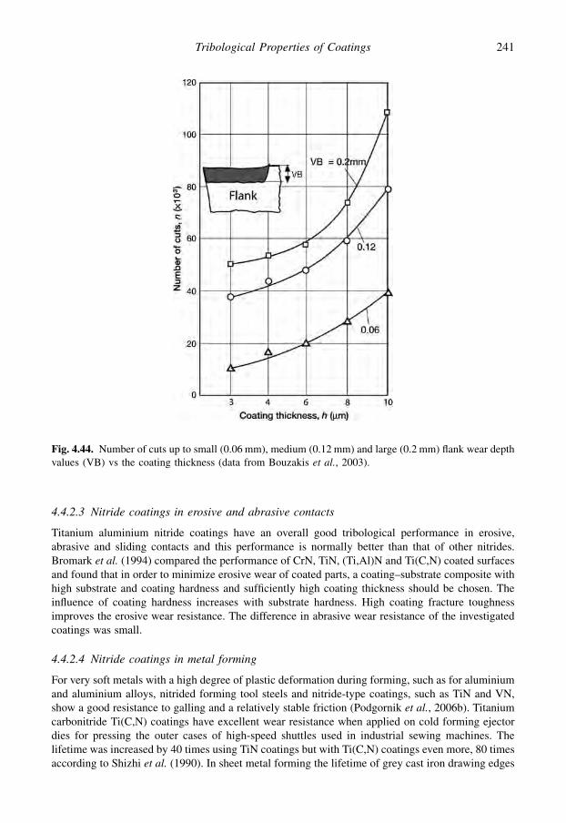
4.4.2.3 Nitride coatings in erosive and abrasive contacts
Titanium aluminium nitride coatings have an overall good tribological performance in erosive,abrasive and sliding contacts and this performance is normally better than that of other nitrides.Bromark et al. (1994) compared the performance of CrN, TiN, (Ti,Al)N and Ti(C,N) coated surfacesand found that in order to minimize erosive wear of coated parts, a coating–substrate composite withhigh substrate and coating hardness and sufficiently high coating thickness should be chosen. Theinfluence of coating hardness increases with substrate hardness. High coating fracture toughnessimproves the erosive wear resistance. The difference in abrasive wear resistance of the investigatedcoatings was small.
4.4.2.4 Nitride coatings in metal forming
For very soft metals with a high degree of plastic deformation during forming, such as for aluminiumand aluminium alloys, nitrided forming tool steels and nitride-type coatings, such as TiN and VN,show a good resistance to galling and a relatively stable friction (Podgornik et al., 2006b). Titaniumcarbonitride Ti(C,N) coatings have excellent wear resistance when applied on cold forming ejectordies for pressing the outer cases of high-speed shuttles used in industrial sewing machines. Thelifetime was increased by 40 times using TiN coatings but with Ti(C,N) coatings even more, 80 timesaccording to Shizhi et al. (1990). In sheet metal forming the lifetime of grey cast iron drawing edges
Fig. 4.44. Number of cuts up to small (0.06 mm), medium (0.12 mm) and large (0.2 mm) flank wear depthvalues (VB) vs the coating thickness (data from Bouzakis et al., 2003).
241Tribological Properties of Coatings
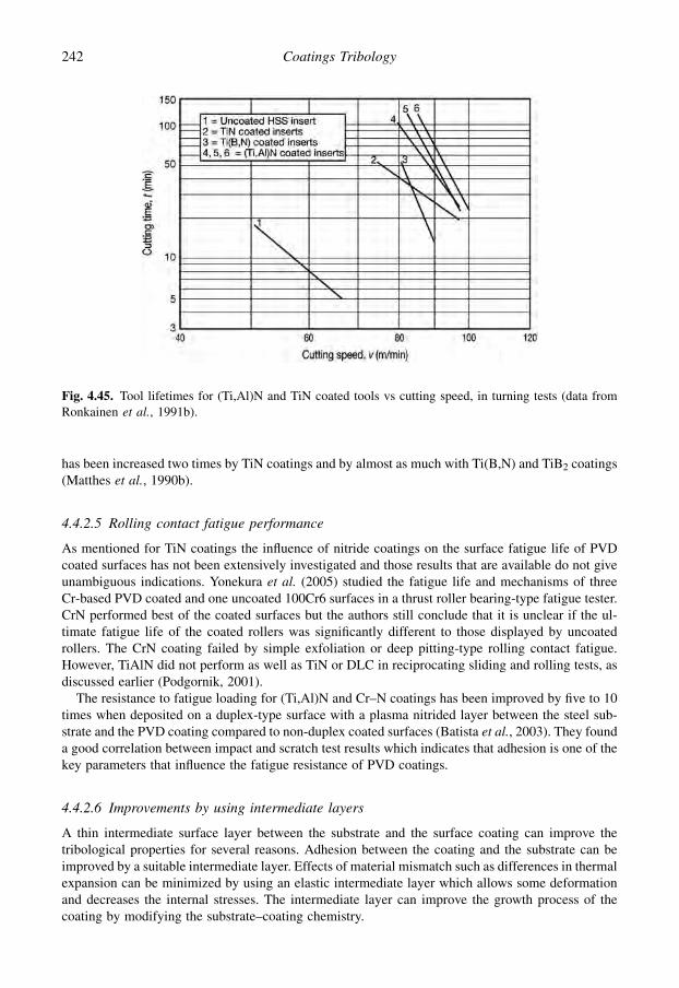
has been increased two times by TiN coatings and by almost as much with Ti(B,N) and TiB2 coatings(Matthes et al., 1990b).
4.4.2.5 Rolling contact fatigue performance
As mentioned for TiN coatings the influence of nitride coatings on the surface fatigue life of PVDcoated surfaces has not been extensively investigated and those results that are available do not giveunambiguous indications. Yonekura et al. (2005) studied the fatigue life and mechanisms of threeCr-based PVD coated and one uncoated 100Cr6 surfaces in a thrust roller bearing-type fatigue tester.CrN performed best of the coated surfaces but the authors still conclude that it is unclear if the ul-timate fatigue life of the coated rollers was significantly different to those displayed by uncoatedrollers. The CrN coating failed by simple exfoliation or deep pitting-type rolling contact fatigue.However, TiAlN did not perform as well as TiN or DLC in reciprocating sliding and rolling tests, asdiscussed earlier (Podgornik, 2001).
The resistance to fatigue loading for (Ti,Al)N and Cr–N coatings has been improved by five to 10times when deposited on a duplex-type surface with a plasma nitrided layer between the steel sub-strate and the PVD coating compared to non-duplex coated surfaces (Batista et al., 2003). They founda good correlation between impact and scratch test results which indicates that adhesion is one of thekey parameters that influence the fatigue resistance of PVD coatings.
4.4.2.6 Improvements by using intermediate layers
A thin intermediate surface layer between the substrate and the surface coating can improve thetribological properties for several reasons. Adhesion between the coating and the substrate can beimproved by a suitable intermediate layer. Effects of material mismatch such as differences in thermalexpansion can be minimized by using an elastic intermediate layer which allows some deformationand decreases the internal stresses. The intermediate layer can improve the growth process of thecoating by modifying the substrate–coating chemistry.
Fig. 4.45. Tool lifetimes for (Ti,Al)N and TiN coated tools vs cutting speed, in turning tests (data fromRonkainen et al., 1991b).
242 Coatings Tribology

The wear properties of the extremely hard cubic boron nitride coating on a tool material like WC–Co alloy or high-speed steel can be improved by introducing a titanium intermediate layer (Murakawaand Watanabe, 1990). Improvements have also been achieved by applying a silicon nitrideintermediate layer between the c-BN and different substrates (Inagawa et al., 1989).
4.4.3 Carbide coatings
Metal carbides are generally hard and have a high melting point and good tribological properties. Thecoefficient of friction for bulk carbides sliding on themselves is low, typically about 0.2 (Mordike,1960). This is about one-third of the coefficient of friction value for steel sliding against steel.
Many different kinds of carbides have been used as thin tribological coatings. They have in generalshown low friction, often in the range of 0.15 to 0.4 and good wear resistance. After titanium nitride,titanium carbide (TiC) is one of the most widely investigated thin ceramic coatings. Good tribologicalproperties can be expected because of its high hardness, about 3.5 GPa HV, which is higher thanthe typical value for titanium nitride of 2 GPa. Other extremely hard carbides are silicon carbide(SiC), Hv z 4 GPa, and boron carbide (B4C), Hv z 5 GPa. Interesting tribological coating materialsare also tungsten carbide (WC), chromium carbide (CrC), vanadium carbide (VC) and tantalumcarbide (TaC).
4.4.3.1 Sliding contact with TiC against steel
There are considerable advantages in using conventional steel as a counterface material. In a widerange of contact conditions the friction is low, in the range of 0.1 to 0.4, and low wear has beenobserved for both PVD and CVD produced TiC coatings sliding against steel (Habig et al., 1980;Hintermann, 1981; Boving et al., 1987; Matthews et al., 1987; Franklin and Beuger, 1992). However,Suri et al. (1979) and Jamal et al. (1980) have reported experimental results, both performed in thesame laboratory using activated reactive evaporation TiC coatings, for the coefficient of friction thatare at a higher level of 0.5 and 0.7. The reason for this discrepancy is not clear but it indicates that lowfriction contact conditions are not necessarily always present with this material combination.
Boving et al. (1987) measured coefficients of friction around 0.3 in dry air and vacuum for a CVDTiC coating sliding against steel, while it decreased to 0.2 when the experiments where carried out in50% humidity. This indicates that an environmental effect is present; a layer of TiO2 is built up on thetop of the coating in humid air and this decreases friction. In lifetime tests Maillat and Hintermann(1985) compared the fretting wear resistance of several soft and hard coatings and found that TiC inthis respect was one of the best wear-protecting coatings. The build-up of a tribolayer that works asa lubricious buffer between work materials and TiC coated tools in cutting contacts has an importantfriction and wear-reducing effect (Hedenqvist and Olsson, 1991; Aizawa et al., 2005).
4.4.3.2 Sliding contact with TiC against other materials
Excellent tribological properties have been reported for two hard coating combinations, TiC–TiC andTiC–TiN, sliding against each other. The coefficient of friction is low, 0.15 to 0.3, and the wear verylow (Jamal et al., 1980; Hintermann, 1981; Matthews et al., 1987; Habig, 1990; Franklin and Beuger,1992). The low friction might be explained by the formation of a low shear layer, for example anoxide, on top of the hard coatings. Low coefficients of friction have also been observed with TiCsliding on other hard materials like aluminium oxide and silicon carbide coatings (Hintermann, 1981)and diamond (Knight et al., 1990). Figure 4.46 shows that TiC and TiN coatings sliding on each otherin different combinations in general give very low friction and wear. It is interesting that the frictionand wear values in several cases are not decreased, as would be expected, but increased whena kerosene oil lubricant is introduced.
243Tribological Properties of Coatings

4.4.3.3 Sliding contact with chromium carbide coatings
According to dry sliding experiments by Habig et al. (1980) the coefficient of friction of a chromiumcarbide coating sliding against steel is about twice as high, 0.3 to 0.5, and the wear about one order ofmagnitude higher than for titanium nitride or titanium carbide in the same sliding conditions. This isprobably attributable to a higher adhesion between the chromium carbide and the steel. Even highercoefficients of friction in the range of 0.4 to 0.6 have been measured by Lindgren and Johnson (1987)for chromium carbide sliding against steel in different helium environments at high temperature.
4.4.3.4 Sliding contact with boron carbide coatings
Boron carbide is an extremely hard coating. Experiments performed at very low sliding speeds by Reyet al. (1988) with a chemically vapour-deposited trigonal boron carbide (B13C2) coating slidingagainst itself, against various ceramics and against steel showed that it has very good friction and wearproperties especially in abrasive conditions. The lowest friction coefficient, 0.15, was obtained forB13C2 sliding against itself and the wear was very low. With B13C2 sliding against aluminium oxide,zirconia, silicon nitride, silicon carbide and steel the coefficient of friction was in the range 0.2 to 0.4but considerably more wear in the form of deep scratches occurred on the ceramic and steel surfacescompared to sliding conditions with B13C2 as a counterface. Only the hardest ceramics (SiC, Al2O3)managed to produce some wear on the B13C2 surface. However, in general the nature of the coun-terface material does not seem to have much effect on the friction coefficient or on the wearphenomena.
Similarly, low friction coefficients, in the range of 0.08 to 0.2, were measured by Dvorak et al.(2002) for annealed boron carbide coatings in reciprocating sliding against a transparent sapphirehemisphere loaded at 6.4 N at a sliding speed of 0.001 m/s. Raman spectroscopy of the formed surfacelayer revealed a mixture of boric acid and carbon initially. As friction increased from a lower initial
Fig. 4.46. The coefficient of friction and the wear of the pin and the disk in dry and oil lubricated slidingcontacts with reactively evaporated TiC coatings sliding against different surface materials at a speed of0.1 m/s and a load of 40 N (data from Jamal et al., 1980).
244 Coatings Tribology

value, the boric acid intensity decreased to zero while the carbon intensity increased. Boron carbideB4C is also well known for its high hardness and wear resistance. If one of the surfaces in a slidingcontact is B4C, it may polish the countersurface and act as a running-in surface. This process has beenstudied and described by Harris and colleagues (Harris et al., 2002; Siniawski et al., 2003; Borodichet al., 2004).
The remarkably good tribological behaviour of boron carbide coatings is probably related to themechanical properties of the material itself and to its structure due to the processing technology. Theabsence of any bonding material, of impurities at grain boundaries, and of porosities can also havea beneficial effect on the behaviour of boron carbide. The value of the coefficient of friction obtainedis in fact lower than the value obtained for the sintered material.
4.4.3.5 Sliding contact with vanadium carbide coatings
In sliding pin-on-disk tests Wang (1997) found that depositing different steel substrates with 6 to14 mm thick VC coatings in dry sliding with loads in the range of 30 to 90 N and a speed of 0.5 m/s theVC coating improved the wear resistance by nine to 30 times compared to uncoated surfaces. Witha VC coating no running-in wear was observed.
4.4.3.6 Abrasive and erosive wear resistance of carbides
In abrasive and erosive wear the hardness of the surface is an important parameter. Thus the hard carbidecoatings can be expected to have good resistance to these wear mechanisms (Borodich et al., 2003; Boseand Wood, 2005). In an abrasive wear test the wear resistance of chemically vapour-deposited TiC andW2C coatings was compared to that of much thicker electroplated and sprayed coatings and anodizedand bath nitrided surfaces (Archer and Yee, 1978). The best wear resistance was measured for a hard12 mm thick TiC coating and a 30 mm thick W2C coating.
In another comparison test performed by Suri et al. (1979) considerably higher abrasive wearresistance was observed for PVD TiC coatings in comparison to boron ion implanted and untreatedstainless steel surfaces. On the other hand, both boron and nitrogen ion implanted, as well asuntreated, surfaces had a better erosive wear resistance compared to the hard TiC coating. Theseobservations indicate a ductile erosive behaviour for untreated and ion implanted materials but brittlebehaviour for the overlay coated substrates.
Both hardness and thickness have been found to influence the erosion resistance of 2 to 11 mm thickchemically vapour-deposited TiC, Al2O3 and B13C2 coatings in erosion experiments performed byOlsson et al. (1989). The hardest coating, B13C2, had a very high erosion resistance and the secondhardest coating, TiC, had a significantly better erosion resistance than Al2O3. For TiC and Al2O3 inparticular the erosion rate increased approximately linearly with increasing coating thickness.
For TiC, Olsson et al. found that erosion predominantly occurs by an intercrystalline fracturemechanism. The erosion proceeded through both the outer and inner TiC zones and into the cementedcarbide substrate without any evidence of interfacial spalling. These observations indicate that theerosion of TiC in principle is by an elastic–plastic mechanism, but that the formation of in-tercrystalline cracks modifies the crack pattern. The authors suggest that in order to obtain higherosion resistance for TiC coatings the porosity, grain size and coating thickness should be kept as lowas possible. The dominant material removal mechanism for the B13C2 coating seemed to be micro-chipping of small, about 10 mm in diameter, fragments due to indentation of sharp corners of theimpinging alumina particles. This was followed by extensive spalling.
4.4.3.7 Rolling contact wear of carbides
Boving and Hintermann (1987) have shown that for thin CVD TiC coatings, with a thickness of 4 mm,on steel substrates the TiC coating follows the substrate deformation in a rolling point contact,
245Tribological Properties of Coatings
provided that the stress applied on the coated substrate remains below the elastic limit of the substrate.One conclusion from this work is that TiC coatings can exhibit excellent adherence to the substrate, aswell as good rolling contact fatigue resistance.
Dill et al. (1984) showed that in addition to CVD TiC coatings, reactively sputtered TiN coatingsalso have an excellent adhesion and spalling resistance in rolling contacts. However, they obtained thebest rolling contact fatigue results for a CVD produced CrC–TiC coating where the substrate was firstlayered with 2 mm CrC and then with 3 mm TiC. This coating showed an excellent resistance to rollingcontact fatigue in rolling point contacts with Hertzian contact pressures up to more than 4 GPa, whichis remarkable.
It is interesting to note, on the contrary, that when Archer and Yee (1978) performed rolling contactfatigue life tests with 30 mm thick W2C coatings on high-speed tool steel the coating flaked ratherrapidly. This might be due to the fact that the higher thickness of the hard coating creates higherstresses in the coating and makes it more brittle and less deformable with the substrate. Also in therolling contact fatigue tests carried out by Remigiusz et al. (2004) there was no clear improvement infatigue life for WC–C coated bearing steel cones rolling against steel balls compared to uncoated.
4.4.4 Oxide coatings
Oxide coatings can be produced by several coating techniques to improve friction and wear properties.One of the industrial applications of such thin hard coatings is the use of aluminium oxide (Al2O3)layers produced by chemical vapour deposition on cemented carbide inserts used as metal cuttingtools. Coatings a few micrometres thick can resist the high forces and temperatures at the tip andimprove the tool lifetime by a factor of 10 (Lux et al., 1986; Larsson, 2000).
4.4.4.1 Aluminium oxide coatings
Most reported tribological studies on alumina coatings are on those deposited by CVD at hightemperature. Typically, these are crystalline of the k or a phase (or a mixture). Alumina films formedby other techniques are usually amorphous. In sliding contacts aluminium oxide coatings normallyhave good wear resistance and medium friction. Typical values for the mechanical properties of CVDAl2O3 coatings are hardness of about 20 GPa, elastic modulus of 250 GPa and a fracture toughness ofabout 2 MPa $ m0.5 (Diao et al., 1994b).
In pin-on-disk experiments Hintermann (1981) measured a coefficient of friction of 0.45 for a CVDAl2O3 coated pin sliding against steel at a speed of 0.01 m/s and a load of 20 N. With a titaniumcarbide coated disk as counterface the coefficient of friction was only 0.19 and the wear was very low.The disk wear rate was 0.5 $ 10�6 mm3/Nm and the pin wear rate as low as 0.005 $ 10�6 mm3/Nm.Roth et al. (1987) have studied the structure, internal stresses and mechanical properties of sputteredAl2O3 coatings and found that the adhesion increases with increased coating thickness and reachesa high level for coatings thicker than 3 mm as shown in Fig. 4.47. In ring-on-plate experiments theymeasured good wear resistance for 4 mm thick Al2O3 coatings sliding against steel.
For CVD Al2O3 coatings with a TiC interlayer on cemented carbide substrates exposed tobombarding erosive particles, Olsson et al. (1989) found that an increase in coating thickness de-creases the wear resistance. They found that chipping by transcrystalline fracture is the dominanterosion mechanism and subsurface cracks were observed in cross-sections. For thicker Al2O3 coat-ings, interfacial spalling at the Al2O3/TiC interface occurred at an early stage.
The basic mechanical aspects of very thin oxidized surfaces on aluminium and chromium slidingagainst a similar countersurface in lubricated pin-on-disk tests with a load range of 0.02 to 2 N and atspeeds of 0.006 to 0.035 m/s were investigated by Komvopoulos (1991a, b). He found that under thesesliding conditions the coating deforms elastically and the friction is mainly due to shear of theboundary lubricant film. The experimental results verified that the elastic and plastic deformation at
246 Coatings Tribology

the sliding interface strongly depends on coating thickness, surface roughness, microstructure of thecoating and the mechanical properties of the coating in relation to those of the substrate. Surfaceprofilometry and optical and scanning electron microscopy showed that when the coating was notremoved the surface damage was virtually zero.
4.4.4.2 Titanium, cadmium and chromium oxide coatings
Other oxide coatings, such as the oxides of titanium, cadmium and chromium, have not been ex-tensively investigated for tribological purposes.
For a titanium oxide PVD coated pin sliding on a steel disk at a speed of 0.2 m/s and a load of 5 NMatthews et al. (1987) measured a fairly low coefficient of friction of only 0.3, and a wear rate of0.8 $ 10�6 mm3/Nm, of the same order of magnitude as that for TiN or TiC coatings in the sameconditions. With copper as the counterface the coefficient of friction increased to above 0.6.
Sputtered cadmium oxide disks sliding against a steel ball in a pin-on-disk device with a speed of0.26 m/s and a load of 10 N showed a very low coefficient of friction in the range of 0.17 to 0.23, inexperiments performed by Fusaro (1987b). The friction was of the same level as for graphite surfacesin the same conditions. However, even though the wear rate in the contact was reasonably low theendurance life was short – only about 15 kilocycles. The endurance life was defined as the sliding timein kilocycles to reach a friction coefficient of 0.25.
Chromium oxide layers deposited by CVD on layers of silicon oxide and aluminium oxide (Cr2O3/SiO2/Al2O3) on steel forming a 30 mm thick uniform and continuous coating showed very goodscratch adhesion properties, almost at the same level as TiN, and good abrasive wear resistance inexperiments performed by Bhansali and Kattamis (1990). In the scratch test the coefficient of frictiongradually increased with increasing normal load to about 0.3, which is approximately equal to thevalue measured for TiN. Three different wear modes were identified for 400 mm thick plasma sprayedCr2O3 coatings on stainless steel substrates when a spherical diamond tip was repeatedly sliding overthe surface at a load of 0.07 to 1.5 N and a speed of 0.0004 m/s with increasing load: (1) crack andpowder formation correlating to low wear rate; (2) flake formation correlating to high wear rate; and(3) ploughing and powder formation correlating again to a low wear rate (Kitsunai et al., 1991).
Fig. 4.47. Variation of the adhesion related critical load LC for sputtered Al2O3 coatings vs coatingthickness (data from Roth et al., 1987).
247Tribological Properties of Coatings
4.4.5 Boride coatings
Boride coatings are generally very hard and can be used mainly in tribological applications wheregood abrasive wear resistance is needed. The coefficient of friction in contacts with boride coatings isgenerally fairly high. Tribologically interesting boride coatings are titanium diboride and iron boride.Iron boride coatings may be useful as brake materials because of their peculiar tribological property ofgiving very low wear and high friction at the same time.
4.4.5.1 Titanium diboride coatings
Titanium diboride (TiB2) is a ceramic material with a hexagonal structure which has various attractiveproperties, such as high hardness, excellent corrosion resistance, good thermal oxidation resistanceand good wear resistance. Very low wear has been obtained in sliding contacts with brittle and hardtitanium diboride coatings. However, the adhesion to the substrate has often been a problem and thefriction is high when sliding against steel, often in the range of 0.4 to 0.9 (Kullmer et al., 2003;Podgornik et al., 2006b). For thick PVD TiB2 coatings Berger (2002) measured the following me-chanical properties: hardness 50 GPa, elastic modulus 600 GPa and fracture toughness 4 MPa $ m0.5.
In dry sliding contacts at a variety of temperatures up to 540�C a very low incremental wear ratewas measured for 30 to 40 mm thick CVD titanium diboride coatings in sliding contact againsta chromia–silica–alumina coating in experiments performed by Levy and Jee (1988). However, thecoefficient of friction was fairly high, about 0.6 to 0.8, at room temperature and increased withtemperature to slightly over 1 at 540�C. It was a little lower than for the other plasma sprayed thickcoatings tested, Cr3C2–Mo, WC–Mo, TiC–Mo and Al2O3–TiO2. The high coefficient of friction madethe TiB2 coating, as well as the other coatings tested, unsuitable for sliding component applicationslike bearings or piston ring vs cylinder wall contacts. A compound layer was formed on both the TiB2
and the counterface and probably played a major role in the tribological behaviour of the contact.In pin-on-disk tests with a TiB2 coated surface sliding against itself at a speed of 0.1 m/s and a load
of 2.5 N Habig (1990) found a high and constant wear rate both in air and in vacuum but a higherinitial wear in vacuum. The wear volume was about six times that of TiN against TiN in similarcontact conditions and the coefficient of friction was in the range of 0.4 to 0.6 in air and 0.75 invacuum. The relative humidity of the air environment was 50%.
In scratch adhesion tests, lower critical load values have been obtained for TiB2 coatings comparedto TiN coatings (Bhansali and Kattamis, 1990; Matthes et al., 1990b; Podgornik et al., 2006b) whichsuggests that while the adhesion of the coating is reasonable, it is not of the level of TiN. The stressesand strains in the scratch test contact between the diamond stylus and a TiB2 coated high-speed steelsurface were FE modelled and simulated by Panich and Sun (2006). They also found that sputtercleaning of the substrate helps to improve the TiB2 coating hardness and adhesion strength.
In metal forming wear tests with PVD deposited TiB2 coatings on grey cast iron Matthes et al.(1990b) measured good lifetime results at the same level as TiN coatings. The wear performance ofthe TiB2 coated tools was limited by cracking under high loads on the drawing edge. In abrasive weartests Bhansali and Kattamis (1990) found that the wear resistance of TiB2 coatings was not as good asthat of TiN coatings.
4.4.5.2 Iron boride coatings
Extremely good sliding wear resistance has been obtained for CVD iron boride coatings on steelsliding against itself. Habig et al. (1980) have compared the tribological properties of CVD coatedFeB, TiN, TiC and CrC sliding against themselves. Iron boride showed the very lowest wear rate; itwas one order of magnitude less than for TiN and TiC and two orders of magnitude less than for CrC.However, the coefficient of friction was not so very low. For FeB it was 0.38 to 0.63, which is
248 Coatings Tribology

considerably higher than the very low values measured in the same conditions for TiN, 0.19, and TiC,0.13. The coefficient of friction is also high, 0.76, when a CVD FeB coated steel specimen is slid withsteel as the counterface, according to Hintermann (1981). The coefficient of friction was three timesgreater than for TiC and half as high as for TiN sliding against steel.
4.5 Carbon and Carbon-based Coatings
4.5.1 Diamond as a coating material
Diamond and diamond-like carbon-based coatings have attracted a rapidly increasing number ofresearchers since the middle of the 1980s and these layers are today the most intensively researchedtribological coatings. Work on the deposition of diamond films was already under way in the 1950sbut the research boom was triggered in the early 1980s when deposition rates reached the order of1 mm/h. The commercial interest in diamond and diamond-like coatings is considerable, not onlybecause of their great potential in tribological applications but also because of their potential as newand more efficient semiconductor and optical thin film materials. Diamond-like carbon coatings areextensively used in the computer industry. Practically all magnetic hard disks produced are coveredwith a multilayer film including a wear protective carbon-based coating. Other successful tribologicalapplications are diamond-like carbon coatings on tools for cutting of non-ferrous materials and onvarious sliding components.
Diamond is attractive as a tribological material due to its unique material properties: highmechanical strength, high hardness, chemical inertness, excellent thermal conductivity, extremelylow thermal expansion, low friction and good wear resistance.
Polycrystalline diamond and amorphous diamond-like coatings are two specific forms of carbonsurface layers. Carbon occurs in them as diamond or graphite allotrope or as amorphous carbon.Diamond is a metastable phase of carbon at room temperature and pressure. Diamond has a cubiccrystal structure with a fourfold sp3 covalent bond structure (Fig. 4.48a). Graphite has a hexagonallattice structure with sp2-bonded two-dimensional planes interconnected by weak forces (Fig. 4.48b).A third synthetically produced structure of pure carbon are the fullerenes that may have a ball or a tubeform (Fig. 4.48c). Amorphous carbon is a transitional form of carbon which has no long range orderand the local structure varies depending on the growth procedure (Fig. 4.48d).
The stable phase of carbon at 300 K and 105 Pa is graphite. The diamond phase is stable at 300 K forpressures greater than 1.6 $ 109 Pa, but the conversion of graphite to a diamond structure demandspressures and temperatures of much higher magnitude. The structure and properties of diamondcoatings have been described by Derjaguin and Fedoseev (1975), Bachmann and Messier (1989),
Fig. 4.48. Carbon structures in (a) diamond, (b) graphite, (c) fullerene ball and (d) amorphous diamond-likecarbon.
249Tribological Properties of Coatings

Spear (1989), Angus (1992), Gardos (1994), Erdemir and Donnet (2001) and Miyoshi (2001).Detailed tribological studies on diamond and diamond-like carbon coatings carried out in numerousresearch and industrial laboratories in the 1990s has confirmed that they are inherently self-lubricatingand exhibit an excellent resistance to adhesive, abrasive and erosive wear. In addition, they areresistant to corrosion and oxidation.
It is possible to deposit diamond and diamond-like coatings at low pressure by using a large varietyof deposition techniques mainly based on chemical and physical vapour deposition. The mostcommon are hot filament CVD and microwave plasma CVD for depositing diamond coatings, andradio frequency, laser or arc-assisted PVD or CVD for diamond-like coatings. Details on the differentdeposition techniques are found in Spitsyn et al. (1988), Lux and Haubner (1989), Rossi (1992) andAndersson (2004). Perhaps the most surprising deposition technique for diamond coatings is thecombustion flame technique. Based on the combustion of an acetylene oxygen mixture from an oxy-acetylene torch at atmospheric pressure this simple procedure results in nucleation of diamondcrystals at high deposition rates of 1 mm/min (Ravi et al., 1990; Murakawa et al., 1990; Alahelisten,1994; Hollman, 1997a).
In a tribological sense diamond coatings behave very much like natural diamond but also amor-phous diamond-like coatings have very similar properties. Only in certain respects, like the influenceof humidity on friction, is the behaviour of diamond-like coatings more like that of graphite (Miyoshi,1990; Erdemir et al., 1991c; Feng and Field, 1991; Miyoshi et al., 1992; Donnet and Erdemir, 2008).There are several different techniques for identification and characterization of diamond anddiamond-like surfaces (Tsai and Bogy, 1987; Williams and Glass, 1989; Robertson, 1992a, b;Miyoshi, 2001; Ferrari, 2008). Raman spectroscopy is particularly suitable for identification of di-amond structures and is commonly used (Knight and White, 1989; Huong, 1991; Blanpain et al.,1992; Ferrari, 2008).
4.5.1.1 Bulk diamond
Diamond has many unique properties. The one which makes it particularly interesting from a tri-bological point of view is that it is the hardest known material. In addition, it is chemically inert andnon-toxic, can withstand extreme temperatures, conducts heat faster than any other solid substance, isan excellent electrical insulator and has low thermal expansion. The topography of a diamond surfacemay vary from extremely smooth to rough with pyramidal asperities, depending on its crystallineorientation and how it has been polished. Typical values for the mechanical properties of diamond are:hardness 60 to 100 GPa Hv, elastic modulus 910 to 1250 GPa and Poisson’s ratio 0.1 to 0.29 (Miyoshi,2001).
4.5.1.2 Diamond sliding against diamond
The very favourable tribological properties of diamond were recognized and studied by Bowden andTabor (1950). They reported coefficients of friction as low as 0.05 and extremely small surfacedamage. They suggested that friction arises from the low adhesion of the two diamond surfaces whichare each covered with a contaminant layer across which van der Waals forces act (Bowden and Tabor,1964). However, this theory cannot alone explain the observed frictional anisotropy (Brookes andBrookes, 1991; Gardos, 1994) and the fact that friction is reported to be unaffected by the addition ofa lubricating oil on the surfaces (Samuels and Wilks, 1988; Feng and Field, 1991; Grillo and Field,2003).
The tetrahedral bonding structure of a diamond results in a situation at the surface where there willbe one vacant electron coming out from the surface that has no carbon atom to attach to, as shown inFig. 4.49a. This is called a dangling bond orbital (Tabor, 1979). If one hydrogen atom with its ownelectron is put on each such carbon atom, it will bond with the dangling bond orbital to form a
250 Coatings Tribology
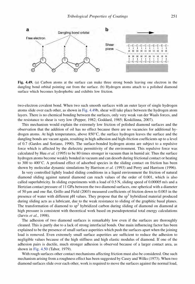
two-electron covalent bond. When two such smooth surfaces with an outer layer of single hydrogenatoms slide over each other, as shown in Fig. 4.49b, shear will take place between the hydrogen atomlayers. There is no chemical bonding between the surfaces, only very weak van der Waals forces, andthe resistance to shear is very low (Pepper, 1982; Goddard, 1985; Koskilinna, 2007).
This mechanism would explain the extremely low friction of polished diamond surfaces and theobservation that the addition of oil has no effect because there are no vacancies for additional hy-drogen atoms. At high temperatures, above 850�C, the surface hydrogen leaves the surface and thedangling bonds are vacant again, resulting in high adhesion and high-friction coefficients up to a levelof 0.7 (Gardos and Soriano, 1990). The surface-bonded hydrogen atoms are subject to a repulsiveforce which is affected by the dielectric permittivity of the environment. This repulsive force wascalculated by Huu et al. (1995) to be 80 times stronger in vacuum than in humid air. Thus the surfacehydrogen atoms become weakly bonded in vacuum and can desorb during frictional contact or heatingto 300 to 400�C. A profound effect of adsorbed species in the sliding contact on friction has beenshown by molecular dynamic simulations by Harrison et al. (1993) and Perry and Harrison (1996).
In very controlled lightly loaded sliding conditions in a liquid environment the friction of naturaldiamond sliding against natural diamond can reach values of the order of 0.001, which is alsocalled superlubricity. In sliding experiments with a load of 0.5 N, sliding speed of 0.00005 m/s and aHertzian contact pressure of 11 GPa between the two diamond surfaces, one spherical with a diameterof 50 mm and one flat, Grillo and Field (2003) measured coefficients of friction down to 0.003 in thepresence of water with different pH values. They propose that the sp2 hybridized material producedduring sliding acts as a lubricant, due to the weak resistance to sliding of the graphitic basal planes.The transformation of diamond to sp2 hybridized carbon during sliding of diamond on diamond athigh pressure is consistent with theoretical work based on pseudopotential total energy calculations(Jarvis et al., 1998).
The adhesion of two diamond surfaces is remarkably low even if the surfaces are thoroughlycleaned. This is partly due to a lack of strong interfacial bonds. One main influencing factor has beenexplained to be the presence of small surface asperities which push the surfaces apart when the joiningload is removed. Even extremely small surface asperities are sufficient to reduce the adhesion tonegligible values because of the high stiffness and high elastic modulus of diamond. If one of theadhesion pairs is ductile, much stronger adhesion is observed because of a larger contact area, asshown in Fig. 4.50 (Tabor, 1979).
With rough surfaces other contact mechanisms affecting friction must also be considered. One suchmechanism arising from a roughness effect has been suggested by Casey and Wilks (1973). When twodiamond surfaces slide over each other, work is required to move the surfaces against the normal load,
Fig. 4.49. (a) Carbon atoms at the surface can make three strong bonds leaving one electron in thedangling bond orbital pointing out from the surface. (b) Hydrogen atoms attach to a polished diamondsurface which becomes hydrophobic and exhibits low friction.
251Tribological Properties of Coatings

as they are forced apart when asperities ride over each other. As the asperities are rough and jagged,this transference of contact may take place abruptly and irreversibly, with some of the work ofseparation degenerating into heat. This friction mechanism is frequently called the ratchet mecha-nism. The main problem with this theory is that the energy used in ascending the asperities to createthe measured friction values would be larger than is reasonably expectable.
The effects of surface roughness, fracture, the ratchet mechanism and elastic losses have beenanalysed by Hayward and Field (1987), Samuels and Wilks (1988) and Hayward (1991). There areindications that microscopic plastic deformation occurs at diamond contacts but it is not clear how thiseffect should be taken into account in the friction models (Feng and Field, 1992). It has been spec-ulated that there may be some graphitization at the contact tips.
When a rough diamond surface is sliding over another, small asperity fragments are chipped awayand the resulting surface probably consists of a series of asperities whose faces are easy-cleavageplanes. This is in agreement with the observation that the wear rate does not increase with temper-ature, and that the wear rate is very dependent on the direction of sliding (Hayward, 1991). The wearrate of diamond sliding on diamond is extremely low but after a longer period of sliding smallquantities of debris are collected at the sides or the end of the wear track. The debris, with observedsizes of up to 20 mm in diameter, has been analysed by various methods which indicate that the debrismaterial consists mainly of hydrocarbons, with a little graphite but no diamond (Hayward, 1991; Fengand Field, 1992). It is also possible that a portion of the carbon in the debris does not originate fromthe diamond, but from the polymerization of adsorbed hydrocarbons.
It is possible that the debris formed has a considerable role in the mechanism producing low frictionwith sliding diamond surfaces and that it is a consequence of some slippery debris layer or microfilm onthe top of the surface. The erosion resistance of diamond has been studied by Hayward and Field (1990)and they found that it is very high, even when compared with the erosion resistance of ceramics.
Experimental tribological studies of diamond sliding on diamond at fairly moderate speeds result inthe following conclusions:
1. The coefficient of friction is in the range 0.05 to 0.15 over a wide range of experimental conditions.It rarely exceeds 0.2 in air and room temperature.
2. The friction depends on crystal face and orientation. A variation in the coefficient of friction from0.05 to 0.10 through a 360� rotation has been reported by Casey and Wilks (1973).
3. At low loads the influence of sliding speed and load is very small. At very low loads and slidingspeeds in a water environment a coefficient of friction as low as 0.003 has been measured (Grilloand Field, 2003). At high loads appreciable surface damage and higher friction has been observed.
4. There is almost no effect on friction when a lubricant such as a mineral oil is introduced but thereare conflicting results reported for the influence of moisture and water on friction (Feng and Field,1991; Miyoshi et al., 1992).
Fig. 4.50. The contact geometry for (a) a rough diamond surface on another diamond surface and(b) a rough diamond surface on steel.
252 Coatings Tribology

5. The influence of surface roughness is crucial.6. Diamond contacts are affected by extreme environmental conditions. At temperatures above 850�C
the coefficient of friction increases to a level of 0.7 and in ultra-high vacuum it is approximately 1.0(Gardos and Soriano, 1990).
It is important to note that many of these observations were a result of testing with single-crystaldiamond samples. Polycrystalline diamond films, however, often have a variety of crystallographicorientations present in the contact interface and the surface film is microscopically rough, which canbe expected to change the above observations.
4.5.1.3 Diamond sliding against metals
When a diamond surface slides against a metal the surface topography of the diamond has a signifi-cant influence on friction and wear. This indicates that ploughing or abrasive effects caused by di-amond surface asperities or loose wear particles have an important role in the contact mechanism inaddition to adhesive effects.
A diamond surface does not undergo significant wear in sliding contact with metals except forsmall polished areas and fine scratches. In contacts with smooth diamond surfaces the metal wear isgenerally low and the coefficient of friction can be less than 0.1.
Severe wear occurs if the surface roughness of the diamond exceeds about Ra¼ 0.3 mm and highvalues of the coefficient of friction up to 0.7 occur. Mehan and Hayden (1981–82) claim in a detailedexperimental study of diamond and metal contacts that oxidational wear with the production of hardFe2O3 abrasive particles can have a dominating effect on the wear process. When they inhibited theformation of surface oxides by performing the experiments in a nitrogen atmosphere very low wearand friction was observed. The introduction of lubricating oil into the contact decreased the frictionboth for smooth and rough diamond surfaces.
The study by Mehan and Hayden (1981–82) shows that diamond has better tribological propertiesthan other hard materials such as alumina, cemented tungsten carbide, silicon nitride and hard metals.Yust et al. (1988) have reported an extremely low coefficient of friction of only 0.02, with diamondsliding on ion-implanted titanium diboride (TiB2).
4.5.2 Diamond coatings
Chemical vapour deposition offers an elegant way to produce thin diamond layers on surfaces. Itincludes the decomposition of hydrocarbon, such as methane, with some form of activation technique,in the following way:
CH4 / Activation / C ðdiamondÞ þ 2 H2
The activation techniques may be high temperature and/or plasma, both of which require energyinput. The carbon species in the hydrocarbon molecule must be activated, since at low pressuregraphite is thermodynamically stable. Without activation only graphic material would be formed.
Depending on the predominant electron state of carbon atoms, the degree of crystallinity and otherfactors, three kinds of carbon films are identified: diamond, diamond-like and graphite-like carbonfilms. Diamond coatings have a polycrystalline structure which predominantly consists of the crys-talline tetrahedral sp3 bondings and only a small number of sp2 and sp bonds at the boundaries ofdiamond crystallites. As the amount of sp2 and sp bonds increases, the structure changes to becomemore amorphous (Spitsyn et al., 1988; Hirvonen, 1991; Gardos, 1994; Erdemir, 2002). Crystallinediamond coatings have an extreme hardness of about 100 GPa and a Young’s modulus over 1000 GPa.
A detailed review of the structures and mechanical properties of diamond and diamond coatings hasbeen written by Miyoshi (2001). Diamond films can be grown on some ceramic and metallic
253Tribological Properties of Coatings

substrates such as Si and W and their carbides by CVD methods. Typical substrate temperatures fordiamond film deposition are 600 to 950�C. For deposition of diamond below 600�C the growth rateand diamond quality is substantially reduced. Because of the high thermal conductivity and electricalinsulation, diamond coatings are used as a heat sink in X-ray windows, circuit packing and high-power electronic devices (Erdemir and Donnet, 2005). Carbon coatings, including basic knowledge,film classification and their properties, are described in the standard VDI-Richtlinien (2005).
4.5.2.1 Stresses in the coating
The tribological behaviour of a diamond coating is influenced considerably by the residual stresses inthe coating. They consist of two main components, the thermal stresses and the intrinsic growthstresses. The thermal stresses can be calculated from the differences in thermal expansion between thesubstrate and the coating. The thermal expansion coefficient of diamond is in the range of 1.5 to4.8 $ 10�6 K�1, which is low compared to many ceramics and very low compared to most metals.Thus compressive thermal stresses will be induced when, for example, aluminium oxide, siliconcarbide or zirconium oxide are used as substrates and the stresses will increase in magnitude as thesubstrate temperature increases during deposition. The expansion coefficient of WC is of the samelevel as diamond, which makes it a suitable substrate material because the diamond film can be de-posited in a virtually stress-free condition (Anthony et al., 1991; Lindbauer et al., 1992; Alahelisten,1994; Hollman, 1997).
For most metals and metal alloys used as substrates the thermal expansion coefficient is high. Thiscan result in coating spallation because of the large residual compressive stresses if the depositiontemperature is high. Conversely, it has been observed that the intrinsic stresses for many diamondfilms are tensile, which will counteract the thermal stresses (Guo and Alam, 1991; Kamiya et al.,1999). The tensile stresses measured by Kamiya et al. (1999) for diamond coatings on Si substratedecreased slowly from 0.2 GPa at the top surface 4 mm from the coating/substrate interface to 0.1 GPaat 0.02 mm from the interface where they drastically changed to highly compressive stresses of morethan �0.6 GPa even closer to the interface. The origin of the tensile intrinsic stresses is oftenexplained by the attractive interatomic forces acting across grain boundaries or micropore gaps. Thiswill induce an elastic strain in the anchored grains and is referred to as grain boundary relaxation.
Based on strain measurements by Raman spectroscopy and FEM calculations Gunnars andAlahelisten (1996) estimated the stresses in diamond coatings on flat geometries and over substrateedges. Far from the edge they found compressive stresses of �2.3 GPa in the coating and low tensilestresses of 0.1 GPa in the cemented carbide substrate. The tensile stresses in a 5 mm thick diamondcoating deposited over a substrate edge with 5 mm radius had tensile normal stresses of 0.80 GPa,shear stresses of 0.46 GPa and tangential compressive stresses of �0.56 GPa. With a larger edgeradius the normal tensile and shear stresses decreased while the tangential compressive stressesincreased to values up to 2 GPa.
4.5.2.2 Environmental effects
At high temperatures, around 600�C, natural diamond crystals begin to oxidize. The temperature atwhich the oxidation begins, as well as the oxidation rate, depends on factors such as the morphologyof the film and the nature and the amount of defects and impurities in the carbon. Usually, diamondcoatings have a significant amount of crystal defects such as twins and dislocations. Microwave andhot filament CVD diamond coatings often contain hydrogen and other impurities affecting the oxi-dation process. According to measurements by Tankala et al. (1990) oxidation of hot filament CVDdiamond films in air is noticeable at about 250�C and it becomes pronounced at 800�C. The oxidationof microwave CVD diamond films starts at a lower temperature. A hot filament CVD film wassomewhat more oxidation resistant than a microwave CVD film. The oxidation behaviour of diamond
254 Coatings Tribology

films has been observed to be kinetically similar to that of natural diamond. One conclusion is thusthat diamond films are not suitable for extended exposure to an air atmosphere at temperatures above600�C. However, in an inert environment they are stable at much higher temperatures and remainoptically transmissive (Johnson et al., 1990).
The chemistry of the test environment may play a significant role in the friction and wear per-formance of diamond coatings. The very low friction and wear performance with diamond films areachieved only in air and with relatively dry inert gases and at low ambient temperatures. In vacuumand at high temperatures the friction and wear are higher. The difference in film structure due to thedifferent deposition techniques results in different environmental influences on the tribologicalbehaviour.
In tribological tests carried out in humid air, dry nitrogen, water and ultra-high vacuum, Miyoshiet al. (1992) and Miyoshi (1998) found that, regardless of the environment, nitrogen ion-implantedCVD diamond films had low steady-state coefficients of friction, less than 0.1, and low wear, less than10�6 m3/Nm when sliding against a CVD diamond pin at a 0.49 N load, 2 GPa Hertzian contactpressure and 0.031 to 0.107 m/s speed. These films can be used as wear-resistant, self-lubricatingcoatings regardless of the environment. On the other hand, as-deposited, fine grain CVD diamond films,polished coarse grain CVD diamond films and polished and then fluorinated, coarse grain CVD di-amond films performed similarly tribologically well in humid air, dry nitrogen and water but had a highcoefficient of friction and a high wear in ultra-high vacuum. Also interesting was that the polished,coarse grain CVD diamond film had an extremely low wear rate, less than 0.0001 $ 10�6 m3/Nm, inwater. This correlates with the experiences reported by Erdemir and Donnet (2005) from tests carriedout in water and oil environments. The friction and wear performance was reported to be exceptionalwith smooth diamond films under oil lubricated sliding. After some initial running-in wear there wasessentially no wear at all.
The variation of surface conditions and friction with the environment and the material in slidingwith very smooth surfaces of diamond against diamond coatings, where the ploughing component canbe neglected, has been illustrated by Miyoshi (1998). With adsorbed contaminants, such as water,carbon oxides or hydrocarbons, the hard diamond film provided a small contact area A (Fig. 4.51a),minimized penetration of the diamond pin and either reduced the shear strength S or maintained thelow surface energy g of the contact area. When the contaminant surface layers were removed byrepeatedly sliding the pin in the same track in ultra-high vacuum the result was stronger interfacialadhesion between the diamond pin and the diamond film and accordingly an increase in the coefficientof friction, as shown in Fig. 4.51b. Removing the contaminant layer from the contact area enhancedadhesion and increased either the shear strength or the surface energy of the contact area.
Fig. 4.51. Contact mechanisms influencing friction in (a) humid air or dry nitrogen and (b) ultra-highvacuum, when diamond is sliding on diamond coatings (after Miyoshi, 1998).
255Tribological Properties of Coatings

4.5.2.3 Surface topography
As most diamond films are both rough, because of their facetted structure, and very hard, it is clearthat surface roughness and topography have a crucial effect on the tribological behaviour in slidingcontacts. This has been experimentally confirmed for diamond coatings in contact with single-crystaldiamond, ceramics and steel. The surface topography of a thin diamond film produced by CVDmethods can vary very much. Typical topographies are pyramidal, microcrystal and plate-like (Blauet al., 1990) as shown in Fig 4.52a, b and c.
Rougher surfaces and pyramidal topographies produce higher friction and more wear because ofabrasive cutting and ploughing effects. On smoother microcrystalline surfaces, on the other hand,effects of material transfer and wear debris in the contact will be more pronounced. Smooth plate-likefilms are tribologically favourable because of fewer abrasive effects. Hard wear particles can beembedded in the spaces between the plates and thus their abrasive actions are reduced (Blau et al.,1990; Gardos, 1998). In contacts between diamond coatings and softer materials, rougher surfaceswill cause more ploughing and cutting effects.
Another mechanism to consider is the running-in wear. In the initial stages of contact there will bequite considerable numbers of asperity collisions because of the roughness of the diamond surface,producing wear debris. After a running-in period the surfaces become smoother and the possibletransfer layers are stabilized, generally resulting in lower wear and friction. The development of thedeposition techniques opens new possibilities to control the surface topography of diamond films.Both extremely smooth diamond surfaces as well as textured surfaces with, e.g., well-controlledprotruding pyramidal abrasive tips have been designed and manufactured for special purposes(Hollman, 1997; Gahlin et al., 1999; Pettersson and Jacobson, 2006).
4.5.2.4 Surface graphitization
One proposed explanation for the extremely good tribological properties of diamond films is theformation of a thin graphite film in the actual contact areas (Jahanmir et al., 1989; Holmberg andMatthews, 1994; Gardos, 1994; Grillo and Field, 2003; Dienwiebel and Frenken, 2007; Miura andSasaki, 2007), as indicated in Fig. 4.52. As diamond is a thermodynamically unstable phase of carbon,at elevated temperatures of 600 to 1500�C, depending on the environmental conditions, it cantransform to graphite. These high temperatures may occur as very short flash temperatures in theasperity collisions. On the other hand, there have been extensive surface analyses carried out bydifferent techniques on worn diamond coated surfaces, but very little clear evidence of a graphite layeron top of the coating has been found. It seems likely that there must be some low shear strengthmicrolayer on the top of the diamond coating to explain the extremely low frictional behaviour but itmay also be some hydrocarbon polymer-like slippery film as suggested by Gardos (1994).
The explanation that the extremely low friction and wear properties of diamond coatings are causedby the transformation of diamond to graphitic carbon and this sp2 hybridized material producedduring sliding acts as a lubricant, due to its weak resistance to sliding of the graphitic basal planes, issupported by Grillo and Field (2003). They carried out a theoretical analysis based on pseudopotentialtotal energy calculations and proposed a model where the dependence on crystal direction and ori-entation, in terms of strains induced at the interface during sliding, is included.
4.5.2.5 Abrasive wear resistance
It is well known that harder materials generally have better abrasive wear resistance so it is no surprisethat coatings of diamond exhibit excellent resistance to abrasive wear (Alahelisten, 1994; Hollman,1997; Andersson, 2004; Bose and Wood, 2005). CVD diamond coatings have been found to havebetter abrasive wear resistance than diamond-like amorphous carbon films (a-C:H) and metalcontaining carbon films (metal-C:H) by Klages (1990).
256 Coatings Tribology

Fig. 4.52. The contact mechanisms for three typical diamond coating topographies: (a) pyramidal,(b) microcrystal and (c) plate-like, when sliding on themselves.
257Tribological Properties of Coatings

When a rough diamond coated surface is sliding against another hard surface, smoothing can takeplace. Gunnars and Alahelisten (1996) observed this process with CVD diamond coating on cementedcarbide substrates sliding against SiC abrasive paper. The wear process started by fragmentation ofprotruding diamond asperities. This proceeded until the surface was relatively flat and thereafter thewear rate diminished to a very low level. By using diamond grains as abrasives the same processoccurred, although the final coating surface was smoother.
Gunnars and Alahelisten propose the following model for the wear process. The stress state in thediamond coating is assumed to be dominated by high biaxial compressive stress. In the beginning ofthe wear process the protruding grains will take up the externally applied stresses, shown as region I inFig. 4.53. The result is that high local stress concentrations and fragmentation occur. The residualstresses are low in the protruding grains since the geometry permits relaxation. A crack nucleated ina protruding grain will propagate preferentially along easy cleavage planes, which are (111) fordiamond. However, a crack that propagates deeper into the coating will encounter higher and highercompressive residual stresses which will deflect the crack into a path, irrespective of cleavage planes,region II in Fig. 4.53. The large residual stresses will prevent cracks initiated at the surface frompropagating towards the interface and thus promote crack paths parallel to the surface. The result isa smooth surface free from asperities, region III in Fig. 4.53.
4.5.2.6 Sliding against single-crystal diamond
The coefficient of friction for diamond sliding on diamond coatings was measured to be in the range of0.03 to 0.5 by Hayward et al. (1992). They found a crucial effect of surface roughness on friction,which decreases as the coating and slider are smoothed by abrasive wear.
In experiments with 1 mm thick CVD diamond films coated on single-crystal silicon substrates andsliding against diamond, the initial coefficients of friction, 0.1 to 0.5, were generally higher than thosemeasured when natural diamond slides on natural diamond, 0.05 to 0.15 (Hayward and Singer, 1990).The initial wear produced debris that caused smooth patches on the coating and resulted in smoothersurfaces. The coefficient of friction decreased at the same time to values as low as 0.05 for thesmoothest surface after about 100 cycles, as shown in Fig. 4.54a. The diamond coatings were suf-ficiently hard to wear the single-crystal diamond sliders.
The low friction coefficients achieved after smoothing of the coatings are similar to those ofpolished single-crystal diamond. When the surfaces were first polished there was no region of initialhigh wear and the coefficient of friction was low from the beginning, as shown in Fig. 4.54b. Theinfluence of surface roughness on the coefficient of friction is well illustrated by Fig. 4.55 whereexperimental data from friction measurements with six different coatings are shown.
The adhesion component of friction in a sliding diamond on diamond coating contact was studiedby Feng and Field (1991). They added water to the contact during the experiment and found that thecoefficient of friction decreased from a level of 0.05 to less than 0.02. This shows that friction has, inaddition to the ploughing component demonstrated by the roughness effect, an adhesion componentalso. This changes when water between the surfaces reduces the area for adhesive bonding. Nohydrodynamic effect would be expected because of the very low sliding speed of 0.0002 m/s. These
Fig. 4.53. Model for the wear process of brittle diamond coatings subjected to high compressive biaxialstresses resulting in surface smoothing (after Gunnars and Alahelisten, 1996).
258 Coatings Tribology

results correlate well with the friction measurements of Miyoshi (1998) carried out in air, nitrogen andwater, discussed earlier.
4.5.2.7 Sliding against diamond coating
When two smooth diamond coated surfaces slide against each other the friction coefficient is normallyvery low, in the range 0.05 to 0.15, and the wear rates are equally low, about 0.1 $ 10�6 mm3/Nm invacuum and a little higher, 1 $ 10�6 mm3/Nm, in air (Gardos and Soriano, 1990; Mohrbacher et al.,1993a, b; Gardos, 1994; Krauss et al., 2001). Even lower coefficients of friction down to 0.03 anda wear rate of only 0.01 $ 10�6 mm3/Nm have been measured by Abreu et al. (2005) for CVDdiamond coated silicon nitride substrates in self-mated reciprocating sliding in air at loads of 10 to105 N corresponding to a Hertzian pressure of 5 to 11 GPa. A self-polishing mechanism resulted ina surface roughness of only approximately 8 nm after 16 hours of sliding and this may explain the very
Fig. 4.54. The variation of the coefficient of friction for (a) three diamond coatings with different surfaceroughness and (b) an unpolished and a polished diamond coating, sliding against diamond (after Haywardet al., 1992).
259Tribological Properties of Coatings

low friction and wear. However, no signs of surface graphitic phase transformation were observed bymicro-Raman surface characterization.
Friction and wear tests of 1.5 mm thick dc PACVD diamond coatings on a-SiC substrates slidingagainst each other, both in vacuum and in air at temperatures ranging from room temperature up to850�C and back to room temperature again, were carried out by Gardos and Soriano (1990). Theyconfirmed Goddard’s (1985) hypothesis that the adhesion and friction of the sliding couples is mainlycontrolled by the surface chemistry of the exposed crystallites. Dangling bonds are formed when thecontact is heated, due to desorption of hydrogen which results in high friction up to a level of 0.8.When the contact is cooled in a relatively hydrogen-rich atmosphere, hydrogen atoms are againattached to the dangling bonds which decrease the coefficient of friction back down to about 0.1.
At high temperatures the coefficient of friction is substantially lower in air than in vacuum. Thisreduction is most probably caused by the generation of oxidation products combined with the tem-perature and shear-induced phase transformation of diamond to graphite.
4.5.2.8 Sliding against ceramics
There is a considerable similarity in the friction and wear behaviour when different ceramics slideagainst diamond coatings. This is remarkable because the tribological behaviour of ceramics differsconsiderably from one to another when they slide against steel or against themselves. When a ceramicslides against a diamond coating the initial coefficient of friction is normally high, in the range of 0.3to 0.7, depending on the surface roughness. During sliding, smoothing and polishing take place andmicrofilms and transfer layers are built up. The coefficient of friction drops to values of 0.02 to 0.15and wear is extremely low. This kind of behaviour, which has been reported for sapphire, corundumAl2O3, Si3N4, SiC and a-SiC, is illustrated by Fig. 4.56 and will be briefly discussed below.
For diamond coatings sliding on sapphire the initial friction and wear is high and decreases afterrunning-in. Hayward and Singer (1990) measured an initial coefficient of friction of 0.6 which de-creased to 0.1 after 500 cycles. No wear of the diamond coating was observed. There was considerablewear of the sapphire which was influenced by the surface roughness of the diamond coating so thatsmooth surfaces gave low wear. Blau et al. (1990) have shown how the initial friction is dependent on
Fig. 4.55. Coefficients of friction as a function of combined surface roughness for a series of experimentswith diamond sliding on six different diamond coatings in a reciprocating test with a speed of 0.0003 m/sand a load of 2 N (data from Hayward et al., 1992).
260 Coatings Tribology
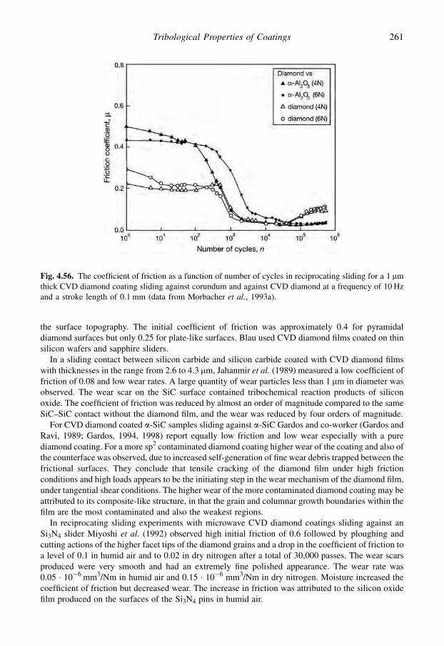
the surface topography. The initial coefficient of friction was approximately 0.4 for pyramidaldiamond surfaces but only 0.25 for plate-like surfaces. Blau used CVD diamond films coated on thinsilicon wafers and sapphire sliders.
In a sliding contact between silicon carbide and silicon carbide coated with CVD diamond filmswith thicknesses in the range from 2.6 to 4.3 mm, Jahanmir et al. (1989) measured a low coefficient offriction of 0.08 and low wear rates. A large quantity of wear particles less than 1 mm in diameter wasobserved. The wear scar on the SiC surface contained tribochemical reaction products of siliconoxide. The coefficient of friction was reduced by almost an order of magnitude compared to the sameSiC–SiC contact without the diamond film, and the wear was reduced by four orders of magnitude.
For CVD diamond coated a-SiC samples sliding against a-SiC Gardos and co-worker (Gardos andRavi, 1989; Gardos, 1994, 1998) report equally low friction and low wear especially with a purediamond coating. For a more sp2 contaminated diamond coating higher wear of the coating and also ofthe counterface was observed, due to increased self-generation of fine wear debris trapped between thefrictional surfaces. They conclude that tensile cracking of the diamond film under high frictionconditions and high loads appears to be the initiating step in the wear mechanism of the diamond film,under tangential shear conditions. The higher wear of the more contaminated diamond coating may beattributed to its composite-like structure, in that the grain and columnar growth boundaries within thefilm are the most contaminated and also the weakest regions.
In reciprocating sliding experiments with microwave CVD diamond coatings sliding against anSi3N4 slider Miyoshi et al. (1992) observed high initial friction of 0.6 followed by ploughing andcutting actions of the higher facet tips of the diamond grains and a drop in the coefficient of friction toa level of 0.1 in humid air and to 0.02 in dry nitrogen after a total of 30,000 passes. The wear scarsproduced were very smooth and had an extremely fine polished appearance. The wear rate was0.05 $ 10�6 mm3/Nm in humid air and 0.15 $ 10�6 mm3/Nm in dry nitrogen. Moisture increased thecoefficient of friction but decreased wear. The increase in friction was attributed to the silicon oxidefilm produced on the surfaces of the Si3N4 pins in humid air.
Fig. 4.56. The coefficient of friction as a function of number of cycles in reciprocating sliding for a 1 mmthick CVD diamond coating sliding against corundum and against CVD diamond at a frequency of 10 Hzand a stroke length of 0.1 mm (data from Morbacher et al., 1993a).
261Tribological Properties of Coatings

Extremely good wear resistance has been observed for a corundum ball in reciprocating slidingagainst a diamond coating deposited on cemented carbide by the hot filament technique (Blanpainet al., 1992, 1993). Even after five million cycles no measurable wear of the diamond coatingwas observed and the friction coefficient had dropped to a level below 0.05. Zeiler et al. (2000)also measured good tribological performance of a diamond coating sliding against alumina in areciprocating contact but the friction was higher, about 0.13 and the wear also relatively high.
4.5.2.9 Sliding against metals
As for bulk diamond, abrasive cutting and ploughing effects are more dominant when a hard diamondcoating slides on softer materials like metals. At the initial stage of the contact Blau et al. (1990) haveshown tribological topography effects. They observed microcutting of a 52100 steel surface by sharpdiamond points and found that steel debris tended to accumulate in pockets in the surface on thepyramidal and plate-like films. On the microcrystalline film, evidence for transfer of steel to thediamond surface was obtained. The initial coefficient of friction for the pyramidal topography wasapproximately 0.5, for the microcrystalline topography 0.3 and for the plate-like topography 0.2.
Diamond coatings deposited by the hot flame method may have very different surface topographiesthat influence friction in sliding. Hollman et al. (1994) tested 5 mm thick diamond coatings witha surface roughness of Ra¼ 0.53 mm in sliding against a flat tool steel surface at a speed of 0.062 m/s anda load increasing to 1000 N and measured coefficients of friction in the rage of 0.06 to 0.12. WhenHollman (1997) tested close to atomically smooth hot flame-deposited diamond coatings of a surfaceroughness of only Ra¼ 0.006 to 0.030 mm with a ball-on-disc device against different materials at a loadof 2 N and a speed of 0.1 m/s, the friction was very low, in the range of 0.055 to 0.095 for cementedcarbide, ball bearing steel and austenitic steel countersurfaces while it was considerably higher for Tiand Al counter surfaces, as shown in Fig. 4.57. The diamond coated ball radius was 6 mm and thecountersurfaces were flat. The initial friction was typically about 0.3 but dropped to the low value aftersome 5 to 10 m of sliding. Water slightly reduced the friction but the influence of both water and oil wasonly small. A very low wear of the diamond surfaces was detected, about 100 times lower than for steelagainst steel in lubricated sliding, and the countersurfaces displayed practically no wear at all.
4.5.2.10 Cutting tool contacts
A variety of diamond coated tools are today offered by commercial coaters at a reasonable cost. Theadvantage of diamond coatings in machining are the extreme hardness, good fatigue strength, high
Fig. 4.57. Friction coefficients for very smooth hot flame-deposited diamond surfaces with a roughness ofonly Ra¼ 0.03 mm sliding at 2 N load and 0.01 m/s speed against different counter material in variousenvironments. The materials are cemented carbide (CC), ball bearing steel (BBS), stainless steel (SS),titanium (Ti) and aluminium (Al) (data from Hollman, 1997).
262 Coatings Tribology
chemical inertness, high thermal conductivity, low friction, good resistance to abrasion, erosion andcorrosion. CVD-deposited diamond coatings of high quality are successfully deposited on cementedcarbide tool inserts. Even if other substrate materials have been tried there has been no large-scalecommercial utilization. Problems in the commercial manufacturing of diamond coatings are related tohigh deposition temperatures, poor adhesion, oxidation at high temperatures and high fabricationcosts (Erdemir and Donnet, 2005).
Diamond coatings are mainly used as cutting tools for non-ferrous alloys, such as aluminium,copper, magnesium and lead alloys; metal-matrix composites; non-metals, such as plastics, epoxyresins, fibre-reinforced polymers and other composites; semi-sintered ceramics, cold-pressedcemented carbides, graphite, silicon, hard rubbers and wood. Diamond coatings are more problematicto use for cutting ferrous metals because of the high chemical solubility of carbon in ferrous materialsat elevated temperatures, making diamond unsuitable for machining steels, cast iron and superalloys.The very high temperatures, around 1000�C, generated at the tool/chip interface, result in extremelyrapid wear of the diamond tool by chemical dissolution (Soderberg et al., 1991; Lux and Haubner,1992).
Another limitation for using diamond coatings more extensively on cutting tools has been thedifficulty in achieving good adhesion between the coating and the substrate. Methods to remove thecobalt from the surface of cemented carbide substrates (Anon., 1990) or to remove carbon (Saijo et al.,1990) have been suggested to solve this problem.
Soderberg et al. (1991) report that they have largely overcome the adhesion problem whenmachining Al–Si alloys by using silicon nitride or SiAlON substrates. In their experiments CVDdiamond films exhibited superior flank wear resistance as compared to conventional PCD tools. Theend of tool life was reached when the coating was worn through due to accelerated wear of the un-derlying substrates. Hence, the performance of CVD diamond coated tools is determined by the flankwear resistance and the thickness of the coating.
A considerable decrease in flank wear and an increase in lifetime have been achieved when usingCVD diamond coated cemented carbide, tungsten carbide and SiAlON tool inserts in cutting Al–Siand Al alloys (Shibuki et al., 1988; McCune et al., 1989; Saijo et al., 1990; Takatsu et al., 1990;Kikuchi et al., 1991; Yazu and Nakai, 1991; Alahelisten, 1994; Schmitt and Paulmier, 2004). The filmthicknesses were in the range 5 to 10 mm. Similar wear performance has also been observed whencutting hard carbon with CVD diamond coated tungsten carbide inserts (Saijo et al., 1990).
4.5.2.11 Erosive wear resistance
The erosion resistance of diamond coated components is excellent when optimal surface parametersare achieved. The thickness of the coating is one crucial parameter. A problem with a diamond coatedcomponent is that when its erosion resistance is overcome the coating may crack and quickly flake off,resulting in catastrophic failure.
Solid particle erosion testing of 10 mm thick diamond coatings deposited by microwave plasmaCVD on silicon, tungsten and Ti–6Al–4V substrates has shown excellent erosion resistance both with30� and 90� angles of particle attack and velocities of 4 and 15.5 m/s (Kral et al., 1993), as shown inFig. 4.58. The diamond coating increased the erosion resistance considerably for all coating–substratecombinations and the best erosion resistance was measured with silicon and tungsten substrates.Diamond films on silicon substrates eroded by a gradual chipping or cleavage of individual grainsuntil the coating was penetrated at a single location. Once a coating had been penetrated suddencatastrophic failure occurred.
The coating thickness was the crucial factor when Wheeler and Wood (1999) tested the erosionresistance of 10 to 47 mm thick CVD-deposited diamond coatings deposited on W and SiC substratesin water–sand slurry and high-velocity air–sand rigs with sand sizes of 135 to 235 mm diameter, in thevelocity range of 16 to 268 m/s and at 90� impact angle. Coating thicknesses of less than 20 mm were
263Tribological Properties of Coatings

insufficient to withstand erosion and failed catastrophically. However, in high-velocity erosion theerosion rate of 39 to 47 mm thick diamond coatings on tungsten was six times lower than for cementedtungsten carbide surfaces.
Good erosive wear protection and a clear correlation with coating thickness was measured fordiamond coatings deposited on cemented carbide substrates by the hot flame technique in erosion testswith SiC erosive particles of 121 to 423 mm diameter sizes, at velocities of 11 to 87 m/s and with a 90�
impact angle (Alahelisten et al., 1993; Hollman et al., 1994). A coating thickness of 6 mm was neededfor a wear protection that outperformed the erosion resistance of the reference materials that werecemented carbide, TiN/TiC and Al2O3/TiC coated cemented carbide samples. The product of theerodent mass and the velocity, called the impulse, needed for coating failure increased almost linearlywith coating thickness, as shown in Fig. 4.59.
4.5.2.12 Scales of diamond coating tribological mechanisms
From the above it can be seen that diamond or diamond coatings sliding against themselves or againstvarious materials may have extremely low friction down to the range of superlubricity, but the frictionmay also be very high in other conditions. The wear may be zero or it may also be very high. In someconditions there are environmental effects and in others they are negligible. In some conditions thesurface roughness is crucial and in others it can be neglected. How can all this be understood?
We believe that the key to an overall understanding of the tribological behaviour of diamond anddiamond coatings lies in the scaling effects. In the literature some experiments and theories relate tocontact conditions representative for macroscale contacts, others for microscale contacts and someothers for nanoscale contacts. This is illustrated in Fig. 4.60.
Fig. 4.58. Steady-state erosion rates for diamond coated and uncoated silicon, Ti–6Al–4V and tungsten,and as reference coatings thermally sprayed (ts) WC–Co on Inconel 718 and sputtered (sp) NiCrC onTi–6Al–4V, for different angles of particle attack and velocities (data from Kral et al., 1993).
264 Coatings Tribology
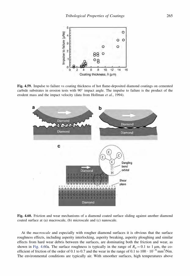
At the macroscale and especially with rougher diamond surfaces it is obvious that the surfaceroughness effects, including asperity interlocking, asperity breaking, asperity ploughing and similareffects from hard wear debris between the surfaces, are dominating both the friction and wear, asshown in Fig. 4.60a. The surface roughness is typically in the range of Ra¼ 0.1 to 1 mm, the co-efficient of friction of the order of 0.1 to 0.7 and the wear in the range of 0.1 to 100 $ 10�6 mm3/Nm.The environmental conditions are typically air. With smoother surfaces, high temperatures above
Fig. 4.59. Impulse to failure vs coating thickness of hot flame-deposited diamond coatings on cementedcarbide substrates in erosion tests with 90� impact angle. The impulse to failure is the product of theerodent mass and the impact velocity (data from Hollman et al., 1994).
Fig. 4.60. Friction and wear mechanisms of a diamond coated surface sliding against another diamondcoated surface at (a) macroscale, (b) microscale and (c) nanoscale.
265Tribological Properties of Coatings
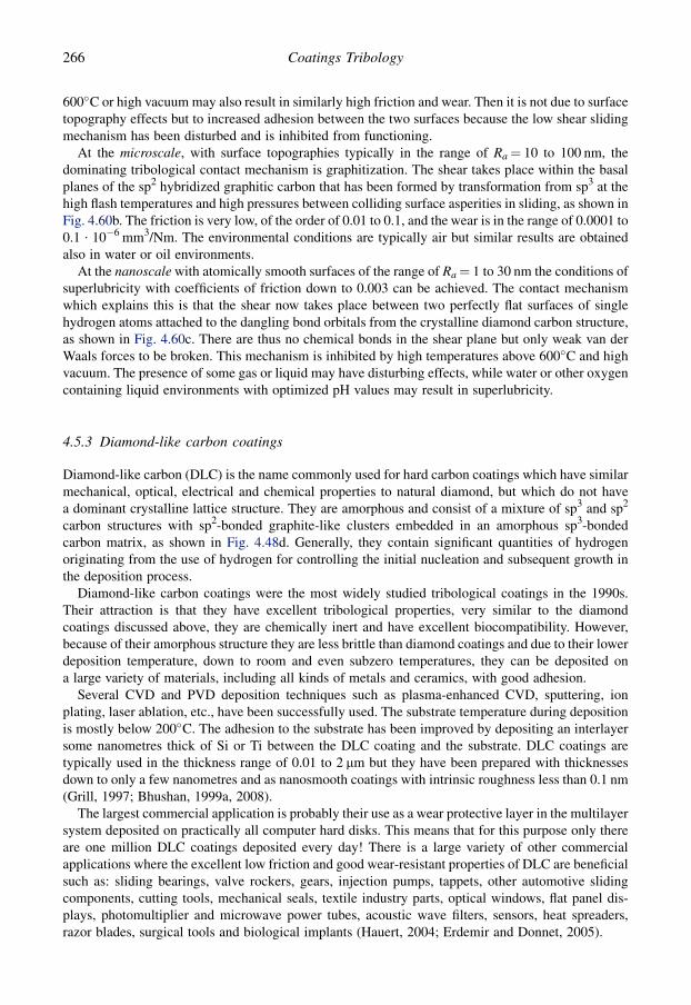
600�C or high vacuum may also result in similarly high friction and wear. Then it is not due to surfacetopography effects but to increased adhesion between the two surfaces because the low shear slidingmechanism has been disturbed and is inhibited from functioning.
At the microscale, with surface topographies typically in the range of Ra¼ 10 to 100 nm, thedominating tribological contact mechanism is graphitization. The shear takes place within the basalplanes of the sp2 hybridized graphitic carbon that has been formed by transformation from sp3 at thehigh flash temperatures and high pressures between colliding surface asperities in sliding, as shown inFig. 4.60b. The friction is very low, of the order of 0.01 to 0.1, and the wear is in the range of 0.0001 to0.1 $ 10�6 mm3/Nm. The environmental conditions are typically air but similar results are obtainedalso in water or oil environments.
At the nanoscale with atomically smooth surfaces of the range of Ra¼ 1 to 30 nm the conditions ofsuperlubricity with coefficients of friction down to 0.003 can be achieved. The contact mechanismwhich explains this is that the shear now takes place between two perfectly flat surfaces of singlehydrogen atoms attached to the dangling bond orbitals from the crystalline diamond carbon structure,as shown in Fig. 4.60c. There are thus no chemical bonds in the shear plane but only weak van derWaals forces to be broken. This mechanism is inhibited by high temperatures above 600�C and highvacuum. The presence of some gas or liquid may have disturbing effects, while water or other oxygencontaining liquid environments with optimized pH values may result in superlubricity.
4.5.3 Diamond-like carbon coatings
Diamond-like carbon (DLC) is the name commonly used for hard carbon coatings which have similarmechanical, optical, electrical and chemical properties to natural diamond, but which do not havea dominant crystalline lattice structure. They are amorphous and consist of a mixture of sp3 and sp2
carbon structures with sp2-bonded graphite-like clusters embedded in an amorphous sp3-bondedcarbon matrix, as shown in Fig. 4.48d. Generally, they contain significant quantities of hydrogenoriginating from the use of hydrogen for controlling the initial nucleation and subsequent growth inthe deposition process.
Diamond-like carbon coatings were the most widely studied tribological coatings in the 1990s.Their attraction is that they have excellent tribological properties, very similar to the diamondcoatings discussed above, they are chemically inert and have excellent biocompatibility. However,because of their amorphous structure they are less brittle than diamond coatings and due to their lowerdeposition temperature, down to room and even subzero temperatures, they can be deposited ona large variety of materials, including all kinds of metals and ceramics, with good adhesion.
Several CVD and PVD deposition techniques such as plasma-enhanced CVD, sputtering, ionplating, laser ablation, etc., have been successfully used. The substrate temperature during depositionis mostly below 200�C. The adhesion to the substrate has been improved by depositing an interlayersome nanometres thick of Si or Ti between the DLC coating and the substrate. DLC coatings aretypically used in the thickness range of 0.01 to 2 mm but they have been prepared with thicknessesdown to only a few nanometres and as nanosmooth coatings with intrinsic roughness less than 0.1 nm(Grill, 1997; Bhushan, 1999a, 2008).
The largest commercial application is probably their use as a wear protective layer in the multilayersystem deposited on practically all computer hard disks. This means that for this purpose only thereare one million DLC coatings deposited every day! There is a large variety of other commercialapplications where the excellent low friction and good wear-resistant properties of DLC are beneficialsuch as: sliding bearings, valve rockers, gears, injection pumps, tappets, other automotive slidingcomponents, cutting tools, mechanical seals, textile industry parts, optical windows, flat panel dis-plays, photomultiplier and microwave power tubes, acoustic wave filters, sensors, heat spreaders,razor blades, surgical tools and biological implants (Hauert, 2004; Erdemir and Donnet, 2005).
266 Coatings Tribology

The mechanical properties of hydrogen-containing amorphous DLC are hardness in the range of5 to 60 GPa, Young’s modulus of 60 to 400 GPa, fracture toughness of 1 to 12 MPa $ m0.5 andPoisson’s ratio of 0.2 to 0.4. The hardest amorphous DLC coating is a tetrahedrally bonded carbon (ta-C) with hardness in the range of 40 to 90 GPa and Young’s modulus of 200 to 900 GPa. Internalstresses are normally compressive and in the range of 0.2 to 3.6 GPa. The coefficient of friction forDLC is generally in the range of 0.02 to 0.4 and the wear rate 0.0001 to 1 $ 10�6 mm3/N $ m in normalair, while the coefficient of friction in a vacuum or inert environment is in the range of 0.001 to 0.02and the wear rate may be as low as 0.00001 $ 10�6 mm3/N $ m (Robertson, 1992b; Holmberg andMatthews, 1994; Tsui et al., 1995; Grill, 1997; Kodali et al., 1997; Gangopadhyay, 1998; Bhushan,1999a; Nastasi et al., 1999; Schaefer et al., 2000; Ronkainen, 2001; Erdemir, 2002, 2004a, b;Fujisawa et al., 2003; Singer et al., 2003; Gupta et al., 2004; Klaffke et al., 2004a; Hauert, 2004;Erdemir and Donnet, 2005; Klaffke et al., 2005a; Rha et al., 2005; VDI-Richtlinien, 2005; Neuvilleand Matthews, 2007; Donnet and Erdemir, 2008; Fontaine et al., 2008; Lemoine et al., 2008).
4.5.3.1 Microstructure and hardness
The CVD and PVD deposition techniques offer good possibilities to tailor DLC coatings with variousstructures corresponding to the required properties. The main categories of DLC coatings and theirabbreviations are (VDI-Richtlinien, 2005):
� a-C: hydrogen-free amorphous carbon coating,� ta-C: tetrahedral hydrogen-free amorphous carbon coating,� a-C:Me: metal-containing hydrogen-free amorphous carbon coating (Me¼W, Ti.),� a-C:H: hydrogenated amorphous carbon coating,� ta-C:H: tetrahedral hydrogenated amorphous carbon coating,� a-C:H:Me: metal-containing hydrogenated amorphous carbon coating (Me¼W, Ti.), and� a-C:H:X: modified hydrogenated amorphous carbon coating (X¼ Si, O, N, F, B.).
Since small quantities of hydrogen, e.g. from residual gases, can still be incorporated in the films evenwhen there is no use of hydrogen gas in the deposition process, a hydrogen limit of about 3 at.% isquoted (VDI-Richtlinien, 2005) as the transition between hydrogen-free and hydrogenated carboncoatings.
The most important structural parameters are the sp3/sp2 ratio and the hydrogen content in thecoating. The balance between them and the regions of the various DLC coatings is illustrated in theternary phase diagram in Fig. 4.61a. At higher temperatures a recrystallization of the carbon structureto graphite takes place and this transition depends on the sp3/sp2 ratio, as shown in Fig. 4.61b.
In hydrogenated amorphous diamond-like carbon coatings (a-C:H) the proportion of sp3 bonds inthe structure is typically in the range of 30 to 60% for hard coatings and in the range of 50 to 80% forsofter coatings. For the hard coatings the hydrogen content is in the range of 10 to 40% and for thesofter coatings 40 to 65%. Here hard coatings refer to hardness values of 10 to 40 GPa and softcoatings to hardness below 5 GPa (Franks et al., 1990; Ham and Lou, 1990; Hirvonen, 1991;Robertson, 1992a, b; Raveh et al., 1993; Neuville and Matthews, 2007). The influence of totalhydrogen content on surface microhardness of a-C:H coatings deposited in various plasma conditionsis shown in Fig. 4.62.
Non-hydrogenated amorphous diamond-like carbon coatings (a-C) typically have about 85 to 95%sp3 bonds in their carbon structure and the hydrogen content is often less than 1%. There are largevariations reported in their hardness, from 30 to 100 GPa, which is a range that covers coatings even ashard as diamond (Hirvonen, 1991; Robertson, 1992a, b; Ronkainen et al., 1993). The very hard a-Ccoatings are normally referred to as ta-C but they have also been referred to as amorphous diamond,because of their extreme hardness, and because their local structure is tetrahedral, as for diamond,even if their structure is disordered on a large scale (Green et al., 1989).
267Tribological Properties of Coatings

Molecular dynamic simulations have shown that the three-dimensional structure, not just the sp3/sp2 ratio, is important in determining the mechanical properties of the coatings (Gao et al., 2003).Particular orientations of sp2 ring-like structures create coatings with both high sp2 content and largeelastic constants. Coatings with graphite-like top layers parallel to the substrates have lower elasticconstants than coatings with large amounts of sp3-hybridized carbon. The layered structure of thehydrogen-free coatings results in a mechanical behaviour that influences the friction-to-load re-lationship. The atomic-scale structure of the coating at the interface has turned out to be of criticalimportance in determining the load at which tribochemical reactions and wear between the coatingand the counterface are induced. Unsaturated sp-hybridized atoms on the surface of a coating serve asinitiation points for such reactions, as shown in Fig. 4.63.
Fig. 4.61. (a) Ternary phase diagram for DLC coatings showing the balance of the sp3/sp2 ratio and thehydrogen content in the coating (after Ferrari and Robertson, 2000; Erdemir and Donnet, 2005). UNCDrefers to ultra-nanocrystalline diamond and HC to hydrocarbon. (b) Simplified overview of thermal sta-bility limits of different categories of hard carbon materials. The arrows indicate the effect of heating onchanges to the phases (after Neuville and Matthews, 2007).
268 Coatings Tribology

4.5.3.2 Deposition techniques
The most important feature, in addition to the excellent tribological properties, that makes this groupof coatings so interesting, is that they can be produced at low temperatures, even below room tem-perature. This is a considerable achievement compared to the diamond coatings normally produced at
Fig. 4.62. Surface microhardness (Hk) as a function of total hydrogen content (CH) in a-C:H diamond-likecoatings deposited in various plasma conditions: (A) CH4þH2 in rf or mwrf, (B) rf CH4, (C) mwrf CH4,(D) rf CH4þAr and (E) mwrf CH4þAr (data from Raveh et al., 1993).
Fig. 4.63. A hydrogen-terminated (H) diamond counterface in sliding contact with an amorphous carbonlayer (DLC) attached to a diamond substrate. Sliding-induced chemical reactions have occurred betweensp-hybridized film atoms and the counterface (from Gao et al., 2003 with permission). See Appendix B forcoloured picture.
269Tribological Properties of Coatings

temperatures in the range of 400 to 900�C, PVD TiN coatings in the range of 400 to 600�C and CVDcoatings in the range of 900 to 1100�C. The low coating temperature offers the possibility to coatsubstrates that cannot withstand high temperatures, such as polymers and heat-treated metals. On theother hand, diamond-like carbon coatings are not suitable for high-temperature applications becausethey are thermally unstable at temperatures above about 450�C. This makes them less suitable for useas coatings for cutting tools where the contact temperature between the chip and the insert can be up to1000�C, although as discussed in Chapter 7 there are some promising results reported in cutting testsusing DLC coated tools.
4.5.3.3 Temperature dependence
The diamond-like carbon structure is a metastable form and can only exist up to a certain temperaturelevel (Fig. 4.61b). Thermal graphitization of the graphite film takes place, starting from temperatures inthe range of 300 to 600�C, and may be accompanied by the effusion of hydrocarbons and hydrogen. Ashydrogenated DLC coatings are heated to temperatures above 300�C dehydrogenation transforms sp3
bonded carbon atoms into sp2 bonded atoms, resulting in a decrease in hardness and elastic modulus(Gangopadhyay, 1998). Hydrogen-free DLC coatings, on the other hand, are more temperature stable.Koskinen (1988) reported no change in hardness for hydrogen-free amorphous carbon coatings whenheated up to 600�C. The influence of temperature on the mechanical properties of the coatings will alsoinfluence their friction and wear behaviour. Erdemir and Donnet (2005) report how the wear rate is in-creased by four orders of magnitude as the temperature increased from 29 to 250�C, as shown in Fig. 4.64.
With increasing plasma deposition energy, the mass of the released molecules decreases and thethermal stability increases considerably. In a softer coating both the hydrogen and the hyrocarbonsdiffuse at a low temperature, while only hydrogen diffuses at a higher temperature for hard coatings(Franks et al., 1990). The consequence of such thermal instability was observed by Miyoshi (1991) asa sharp increase in the coefficient of friction from 0.2 to 0.8 when the ambient temperature in vacuumincreased from 500 to 600�C for an Si3N4 ball sliding over an a-C:H coating.
4.5.3.4 Intrinsic stresses
Diamond-like carbon coatings normally exhibit significant compressive in-plane internal stresses; inthe range of 0.2 to 3 GPa depending on the film thickness, but even higher values up to 5 GPa havebeen reported. They may be thermal stresses originating from the coating–substrate mismatch in
Fig. 4.64. Effect of temperature on wear performance of hydrogenated diamond-like carbon coatings(data from Erdemir and Donnet, 2005).
270 Coatings Tribology

thermal expansion, and intrinsic stresses originating from changes in the film density as the filmgrowth proceeds. In addition Raveh et al. (1993) have demonstrated the ability of DLC to accom-modate trapped gases as a principal cause for internal stresses, when Ar or other gases, such asunbonded hydrogen, are incorporated into voids or microstructural boundaries in the coatings.
These effects improve the coating hardness but also cause the DLC film to become more brittle.The intrinsic stresses increase with coating thickness and coatings thicker than 2 mm tend to be sostressed that they easily delaminate due to the high stresses (Ham and Lou, 1990; Gangopadhyay,1998). Modification of the film composition by adding Si or Ti into the coatings reduces the internalstresses, due to fewer interconnections in the random carbonaceous network, by a factor of two to fourand this allows the deposition of thicker films. The internal stresses can also be relieved by annealingin an oxygen-free environment. Grill et al. (1990) showed that annealing in vacuum for 4 hours at390�C reduced the internal stress from 1.34 GPa for the DLC film to 0.30 GPa without any significantchange in film structure. At higher annealing temperatures the films may start to graphitize and losetheir diamond-like properties.
Another approach to reduce the high intrinsic stresses in DLC coatings is to deposit them asmultinanolayers, with consecutive soft and hard DLC nanolayers. In general, a multilayer coating willexhibit lower intrinsic stresses, higher hardness and elastic modulus than the average values of theirtwo parent films. However, the influence was not as big as expected when Gupta and Meletis (2004)deposited six different 2 mm thick multinanolayers with consecutive soft and hard DLC nanolayerseach of 50 to 200 nm thickness. The internal stresses in the soft and hard parent a-C:H films were 0.7and 1.2 GPa, respectively, but the stresses in the six multilayer films varied from 0.8 to 1.5 GPa andwere on average slightly below 0.95 GPa, which would be the average of the internal stresses in bothconstituent films. The influence on the internal stresses was neither as large nor as clear as one wouldexpect. There are large variations in the internal stresses in DLC multilayers reported, varying from0.8 to 6 GPa. The internal stresses in DLC films have been reviewed by Pauleau (2008).
4.5.3.5 Adhesion to the substrate and interface layers
The effective adhesion determines the strength of the interface between the coating and the substrateand has a dominating influence on the wear properties and especially on the maximum load thesurface can sustain before delamination and failure. The effective adhesion depends on the strength ofthe adhesive bonds between the coating and the substrate. These bonds may be pre-stretched and thusweakened by intrinsic stresses in the coating system. The strength of the bonds between the coatingand the substrate is influenced by the substrate material and by the deposition method. Diamond-likecarbon coatings have a widely varying adhesion to different substrates. Good adhesion of DLCcoatings to carbide and silicide substrates has been found.
A wide variety of substrate materials were coated by rf plasma CVD by Ham and Lou (1990). Theyobserved that, of all materials coated, silicon was most effective as substrate material. It was virtuallyimpossible to remove the DLC from Si. The adhesion to most other substrates was good. However, noadhering films could be deposited on Au, Cu, W, or on stainless steel containing Cu. Other substratematerials tested were Al, Ni, Mo, GaAs, Ti, TiN, steel, stainless steel, Pyrex glass, quartz, ceramicsand Lexan.
The adhesion of 0.2 mm thick DLC coatings deposited by a pulsed arc discharge method on 19different substrate materials such as metals, ceramics and polymers was studied by a pull test, Vickersindentation and a scratch test by Koskinen et al. (1992). In general, materials with high affinity tocarbon had the best adhesion as shown in Fig. 4.65.
There are different ways of improving the adhesion of a coating to its substrate of which the use ofinterface layers is the most common. In general, coatings deposited by ion beam-assisted depositionor by cathodic arc discharge techniques do not require any interlayer for good film adhesion toaluminium alloys or steel because the high energy of the impacting ions provides good interfacial
271Tribological Properties of Coatings

mixing. However, coatings deposited by plasma-assisted CVD techniques often require an interlayerfor good film adhesion (Gangopadhyay, 1998). Si, Ti, TiN, TiC, Ni and Cr have been successfulinterlayer materials for improving the adhesion between the DLC coating and the substrate(Ronkainen et al., 1997; Vercammen et al., 2004; Maurin-Perrier et al., 2005).
Figure 4.66 shows how the adhesion of rf plasma-deposited DLC on cemented carbide can beconsiderably improved by using a TiC intermediate layer and low sputter-cleaning power (Vihersaloet al., 1993; Ronkainen et al., 1993, 1997). TiN has also been found to have an improving effect on thescratch adhesion of a-C:H layers to steel substrates (Holiday et al., 1992), though this result was notalways borne out in real sliding tests. This is because the scratch test does not accurately simulatea normal sliding contact and emphasizes the load support under the coating (Matthews and Eskildsen,1993; Ollivier and Matthews, 1993).
Hirvonen et al. (1992) have shown that the adhesion of pulse arc discharged a-C DLCs can beimproved when deposited on carbon steel substrates by combining ion bombardment with a siliconcarbide intermediate layer. This bombardment resulted in a mixed layer with a thickness of 1.2 to1.7 nm. The improvement in the adhesion was interpreted as originating from a chemical interactionbetween silicon and iron. Ion bombardment without an interlayer did not improve the adhesion.
An interlayer has two functions, one is to increase the bonding strength between the coating and thesubstrate and the other is to reduce the interfacial intrinsic stresses. The fulfilment of the first functiondoes not require a thick interface layer; a very thin one of some nanometres thickness may be enough.However, an interlayer can better accommodate the stresses at the coating/substrate interface.A thicker coating may also affect the load-carrying capacity of a coated surface and prevent plasticdeformation of the substrate. This is well illustrated by the experiments of Gangopadhyay et al. (1997)who deposited a series of successively thicker silicon interlayers between an, about 1.0 mm thick,amorphous hydrogenated carbon coating and an aluminium–silicon alloy substrate. Figure 4.67 showsthe measured coating durability, defined as time to coating failure, when sliding against steel balls, asa function of coating thickness. The thickness of the interface layer is the given coating thicknessminus 1 mm. A clear increase in coating durability was achieved with a thicker interlayer. The frictioncoefficient decreased from 0.36 to 0.12 with increasing thickness.
Fig. 4.65. The adhesion of a-C DLC coating to different substrate materials given as scratch test criticalload related to substrate hardness (data from Holmberg et al., 1994). The values marked with arrowsindicate values of adhesion when failure of substrate material occurred.
272 Coatings Tribology

4.5.3.6 Biocompatibility
Diamond-like carbon coatings are considered to be suitable for use in the biomedical field, particu-larly in orthopaedic implants. They can be made to adhere strongly to a range of materials used forbio-engineering and surgical purposes, including metals such as stainless steel, titanium, cobalt–chrome and various plastics including polyethylene and polyurethane. The diamond-like coating canbe used as a chemically protective, impermeable layer on such materials in a biological environment.Thomson et al. (1991) have carried out in vitro tests with mouse macrophage cells and fibroblast cells.No inflammatory response or loss of cell integrity by contact with the carbon coating occurred.Morphological examination confirmed the biochemical results of no cellular damage. Other studies onthe biocompatibility of DLC have been reviewed by Cui and Li (2000). Very promising results havebeen reported by Ajayi et al. (2005) on the tribological behaviour of amorphous carbon coatedstainless steel sliding against uncoated stainless steel to replace the commonly used stainless steel
Fig. 4.66. Adhesion measured as critical load for rf plasma diamond-like carbon coatings on cementedcarbide substrates with different intermediate layers and for different sputtering powers (after Vihersaloet al., 1993).
Fig. 4.67. Durability of a DLC coated aluminum–silicon alloy surface with silicon interlayers of suc-cessively increasing thicknesses while the thickness of the DLC coating is all the time constant, about1 mm (data from Gangopadhyay et al., 1997).
273Tribological Properties of Coatings

against UHMWPE in artificial hip joint implants. The wear of the DLC coating was four orders ofmagnitude lower than for the UHMWPE surface and no wear of the uncoated stainless steel countersurface was observed.
4.5.3.7 Surface graphitization
As for diamond, it has been speculated that the very low coefficient of friction of diamond-like carboncoatings in sliding contacts is due to graphitization and the formation of a thin graphitic layer on top ofthe hard coating (Jahanmir et al., 1989; Erdemir et al., 1991c; Klaffke et al., 1992; Holiday et al.,1992; Holmberg and Matthews, 1994). Some uncertainty on this mechanism has been due to theproblem of managing to detect clear traces of graphite on the sliding surfaces, although many havepostulated this phenomenon.
Erdemir et al. (1991c) slid a sapphire pin in argon over an old wear track on a DLC coating that wasformed in humid air. The initial friction coefficient was about 0.09 and decreased after about 100passes to a value of 0.03. When they slid the same pin over a new wear track the friction coefficientlevel of 0.03 was reached after only ten passes. The authors explained this behaviour with thehypothesis that a thin graphitic film is formed on the contact interface of the DLC coating duringsliding in humid air. A decrease in friction with increasing humidity is typical for graphite.
Wei et al. (1993) found a very clear indication of the formation of graphite in the wear track ona diamond-like a-C:H coated disc after a 100 million cycle rolling contact fatigue test. The growth inthe Raman peak, which corresponds to a disordered mode in the small graphite crystallite, comparedto that measured outside the wear track implies that the effect of fatigue wear of the coating is to breakthe interlayer bonds which characterize hard-carbon films, thereby allowing the top layer of thecoating material to return to graphite which is the more stable carbon form.
A number of further studies have pointed to the appearance of graphite in the wear tracks. Theyhave also shown another important contact mechanism that influences friction and wear – the for-mation of a carbon-rich transfer layer on the countersurface (Hirvonen et al., 1990a, b; Ronkainenet al., 1993; Grill, 1997; Wei and Komvopoulos, 1997; Voevodin and Zabinsky, 2000; Ronkainen,2001; Scharf and Singer, 2003a, b, c, 2008; Singer et al., 2003; Zhang et al., 2003b; Field et al., 2004;Erdemir and Donnet, 2005; Kano et al., 2005; Konca et al., 2005; Neuville and Matthews, 2007). Thistransfer layer covers more or less completely the countersurface giving it a smooth load-carryingplatform ideal for low shear in combination with the graphitized top layer of the DLC coating, asshown in Fig. 4.68. Transfer layers consisting of carbon, oxygen, chromium, aluminium and iron havebeen observed. The result is that the friction occurs between two surfaces with amorphous carbon toplayers, which have a structural chemistry quite different from the original DLC coating, but similar tothat of crystalline graphite.
The process when the transfer layer is built up on the countersurface has very convincingly beenillustrated by in situ experiments with a transparent sapphire hemisphere of 6.35 mm diameter sliding
Fig. 4.68. In a steel or ceramic surface sliding against a diamond-like carbon surface a transfer layer isformed on the steel/ceramic surface and the shear is taking place between two amorphous carbon toplayers which are similar to crystalline graphite.
274 Coatings Tribology

against an amorphous DLC film by Singer and co-workers (Singer et al., 2003). In sliding tests in dryair of RH¼ 4% at a speed of 0.001 m/s, load of 6 N and a mean Hertz stress of 0.7 GPa the coefficientof friction dropped rapidly from an initially high value of 0.25 down to 0.05 and then remainedconstant. A transfer film of 100 to 200 nm thickness was built up on the sapphire surface. As the filmbecame thicker and patchy its Raman spectra showed peaks characteristic of a graphite-like transferfilm. Similar tests were performed at higher stresses, up to 1.1 GPa and in moist air. The frictioncoefficient in humid air was about 20% higher than in dry air. The transfer films were thicker and thecoefficients of friction were more stable in moist air.
The graphitization process in hydrogenated a-C:H and in hydrogen-free ta-C carbon coatings wasstudied by Ronkainen and co-workers (Ronkainen et al., 1996, 1998, 1999b, c, 2001; Ronkainen,2001). They found clear evidence of graphite formation using micro-Raman in the a-C:H coating weartrack while the amount of graphite detected in the wear track of the ta-C coating was smaller aftertribotesting in the same conditions. They also calculated the flash temperatures for both contacts withsmooth surfaces. In low-load and low-speed conditions of 5 N and 0.1 m/s, resulting in a high co-efficient of friction up to 0.4 and high wear rate up to 0.2 $ 10�6 mm3/Nm, the calculated flashtemperatures were generally less than 100�C for the a-C:H coating sliding against alumina or steelballs. On the other hand, in high-load and high-speed conditions of 40 N and 3 m/s, resulting in a lowcoefficient of friction of 0.1 and lower wear rate of 0.2 $ 10�6 mm3/Nm, the calculated flash tem-peratures were about 350�C. The calculations showed much higher flash temperatures for the ta-Ccoating, up to 750�C.
As most contacts have some level of surface roughness with higher pressures at the asperitiestemperatures as high as 350�C can normally easily be reached at asperity tops. At this temperature,out-diffusion of hydrogen occurs in the a-C:H film. After hydrogen out-diffusion, the sp3 structuremay be transformed to an sp2 structure and forms graphite. Thus the graphite would be formed on thetop of the asperities to provide low friction. Graphite requires hydrogen to provide low-frictionproperties and this may be provided from the environmental humidity, water or from the out-diffusedhydrogen that is provided in larger amounts from a-C:H coatings but only very sparsely from ta-Ccoatings. Important conclusions are that the graphitization process is enhanced by sliding at higherloads and higher speeds and ta-C coatings have an increased need for receiving hydrogen from theenvironment to provide low friction and low wear.
In a relatively slow graphitization process of smooth and dense DLC coatings the graphitization takesplace mainly on the top layer of the coating. However, if the graphitization process is very rapid, as it maybe at high temperatures, then the carbon material will not only be transformed into amorphous graphiticcarbon at the surface, but also in the bulk of the coating and may also affect the coating-to-substrateinterface underneath the coating. This may reduce the mechanical strength of the bulk and the coatingmaterials and result in increased friction and wear (Neuville and Matthews, 2007).
The very good tribological behaviour of hard carbon-based coatings, with a dense and amorphousstructure dominated by almost entirely sp2 bondings, was considered to be due to the formation ofa graphite-like lubricious film between the coating and the counterpart in ball-on-disc testing (Fieldet al., 2004). A tungsten carbide 5 mm diameter ball was slid against the coating at loads of 40 and80 N. The coefficient of friction was initially about 0.15 but decreased to a steady-state value of 0.05to 0.07 and the wear rate was 0.021 to 0.043 $ 10�6 mm3/Nm. The authors suggest that also reor-ientation and recrystallization of the coating top layer takes place so that the basal planes becomeparallel to the sample surface. Higher normal loads would result in more reorientation and lowerfriction, as was observed.
4.5.3.8 Effect of hydrogen
The hydrogen content in a diamond-like carbon coating has a most significant influence on itshardness, modulus of elasticity, density and the sp3/sp2 ratio (Dunlop et al., 1991). The presence of
275Tribological Properties of Coatings

hydrogen is also important for the development of favourable friction conditions in diamond and DLCcoatings according to the dangling bond orbital and graphitization mechanisms described earlier. Thedecrease in microhardness for a variety of DLC coatings with increasing hydrogen content in thecoating is shown in Fig. 4.62 (Raveh et al., 1993; Gupta et al., 2004). The influence of hydrogencontent in the coating as well as the presence of hydrogen in the surrounding environment has beenshown by several studies (Ronkainen et al., 1993; Andersson et al., 2003b; Fontaine et al., 2004;Erdemir and Donnet, 2005; Li et al., 2007; Borodich et al., 2008; Ronkainen and Holmberg, 2008).The coefficients of friction and wear rates for DLC coatings derived from different carbon sourceswith various hydrogen-to-carbon (H/C) ratios are shown in Fig. 4.69. For higher hydrogen content inthe coating, the surface is covered by hydrogen atoms, leading to weak van der Waals bonds betweenthe sliding surfaces. For lower hydrogen content, on the other hand, there are not enough hydrogenatoms to shield the strong interactions between the free orbitals of carbon bonds.
In pin-on-disc tests Ronkainen et al. (1993) have shown that, in a load range of 5 to 40 N anda sliding velocity range of 0.1 to 3 m/s, the coefficient of friction for a steel pin sliding against an rfplasma a-C:H coating is in the range 0.10 to 0.42 and against a pulse arc discharge a-C coating is in therange 0.14 to 0.23. Figure 4.70 shows the results. Corresponding friction coefficient ranges for anAl2O3 counterface were 0.02 to 0.13 for a-C:H and 0.10 to 0.14 for a-C. The wear rate of the coateddisc was smaller for the a-C coating but the wear rate of the counterface was smaller for the a-C:Hcoating. The a-C:H coating had a hydrogen content of 26 at.% and the a-C coating less than 1 at.%.
4.5.3.9 Topography and its influence on friction and wear
The amorphous structure of the diamond-like carbon coatings does not produce the sharp peak to-pography that the facetted structure of some diamond coatings may result in. The DLC coatings aregenerally smooth and the roughness of the coated surface is significantly influenced by the roughnessof the substrate. Depending on the deposition technique and the coating thickness the surfaceroughness after deposition may be unchanged, or increased or decreased, by some 20 to 50%.
Fig. 4.69. Coefficients of friction and wear rates in sliding in dry nitrogen for DLC coatings derived fromdifferent carbon sources with various hydrogen-to-carbon (H/C) ratios (after Erdemir and Donnet, 2005).
276 Coatings Tribology

The surface roughness and topography is still a very important factor influencing its tribologicalperformance due to the hardness of the DLC coated surface. A rough surface may scratch thecountersurface resulting in high friction and wear whereas a very smooth surface contact may increasethe adhesion between the surfaces and have a similar effect. Thus the challenge is to find the optimalsurface roughness for the contacting surfaces to achieve optimal friction and wear performance.
The vast majority of the investigations on carbon coatings have been made on coatings deposited onvery smooth polished substrates. In large-scale production, however, the smoothing can be both timeconsuming and costly. On a macroscale both the friction and wear normally increase with surfaceroughness. In ball-on-disc tests with 1.3 mm thick PACVD coated diamond-like carbon coatings on
Fig. 4.70. Coefficient of friction for a steel pin sliding over (a) a hydrogenated a-C:H DLC coating and (b)a hydrogen-free a-C DLC at different loads and speeds. The coating thickness was 0.5 mm and the sub-strate material was stainless steel AISI 440B (after Ronkainen et al., 1993).
277Tribological Properties of Coatings

tool steel surfaces in the surface roughness range of Ra¼ 0.04 to 0.7 mm sliding against tungstencarbide balls of 6.3 mm diameter at a speed of 0.05 m/s and at loads of 20 to 40 N in dry air ofRH¼ 7% Jiang and Arnell (2000) measured a slight increase in the wear rate from 0.1 to0.5 $ 10�6 mm3/Nm, as shown in Fig. 4.71. The frictional behaviour was not apparently affected.After deposition the surface roughness of the coating was approximately half of the original substratesurface roughness, which was in the range of Ra¼ 0.08 to 1.15 mm. A transition was observed atthe roughness of 0.93 mm, then the wear increased rapidly and the wear mechanisms changed fromadhesion to chip and flake formation and fragmentation of the coating possibly including plasticyielding.
A larger effect of surface roughness on wear and especially on friction was measured by Svahnet al. (2003) for magnetron sputtered doped 1.2 mm thick a-C:W and 3.5 mm thick a-C:Cr diamond-like carbon coatings deposited on steel with surfaces in the roughness range of Ra¼ 0.007 to 0.39 mm.The surface roughness after deposition was unchanged for the a-C:W coating and increased by 20%for the a-C:Cr coating. In ball-on-disc test sliding with a speed of 0.07 m/s, load of 4 N and at RH¼ 30to 40% against steel balls of 3 and 9 mm diameter there was a clear surface roughness-related increasein the coefficient of friction from 0.06 to 0.21 for the small ball with high contact pressure and from0.11 to 0.31 for the larger ball with lower pressure with the a-C:W coating, as shown in Fig. 4.72a. Thewear rate increased from 0.2 to 0.5 $ 10�6 mm3/Nm with roughness, as shown in Fig. 4.72b. Theroughness influence of the a-C:Cr coating on friction was slightly smaller, an increase from 0.14 to0.32 was observed while the increase in wear rate was larger, it increased from 0.1 to 1 $ 10�6 mm3/Nm in the same conditions. The observed wear mechanisms were mainly gentle polishing of surfacepeaks where larger grooves collected wear debris. Some fatigue pits were found in the a-C:Cr coatingdeposited on rougher surfaces. The increase in friction with surface roughness is in this case notconsidered to be due to surface peaks ploughing in the steel countermaterial, since ball wear was verysmall compared to coating wear. The reason for the higher wear for rougher surfaces may be that thescratches are filled with oxidized coating material and the shearing of this third body material causeshigher friction.
The effect of surface roughness on friction and wear may be the opposite. Several investigationswith microscale smooth contacts have shown that a textured surface with some roughness candecrease friction when DLC is sliding against alumina, steel, silicon and sapphire surfaces compared
Fig. 4.71. The effect of surface roughness of a DLC coated surface on the wear rate of diamond-likecarbon coatings (data from Jiang and Arnell, 2000).
278 Coatings Tribology

to a very smooth surface (Zhou et al., 2000; Ahmed et al., 2003; Bandorf et al., 2003), but also theopposite effect has been reported (Erdemir, 2004b). This shows that to understand the influence ofsurface roughness on friction and wear a thorough investigation of the prevailing contact mechanismis needed.
4.5.3.10 Humidity dependence
In non-oxidizing controlled environments like vacuum, argon or dry nitrogen the tribologicalbehaviour of diamond-like carbon coatings is often similar to that of bulk diamond. However, watervapour influences the DLC coating and in humid air the coating behaves more like bulk graphite(Miyoshi, 1990; Erdemir et al., 1991c; Ronkainen and Holmberg, 2008). It is well documented thatgraphite requires moisture or other vapours to achieve low friction and low wear. The adsorbed vapourcovers the edge sites, thereby lowering the surface energy and reducing the adhesion to other surfaces(Singer, 1989).
Covalent bonds or s-bonds cause the strongest interactions across sliding diamond and DLCcoatings. In ultra-high vacuum when the s-bonds of surface carbon atoms are exposed and free toform strong covalent bonding across the surfaces, the coefficient of friction may be even above 1.0. Ifmoisture or gaseous species such as oxygen, hydrogen, fluorine, etc., are introduced the coefficient offriction of the diamond or hydrogen-free DLC surface drops to as low as 0.05, presumably due to thepassivation of the s-bonds and elimination of the strong covalent interaction across the slidinginterfaces (Erdemir et al., 2000).
However, it can be confusing to try to find answers from the literature on how the humidity in-fluences friction and wear for DLC coatings. There are several investigations showing an increase infriction and wear with increasing humidity (Gangopadhyay, 1998; Andersson et al., 2003a; Zhanget al., 2003b; Park et al., 2004; Tanaka et al., 2004a, b; Erdemir and Donnet, 2005; Klafke et al.,2005a), but there are also several showing a decrease with humidity (Andersson et al., 2003a;Tanaka, 2004a, b; Klafke et al., 2005a) and then again others showing really no influence at all(Miyoshi, 1998; Klafke et al., 2005a). These investigations are all performed in very competent
Fig. 4.72. Influence of surface roughness of an a-C:W coated steel surface sliding against steel balls with9 and 3 mm diameter at 0.07 m/s speed and 4 N load (a) on the coefficient of friction and (b) on the wearrate (data from Svahn et al., 2003).
279Tribological Properties of Coatings

laboratories so there is really no doubt about the reliability of the measurements. We believe that theexplanation is more due to the fact that there are several mechanisms related to sliding DLC surfacesthat have a humidity influence, and these effects are sometimes contradictory.
The explanation relating to a specific humidity behaviour lies with the dominating contactmechanisms in that specific experimental setup. The following mechanisms of humidity influence onDLC coatings have been suggested:
� the presence of moisture or adsorbed gases is required for low friction of graphitized top layers oncoatings,� the addition of small amounts of elemental species, such as N, F, Si, Ti, etc., into the DLC coatings
may reduce their tribological sensitivity to humidity,� high relative humidity can interfere negatively with the transfer film formation ability on steel
surfaces,� hydrogen is required for superlubricity based on the dangling bond orbital mechanism for atomi-
cally smooth surfaces; adding water destroys the superlubricity conditions,� addition of moisture passivates strong covalent bonds between surfaces in ultra-high vacuum and
the friction decreases,� at high humidity the saturation of microcontacts with water molecules can take place and during
sliding the water molecules exert a force across the opposing surfaces resulting in higher friction, and� in DLC coatings sliding against steel in increased humidity results in increased oxidation of the
steel surface and incorporation of Fe in the wear debris and increased friction.
Some general conclusions from the published work can be summarized as follows:
� highly hydrogenated DLC coatings have a low coefficient of friction in dry air and inert gases, evendown to 0.003 when sliding against themselves; in humid air their coefficient of friction may in-crease to above 0.2 while sliding against themselves, metals or ceramics,� hydrogen-free DLC coatings have low coefficient of friction in humid environments, down to 0.05;
in dry air or vacuum it may be very high, in the range of 0.3 to 0.6,� adding water normally decreases the coefficient of friction of hydrogen-free DLC coatings, to
values below 0.1; adding water to hydrogenated DLC coatings may in some cases increase thefriction but in others the coefficient of friction may drop to very low values around 0.01, and� the coefficient of friction remains very low in contacts with DLC sliding on diamond over a wide
relative humidity range.
The wear rate correlates generally with the behaviour of friction for DLC coatings. A collection ofpublished values for coefficients of friction and wear rates for diamond, various diamond-like carbon,graphite and polymeric coatings is presented in Table 4.1.
The very low coefficient of friction, often below 0.05, when a steel slider slides over a hydrogenatedDLC surface in dry air gradually increases with increasing humidity and reaches values in the range of0.15 to 0.3 at relative humidities close to 100% (Enke et al., 1980; Memming et al., 1986; Frankset al., 1990). Ronkainen and Holmberg (2008) have reviewed the environmental and thermal effectson the tribological performance of DLC coatings and they show the different influences of humidityon different categories of DLC coatings and the mechanisms controlling their tribological perfor-mance as presented in Fig. 4.73. The different mechanisms influencing on the frictional behaviour ofhydrogenated and hydrogen-free DLC coatings in different humidity environments have beendiscussed by Meunier et al. (2005), Li et al. (2007) and Liu et al. (2007).
4.5.3.11 Sliding against metals
A transfer layer is often formed on a steel surface when it slides over a diamond-like carbon coatingand the process of layer formation has a crucial influence on the friction and wear properties.
280 Coatings Tribology

Table 4.1. Friction coefficients and wear rates collected from the literature for diamond, diamond-like carbon, graphite and polymer coatings.
Diamondcoatings
Hydrogen-freeDLC
HydrogenatedDLC
Modified/dopedDLC
Graphitecoatings
References used
Structure CVD diamond a-Cta-C
a-C:Hta-C:H
a-C:Mea-C:H:Mea-C:H:XMe¼W,Ti..x¼ Si,O,N,F,B.
Andersson et al. (2003 a, b);Donnet (1998); Erdemir (2004a,b); Field et al. (2004); Fontaineet al. (2004); Gangopadhyay(1998); Grill (1997); Grillo andField (2003); Harris (1997);Hirvonen et al. (1990a); Klafkeet al. (2005a); Konca et al.(2003); Koskinen et al. (1992);Miyoshi (1998); Miyoshi et al.(1992); Park et al. (2004);Ronkainen et al. (1993, 1996);Ronkainen and Holmberg(2008); Ronkainen (2001); Svahnet al. (2003); Tanaka et al.(2004a, b); Voevodin andZabinski (2000); Zhang et al.(2003b)
Atomic structure sp3 sp2 and sp3 sp2 and sp3 sp2 and sp3 sp2
Hydrogen content – >1% 10–50%m in vacuum 0.02–1 0.3–0.8 0.007–0.05 0.03 –m in dry N2 0.03 0.6–0.7 0.001–0.15 0.007 –m in dry air 5–15% 0.08–0.1 0.6 0.025–0.22 0.03 0.05–0.07m in humidair 15–95%
0.05–0.15 0.05–0.23 0.02–0.5 0.03–0.4 0.05
m in water 0.002–0.08 0.07–0.1 0.01–0.7 0.06 –m in oil – 0.03 0.1 0.1K in vacuum 1–1000 60–400 0.0001 – –K in dry N2 0.1–0.2 0.1–0.7 0.00001–0.1 – –K in dry air 5–15% 1–5 0.3 0.01–0.4 – 0.02–0.04K in humidair 15–95%
0.04–0.06 0.0001–400 0.01–1 0.1–1 –
K in water 0.0001–1 – 0.002–0.2 0.15 0.01–0.05K in oil – – – 0.1 –m¼ coefficient of friction; K¼wear rate (10�6 mm3/Nm)
28
1T
ribo
log
ical
Pro
perties
of
Co
atin
gs
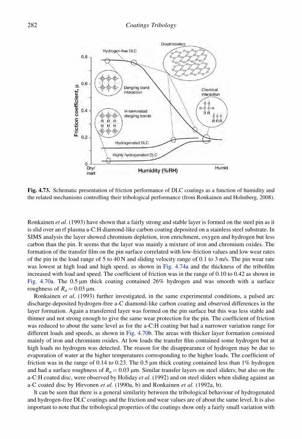
Ronkainen et al. (1993) have shown that a fairly strong and stable layer is formed on the steel pin as itis slid over an rf plasma a-C:H diamond-like carbon coating deposited on a stainless steel substrate. InSIMS analysis the layer showed chromium depletion, iron enrichment, oxygen and hydrogen but lesscarbon than the pin. It seems that the layer was mainly a mixture of iron and chromium oxides. Theformation of the transfer film on the pin surface correlated with low-friction values and low wear ratesof the pin in the load range of 5 to 40 N and sliding velocity range of 0.1 to 3 m/s. The pin wear ratewas lowest at high load and high speed, as shown in Fig. 4.74a and the thickness of the tribofilmincreased with load and speed. The coefficient of friction was in the range of 0.10 to 0.42 as shown inFig. 4.70a. The 0.5 mm thick coating contained 26% hydrogen and was smooth with a surfaceroughness of Ra¼ 0.03 mm.
Ronkainen et al. (1993) further investigated, in the same experimental conditions, a pulsed arcdischarge-deposited hydrogen-free a-C diamond-like carbon coating and observed differences in thelayer formation. Again a transferred layer was formed on the pin surface but this was less stable andthinner and not strong enough to give the same wear protection for the pin. The coefficient of frictionwas reduced to about the same level as for the a-C:H coating but had a narrower variation range fordifferent loads and speeds, as shown in Fig. 4.70b. The areas with thicker layer formation consistedmainly of iron and chromium oxides. At low loads the transfer film contained some hydrogen but athigh loads no hydrogen was detected. The reason for the disappearance of hydrogen may be due toevaporation of water at the higher temperatures corresponding to the higher loads. The coefficient offriction was in the range of 0.14 to 0.23. The 0.5 mm thick coating contained less than 1% hydrogenand had a surface roughness of Ra¼ 0.03 mm. Similar transfer layers on steel sliders, but also on thea-C:H coated disc, were observed by Holiday et al. (1992) and on steel sliders when sliding against ana-C coated disc by Hirvonen et al. (1990a, b) and Ronkainen et al. (1992a, b).
It can be seen that there is a general similarity between the tribological behaviour of hydrogenatedand hydrogen-free DLC coatings and the friction and wear values are of about the same level. It is alsoimportant to note that the tribological properties of the coatings show only a fairly small variation with
Fig. 4.73. Schematic presentation of friction performance of DLC coatings as a function of humidity andthe related mechanisms controlling their tribological performance (from Ronkainen and Holmberg, 2008).
282 Coatings Tribology

experimental parameters and the DLC coating can thus be considered as robust from a design point ofview.
A considerable number of later studies on friction and wear in DLC coated surfaces sliding againststeel provide much additional data that in general is in agreement with the above observations (e.g.Erdemir et al., 1995; Gangopadhyay, 1998; Singer, 1998; Podgornik, 2001; Ronkainen, 2001; Ahmedet al., 2003; Fujisawa et al., 2003; Klafke et al., 2004a; Park et al., 2004; Podgornik et al., 2006b; Choet al., 2005; Klafke, 2005; Maurin-Perrier et al., 2005; Fontaine et al., 2008). Friction and wear datafrom ball-on-disc experiments with a variation of DLC coatings sliding against different metal sur-faces is found in Klafke et al. (2004b, 2005a) and Blanpain et al. (1993).
4.5.3.12 Sliding against ceramics
For hydrogen-free DLC films (a-C) deposited on silicon nitride (Si3N4) produced by PVD ion-beamdeposition, Hirvonen et al. (1990a) observed a very low coefficient of friction of 0.06 in a slidingcontact against silicon nitride, as shown in Fig. 4.75. This is considerably lower than for the samecoating sliding in the same conditions against metals, when it was 0.14. However, the contact
Fig. 4.74. Wear rates at different loads and speeds from sliding contacts with (a) a steel pin sliding on(b) a hydrogenated a-C:H diamond-like coating, and (c) a steel pin sliding on (d) a hydrogen-free a-Cdiamond-like coating. Coating thicknesses were 0.5 mm and substrate material was stainless steel AISI440B (after Ronkainen et al., 1993).
283Tribological Properties of Coatings
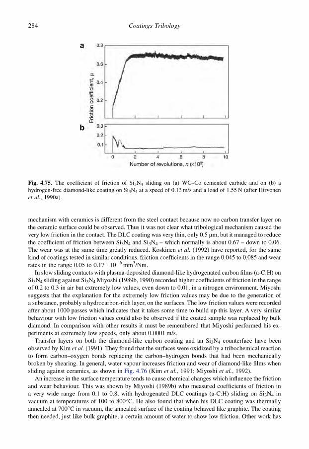
mechanism with ceramics is different from the steel contact because now no carbon transfer layer onthe ceramic surface could be observed. Thus it was not clear what tribological mechanism caused thevery low friction in the contact. The DLC coating was very thin, only 0.5 mm, but it managed to reducethe coefficient of friction between Si3N4 and Si3N4 – which normally is about 0.67 – down to 0.06.The wear was at the same time greatly reduced. Koskinen et al. (1992) have reported, for the samekind of coatings tested in similar conditions, friction coefficients in the range 0.045 to 0.085 and wearrates in the range 0.05 to 0.17 $ 10�6 mm3/Nm.
In slow sliding contacts with plasma-deposited diamond-like hydrogenated carbon films (a-C:H) onSi3N4 sliding against Si3N4 Miyoshi (1989b, 1990) recorded higher coefficients of friction in the rangeof 0.2 to 0.3 in air but extremely low values, even down to 0.01, in a nitrogen environment. Miyoshisuggests that the explanation for the extremely low friction values may be due to the generation ofa substance, probably a hydrocarbon-rich layer, on the surfaces. The low friction values were recordedafter about 1000 passes which indicates that it takes some time to build up this layer. A very similarbehaviour with low friction values could also be observed if the coated sample was replaced by bulkdiamond. In comparison with other results it must be remembered that Miyoshi performed his ex-periments at extremely low speeds, only about 0.0001 m/s.
Transfer layers on both the diamond-like carbon coating and an Si3N4 counterface have beenobserved by Kim et al. (1991). They found that the surfaces were oxidized by a tribochemical reactionto form carbon–oxygen bonds replacing the carbon–hydrogen bonds that had been mechanicallybroken by shearing. In general, water vapour increases friction and wear of diamond-like films whensliding against ceramics, as shown in Fig. 4.76 (Kim et al., 1991; Miyoshi et al., 1992).
An increase in the surface temperature tends to cause chemical changes which influence the frictionand wear behaviour. This was shown by Miyoshi (1989b) who measured coefficients of friction ina very wide range from 0.1 to 0.8, with hydrogenated DLC coatings (a-C:H) sliding on Si3N4 invacuum at temperatures of 100 to 800�C. He also found that when his DLC coating was thermallyannealed at 700�C in vacuum, the annealed surface of the coating behaved like graphite. The coatingthen needed, just like bulk graphite, a certain amount of water to show low friction. Other work has
Fig. 4.75. The coefficient of friction of Si3N4 sliding on (a) WC–Co cemented carbide and on (b) ahydrogen-free diamond-like coating on Si3N4 at a speed of 0.13 m/s and a load of 1.55 N (after Hirvonenet al., 1990a).
284 Coatings Tribology

shown, however, that rapid thermal annealing has only a minimal effect on the coefficients of frictionboth in humid air and in dry nitrogen but the wear rates are strongly dependent on the annealingtemperature and the moisture in the environment (Wu et al., 1992).
The formation of a strong and low shear-strength tribofilm has been observed to have a consider-able effect when Al2O3 pins slide over a diamond-like carbon coated surface. This was investigated byRonkainen et al. (1993) with the same coatings and experimental setup as referred to earlier withmetal counterfaces. For hydrogenated a-C:H DLC coatings they found that a transparent layer wasformed on the pin wear surface and the thickness of the film seemed to increase with higher loads andsliding velocities. Simultaneously, the coefficient of friction decreased drastically from 0.13, corre-sponding to 5 N and 0.1 m/s, to 0.02, corresponding to 22 N and 1.5 m/s, when the normal force andthe sliding velocity were increased. On the other hand, both the pin and the disc wear increased athigher normal forces. Alumina was transferred to the surface of the disc wear track.
The hydrogen-free a-C DLC coating behaved in a very similar way. The coefficient of friction wasslightly higher, in the range of 0.10 to 0.14, and extremely low values were not reached. The wear ofthe pin was slightly higher but the disc was worn less. The tribofilm formed on the pin was weaker andcould not protect it from wear, and again alumina was transferred to the disc wear track.
A considerable number of studies on friction and wear in DLC coated surfaces sliding againstceramic surfaces provide much additional data that in general is in agreement with the aboveobservations (e.g. Gangopadhyay, 1998; Miyoshi, 1998; Singer, 1998; Lu and Komvopoulos, 2001;Ronkainen, 2001; Ahmed et al., 2003; Gupta and Meletis, 2004; Field et al., 2004; Klafke et al.,2004a, c; Tanaka et al., 2004a, b; Watanabe et al., 2004; Achanta et al., 2005; Klafke, 2005;Maurin-Perrier et al., 2005). Friction and wear data from ball-on-disc experiments with a variation ofDLC coatings sliding against different ceramic surfaces is found in Blanpain et al. (1993) and Klafkeet al. (2004b, 2005a).
Fig. 4.76. (a) Coefficients of friction and (b) wear rates for silicon nitride pins sliding on natural diamond,a diamond coating, and low- and high-density diamond-like carbon coatings in humid air and in drynitrogen at a reciprocating sliding speed of 0.0014 m/s and a load of 1 N (data from Miyoshi et al., 1992).
285Tribological Properties of Coatings
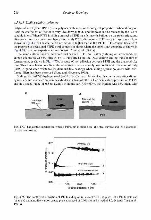
4.5.3.13 Sliding against polymers
Polytetrafluorethylene (PTFE) is a polymer with superior tribological properties. When sliding onitself the coefficient of friction is very low, down to 0.08, and the wear can be reduced by the use ofsuitable fillers. When PTFE is sliding on steel a PTFE transfer layer is built up on the steel surface andafter some time the contact mechanism is mainly PTFE sliding on a PTFE transfer layer on steel, asshown in Fig. 4.77a. The coefficient of friction is higher than in the PTFE–PTFE contact because ofthe presence of occasional PTFE–steel contacts in places where the layer is not complete as shown inFig. 4.78, based on experimental results from Yang et al. (1991a).
The same authors showed, however, that when a PTFE pin is slowly sliding on a diamond-likecarbon coating (a-C) very little PTFE is transferred onto the DLC coating and no transfer film isformed on it, as shown in Fig. 4.77b, because of low adhesion between PTFE and the diamond-likefilm. This low adhesion results at the same time in a remarkably low coefficient of friction of only0.035. A good wear resistance for diamond-like coatings when sliding against polymers with rein-forced fillers has been observed (Yang and Hirvonen, 1993).
Sliding of a PACVD hydrogenated (a-C:H) DLC coated flat steel surface in reciprocating slidingagainst a 5 mm diameter polyamide cylinder at a load of 50 N, a Hertzian surface pressure of 35 GPaand in a speed range of 0.3 to 1.2 m/s in humid air, RH¼ 60%, the friction was very high, with
Fig. 4.77. The contact mechanism when a PTFE pin is sliding on (a) a steel surface and (b) a diamond-like carbon coating.
Fig. 4.78. The coefficient of friction of PTFE sliding on (a) a steel AISI 316 plate, (b) a PTFE plate and(c) an a-C diamond-like carbon coated plate at a speed of 0.006 m/s and a load of 3.05 N (after Yang et al.,1991a).
286 Coatings Tribology
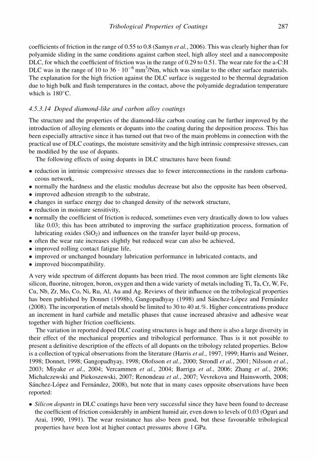
coefficients of friction in the range of 0.55 to 0.8 (Samyn et al., 2006). This was clearly higher than forpolyamide sliding in the same conditions against carbon steel, high alloy steel and a nanocompositeDLC, for which the coefficient of friction was in the range of 0.29 to 0.51. The wear rate for the a-C:HDLC was in the range of 10 to 36 $ 10�6 mm3/Nm, which was similar to the other surface materials.The explanation for the high friction against the DLC surface is suggested to be thermal degradationdue to high bulk and flash temperatures in the contact, above the polyamide degradation temperaturewhich is 180�C.
4.5.3.14 Doped diamond-like and carbon alloy coatings
The structure and the properties of the diamond-like carbon coating can be further improved by theintroduction of alloying elements or dopants into the coating during the deposition process. This hasbeen especially attractive since it has turned out that two of the main problems in connection with thepractical use of DLC coatings, the moisture sensitivity and the high intrinsic compressive stresses, canbe modified by the use of dopants.
The following effects of using dopants in DLC structures have been found:
� reduction in intrinsic compressive stresses due to fewer interconnections in the random carbona-ceous network,� normally the hardness and the elastic modulus decrease but also the opposite has been observed,� improved adhesion strength to the substrate,� changes in surface energy due to changed density of the network structure,� reduction in moisture sensitivity,� normally the coefficient of friction is reduced, sometimes even very drastically down to low values
like 0.03; this has been attributed to improving the surface graphitization process, formation oflubricating oxides (SiO2) and influences on the transfer layer build-up process,� often the wear rate increases slightly but reduced wear can also be achieved,� improved rolling contact fatigue life,� improved or unchanged boundary lubrication performance in lubricated contacts, and� improved biocompatibility.
A very wide spectrum of different dopants has been tried. The most common are light elements likesilicon, fluorine, nitrogen, boron, oxygen and then a wide variety of metals including Ti, Ta, Cr, W, Fe,Cu, Nb, Zr, Mo, Co, Ni, Ru, Al, Au and Ag. Reviews of their influence on the tribological propertieshas been published by Donnet (1998b), Gangopadhyay (1998) and Sanchez-Lopez and Fernandez(2008). The incorporation of metals should be limited to 30 to 40 at.%. Higher concentrations producean increment in hard carbide and metallic phases that cause increased abrasive and adhesive weartogether with higher friction coefficients.
The variation in reported doped DLC coating structures is huge and there is also a large diversity intheir effect of the mechanical properties and tribological performance. Thus is it not possible topresent a definitive description of the effects of all dopants on the tribology related properties. Belowis a collection of typical observations from the literature (Harris et al., 1997, 1999; Harris and Weiner,1998; Donnet, 1998; Gangopadhyay, 1998; Olofsson et al., 2000; Strondl et al., 2001; Nilsson et al.,2003; Miyake et al., 2004; Vercammen et al., 2004; Barriga et al., 2006; Zhang et al., 2006;Michalczewski and Piekoszewski, 2007; Renondeau et al., 2007; Vevrekova and Hainsworth, 2008;Sanchez-Lopez and Fernandez, 2008), but note that in many cases opposite observations have beenreported:
� Silicon dopants in DLC coatings have been very successful since they have been found to decreasethe coefficient of friction considerably in ambient humid air, even down to levels of 0.03 (Oguri andArai, 1990, 1991). The wear resistance has also been good, but these favourable tribologicalproperties have been lost at higher contact pressures above 1 GPa.
287Tribological Properties of Coatings

� Flourine dopants in DLC coatings result in lower degrees of surface energy and lower stress levels,improved adhesion to ceramic substrates and low friction and better wear performance.� Nitrogen dopants in DLC coatings result in an increase in surface energy, reduced stresses, pres-
ervation of hardness, small influence on wear resistance and friction.� Metal dopants in DLC coatings result in reduced intrinsic stresses, reduced sensitivity to humidity,
improved adhesion to steel substrate, reduced friction down to coefficients of friction of 0.04,various influences on sliding wear, improved rolling contact fatigue life and improved boundarylubricating performance. Low friction behaviour has especially been measured for Ta dopants indry sliding.
Some of the early investigations on improving DLC coatings by dopants are described below.Matthews et al. (1989) observed some improvements in the wear resistance when adding boron nitrideor tungsten to a diamond-like a-C:H carbon coating. Coatings with the added elements showed,however, a slightly higher coefficient of friction in the range of 0.1 to 0.15 as minimum valuescompared to 0.08 for pure a-C:H carbon films.
Oguri and Arai (1990 and 1991) found that considerable improvements can be achieved by alloyinga-C:H carbon coatings with silicon. They formed amorphous carbon–silicon hydrogenated coatingsby a dc glow discharge CVD method from reactant gases of CH4, SiCl4, H2 and Ar. With a hydrogencontent of 30 to 50 at.% they recorded coefficients of friction as low as 0.04 with a ball-on-disc test atspeeds of 0.2 to 3 m/s and loads up to 33 N in a dry air environment. As a comparison, the coefficientof friction with the same experimental parameters was 0.12 for amorphous carbon coatings, 0.18 fortitanium carbide and 0.8 for an uncoated steel M2 substrate when sliding against a steel surface, asshown in Fig. 4.79. Both the amorphous carbon–silicon and carbon coatings had an excellent wearresistance with wear rates down to 10�7 mm3/Nm, as shown in Fig. 4.80. No major influence of loadon friction could be observed in the load range of 10 to 50 N. A layer of silicon dioxide (SiO2) weardebris was formed on the steel surface and this possibly plays a role in producing the excellenttribological contact conditions.
Meneve et al. (1993a, b) studied systematically rf PACVD-deposited amorphous hydrogenatedsilicon carbide (a-Si1�xCx:H) films (x¼ 0.65 to 1) in dry and humid N2 conditions. They found that
Fig. 4.79. Coefficient of friction as a function of sliding distance for a steel ball sliding against steel diskscoated by PACVD Si–a-C:H, ion-plated a-C:H, PACVD TiC, and against an uncoated steel disk ata sliding speed of 0.2 m/s and a load of 6.4 N (after Oguri and Arai, 1990).
288 Coatings Tribology

adding silicon to a diamond-like a-C:H coating reduces the hardness, elastic modulus and internalstresses by values of 15 to 30%. In pin-on-disk tests with a low load of 1 N and in dry N2 environment,the 2 mm thick silicon-containing coating showed low wear of both the coating and the counterfaceand a steady-state friction coefficient below 0.1. But at higher loads in dry N2 a pure a-C:H coatingperformed better than the a-Si1�xCx:H films in all respects.
Excellent tribological performance has been reported for metal-containing a-C:H coatings (Me-C:H) deposited by rf or dc magnetron sputtering (Dimigen and Klages, 1991). The metal dopants theyused were tantalum, tungsten, titanium and niobium. The Me-C:H coatings always exhibited com-pressive intrinsic stresses increasing with the metal content and attaining values of about 0.3 and1 GPa for Nb–C:H and Ta–C:H, respectively, with metal contents of 20 to 40%. The friction whensliding against an uncoated WC ball showed a pronounced dependence on relative humidity of theambient gas, normal load and metal content. Under optimal conditions very low coefficients offriction of 0.04 for Ta–C:H and 0.02 for W–C:H coatings were observed.
The wear of the coated disc was two orders of magnitude lower than for TiN and TiAlN PVD-deposited coatings and the wear of the counterpart was drastically reduced. The favourable tri-bological properties are attributed to a combination of ceramic-like properties, such as high hardness,and polymer-like properties, such as high elasticity and low surface energy. With regard to elasticityand surface properties the Me-C:H coatings with low metal contents bear more resemblance topolymers than to metals or ceramics, as shown in Fig. 4.81.
Improved tribological performance has also been achieved by doping zirconia, tantalum, tungsten,titanium and silicon into hard amorphous carbon coatings. The low friction coefficients and wear ratesof such coatings deposited on steel and sliding against a steel ball are shown in Fig. 4.82. It wasconcluded in this case that the carbide material has no great influence on friction and wear because theupper layer of about 1 to 2 mm consisted of pure carbon.
The positive effect of tantalum and tungsten as metal dopants in hard carbon coatings on tri-bological performance is confirmed in both oscillating and pin-on-disk tests against silicon carbide byKlafke et al. (1992). They observed that the coating performed best in conditions of high humidity.
Fig. 4.80. Wear rates as a function of sliding velocity for steel discs coated by PACVD Si–a-C:H, ion-plated a-C:H, PACVD TiC, and an uncoated steel disk (data from Oguri and Arai, 1990).
289Tribological Properties of Coatings
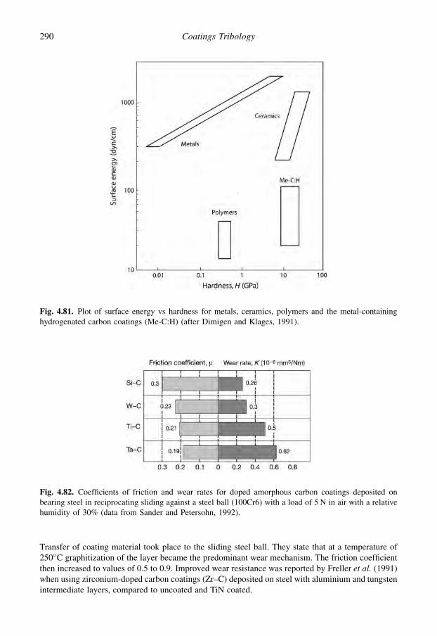
Transfer of coating material took place to the sliding steel ball. They state that at a temperature of250�C graphitization of the layer became the predominant wear mechanism. The friction coefficientthen increased to values of 0.5 to 0.9. Improved wear resistance was reported by Freller et al. (1991)when using zirconium-doped carbon coatings (Zr–C) deposited on steel with aluminium and tungstenintermediate layers, compared to uncoated and TiN coated.
Fig. 4.81. Plot of surface energy vs hardness for metals, ceramics, polymers and the metal-containinghydrogenated carbon coatings (Me-C:H) (after Dimigen and Klages, 1991).
Fig. 4.82. Coefficients of friction and wear rates for doped amorphous carbon coatings deposited onbearing steel in reciprocating sliding against a steel ball (100Cr6) with a load of 5 N in air with a relativehumidity of 30% (data from Sander and Petersohn, 1992).
290 Coatings Tribology
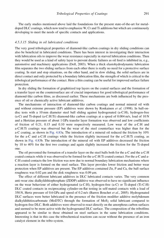
The early studies mentioned above laid the foundations for the present state-of-the-art for metal-doped DLC coatings, which now tend to emphasize W, Cr and Ti additions but which are continuouslydeveloping to meet the needs of specific contacts and applications.
4.5.3.15 Sliding in oil lubricated conditions
The very good tribological properties of diamond-like carbon coatings in dry sliding conditions canalso be beneficial in lubricated conditions. There has been interest in investigating their interactionwith lubrication oils to improve the wear resistance especially in starved lubrication conditions. Thenthey would be used as a kind of safety layer to prevent drastic failures as oil feed is inhibited in, e.g.,automotive and machinery applications (Doll, 2003). When a thick elastohydrodynamic lubricationfilm separates the two sliding surfaces from each other there is really no need for a protective surfacecoating. In start and stop situations, on the other hand, and in slow sliding, the solid surfaces are indirect contact and only protected by a boundary lubrication film, the strength of which is critical to thetribological performance of the contact. Here a thin coating can be useful for improved surface failureprotection.
In dry sliding the formation of graphitized top layers on the coated surfaces and the formation ofa transfer layer on the countersurface are of crucial importance for good tribological performance ofdiamond-like carbon films, as discussed earlier. These mechanisms are both influenced by the pres-ence of oil or chemically active lubricant additives.
The mechanisms of interaction of diamond-like carbon coatings and normal mineral oil withand without extreme pressure (EP) additives were shown by Ronkainen et al. (1998). In ball-on-disc tests with a 10 mm diameter steel ball sliding against hydrogenated (a-C:H), hydrogen-free(a-C) and Ti-doped (a-C:H:Ti) diamond-like carbon coatings at a speed of 0.004 m/s, load of 10 Nand a Hertzian pressure of about 1 GPa transfer layer formation was observed and low coefficientsof friction of 0.21, 0.15 and 0.10 were respectively measured. Low wear of the a-C:H anda-C:H:Ti coatings was observed but the wear of the steel counterface was higher than for thea-C coating, as shown in Fig. 4.83a. The introduction of a mineral oil reduced the friction by 10%for the a-C and a-C:H coatings while the friction slightly increased for the a-C:H:Ti coating, asshown in Fig. 4.83b. The introduction of the mineral oil with EP additives decreased the frictionby 10 to 40% for the first two coatings and again slightly increased the friction for the Ti-dopedone.
The oil prevented the formation of a transfer layer on the steel balls both for the a-C and the a-C:Hcoated contacts while it was observed to be formed for the a-C:H:Ti coated contact. For the a-C and a-C:H coated contacts the low friction was now due to normal boundary lubrication mechanisms wherea reaction layer is formed on the steel surface. This layer provides lower friction and better wearprotection when EP additives are present. The EP additives contained Zn, P and Ca, the ball surfaceroughness was 0.02 mm and the disk roughness was 0.09 mm.
The effect of different lubricant additives in DLC lubricated contacts varies. The very commonanti-wear zinc dialkyldithiophosphate (ZDDP) additive was observed to have no significant influenceon the wear behaviour of either hydrogenated (a-C:H), hydrogen-free (a-C) or Ti-doped (Ti-C:H)DLC coated contacts in reciprocating cylinder-on-flat testing in self-mated contacts with a load of350 N, Hertz pressure of 0.6 GPa and speed of 0.2 m/s (Barros Bouchet et al., 2005). HydrogenatedDLC surfaces were better lubricated in the presence of the friction modifier additive molybdenumdialkyldithitiocarbomate (MoDTC) through the formation of MoS2 solid lubricant compared tohydrogen-free DLC. Both additives were observed to react directly on the amorphous carbon surfacesand seemed to be more active with the hydrogenated DLC surface. The composition of the tribofilmsappeared to be similar to those obtained on steel surfaces in the same lubrication conditions.Interesting is that in this case the tribochemical reactions can occur without the presence of an ironcatalyst element in the tribo-system.
291Tribological Properties of Coatings

The boundary lubrication properties of diamond-like carbon coatings can be further improved bythe use of metal dopants in the coating. This has been reported for W, Ti, Mo and Fe dopants (Miyakeet al., 2004; Podgornik and Vi�zintin, 2005; Podgornik et al., 2003, 2006a, 2008; Kalin and Vi�zintin,2006a; Podgornik, 2008).
The influence of the oil lubricant polyalphaolefin (PAO) including a commercial sulphur-based EPadditive and a ZDDP-based anti-wear (AW) additive in boundary-lubricated and starved conditionswith three W alloyed DLC coated surfaces sliding in a cross cylinder test with a 0.1 m/s speed over theload range of 150 to 1500 N was studied by Jacobson and Hogmark (2001). The endurance life wasconsiderably improved by the DLC coatings compared to uncoated surfaces, as shown in Fig. 4.84.
Fig. 4.83. Wear rates (a) and coefficients of friction (b) for uncoated, a-C, a-C:H and a-C:H:Ti coateddiamond-like carbon surfaces sliding against steel balls at 10 N load and 0.004 m/s speed in dry, mineralbase oil and EP additive containing base oil conditions (data from Ronkainen et al., 1998).
292 Coatings Tribology
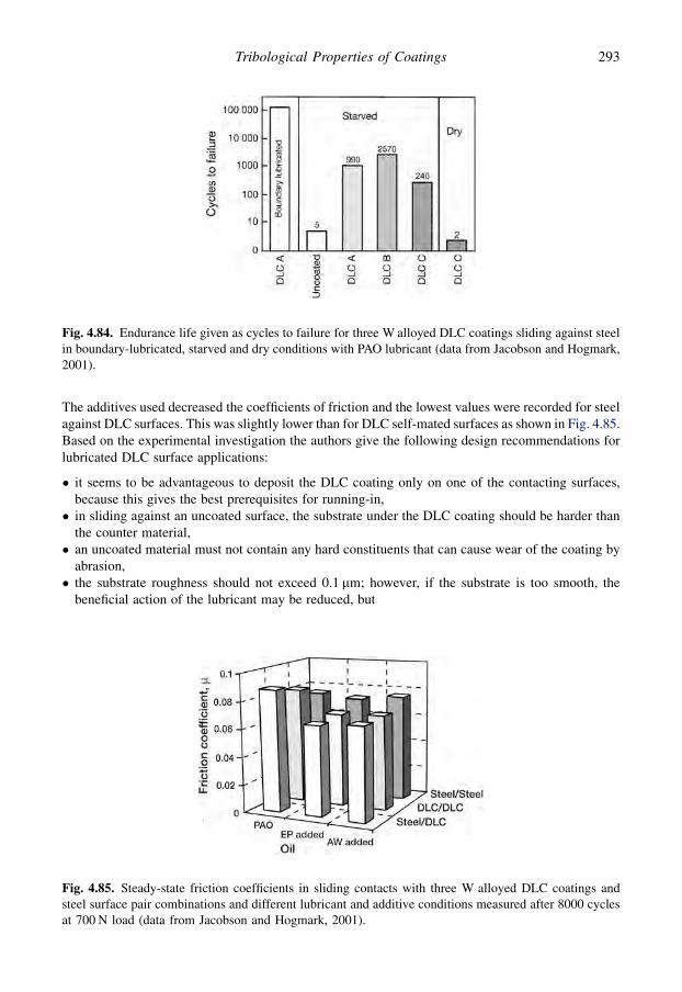
The additives used decreased the coefficients of friction and the lowest values were recorded for steelagainst DLC surfaces. This was slightly lower than for DLC self-mated surfaces as shown in Fig. 4.85.Based on the experimental investigation the authors give the following design recommendations forlubricated DLC surface applications:
� it seems to be advantageous to deposit the DLC coating only on one of the contacting surfaces,because this gives the best prerequisites for running-in,� in sliding against an uncoated surface, the substrate under the DLC coating should be harder than
the counter material,� an uncoated material must not contain any hard constituents that can cause wear of the coating by
abrasion,� the substrate roughness should not exceed 0.1 mm; however, if the substrate is too smooth, the
beneficial action of the lubricant may be reduced, but
Fig. 4.84. Endurance life given as cycles to failure for three W alloyed DLC coatings sliding against steelin boundary-lubricated, starved and dry conditions with PAO lubricant (data from Jacobson and Hogmark,2001).
Fig. 4.85. Steady-state friction coefficients in sliding contacts with three W alloyed DLC coatings andsteel surface pair combinations and different lubricant and additive conditions measured after 8000 cyclesat 700 N load (data from Jacobson and Hogmark, 2001).
293Tribological Properties of Coatings

� for a contact with both surfaces coated by DLC the recommendation is less straightforward: plasticdeformation of the substrate and associated coating failure may occur if the substrates are too soft;soft substrates accordingly require deformable coatings; but on the other hand a too hard substratemight reduce the ability for running-in.
The lubrication, friction and wear mechanisms related to lubricated DLC contacts with variouscounterface materials and various lubricants and lubricant additives has been reported by Podgorniket al. (2003, 2008), Podgornik and Vi�zintin, (2005), Kalin and Vi�zintin (2006a, b), Kano (2006),Equey et al. (2007, 2008), Neville et al. (2007), Andersson et al. (2008), Barros’Bouchet and Martin(2008), Manier et al. (2008) and Podgornik (2008). A general conclusion is that DLC coatings can beused in most lubricated contacts, they provide an additional protective layer; depositing only onto oneof the mating surfaces shortens the running-in of the surfaces and may be beneficial for boundarylubrication layer formation. When alloyed with suitable dopants they can interact beneficially withlubricant additives and provide excellent tribological conditions. It is obvious that the tribologicalperformance deeply depends on the nature of the DLC material, the additive composition and thecontact conditions.
4.5.3.16 Abrasive wear resistance
The diamond-like carbon coatings are most known for their extraordinarily low sliding frictionproperties and for this reason most of the investigations are also focused on behaviour in slidingconditions. However, their abrasive wear resistance seems to be similar to that of other hard coatingsbased on the few investigations carried out.
With the ball crater test method using hard TiO2 particles to cause the abrasive wear Van Acker andVercammen (2004) compared the wear resistance of three PACVD DLC coatings and six other hardcoatings. The DLC coatings were about 2 mm thick, the surface roughness was 0.008 mm, the hardnessin the range of 11 to 24 GPa and the Young’s modulus in the range of 107 to 162 GPa. The hard DLCcoating had the best wear resistance of all the coatings while the soft DLC coating had the poorestwear resistance, as shown in Fig. 4.86. In the comparison of all the tested coatings there was nohardness vs wear resistance correlation. However, for the three DLC coatings the abrasive wearresistance correlated directly with the hardness of the coatings. Good abrasive wear resistance ofmetal-doped DLC coatings has been reported by Harris et al. (1997).
4.5.3.17 Rolling contact fatigue wear resistance
In contrast to sliding tests, diamond-like carbon coatings did not perform well in early rolling contactfatigue testing and often failed earlier than uncoated samples or showed no improvement (Rosadoet al., 1997). However, recent slip-rolling tests in lubricated conditions with Hertzian surface pres-sures in the range of 1 to 1.5 GPa carried out by Klaffke et al. (2005b) and Lohr et al. (2006) showpromising results. They tested 40 roller samples coated by seven different DLC coatings including a-C:H, a-C:H:W, a-C:H:Ta/TiþW, a-C:H, a-C:H:Si and ta-C. The variation between the differentcoatings, but also between samples coming from the same deposition batch, varied significantly, evenmore than three orders of magnitude in number of revolutions to failure, e.g. from 300 to one millionrevolutions. This shows first of all that the quality of the coated surfaces is not at all on the level ofwhat is required for components used in highly loaded rolling fatigue contacts.
In sliding the contact process is less severe and more forgiving but in rolling contact fatigue evenone small defect close to the surface may immediately have a fatal consequence. However, thepromising part of the tests was that there were two DLC coated rollers, the hard a-C:H and ta-Ccoated, that showed very good rolling fatigue life and rolled without failure up to 107 revolutions,which is a good result. When in the future similar coated components of good homogeneity and
294 Coatings Tribology
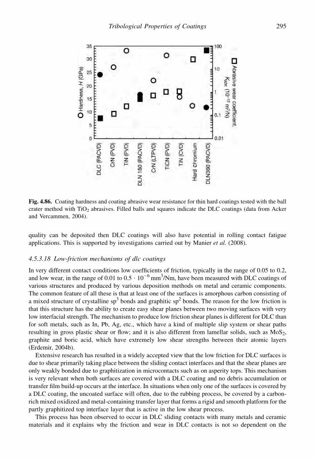
quality can be deposited then DLC coatings will also have potential in rolling contact fatigueapplications. This is supported by investigations carried out by Manier et al. (2008).
4.5.3.18 Low-friction mechanisms of dlc coatings
In very different contact conditions low coefficients of friction, typically in the range of 0.05 to 0.2,and low wear, in the range of 0.01 to 0.5 $ 10�6 mm3/Nm, have been measured with DLC coatings ofvarious structures and produced by various deposition methods on metal and ceramic components.The common feature of all these is that at least one of the surfaces is amorphous carbon consisting ofa mixed structure of crystalline sp3 bonds and graphitic sp2 bonds. The reason for the low friction isthat this structure has the ability to create easy shear planes between two moving surfaces with verylow interfacial strength. The mechanism to produce low friction shear planes is different for DLC thanfor soft metals, such as In, Pb, Ag, etc., which have a kind of multiple slip system or shear pathsresulting in gross plastic shear or flow; and it is also different from lamellar solids, such as MoS2,graphite and boric acid, which have extremely low shear strengths between their atomic layers(Erdemir, 2004b).
Extensive research has resulted in a widely accepted view that the low friction for DLC surfaces isdue to shear primarily taking place between the sliding contact interfaces and that the shear planes areonly weakly bonded due to graphitization in microcontacts such as on asperity tops. This mechanismis very relevant when both surfaces are covered with a DLC coating and no debris accumulation ortransfer film build-up occurs at the interface. In situations when only one of the surfaces is covered bya DLC coating, the uncoated surface will often, due to the rubbing process, be covered by a carbon-rich mixed oxidized and metal-containing transfer layer that forms a rigid and smooth platform for thepartly graphitized top interface layer that is active in the low shear process.
This process has been observed to occur in DLC sliding contacts with many metals and ceramicmaterials and it explains why the friction and wear in DLC contacts is not so dependent on the
Fig. 4.86. Coating hardness and coating abrasive wear resistance for thin hard coatings tested with the ballcrater method with TiO2 abrasives. Filled balls and squares indicate the DLC coatings (data from Ackerand Vercammen, 2004).
295Tribological Properties of Coatings

counterface material as is normally the case in tribological contacts. Here the counterface material hasthe role of only being a platform for the formed transfer layer. The main parameters that influence thiscontact mechanism and thus the friction and wear performance are the hydrogen content of thecoating, the surface roughness of the surfaces, mechanical strength (hardness and elasticity) of thesurfaces, normal load and speed of the contacting surfaces and the environment, as discussed above.
4.5.3.19 Superlubricity of DLC coatings
In dry nitrogen extremely low friction of specially prepared DLC surfaces has been measured, witha coefficient of friction in the range of 0.001 to 0.005 and even below 0.001, which representssuperlubricity and is shown in Fig. 4.87 (Erdemir et al., 2000, 2001). The wear rate was also low, in therange of 0.00001 to 0.001 $ 10�6 mm3/Nm. These DLC hydrogen-rich coatings, called nearly fric-tionless carbon (NFC), were developed and tested by Erdemir and his co-workers and their superlowfriction mechanism has been extensively investigated and described (Erdemir et al., 2000, 2001, 2008;Dickrell et al., 2004; Erdemir, 2004a, b; Erdemir and Eryilmaz, 2007; Fontaine and Donnet, 2007).
To reach the conditions of superlubricity, first macro- and microscale friction increasing effectsmust be eliminated. Ploughing friction can be avoided by using hard substrates, and asperity collisionscan be avoided by using atomically smooth surfaces, such as Si wafers, sapphire or cleaved mica. Theloads and speeds are low and the inert environment excludes humidity and contamination effects. Nowwhen disturbing friction increasing effects are eliminated the next challenge is to create the conditionsfor extremely weakly bonded shear planes. The mechanism for this in the NFC coatings is believed tobe the dangling bond orbital mechanisms presented earlier in section 4.5.2 and shown in Fig. 4.49.
The shear is taking place between two atomically smooth planes of hydrogen atoms bonded per-pendicularly from the shear plane to the free dangling bond orbitals of carbon in the DLC coating. Thecoatings are highly hydrogenated to provide enough hydrogen for all free dangling bonds to avoid thepossibility that some strong covalent bonds are formed between the surfaces. Some unbonded freehydrogen can serve as a reservoir and replenish or replace those hydrogen atoms that may have beenlost due to thermal heating and mechanical grinding during sliding. A molecular dynamic simulationof an NFC coating structure including bonded, atomic and molecular hydrogen within the coating is
Fig. 4.87. Superlubricity coefficients of friction of highly hydrogenated DLC coatings deposited ona smooth steel surface (Ra¼ 20 nm) and on a very smooth sapphire surface (Ra¼ 0.7 nm) sliding self-mated in dry nitrogen with a load of 10 N and a speed of 0.03 m/s (data from Erdemir, 2004b).
296 Coatings Tribology

shown in Fig. 4.88. The effect of the hydrogen-to-carbon ratio on friction and wear is shown inFig. 4.69 and the paramount role of hydrogen in superlow friction has been confirmed by Fontaineet al. (2004).
Erdemir (2004b) proposes as the genesis of superlow friction a mechanistic model of superlubricityof DLC coatings. In addition to the above, he presents that in the highly hydrogenated gas dischargeplasmas some carbon atoms can be di-hydrogenated during deposition and the existence of di-hydrogenated carbon atoms on the surface will further increase the hydrogen density of the surfacesand thus provide better shielding or passivation of the surfaces. One more reason for these DLCsurfaces to provide extremely low friction is that, when the free electrons of hydrogen atoms pair withthe dangling s-bonds of surface carbon atoms, the electrical charge density is permanently shifted tothe other side of the nucleus of the hydrogen atom and away from the surface. This allows thepositively charged hydrogen proton to be closer to the surface than the electron. A dipole configu-ration is created at the sliding interface and it gives rise to repulsion rather than to attraction betweenthe hydrogen-terminated sliding surfaces of the DLC coatings. The two atomically smooth surfacesare in a way flying over each other on repulsive forces without any material-internal shear (Su and Lin,1998; Dag and Ciraci, 2004; Erdemir and Donnet, 2006).
4.5.3.20 Scales of DLC coating tribological mechanisms
Diamond-like carbon surfaces have been found to have excellent tribological properties in manydifferent sliding situations and they are today already in wide commercial use. Their connection tonatural diamond surfaces and also the possibility to achieve the lowest coefficient of friction measured
Fig. 4.88. Tight-binding molecular dynamic simulation of highly hydrogenated DLC coatings, showingbonded, atomic and molecular hydrogen within the structure (from Erdemir, 2004b, with permission).
297Tribological Properties of Coatings
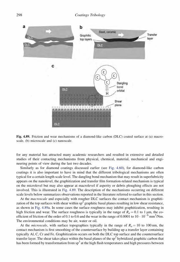
for any material has attracted many academic researchers and resulted in extensive and detailedstudies of their contacting mechanisms from physical, chemical, material, mechanical and engi-neering points of view during the last two decades.
Similarly as for diamond coatings discussed earlier (see Fig. 4.60), for diamond-like carboncoatings it is also important to have in mind that the different tribological mechanisms are oftentypical for a certain length scale level. The dangling bond mechanism that may result in superlubricityappears on the nanolevel, the graphitization and transfer film formation-related mechanism is typicalon the microlevel but may also appear at macrolevel if asperity or debris ploughing effects are notinvolved. This is illustrated in Fig. 4.89. The description of the mechanisms occurring on differentscale levels below summarizes observations reported in the literature referred to earlier in this section.
At the macroscale and especially with rougher DLC surfaces the contact mechanism is graphiti-zation of the top surfaces with shear within sp2 graphitic basal planes resulting in low shear resistance,as shown in Fig. 4.89a. In some cases the surface roughness may inhibit graphitization, resulting inhigh friction and wear. The surface roughness is typically in the range of Ra¼ 0.1 to 1 mm, the co-efficient of friction of the order of 0.1 to 0.6 and the wear in the range of 0.0001 to 10 $ 10�6 mm3/Nm.The environmental conditions may be air, water or oil.
At the microscale, with surface topographies typically in the range of Ra¼ 10 to 100 nm, thecontact mechanism is first smoothing of the countersurface by building up a transfer layer containingtypically Al, C, Cr and Fe. Graphitization occurs on both the DLC top surface and the countersurfacetransfer layer. The shear takes place within the basal planes of the sp2 hybridized graphitic carbon thathas been formed by transformation from sp3 at the high flash temperatures and high pressures between
Fig. 4.89. Friction and wear mechanisms of a diamond-like carbon (DLC) coated surface at (a) macro-scale, (b) microscale and (c) nanoscale.
298 Coatings Tribology
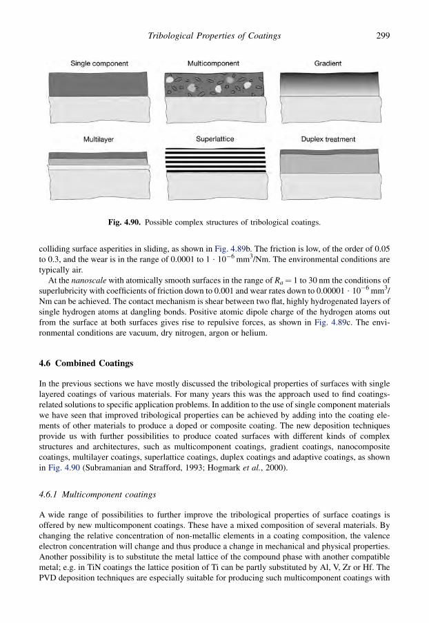
colliding surface asperities in sliding, as shown in Fig. 4.89b. The friction is low, of the order of 0.05to 0.3, and the wear is in the range of 0.0001 to 1 $ 10�6 mm3/Nm. The environmental conditions aretypically air.
At the nanoscale with atomically smooth surfaces in the range of Ra¼ 1 to 30 nm the conditions ofsuperlubricity with coefficients of friction down to 0.001 and wear rates down to 0.00001 $ 10�6 mm3/Nm can be achieved. The contact mechanism is shear between two flat, highly hydrogenated layers ofsingle hydrogen atoms at dangling bonds. Positive atomic dipole charge of the hydrogen atoms outfrom the surface at both surfaces gives rise to repulsive forces, as shown in Fig. 4.89c. The envi-ronmental conditions are vacuum, dry nitrogen, argon or helium.
4.6 Combined Coatings
In the previous sections we have mostly discussed the tribological properties of surfaces with singlelayered coatings of various materials. For many years this was the approach used to find coatings-related solutions to specific application problems. In addition to the use of single component materialswe have seen that improved tribological properties can be achieved by adding into the coating ele-ments of other materials to produce a doped or composite coating. The new deposition techniquesprovide us with further possibilities to produce coated surfaces with different kinds of complexstructures and architectures, such as multicomponent coatings, gradient coatings, nanocompositecoatings, multilayer coatings, superlattice coatings, duplex coatings and adaptive coatings, as shownin Fig. 4.90 (Subramanian and Strafford, 1993; Hogmark et al., 2000).
4.6.1 Multicomponent coatings
A wide range of possibilities to further improve the tribological properties of surface coatings isoffered by new multicomponent coatings. These have a mixed composition of several materials. Bychanging the relative concentration of non-metallic elements in a coating composition, the valenceelectron concentration will change and thus produce a change in mechanical and physical properties.Another possibility is to substitute the metal lattice of the compound phase with another compatiblemetal; e.g. in TiN coatings the lattice position of Ti can be partly substituted by Al, V, Zr or Hf. ThePVD deposition techniques are especially suitable for producing such multicomponent coatings with
Fig. 4.90. Possible complex structures of tribological coatings.
299Tribological Properties of Coatings

a large variety of different compositions (Freller and Haessler, 1988; Holleck, 1991; Knotek et al.,1992c; Subramanian and Strafford, 1993; Hogmark et al., 2000).
Superhard multicomponent coatings with improved abrasive wear resistance were developed byKnotek et al. (1990b). By magnetron sputter ion plating they incorporated carbon and nitrogen atomsin the titanium–boron structure, as shown in Fig. 4.91a, and produced Ti–B–N, Ti–B–C and Ti–B–C–N coatings. The thickness of the coatings was in the range of 6 to 25 mm on cemented carbide, high-speed steel and austenitic stainless steel substrates. Considerably improved wear resistance was ob-served for Ti–B–C coatings in abrasive wear tests, as shown in Fig. 4.91b. The volumetric wear rate ofthe different coatings was in direct relation to the microhardness of the coatings.
A multicomponent composition of Ti–Al–V–N–C was optimized for wear protection of carbideindexable inserts used for turning (Knotek et al., 1988). The choice of deposition target compositionsand configurations of the complex coatings are shown in Fig. 4.92 and the results of tool life de-termined by crater depth in turning tests are shown in Fig. 4.93. It can be seen that a specific com-position of (Ti,Al,V)C,N resulted in significantly improved tool life. The optimized coating possessesgood hardness, good adhesion and adequate thermal stability, even after lengthy high temperatureannealing. The results are supported by good wear behaviour in tool life turning tests in terms of bothcrater and flank wear.
It is now realized that the early promise of multicomponent coatings of the kinds referred to abovewas usually due to the influence of small grain sizes on mechanical, physical and chemical properties.This realization has resulted in an increase in research into nanocomposite multicomponent coatings.
4.6.1.1 Gradient coatings
Gradient coatings are a type of multicomponent coating in which the compositions or structuralmorphologies continuously change when moving from the substrate to the surface. This gives the
Fig. 4.91. (a) Possible incorporation sites of the metalloid atoms carbon and nitrogen in the hexagonalTiB2 cell. (b) Wear volume as a function of time for multicomponent and reference coatings from abrasivewear tests. The microhardness (Hv 0.05) of the surface is given in the figure. The abrasive medium was anAl2O3 suspension and counterpart 100Cr6 (data from Knotek et al., 1990b).
300 Coatings Tribology

possibility to vary the properties of the coating at different depths from the surface. WC–TiC–TiNgradient coatings, where the composition changes from WC over TiC to TiN, were deposited bymagnetron sputtering on hard metal substrates and tested in turning conditions by Fella et al. (1988).Figure 4.94 shows the PVD phase diagram and the change in composition of the gradient coatings inthe WC–TiC–TiN system. For comparison, similar coatings with a reversed order of compositionwere produced. Results from turning tests of steel (AISI 1042) in Fig. 4.95 show that flank and craterwear are reduced to a level almost as low as for TiN or TiC coated tools.
Fischer and Oettel (1997) have discussed how microstructural gradients can be achieved in TiNcoatings by time-dependent variations in the bias voltage during deposition, and this can beneficially
Fig. 4.92. Deposition target composition and configurations in the complex multicomponent (Ti,Al,V)Nand (Ti,Al,V)C,N coatings (after Knotek et al., 1988).
Fig. 4.93. Tool life determined by crater wear depth of multicomponent (Ti,Al,V)N and (Ti,Al,V)C,Ncoatings on carbide indexable inserts in turning tests (data from Knotek et al., 1988).
301Tribological Properties of Coatings

modify the stress state and the adhesion. It is, however, more common to utilize compositionalgradients to achieve such benefits. For example, commercial TiCN coatings are provided with aninitially deposited layer of TiN to promote adhesion to the substrate and then the nitrogen content ofthe process gas is gradually increased to make TiCN with a graded composition running from pureTiN to TiCN over a few 100 nm of coating growth. This graded layer may or may not be overcoatedwith a layer of TiCN with fixed composition. The hardness, adhesion and the tribological behaviour ofsuch coatings have been studied (Bull et al., 2003a, b), and their findings suggest that by using
Fig. 4.94. PVD phase diagram at 500 K showing the change in composition of the multicomponentgradient WC–TiC–TiN coating when moving from substrate to surface. a is the coefficient of thermalexpansion in 10�6 K�1 (after Fella et al., 1988).
Fig. 4.95. Flank and crater wear after turning of steel with multicomponent gradient coated tools andreference coated tools (data from Fella et al., 1988).
302 Coatings Tribology

predictive hardness modelling, coating architectures can be designed to give improved hardnessresponses.
Uglov et al. (2005, 2008) have deposited gradient Ti–Cr–N coatings and have shown that these canhave reduced internal stress compared with coatings of constant through-thickness composition. Theyfound that the mechanical properties, hardness and elastic modulus of the gradient coatings are thesuperposition of the solid solutions TixCr1�x N of different concentrations (0.6< x< 0.84 and0.25< x< 0.67). Many researchers have found that ternary coatings are harder than either of theparent binary nitrides. Boxman et al. (2000) reported this for (TiZr)N, (Ti, Nb)N and (Zr, Nb)N, whichexplains why compositional variations can be used affectively to control not only chemical andstructural characteristics but also mechanical properties. Indeed, gradient coatings have proved to beparticularly effective in enhancing thermal barrier coating (TBC) performance (Movchan andMarinski, 1998; Movchan, 2002). In that case a gradient composition through an NiAl bond coat at thecoating/substrate interface, through to a yttria-stabilized zirconia (YSZ) at the outer surface providesthe desired adhesion and the capability to accommodate strain caused by differential thermal ex-pansion between the coating and substrate, as well as the required thermal, tribological and hot-corrosion barrier properties. As well as YSZ, other functionally gradient TBC coatings are beinginvestigated, including NiCrAlþMgZrO3 (Tekmen et al., 2003). Malzbender (2004) has modelledthe effects of mechanical and thermal stresses on TBCs, to aid in predicting mechanical behaviour andlifetimes of coatings.
Many examples of compositionally gradient coatings can be found in the coatings literature. Mostof these relate to coatings for cutting tools, with particular emphasis on the Ti–Al–N system and itsderivatives (Qiao et al., 2000; Manaila et al., 2002; Zhou et al., 2004). Other gradient systemsreported include several which include carbon, such as Ti–TiN/CNx (Donnet et al., 1999; Stuber et al.,1999; Fernandez-Ramos et al., 2004).
4.6.2 Nanocomposite coatings
Several of the gradient coatings mentioned above have nanocomposite structures. Nanocompositecoatings are coatings with structural features, like the grain size, with dimensions below 100 nm. Suchcoatings can be achieved by controlling deposition parameters when mutually insoluble phases aresimultaneously deposited or by subsequent heat treatment. The yield strength, hardness and toughnessof polycrystalline materials all generally improve with decreasing grain size. A similar phenomenonseems to be valid for thin coatings down to nanometre size grains. In addition to mechanical prop-erties, nanocrystalline materials can exhibit higher thermal expansion, lower thermal conductivity,and unique optical, magnetic and electronic properties. Nanocomposite hard coatings may be formedby a nitride-forming transition metal and a metal component or another compound which is notdissolved in the nitride. In a second class of nanocomposite coatings the nitride crystallites are em-bedded in an amorphous phase of another compound (Hogmark et al., 2000; Zhang et al., 2005b;Galvan, 2007; Jehn, 2006).
Because of its excellent properties, nc-TiN/a-Si3N4 is a widely studied hard coating system. It iscomposed of the nanocrystalline nitride and amorphous silicon nitride, where the nc-crystallites areembedded in the amorphous Si3N4 phase. Additionally, a third phase is formed, a- and nc-TiSi2, whichforms smaller crystallites in the amorphous boundary phase. Examples of other nanocomposite hardcoating systems are: Ti–Ag–N, Ti–Cu–N, Ti–Ni–N, Zr–Ni–N, Cr–Cu–N, Mo–Cu–N, Mo2N/Ag, nc-ZrN/a–Si3N4, Ti–Al–V–Si–N, nc-(Al1�xTix)N/a-Si3N4 and h-BN/c-BN (Jehn, 2006).
The detailed friction and wear mechanism of nanocomposite coatings in tribological contacts isquite complex and merits extensive investigation. There are interesting tribological studies ofnanocomposite coatings that demonstrate the potential of these films, such as the investigation of WC/DLC/WS2 nanocomposite coatings (Voevodin et al., 1999a), nanocrystalline yttria-stabilized zirconia(YSZ) imbedded in an amorphous YSZ/metal matrix (Muratore et al., 2006), TiC/a-C:H
303Tribological Properties of Coatings

nanocomposite coatings (Pei et al., 2006), TiC/DLC nanocomposite coatings (Galvan, 2007),nanostructured tungsten carbide particles/polymer composite coatings (Wang and Lim, 2007), toughnanocrystalline carbide/amorphous DLC coatings (Voevodin, 2008) and Cu-doped TiN, CrN andMoN nanocomposite coatings (Ozt}urk et al., 2008).
A combination of a nanocrystalline/amorphous DLC design with a functionally graded interfacecan provide high cohesive toughness and high interface adhesive toughness, as shown in Fig. 4.96.
Interesting new tribological features were reported by Pei et al. (2006) in their study of TiC/a-C:Hnanocomposite coatings. They report self-lubricating effects resulting in ultra-low friction andsuperior wear resistance, transfer film formation on the counterpart and a breakdown of the Coulombfriction law in the nanocomposite coating contact mechanism. In addition, they recorded that thecoefficient of friction decreased with decreasing relative humidity. The tests were carried out witha pin-on-disk device, the counterpart was a 100Cr6 steel ball with 6 mm diameter, normal load was5 N and sliding speed in the range of 0.1 to 0.5 m/s in room temperature and this resulted in frictioncoefficients of 0.013 to 0.047 and a wear rate of 0.01 $ 10�6 mm/Nm.
Nanocomposite coatings are mentioned frequently elsewhere in this book, such as the metallic andceramic materials-related aspects of nanocomposites discussed in section 2.6.2, and the variouscarbon-based coatings containing nanocrystals discussed in section 4.5. A book edited by Cavaleiroand De Hosson (2006) provides a particularly useful insight into the current research state-of-the-artof this topic, and the paper by Veprek and Veprek-Heijman (2008) provides a review of industrialapplications of superhard nanocomposite coatings.
4.6.3 Multilayer coatings
Many of the gradient layer coatings mentioned above, and even some coatings classified as nano-composites, are in fact multilayers. This may arise due to the nature of the deposition process,involving, for example, planetary rotation of components past a series of vapour sources. One of theearliest exponents of the benefits of multilayering of PVD coatings for tribological applications wasHolleck (Holleck, 1986, 1991; Holleck et al., 1990; Holleck and Schier, 1995) who particularly
Fig. 4.96. Schematic of a tough nanocomposite coating, featuring a nanocrystalline/amorphous design inthe main coating layer for cohesive toughness and a functionally gradient interface layer for adhesivetoughness. DLC is used as an amorphous phase in this design together with nanocrystalline carbide phases(after Voevodin, 2008).
304 Coatings Tribology

emphasized the use of a large number of repeated layers. There are three main reasons why it may beadvantageous to use layered coatings.
1. Interface layers. These are increasingly used to improve the adhesion of a coating to the substrateand to ensure a smooth transition from coating properties to substrate properties at the coating/substrate boundary. Additional effects may be to inhibit the substrate material from influencing thecoating deposition process, to add a substrate wear-protecting layer or to decrease the probabilityof pinholes in the coating system.
2. Large number of repeated layers. By depositing several thin layers with various mechanicalproperties on each other the stress concentration in the surface region and the conditions for crackpropagation can be improved.
3. Diverse property layers. The properties of the surface can be improved by depositing layers ofcoatings that separately have different kinds of effects on the surface, such as corrosion protection,wear protection, thermal isolation, electrical conductivity, diffusion barrier and adhesion to thesubstrate.
The plasma-assisted PVD process is most suitable for the production of both multilayer and multi-component coatings because of its high flexibility in terms of materials which can be deposited. Withthis process surface layers can be formed from any desired metal or metal-based component, and thecoating can be deposited on virtually any substrate material (Matthews, 1988a; Holleck, 1991; Knoteket al., 1992c; Subramanian and Strafford, 1993; Hogmark et al., 2000; Jehn, 2000, 2006).
4.6.3.1 Interface layers
In tribological applications of surface coatings, very commonly the adhesion of the coating to thesubstrate is one of the crucial problems to overcome before a satisfactory surface behaviour can beachieved. One technique that may be helpful, and which is increasingly being used, is to deposit a verythin interface layer on the substrate before the coating is deposited. By a correct material choice suchan interface can replace weak coating-to-substrate bonds with a strong coating-to-interface layer andinterface layer-to-substrate bond. Another effect of the interface layer can be to reduce the internalstresses in the interface region. By the use of at least two layers on each other the probability ofpinholes or defects going from the surface to the substrate is decreased as shown in Fig. 7.41 (Knoteket al., 1992e).
Thin pure titanium interface layers have successfully been used by Valli et al. (1985a); Chenget al. (1989); Peebles and Pope (1989); Matthes et al. (1990b) and Kim et al. (2003) to improvethe wear resistance of TiN coatings on steel substrates in different wear situations. The charac-teristics of different reported coatings and interface layers are given in Table 4.2. Cheng et al. (1989)show that the interface layer increases the attachment of the TiN coating to the substrate via a betterinterface contact and stronger chemical bonds. Matthes et al. (1990b), on the other hand, showthat the wear resistance improvement in their experiments originates from improved coating qualitydue to a reduced influence from graphite in the grey cast iron substrate on the growth of the hardcoating.
A thin chromium layer has been used by Farges et al. (1989) to improve the adhesion of a layeredtungsten–carbon/tungsten carbide coating to a steel substrate. Chromium also proved to be a suitableinterface layer for improved erosion resistance when depositing hard coatings such as ZrB2 onpolyimide substrates (Chambers et al., 1990). The use of titanium interface layers under TiC/Nicoatings on polyimide was not, however, successful.
The effect of ambient, thermal and mechanical stresses on the adhesion of a titanium layer toa polyimide substrate in different multilayer systems has been analysed by Seshan et al. (1989). Withpull tests they showed that the titanium–polyimide bonding degrades by a thermochemical mecha-nism when the composite is thermally cycled. Through finite element techniques they demonstrate
305Tribological Properties of Coatings

Table 4.2. Examples of interface layers for coating-to-substrate adhesion improvement.
No. Substrate Interface layer Coating Testing device Reference
Material Thickness nm Material Thickness mm Deposition method
1 Steel (AISIM50) Ti 150 TiN 2 Ion-plating Scratch tester Cheng et al. (1989)2 Steel (304SS) Ti 16 TiN 0.1 Reactive
evaporationPin-on-plate weartester
Peebles and Pope(1989)
3 Grey cast iron Ti 1000 TiN 5–7 Rf sputtering Sheet metalforming tester
Matthes et al.(1990b)
4 Tool steel Cr 4 W–C 16 Reactive sputtering Pin-on-disk tester Farges et al. (1989)5 Polyimide Cr 12 ZrB2 20–30 Sputtering Erosion tester Chambers et al.
(1990)6 Cemented carbide TiC, TiN or Ti
(C, N)20–40 Al2O3 1–3 CVD and PVD Scratch tester Lhermitte-Sebire
et al. (1986)7 Silicon, iron,
cemented carbideSi3N4 C–BN 1.5 Reactive
evaporationRing-on-disk tester Inagawa et al.
(1989)8 Steel Cu 50–100 Pb 100 Rf sputtering Ball-on-disk tester Gerkema (1985)
9 Cemented carbide TiC 5000 Al2O3 1–2 CVD Scratch tester Hintermann andLaeng (1982)
10 Ceramic (ZrO2) SiC 10–20 DLC 2 Ion beamdeposition
Ball-on-disk Erdemir et al.(1991c)
11 Steel Zr:C, W, Ta, CrN,Al
100–4400 DLC PVD-PCVD Scratch tester Freller et al. (1991)
12 Steel TiC 1000 DLC 2 Rf CVD Scratch tester Yoshino et al.(1991)
13 Ceramic (MgO–PSZ)
Ti 25 Ag 1.5 IBAD Pin-on-disk Erdemir et al.(1991b)
14 Ceramic (A2O3) Ti 25 Ag 1.5 Sputtering Pin-on-disk DellaCorte et al.(1992)
15 Steel (440C) Au–Pb 1.5–4.5 MoS2 10 Rf magnetronsputtering
Two-disk rollingtest
Hopple et al. (1993)
16 WC–Co TiC 1.5 Al2O3 10 CVD Scratch tester Echigoya et al.(1994)
17 Steel Si3N4 DLC 20 Diamond 30–80 Microwave PACVD Topple tester Itoh et al. (1999)18 AISI H13 Ti 0.24 TiN 0.24–0.75 Arc ion-plating Impact Kim et al. (2003)19 WC–Co Cu and Cu/Ti Diffused Diamond 10 Microwave PACVD Scratch tester Huang et al. (2007)
30
6C
oa
ting
sT
ribo
log
y

that when loads and displacements are imposed at the coating-to-substrate interface, large localizedstresses are developed.
Possibilities of improving the adhesion of alumina coatings on cemented carbide substrates byusing 20 to 40 mm thick PVD or CVD intermediate TiN, TiC or Ti(C,N) layers were studiedby Lhermitte-Sebire et al. (1986). They found that when alumina is deposited at low temperatures, e.g.by PVD methods such as ion beam sputtering, the adhesion remains poor and failure of the bondoccurs, owing to insufficient chemical interdiffusion. In contrast, when interdiffusion takes place, i.e.for alumina deposited by CVD at high temperatures, the strength of the adhesive bond is very high.Oxidation of the TiC surface prior to the alumina deposition resulted in thin layers of oxide beingresponsible for a significant lowering of adhesion of the alumina films. Echigoya et al. (1994)quantified a considerable improvement in the bond strength of alumina films to WC–Co substrates byusing a TiC interlayer under non-oxidizing conditions.
The adhesion of hard cubic boron nitride (c-BN) coatings to different substrates, such as silicon,iron or cemented carbide, can be improved by using a silicon nitride interlayer (Inagawa et al., 1989).Other interlayers such as carbon, germanium, iron, titanium, chromium and aluminium have notproved to be successful. The attachment of diamond-like coatings to ceramic and steel substrates hasbeen improved by SiC, TiC and Zr:C interface layers (Erdemir et al., 1991c; Yoshino et al., 1991;Freller et al., 1991).
Many writers have discussed the use of interlayers to improve the bond strength of diamond films,using DLC (Itoh et al., 1999) and Cu or Cu/Ti (Huang et al., 2007).
A copper film was found to be beneficial as an interlayer for a soft lead coating on a steel substrate,giving an improvement in sliding wear resistance compared to silver, molybdenum, tantalum andtungsten interlayers (Gerkema, 1985). This was believed to be due to an additional layer protectingdirect substrate/counterface contacts when the lead coating had been removed by wear. The adhesionof a soft, low-friction silver layer to ceramic substrates has been improved by depositing a very thin,only 25 nm thick, interface layer of titanium (Erdemir et al., 1991b; DellaCorte et al., 1992).
Ollivier and Matthews (1993) and Matthews and Eskildsen (1993) discuss, with particular refer-ence to DLC coatings, how a hard interlayer, such as TiN or Ti(C, N), can apparently give animprovement in adhesion in the scratch test. This is due to the improved load support provided. Inpin-on-disk tests these interlayers may lead to adhesive bond failure between the coating and theinterlayer, due to the higher contact stresses induced by the smaller contact area. In that case a softer,more conformal, interface material such as titanium or chromium may be better.
Ni et al. (2004b) discuss how the appropriate selection of an interlayer can influence the mechanicalresponse of the surface in terms of the ratio of the hardness to the elastic modulus. They found thata superelastic NiTi interlayer enhanced the pin-on-disk dry sliding friction and wear performance ofa CrN coating on an aluminium alloy substrate, against a cemented carbide counterface.
4.6.3.2 Large number of repeated layers
The mechanical properties of a surface can be manipulated by coating it with a multilayered structurewhich has a great number of thin layers of two or more different materials deposited one on another, asshown in Fig. 4.97. When the layers have different elastic and plastic properties the compositecharacteristics of the whole coating can be controlled in a unique way to give behaviour which isunachievable in normal metals, alloys or ceramics (Koehler, 1970; Springer and Hosford, 1982;Springer et al., 1974; Bunshah et al., 1980; Subramanian and Strafford, 1993; Wiklund, 1999; Nordin,2000; Hogmark et al., 2000; Carvalho, 2001).
Coatings comprising many thin layers can often possess greater strength, elasticity and alsoplasticity than thick coatings comprising one material (Holleck, 1991; Knotek et al., 1992c). Theformation and propagation of cracks in the coating under critical tribomechanical stresses can thus beinhibited by using multilayer coatings.
307Tribological Properties of Coatings

The term ‘superlattice’ is sometimes used to describe multilayered coatings of small layer thick-ness. Strictly speaking, the expression should only be used when each layer is a single crystal andthere is a crystallographic relationship between each alternate layer. However, the term is sometimesalso used loosely to indicate structures consisting of polycrystalline layers. In order to qualify for thetitle superlattice each layer should be of the order of 5 to 25 nm thick. This type of multilayeredcoating structure can improve the hardness as well as the toughness, compared to single layers of thesame materials. Examples of quoted superlattice coatings are the combination of TiN/VN(Helmersson et al., 1987) and TiN/NbN (Shinn et al., 1992; Hogmark et al., 2000). As pointed out bySproul and co-workers (Sproul, 1994; Yashar and Sproul, 1999), many reported superlattice coatingscould more correctly be termed polycrystalline superlattices – although nanometer-scale multilayerswould be a scientifically correct term; these include nitride systems such as CrN/NbN (Purandareet al., 2006) and TiAlN/VN (Zhou et al., 2004). The cited papers illustrate the use of such coatings indiverse tribo-contact conditions, including erosion–corrosion.
The usefulness of interposing repeated ceramic and metallic layers to reduce interface shear forceshas been demonstrated with a mathematical model for stress analysis and failure possibility assess-ment of multilayer coatings developed by Lyubimov et al. (1992a, b). The model takes into accountthermal, intrinsic and operational stresses and enables the determination of optimal thicknesses anddeposition conditions especially for ion-assisted PVD coatings. The failure assessment is carried outaccording to a mechanism including failure of a single layer under stresses existing in it, interfacecrack propagation and finally peeling above an area with imperfect adhesion.
Djabella and Arnell (1993a) showed by using a finite element analysis that double-layer coatingsgenerally have less severe stress distributions than monolayers having the same thickness as thedouble layer and the same modulus of elasticity as the outer layer of the double-layer coating. Theprofound effect of the tangential load on the pressure profiles both for soft and hard coatings has beenshown by a numerical solution for dry sliding line contacts of multilayered elastic bodies byElsharkawy and Hamrock (1993).
In a study of Mo/Ni, Pt/Ni and Ti/Ni multilayer coatings with bilayer thicknesses of 1 to 20 nm andtotal coating thicknesses of 200 to 300 nm Clemens and Eesley (1989) show that a measured hys-teresis effect, also called elastic softening, can result from the interfacial strain. Thus, in spite of theconsiderable differences in the interfacial structure of the investigated metal pairs, it is the interfacialstrain that is the cause of apparent changes in the bulk elastic response. The plastic work done in thesoft substrate under a multilayer coating has been analysed by Engel et al. (1993), and they found, notsurprisingly, that it was proportional to wear and inversely proportional to friction.
There is much experimental evidence confirming the advantages of multilayer coatings comparedto single layers. In ball-on-disk tests with a load of 5 N and sliding velocities of 0.05 to 1 m/s, 2 mm
Fig. 4.97. Schematic coating microstructure with intermixed zones of various thicknesses for the outerpart of TiC/TiB2, TiN/TiB2 and TiN/TiC multilayers consisting of 1000 single layers (after Holleck et al.,1990).
308 Coatings Tribology

thick TiC/Ti(C,N)/TiN multilayer coatings deposited by PVD on high-speed steel (AISI M2) andsliding against corundum balls had three to four times lower wear rates than a PVD TiN single layercoating in the same conditions (Vancoille et al., 1993b). The multilayer coating consisted of nineseparate sublayers.
Improved wear resistance by using multilayer coatings compared with single layers has beenreported by Renji et al. (1991) for 5.5 mm thick TiC/TiCxNy./TiC/TiCxNy/TiN coatings on a steelsubstrate, by Lyubimov et al. (1992a), for 9.5 mm thick Ti/TiN/Ti/TiN/Ti coatings on cast iron sub-strates and by Hilton et al. (1992), for Ni/MoS2/Ni.Ni/MoS2 or Au–Pd/MoS2/Au–Pd.Au–Pd/MoS2 coatings on steel or silicon substrates. Leyland and Matthews (1993) have shown that bymultilayering Ti and TiN much greater thicknesses can be achieved than possible with TiN alone, andthe abrasive wear resistance is considerably improved. The ideal was a 2:1 ratio in TiN to Ti thicknessin each layer, typically 2 mm and 1 mm, respectively. Bemporad et al. (2006) demonstrated that Ti/TiNmultilayers could be produced at greater thicknesses than TiN layers alone, and demonstratedimproved adhesion, toughness and wear resistance.
Multilayers deposited by magnetron sputtering and composed of 10, 100, 250, 500 or 1000individual layers with an overall coating thickness of 5 mm for TiC/TiB2, TiN/TiB2 and TiN/TiC layersystems were studied by Holleck et al. (1990). They found that a coating composed of about 100 to200 single layers has optimum characteristics with regard to crack propagation resistance and wearresistance, especially under interrupted cutting conditions. The microhardness of the coatingschanged only slightly with the number of layers.
There are indications that the cracks are deflected at the interface zones and in this way they donot destroy the coating. Figure 2.22 shows a possible mechanism of crack deflection and stressrelaxation in the multilayer coating system. However, interfaces can increase crack propagationresistance and provide opportunities for energy dissipation. It is probable that the periodicallychanging stress and strain fields occurring in the multilayers play an important role in strength-ening the layered surface. Holleck et al. (1990) conclude that in view of the marked changes inmicrostructure of coatings prepared, in one case with ion bombardment and in the other casewithout, it seems unlikely that the deviations in chemical composition and the degree ofcrystallization or orientation play predominant roles in determining the differences in propertiesand wear behaviour.
Improved tribological properties have been achieved by ion or laser beam mixed multilayered Fe–Ti–C structures on stainless steel (Hirvonen et al., 1989b) and by magnetron sputter-depositedmultilayered tungsten–carbon/tungsten carbide coatings with a chromium interface layer on a toolsteel substrate (Farges et al., 1989). Significantly prolonged tool lives have been achieved by the useof Ti–Zr–N, Ti–C–N and Ti/N–C–N multilayer coatings on carbide inserts, especially in interruptedcut machining (Knotek et al., 1992d).
Kuruppu et al. (1998) describe a variety of Cr/CrN multilayer coatings on different substrates,including some temperature-sensitive ones such as bearing steel and aluminium alloy, and proved thatthey give better wear resistance than monolithic coatings. Martinez et al. (2003) also demonstrateda superior performance for CrN/Cr multilayers compared to CrN, in both abrasion and sliding tests.Berger et al. (1999) explain how Cr/CrN multilayers can provide enhanced abrasion resistance, bycombining the respective mechanical properties of each material. Rutherford et al. (1996) examinedthe abrasion resistance of TiN/NbN multilayers. In their case the performance was poorer than themonolayer coating, possibly due to the lack of a tough metallic layer.
While the majority of repeated-layer multilayer coatings include a metallic or hard ceramic con-stituent, there is also scope to use this approach for solid lubricant lamellar materials like MoS2.Watanabe et al. (2004) achieved significantly improved tribological performance using WS2/MoS2
multilayers than obtained with just MoS2 or WS2 alone.The systems mentioned above are examples of reported results using the multilayering technique to
improve the tribological properties of coatings. Many possibilities exist to enhance friction, wear and
309Tribological Properties of Coatings

corrosion behaviour using this approach. There already is a widespread use of multilayered DLC andmetal carbide films in many automotive applications.
4.6.3.3 Diverse coating layer properties
It is not always possible to find one coating which, to a satisfactory level, has all the required surfaceproperties for a certain application. A possible solution can then be to produce a layered coating withthe desired properties in such a way that each layer contributes with one or a set of specific properties.This technique is in common use in the semiconductor and electronics industries. Properties that canbe separately influenced on the surface are, for example, wear resistance, corrosion resistance,chemical diffusion resistance, electrical conductivity, shear strength, thermal conductivity andadhesion to the substrate, as shown in Table 4.3.
Diverse multilayer coatings are used in various practical applications. Kleer and Doell (1997)describe the use of an AlN/Al2O3/TiAlN system to enhance the performance of glass moulding tools.
A typical layered coating structure in the electronics industry is a silicon or ceramic substratecovered by a polyimide layer on which is deposited first an adhesion layer, then the functional layerand on the top a passivation layer, as shown in Fig. 4.98 (Seshan et al., 1989).
Another illustrative example of coatings with diverse layered surface properties are the layeredcoatings used in magnetic recording devices as described in section 7.9. In, for example, the rigid thinfilm recording disk schematically shown in Fig. 7.32c the aluminium–magnesium substrate issometimes covered by a 10 to 20 mm thick Ni–P electroless plated layer to improve the surface
Fig. 4.98. Typical multilayer structure used in the electronics industry.
Table 4.3. Properties of layers in multilayer coatings.
Required property Type of coating Coating material examples Typical coatingthicknesses, mm
Wear resistance Hard coatings TiN, TiC, Al2O3, diamond 0.5–5Low friction (shear) Soft or layered coatings DLC, MoS2, PTFE, Pb,
diamond0.5–3
Lubricity Liquid coatings Perfluoropolyether 0.001–0.05Corrosion resistance Dense, inert coatings Au, Zn, Cd, Al2O3 3–20Adhesion to substrate Soluble or bonding coatings Ti, Cr, Si, Si2N3 0.01–1Diffusion barrier Dense, inert coatings Ni, NiAl, Al2O3 1–30Thermal barrier Insulating coatings ZrO2, PSZ 50–250Magnetic Metallic coatings g-Fe2O3, Co–Ni, Co–P 0.02–5Electrical conductivity Noble or pure
metal coatingsAu, Cu 1–10
310 Coatings Tribology
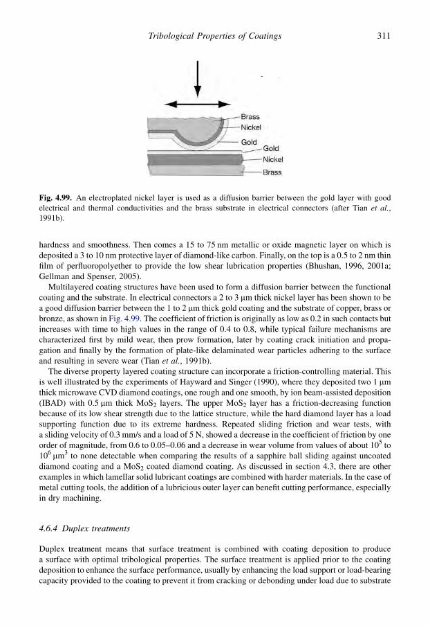
hardness and smoothness. Then comes a 15 to 75 nm metallic or oxide magnetic layer on which isdeposited a 3 to 10 nm protective layer of diamond-like carbon. Finally, on the top is a 0.5 to 2 nm thinfilm of perfluoropolyether to provide the low shear lubrication properties (Bhushan, 1996, 2001a;Gellman and Spenser, 2005).
Multilayered coating structures have been used to form a diffusion barrier between the functionalcoating and the substrate. In electrical connectors a 2 to 3 mm thick nickel layer has been shown to bea good diffusion barrier between the 1 to 2 mm thick gold coating and the substrate of copper, brass orbronze, as shown in Fig. 4.99. The coefficient of friction is originally as low as 0.2 in such contacts butincreases with time to high values in the range of 0.4 to 0.8, while typical failure mechanisms arecharacterized first by mild wear, then prow formation, later by coating crack initiation and propa-gation and finally by the formation of plate-like delaminated wear particles adhering to the surfaceand resulting in severe wear (Tian et al., 1991b).
The diverse property layered coating structure can incorporate a friction-controlling material. Thisis well illustrated by the experiments of Hayward and Singer (1990), where they deposited two 1 mmthick microwave CVD diamond coatings, one rough and one smooth, by ion beam-assisted deposition(IBAD) with 0.5 mm thick MoS2 layers. The upper MoS2 layer has a friction-decreasing functionbecause of its low shear strength due to the lattice structure, while the hard diamond layer has a loadsupporting function due to its extreme hardness. Repeated sliding friction and wear tests, witha sliding velocity of 0.3 mm/s and a load of 5 N, showed a decrease in the coefficient of friction by oneorder of magnitude, from 0.6 to 0.05–0.06 and a decrease in wear volume from values of about 105 to106 mm3 to none detectable when comparing the results of a sapphire ball sliding against uncoateddiamond coating and a MoS2 coated diamond coating. As discussed in section 4.3, there are otherexamples in which lamellar solid lubricant coatings are combined with harder materials. In the case ofmetal cutting tools, the addition of a lubricious outer layer can benefit cutting performance, especiallyin dry machining.
4.6.4 Duplex treatments
Duplex treatment means that surface treatment is combined with coating deposition to producea surface with optimal tribological properties. The surface treatment is applied prior to the coatingdeposition to enhance the surface performance, usually by enhancing the load support or load-bearingcapacity provided to the coating to prevent it from cracking or debonding under load due to substrate
Fig. 4.99. An electroplated nickel layer is used as a diffusion barrier between the gold layer with goodelectrical and thermal conductivities and the brass substrate in electrical connectors (after Tian et al.,1991b).
311Tribological Properties of Coatings

surface deformation (see Fig. 4.90). The objective of using a duplex combination of a surfacetreatment and a coating is thus to provide a synergistic effect such that the resultant performance isbetter than either of the individual entities could provide alone.
Plasma nitriding was combined with an ion-plated hard TiN coating and the improved load supportcould be demonstrated as increased higher critical load in scratch testing by Leyland et al. (1991).Good load support for the coating is crucial for achieving long lifetime in many applications. Differentkinds of surface responses can influence the limit of load support in a coated surface, as shown inFig. 4.100. It seems that a static loading test for the limit of load-bearing capacity would not beadequate, as it does not provide evidence for an increase in ploughing friction. It is therefore likelythat a controlled scratch test is the most effective way to estimate the limit of load support. That wasthe approach adopted by Matthews and co-workers in evaluating the improved performance achievedby using a plasma-nitriding process on steel and titanium alloys prior to PVD coating (Leyland et al.,1991; Matthews et al., 1995; Matthews and Leyland, 1995).
Our recent work has indicated that for the evaluation of the limit of elastic load-bearing capacitya larger sliding impressor may be needed than the standard Rockwell C indentor used in the scratchtest. With a larger radius counterface the contact area, and therefore the contact pressure, can be moreaccurately assessed. Also, whereas in the scratch adhesion test the aim is usually to penetrate thesurface, this may not be desirable in a test to evaluate the load-bearing ability. Furthermore, a largerradius counterface more accurately simulates the real contact geometry in most practical applications.Leyland et al. (1991) have demonstrated with a standard Rockwell C indenter in scratch tests that theload-carrying capacity of a hardened high-speed steel (grade ASP23) is improved by more than 25%by applying a plasma-nitriding treatment prior to TiN coating, as shown in Fig. 4.101.
Other early exponents of the duplex approach were the groups of Bell and Rie, with the latteremphasizing plasma nitriding as a precursor to a vapour deposition process. Bell and co-workers havepublished widely on the evaluation and modelling of duplex treated surfaces (Salehi et al., 1991; Bellet al., 1998a, b; Dong and Bell, 1999; Mao et al., 2007; Zhang et al., 2006a). They presented diagramsto illustrate schematically the concepts behind, and benefits of, duplex surface engineered systems.A prior diffusion treatment combined with a coating can provide a composite effect to improve thetribological response of a surface as illustrated by Fig. 4.102, based on their ideas.
Bell et al. (1998a) showed how the maximum Hertzian contact pressure limit in a twin-disk test canbe extended by the use of a duplex treatment approach, as shown in Fig. 4.103. In their early papersthey held one disk stationary to give a sliding speed of 0.3 m/sec, and they ran tests in oil underincreasing increments of load until accelerated wear took place, as evidenced by an increase in
Fig. 4.100. The surface load support is influenced by: (a) coating fracture, (b) coating debonding, (c)substrate elastic deformation, (d) substrate plastic deformation, (e) substrate fracture and (f) ploughingfriction.
312 Coatings Tribology
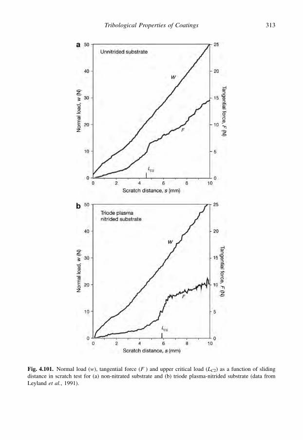
Fig. 4.101. Normal load (w), tangential force (F ) and upper critical load (LC2) as a function of slidingdistance in scratch test for (a) non-nitrated substrate and (b) triode plasma-nitrided substrate (data fromLeyland et al., 1991).
313Tribological Properties of Coatings
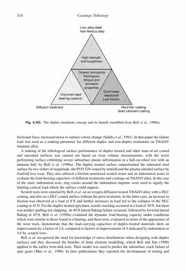
frictional force, increased noise or surface colour change (Salehi et al., 1991). In that paper the failureload was used as a ranking parameter for different duplex and non-duplex treatments on Ti6Al4Vtitanium alloy.
A ranking of the tribological surface performance of duplex treated and other state-of-art coatedand uncoated surfaces was carried out based on wear volume measurements, with the worstperforming surface exhibiting severe subsurface plastic deformation in a ball-on-wheel test with analumina ball, by Bell et al. (1998a). The duplex treated surface outperformed the untreated steelsurface by two orders of magnitude, the PVD TiN coated by tenfold and the plasma nitrided surface byfourfold less wear. They also utilized a friction monitored scratch tester and an indentation tester toevaluate the load-bearing capacities of different treatments and coatings on Ti6Al4Valloy. In the caseof the static indentation tests, ring cracks around the indentation imprints were used to signify thelimiting critical load which the surface could support.
Scratch tests were reported by Bell et al. on an oxygen diffusion treated Ti6Al4V alloy with a DLCcoating, and also on a DLC coated surface without the prior treatment. In the latter case, an increase infriction was observed at a load of 8 N and further increases in load led to the collapse of the DLCcoating at 45 N. For the duplex treated specimen, tensile cracking occurred at a load of 30 N, but therewas neither spalling nor chipping. At 40 N lateral flaking failure occurred, followed by forward lateralflaking at 45 N. Bell et al. (1998a) evaluated the dynamic load-bearing capacity under conditionswhich were similar to those found in a bearing, and these tests, evaluated in terms of the appearance ofthe wear track, demonstrate that the load-carrying capacities of duplex-treated materials show animprovement by a factor of 2.6, compared to factors of improvements of 4 indicated by indentation or5.6 by scratch tests.
Bell et al. recognized the need for knowledge of stress distributions when designing with duplexsurfaces and they discussed the benefits of finite element modelling, which Bell and Sun (1990)applied to the earlier twin-disk tests. Their model was used to predict the subsurface crack failure ofspur gears (Mao et al., 1996). In later publications they reported the development of testing and
Fig. 4.102. The duplex treatment concept and its benefit (modified from Bell et al., 1998a).
314 Coatings Tribology

modelling methods to evaluate the benefits of duplex treatments, especially on titanium alloy (Zhanget al., 2006; Kwietniewski et al., 2001; Mao et al., 2007).
A wider range of materials, including austenitic steel, Ti alloys and Co-based alloys, wereinvestigated in a study of the benefit of duplex treatment by Rie and co-workers (Rie and Broszeit,1995; Menthe and Rie, 1999; Rie, 1999). They used plasma nitriding or nitrocarburizing as a precursorto subsequent coating by PVD or PACVD techniques. They reported success by plasma nitriding orplasma nitrocarburizing different electroplated chromium coatings on steel. Those duplex treatmentsare now finding successful application on press tools (Klimek et al., 2003). There was practical success forplasma-nitrided steel followed by PACVD (Ti(BN), TiB2) coatings on die casting and forging tools(Klimek et al., 2003, 2006). Pfohl and Rie (2001) even found friction and wear benefits for TiBN and TiB2
coatings on plasma-nitrided satellite in dry sliding against 100Cr6, in a pin-on-disk test.Batista et al. (2003) examined the impact resistance of duplex and non-duplex treated hardened
AISI HI3 steel coated with (Ti,Al)N and Cr–N. The duplex (i.e. pre-plasma-nitrided) samplesexhibited at least a doubling in the scratch test upper critical load, and the number of impacts beforeadhesive failure occurred was increased by a factor of about 50 for the (Ti,Al)N coatings and around5 for the Cr–N coatings.
The possibility to plasma nitride and coat in one process was demonstrated by Michler et al. (1999),who deposited an a-C:H:Si coating onto a hardened X115CrVMo121 cold work tool steel, which waspre-plasma-nitrided in the same chamber under similar process conditions. This provided enhancedfilm adhesion and wear performance, under optimized conditions.
A novel duplex treatment combining the boost diffusion oxidation (BDO) treatment with carbon-based coatings (BDO/Cr–DLC) has been shown to significantly improve the tribological properties ofthe Ti6Al4V titanium alloy and increase the load-bearing capacity on the basis of scratch and pin-on-disk testing (Zhang et al., 2006a).
Fig. 4.103. Duplex treatment extends the contact pressure limit for a coated surface in rolling contactslike gears, bearings and cam mechanisms (modified from Bell et al., 1998a). PN¼ plasma nitriding,EB¼ electron beam, OD¼ oxygen diffusion and EBA¼ electron beam alloying.
315Tribological Properties of Coatings
There is no doubt that the idea to combine plasma treatment and coating in one process is nowgathering pace in industrial usage, especially for titanium and titanium alloy materials (Kaester et al.,2001a, b).
4.6.5 Adaptive coatings
The general concept of smart or intelligent coatings which adapt to their operating environment is onewhich has great appeal in tribology. In fact, such adaptability is a property that has existed in manycoatings for decades. One example is coatings designed to resist high-temperature corrosion in gasturbine engines. There the coating forms a protective oxide scale of varying composition, dependingon the environment, on its surface during operation. A similar situation exists for some of the mostrecently developed cutting tool coatings, based on, for example, TiAlN, which produces a stable oxideduring high-temperature cutting operations. This effect has been further enhanced in TiAlN coatingsthat contain additions of yttrium and/or chromium to help to extend oxide film stability over a widerrange of temperatures (Munz et al., 1997; Pfluger et al., 1999; Savan et al., 2000). In some ways,diamond and DLC films can also be regarded as adaptive, in the sense that the formation of atemperature-induced low shear strength layer in the contact is thought to be the source of the lowfriction demonstrated by many such coatings.
Another issue in the context of adaptive coatings is the recently renewed interest in the use of Ni–Ti,and other, e.g. copper-based, shape memory alloys as wear-resistant coatings. They are proposed asbeing suitable for MEMS devices and micro-actuators (Kneissl et al., 2003; Bhattacharya and James,1999; Fu et al., 2003; Ni et al., 2004c), due to their perceived desirable mechanical, tribological andcorrosion-resistant properties (Sheldon et al., 1988; Bouslykhane et al., 1991; Lin et al., 1997; Ni et al.,2004a, b; Zhang et al., 2005a). Such materials are known as superelastic materials. The term supere-lastic is perhaps somewhat incorrect since the elastic strain behaviour is essentially non-linear, hys-teretic and strain-path/temperature dependent. A more correct term might be pseudoelastic.
These materials can exhibit desirable wear-resistant characteristics and are claimed to have verylow sliding friction coefficients (Ni et al., 2004c). These properties are usually represented as beingdue to a reduced ploughing term during sliding contacts, that is, the unrecoverable plastic de-formation, which also absorbs frictional energy during sliding. It is nonetheless clear that a family ofmartensitic materials can be produced which exhibit thermally recoverable, if not necessarily fullytemperature-reversible, high-strain characteristics, which can provide enhanced tribological proper-ties in certain types of contacts and environments.
Some of the most promising of the these alloys are produced as coatings (Kneissl et al., 2003;Bhattacharya and James, 1999; Fu et al., 2003; Ni et al., 2004c) or surface-modified bulk materials(Sheldon et al., 1988; Bouslykhane et al., 1991; Lin et al., 1997). They comprise Ni–Ti-basedcompounds with additions of other elements – either substitutional (Kneissl et al., 2003; Bhattacharyaand James, 1999; Zhang et al., 2005c), or interstitial (Bouslykhane et al., 1991; Lin et al., 1997;Zhang et al., 2005c). They utilize the recoverability of the shape memory alloy, and also provideenhanced hardness; with the latter, in some cases, being provided by grain-size related Hall–Petchhardening. It does appear that, to gain the most effective control of friction and wear behaviour, it canstill be beneficial to deposit a coating with the desired tribochemical and hardness characteristics ontop of the Ni–Ti-based alloy (Ni et al., 2004a, b).
Zabinski and his co-workers have developed solid lubricant coatings which are capable of adaptingto temperatures from ambient up to 800�C (Zabinski et al., 1995a, b). At such high temperatures,conventional oils and greases cannot be used, and graphite and metal dichalcogenides such as MoS2
and WS2 have historically been employed as alternatives. Their lubricious nature is generallyattributed to weak interplanar bonding and low shear strength. Favourable conditions may, however,not prevail at higher temperatures, where such materials oxidize. They reported that this oxidationmay become a problem at temperatures as low as 350�C, and have carried out research into the
316 Coatings Tribology

deposition of coatings with additives such as graphite fluoride (CFx) in order to extend the permissibleoperating temperature up to 450�C. They utilized a pulsed laser deposition method, showing thatWS2/CF nanocomposite films were less sensitive to moisture than WS2 alone, achieving frictioncoefficients of 0.01 to 0.04 against a stainless steel counterface in dry air. Although not fully adaptive,in the sense of being reversible, such coatings nevertheless point the way forward toward coatingmaterials that can be effective over a wider operating range.
To provide lubricity in the higher temperature range (500–800�C), other materials must be con-sidered. Oxides such as ZnO, along with fluorides such as CaF2 and BaF2, are lubricious in thisregime, due to their low shear strength and high ductility. The oxides and, to a lesser extent, thefluorides are also chemically stable in air at high temperatures. At ambient temperatures, however,these materials are brittle and subject to cracking and high wear rates. Thus an answer to producinga lubricant coating that can operate over a broad temperature range is to combine low- and high-temperature lubricant materials uniformly dispersed throughout the coating in either a nanolayered ornanocomposite structure.
Zabinski et al. (1995b) examined both layered and composite structures of CaF2 and WS2 grown bypulsed laser deposition. Subsequent work on steel and TiN coated steel substrates illustrated that thesefilms were lubricious up to 500�C. The CaF2 and WS2 materials interacted to form CaSO4, amongother compounds. The coatings, in effect, adapted to their environment by forming a low-frictionouter layer. The adaptive or chameleon coating concept was applied to a range of DLC-based coat-ings, and it was demonstrated that nanocomposite coatings can be produced which are adaptive toload, environment and temperature (Veovodin and Zabinski, 1998a; Voevodin et al., 2002).
The concept of combining coating materials to extend the operating range has been applied usingseveral other compounds; for example MoS2 with PbO and WS2 with ZnO, to provide lubrication overa wide temperature range (Donley and Zabinski, 1994; Zabinski et al., 1996, 1992; Walck et al., 1994,1997; Zabinski and Donley, 1994). In these cases, the metal dichalcogenides reacted with the oxidesto form PbMoO2 and ZnWO4, which were found to be lubricious at high temperatures. The problemwith these coatings was that they were adaptive only on heating; that is, the low-temperature lubricantmaterials reacted to form a high-temperature lubricant – but the reaction was irreversible. Afterreturning to room temperature, the lubricious properties had disappeared.
A promising way toward reactions is to use diffusion barrier coatings with layered structures, andthereby to develop fully chameleon-like coatings, which will function reversibly through multipletemperature cycles. The ideal structure for such adaptive coatings may well be a nanodispersion ofnon-percolated, or perhaps partially percolated, active constituents. One key issue is controlling theextent of interpenetration of the constituent phase networks and thus the rates of supply and reactionof the species. This is best achieved by coatings exhibiting nanocomposite structures. Such structureshave two significant benefits for adaptive coatings. They allow control of the ingress of environmentalspecies (e.g. humidity, oxygen, etc.) and also provide a degree of control of the availability of activeconstituents. In other words, the release rate can be adapted in situ, to suit the operating liferequirements.
317Tribological Properties of Coatings

This page intentionally left blank

CHAPTER 5
Coating characterization and evaluation
Contents
5.1 The requirements 3195.2 Coating characteristics 3195.3 Property characterization and evaluation 323
5.1 The Requirements
In previous chapters we discussed several of the methods available to produce coatings and describedhow they behave tribologically. In this chapter we turn our attention to the techniques used to ascertainwhat has been produced, its physical properties and how it performs. The goals of surface charac-terization and evaluation can be addressed by a wide range of techniques. The relative importancegiven to different properties depends on a number of factors, such as a coating’s level of development,e.g. the need for further optimization, and the intended application. A coating in full production fora number of years may be subjected to less rigorous testing than one which is newly introduced.Indeed, the emphasis moves towards non-destructive methods when the coating is applied toa product.
The relative importance of each surface coating property to be characterized and evaluated is thususually different depending on whether the coating to be studied is in production or is still underresearch and development. The emphasis in the former case is on quality control and repeatability,whereas the latter is aimed towards the evaluation of specific properties and the way in which they areinfluenced by process variables.
Thus, for example, adhesion and thickness become key properties once a coating has been opti-mized and is in production, whereas the friction and wear performance and composition are usually ofmost interest when a tribological coating is under development. Ultimately, there will be a need fora standard specification for any coating, since only with a defined standard can the design engineer, orother person who specifies a coating, actually communicate what is required.
Intrinsic coating properties need to be measured due to the move towards computer databases oncoatings which aid both in their selection and in the modelling and prediction of coating behaviour.These factors all increase the need for effective, precise and repeatable property measurement (Godetet al., 1992; Strafford and Subramanian, 1997; Jennet and Gee, 2006).
5.2 Coating Characteristics
5.2.1 The surface
The surfaces of coatings, like the surfaces of bulk materials, have particular attributes which maydiffer from those of the material within the coating. For example, a chromium coating will generallyhave an oxide film at the surface. Similarly, as with a bulk material, a coating which has beensubjected to a final mechanical treatment, such as polishing, may exhibit the effects of near-surfacedeformation. It is important to be aware of these localized variations in the nature of coatings,
319

especially since this is where the immediate contact with the counterface occurs. Effects such aswettability, adsorption and chemisorption are controlled by the immediate surface, or more correctlythe interface between the coating and its counterface – be that solid, liquid or gas (Iliuc, 1980; Abeland Ferrante, 2001).
Equally important are the geometrical properties of surfaces and especially their topography. Withcoatings, the subject takes on a new significance, since the deposition method may sometimes sig-nificantly influence the surface topography. Some coating methods, such as electroplating, can smooththe surface. Other methods such as some thermal spraying techniques can lead to a roughening, whileothers may impart a specific and distinct type of topography, such as the faceted type exhibited byCVD diamond films.
Given this range of topographies it is particularly important to utilize appropriate surface roughnessparameters when characterizing coated surfaces. Indeed, for certain types of coatings, such as thoseused in optical devices, it has been necessary to develop new techniques for the investigation ofsurface topography, even on an atomic scale, and these are referred to later.
5.2.2 Thickness
This, apparently simple, property has a criticality which many practitioners have failed to recognize,especially in tribological applications. There is a complex interplay between effects such as the in-trinsic stress within a coating, the hardness of the coating and the substrate and the adhesion to thesubstrate which must be optimized, essentially by the appropriate choice of thickness (see Chapter 3).It can also be represented by concepts such as ‘mass thickness’, which seeks to recognize that filmshave varying densities and porosities (Pulker, 1984). Thus simple step-height measurements ofthickness could in many applications be meaningless without a quantification of density or porosity.
When dealing with surface treatments, such as nitriding or ion implantation, the definition ofthickness or treatment depth is even less clear. Usually, in the former case the depth is taken to be thatat which the layer hardness falls to a level one-third above the core hardness of the bulk material.
5.2.3 Adhesion
Adhesion is the ability of a coating to remain attached to the substrate under the required operatingconditions and this is clearly vital. Many use the words ‘adhesion’ or ‘bond strength’ to describe thisability, but the subject is much more complex than the description of a single strength parameter mightsuggest. The adhesion between the coating and the substrate should not be mixed up with the adhesionbetween the coating top surface and the sliding counterface, which is related to adhesive friction andadhesive wear.
Failure of coating adhesion to the substrate results in interfacial debonding which for brittlematerials is often called cracking. The crack nucleation and propagation to larger surface failure is dueto local load levels and directions, resulting stress conditions, strain and deformation. Sometimesa failure that is referred to as adhesive may in fact be a cohesive failure when the cracking occurs inthe coating or in the substrate. Indeed, the complexity is such that it is unlikely that any one measureor test can satisfactorily differentiate between the ability of different coatings to stay bonded todifferent substrates under different application conditions. We are even further away from a test whichwill assess this non-destructively.
As an example of the above statement, consider a highly columnar and relatively porous PVDcoating, compared to a more dense and cohesive one. In a test designed to assess adhesion bystretching or bending the substrate to put the coating in tension, the columnar coating is more likely toremain adherent, since it will simply crack along column boundaries. The dense cohesive film will,however, experience greater interfacial stress levels between coating and substrate, and is more likelyto debond, even if the absolute bond strength between coating and substrate is greater. Conversely, in
320 Coatings Tribology

a sliding contact the latter coating is likely to remain in place, whereas the former will be more friableand will probably be rapidly removed from the substrate.
From a scientific point of view it is preferable to think of adhesion as a fundamental property whichcan be quantified according to known data about atomic binding forces, as shown in Fig. 5.1. Breakingthe bonds between the coating and the substrate will produce a lateral crack. The growth of this crackis equivalent to crack growth in fracture mechanics and thus the term interfacial fracture toughness isincreasingly used to describe the strength of coating adhesion, see section 5.3.3.
The definition of adhesion used by the American Society for Testing Materials (ASTM, 1970) is‘the state in which two surfaces are held together by interfacial forces which may consist of valenceforces or interlocking forces or both’. It was the recognition of the inadequacies of a theoretical oridealized view of adhesion that led Mittal (1976) to define the term ‘practical adhesion’, as opposed to‘basic adhesion’, to take account of extraneous factors such as the internal stress within the film or thepresence of defects. However, as the practical adhesion will be application or test method dependent,it has been suggested that an alternative term might be ‘effective adhesion’ or even ‘surface systemadhesion’, to take account of the fact that different surface loading conditions can result in differentmechanisms for coating debonding from the substrate. Thus, in establishing any measure of relativeability for a coating to remain attached to a substrate it is important to define precisely the contactconditions. The basic mechanisms of coating adhesion to substrate have been the subject of several in-depth studies such as Thouless (1988), Bull (1992), Bhushan (1999b), Maugis (2001) and Malzbenderet al. (2002).
5.2.4 Morphology
The various coating methods produce structures or morphologies which are specific to themselves.The vapour deposition methods, due to their widely variable process conditions, which include thepossible use of plasma or ion assistance, were from an early date studied in terms of the influence ofdeposition conditions on structure (Movchan and Demchishin, 1969; Anderson, 1971; Thornton,1977). The model put forward by Thornton is now widely referred to, in terms of the structure zoneswhich he classified as shown in Fig. 2.7. With the homologous temperature – the substrate temper-ature divided by the melting point of the coating in absolute units – as one axis, and pressure as theother, Thornton described the following zones for sputter-deposited films.
Fig. 5.1. Relative bond strengths for a range of possible interfacial binding forces (after Bull, 1992).
321Coating Characterization and Evaluation

Zone 1 consists of tapered crystallites and is not fully dense, having longitudinal porosity betweenthe grains. Zone T is a transition zone consisting of fibrous grains, still with weak boundaries. Zone 2is a fully dense columnar structure and Zone 3 is an equiaxed grain morphology. The temperatureratios cited by Thornton are not appropriate for plasma- or ion-assisted deposition methods, which canoften produce extremely dense films at very low homologous temperatures, e.g. <0.2 for ceramicssuch as titanium nitride. For reasons of its apparent non-applicability in many cases, the Thorntonmodel has been criticized in the literature. However, as a means of describing structures it remainsa useful tool which is still widely used to categorize the structure of vapour-deposited coatings.
The structures exhibited by the coating processes carried out using molten or semi-molten stateprecursors differ considerably from those in the Thornton diagram. This is described by Rickerby andMatthews (1991a). The molten or semi-molten state processes typically produce coatings with splat-like features whose boundaries tend to be parallel rather than perpendicular to the substrate surface.Coating properties such as hardness, elastic modulus and residual stress are all influenced by thestructure, as indeed is the tribological response.
The influence of the zone structure on sliding wear behaviour for a coating, such as TiN on steel,has been postulated (Bull et al., 1988b; Rickerby and Matthews, 1991b; Kelly et al., 2006). Thisdemonstrates that composition is not the only important parameter in determining the effectiveness ofcoatings, an observation also made by Matthews and Sundquist (1983), who reported several titaniumnitride-based coatings which showed quite different tribological properties, influenced not only by thephase composition but also by the morphology and even the crystallographic preferred orientation.
5.2.5 Composition
There are many methods available which provide chemical composition and other information aboutcoatings. As pointed out by Ferrante (1982) the range of techniques has led to a plethora of acronyms,some of these will be elaborated in section 5.3.4. However, simple chemical composition is nota sufficient indication of a coating’s properties to enable its tribological behaviour to be predicted witha satisfactory degree of confidence. This is especially true in the case of ceramic coatings.
As we have seen, coatings can be composed of grains, i.e. they can be polycrystalline, eitherrandom or textured and have a preferred orientation, they may even be epitaxial, or in some cases theymay be amorphous (Bhushan, 1999b).
The appropriate analysis technique for a particular coating will thus depend on its morphologicalnature, as well as aspects such as its thickness, surface finish and actual composition. In tribology,increasing attention is being focused on tribochemical reactions, and the choice of surface analyticaltechnique will also be determined by its ability to detect and evaluate the reaction products andtransfer layers which often control contact behaviour.
5.2.6 Wettability
In addition to the chemical reactivity of a surface, the surface tension, or surface energy may be ofimportance. This is frequently measured as the contact angle between the air and the liquid ofa droplet on a surface, which defines the wettability of the surface. This has been recognized assometimes being an important factor influencing its tribological characteristics. It influences thebehaviour of any liquid lubricants present. It can affect thermal transfer, such as in heat exchangersystems, and increasingly it is being studied in terms of the ability of surfaces to ‘self-clean’ (Furstneret al., 2005).
The physical background to wettability and its measurement has been explained by Iliuc (1980),Bhushan (1999b) and Vizintin (2004). Although usually simply determined by the contact angle ofa droplet of liquid in contact with a solid surface, in practice the wetting angle is a thermodynamicvariable which Iliuc states can be used to determine a so-called ‘wetting energy’ which is given by the
322 Coatings Tribology
adhesion energy of the solid/liquid interface minus the liquid surface tension. The wettability isinfluenced by the surface state, e.g. the roughness, its degree of cleanliness and the degree of oxi-dation, and it can be assumed that both friction and wear can be affected by changes in the wettabilityor hydrophobicity of a surface.
Especially, since the surface energy of a material depends on the nature of the medium on eitherside of the material boundary, it is clear that the wettability of a surface is subject to changes in theoperating environment.
When considering the subject of wettability in tribology, there is a tendency to think of liquid/solidcontacts at the non-elevated temperatures experienced by lubricants (Podgornik et al., 2007; Borrutoet al., 1998). In fact wettability can also be important at very high temperatures, for example whendealing with coatings which must resist attack from molten metals, as in die-casting operations (Salaset al., 2003). In that case, there is a need to consider the wettability performance as well as the wearresistance, since the degree of wetting influences the degree and extent of attack by the molten metalon the die surface.
However, Podgornik et al. (2007) found in their investigation of DLC and W–DLC coated steelsurfaces, sliding against a similar surface on steel crossed cylinders, that there was no directcorrelation between surface energy, wettability of the surface and tribological performance of the oillubricated surface.
A correlation between ultra-low friction, m< 0.05, low wear and high contact angle of carboncoatings has been reported by Rha et al. (2005). Changes in wetting angle had a remarkable influenceon silver wear debris agglomeration and the tendency of contact patch formation in ball-bearingtesting of silver coated upper and lower bearing races (Yang et al., 2001).
In the field of biological applications for tribological coatings, the degree of wetting, for exampleby the lubricant used to mimic the in vivo conditions, has been shown to influence the friction andwear performance (Kwok et al., 2005; Gispert et al., 2006). This indicates that the selection ofa coating with the appropriate wetting characteristics is important to the life and functionality ofprosthetic devices. Indeed, the coating selection issues in such cases are particularly stringent due tothe need to utilize biocompatible coatings (Sunny et al., 2005) and avoid toxic materials which may beharmful, as discussed in section 7.11.
5.2.7 Residual stress
Tribological coatings often contain residual stresses, which can be advantageous or disadvantageous,depending on the level of stress and the application. For example, a high compressive stress in-planewith the coating can lead to coating detachment, particularly in PVD coatings if the stress increaseswith thickness, and this can limit the thickness of coating which can be used. Conversely, an in-planecompressive stress can ensure that any incipient cracks normal to the surface do not open when thecomponent is subjected to stress, particularly cyclic stresses, and this can extend the fatigue life. Therole of residual stresses in coated surfaces on their tribological performance is discussed in detail insection 3.2.10.
5.3 Property Characterization and Evaluation
To achieve an optimal design of a coated surface we need to know its key characteristics and how itwill behave in different loading conditions. Theoretical models are a good start but they need to beconfirmed empirically. In production, adequate test methods are needed for quality assurance of thecoated surface before it is taken into use. Various aspects of surface property evaluation have beendiscussed by Bunshah (1982), Hintermann (1983b), Matthews and Holmberg (1992) and Jennet andGee (2006) and problems with quality assurance assessment by Bull et al. (1991) and Weiss (1991).
323Coating Characterization and Evaluation
5.3.1 Roughness
Surface roughness is typically characterized using a stylus profilometer. This method is widely useddespite its limitations, brought about chiefly by the need to have a relatively blunt stylus, as discussedby Hutchings (1992). The main roughness parameters are defined below and their usefulness ina tribological sense has been discussed in Chapter 3.
The main parameters used are the peak to valley height, Rt, and the centreline average value, Ra,which is the arithmetic mean value of the vertical deviation of the profile from the centreline. Alsoused is the root mean square value, Rs, which is the square root of the arithmetic mean of the squaresof the deviations from the centreline. Although most engineering surfaces tend to give a Gaussiandistribution of texture heights, other distributions are possible. Typical fine ground surfaces used forPVD coatings tend to be Gaussian but can be negatively skewed due to gouging features caused by theaction of welded grits (Stout et al., 1990). The coating will tend to fill such troughs, thereby improvingthe finish, but the exact effect of the coating depends on its own topography.
For very soft films the profilometer stylus may actually scratch the surface. In order to avoid suchstylus-related problems, non-contacting optical methods of profile assessment have been developed.One such is described by Bhushan and Gupta (1991). It consists of a microscope, an interferometer,a detector array and support electronics. The surface profile measurement is based on two-beamoptical interference and requires a reference surface which is mounted on a piezoelectric transducerpermitting the use of phase shifting techniques to measure the phase of the interference pattern, whichis proportional to the height at that location. Another means of profile assessment based on opticalprinciples is confocal scanning microscopy (Gee and McCormick, 1992), which uses a tandemscanning microscope and the principle of convocal imaging to provide a 3D topographic image. Bothof these optical methods thus provide a highly sensitive means of characterizing surface profiles.
Even more sensitive is the Scanning Tunnelling Microscope (STM) (Kumar Wickramasinghe,1989). This senses atom-scale topography by monitoring the flow of electrons which ‘tunnel’ acrossthe gap between a probe and the surface. Piezoelectric ceramics can be used to manoeuvre the probe inthree dimensions, thereby allowing an image of the surface to be built up on an atom by atom basis.Another sensitive device is the Atomic Force Microscope (AFM), which, unlike the STM, can probeinsulating surfaces. This also involves scanning the surface with a probe, but in this case a repulsiveforce which varies with relief deflects the tip, the movement of which is monitored by a laser beamwhich is in turn monitored by a feedback control to provide near atomic-scale images. Various otherscanning probe microscopes are under development and considerably improve our understanding ofsurfaces and their behaviour (Bhushan, 1999b, 2001e).
5.3.2 Thickness
The thickness of a thin layer on a surface can be measured by a largevariety of different methods as shownin Fig. 5.2. The bottom three of these give a composite reading which relates to both thickness and density.
Even if some of the thickness measurement methods can achieve great accuracies, they all haveboth strengths and weaknesses. X-ray fluorescence requires careful calibration, but is particularlyuseful in a coating facility where nominally identical coatings are being produced. Multilayeredcoatings can present problems due to differences in defining the substrate surface. Direct observationof sections by optical or scanning electron microscopy can avoid this, but this suffers from thedrawback that the component must be cut to produce the section. One of the most accurate methods isto use a step-height measurement facility on a stylus profilometer – which of course necessitatesleaving or producing an uncoated region, over which the step can be measured.
Optical techniques are also available, but they are usually for transparent films. An interferencetechnique for thickness measurement of opaque coatings is sometimes used. This also requires a step
324 Coatings Tribology

to be left by masking during coating. There are various other methods of thickness assessmentavailable commercially, based on electrical, magnetic or electromagnetic principles. These aregenerally suitable for thicker films, as are techniques based on gravimetric measurements. Furtherinformation on coating thickness measurements is given in Bhushan and Gupta (1991).
A comparison offour common coating thickness measurement methods shows that the ball crater method(see later), the step profilometer and the scanning electron microscope (SEM) all give thickness results withsatisfactory accuracy, while weighing usually underestimates the thickness – as shown in Fig. 5.3.
The subject of laboratory coating thickness measurement repeatability and reproducibility is fur-ther demonstrated by a set of trials which was carried out at three different laboratories: the Universityof Hull (UH), the Technical Research Centre of Finland (VTT) and the Technical University ofDarmstadt (THD) (Ronkainen et al., 1990a, b). Three coating types, A, B and C, were produced atthese laboratories on ASP23 tool steel hardened to 64 Rc and polished to 0.4 mm Ra. Coatings A and Bwere titanium boron nitride compound films produced by dc plasma-assisted electron beam reactiveevaporation and rf magnetron sputtering, respectively. Coating C was a titanium aluminium nitridefilm produced by dc plasma-assisted electron beam and resistive evaporation.
For thickness measurements the ball crater method was chosen as a simple, cheap and easy to usetechnique. The principle of the ball crater measurements are shown in Fig. 5.4. The ball diametersused were 25.4 mm at UH and THD, and 30.0 mm at VTT. A kerosene–diamond suspension was usedas the abrasive medium. The following expression was used to assess the thickness:
Thickness ¼ x $y
ball diameter(5.1)
Measurements of x and y were made at UH using a Shinko profile projector, at VTT using an OlympusBH-2 microscope and at THD using the measurement facility on a Leitz Miniload microhardness tester.
Fig. 5.2. Different methods of measuring the coating thickness (after Weiss, 1991).
325Coating Characterization and Evaluation

Each laboratory produced one crater, from which four determinations of thickness were made, to obtaina mean and standard deviation value. All craters were located within a 4 mm by 5 mm area on eachsample. Further details of the ball crater technique are given in Valli et al. (1985b). Figure 5.5 shows themean thickness values for each coating found from ball cratering. The error bars represent standarddeviations. Agreement between the mean values was considered good, being typically within 4%.
5.3.3 Mechanical evaluation
5.3.3.1 Hardness
The material parameter towhich we give the title hardness is not an intrinsic material property. However, thisparameter reflects well the resistance to plastic deformation when a well-defined and sharp tip, the indenter,is forced into the surface. In real engineering materials the hardness is influenced by grain boundary effects,flaws and a complex interaction of response behaviours which result in the value measured varying arounda mean. The nature of the basic test, involving the measurement of the dimensions of an indentation left afterthe removal of an indenter, also introduces some subjectivity to the reading. Nevertheless, hardness is one ofthe simplest properties to measure and it is widely used as a ranking parameter when comparing coatings.
The hardness test is a useful tool for process control, being especially useful for comparing similarfilms, without having to carry out special specimen preparation. It can also, in suitably developedform, provide information on the elastic properties (Bull and Rickerby, 1991; Jennet and Gee, 2006).
The most common hardness measures used for coatings are the Vickers or the Knoop micro-hardness, typically using loads of between 10 and 500 g. These differ in the shape of the diamond usedfor indentation, as shown in Fig. 5.6.
Many authors use different conventions when measuring or reporting hardness levels. In this book,when quoting hardness levels, we are mainly using the unit GPa or we adopt the units used by theoriginating author.
Fig. 5.3. Comparison of thickness measurement results of four different coatings performed by the ballcrater method, SEM, weighing and step profilometer (data from Valli et al., 1985b).
326 Coatings Tribology

As an illustration of the variability which can occur in hardness test readings we shall refer to theround-robin experiment mentioned earlier in section 5.3.2. Hardness tests at UH and THD were carriedout using a Leitz Miniload microhardness tester, and at VTT using a PMT3 machine. A Vickersmicroindenter was used in each case. Loads of 15, 25, 50 and 100 g were used, with an indentation dwelltime of 10 seconds. Each laboratory made five indentations at each load on each of the three differentcoatings, within a specified area of 20 mm� 5 mm. The mean and standard deviation of the hardnessnumber was determined from each group of five indentations by one person at each laboratory.
The results are shown in Fig. 5.7. The error bars represent standard deviations, and as can be seenthere are considerable variations in the absolute values in some cases and even in the mean valuesmeasured at different institutions, under nominally identical conditions. These test results endorse theview expressed earlier, that hardness readings should be treated with caution, and exact test conditions– especially the load – should be specified. In this particular case, the substrate had an influence on themeasured values, which may have increased the variability.
A general rule of thumb often applied is that, when measuring coating hardness directly on thesurface, the indentation depth should be less than one-tenth of the coating thickness, to ensure that the
Fig. 5.4. Schematic views of the ball crater apparatus and the crater profile.
327Coating Characterization and Evaluation

Fig. 5.6. Geometry and indentation with (a) a Vickers indenter and (b) a Knoop indenter.
Fig. 5.5. Coating thickness measurements by the ball cratering method in three different laboratories (datafrom Ronkainen et al., 1990b).
328 Coatings Tribology

Fig. 5.7. Vickers hardness measurements carried out in three different laboratories for two titanium boronnitride films (A and B) and one titanium aluminium nitride film (C) deposited on tool steel by PVDmethods (data from Ronkainen et al., 1990b).
329Coating Characterization and Evaluation

substrate effect is minimized. Since the Knoop indenter penetration is shallower than the Vickers fora given load, this means that this test should have a wider applicability, especially for thin coatings.
A number of authors (Sargent and Page, 1978; Jonsson and Hogmark, 1984; Vingsbo et al.,1986; Burnett and Rickerby, 1987b) have noted an indentation size effect (ISE) on the hardnessreadings measured, which tends to show a higher hardness with decreasing load. One reason for thiscan be elastic recovery of the indentation, another is the decreasing effect of grain boundaries andfracture.
For the Vickers pyramid indenter the hardness value is defined as the load divided by the surfacearea of the impression, whereas for Knoop it is the load divided by the projected area of the im-pression. Ignoring elastic recovery can lead to large errors in the hardness value measured at low loads(Bull and Rickerby, 1991). A general expression for hardness is
H ¼ c $ w
d2(5.2)
where w is the load applied, d is the indentation diagonal length measured and c is a constant. When wis in kg and d in mm then c¼ 1.854 for the Vickers test and 14.23 for Knoop.
An expression quoted by Bull and Rickerby to quantify the influence of indentation size is
H ¼ k$dm�2
(5.3)
In this case k is a constant and m is known as the indentation size effect (ISE) index.For a more comprehensive model of coating hardness, which attempts to eliminate the influence of
the substrate, it is useful to adopt a law of mixtures approach. Jonsson and Hogmark (1984) used anarea law of mixtures to model the composite hardness Hcomp measured in the Vickers test thus
Hcomp ¼Ac
A$ Hc þ
As
A$ Hs (5.4)
where Ac and As are the load-support areas of the coating and substrate and A is the projected area ofthe indentation.
Sargent (1979) suggested a volume law of mixtures, which was extended over the years by Burnettand Page (1984), Burnett and Rickerby (1987b), Bull and Rickerby (1990b), Korsunsky et al. (1998)and Bull et al. (2003a, 2004). In this model the deformation beneath the Vickers indenter is modelledas a hemisphere and the volumes of the portions of the total deforming volume that lie in the coating,Vc, and the substrate, Vs, are taken into account to give
Hcomp ¼Vc
V$ Hc þ
Vs
V$c$ Hs (5.5)
where Hc and Hs are the hardness of the coating and substrate. c is an empirical interface parameterrepresenting the modification to the deforming volume in the softer substrate, due to the constraintfrom the harder coating.
The total deforming volume is
V ¼ Vc þ c3 $ V5 (5.6)
In practice of course it would be preferable to have a means of assessing the coating hardnesswithout the need for such models. One way to do this is to ensure that the load applied is so low thatabsolutely no substrate effect is possible. Also an ideal test would allow the influence of elasticrecovery to be assessed.
These goals are sought in the nanoindentation test, which senses penetration depth during testing,rather than relying on the measurement of a residual impression left after the load has been removed(Pethica et al., 1983; Ross et al., 1987; Pollock, 1992; Tayebi et al., 2004a, b). Typically,nanoindentation machines operate in the mN load range and can continuously monitor load and
330 Coatings Tribology
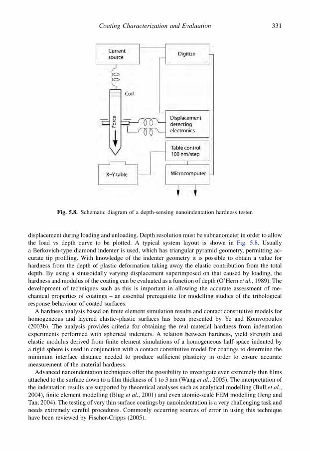
displacement during loading and unloading. Depth resolution must be subnanometer in order to allowthe load vs depth curve to be plotted. A typical system layout is shown in Fig. 5.8. Usuallya Berkovich-type diamond indenter is used, which has triangular pyramid geometry, permitting ac-curate tip profiling. With knowledge of the indenter geometry it is possible to obtain a value forhardness from the depth of plastic deformation taking away the elastic contribution from the totaldepth. By using a sinusoidally varying displacement superimposed on that caused by loading, thehardness and modulus of the coating can be evaluated as a function of depth (O’Hern et al., 1989). Thedevelopment of techniques such as this is important in allowing the accurate assessment of me-chanical properties of coatings – an essential prerequisite for modelling studies of the tribologicalresponse behaviour of coated surfaces.
A hardness analysis based on finite element simulation results and contact constitutive models forhomogeneous and layered elastic–plastic surfaces has been presented by Ye and Komvopoulos(2003b). The analysis provides criteria for obtaining the real material hardness from indentationexperiments performed with spherical indenters. A relation between hardness, yield strength andelastic modulus derived from finite element simulations of a homogeneous half-space indented bya rigid sphere is used in conjunction with a contact constitutive model for coatings to determine theminimum interface distance needed to produce sufficient plasticity in order to ensure accuratemeasurement of the material hardness.
Advanced nanoindentation techniques offer the possibility to investigate even extremely thin filmsattached to the surface down to a film thickness of 1 to 3 nm (Wang et al., 2005). The interpretation ofthe indentation results are supported by theoretical analyses such as analytical modelling (Bull et al.,2004), finite element modelling (Blug et al., 2001) and even atomic-scale FEM modelling (Jeng andTan, 2004). The testing of very thin surface coatings by nanoindentation is a very challenging task andneeds extremely careful procedures. Commonly occurring sources of error in using this techniquehave been reviewed by Fischer-Cripps (2005).
Fig. 5.8. Schematic diagram of a depth-sensing nanoindentation hardness tester.
331Coating Characterization and Evaluation

5.3.3.2 Elastic modulus
The elastic modulus or Young’s modulus, E, is normally calculated based on an analysis of theunloading curve of the nanoindentation test. It is assumed even for materials which exhibit plasticdeformation during loading that the initial unloading is elastic. Thus the initial slope of the unloadingcurve is directly related to the elastic modulus. The following formula developed by Oliver and Pharr(1992, 2004) can be used for the reduced elastic modulus,
Er ¼ffiffiffiffiffiffiffiffip$Sp
2$ffiffiffiAp (5.7)
where S is the slope of the unloading curve at the point of maximum load and A is the projected area ofcontact between the indenter and the material at that point, as illustrated in Figs 5.9 and 5.10. Theslope of the unloading curve S is estimated as shown in Fig. 5.10.
The projected contact area is obtained from the contact depth, hc, which can be expressed as
hc ¼ hmax � 3 $ wmax=S (5.8)
where hmax and wmax are as shown in Fig. 5.10 and 3 is a constant that depends on the geometry of theindenter. 3¼ 0.72 for a conical, 0.75 for a spherical and 1 for a flat indenter. The contact area isgenerally a function of the contact depth
A ¼ A�hc
�(5.9)
where for a perfectly sharp Berkovich or Vickers indenter A(hc) ¼ 24.5 $ hc2. The elastic modulus, E,
can be determined from the above equations and using the available information of the Poisson’s ratioof the materials from the equation
1
Er¼ 1� v2
i
Eiþ 1� v2
E(5.10)
where Ei and ni are the elastic modulus and Poisson’s ratio of the indenter material.Some limitations of this method have been pointed out by Malzbender et al. (2002). When a
material exhibits pile-up or sinking-in, the estimated contact depth, and hence the projected area, iseither underestimated or overestimated. This is typical for metals that show strain hardening. Also, theequations are not applicable for materials that creep substantially.
For a coated surface the effective elastic modulus is a combination of that of the coating and thesubstrate. As for hardness, the indentation depth should be less than one-tenth of the coating thicknessto obtain E values for the coating that are without significant influence of the substrate. The most
Fig. 5.9. Schematic representation of a section through an indentation using a conical indenter.hc¼ contact depth, hs¼ sink-in depth and hf¼ final depth.
332 Coatings Tribology

accurate measurements are done with small indentation depths and a sharp indenter. Models used formeasuring elastic modulus of a coated surface have been described by Malzbender et al. (2002).
Cantilever and beam methods can be used in the determination of elastic modulus of a coating(Taube, 1992). Typically, free-standing cantilevered microbeams of the substrate with the film on itare prepared. The load/deflection data from measurements in a nanometre-indention system can beused to determine both the in-plane elastic modulus and the yield strength of the coating material. Thein-plane elastic modulus can differ from that measured by indentation. Also, the yield stress of thecoating can be measured directly by this technique. Recently, laser acoustic methods have been usedincreasingly for measurement of the elastic modulus of coated surfaces (Schneider and Schultrich,1998; Schneider et al., 2002).
Although much of the literature on hardness and elasticity evaluation relates to hard ceramiccoatings there is also interest in softer films, especially solid lubricants, such as MoS2 (Gardos, 1990;Muller et al., 1989). Gardos in particular has investigated a number of layered hexagonal lubricantsfor their mechanical properties and has demonstrated their anisotropic behaviour, which of course iscritical to their tribological properties.
5.3.3.3 Fracture toughness
At present there is neither a standard test procedure nor a standard methodology for assessment offracture toughness of thin coatings. In the literature there have been several different attempts todevelop such measurement techniques but so far they all have limitations in some respect. Some of themethods can also be used to estimate the residual stress in the coating. The indentation and scratchtesting have commonly been used for qualitative assessment. Quantitative measurements have beendone by bending, buckling, indentation, scratching and tensile testing. The methods are either stressbased or energy based and today the latter approach seems to be more advantageous. Recent criticalreviews of these methods have been published by Malzbender et al. (2002), Zhang et al. (2005a) andCheng and Bull (2007).
In an indentation test of a brittle surface a pattern of cracks is generated on the surface. Radialcracks are more likely to occur at low loads when the tip is sharp, while picture-frame cracks areformed at high loads or when a blunt tip is used (Palmqvist, 1957, 1963; Cheng and Bull, 2007). Thefracture toughness of the coating or the coated surface can be calculated by combining observations ofthe cracks, load–displacement curves and stress or energy models. It has been shown for bulk
Fig. 5.10. A typical load–displacement indentation curve.
333Coating Characterization and Evaluation
materials (Lawn et al., 1980) that there exists a simple relationship between the fracture toughness,Kc, and the crack dimensions in Vickers and Berkovich indentation
Kc ¼ 3$
ffiffiffiffiE
H
r$
wpffiffiffiffiffia3p (5.11)
where wp is peak indentation load, a is the length of radial cracks and 3 is an empirical constant whichdepends on the geometry of the indenter. Lawn and Evans (1977) analysed the indentation of mediancracking for bulk materials with a Vickers indenter at elastic–plastic indentation. They developed thefollowing equation for the critical load, wc, for crack initiation
wc ¼ 21:7 $103 $ K4lc=H3 (5.12)
where KIc is the fracture toughness and H the hardness of the surface material. The factor 21.7 $ 103
was theoretically derived by considering a Vickers indenter geometry. The same factor can be used fora Berkovich indenter since the projected contact area is the same at same indentation depth.
Another commonly used relationship (Broek, 1997) for the fracture toughness and the residualstress includes the length of the radial cracks due to indentation by Vickers or Berkovich indenter andcan be expressed as
KIc ¼ cr$wffiffiffiffiffia3p þ Z$sres$
ffiffiffiap
(5.13)
where a is the length of the cracks, Z is a crack shape factor and sres is the residual stress in thesurface. The parameter cr is related to the size of the plastic zone and for Vickers and Berkovichindenters is
cr ¼ 0:016:
ffiffiffiffiE
H
r(5.14)
The results are only reliable when the radial cracks are significantly larger than the lateral size of theplastically deformed zone. The parameter Z that depends on the depth of the radial cracks isapproximately
Z ¼1:12$
ffiffiffipp
$d
a3$p
8þ p
8$d2
a2
(5.15)
where d is the depth of the crack. It is commonly assumed that the crack has a semicircular shaperesulting in d¼ a and Z¼ 1.26.
The above methods have been developed for bulk materials and can strictly only be applied forcoatings if the stress intensity is not influenced by the substrate. Malzbender et al. (2002) hasshown how the methods can approximately be applied also for coated surfaces. A differentapproach has been developed by Li et al. (1997) and Li and Bhushan (1998). They introducea method for calculating the fracture toughness for thin coatings by analysing the energy releaserate in indentation cracking and estimate the energy release from a step observed during theloading cycle of a load–displacement curve in indentation. They show that this method can beused for coatings even as thin as 400 nm. Further analysis and developments of the energy-basedmodels for fracture toughness calculation of thin coatings has been presented by Cheng and Bull(2007).
In scratch testing a spherical indenter moves with increasing load over the surface and results ina more complicated crack pattern as discussed in section 3.3.5. Malzbender and de With (2000c)tested various theories for prediction of the critical load for formation of cone cracks in scratch testing
334 Coatings Tribology

of hybrid organic–inorganic coatings on glass. They found that a simple brittle fracture model wassufficient to estimate the depth of a flaw that leads to fracture.
Holmberg et al. (2003) developed a three-dimensional finite element model for calculating thestresses resulting in surface cracking in the scratch test, described in section 3.2.8. They analysed thecontact conditions and concluded that the fracture toughness of the coating can be calculated inscratch testing by the simple equation
Kc ¼ s$
ffiffiffir
2
r(5.16)
where s is the tensile stress in the coating calculated by the FEM model and r is the crack spacing(see Fig. 3.58). This applies when the crack spacing is of the same order as the crack length whichmeans that the density of the crack field is high enough to dominate over the effect of crack length.
Bend testing has been used for fracture toughness measurement of thick freestanding films ina very similar way as for bulk materials. In some investigations a precrack has been introduced intothe coating of a coated surface (Jaeger et al., 2000) and this has enabled calculation of the fracturetoughness of the coating in bend testing. However, the introduction of a precrack of a known size ina coating as thin as typical CVD and PVD coatings is not easy. Another approach is to carry outbending without a precrack and measure the ‘cracking resistance’ that is indirectly used as a mea-sure for fracture toughness. The cracking resistance is defined as the threshold strain over whichdensity of the cracks sharply increases. Zoestberger and De Hosson (2002) used the four point bendtest for measurements of crack resistance in TiN, Ti(C,N) and TiN/TiAlN multilayer coated steelsurfaces.
Wiklund et al. (1997a, b) developed a four point bend test small enough to be placed into an SEMand be observed in situ. They used both acoustic emission and direct observations to detect the coatingcracking of TiN and CrN coated high-speed steel surfaces and obtained with both methods virtuallyidentical values for cracking resistance. However, the acoustic emission method is much faster andeasier to perform. SEM observation, on the other hand, allowed a more straightforward interpretation.The development of acoustic microimaging of cracks makes it possible to detect and image surfacecracks with very small dimensions down to crack widths in the range of 10 to 100 nm (Thomas, 2005).
The measurement of the interfacial fracture toughness, that is, the resistance to crack growth ofa lateral crack in the interface between the coating and the substrate, has been carried out bya buckling test where a buckling load was applied on an axially compressed plate of changing width(Malzbender and de With, 2002). Tensile testing of coated surfaces has been performed by someinvestigators reviewed by Zhang et al. (2005a).
5.3.3.4 Residual stress
The residual stress in a coating can be estimated by measuring the length of radial cracks inindentation as discussed in the section above. The limitations for residual stress measurement are thesame as for estimating the fracture toughness.
A common method to separately measure the residual stresses in a coating is the deflection method.The coating is deposited on a thin plate, e.g. a silicon wafer, and the curvature of the plate afterdeposition is compared with its curvature before deposition as shown in Fig. 5.11. The residual stress,sres, in the coating can be calculated from the equation
sres ¼ �Es$h2
s $ðr�1a � r�1
b Þ6$hc$ð1� vcÞ
(5.17)
where Es and hs are the elastic modulus and the thickness of the substrate, ra and rb are the measuredsubstrate curvatures after and before deposition, hc the coating thickness and ns the Poisson’s ratio ofthe substrate (Stoney, 1909; Sue, 1992; Larsson et al., 1996; Wiklund, 1999).
335Coating Characterization and Evaluation

Residual stress in the coating can also be measured by the X-ray diffraction sin2 j method (Cholletand Perry, 1985; Rickerby, 1986; Perry et al., 1989; Borland, 1997). The stress measurement is basedon the change in the interplanar spacing (strain). If a biaxial stress state exists within the coating, thestrain in a direction inclined to the surface normal of the coating by an angle j and the stress acting inthe surface plane of the coating in the direction 4 are related as derived in theoretical calculationsfound, e.g., in Noyan and Cohen (1987).
A good agreement between the two methods was reported for TiN coatings by Sue (1992). Larssonet al. (1996) compared the deflection and the X-ray technique for measuring residual stresses in a TiNcoating on high-speed steel and a diamond coating on cemented carbide and received only about 5 to10% lower compressive stress values for the X-ray technique. The major advantages of the deflectionmethod are that no information about the coating elastic properties is required for the calculation ofthe residual stress and it can be applied to most coated substrates, including most technicallyimportant materials.
5.3.3.5 Adhesion
This may be the most important coating property, since if the adhesion of the coating to the substrate isinadequate all functionality of the surface may be lost. Many techniques have been suggested foradhesion assessment. Some of these have their origins in technologies in which the bonding forces arecomparatively low, such as painting, and are therefore limited in their scope. Others are deficient forother reasons, as outlined below. The theoretical background to coating adhesion and adhesionassessment has been reviewed by Bull (1992), Matthews (1988a), Bhushan (1999b) and Ollendorfet al. (2001).
Pull-off tests. Several techniques have been reported which rely on forming a bond to the coating andapplying a force to pull it off. A very basic test is the one reported by Kuwahara et al. (1978), wherethe end face of a cylindrical mild steel rod is stuck at right angles to the coating surface with epoxycement. After curing, a load is applied at the end of the rod, parallel to the coating. The load at whichthe rod falls down and strips the film gives a measure of the adhesion. Instruments are availablecommercially employing a similar principle; others apply a pull normal to the coating surface. It isimportant in the latter case to ensure that the loading is purely normal and that no bending moments
Fig. 5.11. Schematic illustration of deflection technique for determining residual stress in a coating (afterLarsson et al., 1996).
336 Coatings Tribology

are applied at the interface. El Shabasy (1981) has described the arrangement shown in Fig. 5.12 inwhich the film and substrate are sandwiched between two rods which are aligned and should thereforenot apply any bending or shearing force parallel to the coating surface.
The limitation of all these techniques which use epoxy or other bonding agents is clearly that themaximum adhesion that can be measured must be less than the strength of the bonding material itself.This fact is particularly pertinent in the case of tape tests which were used for many years as a meansof adhesion assessment (Campbell, 1970). The technique used was to apply a pressure-sensitiveadhesive tape to the surface and then pull it off to reveal the degree of coating detachment.
Indentation tests. Indentation tests are in fairly widespread use in industry, as a quick and convenientmeans of obtaining a qualitative indication of adhesion. This usually takes the form of a simpleRockwell C indentation at 150 kg and microscopic (100�) observation of the cracking around theresulting indent, which is compared with a chart displaying acceptable and unacceptable results ona 54 Rc hard substrate (VDI Richtlinien, 1991). Jindal et al. (1987) described how static indentationusing this kind of Brale indenter could be used to obtain a quantitative measure of adhesion. Theyproduced a series of indentations and determined the average extent of lateral cracking as a function ofload. They showed that the slope of the indentation load–lateral crack length function providesa better measure of relative adhesion of hard coatings on cemented carbide substrates than theapproximate measurement of the crack initiation load. The method suffers from the deficiency that itrelies on the cracks propagating to the surface, so that they can be observed. It is quite possible fordebonding to arise without such surface cracks being visible.
Scratch test. A technique that has received widespread scientific and industrial acceptance foradhesion assessment is the scratch test, also sometimes known as the stylus method. Typically, anindenter is pulled across the coating surface, under increasing normal load, until coating detachmentoccurs. The load corresponding to failure gives a guide to the adhesion strength and is often referred toas the critical load.
Fig. 5.12. The direct pull-off adhesion test method.
337Coating Characterization and Evaluation
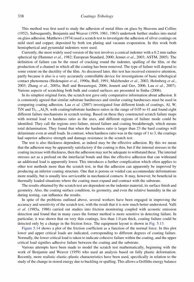
This method was first used to study the adhesion of metal films on glass by Heavens and Collins(1952). Subsequently, Benjamin and Weaver (1959, 1961, 1963) undertook further studies into metalon glass adhesion. Matthews (1974) used a scratch test to investigate the adhesion of silver coatings onmild steel and copper, deposited by both ion plating and vacuum evaporation. In this work bothhemispherical and pyramidal indenters were used.
Currently, the most widely used version of the test involves a conical indenter with a 0.2 mm radiusspherical tip (Hammer et al., 1982; European Standard, 2000; Jennet et al., 2003; ASTM, 2005). Thedefinition of failure can be the onset of cracking round the indenter, spalling of the film, or theproduction of a channel in which all the coating has been removed. The type of failure will depend tosome extent on the ductility of the film. As discussed later, this test has received extensive attention,partly because it also is a very accurately controllable device for investigations of basic tribologicalcontact phenomena (Hedenquist et al., 1990a; Bull, 1991; Malzbender et al., 2002; Holmberg et al.,2003; Zhang et al., 2005a; Bull and Berasetegui, 2006; Jennett and Gee, 2006; Lau et al., 2007).Various aspects of scratching both bulk and coated surfaces are presented in Sinha (2006).
In its simplest original form, the scratch test gave only comparative information about adhesion. Itis commonly agreed that similar substrate hardnesses and similar coating hardnesses must be used incomparing coating adhesion. Lau et al. (2007) investigated four different kinds of coatings, Al, W,TiN and Ti1�xAlxN, with coating/substrate hardness ratios in the range of 0.05 to 41 and found eightdifferent failure mechanisms in scratch testing. Based on these they constructed scratch failure mapswith normal load vs hardness ratio as the axes, and different regions of failure mode could beidentified. They call the regions zero failure, mixed failure and coating breakthrough, which meanstotal delamination. They found that when the hardness ratio is larger than 23 the hard coatings willdelaminate even at small loads. In contrast, when hardness ratio was in the range of 1 to 3, the coatingshad superior adhesive strength and damage resistance in the scratch test.
The test is also thickness dependent, as indeed may be the effective adhesion. By this we meanthat the adhesion may be apparently satisfactory if the coating is thin, but if the internal stresses in thecoating increase with thickness, then the adhesion may not be adequate to withstand these. The internalstresses act as a preload on the interfacial bonds and thus the effective adhesion that can withstandan additional load is apparently lower. This introduces a further complication which often applies toother test methods more than the scratch test, in that the adhesion can apparently be improved byproducing an inferior coating structure. One that is porous or voided can accommodate deformationsmore readily, but is usually less serviceable in mechanical contacts. It may, however, be beneficial inthermally loaded situations where the coating must expand and contract with the substrate.
The results obtained by the scratch test are dependent on the indenter material, its surface finish andgeometry. Also, the coating surface condition, its geometry, and even the relative humidity in the airduring testing, can influence the results.
In spite of the problems outlined above, several workers have been engaged in improving theaccuracy and sensitivity of the scratch test, with the result that it is now much better understood. Valliet al. (1985a, 1986) carried out studies into friction monitoring coupled with acoustic emissiondetection and found that in many cases the former method is more sensitive in detecting failure. Inparticular, it was shown that on very thin coatings, less than 1.0 mm thick, coating failure could bedetected only by a change in the friction force. The equipment layout is shown in Fig. 5.13.
Figure 5.14 shows a plot of the friction coefficient as a function of the normal force. In this plotlower and upper critical loads are indicated, corresponding to different degrees of coating failure.Normally, the lower critical load is taken to indicate cohesive failure within the coating, and the uppercritical load signifies adhesive failure between the coating and the substrate.
Various attempts have been made to model the scratch test mathematically, beginning with thework of Benjamin and Weaver (1959) who used an analysis based on fully plastic deformation.Recently, more realistic elastic–plastic characteristics have been used, specifically in relation to thestudy of the change in stored energy due to buckling or spalling. This allows a Griffiths energy balance
338 Coatings Tribology
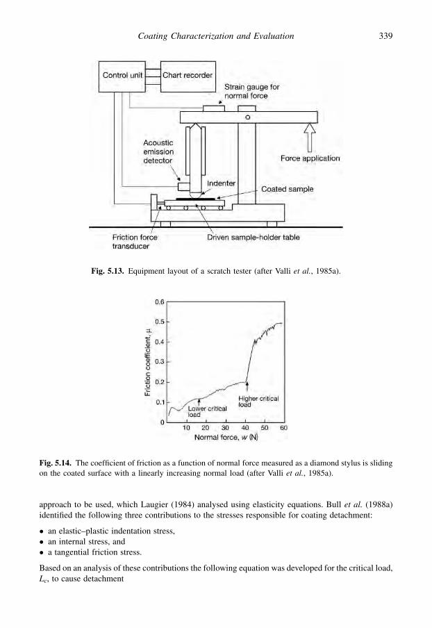
approach to be used, which Laugier (1984) analysed using elasticity equations. Bull et al. (1988a)identified the following three contributions to the stresses responsible for coating detachment:
� an elastic–plastic indentation stress,� an internal stress, and� a tangential friction stress.
Based on an analysis of these contributions the following equation was developed for the critical load,Lc, to cause detachment
Fig. 5.14. The coefficient of friction as a function of normal force measured as a diamond stylus is slidingon the coated surface with a linearly increasing normal load (after Valli et al., 1985a).
Fig. 5.13. Equipment layout of a scratch tester (after Valli et al., 1985a).
339Coating Characterization and Evaluation
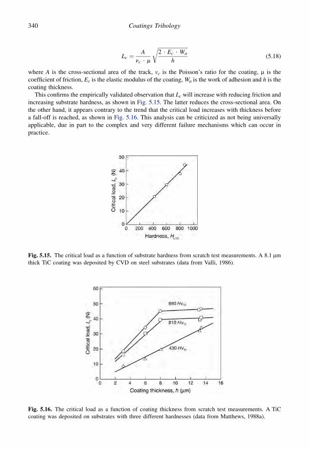
Lc ¼A
nc $ m
ffiffiffiffiffiffiffiffiffiffiffiffiffiffiffiffiffiffiffiffiffiffiffi2 $ Ec $ Wa
h
r(5.18)
where A is the cross-sectional area of the track, vc is the Poisson’s ratio for the coating, m is thecoefficient of friction, Ec is the elastic modulus of the coating, Wa is the work of adhesion and h is thecoating thickness.
This confirms the empirically validated observation that Lc will increase with reducing friction andincreasing substrate hardness, as shown in Fig. 5.15. The latter reduces the cross-sectional area. Onthe other hand, it appears contrary to the trend that the critical load increases with thickness beforea fall-off is reached, as shown in Fig. 5.16. This analysis can be criticized as not being universallyapplicable, due in part to the complex and very different failure mechanisms which can occur inpractice.
Fig. 5.15. The critical load as a function of substrate hardness from scratch test measurements. A 8.1 mmthick TiC coating was deposited by CVD on steel substrates (data from Valli, 1986).
Fig. 5.16. The critical load as a function of coating thickness from scratch test measurements. A TiCcoating was deposited on substrates with three different hardnesses (data from Matthews, 1988a).
340 Coatings Tribology
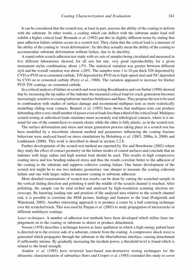
It can be considered that the scratch test, at least in part, assesses the ability of the coating to deformwith the substrate. In other words, a coating which can deflect with the substrate under load willexhibit a higher critical load. Bromark et al. (1992) put this in slightly different terms by stating thatpure adhesion failure seldom occurs in a scratch test. They claim that the critical load is a measure ofthe ability of the coating to ‘resist deformation’; by this they actually mean the ability of the coating toaccommodate substrate deformation without failure, due to its ductility.
A round-robin scratch adhesion test study with six sets of samples being circulated and measured infive different laboratories showed, for all sets but one, very good reproducibility for a giveninstrument–stylus combination, about �5%. The statistical variation was greater between differentstyli and the overall variation was about �20%. The samples were 1 to 10 mm thick TiN deposited byCVD or PVD on to cemented carbide, TiN deposited by PVD on to high-speed steel and TiC depositedby CVD on to cemented carbide (Perry et al., 1988). The variation appeared to increase for thickerPVD TiN coatings on cemented carbide.
In a critical analysis of failure in scratch and wear testing Rezakhanlou and von Stebut (1990) showedthat by increasing the tip radius of the indenter the measured critical load for crack generation becomesincreasingly sensitive to coating/substrate interface brittleness and flaws. They propose the test to be usedin combination with studies of surface damage and recommend multipass tests as more realisticallymodelling sliding wear contacts. Bennett et al. (1992) have shown that multipass tests can producedebonding after a very small number of passes even at loads less than a third of the critical load. Multipassscratch testing at subcritical loads simulates more accurately real tribological contacts, where it is un-usual for one of the counterfaces to remain elastic while the other is fully plastic, as in the scratch test.
The surface deformation and stress and strain generation process taking place in a scratch test hasbeen modelled by a microfinite element method and parameters influencing the coating fracturebehaviour were analysed based on stress simulations by Holmberg et al. (2003, 2006a, b, 2008) andLaukkanen (2006). This work is described in detail in section 3.2.8.
Further developments of the scratch test method are reported by Xie and Hawthorne (2002) wherethey study the effect of contact geometry on the failure modes of coated surfaces and conclude that anindenter with large radius and high normal load should be used. This results in high compressivecoating stress and low bending-induced stress and thus the results correlate better to the adhesion ofthe coating to the substrate and suppress cohesive coating failure. One future development of thescratch test might be to use two indenter geometries: one sharper to measure the coating cohesionfailure and one with larger radius to measure coating to substrate adhesion.
More detailed examinations of scratch test results can be done by cutting the scratched sample inthe vertical sliding direction and polishing it until the middle of the scratch channel is reached. Afterpolishing, the sample can be nital etched and analysed by high-resolution scanning electron mi-croscopy. By knowing loading rate and position of the analysed area relative to the scratch channelend, it is possible to correlate the SEM picture, findings and features to the load (Podgornik andWanstrand, 2005). Another interesting approach is to produce a crater by a ball cratering techniqueover the scratched track. This was used by Panjan et al. (2003) to study propagation of microcracks indifferent multilayer coatings.
Laser techniques. A number of adhesion test methods have been developed which utilize laser im-pingement on to the coating or substrate to detect or produce detachment.
Vossen (1978) describes a technique known as laser spallation in which a high-energy pulsed laseris directed on to the reverse side of a substrate, remote from the coating. A compressive shock wave isgenerated which propagates through the substrate to the film/substrate interface, causing detachmentif sufficiently intense. By gradually increasing the incident power, a threshold level is found which isrelated to the bond strength.
Aindow et al. (1985) have reviewed laser-based non-destructive testing techniques for theultrasonic characterization of subsurface flaws and Cooper et al. (1985) extended this study to cover
341Coating Characterization and Evaluation
the detection of laminar defects such as debonded regions. They apply a laser pulse on the coatingsurface, and detect the resultant acoustic waveform on the reverse side of the substrate. Satisfactoryimages of adhesion defects as small as 0.2 mm in width have been obtained. The coating thicknesswas about 0.5 mm, and the substrate was about 3.0 mm thick.
There have been attempts to permit the laser photoacoustic examination of coatings usinga transducer on the same side of the coating as the laser beam. This removes substrate thicknesslimitations and is intended to allow thinner coatings to be studied also. By using an appropriatemodulation frequency and a photoacoustic signal detector, films less than 2.0 mm in thickness havebeen successfully investigated. It could be argued that laser-based techniques of this type offer ad-vantages over other available methods. They are effectively non-destructive on well-adhered coatings.Also, by imposing a thermal gradient at the interface, they more accurately simulate many real op-erating conditions for coatings such as those in metal cutting.
Body-force methods. The adhesion of thin films can be assessed by imparting acceleration or de-celeration forces into the coating, as in ultra-centrifugal and ultrasonic methods (Valli et al., 1986),though these do not appear to have found widespread adoption. Some producers have adopted thenon-quantitative method of immersing coated objects in an ultrasonic cleaning bath to detect pooradhesion.
Acoustic imaging. It has been found that if a coating is observed in an acoustic microscope and also inan optical microscope, then the images produced can be compared and regions of poor adhesion canbe seen in the acoustic image. The acoustic microscope operates by applying a short radio frequencypulse to a piezoelectric transducer, producing an acoustic plane wave which is focused by a lens andcoupled to the reflecting object. The reflected pulse of sound returns through the lens to the transducer,which reconverts it to an electrical signal. By scanning the object mechanically a micrograph of thesurface can be obtained on a CRT screen. This method does not provide quantitative information(Bray, 1980; Ollendorf et al., 2001).
5.3.4 Physico-chemical evaluation
The developments in coating processes have been paralleled by improvements in the range andcapabilities of techniques for surface analysis. These are important to the tribologist not only sincethey permit identification and optimization of new coatings but also because they allow an improvedunderstanding of friction, wear and corrosion behaviour. Physico-chemical analysis techniques usedin combination with mechanical characterization are the key to future models which correlateproduction parameters, structure and material properties to achieve optimized performance.
There are many books and articles that focus especially on the subject of surface analysis, such asFerrante (1982), Chalker (1991), Vickerman (1997), Riviere and Myhra (1998), Briggs and Grant(2003), Flewitt et al. (2003), Werner (2003), Adams et al. (2005) and Birkholz et al. (2006). Here weshall confine ourselves to an overview of the subject.
Ferrante (1982) takes as a starting point the notion that almost all of the available methods utilizethe following process cycle:
Excitation (Interaction)↓
Dispersion↓
Detection↓
Spectrogram
342 Coatings Tribology
The first step involves the production of the particles of the material to be analysed, for example inphoton emission spectroscopy a spark may produce photons. Alternatively, the particle analysed couldbe an atom or cluster of atoms obtained by sputtering. The dispersion stage represents the mechanismby which the required information is filtered out from the available data. In light spectroscopy, thiscould be represented by a grating or prism; for an ion or electron it could be an electrostatic analyser.Next comes the detection stage, which could be a photographic plate for light or an electron multiplierfor ions or electrons. Finally, spectrograms can provide information about the chemistry (qualitative,quantitative and chemical state), morphology and microstructure.
It is common to categorize the various methods in a matrix form similar to that in Table 5.1. Thistable includes incident species in the left-hand column and emitted species along the top row andextends on an earlier table due to Chalker (1991).
The basic methods of surface analysis used for coatings are SEM, TEM, XRD, AES, XPS (ESCA),RBS and SIMS. The features of methods commonly used in tribology are shown in Tables 5.2 and 5.3.
AES has been used extensively to measure elemental compositions as a function of depth. In thatcase it is usual to prepare a section through the coating. The ball cratering method described earlierprovides a very convenient means of producing a tapered section. An alternative is in situ inert ionsputtering, with spectra being recorded after sequential etch cycles.
Both AES and XPS/ESCA are suitable techniques for elemental analysis. Sputter depth profilingand composition depth profiling are possible for both techniques (Quaeyhaegens et al., 1992; Bishop,1989; Christie, 1989). Chemical state information can be achieved by XPS/ESCA, in some cases alsowith AES (Bishop, 1989). In terms of the elemental analysis AES provides the complementaryinformation to X-ray microanalysis (EDX).
SIMS examines charged particles sputtered from a surface and is used in tribology extensively toanalyse the composition of thin surface transfer and reaction films. SIMS provides good data aboutvery thin surface films but there is also a large averaging effect. The data are based on an area ofnormally more than 1 mm in diameter of the surface and cannot show the variations in thecomposition within this area that in tribological films may be significant (Stachowiack et al., 2004).
X-ray diffraction (XRD) is one of the most widely used techniques in surface engineering. It has thepotential to provide a very diverse range of information, such as phase composition, grain size,residual strain/stress and texture/grain orientation. Chalker (1991) provides a useful overview on theinterpretation of XRD data.
The third generation coatings are mostly multiply layered or multiply treated. Depth resolution istherefore of fundamental importance. The so-called low angle diffraction (LAD) technique can beused to achieve depth-related information simply by altering the angle of incidence, and therefore thepenetration depth (Schneider, 1994). This can be done using a regular Bragg–Brentano diffractometerwith a suitable hardware configuration on the secondary side: usually a long collimator, for angularresolution, and a monochromator, permitting discrimination in favour of the source Ka line. The LADtechnique is not only of interest for layered or multiply treated samples, it is also of great potential indetecting compositional and microstructural gradients as a function of depth in a single layer. Forexample, Schneider (1994) has identified strain and phase gradients in plasma-nitrided stainless steels.
Other useful tools are the scanning and transmission electron microscopes. The former is usedroutinely for observing fracture and polished sections of coatings, permitting characterization of themorphology. Energy dispersive X-ray analysis (EDX) and wavelength dispersive X-ray analysis(WDX) can be used for elemental composition analysis, with suitable calibration. The transmissionelectron microscope (TEM) is in increasing use to study coating grain structures, and specifically toprovide hitherto unobtainable information about interfacial effects including heteroepitaxial growththrough the technique of cross-sectional TEM (Hakansson et al., 1991).
New coatings, such as diamond and diamond-like carbon have led to the further development ofmethods such as Fourier transform infra-red spectroscopy (FTIR) and Raman spectroscopy to provideinformation unobtainable by other techniques. FTIR utilizes the mechanism that photons with a range
343Coating Characterization and Evaluation

Table 5.1. Classification of analytical techniques in terms of the incident excitation source and analysed emission.
Emitted incident Optical (photons) X-rays Electrons Ions
Optical (photons) IR, VIS, UV, PL, EL UPSX-rays XRF, XRD ESCA, XAES, ESD, XPS, EXAFS ESDElectrons EMPA, EDX LEED, EELS, TEM, SEM, AES, SAMIons PIXE IAES SIMS, RBS, NRA, ERDA, NIMS
AES: Auger electron spectroscopy PIXE: particle-induced X-ray emissionEDX: energy dispersive X-ray analysis PL: photoluminescenceEELS: electron energy loss spectroscopy RBS: Rutherford backscattering spectroscopyEL: ellipsometry SAM: scanning Auger microscopyEMPA: electron microprobe analysis SEM: scanning electron microscopyERDA: elastic recoil detection analysis SIMS: secondary ion mass spectrometryESCA: electron spectroscopy for chemical analysis TEM: transmission electron microscopyESD: electron stimulated desorption UPS: ultraviolet photoelectron spectroscopyEXAFS: extended X-ray absorption fine structure UV: ultraviolet spectroscopyIAES: ion-induced Auger electron spectroscopy VIS: visible spectroscopyIR: infrared spectroscopy XAES: X-ray induced AESLEED: low-energy electron diffraction XPS: X-ray photoelectron spectroscopyNIMS: neutral ion mass spectroscopy XRD: X-ray diffraction analysisNRA: nuclear reaction analysis XRF: X-ray fluorescence
34
4C
oa
ting
sT
ribo
log
y

Table 5.2. Evaluation of surface analytical tools (after Ferrante, 1982).
Surfacesensitive
Commerciallyavailable
Analysis ofpractical systems
Elementalanalysis
Compoundanalysis
Analysisquantitative
1. Elemental and chemical results by electron levelsAESESCA-XPSUPSEMPAXRF
YesYesYesNoNo
YesYesYesYesYes
YesYesNoYesYes
YesYesNoYesYes
To a degreeYesNoNoNo
To a degreeYesNoYesYes
2. Chemical and elemental analysis by massRBSSIMS
NoYes
YesYes
YesYes
YesYes
NoTo a degree
YesTo a degree
3. Elemental analysis by vibrational stateEELS Yes Yes No No No No
4. Structural analysis, macroscopic featuresSEMEL
YesYes
YesYes
YesYes
Yes with EDXNo
To a degreeNo
To a degreeNo
5. Structural analysis microscopicEXAFSLEED
YesYes
NoYes
YesNo
NoNo
NoNo
NoNo
34
5C
oa
ting
Ch
ara
cterizatio
na
nd
Eva
lua
tion
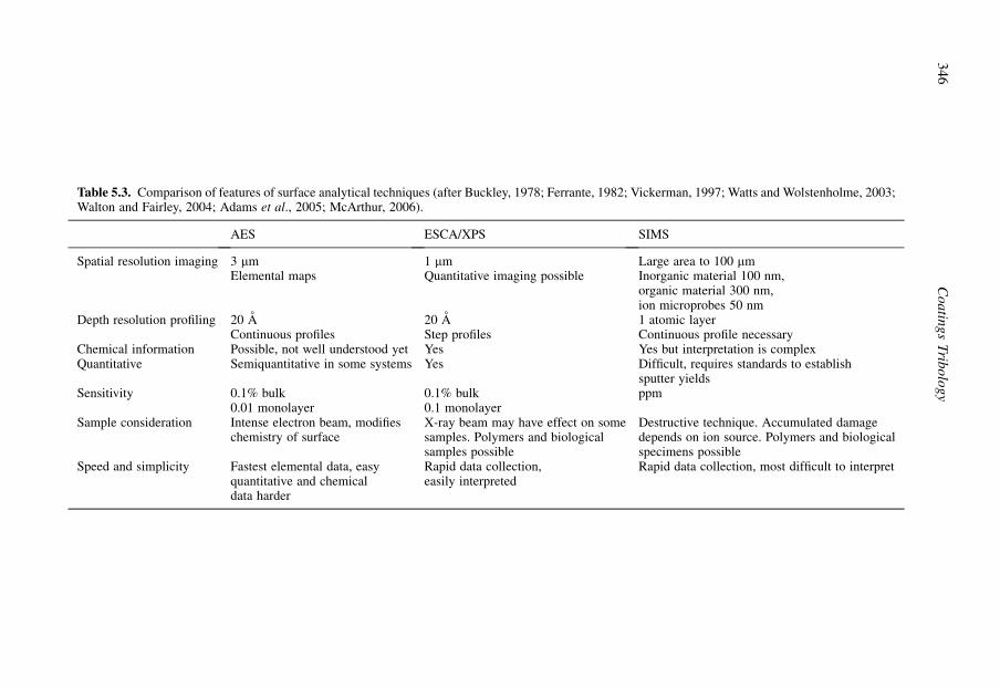
Table 5.3. Comparison of features of surface analytical techniques (after Buckley, 1978; Ferrante, 1982; Vickerman, 1997; Watts and Wolstenholme, 2003;Walton and Fairley, 2004; Adams et al., 2005; McArthur, 2006).
AES ESCA/XPS SIMS
Spatial resolution imaging 3 mmElemental maps
1 mmQuantitative imaging possible
Large area to 100 mmInorganic material 100 nm,organic material 300 nm,ion microprobes 50 nm
Depth resolution profiling 20 AContinuous profiles
20 AStep profiles
1 atomic layerContinuous profile necessary
Chemical information Possible, not well understood yet Yes Yes but interpretation is complexQuantitative Semiquantitative in some systems Yes Difficult, requires standards to establish
sputter yieldsSensitivity 0.1% bulk
0.01 monolayer0.1% bulk0.1 monolayer
ppm
Sample consideration Intense electron beam, modifieschemistry of surface
X-ray beam may have effect on somesamples. Polymers and biologicalsamples possible
Destructive technique. Accumulated damagedepends on ion source. Polymers and biologicalspecimens possible
Speed and simplicity Fastest elemental data, easyquantitative and chemicaldata harder
Rapid data collection,easily interpreted
Rapid data collection, most difficult to interpret
34
6C
oa
ting
sT
ribo
log
y

of frequencies can be absorbed by chemical bonds with corresponding frequencies, and this allows thestudy of, for example, C–H bonds. Raman spectroscopy utilizes the inelastic scattering of photons bymolecules to provide chemical structure information (Blanpain et al., 1992).
However, none of the techniques mentioned above is able to solve all problems in characterizingcoatings. It is therefore usually necessary to utilize several different techniques in order to fullycharacterize a surface or coating.
5.3.5 Tribological evaluation
Throughout this book we refer to different tribological tests which are in use in various laboratories. Asis typical for tribology, even today there are a very wide variety of such tests with little standardization.
Some typical configurations are shown in Table 5.4 partly adapted and further modified fromHMSO (1986). Tribological test methods and equipment are also presented in an ASTM book (Bayer,1982) devoted to the subject of wear tests for coatings and by Bhushan and Gupta (1991), Czichos andHabig (1992), Bhushan (1999b), Spikes (1999), Szczerek et al. (2001), Hogmark et al. (2001), Blau(2001) and Hsu et al. (2005).
5.3.5.1 Sliding tests
The variety of tribological test methods used only for sliding contacts is illustrated by Bhushan andGupta (1991) who list details of eight test methods. Of these, the pin-on-disk test is very suitable asa material screening test and for friction and wear mechanism analysis. It is by far the most widelyused. Indeed, it was the subject of an international interlaboratory exercise aimed at standardization,under the auspices of VAMAS (Versailles Project on Advanced Materials and Standards). The lessonslearned from this exercise have been published by Czichos et al. (1987, 1989) and used as the basis foran ASTM wear testing standard (G-99) and a DIN standard (DIN 50324). The other test methods maybe very useful in cases where they better simulate the actual contact conditions and the results thusbecome easier to transfer to a specific application.
A typical pin-on-disk layout complete with humidity and temperature control, which is importantin dry sliding experiments, is shown in Fig. 5.17. In the authors’ laboratories a spherically ended pin(conveniently an AISI 52100 hardened ball, 10 mm in diameter) contacts a coated disk. The slidingconditions are typically a 10 N normal force and a sliding speed of 0.1 m/s in an environment of 50%RH, according to the VAMAS specifications. A total sliding distance of 100 to 1000 m is typical fortests with coated samples. The wear is assessed by stylus profilometry of the wear track and by directmicroscopic observation.
As part of the round-robin study referred to in section 5.3.2, the authors carried out pin-on-disk testson the three coatings, under the unlubricated conditions referred to, for a sliding distance of 250 m.The pin material in this case was M50 steel hardened to 62 Rc. The relative humidity at laboratoriesdesignated UH and VTT was 50%� 2%, and at THD it was 68%� 4%. The temperature for the VTTand UH tests was 21� 2�C, while at THD it was 23� 1�C. THD also had a vertical disk orientation,whereas the others used a horizontal disk.
The results, given in Fig. 5.18, show that even if the repeatability of the tests may be good withineach laboratory, there can be a large variation in the reproducibility from one laboratory to another.
Engineers frequently tend to regard the friction coefficient, like hardness, as a kind of intrinsicmaterial property. This is, however, not the case, since both are the result of quite complex interactivebehaviour, and are subject to statistical variability. A measured friction coefficient is the result of bothphysical and chemical interaction in a discrete system, which is quite difficult to repeat from onelaboratory to another because of the large number of influencing parameters. In the case of pin-on-disktesting it has been observed that even the vibrational characteristics of the test machine can havea marked influence on friction and wear behaviour. The level of reproducibility reported here is quitetypical and has also been found in tests on bulk materials, as shown in Fig. 5.19.
347Coating Characterization and Evaluation

Table 5.4. Wear and friction test methods for tribological evaluation of coated surfaces. Typicalparameters are given but many variations of these are in use.
Pin-on-flat (ASTM) Pin-on-disk (VAMAS) Block-on-ring (ASTM)
Testconfiguration
Test purpose Determination of wear rate andcoefficient of friction at lowloads and speeds and with smallspecimens.
Determination of slidingwear rate and coefficient offriction.
Determination of adhesivewear rate of materials.
Specimens A pin or a ball rubbing againsta plate.
A pin or a ball rubbing ona rotating plate.
A steel ring is rotated againsta stationary block.
Testconditions (typical)
Reciprocating sliding frequency5 Hz.Stroke length 10 mm. Load25 N. Temperature 18–23�C.Humidity40–60% RH. Specimen can bedry or fully immersed inlubricant.
Sliding speed 0.1 m/s. Load10 N.Sliding distance 1 km.Temperature 23�C.Humidity 50% RH.
Ring speed (max) 7000 rev/min.Load (max) 6000 N.Duration 5400–24,000cycles.Specimen can be dry orimmersed in oil or otherfluid.
Measurements Weight loss of disk.Height loss of pin.Wear track profilometry.Ball wear area measurement.Friction force.
Height loss of pin. Weartrack profilometry.Ball wear area measurement.Friction force.
Test block weight loss. Scarwidth.Ring weight loss. Frictionforce.Lubricant film load-carryingcapacity.
Wear types/comments Mild adhesive wear suitable fortribological coating evaluation.
Mild and severe adhesivewear. Suitable fortribological coatingevaluation.
Mild and severe adhesivewear. Lubricated wear.
Block-on-pin (Falex) Twin disc (Amsler)
Testconfiguration
Test purpose Determination of wear rate, load-carryingcapacity and friction coefficient for slidingcontacts.
Determination of sliding or rolling wear rateof test materials, treatments or coatings.
Specimens A 6.35 mm diameter cylindrical journal isrotated within two loaded stationary V-blocks togive a4-line contact.
Normally, two disks 40 mm diameter and10 mm thick. Alternatively, the disks may be30 and 50 mm in diameter.
Test conditions Journal speed 290 rev/min.Sliding velocity 0.1 m/s. Load (constant orincreasing) 89–20,000 N.Hertz stress 242–3450 MN/m2.Specimens can be immersed in oil or other fluid.
Lower disk speed 0–400 rev/min.Upper disk speed 440 rev/min.Load 200–2000 N.Dry or lubricated.
Measurements Journal driving torque. Progressing wear depth.Wear life. Seizure failure load.Final specimen weights.
Individual disk weight loss or profile.Total disk weight loss.Wear life.
Wear types/ comments Mild and severe adhesive wear. Scuffing. Mild and severe adhesive wear. Rollingcontact fatigue (pitting).
348 Coatings Tribology

Hammer wear Fretting Rubber wheel abrasion(ASTM)
Testconfiguration
Test purpose Determination of cohesionand adhesion qualities ofcoatings and also theirwear characteristicsunder arduous vibratingconditions.
Determination of wear rateand friction in smallamplitude oscillatingcontacts.
Determination of wearresistance of materials tothird body-scratchingabrasion.
Specimens Obliquely cut specimens of23 mm2 contact area.
Ball or pin against a flatplate.
Flat (coated) pad is loadedagainst a rotating rubberwheel. The abrasive particlesare a rounded quartz grain sandas typified.
Testconditions
Combined impact andsliding.Sliding distance 0.76 mm.Impact frequency60–70 Hz.Impact load 60–223 N.Temperature 600�C.Duration 6–10 h.
Sliding amplitude0.02–0.4 mm.Sliding frequency5–20 Hz.Load 2–50 N. Temperature22�C. Specimen can bedry or fully immersed inlubricant.
Wheel speed 2000 rev/min.Load 130 N.The abrasive media is drysand particles or sandparticles in wet slurry.
Measurements Volume loss.Fretting resistance.
Volume loss by wear scarmeasurements. Frictionforce.
Weight lossor wear scardepth by profilometry.
Wear types/comments Adhesive wear.Fatigue wear. Fretting.
Fretting wear. Dry or wet low stressabrasion.
Dry abrasion (Taber) Wet slurry abrasion
Testconfiguration
Test purpose Determination of the abrasive wearrate and the Taber wear index ofmaterial surfaces.
Determination of the abrasive wearrate and the abrasion resistance ofmaterials and treatments.
Specimens Flat face of the disk abraded by tworubber bonded abrasive wheels (CS-10).
Two specimen pads loaded againsta rotating circular plate.
Test conditions Load 9.81 N.Wheels cleaned with abrasive paperevery 1000 revolutions.Test is run without lubricant.
Load 112 N.Runs in bath of abrasive slurry.
Measurements Weight loss.Taber wear index¼weight loss/1000revs (mg).
Volume loss.
Wear types/ comments Low stress abrasion. High stress grinding abrasion. Lowstress abrasion.
Table 5.4. Continued
349Coating Characterization and Evaluation

Fig. 5.17. Equipment layout for a pin-on-disk tester with humidity and temperature control.
Fig. 5.18. Friction coefficients of a steel pin against coated surfaces measured by pin-on-disk testers inthree different laboratories at a sliding speed of 0.1 m/s and a load of 10 N (data from Ronkainen et al.,1990b).
350 Coatings Tribology
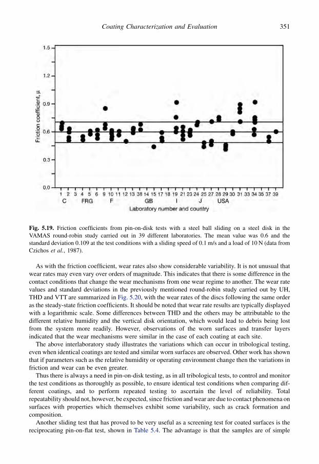
As with the friction coefficient, wear rates also show considerable variability. It is not unusual thatwear rates may even vary over orders of magnitude. This indicates that there is some difference in thecontact conditions that change the wear mechanisms from one wear regime to another. The wear ratevalues and standard deviations in the previously mentioned round-robin study carried out by UH,THD and VTT are summarized in Fig. 5.20, with the wear rates of the discs following the same orderas the steady-state friction coefficients. It should be noted that wear rate results are typically displayedwith a logarithmic scale. Some differences between THD and the others may be attributable to thedifferent relative humidity and the vertical disk orientation, which would lead to debris being lostfrom the system more readily. However, observations of the worn surfaces and transfer layersindicated that the wear mechanisms were similar in the case of each coating at each site.
The above interlaboratory study illustrates the variations which can occur in tribological testing,even when identical coatings are tested and similar worn surfaces are observed. Other work has shownthat if parameters such as the relative humidity or operating environment change then the variations infriction and wear can be even greater.
Thus there is always a need in pin-on-disk testing, as in all tribological tests, to control and monitorthe test conditions as thoroughly as possible, to ensure identical test conditions when comparing dif-ferent coatings, and to perform repeated testing to ascertain the level of reliability. Totalrepeatability should not, however, be expected, since friction and wear are due to contact phenomena onsurfaces with properties which themselves exhibit some variability, such as crack formation andcomposition.
Another sliding test that has proved to be very useful as a screening test for coated surfaces is thereciprocating pin-on-flat test, shown in Table 5.4. The advantage is that the samples are of simple
Fig. 5.19. Friction coefficients from pin-on-disk tests with a steel ball sliding on a steel disk in theVAMAS round-robin study carried out in 39 different laboratories. The mean value was 0.6 and thestandard deviation 0.109 at the test conditions with a sliding speed of 0.1 m/s and a load of 10 N (data fromCzichos et al., 1987).
351Coating Characterization and Evaluation

geometry and the test dynamics is well controlled. If the test is used with small sliding amplitude thecontact mechanism will be fretting wear. The fretting test has been developed to be almost a tri-bological reference test (Klafke, 2004b) and fretting maps are available (Zhou et al., 2006).
A new range of requirements for tribotesting is coming from the development of microdevices re-lated to nanotechnology research and development, such as micro-electro-mechanical-systems(MEMS). In such devices the loads are typically in the milli-newton range, the wear depth in thenanometre range and the dissipated energy in the microjoule range. Reciprocating sliding contacttribotesting devices have been developed to meet these requirements both on a micro- and nanolevel(Achanta et al., 2005).
5.3.5.2 Abrasion testing
The best known tests in this category are the Taber test and the rubber wheel test, shown in Table 5.4and Fig. 5.21. The former relies on the abrasiveness of the rotating wheels, while the latter utilizes
Fig. 5.20. Wear rates of coated surfaces measured by pin-on-disk tests in three different laboratories ata sliding speed of 0.1 m/s and a load of 10 N (data from Ronkainen et al., 1990b).
352 Coatings Tribology
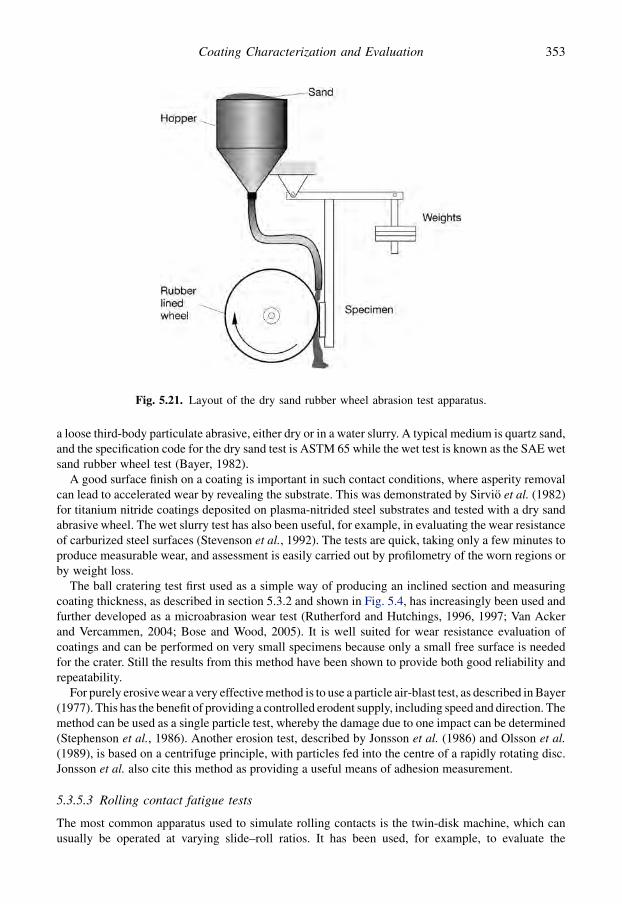
a loose third-body particulate abrasive, either dry or in a water slurry. A typical medium is quartz sand,and the specification code for the dry sand test is ASTM 65 while the wet test is known as the SAE wetsand rubber wheel test (Bayer, 1982).
A good surface finish on a coating is important in such contact conditions, where asperity removalcan lead to accelerated wear by revealing the substrate. This was demonstrated by Sirvio et al. (1982)for titanium nitride coatings deposited on plasma-nitrided steel substrates and tested with a dry sandabrasive wheel. The wet slurry test has also been useful, for example, in evaluating the wear resistanceof carburized steel surfaces (Stevenson et al., 1992). The tests are quick, taking only a few minutes toproduce measurable wear, and assessment is easily carried out by profilometry of the worn regions orby weight loss.
The ball cratering test first used as a simple way of producing an inclined section and measuringcoating thickness, as described in section 5.3.2 and shown in Fig. 5.4, has increasingly been used andfurther developed as a microabrasion wear test (Rutherford and Hutchings, 1996, 1997; Van Ackerand Vercammen, 2004; Bose and Wood, 2005). It is well suited for wear resistance evaluation ofcoatings and can be performed on very small specimens because only a small free surface is neededfor the crater. Still the results from this method have been shown to provide both good reliability andrepeatability.
For purely erosive wear a very effective method is to use a particle air-blast test, as described in Bayer(1977). This has the benefit of providing a controlled erodent supply, including speed and direction. Themethod can be used as a single particle test, whereby the damage due to one impact can be determined(Stephenson et al., 1986). Another erosion test, described by Jonsson et al. (1986) and Olsson et al.(1989), is based on a centrifuge principle, with particles fed into the centre of a rapidly rotating disc.Jonsson et al. also cite this method as providing a useful means of adhesion measurement.
5.3.5.3 Rolling contact fatigue tests
The most common apparatus used to simulate rolling contacts is the twin-disk machine, which canusually be operated at varying slide–roll ratios. It has been used, for example, to evaluate the
Fig. 5.21. Layout of the dry sand rubber wheel abrasion test apparatus.
353Coating Characterization and Evaluation

performance of carburized surfaces for gears (Nieminen, 1990). Other rolling contact tests are usedfor evaluating lubricants and the high cycle fatigue behaviour of ball bearings. The resistance to cyclicloading can also be determined without rolling by applying a dynamic impact load on a coated sample(Knotek et al., 1992a). This also provides an effective test of coating adhesion.
As mentioned in Chapters 4 and 7, rolling contact conditions are not the traditional domain ofcoatings. However, there is increasing evidence that very thin PVD coatings can enhance bearing andgear life under rolling contact fatigue conditions even if conflicting results have also been reported(Chang et al., 1990; Amaro et al., 2005; Yonekura et al., 2005).
5.3.5.4 Laboratory simulation tests
There are a number of examples of research which have simulated real operating conditions ina laboratory environment in an effective way.
Matthews (1980) and Matthews and Teer (1980) devised a multistroke plane–strain compression testto simulate a cold forging operation between two coated dies. The test was run for 5000 indentations instrip steel at 50% strain, and provided an excellent assessment both of coating adhesion and of theretention of hardness in the dies during coating. Industry often needs to have this kind of evidence ofcoating reliability before it will risk putting a new coating into its production facilities.
Another example of a test, designed to simulate a specific industrial contact condition, is bending-under-tension (Sundquist et al., 1983). This replicates a press forming operation and permits theevaluation of coatings for sheet press tools. As shown in Fig. 5.22, the method involves pulling stripmetal over a coated die and is a severe test of anti-galling, i.e. severe adhesive wear resistance of thecoating. This test was successfully used to show that it is possible to avoid the need for press forminglubricants by using hard PVD coatings.
Another common tribocontact in industry is the metal cutting tool to workpiece interface. This ismore difficult to simulate, because of the high contact forces and heat generated. Nevertheless,methods have been developed to evaluate coatings for these conditions (Hedenquist and Olsson, 1991;Hedenquist et al., 1990b; Habig and Meier zu Kocker, 1992).
Ultimately, the only truly satisfactory test is to run the coating under its intended operating conditions,and for metal cutting trials it is common to use the ISO 3685:1983 standard (Tool Life Testing with Single-Point Turning Tools). Ronkainen et al. (1991b) report the results of tests using this standard. For millingthe standards are ISO 8688-1:1989 and ISO8688-2:1989 (Tool Life Testing in Milling, Part 1: FaceMilling and Part 2: End Milling). For interrupted cutting conditions, in which there is a repeated impactaction on the coating Knotek et al. (1992d) have devised a coating impact test which allows quantificationof the number of impacts which a coating can withstand and the definition of a critical fatigue force.
There have been a large number of tribological tests reported of coated real products in laboratoryconditions, such as testing of coated gears by Amaro et al. (2005).
Very advanced laboratory testing of a high power clutch system was carried out by Watson et al.(2005) and their analysis and interpretation of results includes developing a dynamic clutch model,
Fig. 5.22. Tribological contact in the bending-under-tension test.
354 Coatings Tribology
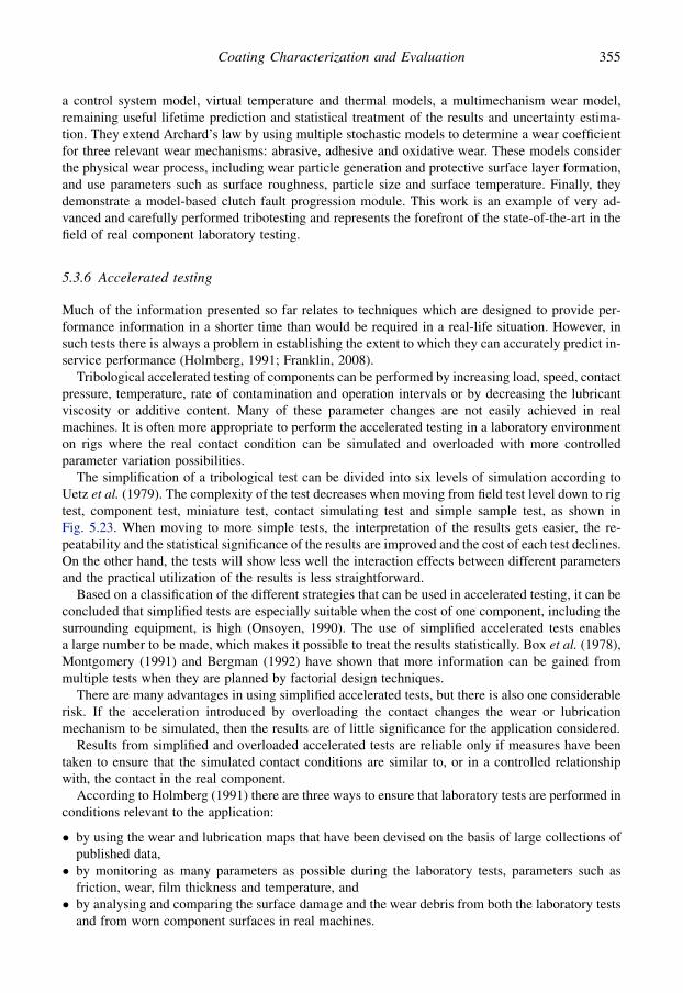
a control system model, virtual temperature and thermal models, a multimechanism wear model,remaining useful lifetime prediction and statistical treatment of the results and uncertainty estima-tion. They extend Archard’s law by using multiple stochastic models to determine a wear coefficientfor three relevant wear mechanisms: abrasive, adhesive and oxidative wear. These models considerthe physical wear process, including wear particle generation and protective surface layer formation,and use parameters such as surface roughness, particle size and surface temperature. Finally, theydemonstrate a model-based clutch fault progression module. This work is an example of very ad-vanced and carefully performed tribotesting and represents the forefront of the state-of-the-art in thefield of real component laboratory testing.
5.3.6 Accelerated testing
Much of the information presented so far relates to techniques which are designed to provide per-formance information in a shorter time than would be required in a real-life situation. However, insuch tests there is always a problem in establishing the extent to which they can accurately predict in-service performance (Holmberg, 1991; Franklin, 2008).
Tribological accelerated testing of components can be performed by increasing load, speed, contactpressure, temperature, rate of contamination and operation intervals or by decreasing the lubricantviscosity or additive content. Many of these parameter changes are not easily achieved in realmachines. It is often more appropriate to perform the accelerated testing in a laboratory environmenton rigs where the real contact condition can be simulated and overloaded with more controlledparameter variation possibilities.
The simplification of a tribological test can be divided into six levels of simulation according toUetz et al. (1979). The complexity of the test decreases when moving from field test level down to rigtest, component test, miniature test, contact simulating test and simple sample test, as shown inFig. 5.23. When moving to more simple tests, the interpretation of the results gets easier, the re-peatability and the statistical significance of the results are improved and the cost of each test declines.On the other hand, the tests will show less well the interaction effects between different parametersand the practical utilization of the results is less straightforward.
Based on a classification of the different strategies that can be used in accelerated testing, it can beconcluded that simplified tests are especially suitable when the cost of one component, including thesurrounding equipment, is high (Onsoyen, 1990). The use of simplified accelerated tests enablesa large number to be made, which makes it possible to treat the results statistically. Box et al. (1978),Montgomery (1991) and Bergman (1992) have shown that more information can be gained frommultiple tests when they are planned by factorial design techniques.
There are many advantages in using simplified accelerated tests, but there is also one considerablerisk. If the acceleration introduced by overloading the contact changes the wear or lubricationmechanism to be simulated, then the results are of little significance for the application considered.
Results from simplified and overloaded accelerated tests are reliable only if measures have beentaken to ensure that the simulated contact conditions are similar to, or in a controlled relationshipwith, the contact in the real component.
According to Holmberg (1991) there are three ways to ensure that laboratory tests are performed inconditions relevant to the application:
� by using the wear and lubrication maps that have been devised on the basis of large collections ofpublished data,� by monitoring as many parameters as possible during the laboratory tests, parameters such as
friction, wear, film thickness and temperature, and� by analysing and comparing the surface damage and the wear debris from both the laboratory tests
and from worn component surfaces in real machines.
355Coating Characterization and Evaluation
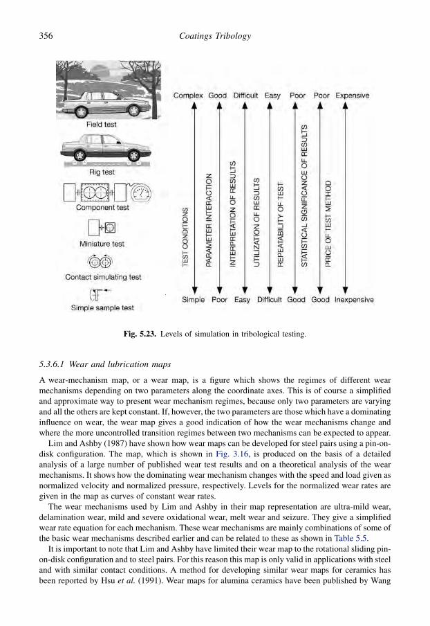
5.3.6.1 Wear and lubrication maps
A wear-mechanism map, or a wear map, is a figure which shows the regimes of different wearmechanisms depending on two parameters along the coordinate axes. This is of course a simplifiedand approximate way to present wear mechanism regimes, because only two parameters are varyingand all the others are kept constant. If, however, the two parameters are those which have a dominatinginfluence on wear, the wear map gives a good indication of how the wear mechanisms change andwhere the more uncontrolled transition regimes between two mechanisms can be expected to appear.
Lim and Ashby (1987) have shown how wear maps can be developed for steel pairs using a pin-on-disk configuration. The map, which is shown in Fig. 3.16, is produced on the basis of a detailedanalysis of a large number of published wear test results and on a theoretical analysis of the wearmechanisms. It shows how the dominating wear mechanism changes with the speed and load given asnormalized velocity and normalized pressure, respectively. Levels for the normalized wear rates aregiven in the map as curves of constant wear rates.
The wear mechanisms used by Lim and Ashby in their map representation are ultra-mild wear,delamination wear, mild and severe oxidational wear, melt wear and seizure. They give a simplifiedwear rate equation for each mechanism. These wear mechanisms are mainly combinations of some ofthe basic wear mechanisms described earlier and can be related to these as shown in Table 5.5.
It is important to note that Lim and Ashby have limited their wear map to the rotational sliding pin-on-disk configuration and to steel pairs. For this reason this map is only valid in applications with steeland with similar contact conditions. A method for developing similar wear maps for ceramics hasbeen reported by Hsu et al. (1991). Wear maps for alumina ceramics have been published by Wang
Fig. 5.23. Levels of simulation in tribological testing.
356 Coatings Tribology

et al. (1991). Vingsbo et al. (1990) have developed fretting maps to show the wear behaviour inreciprocating moving contacts. They use displacement amplitude and frequency or tangential forceamplitude and normal load as coordinate axes in their maps. Further development of frettingwear maps was done by Fouvry and Kapsa (2001) and Zhou et al. (2006). Wear maps for uncoatedhigh-speed steel cutting tools with feed rate and cutting speed as coordinate axes have been publishedby Lim et al. (1993a, b).
In a review paper of wear-mechanism maps Lim (1998) covers the development of wear mapsincluding maps for metals, ceramics, metal–matrix composites, polymers, coatings, tools, fretting,erosion and maps for time-dependent wear transitions. He sites wear maps especially for coatedsurfaces related to wear of abradable coatings on gas-turbine components and flank-wear as well ascrater-wear maps for TiN coated high-speed steel inserts. In a discussion on the tribological funda-mentals behind wear mapping Williams (2005) concludes that wear maps are useful as they enableimplications of wear on changes in design, material and operating parameters to be assessed and allowsensible correlation to be made between laboratory-based experimental investigations and observa-tions in the field.
Similarly, Begelinger and de Gee (1981) developed a kind of lubrication mechanism map to show thechanges from one lubrication regime to another. They represented the lubrication regimes as elasto-hydrodynamic (I), boundary (II) and scuffing (III) in a map with velocity and load as coordinate axes, asshown in Fig. 5.24. Scuffing is not really a lubrication mechanism but can be considered as a contactmechanism for failed lubrication. These lubrication maps are also known as IRG transition diagrams(IRG¼ International Research Group for Wear of Materials under the sponsorship of OECD).
Methods for construction of both wear and lubrication maps have been described in detail by Hsuand Shen (2005). They show how wear maps can be used as material selection guides and to supportwear modelling and wear prediction.
Wear and lubrication maps are very useful when performing an accelerated test. By comparing theactual test parameters to these maps, it is possible to identify what kind of contact mechanisms can beexpected and how close to the transition regions the test is, even if the map cannot be considered asexact. The accelerated test results are likely to be relevant to a real contact if they are both within thesame wear or lubrication regime.
5.3.6.2 Test parameter monitoring
It is possible to obtain an indication of the dominating lubrication or wear mechanism by monitoringsuitable test parameters such as friction, lubricant film thickness, temperature, wear and surfaceroughness. The advantage of parameter monitoring is that an indication of the contact mechanismsduring the whole process of wear is obtained and possible changes in the mechanisms and the timewhen they take place are identified.
Friction is measured in most accelerated tests. The coefficient of friction in lubricated contactsgives an indication of the lubrication regime, as shown in Fig. 5.24, but this information may not
Table 5.5. The wear mechanisms used in the Lim and Ashby (1987) wear maps are combinations ofbasic wear mechanisms.
Wear mechanisms Adhesion Abrasion Fatigue Chemical wear
Seizure X XMelt wear XSevere oxidational wear X XMild oxidational wear X XDelamination wear X XUltra-mild wear X
357Coating Characterization and Evaluation

be very accurate. Lim et al. (1989) have also shown that typical values for the coefficient of frictioncan be plotted on the wear map for dry steel contacts but this estimation may not be very accurateeither.
A better way to define the lubrication regime in a contact is to measure the film thickness. This canmost easily be achieved by passing an electrical current through the contact and measuring theelectrical resistance or the capacitance, to give information about the amount of metallic contact(Dowson and Whomes, 1967–68; Georges et al., 1983; Suzuki and Ludema, 1987). This gives a goodindication of the transition region between boundary and full film (HD and EHD) lubrication, but notan absolute value for the film thickness. An absolute value for the film thickness can be determined bymeasuring the capacitance between the two parts, but this technique and especially the calibration issomewhat more complicated (Schmidt, 1985; Alliston-Greiner et al., 1987). An alternative innovationis to use ultrasound (Dwyer-Joyce et al., 2002, 2004).
Accurate on-line wear measurements are difficult to perform. One approach is to measure the acousticemission signal from the tribological contact. The source of the signal is a rapid release of stored energycaused by cracking or crack propagation and thus this relates to the origin of wear debris generation (Lohret al., 2006). This is a very sensitive technique and if the sensor is not mounted properly and close enoughto the contact the signal is easily disturbed. Lohr et al. report very good wear monitoring results and intheir experiments the acoustic emission sensor was mounted 1 mm from the centre of the contact area.
Another approach is the radionuclide technique (RNT) where the samples are made radioactive andthen the amount of wear debris by radiation measurements is registered (Ivkovic and Lazic, 1975;Scherge et al., 2003b). The handling of the irradiated samples is not a problem since the radiationlevels used with the techniques are very small. This method has an extremely high resolution andaccuracy and is thus especially suited to mechanical systems showing very low wear rates; e.g.running-in wear in real combustion engines can be precisely assessed. Scherge et al. (2003b) presentthe modern RNT and conclude that this technique is very useful for continuous measurement anddisplay of wear as a function of time on machine parts in operation as well as simultaneous
Fig. 5.24. Lubrication map showing (I) elastohydrodynamic, (II) boundary and (III) scuffing lubricationregimes for sliding concentrated steel contacts operating fully submerged in a liquid lubricant. K is thewear rate (10�6 mm3/Nm) and m the friction coefficient (data from Begelinger and de Gee, 1981).
358 Coatings Tribology

measurement of wear for different selected machine parts or different locations on the same machinepart. The high sensitivity is capable of resolving wear rates as low as 0.01 nm/h or 1 mg/h.
Wear particle analysis of oil samples from the contact by the ferrography method is a well-established technique which gives a good indication of changes in the wear mechanism or the wearrate (Jones et al., 1978; Lansdown, 1985; Corso and Adamo, 1989; Roylance, 2005a, b; Williams,2005). The shortcoming of this method has been the amount of laboratory work that the analysis ofeach sample requires but promising attempts to automate the procedure by on-line measurements havebeen reported (Sato et al., 1987; Chambers et al., 1988; Kuoppala, 1988; Roylance, 2005b). A futurechallenge lies in establishing through systematic tribological research the true origins of particles andthe extent to which they influence the wear process.
Monitoring the temperatures in the contact gives useful information but is not sufficient to drawconclusions about the wear or lubrication mechanisms.
5.3.6.3 Wear track analysis
After interaction between two components, marks are usually left on the sliding surfaces. These markscan convey useful information about the contacting process. Each wear mechanism leaves its ownfeatures and the mechanism can often be identified by these. Descriptions of how wear mechanismscan be identified from wear scars have been published by Vingsbo (1979) and Engel and Klingele(1981) and of how they appear on machine components by Jones and Scott (1981) and Booser (1997).
A good method for ensuring the reliability of tribological accelerated tests is to compare the wearscars on the tested specimen with those from real components that have been working in industrialconditions similar to those being simulated. The applicability of the results may be assumed to begood if the wear scars indicate the same contact mechanisms.
5.3.7 Industrial field testing
The ultimate way to ensure that a coating will have the expected beneficial effect is to test it under realoperating conditions. In general, this kind of testing is much more expensive than laboratory testing,especially if the same statistical certainty is expected. Thus in-field trials are mainly carried out to confirmearlier rig or component tests performed in the laboratory, as shown in Fig. 5.23. Methods for undertakingand analysing tribological field tests are discussed by Uetz et al. (1979) and Czichos and Habig (1992).
It is important to perform a thorough characterization and quality assurance assessment of coatingsbefore they are released for field testing, to ensure that the coatings are what they are expected to be.Surface design to optimize the coated contact should be carried out and possible effects of the coatingon the component or tool design, or on operating parameters, should be considered. There are severalexamples, unfortunately, of field tests being carried out in a hurry without previous coating qualityassessment or design considerations and in such cases the probability of achieving good results is verylow. This can cause lasting damage to the potential user’s perception of coatings.
5.3.8 Standardization
The standardization of test procedures is continuously being pursued on a number of fronts. Thisshould help to solve many problems which exist today for those interested in developing and usingcoatings. Although enormous amounts of tribological coating evaluation and testing work is carriedout, it often contributes very little to our general understanding, due to the lack of standardization. It isseldom possible for one worker to take full advantage of tests carried out and published by others asreference data, because there will usually be some differences in the sliding conditions, such as speed,load, specimen geometry or surface roughness.
359Coating Characterization and Evaluation

There are strong scientific and economic arguments for further standardization of the character-ization of coatings, measurements of coating properties and tribological test methods and devices.
In particular the microhardness test and the scratch adhesion test are considered by several authorsto be important tools for the control and characterization of mechanical properties of surfaces and forquality assurance assessment (Schmutz et al., 1989a, b; and Bull et al., 1991).
Experiences from the authors’ laboratories show that the ball crater method for coating thicknessmeasurements, micro-Vickers for coating hardness measurements, scratch testing for effective ad-hesion evaluation and pin-on-disk or reciprocating sliding testing for wear and friction measurementsprovide useful information on the mechanical and tribological properties of coatings. They should betaken into consideration as the basis of standardized coating evaluation methods (Matthews et al.,1991a). Table 5.6 summarizes the test methods that have so far emerged being particularly useful forthe evaluation of mechanical and tribological properties of thin coatings.
Table 5.6. Some test methods which have proved to be useful in evaluating the tribology-relatedproperties of coatings.
Test method Purpose
1 Profilometry Surface roughness, topography and wear depthmeasurements.
2 Ball crater test Coating thickness measurement.3 Scratch test Coating/substrate adhesion, coating cohesion and
load-carrying properties evaluation.4 Microindentation test Coating hardness and elastic modulus
measurements.5 Pin-on-flat reciprocating test Friction and wear properties at low load and sliding
speed. Suitable for small coated areas and boundarylubricated conditions.
6 Pin-on-disk test (with ball as pin) Friction and wear at normal loads and speeds.7 Rubber wheel test Abrasive wear.8 Twin-disk test Rolling contact fatigue.
Table 5.7. Examples of standards related to test methods of thin ceramic coated surfaces.
Standard Title
EN 1071-1 Determination of coating thickness by contact probeprofilometer.
EN 1071-2 Determination of coating thickness by the cratergrinding method
EN 1071-3 Determination of adhesive and other mechanical failuremodes by a scratch test.
EN 1071-4 Determination of chemical composition by electronprobe microanalysis.
ENV 1071-5 Determination of porosity.EN 1071-6 Determination of the abrasion resistance of coatings by
a microabrasion wear test.CEN/TS 1071-7 Determination of hardness and modulus by depth-
sensing indentation.CEN/TS 1071-8 Evaluation of adhesion by Rockwell indentation.CEN/TS 1071-9 Determination of fracture strain.ENV 1071-10 Coating thickness by cross-section.CEN/TS 1071-11 Determination of internal stress by Stoney formula.
360 Coatings Tribology

The standardization work is continually in progress. Two important bodies in the standardization oftest methods related to ceramic thin surface coatings are CEN/TC 184/WG5: Advanced TechnicalCeramics – Test methods for ceramic coatings and ISO/TC 206/WG17 and WG38: Fine Ceramics –Advanced Technical Ceramics – Test methods for ceramic coatings. Table 5.7 shows examples ofsome published standards.
361Coating Characterization and Evaluation

This page intentionally left blank
CHAPTER 6
Coating selection
Contents
6.1 Problems of selection 3636.2 Traditional approaches 3656.3 A methodology for coating selection 3676.4 Selection rules 3716.5 Design guidelines 3776.6 Expert systems 3796.7 Closing knowledge gaps 382
6.1 Problems of Selection
It has often been stated that to optimize the benefits achievable from coatings it is vital to considertheir implementation at the design stage. However, no widely recognized procedure or system existsto assist those who select and specify coatings. This situation arises for many reasons. One is the vastrange of coatings and treatments that exist, and the very different approaches that practitioners indifferent technologies use in order to select a coating. Thus, for example, electroplated coating orweld deposit guides exist, but they usually present information in different ways, making comparisonbetween techniques very difficult. Another reason is that most coatings available have been developedempirically by trial and error and thus structured and generic information about their performance islacking and data are not available to permit a general reasoned surface design and selection. Fur-thermore, many tribological coatings have come on to the market in recent years, often developed tofulfil specific applications requirements, but are untried in other situations.
In this chapter we present some approaches to surface coating selection and discuss ideas about theimportant questions and relevant methods for optimized design of coated surfaces. Before discussingthe different approaches to coating selection, it is interesting to review a number of important con-siderations with regard to design which are sometimes overlooked (Holleck, 1991; Rickerby andMatthews, 1991b).
1. The bulk material must be able to withstand the processing steps required to deposit the coating.One of the major advantages of physical vapour deposition techniques over chemical vapourdeposition is the ability to coat hardened steels below their softening or tempering temperatures,thereby eliminating the need for a rehardening stage. In some cases, even polymers can be coatedwith a hard wear-resisting coating by PVD, though these only function well if contact loadsare low.
2. The coating should not impair the properties of the bulk material. It is not useful to apply a coatingfor wear protection if the corrosion or fatigue properties of the bulk material are adversely affected.In many applications it is not sufficient to consider the coating in isolation. One must take a sys-tems approach to coating design, whether it is applied for wear resistance or some other purposesuch as oxidation or corrosion protection.
363

3. Some changes in material specification may be necessary in order to accommodate the coating. Itmay not be sufficient to coat an existing component. It may be necessary to redesign in order torealize the full engineering benefits of the coating. This may involve a change of the counterfacematerial, contact geometry or the loading conditions.
4. The deposition process must be capable of coating the component, in terms of both size and shape.Physical vapour deposition is partly a line of sight process, and rotating the component during thedeposition may be necessary to achieve a uniform coating. In contrast, chemical vapour depositionand electroless nickel plating are noted for their ability to coat complex-shaped components witha layer of uniform thickness.
5. The coating method must be cost effective, but a comparison between methods should includefactors such as reduced downtime, longer service life, more favourable working conditions,higher product quality, field of application and resource conservation, in addition to the coatingcosts. For example, the improvement of surface finish, which occurs through the use of a coatedtool, may give an additional engineering benefit in that a subsequent finishing operation may beomitted.
In the past various writers have suggested checklist approaches to coating selection, but these areonly helpful provided the information required by the checklist is readily available. Smart (1978)and James (1976) were probably the first to identify the problems of achieving an appropriateselection and they proposed various ways by which this might be achieved. Subsequent writers haveelaborated further on the coating selection issue (Kramer, 1983; Holleck, 1986; Bell et al., 1998b;Holmberg et al., 1998; Davis, 2001; Cartier, 2003; Hogmark et al., 2000, 2001; Jacobson andHogmark, 2001; Becker, 2004; Erdemir, 2004a; Tucker, 2004; Holmberg and Matthews, 2005;Matthews et al., 2007).
Smart presented a checklist based on two subheadings, process selection and materials selection.Process selection includes:
1. General factors such as process availability and quantity required.2. Job factors such as size, weight and machinability.3. Surface preparation factors such as undercutting and tolerances.4. Finishing factors such as required finish and post-surfacing actions.
Materials selection includes:
1. General factors such as knowledge of similar applications and cost.2. Operating environment, including wear types and lubrication.3. Properties required, including wear resistance, hardness and machinability.4. Substrate factors such as previous surface treatments and size.
The above provides a rather global approach which begs many questions. For example, the propertiesof the same materials deposited by different techniques can be very different. The lists do not nec-essarily make the designer’s job easier. James (1978) made an effort to define the criteria and theirinterdependencies, and thereby make selection more straightforward. He did this by dividing theselection method into four distinct headings: requirements, limitations, interactions and economicsand design. He described these as follows.
Requirements. Before any selection can begin, it is important that the function of the part and itssurface is understood. James suggests that by comparing surface and bulk requirements the designerwill be able to determine whether a simple material will be sufficient or if a composite structure suchas a coated surface is needed. Some requirements may be changed by design, including, perhaps,surface requirements. By comparing requirements with resources it will be possible to make pre-liminary suggestions for materials and processes, but various limitations and interactions must beconsidered in order to select the most suitable ones.
364 Coatings Tribology

Limitations. Here the design requirements are applied to the preliminary choices, based on fivefactors: environmental, use, social, supply and process. Use constraints refer to the operating locationin which the coating will be used. A food factory or a nuclear power plant, for example, may imposecertain specific constraints on what can be used, often based on safety legislation. Similar constraintsmay be associated with social aspects. Environmental, supply and process limitations are morestraightforward to interpret.
Interactions. These are split into three parts:
1. Coating/substrate: the interaction of these two can be important, for example on adhesion, or undercorrosive or stressed conditions.
2. Coating/process: some materials deposited by different processes give different properties.Examples are cobalt- or nickel-based alloys, which can differ in performance if applied by sprayingor welding.
3. Process/substrate: the effect of the process on the substrate must be considered, e.g. overheatingduring weld cladding or hydrogen embrittlement during electroplating.
Economics and design. James emphasized that these factors need not necessarily be considered asconstraints. A design should not be considered as frozen at too early a stage, as a change may bringbenefits in allowing a wider range of surfacing processes. He thus defines the ability to redesign asa resource, although the problem of how the requirements can be matched against limitations andinteractions, in a methodical way, still remains.
In essence James established a philosophy for selection, but which left many questions unanswered.This was developed by Smart, emphasizing wear mechanism identification – an approach which hasbeen traditionally used by several writers.
6.2 Traditional Approaches
Traditionally, when considering the tribological requirement of a coating, an approach based onidentification of the dominant wear mechanism was used. Smart (1978) used a designation based onthree wear types (adhesion, abrasion and fatigue) to illustrate some general rules of thumb on selection.He contended that adhesive wear in the presence of lubrication is best resisted by the use of soft,dissimilar metal coatings with little tendency to mutual solubility. Where lubrication is marginal orabsent, he suggested that harder surfaces are required, the precise hardness being dictated by thecontact pressure, the hardness of the contacting surface and its roughness. He claimed that abrasivewear is best resisted by a coating with high shear strength – translated into hardness 1.3 times that ofany abrasive particles present.
The thickness of the surface deposit should, according to Smart, be determined by the likely depthof abrasive penetration. In practice, this will be related to the degree of load support provided by thesubstrate. When low angle particle impact erosion is involved, hard materials give good resistance,even if they are brittle. With high angle impact, however, materials that are tough and ductile and canabsorb substantial amounts of energy before fracture are preferred.
If cavitation erosion prevails, Smart states that it is desirable to use a material with a high ultimateresilience, defined as half of the ultimate tensile strength squared divided by the modulus of elasticity.For contact fatigue resistance Smart prescribes a coating with a high yield strength and hardnesscoupled with adequate toughness. Others have specified the elastic strain to failure as a determinantparameter in such situations. This has been equated to a low ratio of elastic modulus to yield strength(Halling, 1982; Matthews, 1984; Leyland and Matthews, 2000, 2004).
It is clear that there is never likely to be a universal wear-resistant coating to meet all requirements.Indeed, desirable properties may be counteracting. As Smart pointed out, high hardness tends to beassociated with low impact resistance, notch sensitivity and poor resistance to crack propagation.
365Coating Selection
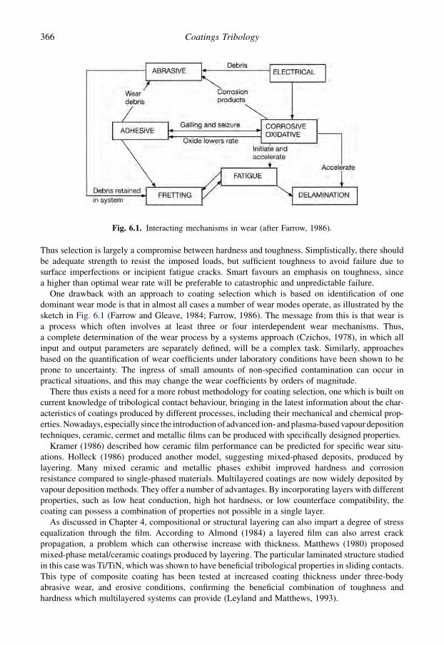
Thus selection is largely a compromise between hardness and toughness. Simplistically, there shouldbe adequate strength to resist the imposed loads, but sufficient toughness to avoid failure due tosurface imperfections or incipient fatigue cracks. Smart favours an emphasis on toughness, sincea higher than optimal wear rate will be preferable to catastrophic and unpredictable failure.
One drawback with an approach to coating selection which is based on identification of onedominant wear mode is that in almost all cases a number of wear modes operate, as illustrated by thesketch in Fig. 6.1 (Farrow and Gleave, 1984; Farrow, 1986). The message from this is that wear isa process which often involves at least three or four interdependent wear mechanisms. Thus,a complete determination of the wear process by a systems approach (Czichos, 1978), in which allinput and output parameters are separately defined, will be a complex task. Similarly, approachesbased on the quantification of wear coefficients under laboratory conditions have been shown to beprone to uncertainty. The ingress of small amounts of non-specified contamination can occur inpractical situations, and this may change the wear coefficients by orders of magnitude.
There thus exists a need for a more robust methodology for coating selection, one which is built oncurrent knowledge of tribological contact behaviour, bringing in the latest information about the char-acteristics of coatings produced by different processes, including their mechanical and chemical prop-erties. Nowadays, especially since the introduction of advanced ion- and plasma-based vapour depositiontechniques, ceramic, cermet and metallic films can be produced with specifically designed properties.
Kramer (1986) described how ceramic film performance can be predicted for specific wear situ-ations. Holleck (1986) produced another model, suggesting mixed-phased deposits, produced bylayering. Many mixed ceramic and metallic phases exhibit improved hardness and corrosionresistance compared to single-phased materials. Multilayered coatings are now widely deposited byvapour deposition methods. They offer a number of advantages. By incorporating layers with differentproperties, such as low heat conduction, high hot hardness, or low counterface compatibility, thecoating can possess a combination of properties not possible in a single layer.
As discussed in Chapter 4, compositional or structural layering can also impart a degree of stressequalization through the film. According to Almond (1984) a layered film can also arrest crackpropagation, a problem which can otherwise increase with thickness. Matthews (1980) proposedmixed-phase metal/ceramic coatings produced by layering. The particular laminated structure studiedin this case was Ti/TiN, which was shown to have beneficial tribological properties in sliding contacts.This type of composite coating has been tested at increased coating thickness under three-bodyabrasive wear, and erosive conditions, confirming the beneficial combination of toughness andhardness which multilayered systems can provide (Leyland and Matthews, 1993).
Fig. 6.1. Interacting mechanisms in wear (after Farrow, 1986).
366 Coatings Tribology

The traditional wear mechanism approach to selection of coatings included for many years a lack ofsuitable coatings to fulfil the stringent requirements of a rigorous selection procedure. Now theavailability of improved coatings and an improvement in the theoretical understanding of tribologicalcontacts means that there is a better basis for finding more elegant solutions to the selection problemand the development of aids for the designer. This is particularly true given the widening availabilityof computer systems which can provide support for selection by allowing design simulations, data-base compilation and even logic-based selection.
In the traditional positive selection approach a possible solution is tried, and if it gives a satisfactoryimprovement, it is used. This often results in better solutions being rejected by default. A moreadvanced approach is progressive elimination, in which all solutions are considered, and those that areless feasible are eliminated (James, 1976, 1978). Progressive filtering is carried out until the optimumsolution is identified. In the following a methodical approach is described. The discipline inherent inthis technique encourages the acquisition of information, rather than the assumption of knowledge,and promotes the investigation of alternative ways of solving minor problems, which might otherwisebe obstructing a highly desirable solution.
6.3 A Methodology for Coating Selection
An improved approach to coating selection should allow progressive elimination and lend itself toa computerized implementation. Furthermore, an approach which avoids the identification of onedominant wear mechanism would be desirable. A systematic framework fulfilling these goals isdescribed below. This is intended to provide a basis for minimizing the probability of tribologicalproblems by indicating the material property limitations and characteristics needed (Matthews et al.,1992b, 2007).
The approach is based on matching the requirements of the application – what is needed? – with thecombinations of properties that can be offered by different coatings – what is possible? – as shown inFig. 6.2. The possible solutions are found by progressively eliminating those coatings that do notpossess the required combination of properties. In order to achieve a successful marriage between theneeds and the possibilities, it is necessary to express the requirements in a way that can be directlycompared to the known properties and characteristics of coatings and coating processes. In effect, thecomponent design engineer must translate the requirements into a language that can be understood bythe coating process engineer. The different stages of the methodology and how the selection procedureis implemented are shown in Fig. 6.2.
The purpose of stages 1, 2 and 3 is to derive the correct tribological requirements needed for thematch by successively refining the design specification. It is convenient to make a distinction betweensurface functional requirements (stage 4), non-functional requirements (stage 5) and economic andprocurement requirements (stage 6). Various aspects that should be taken into considerationconcerning the functional tribological and coating requirements (stages 3 and 4) have been criticallydiscussed by Godet et al. (1991). Brief descriptions of the stages are given below. Examples of thecontents of each stage are provided in Table 6.1.
Stage 1: Application and design study. This stage is similar to the early part of all engineering designprocedures and involves selection of the global design requirements leading to a general designspecification and a definition of the expected working conditions for the complete design, also referredto as embodiment design (Pahl and Beitz, 1984). The tribologically critical components are identified.
Stage 2: Component specification. The second stage involves a more detailed analysis of the criticalcomponents. For each of these, the specific contact and service conditions, such as contact geometries,forces, velocities, environment, etc., and the applicable constraints, such as overall componentdimensions and dimensional accuracies, costs, desired lifetime, etc., are specified. It is necessary todistinguish between the part to be considered for coating (designated part 1) and any counterpart
367Coating Selection

(designated part 2) that is involved in the tribological contact. It is assumed that the material of part 2is pre-specified. The next stage in the methodology is to convert the specifications in stage 2 intorequirements of the coatings and coating processes to be considered.
Stage 3: Functional tribological requirements. The functional tribological requirements are those thatare essential to the tribological performance of the design and will include noise and vibration lim-itations as well as friction or traction force requirements and allowable wear rates.
Stage 4: Functional coating requirements. These are the required limits on the appropriate surfaceproperties, needed in order to fulfil the functional tribological requirements under the applicableservice conditions. Typical limits are yield strength and elastic modulus, hardness, surface roughness,thickness of the coating, wear factor, etc.
Stage 5: Non-functional requirements. These requirements are not essential to the tribologicalfunction of the component but, nonetheless, represent important constraints on the coating materialsand processes that can be applied. Examples are the dimensions required to be coated, maximumallowable dimensional changes associated with the coating or coating process, the need to mask offcertain parts of the component from coating, desired surface colour, visual perception, preferredcoating materials and processes, etc.
Stage 6: Economic and procurement requirements. Aspects concerning the allowable costs of the finalcomponent and the ease with which a coating can be obtained, either in-house or externally, arecovered by these requirements. Also included are legal, environmental and availability factors whichmay prohibit or favour certain coatings or coating processes.
Stage 7: Coating process characteristics. Stages 7, 8 and 9 can be thought of as filters, positivelyeliminating those coating processes or coatings that are not able to meet the requirements in stages
Fig. 6.2. Methodology for tribological coating selection.
368 Coatings Tribology

4, 5 and 6. Stages 7 and 8 can be considered as coarse filters because they are concerned with theinvariable characteristics of particular coating processes or coating materials. Stage 7 deals with theprocess characteristics and property ranges that are valid for all coatings applied using a certainprocess such as CVD, PVD or plasma thermal spraying. In this way, if a requirement such asa maximum allowable coating thickness or maximum as-coated surface roughness does not fall withinthe range that is practically feasible for a particular process, then all coatings applied using thisprocess can be eliminated. If a particular coating material is required, only those processes capable ofdepositing this material need be considered.
Stage 8: Coating material characteristics. Similar to stage 7, stage 8 concerns coating materialproperty ranges and characteristics that, for practical purposes, can be considered to be independent ofthe coating process used. For example, the hardness of titanium nitride typically lies between 17 and30 GPa, irrespective of whether a CVD or a PVD process is used. The ranges of engineering materialproperties have been collected in numerous design charts to support material selection in mechanical
Table 6.1. Examples of the information provided at the different stages in the coating selectionmethodology.
Stage Examples (3 and 4 dependent on the applicable tribological situation)
1. Application anddesign study
General working conditions, appraisal of design requirements, overallmachinery design, identification of critical components.
2. Componentspecification
Geometry of the contact between parts 1 and 2. Material and surfaceroughness of part 2. Working environment: abrasive particles, liquid,gas, temperature. Forces on the contact. Velocities involved. Nature ofthe motion involved. Desired lifetime. Maximum allowabletolerance.
3. Functionaltribologicalrequirements
Friction or traction force requirements: initial and steady-state. Noiseand vibration. Avoidance of localized plastic deformation, fracture,surface fatigue and fretting. Wear rate.
4. Functionalcoatingrequirements
Yield strength of substrate in relation to the reduced elastic modulus.Thickness requirement for coating. Wear rate in relation to thecounterpart. Required coating and substrate hardness. Surfaceroughness. Preferred coating types.
5. Non-functionalrequirements
Dimensions and weights of parts to be considered for coating.Maximum allowable dimensional changes associated with the coatingor coating process. Thickness tolerance. Finishing requirements.Requirement for the masking-off of certain parts of the componentfrom coating. Requirement for coating to penetrate holes and recesses.Desired surface colour. Preferred coating materials and processes. Anylimitations on the substrate material for the coating.
6. Economic andprocurementrequirements
Allowable costs. Delivery time. Availability in-house, locally andworldwide. Legal and environmental constraints.
7. Coating processcharacteristics
Partial-coating ability. Penetration ability. Environmental friendliness.Ranges of possible thickness, precision of thickness, deposition rate,process temperature and relative distortion of workpiece, maximumcoatable dimensions, cost per unit surface area, surface roughnesschange, relative adhesion and permissible substrates.
8. Coating materialcharacteristics
Ranges of colour, elastic modulus, Poisson’s ratio, hardness, fracturetoughness, chemical reactivity, wear rate and friction coefficient.
9. Specific coatingmaterial and processcharacteristics
Narrower and combined ranges or specific values for the propertiesgiven in 7 and 8.
369Coating Selection

design by Ashby (1999). The charts cover material characteristics like Young’s modulus, strength,hardness, fracture toughness, thermal conductivity, dry wear rate, density, relative cost, energycontent, but are available only for bulk materials.
Stage 9: Specific coating material and process characteristics. This stage is in some respects a re-finement of stages 7 and 8, dealing with the property ranges and characteristics for specific coatingmaterial–process combinations. In this way, a differentiation can be made between the propertyranges of similar coatings deposited by different processes or varied conditions.
The most difficult aspects of the methodology involve the specification of the required tribologicalbehaviour of the surface (stage 3) and the conversion of this information into surface propertyrequirements (stage 4). We have earlier seen that tribological quantities such as friction coefficient andwear rate are strongly influenced by the tribological system, depending not only on the natures of theinteracting surfaces involved in the tribological contact, but also on system conditions includingforces, velocities, temperature, atmosphere, etc.
The system parameters are often variable and are not mutually independent, adding further complexityto the problem of predicting tribological behaviour. It is therefore not surprising that, in spite of intensiveresearch, there are many questions in connection with the relationships between material surface prop-erties, tribological system conditions and tribological behaviour which are still today unclear.
However, it is still possible to define which surface characteristics influence the tribologicalmechanisms occurring and are therefore important in determining the friction and wear behaviour ofcoated surfaces. This subject was reviewed in Chapter 3 and on that basis the following parameters areof major importance:
1. Yield strength and plasticity of the coating and the substrate (related to abrasive wear resistanceand load-carrying capacity; quantified by hardness).
2. Elasticity of the coating and the substrate (related to stress and strain generation; quantified byYoung’s modulus and Poisson’s ratio).
3. Tensile strength of the coating and the substrate (related to fracture resistance; quantified byfracture toughness).
4. Shear strength of the coating/substrate interface (related to the coating delamination resistance;quantified by the interfacial fracture toughness or adhesive strength).
5. Shear strength of the coating or any microfilms present on the coating surface or generated duringservice (related to friction).
6. Thickness of the coating (related to adhesive wear allowance and stress generation).7. Roughness of the surfaces (related to friction and wear).
Ideally the design values for the above properties would be derived from knowledge of the requiredwear rate and friction coefficient and the known service conditions. However, the generalunderstanding of the tribological phenomena involved, in addition to the theoretical modelsconcerning the contact mechanics of layered surfaces, are not yet at a stage that enables compre-hensive relationships to be derived from fundamental principles. Moreover, data on several of theproperties listed above, in particular interface shear strengths and properties of microfilms, are notavailable for the majority of coatings. Unlike bulk materials, for which comprehensive and freelyaccessible databases exist, a general database for coatings is not available.
An alternative approach to theoretical models is to combine some of the more practically applicablecontact mechanics theories with rules of thumb that, although not yet fully explainable on theoreticalgrounds, are nonetheless well established with tribological design engineers. Such an approach totribological design has been suggested previously (Thijsse, 1989) and has been further developed(Matthews et al., 1993; Franklin, 2008). The intention of this approach is not to calculate the exactproperty requirements but rather to provide, with a reasonable safety margin, a reliable indicationof the material property limitations and characteristics needed. This enables the design engineer to
370 Coatings Tribology

effectively minimize the probability of tribological problems occurring in service; this should besupported by testing to simulate in-service conditions.
6.4 Selection Rules
The design methodology described above is founded on a number of practical design rules, each ofwhich has one or more materials selection criteria associated with it. Depending on the design sit-uation, one or more, commonly several, of these rules is appropriate. By applying the rules succes-sively, the materials selection requirements are progressively refined. The methodology canaccommodate many of the possible general tribological problems that occur in practical design sit-uations. The selection of which rules are appropriate for a particular design situation is based on thefollowing factors:
� the service conditions under which the component is required to perform, including the type ofrelative motion between the surfaces,� the limitations of the rules, and� the constraints imposed by the application of the materials used.
It is very important to note that the methodology is based on the rules which relate to the classificationof the contact type or types, not to the identification of a dominant wear mechanism. This approachrecognizes that more than one wear mechanism may occur in a given contact.
The following rules have been identified using contact conditions illustrated in Fig. 6.3.
Rule 1 – Contact stresses: Stresses generated by the surface loads should be below the yield strengthand the fracture limits of the surface.
The most important criterion that must be satisfied by the contacting materials in many potential wearsituations is that plastic deformation or fracture in the contact region must be avoided under bothstationary and moving conditions. In the case of coated and surface-treated materials, this also appliesto the substrate material. If considerable plastic deformation or fracture does occur, severe wear islikely to take place from the onset of motion (Tangena, 1987). This does not include failure ofroughness peaks, which is inevitable in most contact situations.
Coated and surface-treated surfaces require special consideration because the mechanical propertiesare non-isotropic. The variation in material properties such as yield strength, hardness, elastic modulus,Poisson’s ratio and fracture toughness with the depth from the surface must be taken into account.
The rule is based on the theory and analytical solutions originated by Hertz (1882) and developed byJohnson (1985) and Hamilton and Goodman (1966). For coated surfaces, use is made of the analyticalsolutions provided by Leroy and Villechaise (1990) and finite element analysis by Laukkanen et al.(2006). The H/E ratio can also be used to indicate the hardness and elastic modulus requirements of thesurface, illustrating the benefits of a suitably low elastic modulus and a suitably high hardness (Leylandand Matthews, 2006). A coating which can deflect with the substrate’s deformation under load is vital,and this requires a long elastic strain to failure, i.e. a high H/E ratio of the coating. It is important to notethat the minimum allowable strengths for materials calculated in this rule are not intended to be used toprovide accurate estimates of the maximum stresses actually occurring. Because the rule is intended fordesign purposes, the worst case situation is used as the basis for the calculations.
Rule 2 – Sliding: Contact temperatures, surface roughness and wear particle generation should be ata level which avoids effects such as accumulated surface melting, asperity and debris interlocking andploughing. Then the conditions are characterized by stable sliding, typically with generated surfacelayers having low shear strength and minimum wear.
The tribological mechanisms involved in sliding are fairly well known and have been describedearlier. In the case of conformal contacts, e.g. flat sliding on a flat surface, the contact is characterized
371Coating Selection
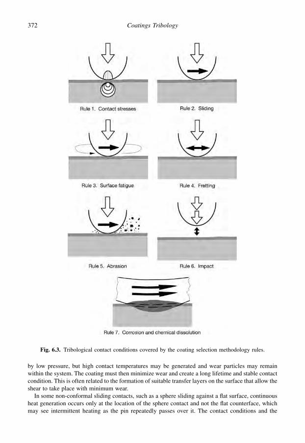
by low pressure, but high contact temperatures may be generated and wear particles may remainwithin the system. The coating must then minimize wear and create a long lifetime and stable contactcondition. This is often related to the formation of suitable transfer layers on the surface that allow theshear to take place with minimum wear.
In some non-conformal sliding contacts, such as a sphere sliding against a flat surface, continuousheat generation occurs only at the location of the sphere contact and not the flat counterface, whichmay see intermittent heating as the pin repeatedly passes over it. The contact conditions and the
Fig. 6.3. Tribological contact conditions covered by the coating selection methodology rules.
372 Coatings Tribology
stresses and strains generated have been modelled and analysed by Holmberg et al. (2003, 2006a, b,2008b). The aim is usually to reduce both friction and wear, and the need to prevent plastic de-formation is paramount. This is the reasoning behind the use of the plasticity index J (Greenwoodand Willamson, 1966), which was originally devised to estimate the surface roughness required toensure that asperity plastic deformation does not take place:
j ¼ ðE0=HÞ$ðRasp=zÞ1=2(6.1)
where E0 is the reduced modulus of the contacting surfaces, H is the hardness of the softer material,Rasp is the typical radius of an asperity and z is the standard deviation of the asperity height distri-bution. Recent development of coatings such as DLC and MoS2 make it possible to achieve super-lubricity and close to zero wear with friction coefficients down to 0.001 and wear rates of only0.0001 $ 10�6 mm3/Nm. However, such tribological performance requires extremely smooth surfacesand a strictly controlled environment. Design criteria for such contacts are basically the same aspresented above and the special conditions that must be considered have been presented by Erdemir(2004a) and Erdemir and Martin (2007).
Rule 3 – Surface fatigue: Coating elasticity and thickness should be of a level to allow deflection andavoid high-stress peaks and simultaneously distribute the stresses. The coating structure should in-hibit crack growth. The substrate and coating strength should be above the level needed to avoidfatigue fracture. The surface should have optimized roughness to allow polishing.
In contact fatigue the surface is repeatedly loaded, and this can be a sliding or rolling action. Thisresults in deterioration of the surface strength and crack initiation and propagation at or below thesurface. The aim of a surface coating is mainly to distribute and decrease the surface stresses and toinhibit crack propagation. Surface fatigue is a complex phenomenon influenced by a large number offactors such as surface roughness and defects, shape, coarseness and distribution of carbides andinclusions. However, both theoretical and empirical relationships between the contact stress, crackpropagation, coating thickness, surface roughness, the composition and the hardness of steels, thelubrication regime and the number of cyclic load changes have been presented in the literature(Niemann, 1960; Rowe and Armstrong, 1982; Kral and Komvopoulos, 1996a; Klafke et al., 2005b;Yonekura et al., 2005; Lindholm and Svahn, 2006; Zhao et al., 2006a, b). Practical experience hasshown that these relationships can be used successfully as a design tool to minimize the chances offailure occurring due to surface fatigue.
The maximum shear stress in a rolling contact is, in the majority of engineering design situations,located some 10 to 100 micrometres below the surface. In addition, when the roughness of the sur-faces is taken into account, it has been shown by Sainsot et al. (1990) that for hard thin coatings witha thickness less than 15 mm on soft substrates, the highest stresses tend to be concentrated at theinterface between the coating and the substrate. However, the fatigue life of a thin coating may beconsiderably longer than that of a thick coating for different reasons. Under similar deformationconditions the thicker coating will experience higher bend stress levels. Furthermore, since manycoatings typically have columnar growth morphology, any crack normal to the surface will be large ina thick coating, and may exceed the critical crack length, whereas in a thin coating this may not be thecase. It has been shown experimentally that in rolling contact fatigue tests hard TiN coatings witha film thickness well below 1 micrometre have up to two orders of magnitude longer lifetime than 2 to3 mm thick similar coatings (Erdemir and Hochman, 1988).
Thickness effects in rolling contact fatigue for a-C:Cr and DLC coatings has been reported byLindholm and Svahn (2006) and Lohr et al. (2006). Polonsky et al. (1997) claim that they have beenable to demonstrate that the rolling contact fatigue life increase achieved with less than 1 mm TiNcoatings was entirely due to polishing of the steel loading balls by the significantly harder TiNcoating. They changed the test procedure and eliminated the polishing effect and observed a some-what negative effect of the TiN coating on the rolling contact fatigue life. Similar mechanisms have
373Coating Selection
been reported for DLC-based coatings in rolling contacts by Harris and Weiner (1998) and Lindholmand Svahn (2006). Doll (2001) and Doll et al. (2004, 2005) give further information on the benefits ofmetal-doped DCL coatings in rolling bearing applications, emphasizing the benefits of nano-composite structures.
Surface treatments, such as carburizing or shot peening, which can induce compressive in-planestress in the surface, can provide benefits to fatigue life, by ensuring that in-service surface tensilestresses are reduced and crack opening effects are restricted. Promising results on improvements inrolling contact fatigue life by the use of thin surface coatings have been reported for mechanicalcomponents like gears (Amaro et al., 2005), bearings (Sjostrom and Wikstrom, 2001; Doll et al., 2004,2005; Yonekura et al., 2005; Vanhulsel et al., 2007) and valve lifters (Lindholm and Svahn, 2006).
Rule 4 – Fretting: The coating should enhance the generation of a low-friction surface layer toaccommodate the movement or be elastic to accommodate deflection and reduce high stresses. Thecoating should increase surface inertness in relation to surface destructive chemical reactions. Thecoating should hinder crack initiation and crack growth.
Fretting is a special case of fatigue wear at the surface, where the amplitude of reciprocating sliding istypically smaller than the contact length. In the contact the reciprocating friction load producessurface stresses that can result in cracks and asperity detachment. The wear products stay within thecontact region and influence the contact conditions, e.g. concentrating the surface load due to thereleased wear particles and increasing the localized surface stresses. On steel surfaces the contactprocess wears off the oxide layers on the surface, which is then more exposed to chemical reactions.Oxidized wear particles can cause increased abrasion, and the associated volume increase can lead toseizure in closed mechanical systems with a close fit. Energy analysis of both uncoated and coatedsurfaces in fretting wear has been useful in structuring the involved wear and friction mechanisms(Fouvry et al., 2003; Liskiewicz et al., 2004; Liskiewicz and Fouvry, 2005b; Kapsa et al., 2005).
Fretting wear or fretting corrosion can occur in electrical switch contacts, mechanical detachablejoints such as press-fitted, bolted or riveted joints, and in precision-engineering constructions whichare digitally controlled and exhibit limit cycling. The results of fretting are loss of fit in mechanicaljoints, seizure or high friction in moveable joints and high electrical resistance in electrical contacts.
The low-amplitude movements necessary for fretting to occur can originate from undampedmachine vibrations, electronic position control or thermal expansion–contraction effects. In order tominimize the chances of problems occurring in a potential fretting wear situation, use can be madeof certain coatings and surface treatments which have been proven to provide effective solutions.Examples are phosphating and sulphiding treatments, MoS2 coatings and ceramic coatings. In thelatter case, both surfaces would normally require coating (see section 7.8.2). Even elastic rubbercoatings have been applied with good results (Baek and Khonsari, 2005).
It is possible in some cases to build up favourable transfer of reaction layers on the surfaces thatdecrease the shear strength and friction. Fretting wear is often most efficiently reduced by effectivemacromechanical design measures, e.g. to control the displacements and stresses induced in thecontact. However, it is also possible to modify the frictional conditions to reduce friction, e.g. bymeans of a solid lubricant coating such as MoS2 (Zhang et al., 2003a), PTFE (Langlade and Vannes,2005) and layered or composite coatings like DLC on TiN (Klafke, 2004c), MoS2 doped TiN coating(Cosemans et al., 2003) and MoS2 doped in Cu–Ni–In coating (Fridrici et al., 2003). There can beadvantages in providing such additions as phases in a nanocomposite coating.
Rule 5 – Abrasion: In abrasion the coating should have high hardness to inhibit groove formation andbe thick enough to prevent abradant penetration.
In abrasion, typically, a hard counterbody moves against and ploughs through a softer material andthus the hardness of the softer material is of considerable importance. The aim of the surface materialchoice is to inhibit plastic deformation, such as grooving, on the surface. Usually thick coatings are
374 Coatings Tribology

used in abrasive contact conditions, and the performance of thin coatings such as PVD TiN is oftenpoor under such conditions. This is partly due to the thickness limitations of hard PVD and CVDcoatings, their lack of toughness and the need for effective load support, especially under three-bodyabrasion with sharp and hard abrasive particles.
The load-support requirement, to prevent adverse macromechanical mechanisms, can be fulfilledby utilizing interlayers such as electroless nickel (Matthews and Leyland, 1995). It has been foundthat by multilayering Ti and TiN films it is possible to produce a composite coating which is both hardand tough, thus controlling micromechanical mechanisms and performing well in abrasive conditions(Leyland and Matthews, 1994). In comparisons of the abrasive wear resistance of different coatingsDLC, CrN, TiN, TiCN and ZrN have been successful (Van Acker and Vercammen, 2004; Tucker,2004). The abrasive mechanisms related to TiN coatings are presented in section 4.4.1, DLC coatingsin section 4.5.3 and diamond coatings in section 4.5.2.
The rule includes the specific case when foreign particles, not originating from wear, are present inthe contact. This is based on simple rules of thumb (Eyre, 1992), which are applied by practisingtribological design engineers. It provides a minimum surface hardness requirement and, in the case ofcoatings, a thickness requirement. When this hardness requirement cannot be met by the availablecoatings, the non-proportionality between hardness and abrasion resistance, which is observed whencomparing different material types, is approximated using empirical relationships compiled frompublished data (Khruschov, 1974).
Rule 6 – Impact: The coating and substrate should be sufficiently elastic to deflect and absorb impactenergy and a flexible well-adhered coating/substrate interface layer is required. In erosion withnormal impacts the coating should be sufficiently elastic to avoid high-stress peaks. In inclinederosion the coating should be hard enough to avoid grooving.
Impact resistance is required under conditions of repetitive dynamic loading. It may be regarded asanother form of contact fatigue, sometimes in combination with static contact loading. In suchconditions, a coated surface must possess a high toughness in order to absorb the impacts that result inrepeated stress states and energy input to the surface. Ideally, this energy should be absorbed elas-tically, so that no permanent deformation results. This ability to absorb energy is governed by theelastic resilience of the material, which is defined as Y2/2E, where Y is the yield stress. Since thehardness is typically about 3Y, we can see that this means that we need to maximize H and minimize Ein order to increase the elastic resilience. The maximum value of the contact pressure occurring ina contact as a result of an elastic impact between two massive bodies can be estimated from contactmechanics theory (Johnson, 1985).
We stated above that, ideally, the impact energy should be absorbed elastically and that is generallythe case. However, since fracture toughness can be enhanced by having a ductile constituent present,there are arguments for having a nanocomposite coating structure with a small amount of a ductilephase present, if fracture toughness is to be enhanced, i.e. to increase the ‘ultimate’ resilience of thesurface – as defined by the total area under the stress–strain curve.
The impact mechanism is one component in erosion wear. Erosion can take several forms – for ex-ample solid particle, liquid droplet and cavitation – and the rules pertinent to its avoidance may combineeffects of abrasion, impact, fatigue, corrosion and dissolution and take into account parameters such asparticle velocity, size and shape, etc. Hard and thin PVD coatings like TiN, DLC, CrN, TiAlN have beeninvestigated for erosive resistance (Iwai et al., 2001; Batista et al., 2003; Fujisawa et al., 2006) and goodresults has been achieved especially with TiN based multilayer coatings (Iwai et al., 2001) and duplexcoatings with (Ti,Al)N and Cr–N on pre-nitrided steel (Batista et al., 2003).
Rule 7 – Corrosion and chemical dissolution:
Corrosion condition: The coating should be inert, dense and pore free to prevent chemical attack of itand the substrate or it should have suitable sacrificial properties.
375Coating Selection

Moving mechanical contacts within a corrosive environment is likely to see both accelerated wear andcorrosion, as the corrosion products are continually being removed to reveal a clean surface. This wasmentioned above for fretting, but can also occur for the other contact types mentioned here. To reduceand control corrosion, coatings need to be dense and pore free, which typically applies for nano-composites. The fine grain size of nanocomposites leads to a more uniform corrosion, rather thanlocalized pitting, which can be a particular problem with thin ceramic coatings, often producingaccelerated substrate corrosion at pin-hole defects. It has also been suggested that the fine grainstructure can suppress galvanic corrosion effects which can occur within conventional polycrystallinemetallic and composite coatings. Certain coatings, such as zinc, can provide sacrificial protection tosteel due to their more negative electrode potentials – which means that they will protect the substratefrom corrosion, e.g. in an aqueous environment.
Chemical dissolution condition: The coating should have high thermal and chemical stability, hightoughness and high hardness, low adhesion to the counterface material and high adhesion to thesubstrate and be dense to inhibit dissolution from the substrate.
The rule above applies especially to the case of typical chemical dissolution dominated tribochemicalwear when a workpiece material is moving over a cutting tool. The aim of a coating on the cutting toolsurface is to resist the high-temperature conditions, to reduce friction and thus heat generation, toinhibit dissolution of the surface material and reduce scratches produced by hard elements in theworkpiece material (see section 7.5). Thin hard coatings of nitrides and carbides match these re-quirements well and are used successfully. In metal-cutting applications the resistance of TiN films tooxidation has been improved by employing mixed-phase nanolayered and nanocomposite ceramics,sometimes with phase additions to help form a stable oxide on the surface (Holmberg and Matthews,2005). Wear due to the chemical effects of dissolution and diffusion can be accommodated by usingrules such as those developed by Kramer and Suh (1980) and applying equations for forces andstresses at the interface listed by (Grzesik, 2000).
Rule 8 – Lubricated condition: The coating surface should function beneficially with the lubricant. Itshould either react with the lubricant additives to generate a low shear strength boundary lubricantsurface film or it should have the ability to generate a low shear strength surface layer despite thepresence of the lubricant.
Most of the current research on surface coatings deals with their performance in dry conditions, someeven in vacuum or in an inert gas. However, there are numerous applications, e.g. related to engines,transmissions and seals, where the coating is expected to perform in a liquid, often in oil. In the full-film lubrication regime, the oil lubricant carries the load and separates the surfaces from each otherand the shear takes place in the lubricant. The role of the coating is then to act as a safety layer thatcomes into action when the lubricant film fails for one reason or another. Thus, the coated surface isexpected to have good tribological performance in boundary-lubricated conditions where surfaces arepartly in direct contact with each other and surrounded by oil.
It is important to consider the influence that the lubricant has on the effectiveness of the tribofilmformation process. When the lubricant contains reactive additives and the contact is in the boundarylubrication regime, a reaction film is formed on top of the surface and the shear takes place in this film.The film is typically formed by chemical reaction between oil additive elements such as Zn, S, Cl, P orMo and the steel surface and is enhanced by high temperature (see section 3.1.5). The basicmechanical aspects related to boundary-lubricated coated surfaces including effects of inherent stressin the coating, its thickness, structural integrity and surface roughness on the tribological performancehave been derived by Komvopoluos (1991a, b).
For a coating to be effective in such conditions it is necessary either that it has the ability to reactchemically with the additives and form a strong low shear strength reaction film, or that it has theability to produce a strong and low shear strength surface layer that protects the contact from
376 Coatings Tribology

destruction. Ronkainen et al. (1998a) showed how a reaction layer is built up on a steel ball slidingagainst a steel surface in lubrication oil with additives. Very similar tribological performance wasachieved with the ball sliding in dry conditions against a DLC coating and then a transfer layer wasformed on the steel ball. When the steel ball was sliding against the DLC layer in oil lubricatedconditions no visible transfer layer was formed but the tribological performance was in the same rangeas in the previous cases. This indicates that this DLC coating did not really improve the friction andwear in an oil lubricated contact, but could act as a safety layer in the case of lubricant loss or failure(Ronkainen, 2001).
Metal doping of DLC coatings has turned out to improve the ability to build up a boundarylubrication film on the surface and result in improved tribological performance. In combination withconventional extreme pressure (EP) additives this has been reported for W-doped DLC (Jacobson andHogmark, 2001; Podgornik et al., 2006a), Cr-doped DLC (Lindholm and Svahn, 2006) and Si-, Ti-,W-doped DLC (Vercammen et al., 2004). Enhanced tribological performance was also observed forTi-, Mo- and Fe-doped DLC in oil containing ZDDP and MoDTC additives (Miyake et al., 2004).Similar improvements has been achieved with nanocomposite coatings based on carbon with metaladditions, designed to create a transfer layer, and thus the ability to run both dry or with a lubricantwas enhanced (Doll et al., 2005).
6.5 Design Guidelines
In various papers the present authors and their collaborators discussed the empirical and theoreticaldesign guidelines that are appropriate to the above contact conditions (Matthews et al., 1992b;Franklin and Dijkman, 1995). A comprehensive resume of eight design guidelines pertinent to theselection of materials and coatings to resist wear was presented. Rather than providing a guarantee forthe prevention of wear problems, the guidelines are intended to assist design engineers in minimizingthe likelihood of wear problems occurring when the design goes into service. The guidelinespresented in Franklin and Dijkman (1995) cover the following phenomena:
� Contact overloading (CO): intended to avoid plastic deformation in the contact.� Fretting (FR): designed to assess the propensity for fretting to occur, so that suitable treatments or
coatings can be applied.� Excessive material transfer (MT): based on knowledge of material pairings which should be
avoided in order to minimize the chances of adhesive material transfer occurring.� Two- and three-body abrasion (2B and 3B): based essentially on the well-known rule of thumb
that if a surface is to resist abrasion its hardness should be at least 30% harder than any abradantpresent.� Negligible wear (NW): based on the work of Bayer et al. (1969). This guideline checks whether the
maximum shear stress in the contact region exceeds a critical value and also considers the possiblepresence of a lubricant.� Surface fatigue (SF): based on empirical data and thus restricted to materials for which data has
been assembled (mostly steels).� Steady-state wear factor (WF): this guideline examines the wear rate data and the scatter available
for the selected materials pairings to predict wear life.
In effect, the boundary conditions for applying the above guidelines are determined by the dominatingphenomena listed in Table 6.2, and they are typically applied in order to ensure that the requiredproperties are achieved in the surface and near-surface regions (Matthews et al., 2007).
The contact overload guideline states basically that the elastic limit should not be exceeded in thecontact. This particular rule, although simple in concept, is complex in application, particularly whenapplied to coatings. This is because the limit of load-carrying capacity may in fact be determined by
377Coating Selection
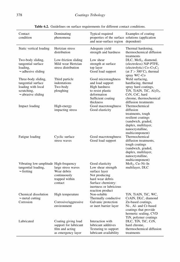
Table 6.2. Guidelines on surface requirements for different contact conditions.
Contactcondition
Dominatingphenomena
Typical requiredproperties of the surfaceand near-surface region
Examples of coatingsolutions (applicationdependent)
Static vertical loading Hertzian stressdistribution
Adequate yieldstrength and hardness
Thermal hardening,thermochemical diffusiontreatments
Two-body sliding,tangential surfaceloading,wadhesive sliding
Low-friction slidingMild wear Hertzianstress distribution
Low shearstrength at surfacetop layerGood load support
DLC, MoS2, diamond,(electroless) NiP-PTFE,(electrolytic) Co–Cr3C2
(at T> 300�C), thermalspray WC–Co
Three-body sliding,tangential surfaceloading with localscratching,wabrasive sliding
Third particleindentationsTwo-bodyploughing
Good microtoughnessand load supportHigh hardnessto resist plasticdeformationSufficient coatingthickness
Weld surfacing,hardfacing, thermalspray hard coatings,TiN, TiAlN, TiC, Al2O3,CrN, CrC, hardchrome, thermochemicaldiffusion treatments
Impact loading High-energyimpacting stress
Good macrotoughnessGood elasticity
Thermochemicaldiffusiontreatments, toughresilient coatings(sandwich, graded,duplex, multilayer,nanocrystalline,multicomponent)
Fatigue loading Cyclic surfacestress waves
Good macrotoughnessGood load support
Thermochemicaldiffusion treatments,tough coatings(sandwich, graded,duplex, multilayer,nanocrystalline,multicomponent)
Vibrating low-amplitudetangential loading,wfretting
High-frequencylarge stress wavesWear debriscontinuouslytrapped withincontact
Good elasticityLow shear strengthsurface layerNot producinghard wear debrisSurface chemistry:inertness or lubriciousreaction product
MoS2, Cu–Ni–Inmultilayer, DLC
Chemical dissolutionwmetal cutting
High temperature Non-solubleThermally conductive
TiN, TiAlN, TiC, WC,CrAlN, DLC, diamond
Corrosion Corrosive/aggressiveenvironment
Galvanic protectionor inert barrier layer
Zn-based coatings,Ni-, Al- and Cr-basedcoatings that providehermetic sealing, CVDTiN, polymer coatings
Lubricated Coating giving loadsupport for lubricantfilm and actingas emergency layer
Interaction withlubricant additivesTexturing to supportlubricant availability
DLC, TiN, TiC, CrN,hard chrome,thermochemical diffusiontreatments
378 Coatings Tribology

several different effects, not just the need to avoid exceeding the elastic limit. In addition, the values ofappropriate properties relating to the failure criteria of coatings are often poorly known to the designengineer. Figure 4.100 illustrates that the contact load limit may be defined in several ways, such ascoating debonding, coating cracking, substrate cracking, substrate or coating plastic deformation oreven elastic deformation which might take a surface, or component, outside its designed operatingdimensions. The hardness to elastic modulus of the coating has a key role in determining the ability ofthe coating and substrate to accommodate elastic strains without failure. Without adequate me-chanical properties at the surface the inability to carry the required contact pressure can result in a risein ploughing, coating fracture, plastic yield or fracture under the coating.
Even if the basic boundary conditions for applicability are met, the extent to which these guidelinesmay be applicable to a specific contact situation is left to the judgement of the user. It would be highlyunlikely that one rule would suffice in any one particular contact condition, and it is most likely threeor more would have to be applied in order to gain a reasonable level of confidence that a particularsurface material pairing will perform satisfactorily.
It should be noted that the guidelines presented in Franklin and Dijkman (1995) have their origin intribological theories relating to uncoated surfaces. Only now are robust models being developedwhich permit a thorough understanding of coated surface response to various contact types. One suchmodel has been developed by Holmberg et al. (2006a, b) and Laukkanen et al. (2006) for a slidingcontact on a coated surface.
6.6 Expert Systems
The availability of computer hardware and software with ever greater capabilities will enable con-siderable strides to be made in overcoming the coating selection problem. In particular, the de-velopment of computer expert systems – also called knowledge-based systems – is expected by someto have an increasing impact. While the early promise of such systems has not yet been fulfilled, theystill represent a potentially powerful tool in the engineer’s armoury. Expert systems are defined ascomputer programs which are specifically developed to encode expert knowledge and make it easilyavailable to the user, often in a conversation mode. Unlike conventional hardwired programmes, mostexpert systems have a separate reasoning module or interpreter, which manipulates knowledge toreach a conclusion. This allows the knowledge base, e.g. containing coating property experience, to bestored separately in the programme.
Because the knowledge is separate from the inference procedure the information can be updatedeasily without rewriting the whole system. The knowledge used for a consultation and the decisionpath can be monitored to provide an explanation for any decisions reached. This latter point isespecially important if designers are to have confidence in the system.
There are two main kinds of knowledge in an expert system. The first is the hard data, for examplematerial properties. The second knowledge comprises the heuristic rules or specialist expertise used inthe methodology of selection. An everyday illustration of this distinction is that of the taxi driver. Themap of the city is the basic data, while the heuristics are represented by his knowledge of the relativemerits of alternative routes under the likely conditions of traffic at various times.
There are many computer programs which are described as expert systems but which are merelydatabase systems with only the first type of knowledge. Of course, one of the problems encountered inconstructing a knowledge base is acquiring or eliciting the expert knowledge, most of which will bediffuse and in the head of the expert. Given that the expertise can be obtained, the problem remains ofhow to represent it in the computer. Many forms of representation techniques are available to thesystem builder, but rules are the most common method of representing knowledge.
Despite the large volume of literature published about expert systems, very little has been writtenabout the use of such systems for coating selection. There exist several database systems for materials
379Coating Selection

selection but considerably fewer knowledge-based ones (Tallian, 1987). Database systems generallyonly perform searches of materials based on data sets entered by the user, returning materials whosespecifications match or exceed those entered. Expert or knowledge-based systems are generallycharacterized by their ability to avoid asking for unnecessary data input and the inclusion of someform of selection procedure rather than a simple search.
Some examples of expert systems in the tribology field are described below.TRIBSEL. A number of coating selection expert systems were developed in the 1980s and 1990s. Eachone was to some extent a development of earlier systems (Matthews and Swift, 1983; Syan et al.,1986, 1987; Matthews et al., 1991b; Robinson et al., 1993). The initial work tended to emphasize theidentification of wear mechanisms, and to apply mathematical models. In practice, the number ofoccasions when a strictly mathematical approach to selection can be utilized was found to be verylimited. Even the metal-cutting situation, which is well documented and was thought to be covered byonly two dominant wear mechanisms, has been found to be difficult to model (Kramer and Judd,1985). Thus it was necessary to devise a system that could avoid the need to identify the wearmechanisms.
The system used an approach based on 15 main criteria which were found to be inherent in thereasoning processes carried out by human experts. These criteria are listed in Table 6.3.
Of course, these cannot be fully specified by just 15 questions, and 31 factors were identified whichtogether sufficiently define all of the criteria. These are broken down into five factor groups:
� operating constraints,� processing constraints,� geometrical constraints,� topographical constraints, and� economic constraints.
Three sample rules are given in Table 6.4.The approach used has been to consider coating and treatment technologies in generic groups.
A consultation will start with the hypothesis that all of these will be suitable. As the user suppliesinformation about a particular application the system uses the rules in its knowledge base to reject anythat are unsuitable. Thus the process is one of progressive elimination, which as mentioned earlier isconsidered desirable
Within the heading of operating constraints come factors such as the maximum or minimumoperating temperature, the operating environment, contact type (point, line, etc.) and loading type
Table 6.3. Criteria used in coating selection.
Operating temperatureOperating environmentCounterface materialCounterface hardnessSubstrate materialSubstrate hardnessContact pressureContact geometryRelative motion typeRelative speedsSurface finishComponent size and shapeCoating thickness and uniformityQuantity of partsEconomics, including versatility
380 Coatings Tribology

(rolling, sliding, impact, etc.). The system is based on an enormous amount of case history information,as recalled by several human experts after a lifetime of experience. This information was extracted byasking them when particular coating or treatment types were or were not successful. An advocate of thewear mechanism identification approach might argue that the questioning in this factor group categoryis merely identifying the likely wear types. At no point, however, is such information requested from thecomputer, neither does it possess any knowledge of wear mechanisms per se.
Certain coatings are eliminated because of their poor suitability for the operating constraintsimposed by the processing method. These include factors such as the maximum dimension ofthe component which can be coated, the processing temperature and its possible influence on thecomponent, and production capability factors such as the throughput required.
Next come geometrical constraints, such as the coating uniformity and re-entrant penetrationcapability of the process. These are followed by questions relating to the topographical constraintswhich cover aspects such as the surface finish requirements.
When particular coatings or treatments cannot meet the needs indicated by the designer under eachof these headings, they are rejected. The designer can ask why a particular question is being asked,and the system will respond by explaining the particular reasoning path it is using at that time. It willultimately provide a list of coatings or treatments that will satisfy all of the indicated demands – or ifnone exist it will respond accordingly. The system has relative cost information encoded andinformation about economic quantities and availability which is also available to the designer. A casehistory file of similar applications is also incorporated, which the computer will display if it meets anapplication which it has seen before. Following the development of TRIBSEL, a more advancedsystem known as PRECEPT was devised by Robinson et al. (1993) and Franklin and Dijkman (1995).Subsequently, a proprietary system called ISIS was developed, which incorporated several of themethodologies within the earlier systems.
TRIBEXSY. The Philips TRIBEXSY tribological consultation system is designed to remove theneed for an interview with the tribology expert when a wear problem arises. TRIBEXSY’s dialogue-based approach guides the user through an analysis of the symptoms of the wear problem, by askingquestions about the materials involved, their operating environment, the nature of the contact regimeand the appearance of the damage to the components. This leads to an identification of the type ofwear taking place. The program then searches for possible ways of overcoming the wear problem, bysuggesting the use of different materials, coatings and lubrication regimes. As before, the user is askedquestions about operating conditions and component geometry, in addition to being questioned as tothe possible use of alternative materials and slight design changes.
TRIBEXSY may also be used for consultation in a design situation before a problem arises, al-though as with all expert systems, the more often an unknown is entered in response to the system’s
Table 6.4. Sample rules from TRIBSEL coating selection expert system.
Operating environment rule Material constraint rule Geometrical constraint rule
ifoperating temperature is<200�Cand notsolid erosionand notliquid erosion or cavitationthenmechanical surface workingis a possible choice
ifferrous materialandsubstrate surface finish<6 micronsandcounterface hardness<800 VPNthencarburizing is a possible choice
ifmelting temperature>1000�Candre-entrant capability <0.5and notcomplex shape categorythenwelded carbide is a possiblechoice
381Coating Selection
questioning, the less reliable will be the solutions proposed. TRIBEXSY is text based, and runs viaremote terminals.
Experience with expert systems has shown that the essence of such systems, when developed toa satisfactory performance level, is basically a simple structure of rules. Those expert systems thathave been developed rely first on identifying the correct rules and then on populating those rules withreliable knowledge, which mostly is coating-related data. The benefits gained in developing an expertsystem are then manifested in a systematic methodology, which has validity as either a paper-based ora computer-based system. A robust selection system having the desirable attributes needed for thecomputer expert system invariably creates a selection system which can also be implemented asa structured sequence, such as that presented within this chapter.
Often, if a design engineer or other person selecting coatings follows this sequence it will allow allaspects of the design, such as geometry, bulk material, coating, pre- and post-treatments as well as themanufacturing route, to be considered in an integrated way. Nevertheless, it should be pointed outthat, in all cases where such systems have been used, their purpose has been to determine whether thecoating can provide the basic functionality required, i.e. to operate within the pertaining contactconditions. They are not used to calculate the expected lifetime. When it comes to determining thelifetime of the coating then in-service and model tests are needed (Franklin, 2008). This is evident inthe next chapter, which discusses applications-related performance enhancement.
6.7 Closing Knowledge Gaps
The authors, in their roles as coatings researchers, are often asked to advise on the selection ofa suitable coating to fulfil a given operating need, often as a means of solving a wear problem whichhas arisen due to poor tribological design and practice.
Engineers, materials scientists and others who seek from coatings the same kind of easily specifiedperformance and reliability parameters they achieve with a material chosen for its bulk strength areoften frustrated by the apparent variability associated with selecting a surface coating. The reasons forthis are twofold. One is the difficulty in understanding exactly what the contact conditions are, e.g.in terms of reaction products, operating pressures and temperatures. The second is the lack ofcomparative data about specific coatings. The successful consultant in this field is the one withthe broadest experience of different coatings and specifically the conditions under which they willand will not operate.
In the same way, the value of the computer-based systems lies in the amount of accurate data whichit contains. We stated earlier that there is no comprehensive coatings database available, but there area number of tribology databases (e.g. Woydt, 2000) that are evolving, and as they become populatedwith coatings data then the ultimate goal of an integrated tribological property database can bereached.
While advanced computer and programming techniques can help in the coating selection problem,they cannot be the only solution – otherwise new untried coatings would never be specified. There isthe clear need to bring together the separate skills of the coatings process developer, the coatingsevaluator and the tribological modeller to design and optimize coatings to meet preset needs, withwell-defined quality and reliability. In this way the potential of tribological coatings will be fullyachieved, to the benefit of a wider range of application sectors. Some of those sectors currentlybenefiting are reviewed in the following chapter.
382 Coatings Tribology

CHAPTER 7
Applications
Contents
7.1 General 3837.2 Sliding bearings 3847.3 Rolling contact bearings 3877.4 Gears 3937.5 Tools for cutting 3977.6 Tools for forming 4137.7 Erosion and scratch resistant surfaces 4147.8 Oscillating contacts 4177.9 Magnetic recording devices 4227.10 Microcomponents 4277.11 Biomedical applications 4317.12 Future issues 435
7.1 General
In the previous chapters we have seen that due to the development of existing and new depositiontechniques, designers are now, more than ever before, in a position to change the properties of surfacesand to produce the desired friction and wear properties precisely where they are needed.
The use to coated surfaces to control tribology in a variety of applications is of special interestbecause of the huge effects of friction and wear in relation to energy use, environment and economy.Oil as lubricant was the first significant solution for friction and wear control but there is a trend tolimit its use due to both pollution and cost. Today, surface coatings offer a second major solution forfriction and wear control in our society.
Examples of successful industrial applications of thin hard or soft coatings can be found in en-gineering components, tools for cutting and forming, electronic equipments, consumer goods and inspecial instruments. Examples of coated tribological products in mass production are PVD coatedshaving blades, magnetic storage reader heads, tool inserts, drills, rolling bearings, diesel fuel in-jectors, piston rings, CD/DVD disk moulds, knives and optical lenses.
In engineering components such as sliding bearings, rolling bearings, gears, seals, cams and tap-pets, pistons, cylinders, valves, injectors, plungers, rotors, pumps and transmissions, both hard andsoft coatings are used to reduce wear, increase component lifetimes and reduce friction. Industrialsectors in which such improvements are utilized include the automotive, aircraft and other trans-portation industries, the electronics, consumer goods and metals manufacturing industries as well asthe chemical, food, pharmaceutical, medical and packing industries.
In the very severe surface conditions prevailing at the surface of metal cutting and forming tools,hard coatings are very successfully used to protect the substrate from wear and to increase the toollifetime by several orders of magnitude. Several machinery parts in the pulp and paper industry suchas cutter blades, rollers and grinders, as well as high-speed moving mechanical assemblies in thetextile industry have improved properties due to hard coatings.
383

On components exposed to particle erosion, such as turbine blades and compressor components, orto scratching, such as optical lenses, hard coatings are used to protect against wear. In instrumentswhere the wear of a critical component like a joint or slider influences accuracy or functionality, bothhard and soft coatings are used to extend lifetimes and retain accuracy. These kinds of applications arefound, for example, in computers and aerospace instruments.
Hard low-friction coatings are increasingly used on components in the automotive industry.Friction and adhesion are important in microdevices such as micro-electro-mechanical-systems(MEMS) and here thin film deposition is the solution with the most potential. A new and rapidlygrowing area for coating applications is biomedical components, where improved non-corrosive, non-toxic and biocompatible features are combined with high mechanical strength and fracture toughness.
In this chapter we will discuss experiences with the use of thin surface coatings in a number ofdifferent applications (HMSO, 1986; Matthews et al., 1992a, 1998; Hilton and Fleischauer, 1992;Cartier, 2003; Lampe et al., 2003; Merlo, 2003; Field et al., 2004; Hauert, 2004, 2008; Tung andMcMillan, 2004; Erdemir and Donnet, 2005; Vetter et al., 2005; Neuville and Matthews, 2007; Heau,2008; Van der Kolk, 2008; Matthews, 2008).
7.2 Sliding Bearings
7.2.1 Description of the application
A sliding or plain bearing is basically a very simple machine element where a moving shaft issupported against a stationary housing as shown in Fig. 7.1. Important functional design parametersare the dimensioning of the bearing and the choice of bearing material. It is common to use suchbearings with oil lubrication. With an adequate rotational speed a hydrodynamic pressure will becreated within the oil in the loaded contact zone between the shaft and the bushing. This oil film isthen thick enough to keep the surfaces apart and inhibit wear and provide low friction (see section3.1.5).
The desirable properties for bearing surfaces may be listed as follows:
1. Seizure resistance; i.e. the ability to resist asperity adhesion or welding. Materials, such as whitemetals based on lead and tin, which are soft and have low shear strength, are generally good in thisrespect.
Fig. 7.1. In a sliding bearing the moving shaft is supported by a bearing bushing fixed to the stationaryhousing.
384 Coatings Tribology

2. Compressive strength; i.e. the ability to cope with distortions and deflections of bearings or shafts.This is clearly a property which soft films may lack.
3. Conformability; i.e. the ability to cope with distortions and deflection of bearings or shafts. Also tocope with misalignment during manufacture.
4. Embeddability; i.e. the ability to embed hard particles and therefore prevent them from causingdamage.
5. Fatigue strength. Since most metals have low fatigue strength if they have good deformability,a compromise must usually be made. High operating temperatures can sharply reduce fatigue life,especially of white metals.
6. Corrosion resistance; e.g. high temperatures can cause acid formation in mineral oils. Copper–lead,cadmium and silver alloys are especially vulnerable to attack.
The challenges in the design of hydrodynamic sliding bearings are to calculate and optimize thehydrodynamic conditions and the oil supply grooves. In advanced mechanical systems such as high-speed spindles, computer hard disks with arm sliders and videotape reading heads the interposingmedium is air and they require very precise design and manufacturing. For more detailed informationon sliding bearing design see Lang and Steinhilpher (1978), Barwell (1979), Welsh (1983),Constantinescu et al. (1985) or Brewe (2001).
7.2.2 Improvements by surface coatings
At start-up, slow-down, low-speed, very high load or in dry running conditions there will be directcontact between the shaft and the bushing. The wear and friction can then be minimized by selectionof a suitable material combination and the tribological behaviour can again be manipulated by usingsurface coatings. This sliding situation is in many respects similar to the sliding contacts that we havereferred to quite extensively in Chapter 4. Those sliding contact results and analyses are moreapplicable to sliding bearings than, for example, to rolling bearings or cutting tools.
In the earlier chapters we have frequently referred to friction and wear results of coated surfacesfrom pin-on-disk machine tests or similar. When one tries to apply these results to a certain slidingbearing application it is important to keep in mind the difference in heat generation and heat flow ina sliding bearing with conformal surfaces and a large contact area compared to the small contact spotand the possibility of surface cooling in a pin-on-disk geometry.
Historically, typical coatings for sliding bearings have been lead-based alloys of thicknesses from10 to 40 mm and a microhardness of less than 20 HV . The coatings may have additions of tin, indiumor copper, although a number of other additions have also been used experimentally. Typical com-positions are PbSn10, PbSn10Cu2 and PbIn7. An interlayer of nickel- or copper-based materials isoften necessary to facilitate adhesion on an aluminium bearing and to retard tin diffusion on leadbronze materials.
A comparison of the electrodeposited layers shows that PbIn7, although the softest of the three, hasthe highest fatigue strength, but the lowest wear resistance, while lead–tin–copper has the best wearresistance. The tin coatings require a nickel interlayer to give the best corrosion resistance while theindium alloys do not. Thus, a decision on the overlay will inevitably be a compromise, with world-wide production generally favouring the nickel barriered lead–tin–copper (Eastham and Matthews,1992). Additional information about bushing materials and thick layers or multilayers used in slidingbearings is found in, e.g., Welsh (1983), Constantinescu et al. (1985) and Brewe (2001).
Thin coatings are increasingly used today in sliding bearing applications. Soft coatings willdecrease the shear strength in the contact between the shaft and bushing and can thus be used forfriction reduction. Coatings that form a transfer layer on the countersurface are often favourablebecause the wear products will then remain in the contact and not cause material loss. Thin MoS2,PTFE, graphite and polyimide coatings with thicknesses of 7 to 50 mm have successfully been used in
385Applications

foil or other types of gas bearing applications. Ion-plated soft metal coatings, like lead, gold and silveras well as sputtered MoS2, with thicknesses of 50 to 500 mm, have proved to be good choices for highvacuum applications (Bhushan and Gupta, 1991).
Different kinds of sputtered thin coatings have been introduced in internal combustion enginebearings. One interesting solution is a bimetal coating containing both soft and hard components. Thesoft component gives good operating properties under mixed friction, such as during running-in, aswell as a minimal tendency to seize and low vulnerability to foreign particles. The hard componentprovides wear resistance and fatigue strength. Figure 7.2a shows schematically how soft Sn-embedded particles of less than 3 mm in diameter are distributed in a 30 mm thick Al sputtered layer(Koroschetz and Gartner, 1990). These AlSn20 sputtered coatings have excellent wear resistance insliding bearing applications. The microhardness of the AlSn20 coating depends on the average grainsize of the Sn-embedded particles, as shown in Fig. 7.2b.
In very low-load sliding conditions, such as a mechanical face seal contact, a PVD-deposited TiNcoating on an Inconel 625 nickel-based alloy substrate, with coating thicknesses of 5 to 30 mm, hasproved to be effective in combination with graphitic carbon as a counterface (Kennedy and Tang,1990). The coefficient of friction in dry sliding conditions was about 0.1 and independent of coatingthickness within the range tested of 5 to 30 mm. The wear rate of uncoated Inconel 625 under the samesliding conditions was seven times higher and the coefficient of friction was almost double and hada value of 0.18. Low friction and wear-resistant coatings like DLC and MoS2 are candidates with greatpotential for low-load sliding bearings and for use as safety layers to give wear protection in situationswhen the lubricant does not carry the load.
Fig. 7.2. Schematic representation of (a) soft Sn-embedded particles in the structure of a AlSn20 sputteredlayer matrix and (b) microhardness of the sputtered layer in relation to the average grain size of the Snembedments (after Koroschetz and Gartner, 1990).
386 Coatings Tribology

7.3 Rolling Contact Bearings
7.3.1 Description of the application
Rolling contact bearings are characterized by extremely low friction. In the most favourable situationsthe coefficient of friction may approach values as low as 0.0001 and in general machinery applicationsit is normally in the range of 0.001 to 0.005. Rolling contact bearings are used in both high- and low-load as well as in high- and low-speed applications. There are a great variety of different types.Typical geometries for ball bearings and for roller bearings are shown in Fig. 7.3.
In rolling contact bearings the contacting surfaces between both the inner race and the rollingelements, and the rolling elements and the outer race, are counterformal, resulting in high contactpressures. The commonly termed ‘point contact’ area in a ball bearing has the shape of an ellipse andthe ‘line contact’ area in a roller bearing has a more rectangular shape. In heavily loaded applicationsthe contact pressure in a ball bearing may be as high as 3 GPa while in common machinery appli-cations it is often no more than 0.5 GPa.
The surface roughness and topography influence, on a microcontact level, the stress field at the topsurface. It has been very clearly demonstrated that bearings with smoother surfaces exhibit 2 to 4.5times longer endurance life, especially in boundary-lubricated conditions with small lambda values(Zhou, 1993). The general mechanism of rolling is described in Halling (1975) and Johnson (1985)and the contact conditions in rolling contact bearings are analysed in Hamrock and Dowson (1981),Stolarski (1990) and Ai and Moyer (2001).
A thin, about 0.5 to 5 mm, lubricant film is formed between the rolling surfaces according to theelastohydrodynamic lubrication theory (Dowson and Higginson, 1966; Hamrock and Dowson, 1981).This prevents adhesive wear when rolling even at moderate speeds. If, in addition, abrasive wearparticles can be kept out of the contact with proper sealing, the bearing will run for a long time until itfails by rolling contact fatigue at one of the contacting surfaces. The rolling contact fatigue wearmechanism, also called pitting or spalling, is discussed in section 3.1.4. For design purposes, fatiguefailure is commonly treated with well-established statistical methods where the probability for failure
Fig. 7.3. A ball bearing and a roller bearing.
387Applications

is analysed based on the Weibull distribution of experimental data, and the fatigue life that 90% of thebearing population will endure is estimated (Hamrock and Dowson, 1981; Shimizu, 2005).
Materials commonly used for rolling contact bearings are high-carbon chromium steel(SAE52100), molybdenum air-hardening steels (high-speed steels) for use at temperatures up to430�C, stainless steel (AISI 440C) for corrosive environments and carburized or case-hardened steels.For high-performance applications several ceramic materials have been investigated. Silicon nitridehas proved to be a suitable material for some applications because it has two to three times thehardness of bearing steels and gives low friction. In addition, it has a good fracture toughnesscompared with other ceramic materials and maintains its strength and oxidation resistance up to1200�C. The limited application of ceramic materials is due to lower toughness and fracture resistanceand high sensitiveness to shock loads (Bhushan and Gupta, 1991; Ai and Moyer, 2001).
7.3.2 Improvements by surface coatings
The bearing lifetime can be extended and the torque decreased by the deposition of thin soft or hardcoatings on the raceways or the balls or both. Soft coatings like gold, lead, copper, chromium andMoS2 and hard coatings like TiN, TiC, diamond-like carbon and multilayer coatings have beensuccessfully deposited on bearing surfaces by CVD, ion plating or sputtering. Coated rolling contactbearings have mainly been developed for special requirement applications where the additional costfrom the coating process can be justified. One considerable benefit is that with coated surfaces thebearing may run even for years without lubrication, which is a vital factor, in space applications, forexample. Surface engineering approaches to rolling contact fatigue have been reviewed by Erdemir(1992).
It was previously believed that thin surface coatings will have little effect on the fatigue life becausethe maximum shear stresses often occur as deep as 10 to 150 mm below the surface and the coating istypically only about 1 mm thick. However, experimental results discussed earlier and below haveshown that there are several situations where a soft or a hard thin coating may considerably increasethe fatigue lifetime of rolling element bearings.
7.3.2.1 Soft coatings
Soft low shear strength surface coatings may influence the performance of rolling contact bearings byseveral mechanisms. The soft coating can inhibit adhesion between the substrate and the counterface,resulting in decreased adhesive wear. It can decrease the torque by offering a low shear strength layerfor the shear to take place in contact areas where sliding occurs. Filling of surface roughness valleysby the coating material will smooth the surface and decrease the stresses on the asperity tips as thecoating carries part of the load (Sainsot et al., 1990). The soft coating may also make surface defectsless harmful by moving crack initiation sites from the surface down to subsurface regions.
However, if the coating is too thick the rolling action may result in plastic deformation or groovingin the coating, which increases the torque. Soft and thin films, such as lead, behave elastically and theelastic hysteresis losses can be calculated and the film thickness optimized according to calculationspresented by Halling et al. (1985) and Halling (1986). On the other hand, if the load is too high therolling element may go through the coating by plastic deformation and interact with the substratewhich increases wear. Thus, soft coatings are mainly suitable for rolling element bearings used at lowloads and the coating should be very thin.
Rolling contact ball-on-rod fatigue tests, resulting in pitting or spall formation, have shown thata 0.5 mm thick ion-plated copper film can extend the fatigue life by almost one order of magnitudewhen deposited on martensitic stainless steel (440C), as shown in Fig. 7.4 (Hochman et al., 1985).However, when the same coating was deposited on another stainless steel substrate (AMS5749) nobeneficial effect was found.
388 Coatings Tribology

Ion-plated gold and lead coatings with thicknesses of about 0.5 mm have satisfactorily been used inspace bearings at low and medium speeds and low loads (Thomas et al., 1980; Roberts, 1990b;Bhushan and Gupta, 1991). A major drawback in the use of lead coatings in high-precision appli-cations is the debris generation from the cage matrix and the resultant torque noise. High torque noisehas also been observed with gold coatings, probably originating from the generation of gold wearparticles.
Plasma-polymer modified 1.4 mm thick silver coatings deposited on bearing races by thermalevaporation were tested in a thrust ball-bearing test rig at 147 N normal load and 31 m/s rotating speedin different environments by Yang et al. (2001). The rolling resistance was greatly affected by hu-midity. A hydrophobic silver film had minimum rolling resistance at a relative humidity of 80% anda hydrophilic silver film at relative humidity of 10%. It seems that the differences in rolling resistanceis due to the effect of adsorbed water vapour on wear debris agglomeration.
Sputtered MoS2 has been shown to provide excellent low-friction properties in sliding contacts,especially in vacuum. Even though the short lifetime in ball-bearing applications has been a problem,MoS2 is used increasingly for space applications, in particular where there is a need for low torque andlow-torque noise. The lowest torques have been obtained when only the ball-bearing races werecoated with MoS2. Coated balls increased the torque but, at the same time, also increased the lifetimefivefold (Roberts, 1990a, b). A comparison of the mean torque and the peak-to-peak torque for gold,lead and MoS2 coatings in vacuum is shown in Fig. 7.5.
Bearings in rocket engines have been lubricated with PTFE transfer films with the bearing cageacting as the reservoir for the PTFE lubricant. The bearing cages are typically made from compositesof PTFE and a matrix material such as bronze. Dareing (1991) developed a mathematical model topredict the effects of soft metal coatings on traction coefficients when placed in contact with PTFEfilms. The model takes into account the elastic deflections in coating, film and substrate, and predictsthat the lowest traction coefficients can be achieved with a lead coating sliding against the PTFEtransfer film. Miyakawa and Noudomi (1990) studied ball bearings in vacuum by using various PTFEcomposite materials in the retainer and MoS2 sputtered as a coating on the balls and the inner andouter rings. The addition of MoS2, Ag, graphite or W did not improve the lubricity but good results
Fig. 7.4. Distribution of lifetimes given in number of stress cycles in rolling contact fatigue ball-on-rodtests for uncoated, copper coated and titanium nitride coated stainless steel (440C) specimens at a contactpressure of 4 GPa, rotational speed of 3600 rpm and oil lubrication (data from Hochman et al., 1985).
389Applications

were achieved by a retainer composite material consisting of 50% PTFE, 25% glass fibre and 25%Mo. The addition of Mo to PTFE may improve the lubrication in vacuum and facilitate the formationof a transfer film of PTFE on the counterfaces.
7.3.2.2 Hard coatings
Wear protection and wear mechanisms. In dry or boundary-lubricated rolling conditions a thin hardcoating on one or both of the surfaces can be beneficial because it inhibits adhesion between thesubstrate and the counterface. A hard coating can also inhibit ploughing, as explained in section 3.4.2(Fig. 3.77). Even if the shear strength of the coating itself is high, low friction can be achieved if a softmicrofilm is formed on top of the hard coating. Some coating deposition methods will result ina smoothing of the surface, which can have a beneficial effect because of lower stress levels at theasperities in contact. As with soft coatings, thin hard coatings may also make surface defects lessharmful by moving crack initiation sites further into the substrate and suppressing the initiation ofmicrocracks.
Many rolling bearings, especially at high speeds, work in elastohydrodynamically lubricatedconditions, where adhesive and abrasive wear have been eliminated. Thus rolling contact fatigue willbe the failure mechanism which determines the limit of the bearing lifetime.
Fig. 7.5. (a) Comparison of mean and (b) peak-to-peak torques of ball bearings lubricated with thin filmsof gold, lead and MoS2 in vacuum (data from Roberts, 1990b).
390 Coatings Tribology

There is clear experimental evidence that an increase in fatigue life can be achieved by the use ofthin hard coatings. A theoretical explanation for the mechanisms behind this arises from calculationsof the stress field in a surface coated by a hard thin coating and loaded by a rough counterface, carriedout by Sainsot et al. (1990) and shown in Fig. 3.44. One conclusion is that for rough surfaces and thinhard coatings of thicknesses less than 15 mm the maximum shear stress will always occur in the in-terface between the coating and the substrate. This is in agreement with several experimental ob-servations (Erdemir and Hochman, 1988; Chang et al., 1990; Erdemir, 1992; Carvalho, 2001).
The advantage of thin hard coatings for improving rolling contact fatigue lifetime was welldemonstrated by Thom et al. (1993) in a ball-on-rod rolling contact fatigue test where they measuredlifetimes of eight different magnetron sputtered nitride coatings on hardened 440C stainless steelrollers at 4 and 5.4 GPa Hertzian stress and lubricated with a synthetic oil. The coatings tested wereTiN, ZrN, HfN, CrN, Mo2N, Ti0.5Al0.5N, Ti0.5Zr0.5N and (Ti–Al–V)N with thicknesses in the range of0.25 to 1 mm. Six of the eight coatings gave significant improvements in rolling contact fatigue life,whereas only CrN and Ti0.5Al0.5N showed little or no improvement over an uncoated specimen. Thebest improvement was for a 0.5 mm thick HfN coating, which gave an increase in lifetime of 12 to 13times that of an uncoated specimen. The coating thickness turned out to have a major influence onfatigue life, which is in agreement with the tribological wear mechanisms described earlier in Chapter 3.In general, for these coatings, the optimum thickness was in the range of 0.5 to 0.75 mm. Some reportssuggest that CrN is not a good coating material for rolling contact applications; poor rolling fatiguelife results have been reported for CrN and chromium-based coatings by both Remigiusz et al. (2004)and Yonekura et al. (2005). However, it is known that some proprietary rolling element bearingsincorporate Cr–N compound coatings with good results.
An inhibiting effect of thin hard coatings on crack formation near the surface was observed byChang et al. (1991) in microscopical analyses of worn surfaces of 1 mm thick TiN coatings on steel(AISI 4118) after a long period of rolling. In uncoated surfaces many near-surface microcracks wereobserved after 10 million rolling cycles in the region of 0 to 5 mm from the surface and parallel to it butinclined to the sliding direction. Chang et al. believe that the microcracks are initiated by asperityinteraction. However, when TiN coated surfaces were used, the coating was still intact after 33 millionrolling cycles and cracks were barely observable in the near-surface layers. XTEM showed a coherentinterface structure for the coated specimens. No clear boundary could be seen at the interface com-pared to that of the as-deposited coating. This indicates that the interfacial activity at the elevatedasperity contact temperature and the cyclic loading probably enhances the coating adhesion to thesubstrate instead of producing interfacial debonding.
If fatigue failure takes place in the substrate beneath a hard coating, the result is typically a largepitting crater, which rapidly results in catastrophic failure. However, fatigue failure at the interface orin the coating can result in several minor craters called fatigue spalls which slowly increase in numberand area over a long period before they result in catastrophic failure, as shown in Fig. 7.6 (Erdemir andHochman, 1988; Chang et al., 1990, 1991; Erdemir, 1992).
It seems possible to improve the fatigue life in rolling contacts also by using diamond-like carboncoatings but the results are somewhat contradictory. In a twin-disk paraffin oil lubricated test with10% slip and a Hertzian contact pressure of 1 to 1.5 GPa Klaffke et al. (2005b) tested seven different2 to 3 mm thick DLC coatings in boundary/mixed lubricated conditions and found a large scatter in theresults. The large scatter in lifetime of coatings did not only occur between samples of differentcoaters but also between the samples from one single deposition batch. They identified that thelifetime of the coatings was influenced not only by mechanical properties but also by coatingthickness, interlayer type, topography and counterbody roughness.
In ball-on-rod rolling contact fatigue tests Rosado et al. (1997) found a 50% improvement in fa-tigue life with 33 nm thick DLC coated steel rods rolling with synthetic oil lubricant at 4.8 GPaHertzian contact pressure against steel balls at a test temperature of 177�C while there was no sig-nificant improvement in room temperature when compared with uncoated steel rods. The wear
391Applications

volume was measured by profilometry and it was lower for DLC coated rods at both test temperatures.In roller bearing tests Olofsson et al. (2000) also recorded improved wear resistance and reduction inwear particle generation for metallic-doped DLC coated (Me–C:H) roller bearings. Based on Ramanspectroscopic measurements Wei et al. (1993) suggest that increased lubricity and improved wearresistance of diamond-like amorphous-silicon–hydrocarbon (a-SiHC) coatings can be achieved be-cause the cyclic stresses in rolling contacts transform the coating material from amorphous carbon towhat they claim to be a more stable graphite phase.
DLC coated dry ball bearings can potentially be used in space applications (Doll, 2003). Ball-on-disk tests were carried out in air, vacuum and dry nitrogen with 1.1 mm thick highly hydrogenatedDLC coatings (w50 at.% hydrogen) deposited on steel disks rotating against steel balls by Vanhulselet al. (2007). The coefficient of friction was relatively high in air, 0.22 to 0.27; in dry nitrogen it wasmuch lower, 0.02 to 0.03, and in vacuum very low, 0.007 to 0.013. It is interesting to note that the low-torque life, that is the lifetime when the coefficient of friction is less than 0.3, exceeded in similarconditions that of sputtered MoS2 coated disks by a factor of two, representing the establishedtechnique in use.
Influence of coating thickness. It has been shown by several experimental investigations that thecoating thickness is a key parameter for achieving improved lifetime in rolling contacts by the use ofhard coatings. The optimum coating thickness for hard coatings like TiN or TiC seems to be in therange of 0.1 to 1 mm. A thin hard coating has the ability to deform elastically and follow the substratedeformation without coating debonding (Boving and Hintermann, 1987; Chang et al., 1991). Becauseof the increased stiffness of the surface layer, thicker coatings do not have the same ability to easilyfollow substrate deformations. They become heavily fractured, have a greater tendency to spallingwith larger initial spalls and can be partially removed from the rolling tracks at high Hertzian pres-sures (Erdemir and Hochman, 1988; Chang et al., 1990; Erdemir, 1992). It has been reported(Kennedy and Tang, 1990) that thinner coatings contain higher compressive residual stresses whichmay have a beneficial compensating effect when tension is taking place due to substrate deformation.
Chang et al. (1990) studied lifetime improvements of reactive magnetron sputtered titanium nitridecoatings on steel (AISI 4118) rollers within the coating thickness range of 0.25 to 5 mm at maximum
Fig. 7.6. Spalling area in a 2.5 mm thick TiN coated steel substrate (AISI4118) as a function of rollingcontact cycles showing the extent of spalling propagation during rolling contact (data from Chang et al.,1990).
392 Coatings Tribology
Hertzian stresses of 2.3 GPa. The tests were in mixed lubricated conditions. They found the bestfatigue resistance with the thinnest, 0.25 mm, coatings and a decreasing fatigue resistance with in-creasing coating thickness, as shown in Fig. 3.90. The 0.25 mm thick coating underwent practically nospalling for the 60 $ 106 cycles tested.
Results from tests with a ball pressing on a disk with oscillating load performed by Maillat et al.(1979) show that 2 mm thick CVD titanium carbide coatings have less fatigue damage than 5 mm thickcoatings. In rolling contact fatigue tests with a ball on rod geometry at 5.5 GPa maximum Hertzianstresses rolling in boundary or mixed lubricated conditions with lambda values of 0.7, Wei et al.(1992) found that the optimum coating thickness for diamond-like hydrocarbon ion beam-depositedcoatings on steel substrates is about 0.5 mm. Diamond-like carbon coatings in the thickness range of0.2 to 3.4 mm were tested.
Lifetime improvements. Four to ten times lifetime improvements due to decreased fatigue wear forthin PVD-deposited titanium nitride coatings on steel substrates have been reported by several authors(Erdemir and Hochman, 1988; Chang et al., 1990, 1991; Middleton et al., 1991; Erdemir, 1992).Similarly, lifetime improvements of several times have been reported for CVD-deposited titaniumcarbide coatings (Boving et al., 1987; Boving and Hintermann, 1987; Maillat et al., 1979; Hanson,1989) and up to tenfold increases by ion beam-deposited diamond-like hydrocarbon coatings on steel(Wei et al., 1992, 1993), but also large scatter in lifetime results for different DLC coatings has beenreported (Rosado et al., 1997; Klafke et al., 2005b; Manier et al., 2008a, b). Considerable improvementsin lifetime have been achieved by the use of duplex or multilayer hard TiC/CrC or soft MoS2/TiN andMoS2/Cr2O3 surface coatings on steel substrates (Dill et al., 1984; Bhushan and Gupta, 1991).
7.4 Gears
7.4.1 Description of the application
Gears are the most commonly used elements for torque transmission because of their accuratetransmission rate without any slip, high torque and high-speed capability, high efficiency and theavailability of advanced design methods and production techniques.
One limitation in their use may be noise. The lifetime of a gear transmission is generally limited bytooth fracture, rolling contact fatigue failure and also scuffing or scoring failure, especially at lowspeeds.
The contact conditions for two gears are a combination of rolling and sliding. Only at one place onthe gear tooth will pure rolling conditions prevail, along the pitch line, but elsewhere there is de-creasing or increasing slip as shown in Fig. 7.7. The slide–roll ratio at the contact varies typically fromabout �15% to þ15%. A common place for fatigue failures, also frequently called pitting, to occur isat a slide–roll ratio of about �5%.
Gears are most commonly used with oil lubrication as, at high or medium speeds, a good elasto-hydrodynamic lubrication film is formed between the teeth and inhibits direct tooth contact. If thegears are correctly designed, no fracture, scuffing or scoring will take place, but the fatigue of thesurfaces will limit their lifetime. The typical design level for the maximum Hertzian contact pressurein a gear contact of an industrial unit is about 1 GPa.
At low speed a complete EHD lubricant film cannot be formed and boundary lubrication is then thedominating lubrication mechanism. In such a situation scuffing or scoring failure may occur. Gearscuffing is mostly related to the flash temperature in a sliding gear contact. When it exceeds a criticaltemperature of the lubricant, the effective lubrication film will break down and scuffing is initiated.This is very typical, e.g., for worm gears, which, due to the gear geometry, have no pure rolling at alland sliding conditions completely dominate. Tribological aspects in gear design are presented byStolarski (1990) and Cheng (2001).
393Applications
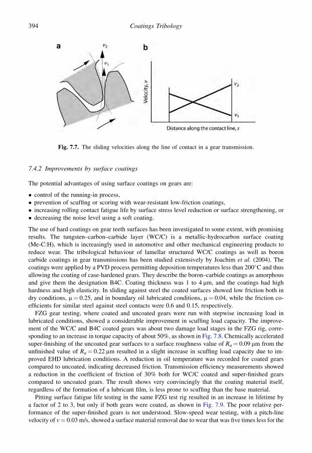
7.4.2 Improvements by surface coatings
The potential advantages of using surface coatings on gears are:
� control of the running-in process,� prevention of scuffing or scoring with wear-resistant low-friction coatings,� increasing rolling contact fatigue life by surface stress level reduction or surface strengthening, or� decreasing the noise level using a soft coating.
The use of hard coatings on gear teeth surfaces has been investigated to some extent, with promisingresults. The tungsten–carbon–carbide layer (WC/C) is a metallic-hydrocarbon surface coating(Me-C:H), which is increasingly used in automotive and other mechanical engineering products toreduce wear. The tribological behaviour of lamellar structured WC/C coatings as well as boroncarbide coatings in gear transmissions has been studied extensively by Joachim et al. (2004). Thecoatings were applied by a PVD process permitting deposition temperatures less than 200�C and thusallowing the coating of case-hardened gears. They describe the boron–carbide coatings as amorphousand give them the designation B4C. Coating thickness was 1 to 4 mm, and the coatings had highhardness and high elasticity. In sliding against steel the coated surfaces showed low friction both indry conditions, m¼ 0.25, and in boundary oil lubricated conditions, m¼ 0.04, while the friction co-efficients for similar steel against steel contacts were 0.6 and 0.15, respectively.
FZG gear testing, where coated and uncoated gears were run with stepwise increasing load inlubricated conditions, showed a considerable improvement in scuffing load capacity. The improve-ment of the WC/C and B4C coated gears was about two damage load stages in the FZG rig, corre-sponding to an increase in torque capacity of about 50%, as shown in Fig. 7.8. Chemically acceleratedsuper-finishing of the uncoated gear surfaces to a surface roughness value of Ra¼ 0.09 mm from theunfinished value of Ra¼ 0.22 mm resulted in a slight increase in scuffing load capacity due to im-proved EHD lubrication conditions. A reduction in oil temperature was recorded for coated gearscompared to uncoated, indicating decreased friction. Transmission efficiency measurements showeda reduction in the coefficient of friction of 30% both for WC/C coated and super-finished gearscompared to uncoated gears. The result shows very convincingly that the coating material itself,regardless of the formation of a lubricant film, is less prone to scuffing than the base material.
Pitting surface fatigue life testing in the same FZG test rig resulted in an increase in lifetime bya factor of 2 to 3, but only if both gears were coated, as shown in Fig. 7.9. The poor relative per-formance of the super-finished gears is not understood. Slow-speed wear testing, with a pitch-linevelocity of v¼ 0.03 m/s, showed a surface material removal due to wear that was five times less for the
Fig. 7.7. The sliding velocities along the line of contact in a gear transmission.
394 Coatings Tribology

coated gears compared to the uncoated. Interestingly, simply coating one of the contacting gears wassufficient for the wear reduction and coating both gears did not result in any further improvement. Thewide range investigation by Joachim et al. (2004) shows that hard coatings can improve the scuffing,pitting and slow-speed wear resistance as well as reduce the friction in gear contacts and transmissionsconsiderably. However, the tribological contact conditions in various transmission applications varyand thus are expected to result in a fairly large scatter in the tribological effect of coatings on gears.
In gear tests metal-containing carbon-based coatings on spur gears resulted in a sixfold increase inwear life, reported by Krantz et al. (2003).
A marked increase in scuffing wear resistance and a higher load-carrying capacity were also ob-served by Douglas et al. (1987) for cathodic arc PVD titanium nitride coated gears compared touncoated standard gears (DIN 17210), tested in an FZG power circuit and a Ryder gear testing ma-chine. The TiN coating was approximately 3 mm thick at the tips of the teeth and tapered down to 1 mmat the tooth roots. Light scratches occurred on the standard gear surfaces at the third load stage andscuffing failure at the seventh load stage in the FZG test with a pinion speed of 1500 rpm. In the sameconditions the TiN coated gears succeeded without scuffing failure in all 12 load steps with the coatingintact and only minimal subsurface plastic deformation.
In dry running back-to-back gear testing Mao et al. (2007) found that TiN coated gears reduced thegear wear weight loss to less than half compared with uncoated gears while plasma-nitrided gears
Fig. 7.8. Scuffing load capacity shown as scuffing load stage of uncoated, WC/C coated, B4C coated andsuper-finished gears in FZG scuffing test with oil lubrication (data from Joachim et al., 2004).
Fig. 7.9. Macropitting lifetime of uncoated, WC/C coated, B4C coated and super-finished gears in FZGpitting test with oil lubrication (data from Joachim et al., 2004).
395Applications

reduced it to one-tenth and duplex coated gears, with TiN on a plasma-nitrided surface, reduced it50 times. The gears were run at 500 rev/min at a load of 40 Nm for periods of 3000 cycles. The duplextreatment of gears is certainly expensive but can considerably improve the wear performance in dryrunning conditions.
In a high-speed power circuit gear test machine, Terauchi et al. (1987) recorded improved scoringresistance of gears with a titanium nitride and a titanium carbide coated gear wheel running against anuncoated pinion of case-hardened chromium–molybdenum steel (SCM415H). The TiC was depositedby the CVD process and the TiN by PVD and the coating thickness was approximately 2 mm. In thesetests the rotational speed of the pinion was first increased stepwise from 2000 to 10,372 rpm (fromstart-up to 45 MJ/mm in Fig. 7.10), with a constant load of 266 N/mm. The load was then increasedstepwise from 266 to 390 N/mm (from 45 MJ/mm forward in Fig. 7.10) with a constant rotationalspeed of 10,372 rpm. Figure 7.10 shows that the best compromise between scoring resistance and lownoise level was achieved with a TiN coated wheel against an uncoated pinion (UN). Improved scoringresistance, but at higher noise levels, was recorded for a TiC coated wheel against an uncoated pinion(UC) compared to the uncoated gear pair (U). Early failure by abrasive wear was observed for a TiNcoated pinion against an uncoated wheel (NU) and for TiN coated gear pairs (N). This is not consistentwith the good results from gear tests with TiN coated gears by Douglas et al. (1987) referred to earlier.It may have been due to unsatisfactory running-in of the gear surfaces.
Significant improvements in the scoring resistance of spur gears can be achieved by using copperplating or molybdenum disulphide coatings on the gears. Also graphite coatings have been found to beeffective in increasing scoring and wear resistance (Terauchi et al., 1986a; Field et al., 2004). In anexperimental study with a power circuit gear test machine, Terauchi et al. (1984) found that a 20 mmthick copper coating on the gears decreased the sound level by 7 dB and the best scoring resistancewas achieved when both pinion and wheel were copper plated followed by the combination ofunplated pinion and plated wheel. The test gears were made from chrome–molybdenum steel(SCM420H), had a roughness of Rmax¼ 2.4 mm before copper plating and were lubricated bya straight mineral oil without additives.
Fig. 7.10. Variation of noise from the gear tooth contact as a function of cumulative transmitted work perunit face width with the failure indicated by a vertical arrow. U stands for uncoated, N for TiN coated andC for TiC coated (data from Terauchi et al., 1987).
396 Coatings Tribology

Scuffing FZG gear tests carried out in additive-free oil lubricated conditions by Amaro et al. (2005)of MoS2/titanium coated gears showed a very significant increase of the load-carrying capacityagainst the scuffing load correlating to 40% increased power transmission capacity at 1500 rev/minand 77% at 3000 rev/min rotational speed. The gearbox efficiency was improved 0.5% at high torqueand low speed. The MoS2/Ti coating was deposited by DC magnetron sputtering; it has a multilateredstructure and a thickness of only 1.2 mm.
Gear tests with a 10 mm thick MoS2 coating on the gears showed a significant increase in thescoring resistance but the effect of the MoS2 film on seizure load was small (Terauchi et al., 1986b).A significant improvement in scuffing load capacity has been reported when using multilayercomposite MoS2/Ti and C/Cr coatings on C-type gears in the FZG gear test rig (Martins et al., 2008).The MoS2/Ti coated gears increased the transfer gearbox’s efficiency by 0.5%.
7.5 Tools for Cutting
7.5.1 Description of the application
Cutting of metals and other engineering materials has been and still is the major shaping process usedin the production of engineering components. Even though new advanced manufacturing methods arebeing developed all the time, up to now no serious challenger has emerged that could replace cuttingas the main shaping process within the next few decades.
This application is discussed in detail for two reasons. The first is that the tribological contact incutting differs considerably from the general sliding or rolling contacts discussed earlier. The secondis that cutting tools were the first successful commercial tribological application of thin surfacecoatings.
Even if the cost of consumable cutting tools is relatively low they have a remarkable influence onproductivity and manufacturing costs. The material removal rate is very much determined by thetribological factors which dictate how fast a cutting tool can be moved through the material rather thanother factors such as machine limitations. When a cutting tool wears out the operation is interrupted
Fig. 7.11. Schematic illustration of the cutting process.
397Applications
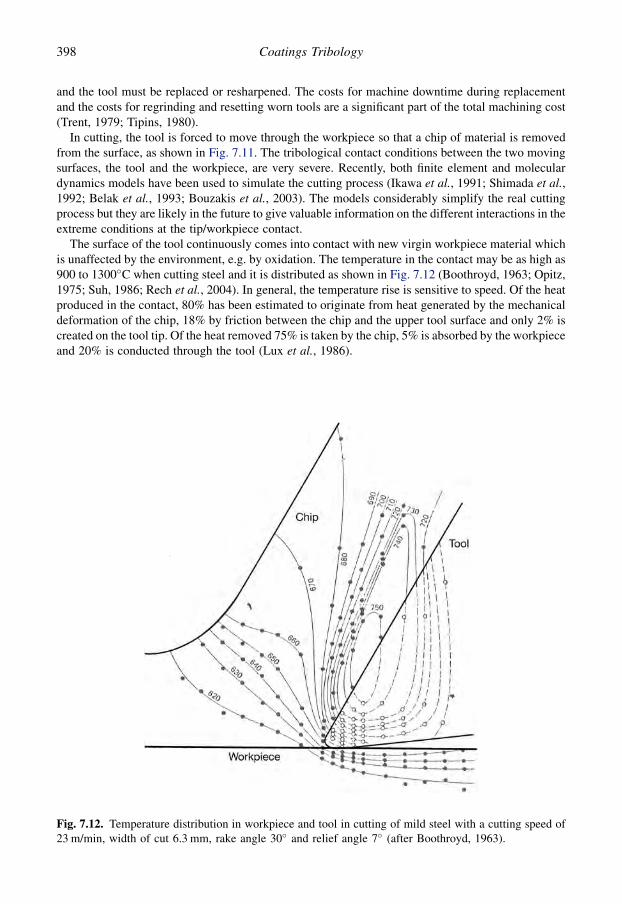
and the tool must be replaced or resharpened. The costs for machine downtime during replacementand the costs for regrinding and resetting worn tools are a significant part of the total machining cost(Trent, 1979; Tipins, 1980).
In cutting, the tool is forced to move through the workpiece so that a chip of material is removedfrom the surface, as shown in Fig. 7.11. The tribological contact conditions between the two movingsurfaces, the tool and the workpiece, are very severe. Recently, both finite element and moleculardynamics models have been used to simulate the cutting process (Ikawa et al., 1991; Shimada et al.,1992; Belak et al., 1993; Bouzakis et al., 2003). The models considerably simplify the real cuttingprocess but they are likely in the future to give valuable information on the different interactions in theextreme conditions at the tip/workpiece contact.
The surface of the tool continuously comes into contact with new virgin workpiece material whichis unaffected by the environment, e.g. by oxidation. The temperature in the contact may be as high as900 to 1300�C when cutting steel and it is distributed as shown in Fig. 7.12 (Boothroyd, 1963; Opitz,1975; Suh, 1986; Rech et al., 2004). In general, the temperature rise is sensitive to speed. Of the heatproduced in the contact, 80% has been estimated to originate from heat generated by the mechanicaldeformation of the chip, 18% by friction between the chip and the upper tool surface and only 2% iscreated on the tool tip. Of the heat removed 75% is taken by the chip, 5% is absorbed by the workpieceand 20% is conducted through the tool (Lux et al., 1986).
Fig. 7.12. Temperature distribution in workpiece and tool in cutting of mild steel with a cutting speed of23 m/min, width of cut 6.3 mm, rake angle 30� and relief angle 7� (after Boothroyd, 1963).
398 Coatings Tribology

The normal pressure on the rake face is very high and can be up to 1200 MPa when cutting steel.For tools of the same geometry the compressive stress on the tool is related to the yield stress of thework material (Trent, 1979). The distribution of the normal and the shear stress is shown in Fig. 7.13.
The coefficient of friction between the chip and the tool is influenced by factors such as cuttingspeed, feed rate, rake angle, etc. It has been observed to vary considerably, mainly because of the veryhigh normal pressure at the surface. This can cause the real area of contact to approach the apparentarea of contact over part of the tool/chip contact (Moore, 1975; Grzesik, 2000; Childs, 2006). Thetool/workpiece contact friction is higher than the tool/chip friction and the frictional behaviour hasbeen shown to be adhesion related (Chandrasekaran, 1976).
7.5.2 Tool wear
Four main mechanisms of tool wear have been identified, namely adhesive wear, abrasive wear,delamination wear and wear due to chemical instability, including diffusion, solution and electro-chemical wear as shown in Fig. 7.14.
Adhesive wear is caused by the formation of welded asperity junctions between the chip and thetool faces and the fracture of the junctions by the shearing force so that tiny fragments of the toolmaterial are torn out and adhere to the chip or the workpiece (Moore, 1975). This kind of wear mayoccur at the flank face in low-speed cutting when the contact temperatures are not so high. It mayinvolve oxidation of the tool surface, or other chemical interaction with the surrounding atmosphere,followed by mechanical removal of the products of the reaction (Trent, 1979; Suh, 1986; Thangarajand Weinmann, 1992).
Abrasive wear on the tool surfaces is caused by hard particles in the work material. Their effect onthe tool wear can be explained theoretically by three abrasion models, these are microploughing,microchipping and microcracking (Knotek et al., 1993). Many work materials, e.g. cast iron and steel,contain particles of phases which have a hardness that is much higher than that of the workpiece. Theparticles can typically be carbides or oxides, particularly Al2O3, but also silica and some silicates(Trent, 1979).
The particles may also be highly strain-hardened fragments from an unstable built-up edge on thetool (Moore, 1975). In particular, the wear at the flank face may be attributed to abrasive wear. Inabrasive wear the influence of tool surface hardness is considerable (Budinski, 1980; Kramer, 1986;Konig and Kammermeier, 1992).
Fig. 7.13. Tool stress distributions in the chip/tool interface (after Moore, 1975).
399Applications
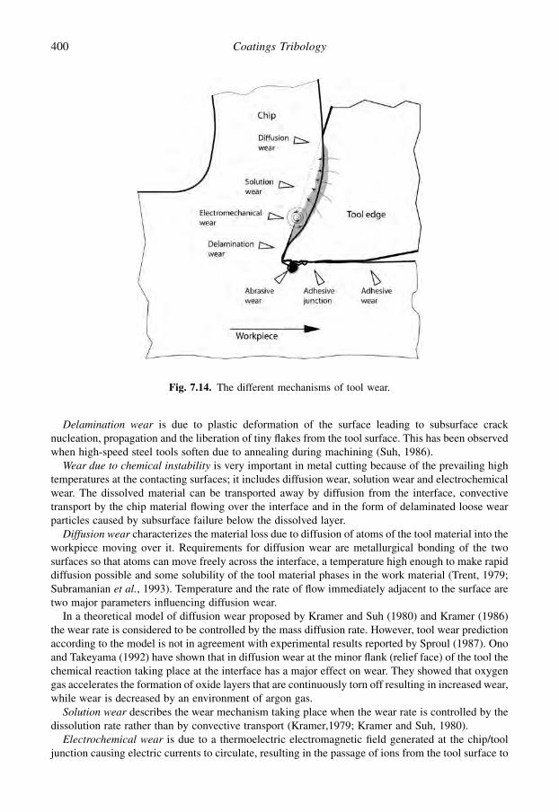
Delamination wear is due to plastic deformation of the surface leading to subsurface cracknucleation, propagation and the liberation of tiny flakes from the tool surface. This has been observedwhen high-speed steel tools soften due to annealing during machining (Suh, 1986).
Wear due to chemical instability is very important in metal cutting because of the prevailing hightemperatures at the contacting surfaces; it includes diffusion wear, solution wear and electrochemicalwear. The dissolved material can be transported away by diffusion from the interface, convectivetransport by the chip material flowing over the interface and in the form of delaminated loose wearparticles caused by subsurface failure below the dissolved layer.
Diffusion wear characterizes the material loss due to diffusion of atoms of the tool material into theworkpiece moving over it. Requirements for diffusion wear are metallurgical bonding of the twosurfaces so that atoms can move freely across the interface, a temperature high enough to make rapiddiffusion possible and some solubility of the tool material phases in the work material (Trent, 1979;Subramanian et al., 1993). Temperature and the rate of flow immediately adjacent to the surface aretwo major parameters influencing diffusion wear.
In a theoretical model of diffusion wear proposed by Kramer and Suh (1980) and Kramer (1986)the wear rate is considered to be controlled by the mass diffusion rate. However, tool wear predictionaccording to the model is not in agreement with experimental results reported by Sproul (1987). Onoand Takeyama (1992) have shown that in diffusion wear at the minor flank (relief face) of the tool thechemical reaction taking place at the interface has a major effect on wear. They showed that oxygengas accelerates the formation of oxide layers that are continuously torn off resulting in increased wear,while wear is decreased by an environment of argon gas.
Solution wear describes the wear mechanism taking place when the wear rate is controlled by thedissolution rate rather than by convective transport (Kramer,1979; Kramer and Suh, 1980).
Electrochemical wear is due to a thermoelectric electromagnetic field generated at the chip/tooljunction causing electric currents to circulate, resulting in the passage of ions from the tool surface to
Fig. 7.14. The different mechanisms of tool wear.
400 Coatings Tribology

the workpiece material. This may result in breakdown of the tool material and scaling of the toolsurface at the tool/chip interface (Moore, 1975). The thermoelectric current is formed at the chip/crater contact and at the flank/workpiece contact and its intensity has been found to be as high as 5 Awith the tool being of negative polarity (Opitz, 1975; Shan and Pandey, 1980; Uehara et al., 1992).
As shown in Fig. 7.15, for a given workpiece material, abrasive wear occurs under all cuttingconditions to approximately the same extent while adhesive wear is found mainly at low cuttingtemperatures, corresponding to low cutting speeds. Wear due to chemical instability, including effectslike diffusion and oxidation appears at high cutting speeds (Konig, 1984; Knotek et al., 1993).
Flank wear at the front edge of the tool flank and crater wear at the tool face, as shown in Fig. 7.16,are the most typical modes of tool wear in metal cutting. Flank wear is believed to be caused mainlyby abrasion of the tool by hard particles but there may also be adhesive effects. It is the dominatingwear mode at low cutting speeds (Thangaraj and Weinmann, 1992; Schmid and Wilson, 2001).Mapping of wear data for flank wear of high-speed steel cutting tools in turning, as a function of feedrate and cutting speed, shows that by suitable choice of cutting parameters a safety zone with low wearcan be reached (Lim et al., 1993b).
Crater wear is the formation of a groove or a crater on the tool face, typically some 0.2 to 0.5 mmfrom the cutting edge, at the place where the chip moves over the tool surface, as shown in Fig. 7.16b.It is very commonly observed when cutting high melting point metals like steel at relatively highcutting speeds. Crater wear is caused primarily by the dissolution of tool material by diffusion orsolution wear since it occurs in the region of maximum temperature rise, as shown in Fig. 7.12(Subramanian et al., 1993).
Two other mechanisms for tool failure, which do not include wear, are fracture of the tool andplastic deformation of the tool edge. Because of the high hardness and brittleness, as well as thesharp edges of the tool, fracture occasionally occurs. The high pressure and temperature nearthe tool edge may cause plastic deformation and initiate the wear process (Trent, 1979; Suh, 1986).A wear map for uncoated high-speed steel cutting tools with feed rate and cutting speed as co-ordinate axes and showing the transition from one wear mechanism to another has been publishedby Lim et al. (1993a).
A built-up edge of piled-up work material near the tip of the cutting edge is frequently formed atintermediate cutting speeds, as shown in Fig. 7.16a. This typically occurs when cutting alloys that
Fig. 7.15. Schematic diagram of tool wear mechanisms appearing at different cutting temperaturescorresponding to cutting speed and feed (after Konig, 1984).
401Applications

contain more than one phase, like carbon steel, cast iron and alpha–beta brass. As the first layer ofwork material that adheres to the tool tip is considerably strengthened by the shear strain, yield willoccur in less-strained layers further from the tool surface. A continuous repetition of this processresults in agglomerates that form relatively large layers of work-hardened material that accumulate toform a built-up edge (Trent, 1979; Suh, 1986).
The built-up edge is often unstable; it breaks away intermittently and is formed again. Dependingon the materials and the cutting conditions the influence of the built-up edge may sometimes decreaseor at other times increase the tool life. A stable built-up edge can be very beneficial and protect the toolsurface from wear. On the other hand, loose highly strain-hardened fragments of the built-up edgemay adhere to the chip or workpiece and cause abrasion of the tool. At higher cutting speeds a built-upedge is less likely to form because the temperature increases and the built-up edge can no longersupport the stress of cutting and will thus be replaced by a flow zone.
Cutting fluids are used for both cooling and lubrication. Cooling is important at cutting speedsabove 60 m/min, for the reduction of chip/tool temperatures thereby reducing crater wear, which isstrongly temperature sensitive (Tipins, 1980). The effect of lubrication between chip and tool is mostpronounced at cutting speeds below 15 m/min reducing chip compression, built-up edge formation,cutting forces and power consumption (De Chiffre, 1990). At cutting speeds greater than 10 m/min,for steels, local thermal softening of chip material due to friction heating results in a degree of self-lubrication. Some steels, such as free-machining and calcium treated steels, contain solid lubricantinclusions that can segregate on the rake face to reduce friction (Childs, 2006).
The mechanism of lubrication between chip and tool at the rake face has long been a contentiousissue. A considerable effect of the cutting fluid is easily observed but it is difficult to explain how thelubricant can get into the contact area, characterized by high-temperature flow between chip and tool
Fig. 7.16. Typical location of wear failure and built-up edge on the tool.
402 Coatings Tribology

which follows immediately after the virgin chip surface has been produced. De Chiffre (1977, 1990)explains the lubricant action on the basis of a contact length approach which does not require any fluidaccess to the chip/tool interface. Over a distance from the cutting edge, intimate contact and fulladhesion exist between chip material and tool. The cutting fluid, however, prevents further growth ofthe adhesion area, with the result of reducing the length of the contact as compared to dry cutting. Theshorter contact length then reduces the frictional drag, and this in turn reduces the deformation work.Because the apparent area of contact is almost the same as the real area of contact, the contact lengthwill be directly related to the friction force.
The reduction of the chip/tool contact length L is expected to occur due to the synergistic effect ofthe following three mechanisms (De Chiffre, 1988a, b, 1990), as shown in Fig. 7.17:
1. Contamination, or rather boundary lubrication, of the rake face at A. Adhesion of the virgin chipsurface on to the tool is inhibited in the region far away from the cutting edge.
2. Chip curl promotion at B, due to the Rehbinder effect at low speeds and cooling at high speeds.3. Overall reduction of the cutting temperature by cooling, lowering the adhesion tendency and
promoting contact area restriction.
A similar reduction in the contact area on the rake face with TiN coated tools compared to uncoatedhas been observed by Posti and Nieminen (1989a). Here the solid coating acts as a lubricating surfaceby inhibiting adhesion.
Wear is almost always reduced by the use of cutting fluids, with some exceptions when it maypromote thermal cracking, hardening of work material through quenching and embrittlement of toolsby chemical or physical attack (Tipins, 1980).
7.5.3 Improvements by surface coatings
Improved performance of cutting tools to give lower wear, lower friction and extended tool lifetimecan be achieved by depositing hard coatings on the tool surface. The main favourable effects fromusing coatings come from:
� the reduced friction resulting in lower heat generation and lower cutting forces,� reduced adhesion to the workpiece resulting in less material transfer from the tool surface,� increased hardness of the surface resulting in reduced abrasive wear, and� reduced diffusion due to the improved diffusion barrier and chemical stability properties of the
coating.
Fig. 7.17. Illustration of the contact length reduction theory by De Chiffre (1990). L is length of contactbetween chip and tool face, A and B are referred to in the text.
403Applications

Thus to be successful the coating material should exhibit the following characteristics:
� low adhesion to the workpiece material,� high adhesion to the tool material,� good abrasive wear resistance,� high chemical stability, and� high toughness.
Thin hard coatings of nitrides or carbides match these requirements well and have been used suc-cessfully resulting in increased tool lifetime of 30% to up to 200-fold. Their small thickness givesthem the high degree of elasticity needed for absorbing impacts and the high tool edge stresses. At thesame time they also influence the basic cutting parameters like chip flow, chip form, cutting edgetemperature and optimum working range. The tool thus needs to be reoptimized with respect tocutting edge angles, clearance angles, steel quality, hardness, roughness, etc. Successful applicationsof the use of hard coatings on tools has been reported for machining operations like turning, profiling,grooving, threading, drilling, tapping, reaming, broaching, milling and hobbing; and with workpiecematerials like carbon steels, alloy steels, cast iron, stainless steels, superalloys, aluminium alloys andtitanium alloys (Sudarshan, 1992; Gunther et al., 1989; Vogel, 1989; Quinto, 1996, 2007; Dearnley,2006; Veprek and Veprek-Heijman, 2008).
The better tribological performance of coated cutting tools results in advantages like:
� reduced tool costs per component due to the extended tool lifetime,� reduced downtime costs,� increased productivity because faster cutting speeds can be used due to lower friction, which also
reduces machine power consumption, and� improved workpiece quality in the form of better surface finish due to improved lubricity and other
effects such as improved dimensional accuracy in cutting.
7.5.3.1 Substrate materials
High-speed steel and cemented carbide are commonly used substrate materials for thin and hard PVDcoatings (Hintermann, 1983a; Larsson, 1996; Grzesik, 2000). The powder metallurgy grades of high-speed steel are particularly useful, since their good carbide distribution ensures consistent quality andcan even enhance adhesion due to the good lattice match between the carbides and TiN.
7.5.3.2 Wear mechanisms
Depending on the cutting conditions one or more of the wear mechanisms shown in Fig. 7.14 willdominate the wear process and thus be the limitation for the tool lifetime. If abrasive wear dominates,the hardness of the coating is important; if adhesive wear dominates, low adhesion to the workmaterial is important; and if wear due to chemical instability dominates diffusion isolation or lowsolution properties of the coating are important.
Coating fracture and failure can result if the coating is too hard and thick in relation to the elasticityof the substrate or if the substrate beneath the coating is softened by the high temperatures. Thedeflection creates high stresses within the coating that may lead to fracture (Billgren, 1984). Thismechanism has been observed to be the main cause of failure for nitride and carbide coatings on high-speed steel cutting tool inserts by Fenske et al. (1988) and is illustrated in Fig. 7.18. This is in line withthe scratch test study by Hedenqvist et al. (1990b) where they described in detail 12 differentmechanisms of coating fracture and damage partly due to substrate deformation. The very favourableproperties of TiN and TiC coated HSS inserts in relation to the adhesive, abrasive and solution wearmechanisms have been shown by Billgren (1984) and Hedenqvist et al. (1990b).
404 Coatings Tribology

7.5.4 Cutting test results
7.5.4.1 Turning tools
Considerable increases in tool lifetime have been attained with high-speed steel inserts coated withnitride or carbide coatings. The lifetime has been reported to increase by 2 to 10 times compared touncoated tools (Bruno et al., 1988; Kowstubhan and Philip, 1991). In lifetime comparisons Sproul(1987) found that TiN sputter coated inserts, with a coating thickness of 5 mm, have a longer lifetimethan TiC, ZrC, HfC, ZrN or HfN coated inserts, as shown in Fig. 7.19. The results from turning testsby Harju et al. (1990) show that ion-plated TiN coated inserts, with a coating thickness of 1.5 to3.5 mm, are superior to ZrN and HfN coated inserts. For TiN coatings longer lifetimes have beenobserved for coatings with thicknesses in the range of 5 to 6 mm compared to thinner coatings in therange 0.5 to 3.5 mm, as shown in Fig. 7.20.
Ronkainen et al. (1991a, b) and Knotek et al. (1992c, f) have shown that in turning tests ion-plated(Ti,Al)N and (Ti,V)N coatings improve the wear resistance considerably and give lifetimes two tothree times better than TiN coatings; however, no major improvement was observed with Ti(B,N).Inserts coated by TiHfN, 2.5 mm thick, and TiNbN, 4.9 mm thick, have shown an improved crater wearresistance in cutting tests, compared to TiN coatings, but the flank wear increased (Boelens andVeltrop, 1987). A reduction in machining costs when using cBN–TiN composite carbide coatedinserts for hard turning applications has been shown by cost analysis (More et al., 2006). CVD coatedAl2O3 inserts have a very similar wear behaviour compared to TiN coated inserts and no significantdifferences have been observed (Schintlmeister et al., 1978).
Fig. 7.18. Schematic diagram of the coating wear process at (a) the initial stage, (b) the substrate soft-ening and coating fracture stage and (c) the failure stage, observed for nitride and carbide coated high-speed steel cutting tool inserts during dry cutting of 1045 steel at surface speeds of 100 m/min (afterFenske et al., 1988).
405Applications

The use of hard coatings on cutting tools often gives a better surface finish on the workpiece but theperformance of the tool may decrease after resharpening, depending of the type on wear and regroundface (Vogel, 1989).
Diamond coatings have been successfully used for machining of high silicone content aluminiumalloys for automotive applications. The major applications for Al–Si alloys are pistons, engine blocksand heads, wheels and chassis, and some transmission parts (Erdemir and Donnet, 2001). Theincreased use of lightweight materials in the automotive industry is likely to continue and the need fordiamond coated tools will increase.
In the machining of aluminium, aluminium–silicon alloys, copper, graphite and other non-ferrousmaterials, CVD diamond coated inserts have given lifetimes 3 to 20 times longer than cemented
Fig. 7.19. Time to failure of coated and uncoated high-speed steel tool inserts, in turning tests with (a)cutting fluid and hard work material and (b) with no cutting fluid and soft work material according to datafrom Sproul (1987).
406 Coatings Tribology

carbide, silicon nitride or sintered diamond inserts (Kikuchi et al., 1991; Soderberg et al., 1991; Yazuand Nakai, 1991; Lux and Haubner, 1992; Inspector et al., 1994; Quinto, 1996). Other materialssuitable for machining by diamond tools are magnesium, manganese, lead, as well as various com-posites, bulk graphite, plastics, epoxy resins, green ceramic and concrete. However, tool wear ofdiamond coated inserts is extremely rapid when machining ferrous materials because of the highchemical reactivity and the solubility of carbon in ferrous materials at elevated temperatures (Evans,1991; Soderberg, 1991).
7.5.4.2 Twist drills
Considerable lifetime improvements have been achieved by using twist drills coated with thin hardcoatings. Titanium nitride has again proved to be an excellent coating material on high-speed steeldrills (HMSO, 1986; Matthews, 1989; Monaghan et al., 1993; Goller et al., 1999; Cosemans et al.,2003). In a large drilling test comparison, twist drills with 2 to 3 mm thick PACVD coated TiN layershad on average an eightfold lifetime increase compared to uncoated drills (Shizhi et al., 1990). Theperformance of coated drills depends on the work material. Vogel (1989) has reported fourfoldlifetime improvements of TiN coated twist drills when drilling an unalloyed carbon, case-hardenedand tool steel, fivefold increases when drilling cast iron, non-ferrous metals and free-cutting steel, andninefold increases when drilling stainless steel. He also reports a 17% drop in the feed force andimproved cutting performance after resharpening of the drills. This can be explained by the main wearnot occurring on the primary flank but more on the lip and on the margin. Further lifetimeimprovements by 15 to 100% in drilling tests have been reported by Goller et al. (1999) and Cosemanset al. (2003) when incorporating a soft MoSx phase in the TiN matrix.
Drills coated with (Ti,Al)N perform, in general, even better than TiN coated ones, as shown inFig. 7.21. This has been attributed to the formation of a dense, highly adhesive, protective Al2O3
Fig. 7.20. Tool lifetime in turning tests of TiN coated ASP 30 tools as a function of the coating thicknesson the flank face (data from Posti and Nieminen, 1989b).
407Applications
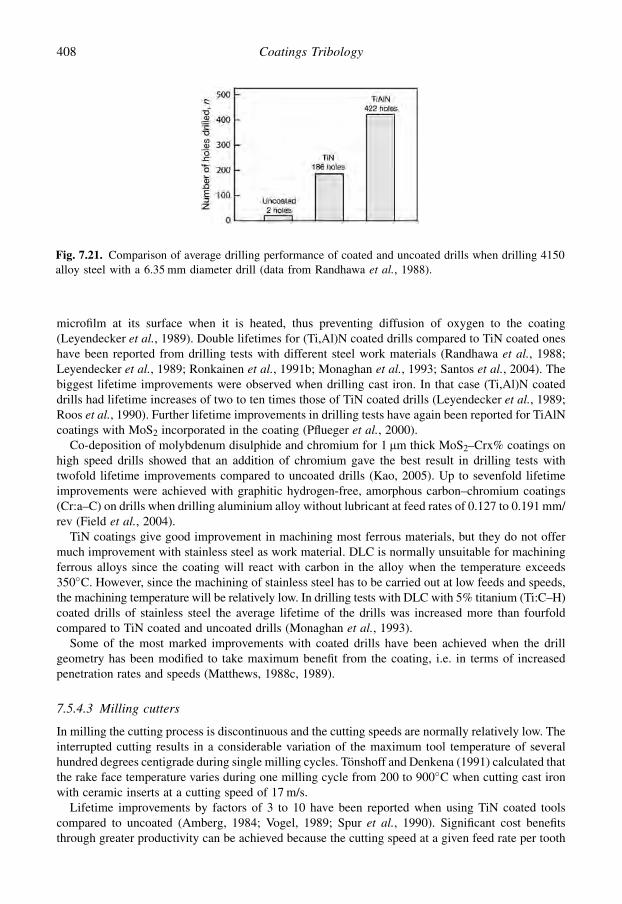
microfilm at its surface when it is heated, thus preventing diffusion of oxygen to the coating(Leyendecker et al., 1989). Double lifetimes for (Ti,Al)N coated drills compared to TiN coated oneshave been reported from drilling tests with different steel work materials (Randhawa et al., 1988;Leyendecker et al., 1989; Ronkainen et al., 1991b; Monaghan et al., 1993; Santos et al., 2004). Thebiggest lifetime improvements were observed when drilling cast iron. In that case (Ti,Al)N coateddrills had lifetime increases of two to ten times those of TiN coated drills (Leyendecker et al., 1989;Roos et al., 1990). Further lifetime improvements in drilling tests have again been reported for TiAlNcoatings with MoS2 incorporated in the coating (Pflueger et al., 2000).
Co-deposition of molybdenum disulphide and chromium for 1 mm thick MoS2–Crx% coatings onhigh speed drills showed that an addition of chromium gave the best result in drilling tests withtwofold lifetime improvements compared to uncoated drills (Kao, 2005). Up to sevenfold lifetimeimprovements were achieved with graphitic hydrogen-free, amorphous carbon–chromium coatings(Cr:a–C) on drills when drilling aluminium alloy without lubricant at feed rates of 0.127 to 0.191 mm/rev (Field et al., 2004).
TiN coatings give good improvement in machining most ferrous materials, but they do not offermuch improvement with stainless steel as work material. DLC is normally unsuitable for machiningferrous alloys since the coating will react with carbon in the alloy when the temperature exceeds350�C. However, since the machining of stainless steel has to be carried out at low feeds and speeds,the machining temperature will be relatively low. In drilling tests with DLC with 5% titanium (Ti:C–H)coated drills of stainless steel the average lifetime of the drills was increased more than fourfoldcompared to TiN coated and uncoated drills (Monaghan et al., 1993).
Some of the most marked improvements with coated drills have been achieved when the drillgeometry has been modified to take maximum benefit from the coating, i.e. in terms of increasedpenetration rates and speeds (Matthews, 1988c, 1989).
7.5.4.3 Milling cutters
In milling the cutting process is discontinuous and the cutting speeds are normally relatively low. Theinterrupted cutting results in a considerable variation of the maximum tool temperature of severalhundred degrees centigrade during single milling cycles. Tonshoff and Denkena (1991) calculated thatthe rake face temperature varies during one milling cycle from 200 to 900�C when cutting cast ironwith ceramic inserts at a cutting speed of 17 m/s.
Lifetime improvements by factors of 3 to 10 have been reported when using TiN coated toolscompared to uncoated (Amberg, 1984; Vogel, 1989; Spur et al., 1990). Significant cost benefitsthrough greater productivity can be achieved because the cutting speed at a given feed rate per tooth
Fig. 7.21. Comparison of average drilling performance of coated and uncoated drills when drilling 4150alloy steel with a 6.35 mm diameter drill (data from Randhawa et al., 1988).
408 Coatings Tribology

can be doubled by using TiN coated tools. Full performance is achieved even after regrinding becauseno crater wear occurs at the cutting speeds normally used. The main wear mechanism is a continuousgrowth of flank wear by adhesion. As the cutting time increases, fracture of the coating at the rake faceof the tool may take place, as shown in Fig. 7.22. This has been observed by Spur et al. (1990) whenmilling ductile materials by PVD TiN coated HSS indexible inserts. The result is a kind of self-sharpening effect.
Interestingly, similar phenomena have been observed for cutting blades such as knives by Matthewsand Leyland (1990) and for metal stamping tools by Franklin (1990).
The lifetime of milling tools is greatly improved by TiN coated tools both in dry cutting and witha cutting fluid, as shown in Fig. 7.23. In steel milling tests Konig et al. (1992) found that the im-provement of tool lifetime is slightly less with (Ti,Al)N coated tools compared to TiN coated ones,while Ti(C,N) coated tools showed the best wear resistance and had a lifetime three times longer thanthe TiN coated tools. Coating thicknesses in the range of 2 to 10 mm were investigated by Bouzakiset al. (2003) and they found the best performance in milling tests for relatively thick (Ti46Al54)Ncoatings with coating thicknesses of over 6 mm. Nordin (2000) found an up to 30% improvement inlifetime with TiN/TaN mulilayer coated tools compared to TiN coated.
Fig. 7.22. Mechanisms of tool wear that results in self-resharpening when milling ductile materials withTiN coated inserts (after Spur et al., 1990).
409Applications

For machining of non-ferrous materials such as aluminium, aluminium–silicon and copper alloys,graphite and calcium silicate, tool lifetime improvements of two- to 18-fold have been reported whenusing CVD diamond coated tools compared to cemented carbide inserts (McCune et al., 1989;Soderberg, 1991; Lux and Haubner, 1992; Quinto, 1996). The highest level of lifetime improvementwas observed by Kikuchi et al. (1991) in face milling of Al–12%Si cylinder heads of automobileengines, when the CVD diamond coated cemented carbide tools had an 18-fold lifetime compared touncoated. Quinto (2007) has presented the graphical representation shown in Fig. 7.24 illustratinghow coatings for milling cutters should be selected for the workpiece material, taking account of thecutting speed and force.
7.5.4.4 Gear cutting tools
Titanium nitride coatings have been very successful for gear cutting tools. This is, to a great extent,because higher cutting speeds, over 120 m/s, can be used with coated tools. Lifetime improvementsby factors of 3 to 8 for TiN coated tools (Vogel, 1989) and factors of 5 to 8 at double productivity, interms of cutting speed and feed, have been reported for (Ti,Al)N (Zlatanovic and Munz, 1990). Theuse of increased cutting speeds changes the dominating wear mechanism from flank wear to craterwear. This results in a decreased lifetime improvement after resharpening of the tools. When theinitial lifetime improvement for TiN coated tools has been observed to be 6 to 8 times, the im-provement was on average only three times after resharpening of the tools (Vogel, 1989). A reviewof gear hob improvements by coatings was given in Matthews (1989), and subsequent reports haveindicated steadily increasing performance, especially as the coating and gear producers work to-gether on optimizing geometries and coatings for particular workpiece materials, in parallel withmilling cutters.
Fig. 7.23. A comparison of tool life obtained with uncoated and TiN coated HSS inserts in milling ofa soft magnetic highly ductile material (Mumetal). Cutting distance to tool failure as a function of cuttingspeed for dry cutting and with cutting fluid (data from Spur et al., 1990).
410 Coatings Tribology

7.5.4.5 Taps and reamers
Lifetime improvements by a factor of 1.5 to 6 have been observed when using TiN coated taps orreamers. The cutting cannot be carried out at high speeds so no additional improvement in pro-ductivity is likely to be achieved. However, especially in tapping of mild steels, the coating reducescold welding, and in tapping of stainless steel the coating lowers the friction because the cutting forcesare better distributed over the cutting edge (Bruno et al., 1988; Vogel, 1989).
7.5.4.6 Wood cutting tools
The cutting conditions in wood and pulp product cutting are abrasive due to hard debris in the workmaterial. Early experiments showed that TiN on tungsten carbide tipped circular saws can reduce wearon the rake face by 50% when sawing hardboard (Osenius et al., 1987). No influence on wear wasrecorded when sawing particleboard, paperboard and plywood. Chrome nitride coating turned out toperform better in wood cutting compared to TiN, (Ti,Zr), Cr and W–C:H (DLC) (Djouadi et al., 1999).Very promising investigations have related to the use of different compositions of chrome nitride oftendeposited on nitrided surfaces to form a duplex coating (Djouadi et al., 2000; Chekour et al., 2003;Nouveau et al., 2001, 2003; Labidi et al., 2005).
Chromium nitride (CrxN) coating on nitrided low alloy steel knife surfaces resulting in a duplex-type surface gave an increase in lifetime of more than 2.5 times in accelerated wear tests cuttingmedium density fireboard (MDF), which is an abrasive and relatively homogeneous wood derivativematerial (Beer et al., 2003). One to 2 mm thick chromium and chromium nitride coatings have beenused in wood cutting in milling-type cutting tests (Noveau et al., 2005). A twofold lifetime increase intool life has been reported for ZrBN coated tools (Chala et al., 2005) and 2.5-fold lifetimeimprovements for ta-C and TiC/a-C DLC coated tools (Endler et al., 1999; Kaminski et al., 2005).
Fig. 7.24. Coating selection guide for milling cutters based on field performance and commercialacceptance. The multilayer versions are preferred in continuous cutting (Quinto, 2007, with permission).
411Applications

Table 7.1. Cutting tool improvements by hard coatings (mainly TiN). The data is collected from Hinterman (1983a), HMSO (1986), Fenske et al. (1988),Leyendecker et al. (1989), Posti and Nieminen (1989a, b), Vogel (1989), Matthews and Leyland (1990), Spur et al. (1990), Zlatanovic and Munz (1990),Konig et al. (1992), Monaghan et al. (1993), Goller et al. (1999), Pflueger et al. (2000), Cosemans et al. (2003), Field et al. (2004) and Kao (2005).
Extendedlifetime(times)
Surfacequality
Improvedcuttingperformance
Performance afterresharpening
Work material/Comments
1. Turning tools 2–10 Improved Increased cuttingspeed and feed
Decreased Steel.Aluminium: life-timetwofold for (Ti, Al)Ncompared to TiN.Non-ferrous: lifetime3–20-fold for diamondcompared to CC and SiN.
2. Twist drills 4–20 Significantly improved Drop in feed force.Increased cutting speed
Slight decrease Carbon, case-hardened,tool and stainless steels.Cast iron
3. Milling cutters 3–10 Improved Doubled cutting speeds Slight decrease Ductile magneticmaterials. Threefoldlonger lifetime for Ti(C, N)compared to TiN
4. Gear cutting tools 3–8 Improved Increased cutting speeds Decreased Carburizing steel5. Taps 4–10 Improved Increased cutting speeds Retained Carbon and stainless
steel. Cast iron6. Reamers 3–6 Improved Increased speed Improved Aluminium.
Carbon, stainless and highalloy tool steels.Cast iron
7. Counter bores,countersinks
2–10 Improved Increased speed Decreased Carbon and cast steel.Ni–Cr castings
8. Broaching tools 3 Significantly improved Increased speed Retained Steel9. Punching tools 3–100 Significantly improved Burring dramatically reduced Decreased Carbon steel.
Spring steel.Nickel, silver and Cu–Bebronze.Soft iron for magnets
10. Saws 20 Improved Reduced force Decreased Stainless steel.Ni alloys.Metal/plastic compounds
11. Knives, blades 2–500 Improved Improved Retained Fabrics, foods, wood
41
2C
oa
ting
sT
ribo
log
y

Significant improvements in wear resistance was reported for CVD diamond coated tools in millingtests and machining fibreboard and particleboard (Endler et al., 1999; Sheikh-Ahmad et al., 2003).
7.5.4.7 Other cutting tools
Improved lifetimes, typically by factors of 2 to 5, have been achieved with other tools, such as boringtools, die-sinks, broaches and punching tools. Extremely high lifetime improvements with TiN coatedtools have been reported for circular saws in cutting metal–plastic compounds with an extendedlifetime of 20-fold and for punches for battery case production of 100-fold (Hinterman, 1983a; Vogel,1989).
Knives are another important cutting application area for hard coatings. Matthews and Eskildsen(1993) report a 500-fold improvement in life between sharpening for a knife used for cutting multiplelayers of synthetic fabric, when coated with diamond-like carbon.
Matthews and Leyland (1990) achieved considerable improvements on knives used in the pack-aging industry by coating them on one side with hard metal carbide, nitride and boride compounds,such that the coating had a dense columnar structure. This morphology is beneficial with respect tosharpening since it encourages a clean coating fracture between columns as the blade wears or isreground, analogous to the effect shown in Fig. 7.22 for milling cutters.
This structure also results in the effective adhesion being enhanced by ensuring that the adhesivebond to the substrate is greater than the lateral cohesive strength within the coating. A similar effecthas been reported for turbine blade coatings (Fancey and Matthews, 1986; James and Matthews,1990).
A summary of improvements in cutting tools by the use of thin hard coatings is presented inTable 7.1.
7.6 Tools for Forming
7.6.1 Description of the application
Forming of a solid work material is achieved through major plastic deformation along the formingtool surface. The quality of forming and metal-working from tools, such as forming dies, punches androlls, is considerably influenced by the wear behaviour and the friction at the tool surface. The tri-bological situation is typically characterized by high surface pressures, low deformation velocities,sometimes high temperatures, and, depending on the lubrication, a variety of different friction con-ditions. Important criteria for tool material selection are a low tendency of adhesion to the workpiecein order to avoid adhesive tool wear and high hardness and sufficient toughness to avoid abrasive wear(HMSO, 1986; Matthes et al., 1990b; Schmid and Wilson, 2001). Unlike metal cutting, texturing ofthe tool surface is frequently used to minimize wear, control friction and stabilize the forming process(Groche and Kohler, 2006). Furthermore, coatings on the product, such as paints on sheet metal, canbe used to beneficially influence the tribological behaviour in the forming process.
7.6.2 Improvements by surface coatings
There are several published reports concerning major improvements in the lifetime of forming tools,with increases of up to 100 to 200 times, by the use of hard and thin surface coatings. However, veryfew of these articles describe and analyse in detail the tribological mechanisms involved, though it isobvious that the ability of the coating to decrease adhesion to the workpiece and to resist abrasive wearand galling are key parameters.
The selection of a proper tool coating to be used in metal forming depends greatly on the type ofmaterial to be formed. It is especially the resistance of the surface to galling that is critical. Podgornik
413Applications

et al. (2006b) studied PVD-deposited TiN, TiB2, VN, TaC and DLC coatings on cold work tool steelin a cold forming simulating load-scanning test against austenitic stainless steel and alloys of alu-minium and titanium. They found the following:
1. In the case of austenitic stainless steel, low friction materials, i.e. carbon-based coatings, give lowand stable friction and excellent protection against galling. At the same time polishing of thesurface reduces the probability of stainless steel transfer and improves the surface quality of theworkpiece.
2. For very soft metals with a high degree of plastic deformation during forming, such as aluminiumand aluminium alloys, nitrided forming tool steels and nitride-type coatings show a good resistanceagainst galling and a relatively stable friction. Similar results were observed for DLC coatedsurfaces.
3. Materials that show a high tendency for galling and transfer layer reception, i.e. titanium and ti-tanium alloys, started to adhere to the tool surface at very low loads, regardless of the coating used.Only plasma nitriding and VN coatings gave some improvement in galling performance ascompared to untreated steel. In this case, and in the case of aluminium alloys, polishing of the steelsurface, coated or uncoated, had practically no influence on the galling performance.
Drawing tools, dies and punches PVD coated with TiN, (Ti,Al)N, Ti(B,N) or TiB2 films withthicknesses of about 3 to 5 mm have been reported to achieve lifetime improvements by factors of 2 to10 (Sundquist et al., 1983; Straede, 1989; Vogel, 1989; Matthes et al., 1990b; Bhushan and Gupta,1991; Bjork et al., 2001; Klimek et al., 2003). For dies and punches, as well as for deep drawing tools,the use of 7 to 10 mm thick CVD-deposited TiC or TiN/TiC coatings has resulted in high lifetimeimprovement factors of 100 to 200 (Hintermann, 1979, 1983a; Bhushan and Gupta, 1991). Significantimprovements in tool life with DLC and MoS2:Ti coated tools in cold forming has also been reported(Field et al., 2004; Amaro et al., 2005).
It has been claimed to be more difficult to achieve lifetime improvements for forming toolsoperating in hot working conditions, according to work by Wiiala et al. (1987). In their simulatingwear test experiments the coefficient of friction at 20�C, 500�C and 900�C was slightly higher forboth TiN and TiAlN ion-plated tool material samples, compared to uncoated in both dry and lubri-cated conditions. Damage to the tool was initiated by cracking of the coatings, which immediatelyresulted in micro-pickup of work material along the cracks and the formation of large stronglyadherent friction welded regions.
Groche and Kohler (2006) cite four classes of tool coatings which can be beneficial for unlubricatedsheet forming: (1) sulphide/selenide films (e.g. MoS2), (2) carbon films (e.g. Me–C:H), (3) boron films(e.g. hexagonal BN) and (4) oxide films (e.g. WOx, Al2O3).
7.7 Erosion and Scratch Resistant Surfaces
7.7.1 Description of the application
There are many applications where surfaces are exposed to hard particles moving against andalongside the surface, resulting in plastic deformation and fracture of the surface seen as scratches,cracks, surface destruction and material removal. The particles may be carried by a gas or a liquid.The particle dimensions have a very large range, from large rocks in earth moving equipments tomicrosize particles bombarding optical instruments in space. In erosive wear, particles moving in gasor liquid bombard the surface and result in material removal, Fig. 3.1d. If the particles are pressedagainst the surface by another solid, three-body abrasive wear (see Fig. 3.11b) limits the endurancelife of, for example, excavators, transporters, transfer tubes for bulk transportation, pipelines, valves,
414 Coatings Tribology

fluidized bed combustion systems, aeroplane turbine engine components, optical lenses, spectacles,displays, car chassis, etc.
The basic tribological mechanisms of three-body abrasion and erosion are in many respects alikeand similar principal surface design solutions can often be applied. A commonly used relationship forerosion is that the erosion rate increases with increasing modulus of elasticity but decreases withincreasing hardness and increasing fracture toughness. The angle of impact has, however, a consid-erable influence. Ductile materials exhibit their maximum erosion rate at impact angles between 15�
and 30�, whereas brittle materials exhibit a continuously increasing erosion rate with increasingimpact angle and the maximum occurs at 90� (Hillery, 1986; Olsson et al., 1989; Hutchings, 1992;Davis, 2001).
7.7.2 Improvements by surface coatings
Thin hard coatings can be used on components for erosion and scratch protection. The impact angle aswell as the shape of the particles have an influence on what kind of surface layer provides gooderosion resistance. In general, harder and thicker coatings are more favourable at small impact angleswhere the wear mechanism is more abrasive.
Fatigue wear and brittle fracture dominate at impact angles close to 90�. If the impact mass is smalla thicker hard coating can give good protection, but if the impacts cause material deflection a brittlecoating may deflect, crack and fail. A thinner coating may, on the other hand, deflect with the substrateand provide scratch protection on the surface while the elastic substrate absorbs the impact energy.
The shape of the particles may also influence wear properties. Burnett and Rickerby (1988) showedthat 10 mm thick PVD TiN coatings are more resistant to angular particle erosion while 3 mm thick TiNcoatings have longer lifetimes when exposed to blunt particles.
7.7.2.1 Coated steel and ceramic surfaces
Hard surface coatings can offer good abrasive particle wear protection of steel surfaces. However,a direct correlation between the coating hardness and wear rate was not found in three-body TiO2
particle abrasive wheel testing carried out by Van Acker and Vercammen (2004), except for verysimilar diamond-like carbon coatings, as seen in Fig. 4.86. The hard TiN, CrN, TiCN and DLCcoatings had 25 to 200 times lower wear compared to the uncoated steel substrate and a hard chro-mium surface, while the lowest wear was measured for the hard DLC coating. A soft DLC coatingshowed very high wear, three times more than the uncoated steel surface.
It has been predicted and experimentally demonstrated that the optimum solution to abrasive anderosive wear problems might be in multilayered coatings such as a PVD titanium/titanium nitride(Matthews, 1980; Leyland and Matthews, 1993) or CVD tungsten/tungsten carbide (Garg and Dyer,1993), combining hardness and toughness. This seems to depend on the particular case of applicationand surface design. Iwai et al. (2001) carried out a slurry jet type of erosive testing of several coatedsurfaces, both single and multilayers. All tested coatings, TiN, TiN/TaN, TiN/CrN, TiN/NbN and TiN/TiAlN, proved to have 2 to 10 times lower erosion wear rate than the uncoated high-speed steelsurface. The single layer homogeneous TiN and the multilayered coating TiN/TiAlN with coarselamellae of 0.1/0.1 mm layer thickness proved to have higher erosion resistance than the TiN/NbN,TiN/TaN and TiN/CrN multilayers with thin lamellae of 0.01/0.005 mm layer thickness.
Good erosion resistance has been obtained in laboratory experiments with single and multilayerCVD-deposited TiN, TiC, Al2O3 and B13C2 coatings on cemented carbide substrates. Of these coatingmaterials B13C2 seems to be superior compared to the others, as shown in Fig. 7.25. The coatingthicknesses were in the range of 2 to 11 mm (Olsson et al., 1989; Shanov et al., 1992). In a comparisonof different 12 to 56 mm thick single and multilayer tungsten-based coatings on a titanium substrateGachon et al. (1999) measured with a sand particle blast erosion device that the single layer W–N
415Applications

coated surfaces had as low an erosion rate as the multilayer surfaces when 250 mm grain size was usedbut they lost their wear resistance efficiency when the grain size was increased to 600 mm.
At elevated temperatures Sue and Troue (1991) observed that the erosion rate at 90� impact angle ofPVD arc evaporated, 26 mm thick TiN, and 22 mm thick ZrN, increased markedly with increasingtemperature above 316�C and 538�C, respectively. They suggest that this increase in erosion withtemperature is related to changes in coating hardness, residual compressive stress and toughness.
Severe erosion of gas turbine components, such as compressor blades, can occur when sand anddust particles are ingested by aircraft turbine engines. CVD-deposited TiC–N hard coatings depositedon stainless steel blades have been found to give erosion resistance improved by factors of 70 to 80,when compared to those plasma sprayed with tungsten carbide (Yaws and Wakefield, 1973). Othercoatings applied to compressor components are CVD-deposited TiB2 and SiC, PVD-deposited MoB,B4C and TiB2 and sputtered NiCr3C2, TiB2 and NiTiB2 (Ramalingam, 1980; Hillery, 1986; Bhushanand Gupta, 1991). Other investigations show that turbine blades can also be successfully protectedagainst erosive wear by 75 to 100 mm thick nickel aluminide diffusion coatings, 200 to 300 mm thickplasma-sprayed Y2O3-stabilized ZrO2 coatings and 20 to 25 mm thick air–plasma-sprayed MCrAlY-type overlay coatings (Sivakumar and Mordike, 1989).
The erosion and corrosion resistance of tools for moulding reinforced plastics, especially screwsused in injection moulding, have been improved using PVD and CVD coatings of TiN, TiC andTiC/TiN layers. A typical life improvement was a factor of 2.5, with improved anti-stick properties(Franklin, 1990).
CVD diamond coatings in the thickness range of 15 to 47 mm gave erosive wear protection to theW and SiC substrate surfaces giving erosive wear rates six to several hundred times lower than un-coated surfaces (Wheeler and Wood, 1999). The typical wear process was described as a three-stageprocess: initially microchipping, followed by nucleation of pin-holes and debonding areas at thecoating/substrate interface, and finally failure of the coating.
In some applications, such as in the scratches produced by car wash brushes on car clearcoats, thatis 40 to 50 mm thick thermoset resins which form the outer layer of automotive body coatings, thecrucial wear is not measured as wear volume but rather estimated from the visible damage caused onthe clearcoats. Bertrand-Lambotte et al. (2002) found that the scratch resistance in this respect can beimproved by a decrease of the brittle scratches and favouring healing of ductile scratches. PVDcoatings are also increasingly used for decorative purposes, such as spectacle frames, pens, watches,door hardware, bathroom taps, etc., where their visual appearance is crucial (Hurkmans et al., 1997;Van der Kolk et al., 1998).
Fig. 7.25. Variation of erosion rate as a function of coating thickness for (a) CVD-deposited titaniumcarbide, aluminium oxide and boron carbide coatings; with (b) a close-up of the boron carbide part of thecurve (data from Olsson et al., 1989).
416 Coatings Tribology

7.7.2.2 Coated glass and polymer surfaces
In optical applications there is often a requirement for scratch and erosion resistance of the lenses.These are traditionally of glass (Pulker, 1984, 1999; Hill and Nadel, 1999; Klafke and Beck, 2000) butespecially in eyewear the majority of the lenses today are made of polymer composition, due to lightweight and toughness requirements. Injection moulded polycarbonate and thermoset cast (CR-39) arewidely used for a good combination of transparency, light weight and toughness. They are often usedwith anti-reflection (AR) coatings of four layer design with SiO2, as a high index layer, and TiO2 oralternatively ZrO2 or Nb2O2, as a low index layer. The deposition is by electron beam or sputtering.The scratch resistance of CR-39 has been further improved by applying in addition a 3 mm thick layerof silica on the lens by using plasma-enhanced CVD (Colton, 1997). A typical multilayer coatingdesign is shown in Fig. 7.26.
The scratch resistance of polycarbonate has been improved by applying a few micrometres thicksol-gel coatings (Charitidis et al., 2004) and by ion implantation by high-energy ion irradiation,resulting in one order of magnitude better abrasion resistance (Bhattacharya, 1998).
DLC is infra-red transparent and can thus be used as an anti-reflective, scratch-resistant and wearprotective coating for optical lenses made of Ge, ZnS and ZnSe (Erdemir and Donnet, 2001). DLC canbe used to protect polycarbonate sunglass lenses from abrasion because it has a low deposited tem-perature and thus is suitable also for plastic products.
Improved erosion resistance of polyimide has been achieved by covering it with a sputtered 20 to30 mm thick ZrB2 surface coating deposited on a chromium interface layer (Chambers et al., 1990).
7.8 Oscillating Contacts
7.8.1 Description of the application
A mechanical assembly that is connected to machinery, transmissions, transportation or otherdynamic devices is often exposed to vibration from oscillating forces. The contacts that experienceoscillating tangential movements need special attention. When the oscillating movement in thecontact has larger amplitude, typically more than several hundred micrometres, it is tribologicallyclassified as a sliding reciprocating contact and considered as a sliding contact.
If the amplitude is smaller, in the range of a few tens of nanometres to a 100 micrometres, thetribological mechanism is classified as fretting. In this section we will concentrate on the special caseof fretting contacts. Examples of components where fretting typically occurs are shrink fits, boltedparts and splines. Hubs, flexible couplings, bearing houses on loaded rotating shafts, gas turbine bladeroot connections and fuel nozzles are particularly prone to fretting damage (Bhushan, 1999b; Kapsaet al., 2005).
Fig. 7.26. A typical four-layer SiO2/TiO2 anti-reflection coating design on plastic (thermoset cast CR-39)eyeglass lenses (after Colton, 1997).
417Applications
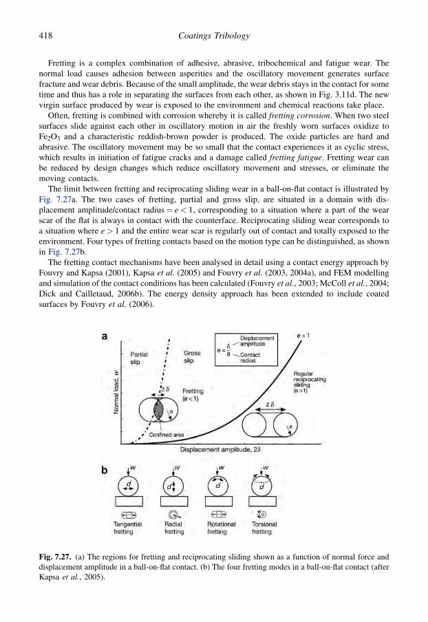
Fretting is a complex combination of adhesive, abrasive, tribochemical and fatigue wear. Thenormal load causes adhesion between asperities and the oscillatory movement generates surfacefracture and wear debris. Because of the small amplitude, the wear debris stays in the contact for sometime and thus has a role in separating the surfaces from each other, as shown in Fig. 3.11d. The newvirgin surface produced by wear is exposed to the environment and chemical reactions take place.
Often, fretting is combined with corrosion whereby it is called fretting corrosion. When two steelsurfaces slide against each other in oscillatory motion in air the freshly worn surfaces oxidize toFe2O3 and a characteristic reddish-brown powder is produced. The oxide particles are hard andabrasive. The oscillatory movement may be so small that the contact experiences it as cyclic stress,which results in initiation of fatigue cracks and a damage called fretting fatigue. Fretting wear canbe reduced by design changes which reduce oscillatory movement and stresses, or eliminate themoving contacts.
The limit between fretting and reciprocating sliding wear in a ball-on-flat contact is illustrated byFig. 7.27a. The two cases of fretting, partial and gross slip, are situated in a domain with dis-placement amplitude/contact radius¼ e< 1, corresponding to a situation where a part of the wearscar of the flat is always in contact with the counterface. Reciprocating sliding wear corresponds toa situation where e> 1 and the entire wear scar is regularly out of contact and totally exposed to theenvironment. Four types of fretting contacts based on the motion type can be distinguished, as shownin Fig. 7.27b.
The fretting contact mechanisms have been analysed in detail using a contact energy approach byFouvry and Kapsa (2001), Kapsa et al. (2005) and Fouvry et al. (2003, 2004a), and FEM modellingand simulation of the contact conditions has been calculated (Fouvry et al., 2003; McColl et al., 2004;Dick and Cailletaud, 2006b). The energy density approach has been extended to include coatedsurfaces by Fouvry et al. (2006).
Fig. 7.27. (a) The regions for fretting and reciprocating sliding shown as a function of normal force anddisplacement amplitude in a ball-on-flat contact. (b) The four fretting modes in a ball-on-flat contact (afterKapsa et al., 2005).
418 Coatings Tribology

7.8.2 Improvements by surface coatings
One way of controlling fretting is to apply surface coatings on one or both of the surfaces in contact.With a coating it is possible to reduce the friction and thus the surface stresses to change the me-chanical properties of the top layer resulting in changed stresses and surface toughness and to modifythe chemical interaction conditions between the surfaces and the environment. Coatings can bringbeneficial residual stresses to the top surface that inhibit crack propagation and wear debrisgeneration.
In a fretting contact with a coated surface the surface wear process often proceeds in two phases.First, there is mild wear of the top part of the coating but as the coating gets thinner the surface loadingis influencing the whole coating/substrate system and at some critical stage the coating is destroyedand delaminated. This process has been elegantly described by Liskiewicz and Fouvry (2005) anddemonstrated by a 12.7 mm radius alumina ball sliding against a 1.6 mm TiC coated high-speed steelsurface at 100 N normal load and �50 and �100 mm displacement gross slip amplitude with constant5 Hz frequency and 50% relative humidity. Based on experimental observations and theoreticalcontact and contact energy analysis they conclude that the lifetime is not only related to the pro-gressive wear mechanisms. It is also a function of more severe coating destruction mechanisms thatultimately drastically reduce the coating lifetime. They use a friction dissipation parameter, which isa unique parameter that takes into account the major loading variables, which are the pressure, slidingdistance and friction coefficient.
As wear of the coating top surface progresses and the coating becomes thinner, the cyclic stressesimposed through the coating/substrate interface are increased. After reaching a threshold stress value,i.e. below a critical residual coating thickness, a severe decohesion is activated resulting in coatingspalling and general surface failure. According to this hypothesis, damage evolves as progressive wearcontrolled by friction energy, followed by a quasi-instantaneous decohesion controlled by a criticaloverstressing of the coating/substrate interface, as shown in Fig. 7.28.
Liskiewitz and Fouvry (2005) further, very interestingly, calculate at different fretting cycles theratio between the experimental coating lifetime and the predicted endurance extracted from the weardepth modelling and receive a fairly constant value of 0.8. This indicates that the decohesion phe-nomenon seems to be activated, in the studied case, for a constant residual coating thickness of0.3 mm, which is related to a constant threshold of interface stress. The model enables the calculationof the endurance life of a coated surface in a fretting contact.
There are a few coating material fretting performance comparison studies published. Liskiewiczet al. (2005a) measured wear for a set of 1.6 to 4 mm thick hard PVD mainly titanium-based coated
Fig. 7.28. Illustration of a coating fretting wear scenario involving first a progressive energy controlledwear mechanism followed by a stress controlled instantaneous decohesion of the coating. he¼ effectiveworn coating thickness; hr¼ residual coating thickness at instant of spalling (after Liskiewitz and Fouvry,2005).
419Applications

high-speed steel surfaces sliding against an alumina ball at 15 to 150 N normal loads and with 50 to200 mm sliding amplitude. The best fretting wear resistance was measured for VC followed by Ti/VC,(TiC/VC)x2, TiC, TiCN and TiN, as shown in Fig. 7.29. Interestingly, the ranking does not correlatewith the coating hardness but it directly correlates with their Young’s modulus, the lowest modulusvalue giving best wear resistance.
The influence of friction in the fretting wear process is important. This is well illustrated by thestudy of Klafke (2004c) where he measured both the friction and the wear in fretting contacts withTiN, Ti(C,N), TiAlN and NiP coated high-speed steel surfaces, with and without a 2 mm thick DLC(a:C:H) top layer, in oscillating sliding against a 5 mm radius Al2O3 ball. The normal load was 10 N,the amplitude 200 mm and the frequency 20 Hz in non-lubricated conditions at 3, 50 and 100% relativehumidity. The results in Fig. 7.30 show the very clear reduction of friction with the DLC coatedsurfaces; the coefficient of friction is 2 to 35 times higher without the DLC coating. Similarly, there isa reduction in wear in most cases from 20% to more than one order of magnitude. The friction andfretting wear performance of the four coatings without a DLC top layer is very similar. A reduction infriction and wear with higher relative humidity is also clearly observed.
A very large variety of different coating materials, all from hard diamond, DLC and ceramiccoatings to soft and elastic PFTE and rubber coatings, have been studied and their tribological be-haviour reported. In most cases some beneficial effects in fretting resistance are reported. However,the tests are typically carried out with different contact and test parameters and comparisons to un-coated or some reference surfaces is in most cases, unfortunately, not reported. This makes it im-possible to rank the suitability of the coating materials for fretting resistance. Below is some of thereported coated surface fretting studies listed:
� Diamond coating (HF-CVD, h¼ 0.9 to 2.4 mm) on Ti–6Al–4V sliding against steel and alumina.Considerable reduction in friction and wear (Zeiler et al., 2000).� DLC coating (a-C:H, PA-CVD, h¼ 2–3 mm) on steel and on Ti-based coated steel surfaces sliding
against steel and alumina. Significant reduction in friction and wear compared to Ti-based coatedsurfaces. Friction coefficients of 0.01 to 0.1 and wear rates of 0.1 mm3/Nm have been reported.Friction and wear decreases with increasing humidity (Klafke, 2004c; Klafke et al., 2005a; Wascheand Klafke, 2008).� DLC coating lubricated (a-C:H, PVD/CVD, h¼ 2.7 mm) in oil coated on steel and sliding against
steel and DLC coated balls. DLC coatings reduced friction by more than a factor of 2 and wear by 3to 10 times compared to steel/steel contacts (Kalin and Vi�zintin, 2006).
Fig. 7.29. Coated surface durability under fretting wear for a given coating thickness in oscillating slidingagainst a 12.7 mm radius alumina ball with 100 N normal load, 100 mm sliding amplitude and 5 Hzfrequency (after Liskiewicz et al., 2004).
420 Coatings Tribology

Fig. 7.30. Coefficient of friction and wear after 100,000 oscillating sliding cycles for TiN, Ti(C,N), TiAlNand NiP coated high-speed steel surface, with and without a DLC (a:C:H) top layer sliding against a Al2O3
ball in (a) 3%, (b) 44–51% and (c) 100% relative humidity. The wear is given as the section area betweenthe worn wear groove and the unworn surface (data from Klafke, 2004c).
421Applications

� TiN coating (PVD, h¼ 1 to 4 mm) on steel surfaces sliding against alumina. Decrease in friction andwear with increasing humidity (Cosemans, 2003; Zhang et al., 2003a; Klafke, 2004c; Liskiewiczet al., 2004; Caron et al., 2006).� TiAlN, TiCN, TiC, VC, TiC/VC, NiP, a-TiB2 coatings (PVD, h¼ 1 to 4 mm) on steel sliding against
alumina (Zhang et al., 2003a; Klafke, 2004c; Liskiewicz and Fouvry, 2005; Liskiewicz et al., 2004,2005).� TiN–MoSx coating (PVD, h¼ 3.3 to 4 mm) on steel surface sliding against steel and alumina. Five
hundred times lower wear compared to TiN (Cosemans et al., 2003).� Multilayer TiAlCN/TiAlN/TiAl and TiC/VC coatings (PVD, h¼ 1.6 and 4 mm) on steel sliding
against alumina. Wear reduced with a factor of 3 compared to uncoated surface for the firstmentioned multilayer (Fouvry et al., 2004b; Larbi and Tlili, 2006).� Si3N4 and SiO2 coatings (PECVD, h¼ 0.1 to 1 mm) on silica and glass sliding against alumina
(Klafke and Beck, 2000) and Si3N4 coating (PECVD, h¼ 0.3 mm) on titanium alloys sliding againsttitanium alloy balls (Yanito et al., 2006).� Cu–Ni–In coating (plasma spraying, h¼ 150 to 200 mm) on Ti–6Al–4V surface sliding against Ti–
6Al–4V (Fridrici et al., 2003).� MoSx coating (PVD, h¼ 0.1 to 1 mm) on steel sliding against alumina (Zhang et al., 2003a).� PTFE coatings (h¼ 6 to 30 mm) on steel surface sliding against steel. No correlation between
coating thickness and endurance life but friction normally decreases with increasing thickness(Langlade et al., 2005).� Rubber fluoropolymer coating (screen-printing, h¼ 500 mm) on steel sliding against steel. Co-
efficient of friction decreases with increasing load and increases with increasing velocity (Baek andKhonsari, 2005).
7.9 Magnetic Recording Devices
7.9.1 Description of the application
The magnetic recording devices used in computers and other electronic instruments for audio, videoand data-processing are tape drives, floppy disk (diskette) drives and rigid disk drives, as shown inFig. 7.31. The magnetic read–write process takes place simultaneously with relative motion betweenthe magnetic media and a stationary or rotating magnetic head. Under steady operating conditions, themagnetic head flies over the surface of the magnetic media supported by a hydrodynamic air film. Atthe moments of starting and stopping there is direct contact between the head and the media.
In rigid disk drives and computer tape drives the thickness of the air film is in the range of 10 to50 nm and the RMS roughness of the head and magnetic medium surfaces ranges from 1 to 10 nm.The areal data densities of commercial tape and rigid disk drives are in the range of 10 to 100 Gbit/in2.The higher value corresponds to track densities of 6000 to 8000 tracks/mm. Thus the size of a bitdimension for these densities is of the order of 160 nm� 40 nm. This small dimension forms a hardrequirement on the defect size limit in the head and medium surfaces. The goal of the immediatefuture is a storage capacity of 1 Tbit/in2, which would require flying heights to be reduced to 1 to 3 nm(Bhushan, 1988, 1990, 1996, 2001a, b; Talke, 1991, 2000; Menon, 2000; Carnes, 2004; Gellman andSpenser, 2005).
The need for higher recording densities requires that the flying heights are as low as possible andthe surfaces are as smooth as possible. Closer flying heights result in occasional rubbing of highasperities and increased wear. Smoother surfaces will increase the friction and the interface tem-peratures. High interface reliability through the whole life of the magnetic storage is most important,since interface failure, even on a microscopic scale, can result in loss of valuable data recorded on themagnetic media.
422 Coatings Tribology
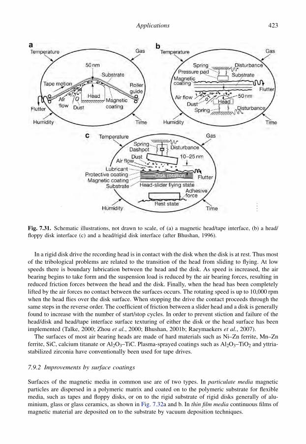
In a rigid disk drive the recording head is in contact with the disk when the disk is at rest. Thus mostof the tribological problems are related to the transition of the head from sliding to flying. At lowspeeds there is boundary lubrication between the head and the disk. As speed is increased, the airbearing begins to take form and the suspension load is reduced by the air bearing forces, resulting inreduced friction forces between the head and the disk. Finally, when the head has been completelylifted by the air forces no contact between the surfaces occurs. The rotating speed is up to 10,000 rpmwhen the head flies over the disk surface. When stopping the drive the contact proceeds through thesame steps in the reverse order. The coefficient of friction between a slider head and a disk is generallyfound to increase with the number of start/stop cycles. In order to prevent stiction and failure of thehead/disk and head/tape interface surface texturing of either the disk or the head surface has beenimplemented (Talke, 2000; Zhou et al., 2000; Bhushan, 2001b; Raeymaekers et al., 2007).
The surfaces of most air bearing heads are made of hard materials such as Ni–Zn ferrite, Mn–Znferrite, SiC, calcium titanate or Al2O3–TiC. Plasma-sprayed coatings such as Al2O3–TiO2 and yttria-stabilized zirconia have conventionally been used for tape drives.
7.9.2 Improvements by surface coatings
Surfaces of the magnetic media in common use are of two types. In particulate media magneticparticles are dispersed in a polymeric matrix and coated on to the polymeric substrate for flexiblemedia, such as tapes and floppy disks, or on to the rigid substrate of rigid disks generally of alu-minium, glass or glass ceramics, as shown in Fig. 7.32a and b. In thin film media continuous films ofmagnetic material are deposited on to the substrate by vacuum deposition techniques.
Fig. 7.31. Schematic illustrations, not drawn to scale, of (a) a magnetic head/tape interface, (b) a head/floppy disk interface (c) and a head/rigid disk interface (after Bhushan, 1996).
423Applications

In addition to the magnetic particles, hard ceramic particles of Al2O3 are generally added into thepolymeric matrix, as shown in Fig. 7.33. The thickness of the magnetic disk coating may be less than1 mm. Needle-like g-Fe2O3 particles, about 1 mm long and 0.05 mm in diameter are longitudinallyoriented in the magnetic coating. The embedded hard Al2O3 or Cr2O3 particles have a diameter ofabout 0.2 to 0.3 mm (Bhushan, 2001b).
The hard particles will inhibit strong sticking of the very smooth head and disk surfaces in contactsituations and protect against wear. The concentration of particles necessary to provide good tri-bological properties is, however, critical. As the Al2O3 content increases the wear mechanism willchange from adhesive wear to more abrasive wear. The optimum content of particles to provide goodendurance of the contact has been estimated to be about 8% (Kita, 1991). The influence of the alu-minium oxide particle content in the layer on disk wear, counterface wear and friction is shown inFig. 7.34. The drastic drop of the coefficient of friction in the low particle content region of Fig. 7.34cis believed to be due to decreased adhesion between the surfaces.
A typical coating binder layer for a recording tape is 2 to 5 mm polyester–polyurethane on a 23 mmthick polyethylene terephthalate (PET) tape substrate (Bhushan, 1988, 1990, 2001b). A sectional viewof a particulate magnetic tape is shown in Fig. 7.32a. The magnetic particles are acicular particlessuch as g-Fe2O3, CrO2, Fe or hexagonal platelets of barium ferrite.
In a large screening study performed with an accelerated wear test apparatus, Bhushan (1987)compared the wear resistance and friction of 24 different head material candidates from stainless steeland tool steel to ceramics, cermets and glass as well as coatings deposited by plasma spraying,sputtering and anodizing sliding against magnetic tape. Coating materials were Al2O3, Al2O3–TiC,
Fig. 7.32. Sectional views of (a) a particulate magnetic tape, (b) a particulate rigid disk and (c) a thin filmrigid disk (data from Bhushan, 1996, 2001a; Gellman and Spenser, 2005).
424 Coatings Tribology

Al2O3–TiO2, WC–Co, TiC, Cr2O3, TiN, Triballoy 800 and hard-coat anodized aluminium. The lowestwear was found for solid ceramics and cermets.
Floppy disks have a similar construction and composition to tapes, except that the substrate isthicker and it has a magnetic coating on both sides. A typical coating binder layer is 2 to 5 mmpolyester–polyurethane and epoxy on the 75 mm PET floppy disk substrate (Bhushan, 1988, 1990,
Fig. 7.33. Sectional view of a particulate magnetic disk with needle-like magnetic particles and hardaluminium oxide particles (after Kita, 1991).
Fig. 7.34. Disk wear volume, pin counterface wear rate and coefficient of friction as functions of the alu-minium oxide content in the magnetic layer of rigid disks. Data from experiments with a load of 60 mN,a sliding distance of 5.4 km and a speed of 3 m/s in (a) and (b), and 0.05 m/s in (c) (data from Kita, 1991).
425Applications

2001b). While the floppy disks operate only in occasional physical contact with the head, load-bearingAl2O3 or Cr2O3 particles are sometimes added to increase the wear resistance.
The hard disk in a magnetic recording disk drive is made of aluminium or glass which is coated bysputtering with a thin metallic magnetic layer. The magnetic layer is protected by a thin carboncoating, which is protected by a very thin layer of liquid lubricant, typically perfluoropolyalkyl ethers(PFPEs), as shown in Fig. 7.32c.
Today, sputtered hydrogenated diamond-like carbon (DLC) is almost exclusively used as theprotective overcoat material for rigid disks. There are two types in use: amorphous hydrogenatedcarbon (a-C:Hx) and amorphous nitrogenated carbon (a-CNx). These overcoats are quite complexmaterials and the details of their structure at the atomic level are not completely known. As they areexposed to air immediately after deposition their surfaces are partially oxidized (Gellman andSpenser, 2005).
In high-speed tests using a pin-on-disk apparatus Li et al. (1991) showed that glass-based thin filmdisks are more wear resistant than aluminium-based ones, and thin film disks are considerably morewear resistant than aluminium oxide ones. On the top of the glass substrate there was a sputteredchromium film with a thickness of 200 nm, which was used to enhance the magnetic properties of themedium. The magnetic medium was made of a cobalt-based alloy, which was sputtered over thechromium film and had a thickness of about 80 nm. A carbon overcoat was finally sputtered on top ofthe magnetic medium with a thickness in the range of 40 to 45 nm. Advantages of using glass asa substrate are its hardness and the fact that it can easily be polished to extreme smoothness.
A variety of different DLC coatings have been investigated for use on magnetic disks (Tsui et al.,1995; Bhushan, 2001b; Schlatter, 2002). Several attempts have been made to try to correlate thecoating structure to the tribological properties. Since the tribological properties of DLC coated rigiddisks are affected by various factors the friction and wear characteristics can vary significantly duringsliding.
The friction and wear mechanisms involved in the sliding contact of a commercially available thinfilm rigid disk with sputtered DLC overcoat sliding against an Al2O3–TiC magnetic recording headwere studied by Wei and Komvopoulos (1997). They found that the friction behaviour of the head/diskinterface is mainly due to the wear process occurring on the carbon film surface. The initial frictionforce was mainly due to asperity deformation and ploughing, while adhesional friction was secondary.At this stage the wear was mainly due to asperity nanofracture generating ultra-fine wear debris whichcaused an increase in the coefficient of friction. The steady-state friction was observed to be due to theconcurrent effects of different wear processes on the DLC coated surface. The graphitization ofamorphous carbon wear debris changes the interfacial energy and shear strength, thereby affecting thesteady-state tribological behaviour. The topographies of unworn and worn carbon coatings havedifferences only in submicrometre-sized surface features, indicating that knowledge on nanoscalewear processes is of primary importance in magnetic recording.
Another approach has been to deposit a DLC coating on the sliding head. Kohira et al. (2000) in-vestigated different slider designs with surfaces sputter deposited with a 1.5 nm silicon underlayer anda 5.5 nm thick DLC overcoat. The wear of the DLC coated sliders was proportional to the calculatedcontact force and the wear did level off after 10 km of sliding distance regardless of slider design.
Surface texturing has been investigated to reduce the stiction force caused by the contact ofextremely smooth surface head sliders and rigid disks. Zhou et al. (2000) compared four kinds of hardcoating materials on textured slider surfaces with a drag test. They found that the a-CNx coating hada higher wear resistance than sputtered carbon, TiNx and BN coatings.
The DLC overcoat is normally covered by a disk lubricant layer, most commonly perfluoropolyalkyl ethers (PFPE). The main function of the lubricant is to reduce the wear of the disk surface andto ensure that the friction remains low throughout the lifetime of the device. The lubricant should havethe ability to adhere to the disk, have a good load-carrying capacity and be mobile in order to repaircontact displacements. It should not evaporate from the disk during the lifetime of the disk, which is 5 to
426 Coatings Tribology
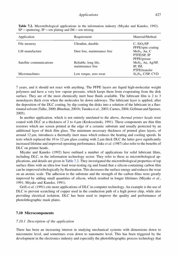
7 years, and it should not react with anything. The PFPE layers are liquid high-molecular weightpolymers and have a very low vapour pressure, which keeps them from evaporating from the disksurface. They are of the most chemically inert base fluids available. The lubricant film is 2 to 3monolayers thick even when the molecules lie down sideways. The lubricant layer is applied, afterthe deposition of the DLC coating, by dip coating the disks into a solution of the lubricant in a fluo-rinated solvent (Talke, 2000; Bhushan, 2001b; Tanaka et al., 2003; Carnes, 2004; Gellman and Spenser,2005).
In another application, which is not entirely unrelated to the above, thermal printer heads werecoated with DLC at a thickness of 2 to 4 mm (Krokoszinski, 1991). These components are thin filmresistors which are screen printed at the edge of a ceramic substrate and usually protected by anadditional layer of thick film glass. The minimum necessary thickness of printed glass layers, ofaround 12 mm, introduces a thermally inert mass which reduces the heating and cooling speeds. Intests which replaced the 10 to 12 mm glass coating with 2 mm thick DLC the latter gave significantlyincreased lifetime and improved operating performance. Enke et al. (1987) also refer to the benefits ofDLC on printer heads.
Miyake and Kaneko (1992) have outlined a number of applications for solid lubricant films,including DLC, in the information technology sector. They refer to these as microtribological ap-plications, and details are given in Table 7.2. They investigated the microtribological properties of topsurface films with an ultra-low load wear-testing rig and found that a silicon-containing carbon filmcan be improved tribologically by fluorination. This decreases the surface energy and reduces the wearon an atomic scale. The adhesion to the substrate and the strength of the carbon films were greatlyimproved by adding small quantities of silicon, which resulted in longer lifetimes (Miyake et al.,1991; Miyake and Kaneko, 1991).
Grill et al. (1991) cite more applications of DLC in computer technology. An example is the use ofDLC to prevent scratching of copper used in the conduction path of a high power chip, while alsoproviding electrical isolation. DLC has been used to improve the quality and performance ofphotolithographic mask plates.
7.10 Microcomponents
7.10.1 Description of the application
There has been an increasing interest in studying mechanical systems with dimensions down tomicrometre level, and sometimes even down to nanometre level. This has been triggered by thedevelopment in the electronics industry and especially the photolithographic process technology that
Table 7.2. Microtribological applications in the information industry (Miyake and Kaneko, 1992).SP¼ sputtering, IP¼ ion plating and IM¼ ion mixing.
Application Requirement Material/Method
File memory Ultrathin, durable C, SiO2/SPPFPE/spin coating
LSI manufacture Dust free, maintenance free MoS2, Au, CPTFE/SP, IPPFPE/grease
Satellite communications Reliable, long life,maintenance free
MoS2, Au, Ag/SP,IP, IM,PTFE/transfer
Micromachines Low torque, zero wear Si3N4, C/SP, CVD
427Applications

made it possible to produce microcomponents and microdevices, known as microelectromechanicalsystems (MEMS). Today the lithographic processes have been complemented by a number ofmicromanufacturing methods like microcutting, microdrilling, micromilling, microsparc erosion,focused ion beam, laser ablation, laser machining and laser polymerization.
A variety of miniaturized components and devices have been fabricated for demonstration pur-poses: acceleration, pressure and chemical sensors, linear and rotary actuators, electric motors, gears,transmissions, gas turbines, pumps, valves, nozzles, cranks, sliders, springs, switches, grippers,pin joints, ratchets, tweezers, optoelectronic devices and magnetic recording (Muller, 1990;Komvopoulos, 1996; Bhushan, 1998b, 1999b, 2001c, d; Sundararajan and Bhushan, 2001a, b). Thedimensions of the devices are in the range of one micrometer to some millimetres. One of thefirst large-scale commercial products was the acceleration MEMS sensor in cars for triggeringthe safety air-bags in collisions. Another is digital micromirror positioning device in laser printersand digital high-resolution projection devices. The fabrication of MEMS is described elsewhere(e.g. Komvopoulos, 1996; Sundarajan and Bhushan, 2001b).
The first used lithographic process was limited to silicon materials, which today are still dominatingthe MEMS applications due to the available machining technology. More recent micromachiningprocesses extend the material choice to metals, ceramics and polymers. However, there are severaldesign problems to overcome in downscaling a mechanical device from, e.g., 1 millimetre to1 micrometre. The length decreases with three orders of magnitude, the related area with six orders ofmagnitude and the related volumes with nine orders of magnitude. Thus the forces that are pro-portional to the area, such as friction, adhesion, viscous drag and surface tension, will increase 1000times in comparison with the forces related to volume, such as inertial and electromagnetic forces.This gives a more critical role to friction and wear in the functionality of the microdevices, seeFig. 7.35. In lubrication the continuum theory breaks down in the analyses of, e.g., fluid flow inmicrodevices. Another challenge is the material choice. The bulk silicon and polysilicon films fre-quently used in microdevices normally have high friction and wear in sliding applications. Their staticcoefficient of friction may vary in the range of 0.2 to 4.9 (Suzuki et al., 1991; Deng and Ko, 1992;Komvopoulos, 1996; Krauss et al., 2001; Sundararajan and Bhushan, 2001b; Rha et al., 2005).
7.10.2 Improvements by surface coatings
Silicon-based MEMS devices are made from single crystal silicon, polycrystalline silicon (poly-silicon) films deposited by low-pressure CVD and certain ceramic films on silicon. For high-temperature applications SiC films are used. Bhushan (2001d) studied the tribological performance ofseven bulk and treated silicon samples, and polysilicon coated and SiC coated silicon wafers with3 mm film thickness by surface characterization and tribological testing on both the macro- andmicroscale. The coefficient of friction was in general about one order of magnitude higher inmacroscale reciprocating ball-on-flat testing with a 1.5 mm radius sapphire ball compared tomicroscale testing with a modified AFM/FFM with a 50 nm radius Si3N4 ball.
The macroscale coefficient of friction for the tested surfaces was in the range of 0.2 to 0.46 while ona microscale it was in the range of 0.02 to 0.07, as shown in Fig. 7.36. The microscale friction is lowerbecause there is less ploughing friction contribution in the microscale measurements. Doping of thepolysilicon coating did not significantly affect its tribological properties that were very similar tothose of undoped single-crystal silicon. The SiC coated surfaces were superior with regards to theirfriction and wear performance. This is believed to be due to their higher hardness and fracturetoughness. Polishing the surface reduced the coefficient of friction by 20 to 70% in microscale frictiontests, as shown in Fig. 7.37.
There have been attempts to use diamond or DLC coatings to reduce friction and improve wearresistance in MEMS devices. Difficulties with using diamond coatings are related to fabricatingsurfaces with a morphology suitable for MEMS. Diamond coatings produced by conventional CVD
428 Coatings Tribology
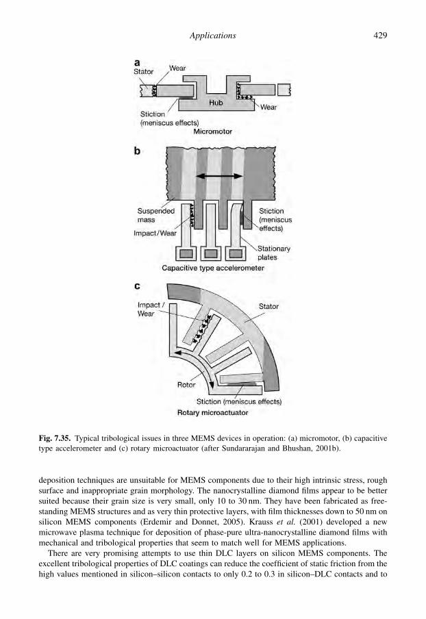
deposition techniques are unsuitable for MEMS components due to their high intrinsic stress, roughsurface and inappropriate grain morphology. The nanocrystalline diamond films appear to be bettersuited because their grain size is very small, only 10 to 30 nm. They have been fabricated as free-standing MEMS structures and as very thin protective layers, with film thicknesses down to 50 nm onsilicon MEMS components (Erdemir and Donnet, 2005). Krauss et al. (2001) developed a newmicrowave plasma technique for deposition of phase-pure ultra-nanocrystalline diamond films withmechanical and tribological properties that seem to match well for MEMS applications.
There are very promising attempts to use thin DLC layers on silicon MEMS components. Theexcellent tribological properties of DLC coatings can reduce the coefficient of static friction from thehigh values mentioned in silicon–silicon contacts to only 0.2 to 0.3 in silicon–DLC contacts and to
Fig. 7.35. Typical tribological issues in three MEMS devices in operation: (a) micromotor, (b) capacitivetype accelerometer and (c) rotary microactuator (after Sundararajan and Bhushan, 2001b).
429Applications

0.04 to 0.06 in DLC–DLC contacts when both surfaces are coated (Suzuki et al., 1991; Deng and Ko,1992; Komvopoulos, 1996; Rha et al., 2005; Smallwood et al., 2006). High intrinsic stresses in ta-CDLC films may restrict their use.
The tribological properties of a coated or uncoated MEMS surface can be further improved bya suitable lubricant film. Again, the scaling down to microlevel brings new features into lubricationtechnology and the rules we used to apply on the macrolevel do not always apply. The continuum
Fig. 7.36. Comparison of tribological scale effects: (a) macroscale coefficient of friction in reciprocatingtribotester, (b) microscale coefficient of friction measured by AFM/FFM and (c) microscale wear mea-sured by AFM (data from Bhushan, 2001d).
Fig. 7.37. Comparison of (a) rms surface roughness and (b) coefficients of microscale friction for varioussamples (data from Bhushan, 2001d).
430 Coatings Tribology

theory on which the classical approach to lubrication is based, with freely supported multimolecularlayers of liquid lubricants, does not apply when approaching monolayer lubricant films. In traditionallubrication these can physically or chemically adsorb onto polar surfaces by their functional groups toform close-packed arrangements of lubricant chains oriented almost perpendicular to the substratesurface. The use of fluid lubricants on the microscale may introduce capillary and viscous shearmechanisms which result in energy dissipation. Consequently, the ideal lubricants for MEMS devicesare ultra-thin layers covalently bonded to micromachined surfaces.
Grafting of densely packed organic molecules to obtain nanometre thick monolayers is especiallyadvantageous because the typical surface separation distances are in the range of 0.5 to 2 mm. Themonolayers must exhibit high hydrophobicity and low surface energies to minimize capillary forces,low frictional shear to yield minimal energy losses and high wear resistance and stability over longtime periods. Such lubricant layers are typically long-chain hydrocarbon and fluorocarbon moleculesand they are referred to as self-assembled monolayers (SAM). The PFPE lubricant films successfullyused in magnetic hard disk drives may also be suitable for MEMS applications (Komvopoulos, 1996;Bhushan, 2001d; Sundararajan and Bhushan, 2001b; Hsu, 2004a, b).
7.11 Biomedical Applications
7.11.1 Description of the application
In the biological world, nature has created a huge number of fascinating and efficient tribologicalsolutions. Tribology is related to mobility in humans and animals. High friction is required foracceleration, deceleration and manoeuvring while low friction is needed in joints for economic energyexpenditure and low wear. A healthy human joint has a remarkable lifetime of typically 75 years withmore than 1 million loading cycles per year (Fisher, 2001; Scherge and Grob, 2001; Dowson andNeville, 2006).
Biomedical tribological systems involve a large range of synthetic materials and natural tissues,which often operate in complex interaction with the biological environment. Their performance re-quirements are complex and the lifetime requirement often considerably exceeds that of engineeringsystems.
The field of medical implants in the human body is a growing area with several tribological aspects.This application sector has its own specific characteristics, dominated by stringent quality re-quirements, due to the human suffering and sometimes life-threatening consequences of a surfacefailing to fulfil its required function. Rejection of body implants is caused by poor biocompatibility ofthe surface of the implanted material. Surgical tools, which must be sharp, can corrode rapidly inphysiological fluids. Other problems include fretting and wear in orthopaedics and dentistry, such asbrackets, pins and plates for bridges, and haemocompatibility of cardiovascular applications such asavoidance of blood clots.
Total hip joint replacements, shown in Fig. 7.38b, are the largest field of tribological implants. Hipreplacements are used in the case of either osteoarthritis or hip fracture. In the 1980s there were 120,000total hip joint replacement surgeries per year and in 2006 the number had increased to about onemillion. Osteoarthritis of the hip joint is manifested by the degradation of the cartilage layer, leading toa breakdown of the low-friction contact between the femoral head and the acetabulum in the pelvis. Inthe absence of a viable drug therapy, complete or partial replacement of the degenerated joints is themain available treatment. The lifetime of hip joint replacements is about 10 to 15 years, and some 12%of patients require second replacements. There is currently an urgent need to extend the treatment topatients under 50 years who would require replacements to last at least 20 to 50 years. There are threemain factors which limit this: (a) insufficient wear resistance, (b) loosening of the stem to hip caused bywear particles or (c) cement-to-bone interface failure or implant-to-bone interface failure.
431Applications

Current total hip joint implant material combinations are mainly:
� metal head against polymer cup, e.g. CoCrMo/UHMWPE, stainless steel/UHMWPE,� ceramic head against polymer cup, e.g. alumina/UHMWPE , zirconia/UHMWPE,� metal head against metal cup, e.g. CoCrMo/CoCrMo, and� ceramic head against ceramic cup, e.g. alumina/alumina.
The metal/UHMWPE material combination has dominated the market in the last decade. Recentinvestigations shows that both metal–metal and ceramic–ceramic joint implants reduce the wearconsiderably and are very promising future long lifetime solutions (Rieker, 1998; Ajayi et al., 2005;Dowson and Jin, 2006; Unsworth, 2006). However, there are concerns about the toxicity of metal wearparticles and elevated metal ion levels in the human body (Fisher et al., 2004). Total knee implants arepredominately metal against polymer.
The lubrication mechanism in a natural hip joint is a complex combination of weeping, elasto-hydrodynamic fluid film, boosted, boundary and biphasic lubrication. The lubrication mechanismbetween the synthetic surfaces of hip implants is simpler and the lubrication conditions can beclassified as boundary and mixed lubrication with occasional full surface separation. The lambdavalue (film thickness–surface roughness) is for metal–polymer joints typically <1 and for metal–metal joints typically<3. During a walking cycle a load of 4 to 5 times the body weight is transmittedand a typical load variation is 0.3 to 3 kN, the sliding velocity is up to 50 mm/s and the film thicknessin a total hip joint implant is about 0.05 to 0.25 mm (Fisher, 2001; Unsworth, 2006; Dowson andJin, 2006).
The coefficient of friction in a hip joint implant is typically in the range of 0.02 to 0.15, while ina healthy human joint it is as low as 0.002 to 0.025, which, indeed, is remarkably low at such lowspeeds. It appears, however, that the major tribological problem is not the change in surfaces due towear but the large amount of wear debris produced in the contact and that plays a significant role inpromoting loosening of both femoral stems and acetabular cups. Wear particles in the size range of 0.1to 7 mm cause a macrophage biological reaction that causes bone resorption (Dowson, 1989;Davidson, 1992; Saikko, 1993; Hills, 2000; Fisher, 2001; Unsworth, 2006; Ahlroos, 2001; Calonius,2002; Santavirta, 2003; Ajayi et al., 2005; Briscoe and Sinha, 2005; Hutchings, 2007).
Fig. 7.38. Schematic illustration of (a) a natural joint in the lower limb and (b) a total replacement hipjoint.
432 Coatings Tribology
7.11.2 Improvements by surface coatings
Coatings are increasingly being used as enhancement, rather than protective, layers, e.g. on ortho-paedic implants to facilitate bonding direct to the bone. One example of coatings to enhance prop-erties are the bioactive calcium phosphate (hydroxyapatite) coatings. These accelerate bone fixationand reduce metal ion release (Habibovic et al., 2002).
A potentially very promising coating in the medical sector is diamond-like carbon. Studies on itsbiocompatibility have shown that DLC is an inert, impervious hydrocarbon with properties suitablefor use in the biomedical field, particularly in orthopaedic implants.
DLC adheres strongly to a range of materials used in bio-engineering including metals such astitanium and cobalt chromium, and various plastics including polyethylene and polyurethane. It canprovide a chemically protective, wear-resistant and low-friction coating on such materials in a bi-ological environment. Laboratory studies with mouse macrophage cells and fibroblast cells showedenzyme levels indicating no inflammatory response or loss of cell integrity from contact with DLC.Morphological examination confirmed the biochemical results that no cellular damage had occurred(Aisenberg, 1977; Franks et al., 1990; Evans et al., 1991; Thomson et al., 1991; Cui and Li, 2000;Chu et al., 2002; Reuter et al., 2006).
In a reciprocating pin-on-disk tribotest study Ajayi et al. (2005) compared the tribological prop-erties of typical in-use hip joint material combinations, stainless steel, alumina, zirconia andUHMWPE balls with a PACVD 2 mm thick DLC coating on steel ball, all sliding in commercialbovine blood serum against a polished stainless steel flat surface. The DLC coated surface had almostas low a coefficient of friction, 0.055, as the conventionally used UHMWPE surface, 0.03, while theother material combinations had considerably higher coefficients of friction, in the range of 0.09 to0.115, as shown in Fig. 7.39. The DLC coated surface had the lowest wear, almost four orders ofmagnitude lower than the UHMWPE and several times lower than the other tested ball materials.Furthermore there was no wear of the uncoated steel surface.
There is some contradiction in the reported results of the tribological properties of DLC coatingsused in synovial hip joints and that may be due to the quality of the deposited coatings and thecountersurface material used. The 3 mm thick DLC coatings deposited by a hybrid PVD/CVD processon CoCr heads did not differ markedly in wear behaviour when sliding against UHMWPE in a hipjoint simulator compared to alumina and uncoated CoCr heads (Saikko et al., 2001).
On the other hand, remarkably low wear, low friction in the range of m¼ 0.03 to 0.06 and a neg-ligible amount of wear debris was recorded when Santavirta et al. (1999) and Lappalainen et al.(2003) carried out both pin-on-disk and hip joint simulator tests with high-quality DLC coated metalheads. The DLC coatings were deposited by a filtered pulsed arc discharge method resulting in verysmooth and pure DLC (ta-C) coatings. The hydrogen content was less than 0.1 at.% and the overallpurity was greater than 99 at.%. It is interesting that they report tests with thin DLC coatings in therange of a few mm but also tests with comparably thick DLC coatings, in the range of 40 to 100 mm.They report wear rates of 0.0001 to 0.001 $ 10�6 mm3/Nm for DLC/DLC pairs, 0.001 to 0.1 foralumina/alumina pairs, 1 to 30 for CoCrMo/CoCrMo pairs and 5 to 100 for UHMWPE/CoCrMo pairs,as shown in Fig. 7.40.
Promising results of the use of DLC coatings in hip joint implants have further been reported byField et al. (2004) and reviewed by Hauert et al. (2004). In the investigation by Fisher et al. (2004)they compared in a hip joint simulator the wear properties of a conventional CoCrMo/CoCrMo hipjoint to three 8 to 12 mm thick coatings, arc evaporation PVD TiN, CrN and CrCN, and one thin 2 mmPACVD DLC coating deposited on CoCrMo. They report that thin 1 to 2 mm TiN and DLC coatingscan wear through while the most promising results were achieved for thicker 8 to 12 mm CrN andCrCN coated surfaces. The TiN coated surface may be improved by chlorine ion implantation of thesurface (Gispert et al., 2007). In a reciprocating ball-on-flat screening test with distilled water the
433Applications

tested DLC coatings outperformed, in terms of friction and wear behaviour, standard TiN, TiC,Ti(C,N), CN, CrN coatings as well as more complicated Ti-based multilayer systems (Osterle et al.,2007). The test conditions were a reciprocating 10 mm diameter alumina ball sliding against thecoatings with 2 mm stroke length, 2 Hz frequency and 10 N normal load resulting in a mean Hertzianpressure of 600 MPa.
The deposition of PVD diamond-like carbon coatings on prosthetic artificial heart valves of NiCr18stainless steel or TC4 alloy seems to be a potentially useful application. Zheng et al. (1991) haveshown that they satisfy both the mechanical and biological requirements of artificial heart valves.
The use of DLC coatings to improve surgical needles used in corneal surgery, such as cornealtransplant and cataract operations, has been investigated by Grant et al. (1992). They carried out twotypes of test. One involved inserting 0.8 mm diameter AISI 430 stainless steel needles in pigs’ eyes todetermine the frictional resistance to penetration. The second involved a ball against flat fretting testwith a 5 mm diameter ball, a 14 N normal force, a 110 mm amplitude at 10 Hz and the same materials.The penetration tests showed that a DLC coating would typically reduce the necessary penetrationforce by 30%. The fretting test showed, on the one hand, that deposition process optimization was stillrequired but, on the other hand, that the driving force would be significantly reduced using the DLCcoating and that excellent wear resistance can be achieved.
PVD titanium nitride coatings have been shown to offer 300 times reduction in anodic dissolutionin physiological solutions compared to the uncoated stainless steel normally used for surgical knives(Gordashnik et al., 1983).
Fig. 7.39. (a) Average coefficient of friction and (b) wear volume of various in-use and potential hip jointball materials sliding on a stainless steel flat surface in a reciprocating pin-on-disk test (after Ajayi et al.,2005).
434 Coatings Tribology

Dental prostheses are required to possess very high strength and hardness, but also extremely goodbiocompatibility with the adjacent human tissue and teeth. Two competing material types are in use.Titanium materials are extremely compatible but their low strength means that the dentures have to berelatively thick. Chromium–cobalt alloys combine high hardness and strength with the greatest degreeof denture-making know-how. Knotek et al. (1992e) have shown that it is possible to combine thegood properties of these materials by developing a cobalt–chromium–molybdenum alloy witha multilayer PVD titanium nitride coating. Laboratory corrosion tests showed that a two-layer tita-nium nitride coating had excellent corrosion resistance. The special advantage of a two-layer structureis that intermediate etching reduces the number of defects remaining in the coating and henceincreases its impermeability to corrosive attack, as shown in Fig. 7.41.
7.12 Future Issues
The applications described within this chapter, and those mentioned elsewhere in the book, show thatthin coatings deposited by various, mainly PVD- and CVD-based, techniques have been a majorsuccess when applied on components and tools in many industrial sectors. The improvements havebeen a considerable reduction in friction, decreased wear and increased component lifetime, some-times by even several orders of magnitude, resulting in improved production efficiency, productivity,reliability and cost efficiency. A summary of ten representative areas of applications for thin hardcoatings including typical coating materials, thicknesses, substrates, counterfaces and achieved tri-bological improvements based on the examples referred to in this chapter are presented in Table 7.3.
The requirements from coatings have changed over the years, depending on the types of substratesin prevalent use and the demands of some key application sectors, such as automotive and aerospace.Two decades ago there was a perceived need to widen the applicability of advanced tribologicalcoatings to low-cost substrate materials, for example by developing low-temperature coating pro-cesses and also devising duplex and hybrid processes which could ensure that those substrates could
Fig. 7.40. Experimental wear rates of some material combinations used in knee and hip joint implants.Some of the values are based on data reported in the literature and other values are estimates using datafrom clinical surveys or hip joint simulator studies (data from Santavirta et al., 1999).
435Applications

provide the load support needed for PVD coatings. These objectives have been achieved to someextent.
However, what has also happened is that there has been a refinement in the way that the PVDcoatings themselves have evolved, to match the requirements of the substrates and the applications.We now see many tailored coatings designed for specific needs. There is an increasing emphasis onfrictional performance, which is not surprising, given the current interest in energy efficiency andresource conservation. We have seen in the book how frictional control and adaptability to operatingrequirements can be achieved through process and materials innovations such as nanocomposite,amorphous and glassy metal coatings.
We can expect these developments to continue – especially in the areas of adaptive and gradientcoatings designed specifically for a given set of contact conditions. Given the excellent tribologicalperformance largely confirmed in a wide range of operating conditions of coatings based on DLC andMoS2, we can expect those materials in various forms and combinations to be used increasingly, oftenin conjunction with other materials.
The optimization of mechanical properties will be aided by the use of multiscale modellingtechniques such as FEM, and other computer-based methods, including molecular dynamic simula-tion, which will provide a better understanding of atomic and molecular level tribomechanics andscaling effects.
We envisage that recent interesting findings relating to the influence of surface texture will lead toa widening of the use of surface topography control and enhancement methods including, for ex-ample, laser texturing.
A further important benefit will be the development of lubricant additives tailored to work togetherwith specific coatings to achieve optimized surface interactions for improved tribological perfor-mance. This will be one example where controlled tribochemistry will enhance performance. Anotherwill be the study and optimization of transfer layer development and third-body generation. We alsoanticipate improved control of coated surface fracture behaviour by the adoption of fracture me-chanics analyses for hard coatings
We can see the need in all safety-critical parts to have means to monitor the condition of tribo-surfaces. We can therefore expect to see intelligent coatings developed, which provide information on
Fig. 7.41. (a) Pitting corrosion in chloride-containing electrolytes, (b) coating failure at a single layer and(c) the multilayer principle of coating density improvement (after Knotek et al., 1992e).
436 Coatings Tribology

Table 7.3. Typical coating applications and level of improvements.
Application Coating Thickness, mm Substrate Countersurface Improvements
1. Slidingbearings
DLC, PTFE, MoS2,graphite
5–50 Steel Steel Up to 7 times reduced wearrate. Decrease in friction.
2. Rollingcontactbearings
DLC, TiN, TiC, HfN,MoS2, Pb, Co, Cr, Au,PTFE, ML, DP
0.05–3optimumtypically 0.2–1
Steel, SS Steel, SS Increased fatiguelife by up to 10 times.Large scatter in results.Increased fatigue limit.
3. Gears WC/C, B4C, TiN, DP,TiC, Co, graphite, ML
1–10 Steel, case-hardened steel
Same as substrateor coated
Reduced frictionand wear. Up to 70%torque capacity increase.Increased lifetime by 3 times.
4. Toolsfor cutting
TiC, Al2O3, TiN, ZrN,TiAlN, TiCN, TiVN, TiBN,MoS2–Cr, diamond, Cr:a–C,Ti:C–H, ML, CrN, DP, DLC
1–6 HSS, cementedcarbide, WC
Steel, castiron, SS and super-,Al and Ti alloys,plastics, epoxyresins, ceramics, wood
Very commonly 2 to 20times increased lifetime.Improved surface finishof workpiece. Improvedcutting efficiencyand productivity.
5. Toolsfor forming
TiN, TiB2, VN, TaC, DLC,TiAlN, TiBN, TiC, MoS2:Ti
1–10 Steel Steel, Al and Ti alloys Up to 200 timeslifetime improvements.Enhanced surface quality ofwork piece and improvedproductivity.
6. Erosionand scratchresistance
TiN, CrN, TiCN, DLC, ML,WC, TiC, Al2O3, B13C2, WN,TiB2, SiC, MoB, B4C,NiCr3C2, NiTiB2, SiO2, TiO2,ZrO2, Nb2O2, ZrB2
2–50 Steel, SS, ceramics,glass, plastics,
Metal and ceramicdebris, sand,dust, rocks, TiO2
Up to 200 times decreasedwear.
(Continued )
43
7A
pp
licatio
ns
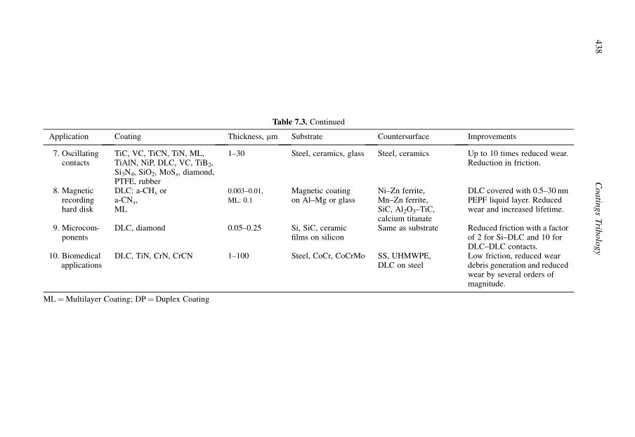
Table 7.3. Continued
Application Coating Thickness, mm Substrate Countersurface Improvements
7. Oscillatingcontacts
TiC, VC, TiCN, TiN, ML,TiAlN, NiP, DLC, VC, TiB2,Si3N4, SiO2, MoSx, diamond,PTFE, rubber
1–30 Steel, ceramics, glass Steel, ceramics Up to 10 times reduced wear.Reduction in friction.
8. Magneticrecordinghard disk
DLC: a-CHx ora-CNx,ML
0.003–0.01,
ML: 0.1
Magnetic coatingon Al–Mg or glass
Ni–Zn ferrite,Mn–Zn ferrite,SiC, Al2O3–TiC,calcium titanate
DLC covered with 0.5–30 nmPEPF liquid layer. Reducedwear and increased lifetime.
9. Microcom-ponents
DLC, diamond 0.05–0.25 Si, SiC, ceramicfilms on silicon
Same as substrate Reduced friction with a factorof 2 for Si–DLC and 10 forDLC–DLC contacts.
10. Biomedicalapplications
DLC, TiN, CrN, CrCN 1–100 Steel, CoCr, CoCrMo SS, UHMWPE,DLC on steel
Low friction, reduced weardebris generation and reducedwear by several orders ofmagnitude.
ML¼Multilayer Coating; DP¼Duplex Coating
43
8C
oa
ting
sT
ribo
log
y
their operating performance level, and may even self-repair. In the absence of such smart coatings, itwill be necessary to have advanced sensor technologies installed in tribological systems, to ensure thatthey are functioning effectively and to avoid catastrophic failure.
In the future a significant driver for coating development and the use of coated surfaces will be thetrend towards sustainable industrial production and a sustainable society. This includes requirementsfor improved environmental protection, better safety and reliability in combination with economicefficiency, including end-of-life disposal and reclamation.
The move away from toxic materials and environmentally damaging processes will thereforecontinue. This process of environmental and energy conservation and protection requires that the fulllifecycle impact of coatings and processes should be properly evaluated and acted upon. For example,a carburizing process to harden a gear might, during the hardening process, involve a significant CO2
emission, but if that allows a car to operate more efficiently throughout its life then the emissions atthe start might well be justified over the lifecycle.
Similarly, one might compare a modern high-strength case-hardened gear with one of equivalentpower transmission capacity but made from cast iron. The weight saved by using the smaller andlighter high-strength gear material, made possible by surface treatment, will more than compensatefor the energy which would have been consumed in carrying and moving the heavy large cast irongear. So, the message is that tribological treatments and coatings have the capability to have a majorimpact on energy and resource usage – but this requires the need to educate not only tribologicalprocess users but also politicians and others to avoid judgements, e.g., relating to legislation, whichare not in the overall interest of society.
We have mentioned in this book many application examples in which tribological coatings canprovide gains in efficiency and performance. Modern high-economy diesel engines could not functionreliably without carbon-based coatings applied to injector parts and advanced low-fuel consumptionaero-engines could not operate without effective thermal- and erosion-barrier coatings. The movetowards higher power densities for internal combustion engines, meaning smaller engines with higherpower outputs and increased efficiency, can only be achieved by the extensive use of high-perfor-mance tribological coatings.
While these comments are made primarily with mechanical parts in mind, there are other productsectors in which tribological coatings are having an increasing impact. In particular, the medical andhealthcare sector has a need to improve the lifetime and performance of implants and devices thatcome into contact with the body. In that case, reliability and safety are of absolute priority. Manyadvanced medical implant devices would fail without reliable biocompatible coatings which impartthe appropriate triboresponse with the body.
Coatings tribology is at the forefront of developments in most mission-critical components, re-gardless of the sector in which they have to operate. When the technological demands are coupledwith the economic imperative to reduce production costs and to improve reliability, it is clear that thechallenges facing tribologists and coating process developers are enormous. Nevertheless the payofffrom success in meeting these goals is huge with great societal impact, and it is our hope that this bookwill assist those who seek to achieve new solutions and breakthroughs.
439Applications

This page intentionally left blank

APPENDIX A

Tribology data sheet for coatings: Polymers and elastomers
Reference Coating Counterface
No. Year Authors Film Depositionmethod
Substrate Thicknessmm
Roughn./Hardn.Ra, mm/Hv
Material Roughn./Hardn.Ra, mm/Hv
1. 1988 Gladstone Silicon rubberSilicon rubberSilicon rubber
Siliconadhesive
Steel 300300300
0.25 GlassSiliconcoatingMetal
2. 1990 Adams Rubberycopolymers
Glass 4500 Hard rub. /
Soft. rub. /Glass
3. 1977 Fusaro Polyimide(PI)
Spraying þheating
Stainlesssteel 440C
25 0.01–1.3 Stainlesssteel 440C
4. 1978 Fusaro Polyimide(PI)
Sprayingþheating
Stainlesssteel 440C
25 0.9–1.3 Stainlesssteel 440C
5. 1981 Fusaro Polyimide(PI-4701)
Sprayingþheating
Stainlesssteel 440C
10–62 0.9–1.2 Stainlesssteel 440C
6. 1987a Fusaro Polyim. PMDA" 4701" 4701þ add.Polyim.PMDA" 4701" 4701þ add.
Sprayingþ heating
Stainlesssteel440C
25 0.9–1.2 Stainlesssteel 440C
7. 1988 SugimotoandMiyake
PTFEPTFE-PFPEPFPEPTFEPTFE-PFPEPFPE
Rfsputtering
Stainlesssteel
0.3 Stainlesssteel 440C
8. 1990 Yamadaet al.
PTFEPI
Sputtering Glass 0.05–1 Sapphire
9. 2004 Lee andLim
PTFEPTFEþnano-diamond fillers
Spraying Aluminium 30 Ball bearingsteel ball
10. 2005 Langladeet al.
PTFEþthermosetPTFEþfluorinated resin
Unknowncommercialmethod
32CrMoVa13steel
15–2220–30
100Cr6 steel
442 Coatings Tribology

Experiments Results
Geometry Speed m/s Load N Lubricationenvironment
Friction Wear, lifetime,debris wear rate,10�6$ mm3/Nm
Comments/Conclusions
Cyl.-on-plateReciprocating
0.01–0.15 40–80 Oil lubr. 0.006–0.060.02–0.060.02–0.03
Elastomer
Ball-on-plateCone-on-plate
0.15 0.01–0.50.010.01
Dry 0.31–0.450.5–11.5–4
Elastomerm increases withsharpness of cone forthick (500 mm) coatings
Ball-on-disk 1.6 10 Dry argonT z 100�C
0.03–0.23 m< 0.03 at T> 80�CFriction transitionindependent of speed
Ball-on-disk 2.6 10 Dry air /Dry argon /Moist air /
0.25–0.390.19–0.250.08–0.14
T¼ 25�C Transfer filmon ballIncrease in T givesdecrease in m in dryenvironment
Ball-on-disk 2.6 10 50% RH 0.08–0.22 Wear life proportionalto film thicknessDescription of wearmechanismsNo influence of filmthickness on m
Ball-on-diskB 4.76 mm
0.26 10 50% RH
Vacuum
0.41–0.480.11–0.180.13–0.180.35–0.450.050.05–0.1
905031000.59
Polyimid PMDA hashigh friction and lowwearin vacuum
Ball-on-diskB 6.35 mmReciprocal
0.0015 5 Air
Vacuum
0.18–0.380.15–0.230.15–0.20.18–0.450.15–0.450.2–0.6
Pin-on-disk 0.0004 0.5–10 Air 0.3
0.2
Film-likedebrisFlake-likedebris
m independent of loadand film thicknessPI had longer wear lifethan PTFE
Ball-on-plateReciprocating
0.01 0.8 AirAir at 150�C
0.160.08
Hard nanoparticlefillers in PTFE reducefriction and wear
Cyl.-on-plateReciprocating
5 Hz with�10 mmamplitude
Air 0.1–0.15
0.07–0.15
Wear depth: 1–2 mmafter 104 cyclesWear depth: 2–25 mmafter 104 cycles
Fretting test
443Appendix A
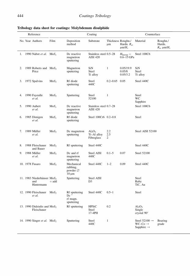
Tribology data sheet for coatings: Molybdenum disulphide
Reference Coating Counterface
No. Year Authors Film Depositionmethod
Substrate Thicknessmm
Roughn./Hardn. Ra,mm/Hv
Material Roughn./Hardn.Ra, mm/Hv
1. 1990 Nabot et al. MoSx Dc reactivemagnetronsputtering
Stainless steelAISI 420
0.5–28 Hknoop ¼0.6–15 GPa
Steel 100C6
2. 1989 Roberts andPrice
MoS2 Magnetronsputtering
SiNSteelTi alloy
1 0.05/19.90.05/80.05/3.2
SiNSteelTi alloy
3. 1972 Spalvins MoS2 Rf diodesputtering
Steel440C
0.2–0.65 0.05 Steel 440C
4. 1990 Fayeulleet al.
MoS2 Sputtering Steel52100
1 SteelWCSapphire
5. 1990 Aubertet al.
MoSx Dc reactivemagnetronsputtering
Stainless steelAISI 420
0.7–28 Steel 100C6
6. 1985 Dimigenet al.
MoSx Rf diodesputtering
Steel 100Cr6 0.2–0.8 Steel
7. 1989 Mulleret al.
MoS2 Dc magnetronsputtering
Al2O3
Ti–Al alloyFibreglass
2.22.52
Steel AISI 52100
8. 1988 Fleischauerand Bauer
MoS2 Rf sputtering Steel 440C Steel 440C
9. 1988 Mulleret al.
MoS2 Dc and rfmagnetronsputtering
Steel AISI440C
0.1–5 0.07 Steel 52100
10. 1978 Fusaro MoS2 Mechanicalrubbing,powder B
10 mm
Steel 440C 1–2 0.09 Steel 440C
11. 1983 NiederhanserandHintermann
MoS2
þ addSputtering Steel AISI
D3SteelRubyTiC, Au
12. 1990 Fleischaueret al.
MoS2 Rf sputteringDc "rf magn.sputtering
Steel 440C 0.5–1 Steel
13. 1990 Didziulis andFleischauer
MoS2 Rf sputtering HPSiCSteel17-4PH
0.2 Al2O3
Singlecrystal 90�
14. 1990 Singer et al. MoS2 Sputtering Steel440C
1 Steel 52100 /WC–Co /Sapphire /
Bearinggrade
444 Coatings Tribology

Experiments Results
Geometry Speedm/s
LoadN
Lubricationenvironment
Friction Wear, lifetime, debriswear rate,10�6 $ mm3/Nm
Comments/Conclusions
Ball-on-disk 0.01 5 Dry airLiquidnitrogen /
0.025–0.060.04
Low wear m< 0.05 for MoS1.5–MoS2.1
Increased humidity / increased mGood tribological propertiesin liquid nitrogen
Ball-on-disk 1.2 50 Vacuum 0.010.020.04
Life¼ 100,000 rev"¼ 10,000""¼ 500 "
m and life better for substrateSiN> steel> Ti alloyHigher roughness / lower frictionCoating method / tribological properties
Pin-on-disk 0.12–0.25
10/2.5/
Vacuum10�11 torr
0.020.04
Life¼ 38,000 rev"¼ 250,000 "Debrisagglomeration
No speed influenceSame composition as bulkMoS2 – no pinholes
Four ballB 12.3 mm
0.2 501.15–1.49 GPa
Air and Ar 0.02–0.04 2–3 timeslonger life inAr than in air
Longer lifetime for harder slidersStructure description of the slidingsurfaces
Ball-on-disk 0.01 5 Dry airRH< 5%
0.02–0.06 Increased m with smooth surfacesIncreased m with higher humiditym¼ 0.025 for Hk¼ 5 GPa and SiMo¼ 1.5
Ball-on-disk 4–200rpm
VacuumDry nitrogen
0.012–0.040.016–0.035
Smallest m in dry nitrogen withsulphur-deficient layers
Ball-on-disk 0.1 5 Humid air98% RH
Life: 100–400,000 rev.
": 11–12,000 rev." : 13–28,000 rev.
Little influence of h onlifetimeBest lifetime with Al2O3
substrate
Pin-on-disk 0.033 32 Drynitrogen
LubricationbyintercrystalliteslipOptimumcrystallitesize / maxwearlife
Pin-on-disk 0.1 5 Humid air98% RH
0.05 Life: 2000–1,000,000 rev.
Lifetime increases withthickness at h¼ 0.1–6 mm
Pin-on-disk 2.6 10 Dry airDry argonMoist air
0.01–0.020.01–0.020.08
Transfer film formed
Pin-on-disk 0.0003–0.12
0.2–60 RH< 20%20< RH< 97%97%< RH
0.02–0.3 Life: 0–4,005,000 rev.
Best results with MoS2–PTFEon chemically active Rh interlayerLoad and speed and humidityinfluence
Pin-on-disk 0.7 GPa Air Life: 45,000 rev." : 156,000 rev." : 200,000 rev.
Pin-on-flatOscillating3 mm
0.004 0.61.75 GPa
Vacuum10�5 torr
0.02–0.11
0.02–0.08
Life on SiC:150–450 cyclesLife on steel:1000 cycles
Better wear life with MoS2 onsteel than with MoS2 on SiC
Ball-on-diskB 1.6–12.7 mm
0.02 1–500.2–1.5 GPa
Dry airRH <1%
0.03–0.140.02–0.120.03–0.18
Friction coefficient is inversallyproportional to load
(Continued)
445Appendix A

Tribology data sheet for coatings: Molybdenum disulphide (Continued)
Reference Coating Counterface
No. Year Authors Film Depositionmethod
Substrate Thicknessmm
Roughn./Hardn. Ra,mm/Hv
Material Roughn./Hardn.Ra, mm/Hv
15. 1990 Kuwano MoS2
BþMoS2
BNþMoS2
TiB2þMoS2
Fast atombeamsputtering
Steel 440C
16. 1993 Miyoshiet al.
MoSx Magnetronsputtering
Steel 440C 0.11 0.009/6.8GPa
Steel 440C 0.007/8.5GPa
17. 1993 Wheeler MoSx Sputtering Steel 440C 0.11 0.016/6GPa
Steel 440C 0.008/8.5GPa
18. 1993 Ruff et al. MoS2 Dc sputteringRf sputteringMagnetronsputteringMultilayersputtering
Steel 440C 1–5 0.15/58HRC
Au, Ni, Mo,Ti, Cu,bronze, PTFE,polyimide,differentcompositions
0.5
19. 1993 Matrin et al. MoS2
S:Mo-ratio¼ 2.04
Rfmagnetronsputtering
SteelAISI52100
0.12 H¼ 7.8GPAE¼ 165–170 GPa
Steel
20. 1998 Gilmoreet al.
TiN–MoS2 Dcmagnetronco-sputtering
Stainlesssteel
0.5–3 Steel
21. 1999 Wahl et al. Pb–Mo–Samorphous
Dualion-beamdeposition(IBD)
Steel 0.2–0.51 Steel 52100
22. 2003 Zhang et al. MoS1.3
basal planeorientationMoS1.8
randomorientation
Planarmagnetronsputtering
Stainlesssteel440C
Ra¼ 0.05mm
Corundum Ra¼ 0.05mm
23. 2004 Steinmannet al.
MoS2–C–TiB2
Non-reactivedc magnetronsputtering
Steel Rz¼ 0.08mm
Steel100Cr6
24. 2005 Amaro et al. MoS2 –Ti Dc magnetronsputtering
1200SiC steel
1.22 M42polished
Steel
446 Coatings Tribology
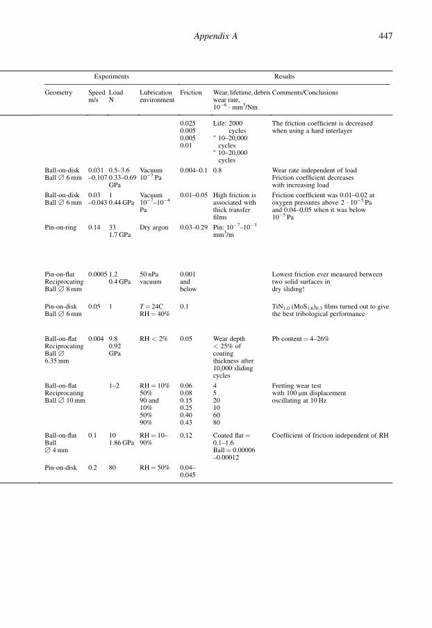
Table Continued
Experiments Results
Geometry Speedm/s
LoadN
Lubricationenvironment
Friction Wear, lifetime, debriswear rate,10�6 $ mm3/Nm
Comments/Conclusions
0.0250.0050.0050.01
Life: 2000cycles
" 10–20,000cycles
" 10–20,000cycles
The friction coefficient is decreasedwhen using a hard interlayer
Ball-on-diskBall B 6 mm
0.031–0.107
0.5–3.60.33–0.69GPa
Vacuum10�7 Pa
0.004–0.1 0.8 Wear rate independent of loadFriction coefficient decreaseswith increasing load
Ball-on-diskBall B 6 mm
0.03–0.043
10.44 GPa
Vacuum10�7–10�4
Pa
0.01–0.05 High friction isassociated withthick transferfilms
Friction coefficient was 0.01–0.02 atoxygen pressures above 2 $ 10�5 Paand 0.04–0.05 when it was below10�5 Pa
Pin-on-ring 0.14 331.7 GPa
Dry argon 0.03–0.29 Pin: 10�7–10�3
mm3/m
Pin-on-flatReciprocatingBall B 8 mm
0.0005 1.20.4 GPa
50 nPavacuum
0.001andbelow
Lowest friction ever measured betweentwo solid surfaces indry sliding!
Pin-on-diskBall B 6 mm
0.05 1 T¼ 24CRH¼ 40%
0.1 TiN1.0 (MoS1.6)0.3 films turned out to givethe best tribological performance
Ball-on-flatReciprocatingBall B
6.35 mm
0.004 9.80.92GPa
RH < 2% 0.05 Wear depth< 25% ofcoatingthickness after10,000 slidingcycles
Pb content¼ 4–26%
Ball-on-flatReciprocatingBall B 10 mm
1–2 RH¼ 10%50%90 and10%50%90%
0.060.080.150.250.400.43
4520106080
Fretting wear testwith 100 mm displacementoscillating at 10 Hz
Ball-on-flatBallB 4 mm
0.1 101.86 GPa
RH¼ 10–90%
0.12 Coated flat¼0.1–1.6Ball¼ 0.00006–0.00012
Coefficient of friction independent of RH
Pin-on-disk 0.2 80 RH¼ 50% 0.04–0.045
447Appendix A

Tribology data sheet for coatings: Soft metals
fPrivategReference
Coating Counterface
No. Year Authors Film Depositionmethod
Substrate Thicknessmm
Roughn./Hardn. Ra,mm/Hv
Material Roughn./Hardn. Ra,mm/Hv
1. 1950 Bowdenand Tabor
Lead Copper 0.03–30 Steel
2. 1985 Gerkema Lead Sputtered Steel 0.1–0.2 0.05/0.28/0.46/
Pb-coatedsteel
0.05
3. 1991 Liu et al. Lead Brushplated
Steel Steel
4. 1977 SherbineyandHalling
Lead /Silver /Indium /
Ion plating Steel ball(EN31)
0.01–10 0.75 Steel disk
5. 1978 ArnellandSoliman
Lead /Silver /Indium /
Ion plating Steeldisk(EN31)
0.1–10 0.025–0.7 Steel
6. 1976 Jahanmiret al.
Cadmium /Silver /Gold /Nickel /
Steel (AISI1018,1095and 4140)
1(0.05–10)
0.4/1700MPa(840–4600MPa)
Steel
7. 1990 Erdemiret al.
Silver Ion-assisteddeposition
Al2O3 0.5–2 0.3 Al2O3 0.03
8. 1991 Tian et al. Gold (Niinterlayer)
Electroplated Brass 1.5Ni¼ 2.5
GoldcoatingonNi–Brass
9. 1950 Bowdenand Tabor
Indium Tool steel 0.01–30 Steel
10. 1989 Gawneand Ma
Chrom. /Nickel /Chrom. /Nickel /
Electroplated Steel 40 0.25
0.5–0.6
Steel– " –Diamond– " –
0.25
11. 1991 Ajayiet al.
Silver IBAD Si3N4 1 0.072 GPa Si3N4 /17.41GPa
12. 1991a Erdemiret al.
Silver IBAD ZrO2þ5%CaO
2 0.2 ZrO2
þ 5%CaO0.03/15Hk
448 Coatings Tribology

fPrivategExperiments
Results
Geometry Speedm/s
Load N Lubricationenvironment
Friction Wear, lifetime,debris wear rate,10�6 $ mm3/Nm
Comments/Conclusions
Ball-on-flatB 6 mm
Dry 0.3 h¼ 30 mm / minimum m¼ 0.3Softer substrate needs thicker film
Pin-on-diskBall B 5 mm
0.025 5(2.5, 10)
Vacuum5 $ 10�7 torrT¼ 25–300�C
0.080.100.16
Filmlife:3–1300 m9–10,000 m4–11,000 m
Increase in m with surface roughnessLoad (2.5–10 N) influence / m verysmallIncreased load / decreased endurance
Ball-on-disk 0.15–3.75
10–3000 LubricatedParaffin oil
0.05–0.09
Higher hardness / lower m andimproved VNo thickness influence
Pin-on-disk 0.04–1.2 5–40 Dry 0.1–0.60.15–0.50.05–0.5
Life: 500 rev.150 "150 "
Best lifetime for PbLoad, speed and thickness effectsFilm thickness m min w h¼ 0.5–1 mm
Pin-on-diskB 3 mm
0.01 1 Vacuum10�8 torr
0.1–0.20.1–0.20.2–0.3
Increase in m with h and Ra
Increase in m with speed
Cylinder-on-cylinderB 6.3 mm
0.03 22.5 Argon 0.25–0.350.330.85–0.9–
1.8 $ 10�8 mg/cm– " –– " –Imediatefailure
Optimum thickness¼ 1 mm
Pin-on-diskB 9.5 mm
1 50.8 GPa
Dry air 0.4–0.9 Reduce wear rate and friction inAl2O3–Al2O3 contacts
Ball-on-flatReciprocatingB 3.2 mm
0.004 1 Dry air /Polyphenyletherlubrication /
0.3–1.2
0.1
Wear mechanisms described
Ball-on-flatB 6 mm
40 Air 0.08–0.35 Minimum m at h¼ 0.1–1 mm
Pin-on-cylind.FalexScratch-testReciprocating
0.1
0.04
225
20
Air 0.68–0.880.90–1.20.03–0.50.06–0.3
No correlation between coatinghardness and wearConventional chromium has lowestwear
Pin-on-diskReciprocating
0.05 3–10 Air, T¼ 23�CRH¼ 40–45%
0.15–0.75 0.1 Friction coefficient reduced by 50% andwear rate by 1–2 orders of magnitudecompared to uncoated contacts
Pin-on-diskBall B 9.5 mm
0.1–2 50.46 GPa
Air, T¼ 23�CRH <1%
0.2–0.45 Ball: 0.38Disc:unmeasurable
Friction coefficient reduced by 50% andwear rate by several orders ofmagnitude compared to uncoatedcontacts
(Continued)
449Appendix A

Tribology data sheet for coatings: Soft metals (Continued)
fPrivategReference
Coating Counterface
No. Year Authors Film Depositionmethod
Substrate Thicknessmm
Roughn./Hardn. Ra,mm/Hv
Material Roughn./Hardn. Ra,mm/Hv
13. 1991b Erdemiret al.
Silver IBAD MgO–PSZ 1.5 0.2/0.25GPa
MgO–PSZ 0.03/11
14. 1992 DellaCorteet al.
Silver Sputtered Al2O3 1.5 0.1 Al2O3 /20
15. 1986 El-Sherbinyand Salem
Silver Ion plating SteelEn-31 balls
1.5 0.75 SteelEN-31plate
16. 1992 Sander andPetersohn
Silver /Indium /Copper /Lead /
PVD TiN coatedsteel(100Cr6)
<5 Steel(100Cr6)
17. 2003 Yang et al. Silver withhardultra-thinsilverbondlayer
IBAD andthermalevaporation
AISI52100steel
2 0.02/57–61HRC
AISI52100steel
55–60HRC
18. 2004 Lince GoldAuþMoS2
Sputtering 440C steel 0.260.11
0.03 440C steel 0.01–0.03
450 Coatings Tribology
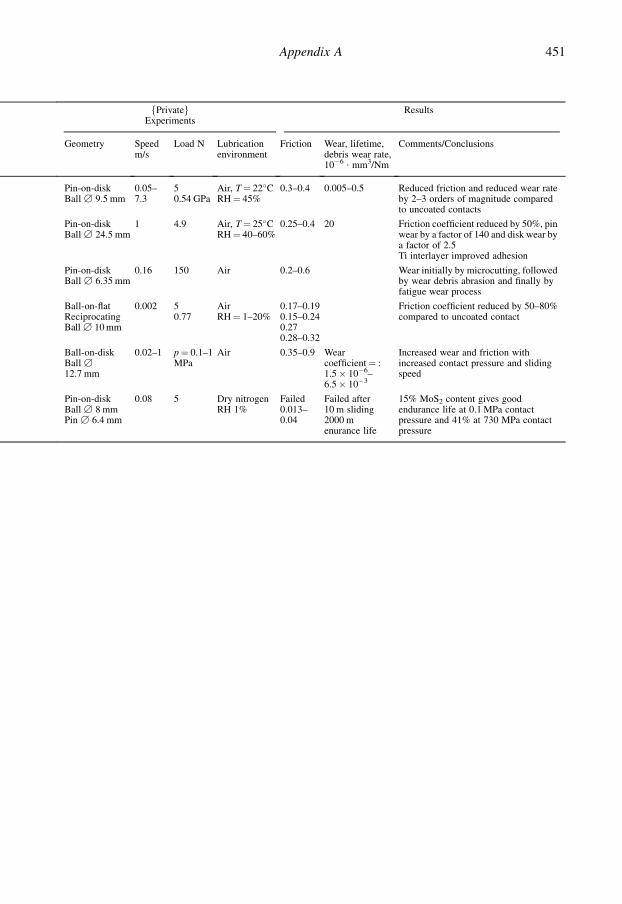
Table Continued
fPrivategExperiments
Results
Geometry Speedm/s
Load N Lubricationenvironment
Friction Wear, lifetime,debris wear rate,10�6 $ mm3/Nm
Comments/Conclusions
Pin-on-diskBall B 9.5 mm
0.05–7.3
50.54 GPa
Air, T¼ 22�CRH¼ 45%
0.3–0.4 0.005–0.5 Reduced friction and reduced wear rateby 2–3 orders of magnitude comparedto uncoated contacts
Pin-on-diskBall B 24.5 mm
1 4.9 Air, T¼ 25�CRH¼ 40–60%
0.25–0.4 20 Friction coefficient reduced by 50%, pinwear by a factor of 140 and disk wear bya factor of 2.5Ti interlayer improved adhesion
Pin-on-diskBall B 6.35 mm
0.16 150 Air 0.2–0.6 Wear initially by microcutting, followedby wear debris abrasion and finally byfatigue wear process
Ball-on-flatReciprocatingBall B 10 mm
0.002 50.77
AirRH¼ 1–20%
0.17–0.190.15–0.240.270.28–0.32
Friction coefficient reduced by 50–80%compared to uncoated contact
Ball-on-diskBall B
12.7 mm
0.02–1 p¼ 0.1–1MPa
Air 0.35–0.9 Wearcoefficient¼ :1.5� 10�6–6.5� 10�3
Increased wear and friction withincreased contact pressure and slidingspeed
Pin-on-diskBall B 8 mmPin B 6.4 mm
0.08 5 Dry nitrogenRH 1%
Failed0.013–0.04
Failed after10 m sliding2000 menurance life
15% MoS2 content gives goodendurance life at 0.1 MPa contactpressure and 41% at 730 MPa contactpressure
451Appendix A

Tribology data sheet for coatings: Titanium nitride coatings
fPrivategReference
Coating Counterface
No. Year Authors Film Depositionmethod
Substrate Thicknessmm
Roughn./Hardn. Ra,mm/Hv
Material Roughn./Hardn.Ra, mm/Hv
1. 1983 Sundquistet al.
TiN Ion plating Steel40CrMoVo51
4 Mild steel
2. 1987 Matthewset al.
TiNTiNTiN
Ion plating HSS 1 0.06 Tool steelTiCCopper
3. 1980 Jamalet al.
TiN ARE Stainless steel304C
4–8 0.3 SteelTiC/440CTiN/440CAl
0.1
4. 1980 Habiget al.
TiN CVD Steel205CrWMoV
3 0.9 Steel 1.7
5. 1989 Peeblesand Pope
TiN Reactiveevaporation
Steel 304SS Steel 440CSS
6. 1990 Knightet al.
TiN PVDsputteringevaporativeCVD
Steel 835M30
Steel 835M30
2
2–5
0.14–0.88
0.65–0.88
Diamond
7. 1987 Shimazkiand Winer
TiN Sputteringrf/reactivePVD
Tool steel 0.1–2.7 0.28–0.9 Steel
8. 1990 Sueand Troue
TiN PVD arcevaporation
Steel ringAISI 4620
10 0.1 Steel AISI 01Block
0.25–0.3
9. 1990 Kennedyand Tang
TiNþ Ti
PVDarcevaporation
Steel Inconel625
25 Carbon graphite
10. 1990 Bull et al. TiN PVDsputtering
Stainless steel 5 SteelTiN
11. 1981 Hintermann TiN CVD Steel 0.1 SteelTiCTiN
12. 1989 Gardos TiN TiN
13. 1985 Makelaand Valli
TiN PVD SteelHSSPin
0.6–0.8 0.05–0.09 Tool steelTiNTiC
0.05–0.09
14. 1979 Suri et al. TiN Bias activatedreactiveevaporation
Stainless steel /Aluminium /Titanium /
4–6 Stainlesssteel 440C
15. 1990 Habig TiN CVD X205CrWMo121
3 Rz¼ 1 mm TiN on Rz¼ 1 mm
452 Coatings Tribology

fPrivategExperiments
Results
Geometry Speedm/s
Load N Lubricationenvironment
Friction Wear, lifetime,debris wear rate,10�6 $ mm3/Nm
Comments/Conclusions
Pin-on-disk 0.2 0.5–10 Dry 0.2 at 0.5 N0.4 at 1 N0.7 at 10 N
2–10 timesincreased lifetime
Increase of friction with loadDecreased wear even after failureFriction for St w St m¼ 0.7
Pin-on-disk 0.2 5 Dry 0.15–0.20.7
2.82.1
Influence of counterface material
Pin-on-disk 0.1 40 Dry 0.750.20.45
Low m and w with hard wearcouplesAl does not support hard coatingsLubrication decreased m
Pin-on-disk 0.1 2.5550–500
DryDryLubr.
0.17–0.210.1–0.380.1–0.06
0.760.2–
m¼ 0.38 after coating failure
Pin-on-platePin B 0.8,15 and 54 mm
0.025 64 MPa150 MPa1060 MPa0.33 N
0.17–0.24
0.15
No influence of pressure on m or wTi underlayer improves w but mis the sameVacuum / rapid failure
Scratch testStylus B
100–200 mm
0.0005 0.25–10 Dry 0.20.2–0.35
m increases with load
Pin-on-flatReciprocatingPin B 0.25 in
0.0025Amplitude2 cm
0.67 ~550 MPa4.6 ~1000 MPa
Dry 0.6–0.9Uncoated¼0.45–0.85
Formation of transfer layerTiN m higher than for uncoatedInfluence of h on m
Block-on-ringReciprocating
0.07 1090 Dry 0.62–0.67 Reduced wear by5 timesAggomer. a-Fe2O3
debrisLittle Ti2O
Surface oxidationAbrasive and oxidative wearTransfer layer on steel
Ring-on-ring‘Drill pressconverted’
4.7 50 ~ 125kPa100 ~ 250kPa
Dry Spalling Transfer film of carbonNo influence of h on w
Pin-on-diskBall B 3 mm
0.075 2.5 0.3–0.70.1–0.7
1–10,000 Wear mechanisms: adhesion,oxidation, abrasion Infl. v /w:<0.11 m/s no influence;>0.11 increaseInfluence on microstructure / w
Pin-on-disk 0.01 5 Dry 0.490.16–0.310.19
1010.5
Counterface influence
Formation of TiO2 layer
Pin-on-disk 0.2 5 Dry 0.6–0.90.10.15–0.7
0.5–50.22
Both pin and disk coated anduncoated /Influence of geometryFriction curves
Pin-on-disk120� coneTip B 0.125 mm
0.2–0.23 4 Dry 1.150.920.92
Lubrication decreased m to0.175–0.225
Pin-on-disk 0.1 2.5 Air, 50%RH Vacuum
0.20.5
Friction depends strongly onthe oxygen pressure ofthe environment
(Continued)
453Appendix A
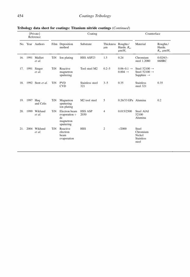
Tribology data sheet for coatings: Titanium nitride coatings (Continued)
fPrivategReference
Coating Counterface
No. Year Authors Film Depositionmethod
Substrate Thicknessmm
Roughn./Hardn. Ra,mm/Hv
Material Roughn./Hardn.Ra, mm/Hv
16. 1991 Mallietet al.
TiN Ion plating HSS ASP23 1.5 0.24 Chromiumsteel 1.2080
0.02/63–66HRC
17. 1991 Singeret al.
TiN Reactivemagnetronsputtering
Tool steel M2 0.2–5 0.06–0.1 /0.004 /
Steel 52100 /Steel 52100 /Sapphire /
18. 1992 Stott et al. TiN PVDCVD
Stainless steel321
3–5 0.35 Stainlesssteel 321
0.35
19. 1997 Huqand Celis
TiN Magnetronsputteringion plating
M2 tool steel 5 0.26/33 GPa Alumina 0.2
20. 1999 Wiklundet al.
TiN Electron beamevaporationþdcmagnetronsputtering
HSS ASP2030
4 0.015/2500 Steel AIAI52100Alumina
21. 2004 Wiklundet al.
TiN Reactiveelectronbeamevaporation
HSS 2 –/2000 SteelChromiumNickelStainlesssteel
454 Coatings Tribology

Table Continued
fPrivategExperiments
Results
Geometry Speedm/s
Load N Lubricationenvironment
Friction Wear, lifetime,debris wear rate,10�6 $ mm3/Nm
Comments/Conclusions
Pin-on-diskBall B 10 mm
0.163 0.5–13 Air, T¼ 22�CRH¼ 52%
0.55–1.15 0.1–0.8
Ball-on-flatUnidirectionalBall B 3.2–12.7 mm
0.0001 10 AirRH¼ 30%
0.5–0.70.15–0.20.05–0.15
Higher friction coefficientscorrespond to rougher surfacesand more debris inthe wear track
Pin-on-diskBall B 50 mmReciprocating
0.001 16.3 Carbon dioxide20�C /300�C /500�C/
0.20.40.6
Increased friction coefficient withincreased temperaturein carbon dioxide environment
Pin-on-diskUnidirectionalBall B 10 mm
0.1 m/s 3–24 Dry 0.9–1.2 5–20
Ball-on-diskUnidirectionalBall B 5 mm.
0.05 5 Dry 0.51.1
Disc: �25;Ball: 40Disc: 3;Ball: 0.1
Ball-on-diskUnidirectionalBall B 6 mm
0.01 30 Dry On St: 0.6
On Cr: 0.7On Ni: 0.35
On SS: 0.65
Initial friction 0.2 up to 20revolutionsInitialfriction0.2upto4revolutionsInitial friction immediatelyincreasing from 0.2Initial friction immediatelyincreasing from 0.2
455Appendix A

Tribology data sheet for coatings: Nitrides (LTiN excluded)
fPrivategReference
Coating Counterface
No. Year Authors Film Depositionmethod
Substrate Thicknessmm
Roughn./Hardn. Ra,mm/Hv
Material Roughn./Hardn.Ra, mm/Hv
1. 1990a Ronkainenet al.
(Ti,Al)N Ion plating SteelASP23
2–8 0.04 Steel M50
2. 1990 Roos et al. (Ti,Al)N PVD SteelHSS
3.5 SteelCr5020
3. 1990a Bull andRickerby
CrN Ion plating Steel 2–9 Steel
4. 1987 Miyoshiet al.
BN Ion beamdep. PVD
Silicon,SiO2,GaAs,InP
0.1 DiamondTip B
0.4 mm
5. 1989 Miyoshi BN Ion beamdep. PVD
Stainlesssteel 304and 440CTi
6. 1988 Elena et al. BN Rfmagnetronsputtering
WC–Co 1 DiamondTip B
0.4 mm
7. 1989 Inagawaet al.
C–BN Reactiveevaporation
Silicon 0.4 Stainlesssteel
8. 1990b Ronkainenet al.
Ti(B,N) EB PVDrf magn.sput.
SteelASP23
58
0.04 Steel M50
9. 1990 Roos et al. (Ti,Nb)N PVD SteelHSS
5.5 SteelCr5020
10. 1992 Coll et al. (Ti,Al)N Arcevaporation
SteelHSS M2Ball
4 Steel diskAISI 4135
11. 1993a Vancoilleet al.
(Ti,Al)N /(Ti,Nb)N /Ti(C,N) /
Ion plating SteelHSS M2
2–2.5 0.01 Corrundum(a-Al2O3)
0.2
12. 1991 Watanabeet al.
C–BN /a-BN /h-BN /
Ion plating Siliconwafer
SS 440C 0.1/4.3GPa
13. 2001 Podgornik TiAlN PVD HardenedAISI4140 steelNitrided AISI4140 steel
4
4
0.4/1500 Hv
0.4/1900 Hv
AISI 52100steel
�/700
14. 2003b Tuszynskiet al.
CrNTi(C,N)Cr(C,N)
Vacuumarc PVD
Steel 222
0.05/2000 Hv
0.05/3100 Hv
0.05/2300 Hv
Al2O3
15. 2004 Wiklundet al.
VN Reactiveelectronbeamevaporation
High-speedsteel
1.1 �/1100 Hv Steel
Chromium
Nickel
Stainless steel
456 Coatings Tribology

fPrivategExperiments
Results
Geometry Speedm/s
LoadN
Lubricationenvironment
Friction Wear, lifetime, debriswear rate, 10�6 $mm3/Nm
Comments/Conclusions
Pin-on-diskBall B
10 mm
0.1 10 Dry 0.7–0.9 Pin: 3Disc: 25–60
Pin-on-diskBall B 10 mm
0.4 4 Dry Pin: 2� TiN
Pin-on-diskBall B 3 mm
0.1 2.75 Dry 0.6–0.8 Disc: 10(0.1)
Good abrasive wear resistanceTransfer layer on ball
Scratch testSingle passDist. 10 mm
0.0002 1–155–25GPa
Dry 0.05–0.2 Elastic and plastic deformationBN film is amorphous
Scratch testSingle passDist. 10 mm
0.0002 1–155–25GPa
Dry 0.08–0.12
Scratch testSingle pass
2–20 Dry 0.05–0.3
Ring-on-disk 10 0.35 m¼ 0.05 in vacuum and 400�C
Pin-on-diskBall B
10 mm
0.1 10 Dry 0.68–0.780.6–0.9
Pin: 0.8Disc: 10–20
Pin-on-diskBall B 10 mm
0.4 4 Dry Pin¼ 3� TiNzTiAlN
Pin-on-diskBall B
30 mm
0.5–5 2 Dry, RH¼ 50%
0.37–0.74
Pin: 0.37–1.24
Pin-on-diskBall B
10 mm
0.1 5 Dry, T¼ 25�CRH¼ 50–70%
1.0–1.40.9–1.40.1–0.4
Wear decreases with increasingspeed
Ball-on-flatReciprocalBall B 6.35 mm
0.0017 5 DryRH¼ 50–60%
0.30.8–1.00.8–1.0
C–BN has lesswear than a-BNand h-BN
Pin-on-disk 1 60 Dry Pin: 1Pin: 0.5–0.8
Coated pin sliding against steeldisk
Ball-on-flatBall B
10 mm
0.1 10 DryRH¼ 50%
0.830.330.82
Disc: 0.03Disc: 200Disc: 1
The wear debris was removedfrom the contact continuously bya draught of dry argon
Ball-on-diskUnidirectionalBall B 6 mm
0.01 30 DryRH¼ 40%
St: 0.6
Cr: 0.6
Ni: 0.27
SS: 0.65
Initial friction 0.2 up to 20revolutionsInitial friction 0.2 up to 4revolutionsInitial friction immediatelyincreasing from 0.2Initial friction immediatelyincreasing from 0.3
457Appendix A

Tribology data sheet for coatings: Carbides
fPrivategReference
Coating Counterface
No. Year Authors Film Depositionmethod
Substrate Thicknessmm
Roughn./Hardn. Ra,mm/Hv
Material Roughn./Hardn. Ra,mm/Hv
1. 1981 Hintermann TiC
SiC
Cr7C3
CVD
CVD
CVD
Steel
Steel
Steel
0.1
0.1
0.1
SteelTiCTiNAlOSiCSiCSteelSteel
2. 1960 Mordike WCTiCTaCTiCNbCBC
WCWCTaCGraphiteNbCBC
3. 1987 BovingandHintermann
TiC CVD Steel 4 Steel52100
4. 1987 Matthewset al.
TiC(ball)
Ion platingPVD
Steel Tool steelTiN onsteel
58HRC
0.02–0.04Ra
5. 1990 Knightet al.
TiC CVD Steel 5 1700–2000 Diamondstylus
6. 1980 Jamalet al.
TiC Activatedreactiveevaporation¼ARE
Steel440C ball
4–8 0.3/2800–3000
SteelTiCTiNTiC/TiTietAlTiNþ Ti2N/TiTiþ TiC/AlTiNþ Ti2N/Al
0.1/3002800–30001800–2000
7. 1980 Habig et al. TiCCrxCy
CVD"
Steel62HRC
510
1/20001/1500
Steel– " –
1.71.7
8. 1979 Suri et al. TiC Biasactivatedreactiveevaporation
StainlesssteelAluminiumTitanium
4–6 0.1/3000 Stainless steel 0.1/300
9. 1989 Farges et al. WC +Cr subl.
PACVD Tool steel 16 SteelTiNþ steel
52HRC
10. 1988 Srivastavaet al.
WC Rf reactivemagnetronsputtering
Stainlesssteel
7 3200 Stainless steel
11. 1987 Lindgrenet al.
CrC Detonationgunplasmagun
~20–100
12. 1988 Rey BC CVD Graphite BCSteel 42CD4SiCAlOSi3N4
ZrO
13. 1990 Habig TiC CVD SteelX205CrWMo121
5 2.7 TiC coatedsteelX205CrWMo121
62HRC
458 Coatings Tribology

fPrivategExperiments
Results
Geometry Speedm/s
Load N Lubricationenvironment
Friction Wear, lifetime, debriswear rate, 10�6 $mm3/Nm
Comments/Conclusions
Pin-on-disk 0.01 5 Dry 0.250.22–0.320.25–0.310.190.25–0.350.27–0.470.230.79
Disc: 1.5Disc: 3Disc: 5Disc: 2Disc: 2–7Disc: 4–8Disc: 0.5–0.7Disc: 15
Ring-on-ring 0.03 0.0025–0.3
Dry 0.180.20.20.150.20.12
All carbides similar mIncrease in m after~1000�CBulk carbides!
Pin-on-disk DryHumidVacuum
0.30.20.3
No influence ofvacuumFormation of TiO2
improves friction
Pin-on-diskBall B 50 mm
0.2 5 0.3–0.40.15–0.2
Coated pin 0.4" " 0.9
TiC sliding againstTiN 0 low friction
ScratchTipB 0.1–0.25 mm
0.0005 0.25–10 0.2–0.25 m increased with loadm depends on plasticflow
Pin-on-disk 0.1 40 Dry 0.50.20.20.1750.8–0.850.20.30.35
HighLowMediumLowHighLowHighHigh
Influence ofcounterfaceLubrication decreasedm
Pin-on-disk"
0.1"
2.5–5"
Dry (lubr.)"
0.11–0.160.24–0.51
0.63–4
No running-in wear/Lubr. m¼ 0.09–0.105Higher wear/Lubr.m¼ 0.06–0.1
Pin-on-disk 0.2 4 Dry (lubr.) 0.70.91.07
LowMediumMedium
High friction and lowwear
Pin-on-diskBall B 20 mm
0.015 1 Dry 0.3–0.40.25–0.5
LowLow
Pin wear reduced bypolishing but notfriction
Pin-on-disk 0.158 100 Lubr. SAE30Mobil oil
0.09–0.25 Minimum withh¼ 1–2 mm
Coating thicknessinfluence on wear
Pin-on-diskReciprocating
0.007–0.7
0.7–7MPa
T¼ 20–800�C 0.4–0.6 Different coatingcompositions andatmospheres
Pin-on-diskReciprocating
0.0016 10 Dry 0.150.2–0.40.2–0.30.2–0.40.25–0.350.2–0.35
Not major influence ofcounterfaceBC/BC besttribocombination
Pin-on-disk 0.1 2.5 Air Rh¼ 50% /Vacuum /
0.20.5
Main wear mechanismsare polishing,tribooxidation andadhesion
459Appendix A

Tribology data sheet for coatings: Oxides and borides
fPrivategReference
Coating Counterface
No. Year Authors Film Depositionmethod
Substrate Thicknessmm
Roughn./Hardn.Ra, mm/Hv
Material Roughn./Hardn.Ra, mm/Hv
1. 1981 Hintermann Al2O3 CVD Cementedcarbidetool
Steel100Cr6TiC
2. 19871988
Roth et al. Al2O3 Rf magnetronsputtering
Cast iron 4 0.36/300HV
0.05Steel155CrVMo121
0.26/1000Hv
3. 1987 Matthewset al.
Ti–O Ion plating HSS ball 2 0.06/2000–2400Hk
SteelCopper
58HRC80Hv
4. 1987b Fusaro CdO Sputtering Steel 0.05–0.1 Steel
5. 1988 Levy TiB2 CVD WC–Co 30–40
6. 1981 Hintermann FexB CVD Cementedcarbidetools
SteelCr6 pin
7. 1980 Habig et al. Fe2B CVD Cementedcarbidetools
Fe2B
8. 1990 Habig TiB2 Thermochemicaltreatment
Ti–6%Al–4%V
30 2.8 TiB2
coatedTi–6%Al–4%V
460 Coatings Tribology

fPrivategExperiments
Results
Geometry Speedm/s
LoadN
Lubricationenvironment
Friction Wear, lifetime, debriswear rate, 10�6 $mm3/Nm
Comments/Conclusions
Pin-on-disk 0.01
0.01
0.01
20
20
5
Dry
"
"
0.45
0.19
0.62
Disc: 75Pin: 0.5Disc: 0.5Pin: 0.005Disc: 0.36Pin: 0.66
Al2O3 sliding against TiC 0low wear and friction
Plate-on-cylinder
0.04 100Pa
Dry Low wearcompared touncoated
Pin-on-disk 0.2 5 Dry 0.2–0.350.5–0.65
Pin: 0.8 Coating wear ~TiN and TiC
Pin-on-disk 0.26 10 Dry 0.17–0.23 0.1
0.17 MPa T¼ 19–36�CT¼ 540�C
0.62–0.821.06
Extremely lowcompared toplasma sprayed
Very low wear
Pin-on-disk 0.01 5 0.76 Disc: 0Pin: 12
Pin-on-disk 0.01 5 0.40 0.06 Extremely low wear <TiNand TiC
Pin-on-disk 0.1 2.5 Air RH¼ 50% /Vacuum /
0.4–0.60.75
Wear volume was six timeshigher than for TiN
461Appendix A

Tribology data sheet for coatings: Diamond and diamond coatings
fPrivategReference
Coating Counterface
No. Year Authors Film Depositionmethod
Substrate Thicknessmm
Roughn./Hardn.Ra, mm/Hv
Material Roughn./Hardn.Ra, mm/Hv
1. 1973 Caseyand Wilks
– – Naturaldiamond
– Oriented Naturaldiamond
Oriented
2. 1981 Mehanand Hayden
PCD Highpressure
CementedWC
500 0.1–0.20.3–0.73
St.4620St.Ni12Cr
0.20.76
3. 1988 Yust et al. TiB2 Ionimplantation
Diamond
4. 1990 Haywardand Singer
DC mwave CVD Singlecrystalsilicon
1 0.001–0.35
SCDSapphire
5. 1989 Jahanmiret al.
DC HFCVD SiC 2.5–4.3 SiC
6. 1990 Blau et al. DC HFCVD Siliconwafer
Pyramidal,m-crystalplate
St52100sapphire
7. 1989 Wong et al. DC mwave CVD Si, Mo. 0.047–0.094
Steel
8. 1990 Gardosand Soriano
DC PACVD a-SiC 1.5 0.1 DC ona-SiC /a-SiC /
0.1
9. 1990 Kohzakiet al.
DC Hot filamentCVD
SiC 10 0.02/80 GPa
SiC
10. 1992 Miyoshiet al.
––DCDC
––mwave CVDmwave CVD
NaturaldiamondNaturaldiamondSiCSiC
––0.5–1.5 0.013
Diamond /Si3N4 /Diamond /Si3N4 /
11. 1992 Fengand Field
– – Diamond – Diamond
12. 1993a and b
Mohrbacheret al.
DC Hot filamentCVD
WC–Co(KIO)
1 0.97 DC /a-Al2O3 /Cr-steel /WC–Co /
462 Coatings Tribology

fPrivategExperiments
Results
Geometry Speedm/s
LoadN
Lubricationenvironment
Friction Wear, lifetime,debris wear rate,10�6 $ mm3/Nm
Comments/Conclusions
Stylus planeOscillating
1–100$ 10�6
0.03–3 Dry and oil 0.04–0.11 No lubricant speed, loadinfluenceOrientation influence
Block ringRotating
0.1 223341 MPa
Dry /Oil /
0.1–0.70.05–0.1
Stylus diskRotating
2.5 $ 10�3 Dry 0.01–0.04 Formation of a carbon layer
Stylus planeOscillating– " –
0.3 $ 10�3
– " –2–5
– " –
Dry
– " –
0.05–0.5
0.1–0.6
Strong topography influenceDC¼ diamond coatingSCD¼ single crystal diamond
Ball-on-3-flat 38 $ 10�3 ~40Increasing
Dry 0.08 Much debris Graphitization
Scratch 5 strokes Dry 0.2–0.6 Much debris
Block ringRotating
1 54 Mineral oil 0.035–0.04
Pin-on-flatOscillating
0.0047 0.492900 MPa
VacuumAir, 50%RH Vacuum
0.10.150.1
0.4130
Friction measured at roomtemperatureTest temperature cycle: 25�C,850�C, 25�C
Ball-on-diskBall B 2.5 mm
0.04–0.08 4.9 0.09 Ball: 0.002Disc: non-detectable
Smooth surfaces gives lowfriction
Ball-on-flatReciprocatingBall B 1.3–1.6 mm
0.0014 1 Air, 40% RH 0.010.030.090.1
0.20.20.050.05
No humidity effect on frictionand wear in diamond–diamondor diamond–DC contactsMoisture increased friction inSi3N4–diamond and Si3N4–DCcontacts
Stylus planeOscillating
0.0001–0.0002
1 Air 0.08 Most wear debris ishydrocarbonThere is little graphite but nodiamond
Ball-on-flatBall B 10 mm
0.001 1–6 Air, 22�C50–60% RH
0.050.050.5–0.60.5
Transfer layers and high frictionin DC–WC–C and DC–Cr steelcontacts
(Continued)
463Appendix A

Tribology data sheet for coatings: Diamond and diamond coatings (Continued)
fPrivategReference
Coating Counterface
No. Year Authors Film Depositionmethod
Substrate Thicknessmm
Roughn./Hardn.Ra, mm/Hv
Material Roughn./Hardn.Ra, mm/Hv
13. 1994 Hollmanet al.
DC Hot flameCVD
Cementedcarbide
1.5–5 0.53 Steel /Al–17Si /Al /
14. 1997 Hollman NDC Biased hotflame CVD
Cementedcarbide
0.03/1360 CC /Steel /StainlesssteelTi /Al /
/1360/815/165
/320/110
15. 1998 Miyoshi DC Microwaveplasma CVD
Silicon CVDdiamond
16. 2003 Grillo et al. Naturaldiam. /CVDdiamond /
Naturaldiamond
17. 2005 Abreu et al. DC Microwaveplasma CVD
Si3N4 3 0.155 DC onSi3N4
0.155
464 Coatings Tribology

Table Continued
fPrivategExperiments
Results
Geometry Speedm/s
LoadN
Lubricationenvironment
Friction Wear, lifetime,debris wear rate,10�6 $ mm3/Nm
Comments/Conclusions
Pin-oncylinder
0.062 50–1000 Dry 0.06–0.10.08–0.10.16–0.3
High wearagainst steelVery lowwear againstAl–Si
Experiments with ethanollubrication also reported.Frictiondecreases with surfaceroughness
Ball-on-flatBall B 1.3–1.6 mm
0.1 2 Dry 0.080.0950.07
0.50.53
0.00019 insliding againststainless steel
Experiments with water andPAO oil lubrication alsoreported. Full transfer layercoverage with Ti and Al. Minorcoverage with SS and notransfer layer with CC and BBC
Ball-on-flatBall B 1.6 mm
0.031–0.107 0.49/2 GPa Air /Nitrogen /Vacuum /Water /
0.080.050.30.02
5310002
Ball-on-flatBall B 0.08/Nd and 0.025/CVDd mm
0.05 0.5 N/11 GPaand24 GPa
Air 0.003–.0080.002–.003
Friction coefficient increasedfrom 0.002 to 0.035 with loadincrease from 0.5–2 N forCVD diamond sliding againstdiamond
Ball-on-flatReciproctingBall B 5 mm
1 Hz and6 mm stroke
20/6 GPa Air, RH¼50–60%
0.03 Ball: 0.01
465Appendix A

Tribology data sheet for coatings: Diamond-like coatings
fPrivategReference
Coating Counterface
No. Year Authors Film Depositionmethod
Substrate Thicknessmm
Roughn./Hardn. Ra,mm/Hv
Material Roughn./Hardn. Ra,mm/Hv
1. 19891990
Miyoshi et al.Miyoshi
a-C:H PlasmaCVD
Si3N4
Flat0.06 Si3N4
2. 19891989a1990b
AnttilaHirvonen et al.– " –
a-C Plasma arcdischargepulse PVD
WC–CoFlat
0.5 SteelSi3N4
3. 1989 Matthews et al. a-C:H HFPVD 0.5–2 St52100
4. 1988 Imamura et al. a-C:H Dc plasmaCVD
CementedcarbideFlat
2 StMi–Mo
5. 1990 Aksenov andStrel’nitskij
a-H Plasma arcdischarge
3–4 Steel
6. 1991 Oguri and Arai a-CiSi:Ha-C:H
DcdischargePACVD
2–31–5
0.1–0.30.1–0.2
St52100 Mirror
7. 1977 Ohja andHolland
a-C:H Rf plasmaPVD
0.2 Steela-C:H
8. 1990 Gropinchenkoet al.
a-C:H Pulse PVD 0.2–0.5 Quartz(St, germanium)
9. 1991a Yang et al. a-C Plasma arc-dischargePVD
SteelAISI316
1 0.03 PTFE
10. 1987 Miyake et al. a-C:H Hot cathodeglowdischarge
Si(100) 0.5 Steel SUJ-1
11. 1990a Hirvonen et al. a-C Plasma arc-dischargePVD
Steel 0.6 0.03 St52100 /8.3 GPa
12. 1992 Koskinen et al. a-C Pulsed arc-dischargePVD
WC–Co /Si(100) /
1 Si3N4
13. 1991 Itoh et al. a-C:H Silicone oilIBAD
St52100 0.15 0.1 St52100
14. 1991c Erdemir et al. a-C:H Ion beamdeposition
SiC /Si3N4 /ZrO2 /
222
Si3N4 /Si3N4 /Sapphire /
0.05/17 GPa0.05/17 GPa0.05/22 GPa
15. 1992 Wu et al. a-C:H Ion beamdeposition
Si 0.3 Si3N4
16. 1992a and b
Ronkainenet al.
a-C Pulsed arc-dischargePVD
Si 0.5 St52100 /StM50 /Al2O3
466 Coatings Tribology
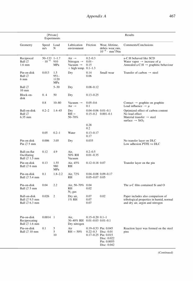
fPrivategExperiments
Results
Geometry Speedm/s
LoadN
Lubricationenvironment
Friction Wear, lifetime,debris wear rate,10�6 $ mm3/Nm
Comments/Conclusions
ReciprocalBall B
1.6 mm
50–133$ 10�6
1–1.7910MPa
Air /Nitrogen /Vacuum /þ high temp.
0.2–0.30.01–0.150.1–1.3
a-C:H behaved like SCDWater vapor / increase of mAnnealed a-C:H / graphitic behaviour
Pin-on-diskBall B
6 mm
0.013 1.5951–1120MPa
Dry 0.140.06
Small wear Transfer of carbon / steel
Ball B
10 mm5–30 Dry 0.08–0.12
Block-on-disk
0. 4 50 Dry 0.13–0.25
0.8 10–80 Vacuum /Air /
0.05–0.60.1
Contact / graphite on graphiteLoad influence / m
Ball-on-diskBall B
6.35 mm
0.2–2 1.4–45 DryRH ¼50–70%
0.04–0.060.15–0.2
0.01–0.10.001–0.1
Optimized effect of carbon contentNo load effectMaterial transfer / steelsurface / SiO2
0.280.2
0.05 0.2–1 Water 0.13–0.170.17
Pin-on-diskPin B 5 mm
0.006 3.05 Dry 0.035 No transfer layer on DLCLow adhesion PTFE vs DLC
Ball-on-flatOscillatingBall B 1.5 mm
0.12 4.9 Air,50% RHVacuum
0.2–0.50.01–0.35
Pin-on-diskBall B 6 mm
0.13 1.55980MPa
Air, 45%RH
0.12–0.18 0.07 Transfer layer on the pin
Pin-on-diskBall B 5.4 mm
0.1 1.8–2.2 Air, 72%RH
0.04–0.080.05–0.07
0.09–0.170.05
Pin-on-diskBall B 5 mm
0.04 2.2 Air, 50–70%RHN2 gas
0.040.02
The a-C film contained Si and O
Ball-on-diskBall B 9.5 mmBall B 6.3 mm
0.026 2 Dry air,1% RH
0.070.070.07
0.02 Paper includes also comparison oftribological properties in humid, normaland dry air, argon and nitrogen
Pin-on-diskReciprocatingBall B 1.6 mm
0.0014 1 Air,30–40% RHDry nitrogen
0.15–0.200.01–0.03
0.1–10.01–0.1
Pin-on-diskBall B 10 mm
0.1 5510
AirRH ¼ 50%
0.19–0.530.22–0.30.17–0.25
Pin: 0.045Disc: 0.01Pin: 0.015Disc: 0.022Pin: 0.0055Disc: 0.042
Reaction layer was formed on the steelpins
(Continued)
467Appendix A

Tribology data sheet for coatings: Diamond-like coatings (Continued)
fPrivategReference
Coating Counterface
No. Year Authors Film Depositionmethod
Substrate Thicknessmm
Roughn./Hardn. Ra,mm/Hv
Material Roughn./Hardn. Ra,mm/Hv
17. 1992 Miyoshi et al. Low-densityDLCLow-densityDLCHigh-densityDLCHigh-densityDLC
GlowdischargePVD
SiC 0.25–0.28 Diamond /Si3N4
Diamond /Si3N4
18. 1992 Miyake a-C:HDLC withmixed diamondand graphite
PlasmaCVD
StainlesssteelSUS440C
19. 1992 Holidayet al.
a-C:H FAB /RfEBPVD /Rf CVD /
Tool steelASP23
0.5 0.015–0.017/64Rc
St52100
20. 1993 Blanpainet al.
a-C:H Rfplasma /Arc ionplating /Laserablation /
StainlesssteelCem.carbideSi(100)
211
0.17/5 GPa0.25/13 GPa0.06/25 GPa
Corundum
21. 19961999c
Ronkainenet al.Ronkainenet al.
a-C:H Rf plasma StainlesssteelAISI 440B
0.5–1 0.03/620 Steel /Alumina /
0.020.04
22. 1998 Ronkainenet al.
a-C /a-C:H /a-C:H(Ti) /
Rf plasmaPulsed vacarc Rf plasma
StainlesssteelAISI 440B
0.50.50.5
0.03/620 Steel 0.02
23. 1998 Miyoshi DLC Ion beam rf Silicon 0.52–0.66 CVDdiamond
24. 2000 Erdemir et al. DLC PlasmaenhancedCVD
Steel /Sapphire /
1 0.05/8 GPamirror/35GPa
DLC onsteelDLC onsapphire
0.05/8 GPamirror/35 GPa
25. 2000 Jiang et al. DLC CFUBMF-PACVD
M42 toolsteel
1.3 0.08 /0.93 /1.15 /
Tungstencarbide
468 Coatings Tribology

Table Continued
fPrivategExperiments
Results
Geometry Speedm/s
LoadN
Lubricationenvironment
Friction Wear, lifetime,debris wear rate,10�6 $ mm3/Nm
Comments/Conclusions
Ball-on-flatReciprocatingBall B
1.3–1.6 mm
0.0014 1 Air,40% RH
0.070.170.050.19
83020.5
DLC more sensitive to moisture thanDC and natural diamond
Ball-on-flatReciprocatingBall B 6.35 mm
0.120 4.9 AirVacuumAirVacuum
0.22–0.50.01–0.30.1–0.30.3–0.4
Low friction due to the formation oforiented hydrocarbons on the ballsurface
Pin-on-diskBall B 10 mm
0.1 AirRH ¼ 50%
0.07–0.110.18–0.450.38–0.48
Ball-on-diskReciprocatingBall B 10 mm
0.0016 1 Air, 23�CRH ¼70–80%
0.1–0.150.05–0.10.05–0.08
0.160.0710.18
Ball-on-diskBall B 10 mm
0.02–3.0
5–40/0.78–1.56 GPa5–40/0.92–1.84 GPa
AirRH ¼ 50%
0.08–0.430.02–0.14
Disc: 0.05–0.18Steel pin:0.002–0.011Disc: 0.04–0.16AlO pin:0.0001–0.00035
Transfer layer formed on pin surface athigh load and high speed
Ball-on-diskReciprocatingBall B 10 mm
0.004 10/0.98 GPa
AirRH ¼ 50%
0.150.220.1
Pin: 1 and disc:smoothingPin: 0.06 anddisc: 0.14Pin: 0.03 anddisc: 0.02
Results from oil with and withoutadditives and water lubrication alsoreported
Ball-on-flatBall B 1.6 mm
0.031–0.107
0.49/2GPa
Air /Nitrogen /Vacuum /Water /
0.030.0250.060.01
0.80.621
Ball-on-flat,Ball B 9.5/St et 6.4/Sa mm
0.2–0.5 10/1 GPaand2.2 GPa
Dry nitrogenandargon
0.0030.001
0.0005–0.010.0003
Ball-on-flatBall B 6.3 mm
0.05 20and 40
Dry airRH ¼ 7%
0.1–0.30.15–0.551–3.5
No influence of normal load. Wearincreases with surface roughness
(Continued)
469Appendix A

Tribology data sheet for coatings: Diamond-like coatings (Continued)
fPrivategReference
Coating Counterface
No. Year Authors Film Depositionmethod
Substrate Thicknessmm
Roughn./Hardn. Ra,mm/Hv
Material Roughn./Hardn. Ra,mm/Hv
26. 2003 Svahn et al. a-C:Wa-C:Cr
Magnetronsputtering
Ballbearingsteel100Cr6
23.5
0.007–0.39/10/W and 7/Cr GPa
Steel(100Cr6)
27. 2003b Zhang et al. DLC Dc plasmaCVD
Silicon 1 Stainlesssteel 440C
28. 2004 Field et al. DLC Magnetronsputtering
M42 toolsteel
/12–18 GPa WC–6%Co
29. 2005 Konca et al. a-C Magnetronsputtering
M42 toolsteel
2.0–2.3 0.034/9.5GPa
319 Alalloy(Al–7%Si)
30. 2005a Klaffke et al. a-C:H(15% H)
RFPA-CVD
Steel SteelCeramic
/180–850/1200–2700
470 Coatings Tribology

Table Continued
fPrivategExperiments
Results
Geometry Speedm/s
LoadN
Lubricationenvironment
Friction Wear, lifetime,debris wear rate,10�6 $ mm3/Nm
Comments/Conclusions
Ball-on-flatBall B 9 mm
0.07 4/0.8 GPa
AirRH ¼30–40%
0.1–0.30.15–0.34
0.2–0.40.18–1.2
Friction and wear increased withsurface roughness
Ball-on-flatBall B 4.76 mm
0.025 1–3/1.2 –1.8 GPa
Air RH ¼20% /RH ¼90% /
0.05–0.22
0.12–0.17
0.022–0.023
0.014–0.018
Formation of transfer layer was shownto control friction. No influence ofspeed on wear
Ball-on-flatBall B 5 mm
0.025 20/1 GPa100/3.5 GPa
Air 0.070.02
0.0250.01
Results from water lubrication alsoreported
Ball-on-flatBall B 4 mm
0.04–0.15
4.9 AirRH ¼ 52%Vacuum0.01 Pa
0.160.52
1.25 $ 10�4
mm3/m4.05 $ 10�4
mm3/m
Very low friction coefficient of 0.006–0.02 was observed in vacuum when firstrun tribopair in ambient air. Presence ofwater vapour essential for low wear
Ball-on-flatReciprocatingBall B 10 mm
0.0820 Hzwith200 mmstroke
10 AirRH ¼ 2%RH ¼ 50%RH ¼ 100%AirRH ¼ 2%RH ¼ 50%RH ¼ 100%
0.06–0.160.07–0.140.05–0.12
0.02–0.040.04–0.140.03–0.09
0.1–0.20.02–0.050.02–0.03
0.09–0.30.1–0.50.05–0.03
471Appendix A

This page intentionally left blank

APPENDIX B

a b
c d
Fig. 3.39. Topographical stress field maps showing first principal stresses on the top of the coating and atthe symmetry plane intersection of a high-speed steel sample coated with a 2 mm thick TiN coating andloaded by a sliding spherical diamond stylus. Sliding direction is from left to right, the sliding stylus isinvisible in the figure and the contact zone is indicated by the white curve. The values on the colour scaleare given in MPa. Stress fields shown are at (a) 5 N pre-load and 0.5 mm indentation depth without sliding,(b) 5.3 N load and 0.06 mm sliding, (c) 10 N load and 1.2 mm sliding and (d) 20 N load and 3.3 mmsliding.
474 Coatings Tribology

Fig. 3.102. Molecular dynamic simulation showing on an atomic level the interactions in a contact witha diamond surface sliding on a DLC coated diamond substrate. The diamond substrate is in blue, theDLC coating in yellow, the diamond contersurface in grey, hydrogen atoms in green and unsaturatedsp-hybridized atoms in the DLC film in red (from Gao et al., 2003, with permission).
475Appendix B

Fig. 4.63. A hydrogen-terminated (H) diamond counterface in sliding contact with an amorphous carbonlayer (DLC) attached to a diamond substrate. Sliding-induced chemical reactions have occurred betweensp-hybridized film atoms and the counterface (from Gao et al., 2003 with permission).
476 Coatings Tribology

REFERENCES
Abebe, M., Appl, F.C., Theoretical analysis of the basic mechanics of abrasive processes, Part I: Generalmodel. Wear, 126 (1988a) 251–266.
Abebe, M., Appl, F.C., Theoretical analysis of the basic mechanics of abrasive processes, Part II: Model ofthe ploughing process. Wear, 126 (1988b) 267–283.
Abel, P.B., Ferrante, J., Surface physics in tribology. In: Modern Tribology Handbook. Bhushan, B. (ed.),Vol. 1, CRC Press, New York, 2001, 5–47.
Abreu, C.S., Oliveira, F.J., Belmonte, M., Fernandes, A.J.S., Silva, R.F., Gomes, J.R., Grain size effect onself-mated CVD diamond dry tribosystem. Wear, 259 (2005) 771–778.
Achanta, S., Drees, D., Celis, J.P., Friction and nanowear of hard coatings in reciprocating sliding atmilli-Newton loads. Wear, 259 (2005) 719–729.
Adachi, K., Hutchings, I.M., Wear-mode mapping for the micro-scale abrasion test. Wear, 255 (2003)23–29.
Adams, F., Van Vaeck, L., Barrett, R., Advanced analytical techniques: platform for nano materialsscience. Spectrochimia Acta Part B – Atom. Spectrosc., 60 (2005) 1, 13–26.
Adams, M.J., Briscoe, B.J., Cartner, A.L., Tweedale, P.J., Assessing the durability of organic coatings. In:Mechanics of Coatings. Dowson, D. et al. (eds), Tribology series, 17, Elsevier, Amsterdam, 1990,139–147.
Agrawal, D.C., Ras, R., Measurement of the ultimate shear strength of a metal–ceramic interface. ActaMetall., 37 (1984) 4, 1265–1270.
Ahmed, S.I.U., Bregliozzi, G., Haefke, H., Microfrictional properties of diamond-like carbon films slidingagainst silicon, sapphire and steel. Wear, 254 (2003) 1076–1083.
Ahn, H.S., A thermo-mechanical stress criterion for failure of surface-coated materials in concentratedsliding contacts. Tribology Int., 26 (1993) 1, 3–10.
Ahn, H.S., Roylance, B.J., Stress behaviour of surface-coated materials in concentrated sliding contact.Surf. Coat. Technol., 41 (1990) 1–15.
Ahn, H.S., Roylance, B.J., Thermal behaviour of surface-coated materials in concentrated sliding contacts.Tribology Int., 25 (1992) 4, 227–236.
Ahlroos, T., Effect of lubricant on the wear of prosthetic joint materials. Acta Polytechnica Scandinavica,Mech. Eng. Series No., 153, 2001, 26 pp.
Ai, X., Moyer, C.A., Rolling element bearings. In: Modern Tribology Handbook. Bhushan, B. (ed.), CRCPress, New York, 2001, 1041–1093.
Aindow, A.M., Dewhurst, R.J., Palmer, S.B., Laser-based non-destructive testing techniques for ultrasoniccharacterisation of subsurface flaws. In: Proc. Ultraconics International, Brighton, Dec. 1984, London,Butterworths, 1985, 329–335.
Aisenberg, S., Diamond-like carbon films – factors leading to improved biocompatilbility, Gulf andWestern Co., USA, 1977, 87–88
Aisenberg, S., Chabot, R., Ion-beam deposition of thin films of diamond like carbon. J. Appl. Phys., 42(1971) 2953–2958.
Aizawa, T., Mitsuo, A., Yamamoto, S., Sumitomo, T., Muraishi, S., Self-lubricated mechanism via the insitu formed lubricious oxide tribofilm. Wear, 259 (2005) 708–718.
Ajayi, O.O., Erdemir, A., Erck, R.A., Fenske, R.G., Nichols, F.A., The role of soft (metallic) films in thetribological behavior of ceramic materials. Wear, 149 (1991) 221–232.
Ajayi, O.O., Erdemir, A., Fenske, G.R., Nichols, F.A., Sproul, W.D., Graham, M., Rudnik, P.J.,Tribological behavior of oil-lubricated TiN-coated steel. Surf. Coat. Technol., 54/55 (1992) 496–501.
Ajayi, O.O., Kovalchenko, A., Hersberger, J.G., Erdemir, A., Fenske, G.R., Surface damage and wearmechanisms of amorphous carbon coatings under boundary lubrication conditions. Surf. Eng., 19(2003) 6, 447–453.
Ajayi, O.O., Soppet, M.J., Erdemir, A., Fenske, G.R., Shi, B., Liang, H., Assessment of amorphous carboncoating for artificial joints application. Trib. Lubr. Technol. (2005) Oct., 40–48.
477

Akagaki, T., Kato, K., Plastic flow process of surface layers in flow wear under boundary lubricatedconditions. Wear, 117 (1987) 179–196.
Akarca, S.S., Altenhof, W.J., Alps, A.T., Subsurface deformation and damage accumulation inaluminum–silicon alloys subjected to sliding contact. Tribology Int., 40 (2007) 735–747.
Akhmatov, A.S., Molecular physics of boundary friction. Translation from: Molekularnaya fizica gra-nichnogo treniya. Gosudarstvennoe Izdatel’stvo Fizico-Matematicheskoi Literatury. Moscow (1963)Israel Program for Scientific Translations, Jerusalem, 1966, 480 pp.
Aksenov, I.I., Strel’nitskij, V.B., Wear resistance of diamond-like carbon coatings. Surf. Coat. Technol., 47(1991) 252–256.
Alahelisten, A., Mechanical and tribological properties of hot flame deposited diamond coatings. ActaUniversitatis Upsaliensis. Dissertations from Faculty of Science and Technology 85, Uppsala, Sweden,1994, 36 pp.
Alahelisten, A., Olsson, M., Hogmark, S., Mechanical and tribological properties of hot flame depositeddiamond on cemented carbide substrates. Proc. 6th Int. Conf. on Tribology EUROTRIB’93, Budapest,Hungary, 3 (1993) 280–285.
Alliston-Greiner, A.F., Greenwood, J.A., Cameron, A., Thickness measurements and mechanical prop-erties of reaction film formed by zinc dialkydithiophosphate during running. Proc. Inst. Mech. Engrs,C178/87 (1987) 565–572.
Almond, E.A., Aspects of various processes for coating and surface hardening. Vacuum, 34 (1984)835.
Amaro, R.I., Martins, R.C., Sebara, J.O., Renevier, N.M., Teer, D.G., Molybdenum disulphide/titaniumlow friction coating for gears application. Tribology Int., 38 (2005) 423–434.
Amberg, S., Skiktbelaggning med PVD-teknik/Coating deposition with PVD technology (in Swedish).Verkstaderna, 30 (1984) 15, 44–48.
Anders, A. (ed.), Handbook of plasma immersion ion implantation and deposition. John Wiley and Sons,New York, USA, 2000, 736 pp.
Anderson, J.R. (ed.), Chemisorption and Reactions in Metallic Films. Academic Press, London, 1971, 555.Anderson, T.L., Fracture Mechanics. Fundamentals and Applications, 2nd edition. CRC Press LLC,
London, UK, 1995, 688 pp.Andersson, J., Microengineered CVD diamond surfaces, triblogy and applications. Acta Universitatis
Upsaliensis. Dissertations from Faculty of Science and Technology 977, Uppsala, Sweden, 2004, 50 pp.Andersson, J., Erck, R.A., Erdemir, A., Frictional behavior of diamondlike carbon films in vacuum and
under varying water vapor pressure. Surf. Coat. Technol., 163–164 (2003a) 535–540.Andersson, J., Erck, R.A., Erdemir, A., Friction of diamond-like carbon films in different atmospheres.
Wear, 254 (2003b) 1070–1075.Anderssson, P., Holmberg, K., Limitations on the use of ceramics in unlubricated sliding applications due
to transfer layer formation. Wear, 175 (1994) 1, 1–8.Andersson, P., Koskinen, J., Varjus, S., Kolehmainen, J., Tervakangas, S., Lubrication improvements and
friction reduction of DLC-coated sliding surfaces by in-process structuring an post polishing. Tribotest,14 (2008) 97–112.
Andersson, S., Soderberg, A., Bjorklund, S., Friction models for sliding dry, boundary and mixed lubri-cated contacts. Proc. of 11th Nordic Symposium on Tribology – NORDTRIB2004, 1-4.6.2004, Tromso,Norway, 651–665.
Angus, J.C., Koidl, P., Domitz, S., Carbon thin films. In: Plasma Deposited Thin Films. Mart, J., Jansen, F.(eds), CRC, Florida, 1986.
Angus, J.C., Diamond and diamond-like films. Thin Solid Films, 216 (1992) 126–133.Anon, Diamond tooling takes off. Diamond Dep., Sci. Technol., 1 (1990) 2, 4.Anthony, T.R., Angus, J.C., Glass, J.T., Diamond and diamond-like films. An intensive one-day course,
lecture notes, part one. In connection with the 1st European Conf. on Diamond and Diamond-likeCarbon Coatings, 17–19.9.1991, Crans-Montana, Switzerland.
Anttila, A., Ion-beam induced diamond-like carbon coatings. In: Structure–Property Relationships inSurface-modified Ceramics. McHargue, C.J. et al. (eds), Kluwer Academic Publishers, 1989, 455–475.
478 References

Aoki, Y., Ohtake, N., Tribological properties of segment-structured diamond-like carbon films. TribologyInt., 37 (2004) 941–947.
Archard, J.F., Contact and rubbing of flat surfaces. J. Appl. Phys., 24 (1953) 981–988.Archard, J.F., Wear theory and mechanisms. In: Wear Control Handbook. Peterson, M.B., Winer, W. (eds),
ASME, New York, 1980, 35–80.Archer, N.J., Yee, K.K., Chemical vapour deposited tungsten carbide wear-resistant coatings formed at
low temperatures. Wear, 48 (1978) 237–250.Argon, A.S., Mechanical properties of near-surface material in friction and wear. In: Fundamentals of
Tribology. Suh, N.P., Saka, N. (eds), MIT Press, London, 1980, 103–125.Arnell, R.D., The mechanisms of tribology of thin film systems. Surf. Coat. Technol., 43/44 (1990)
674–687.Arnell, R.D., Soliman, F.A., The effect of speed, film thickness and substrate surface roughness on the
friction and wear of soft metal films in ultrahigh vacuum. Thin Solid Films, 53 (1978) 333–341.Ashby, M.F., Materials Selection in Mechanical Design, 2nd edition. Butterworth- Heinemann, Oxford,
UK, 1999, 502 pp.ASM Handbook, Vol. 5, Surface Engineering. ASM International, Materials Park, Ohio, USA, 1994.ASTM, Definition of terms relating to adhesion. D907–70, ASTM, Philadelphia, USA, 1970.ASTM, Standard test method for adhesion strength and mechanical failure modes of ceramic coatings by
quantitative single point scratch testing. Designation: C 1624-05, 2005, 28 pp.Atar, E., Kayali, E.S., Cimenoglu, H., Reciprocating wear behaviour of (Zr,Hf)N coatings. Wear, 257
(2004) 633–639.Atkins, A.G., Liu, J.H., Toughness and the transition between cutting and rubbing in abrasive contacts.
Wear, 262 (2007) 146–159.Aubert, A., Nabot, J.P., Ernoult, J., Renaux, P., Preparation and properties of MoS2 films grown by d.c.
magnetron sputtering. Surf. Coat. Technol., 41 (1990) 127–134.Avallone, E.A., Baumeister, T., Marks’ Standard Handbook of Mechanical Engineers, 9th edition.
McGraw-Hill, New York, 1987.Bachmann, P.K., Gartner, G., Lydtin, H., Plasma assisted chemical vapour deposited processes. MRS
Bulletin, 13 (1988) 52–59.Bachmann, P.K., Messier, R., Emerging technology of diamond thin films. Chem. and Engr. News, May
15, 1989, 24–39.Baek, D.K., Khonsari, M.M., Friction and wear of rubber coating in fretting. Wear, 258 (2005) 898–905.Bahadur, S., Wear research and development. J. of Lubrication Technology, Trans. ASME, 100 (1978)
449–454.Bahadur, S., Friction and wear of polymers and composites. In: Tribology of Mechanical Systems.
Vizintin, J., Kalin, M., Dohda, K., Jahamir, S. (eds), ASME Press, New York, 2004, 239–265.Bair, S., Winer, W.O., A rheological model for elastohydrodynamic contacts based on primary laboratory
data. J. Lubr. Tech., Trans.ASME F, 101 (1979) 258–265.Baker, M.A., Kench, P.J., Joseph, M.C., Tsotsos, C., Leyland, A., Matthews, A., The nanostructure and
mechanical properties of PVD CrCu(N) coatings. Surf. Coat. Technol., 162 (2003) 222–227.Baker, M.A., Kench, P.J., Tsotsos, C., Gibson, P.N., Leyland, A., Matthews, A., Investigation of the
nanostructure and wear property of physical vapor deposited coatings. J. Vac. Sci. Technol., A23/3(2005) 423–433.
Bamberger, E.N., Clark, J.C., Development and application of the rolling contact fatigue test rig. In:Rolling Contact Fatigue Testing of Bearing Steels. Hoo, J.J.C. (ed.), ASTM STP 771, American Societyfor Testing Materials, 1982, 85–106.
Bandorf, R., Luthje, H., Wortmann, T., Staedler, T., Wittorf, R., Influence of substrate material andtopography on the tribological behaviour of submicron coatings. Surf. Coat. Technol., 174–175 (2003)461–464.
Barriga, J., Kalin, M., Van Acker, K., Vercammen, K., Ortega, A., Leiaristi, L., Tribological performanceof titanium doped and pure DLC coatings combined with a synthetic bio-lubricant. Wear, 261 (2006)9–14.
479References
Barros Bouchet de, M.I., Martin, J.M., New trends in boundary lubrication of DLC coatings. In: Tribologyof Diamond-like Carbon Films. Donnet, C., Erdemir, A. (eds), Springer, New York, USA, 2008,591–619.
Barros’Bouchet, M.I., Martin, J.M., Le-Mognet, T., Vacher, B., Boundary lubrication mechanisms ofcarbon coatings by MoDTC and ZDDP additives. Tribology Int., 38 (2005) 257–264.
Bartz, W.J., Xu, J., Wear behavior and failure mechanism of bonded solid lubricants. ASLE Preprint no.86-AM-6F-1, ASLE An. Meeting May 1986, 8 pp.
Bartz, W.J., Holinski, R., Xu, J. A study on the behavior of bonded lubricating films containingmolybdenum disulfide (MoS2), graphite and antimony-thioantimonate (Sb(SbS4). Proc. 3rd Int. Conf.on Solid Lubrication, ASLE SP-14, 1984, 88–97.
Bartz, W.J., Holinski, R., Xu, J., Wear life and friction behavior of bonded solid lubricants. Lubr. Enging,J. ASLE, 42 (1986) 12, 762–769.
Barwell, F.T., Bearing Systems – Principles and Practice, Oxford University Press, Oxford, 1979, 565 pp.Batista, J.C.A., Godoy, C., Matthews, A., Impact testing of duplex and non-duplex (Ti,Al)N and Cr–N
PVD coatings. Surf. Coat. Technol., 163–164 (2003) 353–361.Batista, J.C.A., Joseph, M.C., Godoy, C., Matthews, A., Micro-abrasion wear testing of PVD TiN coatings
on untreated and plasma nitrided AISI H13 steel. Wear, 249 (2002) 971–979.Bayer, R.G. (ed.), Selection and use of wear tests for metals. ASTM STP 615. American Society for
Testing Materials, Philadelphia, 1977.Bayer, R.G. (ed.), Selection and use of wear tests for coatings. ASTM STP 769. American Society for
Testing Materials, Philadelphia, USA, 1982, 179.Bayer, R.G., Shalkey, A.T., Wayson, A.R., Designing for zero wear. Machine Design, 1969, Jan., 142–151Bayer, R.G., Mechanical Wear Prediction and Prevention, Marcel Dekker, New York, 1994, 657 pp.Bec, S., Tonk, A., Georges, J.M., Coy, R.C., Bell, J.C., Roper, G.W., Relationship between mechanical
properties and structures of zinc dithiophosphate anti-wear films. Proc. R. Soc. Lond. A 455 (1999)4181–4203.
Becker, E.P., Trends in tribological materials and engine technology. Tribology Int., 37 (2004) 569–575.Bedford, G.M., Richards, P.J., The fricsurf process – a new coating technology. Proc. Eng. Surface Conf.,
London, May 1986, Inst. of Metals, 5/1–5/2.Beer, P., Rudnicki, J., Ciupinski, L., Djouadi, M.A., Nouveau, C., Modification by composite coatings of
knives made of low alloy steel for wood machining purposes. Surf. Coat. Technol., (2003). 174–175434–439.
Beerschwinger, U., Albrecht, T., Mathieson, D., Reuben, R.L., Yang, S.J., Taghizadeh, M., Wear atmicroscopic scales and light loads for MEMS applications. Wear, 181–183 (1995) 426–435.
Begelinger, A., De Gee, A.W.J., Failure of the film lubrication – the effect of running-in on the loadcarrying capacity of thin film lubricated concentrated contacts. J. Lubr. Technol., Trans. ASME, 103(1981) 203–210.
Belak, J., Boercker, D.B., Stowers, I.F., Simulation of nanometer-scale deformation of metallic andceramic surfaces. MRS Bulletin, 18 (1993) 5, 55–59.
Bell, T., Dong, H., Sun, Y. Realising the potential of duplex surface engineering. Tribology Int., 31/1–3(1998a) 1–3, 127–137.
Bell, T., Mao, K., Sun, Y., Surface engineering design: modeling surface engineering systems forimproved tribological performance. Surf. Coat. Technol., 108–109 (1998b) 360–368.
Bell, T., Sun, Y., The load bearing capacity of plasma nitrided steel under rolling/sliding contact. SurfaceEngng, 6 (1990) 133–139.
Bely, V.A., Sviridenok, A.I., Petrokovets, M.I., Savkin, V.G., Friction and Wear in Polymer-basedMaterials, Pergamon Press, Oxford, 1982, 415 pp.
Bemporad, E., Sebastiani, M., Pecchio, C., De Rossi, S., High thickness Ti/TiN multilayer thin coatingsfor wear resistant applications. Surf. Coat. Technol., 201 (2006) 2155–2165.
Ben Tkaya, M., Zahouani, H., Mezlini, S., Kapsa, P., Zidi, M., Dogui, A., The effect of damage in thenumerical simulation of a scratch test. Wear, 263 (2007) 1533–1539.
Benjamin, P., Weaver, C., Measurement of adhesion of thin film. Proc. R. Soc., A254 (1959) 163–176.
480 References
Benjamin, P., Weaver, C., The adhesion of evaporated metal films on glass. Proc. R. Soc., A261 (1961)516–531.
Benjamin, P., Weaver, C., The adhesion of metals to crystal faces. Proc. R. Soc., A274 (1963) 267–273.Bennett, S., Matthews, A., Valli, J., Perry, A.J., Bull, S.J., Sproul, W.D., Multi-pass scratch testing at
sub-critical loads. 19th Int. Conf. Metallurgical Coatings and Thin Films (ICMCTF 92), San Diego,USA 6-10.4.1992, 6 pp. Submitted to Tribologia – Finnish J. Tribology.
Berger, M., Thick physical vapour deposited TiB2 coatings. Surf. Engng, 18 (2002) 3, 219–223.Berger, M., Larsson, M., Mechanical properties of multilayer PVD Ti/TiB2 coatings. Surf. Engng. 16
(2000) 2, 122–126.Berger, M., Wiklund, U., Eriksson, M., Engqvist, H., Jacobson, S., The multilayer effect in abrasion –
optimising the combination of hard and tough phases. Surf. Coat. Technol., 116–119 (1999)1138–1144.
Berghaus, B., Improvements in and related to the coating of articles by means of thermally vapourizedmaterial. UK Patent specification 510992 (1938).
Bergman, B., Industriell forsoksplanering och robust konstruktion/Industrial experiment and robustdesign. In Swedish, Studentlitteratur, Lund, Sweden, 1992, 328 pp.
Berman, A., Drummond, C., Israelichvili, J., Amonton’s law at the molecular level. Tribology Lett, 4(1998) 95–101.
Bernardo, A.T., Araujo, J.A., Mamiya, E.N., Proposition of a finite element-based approach to computethe size effect in fretting fatigue. Tribology Int., 39 (2006) 1123–1130.
Berthier, Y., Third-body reality – consequences and use of the third-body concept to solve friction andwear problems. In: Wear – Materials, Mechanisms and Practice. Stachowiak, G. (ed.), Tribology inPractice Series, John Wiley, Sons, Chichester, UK, 2005, 291–316.
Berthier, Y., Godet, M., Brendle, M., Velocity accommodation in friction. Tribology Trans., 32 (1989) 4,490–496.
Berthier, Y., Vincent, L., Godet, M., Velocity accommodation in fretting. Wear, 125 (1988) 25–38.Bertrand-Lambotte, P., Loubet, J.L., Verpy, C., Pavan, S., Understanding of automotive clearcoats scratch
resistance. Thin Solid Films, 420–421 (2002) 281–286.Beuth, J.L., Cracking of thin bonded films in residual tension. Int. J. Solids Structures, 29, 13 (1992)
1657–1675.Bhansali, K.J., Kattamis, T.Z., Quality evaluation of coatings by automatic scratch testing. Wear, 14
(1990) 59–71.Bhattacharya, K., James, R.D., A theory of thin films of martensitic materials with applications to
microactuators. J. Mech. Phys. Solids, 47 (1999) 531–576.Bhattacharya, R.S., Evaluation of high energy ion-implanted polycarbonate for eyewear applications. Surf.
Coat. Technol., 103–104 (1998) 151–155.Bhushan, B., Development of a wear test apparatus for screening bearing-flange materials in computer
tape drives. ASLE Transactions, 30 (1987) 2, 187–195.Bhushan, B., Tribological design – information storage and retrieval. Leeds-Lyon Symp. on Tribology,
6–9.9.1988, Leeds, UK, 13 pp.Bhushan, B., Tribology and Mechanics of Magnetic Storage Devices, Springer-Verlag, New York, 1990.Bhushan, B. (ed.), Handbook of Micro/Nanotechnology. CRC Press, London, 1995, 628 pp.Bhushan, B., Tribology and Mechanisms of Magnetic Storage Devices, IEEE Press, Springer, New York,
1996, 1125 pp.Bhushan, B., Contact mechanics of rough surfaces in tribology: multiple asperity contact. Tribology Lett.,
4 (1998a) 1–35.Bhushan, B., (ed.), Tribology issues and opportunities in MEMS. Proc.. of NSF/AFOSR/ ASME Work-
shop on Tribology Issues and Opportunities, MEMS, 9–11 November 1997, Columbus, USA, KluverAcademic Publishers, London, 1998b.
Bhushan, B., Chemical, mechanical and tribological characterization of ultra-thin and hard amorphouscarbon coatings as thin as 3.5 nm: recent developments. Diamond and Related Materials, 8 (1999a)1985–2015.
481References

Bhushan, B., Nanotribology of ultrathin and hard amorphous carbon films. In: Tribology of Diamond-likeCarbon Films. Donnet, C., Erdemir, A. (eds), Springer, New York, USA, 2008, 510–570.
Bhushan, B., Principles and Applications in Tribology. John Wiley, Sons, New York, 1999b, 1020 pp.Bhushan, B. (ed.), Fundamentals of tribology and bridging the gap between the macro- and micro/
nanoscales. NATO Science Series, II. Mathematics, Physics and Chemistry, Vol. 10, Kluver AcademicPublishers, Boston, 2001a, 963 pp.
Bhushan, B., Macro- and microtribology of magnetic storage devices. In: Modern Tribology Handbook.Bhushan, B. (ed.), CRC Press, New York, 2001b, 1413–1513.
Bhushan, B., Macro- and microtribology of MEMS materials. In: Modern Tribology Handbook. Bhushan,B. (ed.), CRC Press, New York, 2001c, 1515–1548.
Bhushan, B., Tribology on the macroscale of microelectromechanical system materials: a review. Proc.Instn. Mech. Engrs Part J 215 (2001d) 1–18.
Bhushan, B., Surface roughness analysis and measurement techniques. In: Modern Tribology Handbook.Bhushan, B. (ed.), CRC Press, New York, 2001e, 49–119.
Bhushan, B., Nanotribology and nanomechanisms. Wear, 259 (2005) 1507–1531.Bhushan, B., Gupta, B.K., Handbook of Tribology – Materials, Coatings and Surface Treatments,
McGraw-Hill Inc., New York, 1991, 1168 pp.Biederman, H., The properties of films preparation by the sputtering of PTFE and plasma polymerization
of some freons. Vacuum, 31 (1981) 7, 285–289.Billgren, P., The use of nitride and carbide coatings on high speed steel tools. Speedsteel Technical Report
ZSD 22/84 (1984).Bin-Sudin, M., Leyland, A., James, A.S., Matthews, A., Housden, J., Garside, B.L., Substrate surface
finish effects in duplex coatings of PAPVD TiN and CrN with electroless nickel–phosphorus interlayers.Surf. Coat. Technol., 81 (1996) 215–224.
Birkholz, M., Fewsrer, P.F., Gentzel, C., Thin Film Analysis by X-ray Scattering, Wiley, New York, USA,2006.
Bishop, H.E., Auger electron spectroscopy. In: Methods of Surface Analysis. Walls, J.M. (ed.), CambridgeUniversity Press, 1989, 87–126, 36 pp.
Bjork, T., Berger, M., Westergard, R., Hogmark, S., Bergstrom, J., New physical vapour depositioncoatings applied to extrusion dies. Surf. Coat. Technol., 146–147 (2001) 33–41.
Blanchet, T.A., Kennedy, F.E., Sliding wear mechanism of polytetrafluoroethylene (PTFE) and PTFEcomposites. Wear, 153 (1992) 229–243.
Blanpain, B., Celis, J.P., Roos, J.R., A comparative study of the fretting wear of hard carbon coatings. ThinSolid Films, 223 (1993) 65–71.
Blanpain, B., Franck, M., Mohrbacher, E., Vancoille, J.P., Celis, J.P., Roos, J.R., Micro-Raman spec-troscopy for the characterization of wear induced surface modifications on hard coatings. 19thLeeds–Lyon Symp. on Tribology, Thin films in tribology, Leeds 8–11.9.1992, 9 pp.
Blau, P.J., Friction and Wear Transitions of Materials – Break-in, Run-in, Wear-in, Noyes Publications,Park Ridge, New Jersey, USA, 1989, 476 pp.
Blau, P., Simulative friction and wear testing. In: Modern Tribology Handbook. Bhushan, B. (ed.), CRCPress, New York, 2001, 511–522.
Blau, P., Tribology web page.https://www.ms.ornl.gov/researchgroups/SPM/methods/Tribology/Tribology.htm. 25.6, 2008.
Blau, P.J., Yust, C.S., Clausing, R.E., Morphological aspects of the friction of hot-filament-grown diamondthin films. In: Mechanics of Coatings. Dowson, D. et al. (eds), Tribology Series 17, Elsevier,Amsterdam, 1990, 399–407.
Blomberg, A., Friction and wear of ceramics. PhD thesis, Uppsala University, Material Science Division,1993, 47 pp.
Blomberg, A., Erickson, L., Lu, J., Hogmark, S., Olsson, M. Improved wear resistance of ceramics throughthe use of coatings. Surf. Coat. Technol., in press, 1993, 16 pp.
Blug, B., Konrath, G., Hollstein, T., Low friction coasting – a new design element for engineers. Proc. 2ndWorld Tribiology Congress, 3–7.9.2001, Vienna, Austria, Austrian Tribiology Society, 281–284.
482 References
Boelens, S., Veltrop, H., Hard coatings of TiN, (TiHf)N and (TiNb)N deposited by random and steered arcevaporation. Surf. Coat. Technol., 33 (1987) 63–71.
Booser, E.R., Tribology Data Handbook, CRC press, New York, USA, 1997, 1099 pp.Boothroyd, G., Temperatures in orthogonal metal cutting. Proc. Inst. Mech. Engrs, 177 (1963) 29,
789–810.Borland, D.W., Residual stress measurement – methods, limitations and significance. In: Quality Control
and Assurance in Advanced Surface Engineering. Strafford, K.N., Subramanian, C. (eds), The Instituteof Materials, The University Press, Cambridge, UK, 1997, 113–125.
Borodich, F.M., Chung, Y.W., Keer, L.M., Environmental and surface chemical effects on tribologicalproperties of carbon-based coatings. In: Tribology of Diamond-like Carbon Films. Fundamentals andApplications. Donnet, C., Erdemir, A. (eds), Springer, New York, USA, 2008, 282–290.
Borodich, F.M., Harris, S.J., Keer, L.M., Cooper, C.V., Wear and abrasiveness of hard carbon-containingcoatings under variation of the load. Surf. Coat. Technol., 179 (2004) 78–82.
Borodich, F.M., Keer, L.M., Harris, S.J., Self-similarity in abrasiveness of hard carbon-containing coat-ings. J. Tribology, Trans. ASME, 125 (2003) 1–7.
Borruto, A., Crivellone, G., Marani, F., Influence of wettability on friction and wear tests. Wear, 222(1998) 57–65.
Bose, K., Wood, R.J.K., Optimum test conditions for attaining uniform rolling abrasion in ball crateringtests on hard coatings. Wear, 258 (2005) 322–332.
Bouslykhane, K., Moine, P., Villain, J.-P., Grilhe, J., Mechanical properties and wear resistance ofion-beam-assisted sputter-deposited NiTi(N) coatings. Surf. Coat. Technol., 49 (1991) 457–461.
Bouzakis, K.D., Hadjiyiannis, S., Skordaris, G., Anastopoulos, J., Mirisidis, I., Michailidis, N.,Efstathiou, K., Knotek, O., Erkens, G., Cremer, R., Rambadt, S., Wirth, I., The influence of the coatingthickness on its strength properties and on the milling performance of PVD coated inserts. Surf. Coat.Technol., 174–175 (2003) 393–401.
Boving, H.J., Hintermann, H.E., Properties and performance of chemical-vapour-deposited TiC coatedball-bearing components. Thin Solid Films, 153 (1987) 253–266.
Boving, H., Hintermann, H.E., Begelinger, A., De Gee, A.W.J., Load-carrying capacity of lubricated steelpoint contacts coated by chemical vapour deposition. Wear, 88 (1983) 13–22.
Boving, H., Hintermann, H., Hanni, W., Ball bearing with CVD–TiC coated components. Proc. 3rdEuropean Space Mechanisms and Tribology Symposium, Madrid, Spain, 30.9–2.10.1987, 155–159.
Bowden, F.P., Tabor, D., Friction and Lubrication of Solids. Part I. Oxford, Oxford UP, Oxford, UK, 1950,321 pp.
Bowden, F.P., Tabor, D., The friction and Lubrication of Solids. Part II. Oxford, Oxford UP, UK, 1964,515 pp.
Bower, A.F., Fleck, N.A., Brittle fracture under a sliding line contact. J. Mech. Phys. Solids, 42 (1994) 9,1375–1396.
Box, G.E.P., Hunter, W.G., Hunter, J.S., Statistics for Experimenters, John Wiley, New York, USA, 1978,653 pp.
Boxman, R.L., Haber, D., Martin, P.J., Handbook of Vacuum Arc Science and Technology. WilliamAndrew, New York, USA, 1996, 773 pp.
Boxman, R.L., Zhitomirsky, V.N., Grimberg, I., Rapoport, L., Goldsmith, S., Beiss, B.Z., Structure andhardness of vacuum arc deposited multi-component nitride coatings of Ti, Zr and Nb. Surf. Coat.Technol., 125 (2000) 257–262.
Bragallini, G.M., Cavatorta, M.P., Sainsot, P., Coated contacts: a strain approach. Tribology Int., 36 (2003)935–941.
Bray, R.C., Film adhesion studies with the acoustic microscope. Thin Solid Films, 74 (1980) 15,295–302.
Breton, E., Dubourg, M.C., Adhesion for coatings. 18th Leeds–Lyon Symp. on Tribology, 3–6.9.1991a,Lyon, France, Elsevier Tribology Series No. 21, Amsterdam, Netherlands, 41–47.
Breton, E., Dubourg, M.C., Behaviour of cracked coating submitted to Hertzian moving contact. 18thLeeds–Lyon Symp. on Tribology, 3–6.9.1991b, Lyon, France, 8 pp.
483References
Brewe, D.E., Slider bearings. In: Modern Tribology Handbook. Bhushan, B. (ed.), CRC Press, New York,2001, 969–1039.
Briggs, D., Grant, J.T. (eds), Surface Analysis by Auger and X-ray Photoelectron Spectroscopy. Wiley,New York, USA, 2003.
Briscoe, B.J., Pooley, C.M., Tabor, D., Friction and transfer of some polymers in unlubricated sliding. In:Advances in Polymer Friction and Wear – Polymer Science and Technology. Lee, H. (ed.), PlenumPress, New York, 1974, 191–204.
Briscoe, B.J., Tabor, D., The sliding wear of polymers: a brief review. In: Fundamentals of Tribology.Suh, N.P., Saka, N. (eds), The MIT Press, London, 1980, 733–758.
Briscoe, B.J., Sinha, S.K., Wear of polymers. Proc. Instn Mech. Engrs, Part J, 216 (2002) 401–413.Briscoe, B.J., Sinha, S.K., Tribology of polymeric solids and their composites. In: Wear – Materials,
Mechanics and Practice. Stachowiak, G.W. (ed.), John Wiley, Sons, Chichester, UK, 2005, 223–267.Broek, D., Elementary Engineering Fracture Mechanics. Kluwer Academic Publishers, Dordrecht, 1997.Bromark, M., Larsson, M., Hedenqvist, P., Olsson, M., Hogmark, S., Influence of substrate and surface
topography on the critical surface force in scratch adhesion testing of TiN-coated steels. Surf. Coat.Technol., 52 (1992) 195–203.
Bromark, M., Larsson, M., Hedenquist, P., Olsson, M., Hogmark, S., Bergmann, E., PVD coatings for toolapplications: tribological evaluation. Surf. Engng, 10 (1994) 3, 205–214.
Bromark, M., Wear resistance of PVD coatings for tool applications. PhD thesis at Uppsala University,Sweden, Acta Universitatis Upsaliensis, Faculty of Science and Technology Dissertations Nr 192, 1996,42 pp.
Brookes, C.A., Brookes, E.J., Diamond in perspective: a review of mechanical properties of naturaldiamond. Diamond and Related Materials, 1 (1991) 13–17.
Brossa, F., Lang, E., Plasma spraying – a versatile coating technique. In: Advanced Techniques for SurfaceEngineering. Gissler, W., Jehn, H.A. (eds), Kluwer Academic Publishers, Dordrecht, 1992, 199–234.
Brudnyi, A.I., Karmodonov, A.F., Structure of molybdenum disulphide lubricant film. Wear, 33 (1975)243.
Bruno, M., Bugliosi, S., Chiara, R., The performance of titanium-nitride coated HSS tools. J. Engng Mat.Tech., 110 (1988) 274–277.
Brydson, J.A., Handbook for Plastics Processors, Heinemann Newnes, Oxford, UK, 1990, 208 pp.Buckley, D., The use of analytical surface tools in the fundamental study of wear. Wear, 46 (1978) 19–53.Buckley, D., Surface effects in adhesion, friction, wear, and lubrication. Elsevier, Amsterdam, 1981,
631 pp.Buckley, D., Properties of surfaces. In: CRC Handbook of Lubrication – Theory and Practice of Tribology.
Volume II Theory and Design. Booser, E. (ed.), CRC Press Inc., Boca Raton, Florida, 1984, 17–30.Budinski, K.G., Tool materials. In: Wear Control Handbook. Peterson, M.B., Winer, W. (eds), American
Society of Mechanical Engineers, New York, USA, 1980, 931–986.Bull, S.J., Failure modes in scratch adhesion testing. Surf. Coat. Technol., 50 (1991) 25–32.Bull, S.J., Interfaces and adhesion. In: Advanced Techniques for Surface Engineering. Gissler, W.,
Jehn, H.A. (eds), Kluwer Academic Publishers, Dordrecht, The Netherlands, 1992, 31–68.Bull, S.J., Failure mode maps in the thin film scratch adhesion test. Tribology Int., 30 (1997) 7, 491–498.Bull, S.J., Physical vapour deposition methods for protection against wear. In: Surface Coatings for
Protection against Wear. Mellor, B.G. (ed.), CRC Press, Woodhead Publishing Ltd, Cambridge, UK,2006, 146–183.
Bull, S.J., Berasetegui, E.G., An overview of the potential of quantitative coating adhesion measurementby scratch testing. Tribology Int., 39 (2006) 99–114.
Bull, S.J., Berasetegui, E.G., Page, T.F., Modelling of the indentation response of coatings and surfacetreatments. Wear, 256 (2004) 857–866.
Bull, S.J., Bhat, D.G., Staia, M.H., Properties and performance of commercial TiCN coatings. Part 1:Coating architecture and hardness modeling. Surf. Coat. Technol., 163–164 (2003a) 499–506.
Bull, S.J., Bhat, D.G., Staia, M.H., Properties and performance of commercial TiCN coatings. Part 2:Tribological performance. Surf. Coat. Technol., 163–164 (2003b) 507–514.
484 References
Bull, S.J., Chalker, P.R., Lubricated sliding wear of physically vapour deposited titanium nitride. Surf.Coat. Technol., 50 (1992) 117–126.
Bull, S.J., Rickerby, D.S., Compositional, microstructural and morphological effects on the mechanicaland tribological properties of chromium nitrogen films. Surf. Coat. Technol., 43/44 (1990a) 732–744.
Bull, S.J., Rickerby, D.S., New developments in the modelling of the hardness and scratch adhesion of thinfilms. Surf. Coat. Technol., 42 (1990b) 149–164.
Bull, S.J., Rickerby, D.S., Evaluation of coatings. In: Advanced Surface Coatings – A Handbook ofSurface Engineering. Rickerby, D.S., Matthews, A. (eds), Blackie, London, 1991, 315–342.
Bull, S.J., Rickerby, D.S., Gent, J.T., Quality assurance assessment of thin films. Surf. Engng, 7 (1991) 2,145–153.
Bull, S.J., Rickerby, D.S., Jain, A., The sliding wear of titanium nitride coatings. Surf. Coat. Technol., 41(1990) 269–283.
Bull, S.J., Rickerby, D.S., Matthews, A., Leyland, A., Pace, A.R., Valli, J., The use of scratch adhesiontesting for the determination of interfacial adhesion: the importance of frictional drag. Surf. Coat.Technol., 36 (1988a) 503–517.
Bull, S.J., Rickerby, D.S., Robertson, T., Hendry, A., The abrasive wear resistance of sputter ion platedtitanium nitride coatings. Surf. Coat. Technol., 36 (1988b) 743–754.
Bunshah, R.F., Selection and use of wear tests for coatings. In: Selection and Use of Wear Tests forCoatings. Bayer, R.G. (ed.), ASTM STP 796, American Society for Testing Materials, 1982, 3–15.
Bunshah, R.F. (ed.), Handbook of Deposition Technologies for Films and Coatings. Noyes Publications,New Jersey, USA, 1994, 861 pp.
Bunshah, R.F., Nimmagada, R., Doerr, H.J., Movchan, B.A., Grechanuk, N.I., Dabizha, E.V., Structureand property relationships in microlaminate Ni–Cu and Fe–Cu condensates. Thin Solid Films, 72 (1980)261–275.
Bunshah, R.F., Raghuram, A.C., Activated reactive evaporation process for high rate deposition ofcompounds. J. Vac. Sci. Technol., 9 (1972) 1385–1388.
Burnett, P.J., Page, T.F., Surface softening in silicon by ion implantation. J. Mat. Sci., 19 (1984) 854–860.Burnett, P.J., Rickerby, D.S., The mechanical properties of wear-resistant coatings I: Modelling of
hardness behaviour. Thin Solid Films, 148 (1987a) 41–50.Burnett, P.J., Rickerby, D.S., The relationship between hardness and scratch adhesion. Thin Solid Films,
154 (1987b) 403–416.Burnett, P.J., Rickerby, D.S., The erosion behaviour of TiN coatings on steels. J. Mat. Sci., 23 (1988)
2429–2443.Byeli, A.V., Minevich, A.A., Stepanenko, A.V., Gick, L.A., Kholodilov, O.V., Wear resistance and
structure of (Ti,Al)N coatings. J. Phys. D: Appl. Phys., 25 (1992) A292–A296.Cai, S., Bhushan, B., Three-dimensional sliding contact analysis of multilayered solids with rough sur-
faces. Trans. ASME, J. Tribology, 129 (2007) 40–59.Calonius, O., Tribology of prosthetic joints – validation of wear simulation methods. Acta Polytechnica
Scandinavica, Mech. Eng. Series No, 159, 2002, 62 pp.Cameron, A., The Principles of Lubrication, Longmans, London, 1966, 519 pp.Cameron, A., The role of surface chemistry in lubrication and scuffing. Trans. ASLE, 23 (1980) 4,
388–392.Cammarata, R.C., Stresses in thin films. In: Surface Modification and Mechanisms – Friction, Stress,
and Reaction Engineering. Totten, G.E., Liang, H. (eds), Marcel Dekker, Basel, Switzerland, 2004, 17–29.Campbell, D.S., The deposition of thin films by chemical methods. In: Handbook of Thin Film Tech-
nology. Maissel, L.I., Glang, R. (eds), McGraw-Hill, New York, 1970, 5.1–5.24.Canter, N., How does ZDDP function? Tribology Lubr. Technol., June (2005) 20–26.Cantley, R.E., Predicting the effects of lubricant chemistry on bearing fatigue life. ASLE Trans., 26 (1983)
1, 80–86.Carlsson, J.-O., Thermally activated chemical vapour deposition. In: Advanced Surface Coatings:
A Handbook in Surface Engineering. Rickerby, D.S., Matthews, A. (eds), Blackie, Glasgow, UK, 1991,162–193.
485References

Carnes, K., Hard-driving lubrication. Tribology Lubr. Technol., (2004) Nov., 31–38.Caron, I., Gras, R., Ganne, T., De Monicault, J.M., Coatings on Ti6Al4V as palliatives for fretting fatigue
in cryogenic environment. Tribology Int.l, 39 (2006) 1045–1051.Cartier, M. (ed.), Handbook of Surface Treatments and Coatings. Tribology in Practice Series.
Professional Engineering Publishing, London, 2003, 412 pp.Carvalho, N.J.M., Low friction and wear resistant coatings: microstructure and mechanical properties.
PhD thesis, Groningen University, Netherlands, 2001, 142 pp.Casey, M., Wilks, J., The friction of diamond sliding on polished cube faces of diamond. J. Phys. D: Appl.
Phys., 6 (1973) 1772–1781.Cavaleiro, A., De Hosson, J.T.M. (eds), Nanostructured Coatings. Springer, New York, 2006, 648 pp.Cavdar, B., Ludema, K.C., Dynamics of dual film formation in boundary lubrication of steels. Part I.
Functional nature and mechanical properties. Wear, 148 (1991) 305–327.Celis, B., Theoretical analysis of dry friction in brittle and ductile materials. Wear, 116 (1987)
287–298.Celis, J.P., Ponthiaux, P., Wenger, F., Tribo-corrosion of materials: interplay between chemical, electro-
chemical, and mechanical reactivity of surfaces. Wear, 261 (2006) 939–946.Celis, J.P., Roos, J.R., De Bonte, M., Developments and applications of electroless coatings. In: Surface
Modification Technologies. Sudarshan, T.S., Bhat, D.G. (eds), Pennsylvania, USA, The MetallurgicalSociety, 1988, 215–235.
Chala, A., Chekour, L., Nouveau, C., Saied, C., Aida, M.S., Djouadi, M.A., Study of the duplex treatmenton 32CrMoV13 low alloy steel: application in wood machining. Surf. Coat. Technol., 200 (2005)512–516.
Chalker, P.R., Characterisation of coatings and interfaces. In: Advanced Surface Coatings – A Handbookof Surface Engineering. Rickerby, D.S., Matthews, A. (eds), Blackie, London, 1991, 278–314.
Chambers, K.W., Arneson, M.C., Waggoner, C.A., An on-line ferromagnetic wear debris sensor formachinery condition monitoring and failure detection. Wear, 128 (1988) 325–327.
Chambers, D.L., Taylor, K.A., Wan, C.T., Emrick, A.J., Sputtering of polymeric composites. Surf. Coat.Technol., 41 (1990) 315–323.
Chandrasekaran, H., Friction in machining – comparison of rake and flank wear-land friction. Wear, 36(1976) 133–145.
Chang, T.P., Cheng, H.S., Sproul, W.D., The influence of coating thickness on lubricated rolling contactfatigue life. Surf. Coat. Technol., 43/44 (1990) 699–708.
Chang, T.P., Cheng, H.S., Chiou, W.A., Sproul, W.D., A comparison of fatigue failure morphologybetween TiN coated and uncoated lubricated rollers. Tribology Trans., 34 (1991) 408–416.
Chang, F.K., Cominou, M., Barber, J.R., Slip between a layer and a substrate caused by a normal forcemoving steadily over the surface. Int. J. Mech. Sci., 25 (1983) 11, 803–809.
Chang, T.P., Graham, M.E., Sproul, W.D., Cheng, H.S., Scuffing behaviour of TiN-coated steel rollersunder rolling and sliding conditions. Surf. Coat. Technol., 54/55 (1992) 490–495.
Chapman, B., Glow Discharge Process, Wiley, New York, 1980, 177–296.Charitidis, C., Gioti, M., Logotheidis, S., Kassavetis, S., Laskarakis, A., Varsano, I., Comparison of the
nanomechanical and nanoscratch performance of antiscratch layers on organic lenses. Surf. Coat.Technol., 180–181 (2004) 357–361.
Chekour, L., Nouveau, C., Chala, A., Djouadi, M.A., Duplex treatment of 32CrMoV13 steel by ionicnitriding and triode sputtering: application to wood machining. Wear, 255 (2003) 1438–1443.
Chen, W.T., Engel, P.A., Impact on contact stress analysis in multilayer media. Int. J. Solids Structures,8 (1972) 1257–1281.
Cheng, C.C., Erdemir, A., Fenske, G.R., Correlation of interface structure with adhesive strength ofion-plated TiN hard coatings. Surf. Coat. Technol., 39/40 (1989) 365–376.
Cheng, H.S., On some aspects of microelastohydrodynamic lubrication. In: Surface Roughness Effects inLubrication, 4th Leeds–Lyon Symp. on Tribology, Lyon, Sept. 1977, MEP, London, 1978, 71–79.
Cheng, H.S., Fundamentals of elastohydrodynamic contact phenomena. In: Fundamentals of Tribology.Suh, N.P., Saka, N. (eds), MIT Press, Cambridge, MA, USA, 1980, 1009–1048.
486 References

Cheng, H.S., Gears. In: Modern Tribology Handbook. Bhushan, B. (ed.), CRC Press, New York, 2001,1095–1129.
Cheng, J., Bull, S.J., Indentation fracture and toughness assessment for thin optical coatings on glass.J. Phys. D: Appl. Phys., 40 (2007) 5401–5417.
Cheng, C.C., Erdemir, A., Fenske, G.R., Correlation of interface structure with adhesive strength ofion-plated TiN hard coatings. Surf. Coat. Technol., 39/40 (1989) 365–376.
Childs, T.H.C., Friction modeling in metal cutting. Wear, 260 (2006) 310–318.Chiu, Y.P., Harnett, M.J., A numerical solution for layered solid contact problems with applications to
bearings. J. Lubrication Technology, Trans. ASME, 105 (1983) 585–590.Cho, C.W., Hong, B., Lee, Y.Z., Wear life evaluation of diamond-like carbon films deposited by micro-
wave plasma-enhanced CVD and RF plasma-enhanced CVD method. Wear, 259 (2005) 789–794.Chollet, L., Perry, A.J., The stress in ion-plated HfN and TiN coatings. Thin Solid Films, 123 (1985)
223–234.Christensen, H., Some aspects of the functional influence of surface roughness in lubrication. Wear, 17
(1971) 149–162.Christensen, H., A theory of mixed lubrication. Proc. Instn. Mech. Engrs 186/41 (1972) 421–430.Christie, A.B., X-ray protection spectroscopy. In: Methods of Surface Analysis. Walls, J.M. (ed.),
Cambridge University Press, 1989, 127–168.Chu, P.K., Chen, J.Y., Wang, L.P., Huang, N., Plasma-surface modification of biomaterials. Materials
Science and Engineering, R 36 (2002) 143–206.Clemens, B.M., Eesley, G.L., Relationship between interfacial strain and the elastic response of multilayer
metal films. Material Research Society, Mat. Res. Soc. Symp. Proc., 130 (1989) 307–314.Coll, B.F., Sathrum, P., Aharonov, R., Peyre, J.P., Benmalek, M., Tribological properties and oxidation
resistance of graded (Ti,Al)N coatings. 19th Int. Conf. Metallurgical Coatings and Thin Films(ICMCTF 92), San Diego, USA, 6-10.4.1992, 20 pp.
Colton, E., Coating ophthalmic lenses. CERAC Inc. Technical Publications, 7 (1997) 4 Oct.–Dec., 5 pp.Conrad, J.R., Radtke, J.K., Dodd, R.A., Worzala, F.J., Tran, N.C., Plasma source ion implantation tech-
nique for surface modification of metals. J. Appl. Phys., 62 (1987) 4591.Constantinescu, V.N., Nica, A., Pascovici, M., Ceptureanu, G., Nedelcu, S., Sliding Bearings. Allerton
Press Inc., New York, (1985) 555 pp.Cookson, J., Automation sharpens sawing’s edge. Metalworking Production, 127 (1983) 12, 72–93.Cooper, J.A., Dewhurst, R.J., Palmer, S.B., Laser generated ultrasound. In: Proc. Ultrasonics Int.,
Butterworths, London, 1985.Corso, S., Adamo, R., The application of ferrography in monitoring motor oils during engine development.
Lubrication Engineering, J. STLE, 45 (1989) 9, 557–564.Cosemans, P., Zhu, X., Celis, J.P., Van Stappen, M., Development of low friction wear-resistant coatings.
Surf. Coat. Technol., 174–175 (2003) 416–420.Cowan, R.S., Winer, W.O., Application of the thermomechanical wear transition model to layered media.
In: Thin Films in Tribology. Dowson, D. et al. (eds), Tribology Series 25, Elsevier, Amsterdam, 1993,631–640.
Cui, F.Z., Li, D.J., A review of investigations on biocompatibility of diamond-like carbon and carbonnitride films. Surf. Coat. Technol., 131 (2000) 481–487.
Cudworth, C.J., Higginson, G.R., Friction of lubricated soft surface layers. Wear, 37 (1976) 299–312.Czichos, H., Tribology – a systems approach to the science and technology of friction, lubrication and
wear. Tribology Series, 1, Elsevier, Amsterdam, 1978, 400 pp.Czichos, H., Becker, S., Lexow, J., Multilaboratory testing: results from the Versailles advanced materials
and standards programme on wear test methods. Wear, 114 (1987) 109–130.Czichos, H., Becker, S., Lexow, J., International multilaboratory sliding wear tests with ceramics and
steels. Wear, 135 (1989) 171–191.Czichos, H., Advanced materials in tribology. Tribologia – Finnish J. of Tribology, 11 (1992) 3, 3–27.Czichos, H., Habig, K., Tribologie handbuch – Reibung und Verschleiss/Tribology Handbook – Friction
and Wear (in German), Vieweg, Wiesbaden, Germany, 1992, 560 pp.
487References

Dag, S., Ciraci, S., Atomic scale study of superlow friction between hydrogenated diamond surfaces. Phys.Rev. B, 70 (2004). 241401(R).
D’agostino, R., Favia, P., Fracassi, F., Lamendola, R., Plasma-enhanced chemical vapour deposition. In:Advanced Techniques for Surface Engineering. Gissler, W., Jehn, H.A. (eds), Kluwer Academic Pub-lishers, Dordrecht, The Netherlands, 1992, 105–133.
Damasceno, J.C., Camargo, S.S., Freire, F.L., Carius, R., Deposition of Si-DLC films with high hardness,low stress and high deposition rates. Surf. Coat. Technol., 133–134 (2000) 247–252.
Dareing, D.W., Traction coefficients for coated bearing races lubricated with Teflon transfer films. Journalof Tribology, Trans. ASME, 113 (1991) 343–348.
Davidson, J.A., Analysis of clinical and laboratory wear factors and the tribological performance oforthopaedic implants. Japanese J. Tribology, 37 (1992) 4, 399–413.
Davis, J.R., Davis, Associates (eds), Surface Engineering for Corrosion and Wear Resistance. ASMInternational and IOM Communications, USA, 2001, 279 pp.
Dayson, C., The friction of very thin solid film lubricants on surfaces of finite roughness. ASLE Trans, 14(1971) 105–115.
De Chiffre, L., Mechanics of metal cutting and cutting fluid action. Int. J. Mach. Tool Des. Res, 17 (1977)225–234.
De Chiffre, L., Function of cutting fluids in machining. Lubr. Engng, J. STLE, 44 (1988a) 6, 514–518.De Chiffre, L., Restricted contact tools and cutting fluids in machining. In: Proc. 6th Int. Colloquium on
Industrial Lubricants – Properties, Applications, Disposal. Bartz, W.J. (ed.), 12–14.1.1988b, Esslingen,Germany, Vol. II, 11.5-1–11.5-8.
De Chiffre, L., Metal cutting – mechanics and applications. Doctoral thesis, Technical University ofDenmark, Inst. of Manufacturing Engineering, Lyngby, Denmark., PI-Publ. Nr 88-08-A, 1990, 102 pp.
De Wit, E., Blanpain, B., Froyen, L., Celis, J.P., The tribological behaviour of TiN-coatings during frettingwear. Wear, 217 (1998) 215–224.
Dearnaley, G., Ion implantation and ion-assisted coating. In: Advanced Surface Coatings: A Handbook inSurface Engineering. Rickerby, D.S., Matthews, A. (eds), Blackie, Glasgow, UK, 1991, 41–65.
Dearnley, P.A., Tribological challenges for plasma surface engineered materials – a personal review. Soc.of Vacuum Coaters. 49th Annual Technical Conf. Proc. (2006) 507–517.
Dearnley, P.A., Aldrich-Smith, G., Corrosion-wear mechanisms of hard coated austenitic 316L stainlesssteels. Wear, 256 (2004) 491–499.
Dedkov, G.V., Experimental and theoretical aspects of the modern nanotribology. Phys.. stat. sol.(a), 179(2000) 3, 3–75.
Dehbi-Alaoui, A., Matthews, A., Franks, J., The optical and mechanical properties of carbon films grownusing a fast atom beam source. Surf. Coat. Technol., 47 (1991) 722–729.
Dehbi-Alaoui, A. Olliver, A., Matthews, A., Evaluation of diamond-like carbon films on PET. Le Vide, lesCouches Minces, Supplement au No. 261, March–April, 1992, 221–226.
DellaCorte, C., Pepper, S.V., Honecy, F.S., Tribological properties of Ag/Ti films on Al2O3 ceramicsubstrates. Surf. Coat. Technol., 52 (1992) 31–37.
Deng, K., Ko, W.H., Application of diamond-like carbon film for microdynamic devices. IEEE,0-7803-0456-X/92$3.00, 1992, 98–101.
Derjaguin, B.V., Fedoseev, D.B., The synthesis of diamond at low pressure. Scientific American, 233(1975) 102–109.
Descartes, S., Berthier, Y., Competition between mechanical and physico-chemical actions: consequenceson friction. The case of a contact lubricated by a 3rd body stemming from a coating of MoS1.6. In:Proc. of 2nd World Tribology Congress, 3-7.9.2001, Vienna, Austria, Austrian Tribology Society,67-71.
Diao, D., Finite element analysis on local yield map and critical maximum contact pressure for yielding inhard coating with an interlayer under sliding contact. Tribology Int., 32 (1999) 25–32.
Diao, D., Kandori, A., Finite element analysis of the effect of interfacial roughness and adhesionstrength on the local delamination of hard coating under sliding contact. Tribology Int., 39 (2006)849–855.
488 References

Diao, D., Kato, K., Interface yield map of hard coating under sliding contact. Thin Solid Films, 245 (1994)115–121.
Diao, D., Kato, K., Hayashi, K., The local yield map of hard coating under sliding contact. In: Thin Films inTribology. Dowson, D. et al. (eds), Elsevier Science Publishers, Amsterdam, The Netherlands, 1993, 419–427.
Diao, D., Kato, K., Hayashi, K., The maximum tensile stress on a hard coating Ander sliding friction.Tribology Int., 27 (1994a) 4, 267–272.
Diao, D.F., Kato, K., Hokkirogawa, K., Fracture mechanics of ceramic coatings in indentation. Journal ofTribology, Trans. ASME, 116 (1994b) 860–869.
Dick, T., Cailletaud, G., Analytic and FE based estimations of the coefficient of friction of compositesurfaces. Wear, 260 (2006a) 1306–1316.
Dick, T., Cailletaud, G., Fretting modelling with a crystal plasticity model of TiAl4V. Comp. Mat. Sci., 38(2006b) 113–125.
Dick, T., Paulin, C., Cailletaud, G., Fouvry, S., Experimental and numerical analysis of the local andglobal plastic behaviour in fretting wear. Tribology Int., 39 (2006) 1036–1044.
Dickrell, P.L., Sawyer, W.R., Erdemir, A., Fractional coverage model for the adsorption and removal ofgas species and application to superlow friction diamond-like carbon. J. Tribology, Trans. ASME, 126(2004) 615–619.
Didziulis, S.V., Fleischauer, P.D., Soriano, B.L., Gardos, M.N., Chemical and tribological studies of MoS2
films on SiC substrates. Surf. Coat. Technol., 43/44 (1990) 652–662.Dienwiebel, M., Frenken, J.W.M., Superlubricity between graphite surfaces. In: Superlubricity.
Erdemir, A., Martin, J.M. (eds), Elsevier, Amsterdam, Netherlands, 2007, 199–206.Dieter, G.E., Mechanical Metallurgy. Material Science and Engineering Series, McGraw-Hill Book
Company, London, 1986, 751 pp.Dill, J.F., Gardos, M.N., Hinterman, H.E., Boving, H.J., Rolling contact fatigue evaluation of hardcoated
bearing steels. Proc. 3rd ASLE Int. Conf. on Solid Lubr., 5–10.9.1984, Denver, Colorado, USA, 12 pp.Dimigen, H., Hubsch, H., Willich, P., Reichelt, K., Stochiometry and friction properties of sputtered MoS2
layers. Thin Solid Films, 129 (1985) 79–91.Dimigen, H., Klages, C-P., Microstructure and wear behavior of metal-containing diamond-like coatings.
Surf. Coat. Technol., 49 (1991) 543–547.Ding, Y., Jones, R., Khunell, B.T., Elastic–plastic finite element analysis of spall formation in gears. Wear,
197 (1996) 197–205.Djabella, H., Arnell, R.D., Finite element analysis of the contact stresses in an elastic coating on an elastic
substrate. Thin Solid Films, 213 (1992) 205–219.Djabella, H., Arnell, R.D., Finite element analysis of contact stresses in elastic double-layer systems under
normal load. Thin Solid Films, 223 (1993a) 98–108.Djabella, H., Arnell, R.D., Finite element comparative study of elastic stresses in single, double layer and
multilayered coated systems. Thin Solid Films, 235 (1993b) 156–162.Djabella, H., Arnell, R.D., Two-dimensional finite-element analysis of elastic stresses in double-layer
systems under combined surface normal and tangential loads. Thin Solid Films, 226 (1993c) 65–73.Djouadi, M.A., Nouveau, C., Beer, P., Lambertin, M., CrxNy hard coatings deposited with PVD method on
tools for wood machining. Surf. Coat. Technol., 133–134 (2000) 478–483.Doll, G.L., Thin film coatings on rolling bearings for interrupted or reduced lubrication. In: Proc. of
Aerospace Transmission Systems: Who Needs Oil?, 18.9.2003, Solihull, UK, Institution of MechanicalEngineers, 7 pp.
Doll, G.L., Evans, R.D., Ribaudo, C.R., Improving the performance of rolling contact bearings with tri-bological coatings. In: Surface Engineering in Materials Science III. A Agarwal et al. (eds), Warrendale,PA: TMS, 2005, 153–162.
Doll, G.L., Osborn, K.B., Engineering surfaces of precision steel components. Proc. 44th Annual SVCTechnical Conf., Philadelphia, USA, 21–26.4.2001, Albuquerque, NM: SVC, 2001, 78–84.
Doll, G.L., Ribaudo, C.R., Evans, R.D., Engineered surfaces for steel rolling element bearings and gears.Proc. Conf. on Materials Science, Technology 2004, New Orleans, USA, 26–29.9.2004, Warrendale,PA: AIST/TMS, 2004, 367–376.
489References
Dong, H., Bell, T., Designer surfaces for titanium components, Anti-Corrosion Methods and Materials,46/5 (1999) 338–345.
Donley, M.S., Zabinski, J.S., Tribological Coatings in Pulsed Laser Deposition of Thin Films. In:Chrisey, D.B., Hubler, G.K. (eds), Wiley, New York, 1994.
Donnet, C., Tribology of solid lubricant coatings. Condensed Matter News, 4 (1995) 6, 9–24.Donnet, C., Problem-solving methods in tribology with surface-specific techniques. In: Handbook of
Surface and Interface Analysis. Riviere, J.C., Myhra, S. (eds), Marcel Dekker, Basel, Chapter 16, 1998a,697–745.
Donnet, C., Recent progress on the tribology of doped diamond-like and carbon alloy coatings: a review.Surf. Coat. Technol. 100–101 (1998b) 180–186.
Donnet, C., Erdemir, A. (eds), Tribology of diamond-like carbon films – fundamentals and applications.Springer, New York, USA, 2008, 664 pp.
Donnet, C., Fontaine, J., Le Mogne, T., Belin, M., Heau, C., Terrat, J.P., Vaux, F., Pont, G., Diamond-likecarbon-based functionally gradient coatings for space tribology. Surf. Coat. Technol., 120–121 (1999)548–554.
Donnet, C., Le Mogne, T., Martin, J.M., Superlow friction of oxygen-free MoS2 coatings in ultrahighvacuum. Surf. Coat. Technol., 62 (1993) 406–411.
Douglas, A., Doyle, E.D., Jenkins, B.M., Surface modification for gear wear. Int. Tribology Conf., 2–4.12.1987, Melbourne, Australia, (1987) 52–57.
Dowson, D., Elastohydrodynamics. Proc. Instn. Mech. Engrs., /182/Pt3A (1968) 151–167.Dowson, D., History of Tribology, 2nd edition, Professional Engineering Publishing, London, UK, 1998,
768 pp.Dowson, D., Are our joint replacement materials adequate? Proc. Int. Conf. on the Changing Role of
Engineering in Orthopedics, Instn Mech. Engrs, C384/KN1 (1989) 1–5.Dowson, D., Higginson, G.R., New roller-bearing lubrication formula. Engineering, 4 (Aug. 1961)
158–159.Dowson, D., Higginson, G.R., Elasto-hydrodynamic Lubrication – The Fundamentals of Roller and Gear
Lubrication, Pergamon Press, Oxford, 1966, 235 pp.Dowson, D., Jin, Z.M., Metal-on-metal hip joint tribology. Proc. Instn Mech. Engrs, Part H: Engineering in
Medicine, 220 (2006) 107–118.Dowson, D., Neville, A., Bio-tribology and bio-mimetics in the operating environment. Proc. Instn Mech.
Engng, Part J: J. Engng Tribology, 220 (2006) 109–123.Dowson, D., Whomes, T.L., Effect on surface quality upon the traction characteristics of lubricated
cylindrical contacts. Proc. Inst. Mech. Engrs, 182 (1967-68) 292-321.Doyle, E.D., Jewsbury, P., The surface engineering revolution. Materials Australiasia (1986) June, 8–10.Drory, M.D., Thouless, M.D., Evans, A.G., On the decohesion of residually stressed thin films. Acta
Metall., 36 (1988) 8, 2019–2028.Dubourg, M.C., Villechaise, B., Analysis of multiple cracks – Part I: Theory. J. Tribology, Trans. ASME,
114 (1992) 455–461.Dubourg, M.C., Godet, M., Villechaise, B., Analysis of multiple fatigue cracks – Part II: Results.
J. Tribology, Trans. ASME, 114 (1992) 462–468.Dunaevsky, V.V., Friction and wear equations. In: Tribology Data Handbook. Booser, E.R. (ed.), CRC
Press, New York, USA, 1997, 445–454.Dunaevsky, V.V., Jeng, Y-R., Rudzitis, J.A., Surface texture. In: Tribology Data Handbook. Booser, E.R.
(ed.), CRC Press, New York, USA, 1997, 415–434.Dunlop, E., Haupt, J., Schmidt, K., Gissler, W., Hardness and Young’s modulus of diamond-like carbon
films prepared by ion beam methods. In: Proc. 2nd European Conf. on Diamond, Diamond-like andRelated Coatings, Nice, France, 2–6.9.1991, 644–649.
Dunn, M.L., Cunningham, J., Thermo- and electromechanics of thin-film microstructures. Chapter 35. In:Handbook of Nanotechnology. Bhushan, B. (ed.), Springer, Berlin, Germany, 2004, 1039–1081.
Dvorak, S.D., Wahl, K.J., Singer, I.L., Friction behavior of boric acid and annealed boron carbide coatingsstudied by in situ Raman tribometry. Tribology Trans., 45 (2002) 354–362.
490 References

Dwyer-Joyce, R.S., Drinkwater, B.W., Donohoe, C.J., The measurement of lubricant film thickness usingultrasound. Proc. R. Soc. Series A, 459 (2002) 957–976.
Dwyer-Joyce, R.S., Reddyhoff, T., Drinkwater, B., Operating limits for acoustic measurement of rollingbearing oil film thickness. STLE Tribology Trans., 47 (2004) 366–375.
Eason, R. (ed.), Pulsed Laser Deposition of Thin Films: Applications-led Growth of Functional Materials.Wiley, New York, 2006. ISBN: 978-0-471-44709-2.
Eastham, D., Matthews, A., Surface engineering applied to bearings. 1st European Workshop on SurfaceEngineering Technologies and Applications for SMEs, Newcastle-upon-Tyne, UK, 11–15.5.1992,L14–L15. Newcastle Polytechnic, UK.
Ebdon, P.R., Composite coatings with lubricating properties. Trans. Inst. Met. Fin, 65 (1987) 80–82.Eberhardt, A.W., Peri, S., Surface breaking cracks in layered Hertzian contact with friction. STLE Tri-
bology Trans., 38 (1995) 2, 299–304.Echigoya, T., Hyakubu, T., Liu, Z.T., Sasaki, K., Suto, H., Crystal structure and scratch testing of k-Al2O3
on WC–Co substrates with a TiC interlayer. Surf. Coat. Technol., 47 (1994) 111–117.Edwards, C.M., Halling, J., An analysis of the plastic interaction of surface asperities and its relevance to
the value of the coefficient of friction. J. Mech. Engng Sci., 10 (1968) 2, 101–110.El Haddad, M.H., Topper, T.H., Smith, K.N., Prediction of non propagating cracks. Engng Fract. Mech.,
11 (1979) 573–584.El Shabasy, M., Adhesion measurements of thin metallic films: comparison of the direct pull-off and the
scratch methods. Period. Polytech. Electr. Engng, 25 (1981) 283.El-Sherbiny, M., The friction of solid film lubricants: a theoretical approach. 3rd Int. Conf. on Solid
Lubricants, ASLE, Denver, August 1984, 39–43.El-Sherbiney, M.G.D., Halling, J., The Hertzian contact of surfaces covered with metallic films. Wear, 40
(1976) 325–337.El-Sherbiny, M.G., Salem, F.B., Initial wear rates of soft metallic films. Wear, 54 (1979) 391–400.El-Sherbiny, M.G., Salem, F.B., Fatigue wear: a contribution to the wear phenomena of ion-plated thin
metallic films. Wear, 66 (1981) 101–110.El-Sherbiny, M., Salem, F., A wear equation for solid lubricant films. 3rd Int. Conf. on Solid Lubricants,
ASLE, Denver, August 1984, 44–49.El-Sheriny, M., Salem, F., Tribological properties of PVD silver films. ASLE Trans, 29 (1986) 2, 223–228.Elena, M., Guzman, L., Gialanella, S., Production and characterization of boron nitride films obtained by
r.f. magnetron sputtering and reactive ion-beam-assisted deposition. Surf. Coat. Technol., 36 (1988)199–206.
Elsharkwy, A.A., Hamrock, B.J., A numerical solution for dry sliding line contact of multilayered elasticbodies. J. Tribology, Trans. ASME, 115 (1993) 237–245.
Endler, I., Bartsch, K., Leonhardt, A., Scheibe, H.J., Ziegele, H., Fuchs, I., Raatz, C., Preparation and wearbehaviour of woodworking tools coated with superhard layers. Diamond and Related Materials, 8(1999) 834–839.
Engel, L., Klingele, H., An Atlas of Metal Damage. Wolfe Science Books, Carl Hanser Verlag, Munich,Germany, 1981, 271 pp.
Engel, P.A., Hsue, E.Y., Bayer, R.G., Hardness, friction and wear of multiplated electrical contacts. Wear,162–164 (1993) 538–551.
Enke, K., Dimigen, H., Hubsch, H., Frictional properties of diamondlike carbon layers. Appl. Phys. Lett.,36 (1980) 291–292.
Enke, K., Geisler, M., Kieser, J., Munz, W.D., Plasma-activated CVD for the production of protectivelayers in optics, electronics and mechanical engineering. Materials Research Society. Mat. Res. Soc.Proc., 93 (1987) 301–310.
Equey, S., Hauert, R., Rossi, A., Spenser, N.D., Crockett, R., Investigation on the tribofilms formed ondiamond-like carbon coatings in presence of zinc dialkyl dithiophosphate. 34th Leeds–Lyon Sympo-sium on Tribology, Lyon, France, 4–7.9.2007.
Equey, S., Roos, S., Mueller, U., Hauert, R., Spencer, N.D., Crockett, R., Tribofilm formation from ZnDTPon diamond-like carbon. Wear, 264 (2008) 316–321.
491References

Erck, R.A., Erdemir, A., Fenske, G.R., Effect of film adhesion on tribological properties of silver-coatedalumina. Surf. Coat. Technol., 43/44 (1990) 577–587.
Erdemir, A., Rolling-contact fatigue and wear resistance of hard coatings on bearing-steel substrates. Surf.Coat. Technol., 54/55 (1992) 482–489.
Erdemir, A., Solid lubricants and self-lubricating films. In: Modern Tribology Handbook. Bhushan, B. (ed.),CRC Press, New York, 2001a, 787–825.
Erdemir, A., Tribology of diamond, diamond-like carbon and related films. In: Modern TribologyHandbook. Bhushan, B. (ed.), CRC Press, New York, 2001b, 871–908.
Erdemir, A., Friction and wear of diamond and diamond-like carbon films. Proc. Instn Mech. Engrs, PartJ: Engineering Tribology, 216 (2002) 387–400.
Erdemir, A., Design criteria for superlubricity in carbon films and related microstructures. Tribology Int.,37 (2004a) 577–583.
Erdemir, A., Genesis of superlow friction and wear in diamondlike carbon films. Tribology Int., 37(2004b) 1005–1012.
Erdemir, A., Review of engineered tribological interfaces for improved boundary lubrication. TribologyInt., 38 (2005) 249–256.
Erdemir, A., Donnet, C., Tribology of diamond, diamond-like carbon and related films. In: ModernTribology Handbook. Bhushan, B. (ed.), CRC Press, New York, 2001, 871–908.
Erdemir, A., Donnet, C., Tribology of diamond and diamond-like carbon films: an overview. In: Wear –Materials, Mechanisms and Practice. Stachowiak, G.W. (ed.), Tribology in Practice Series, John Wiley& Sons, Chichester, UK, 2005, 191–222.
Erdemir, A., Donnet, C., Tribology of diamond-like carbon films: recent progress and future prospects.J. Phys. D: Appl. Phys., 39 (2006). R331–R327.
Erdemir, A., Eryilmaz, O.L., Superlubricity in diamondlike carbon films. In: Superlubricity. Erdemir, A.,Donnet, C. (eds), Elsevier, Amsterdam, Netherlands, 2007, 253–271.
Erdemir, A., Fenske, G.R., Tribological performance of diamond and diamondlike carbon films at elevatedtemperatures. Tribology Trans., 39 (1996) 4, 787–794.
Erdemir, A., Fontaine, J., Donnet, C., An overview of superlubricity in diamond-like carbon films. In:Tribology of diamond-like carbon films. Donnet, C., Erdemir, A. (eds), Springer, New York, USA,2008, 237–262.
Erdemir, A., Bindal, C., Pagan, J., Wilbur, P., Characterization of transfer layers on steel surfacessliding against diamond-like hydrocarbon films in dry nitrogen. Surf. Coat. Technol., 76–77 (1995)559–563.
Erdemir, A., Busch, D.E., Erck, R.A., Fenske, G.R., Lee, R., Ion-beam-assisted deposition of silver filmson zirconia ceramics for improved tribological behaviour. Lubr. Engng, 47 (1991a) 10, 863–872.
Erdemir, A., Erilmaz, O., Fenske, G., Synthesis of diamond-like carbon films with superlow friction andwear properties. J. Vac. Sci. Technol. A, 18 (2000) 1987–1992.
Erdemir, A., Fenske, G.R., Kazmanli, M.K., Eryilmaz, O.L., Development of superlow friction carbonfilms from hydrocarbon plasmas. Proc. of 2nd World Tribology Congress, 3–7.9.2001, Vienna, Austria,Austrian Tribology Society, 265–289.
Erdemir, A., Fenske, G.R., Erck, R.A., Cheng, C.C., Ion-assisted deposition of silver films on ceramics forfriction and wear control. Lubr. Engng, 46 (1990) 1, 23–30.
Erdemir, A., Halter, M., Fenske, G., Preparation of ultralow-friction surface films on vanadium diboride.Wear, 205 (1997) 236–239.
Erdemir, A., Halter, M., Fenske, G., New oxide-based lubricants for sliding friction and wear applicationsat extreme temperatures. World Ceramic Congress and Forum on New Materials–CIMTEC, 14-19.6.1998, Florence, Italy, 16 pp.
Erdemir, A., Hochman, R.F., Surface metallurgical and tribological characteristics of TiN-coated bearingsteels. Surf. Coat. Technol., 36 (1988) 755–763.
Erdemir, A., Martin, J.M. (eds), Superlubricity. Elsevier, Amsterdam, The Netherlands, 2007, 499 pp.Erdemir, A., Nichols, F.A., Fenske, G.R., Hsieh, J.H., Sliding friction and wear of ceramics with and
without soft metallic films. MRS Bulletin, Oct. (1991b) 49–53.
492 References

Erdemir, A., Switala, M., Wei, R., Wilbur, P., A tribological investigation of the graphite-to-diamond-likebehaviour of amorphous carbon films ion beam deposited on ceramic substrates. Surf. Coat. Technol.,50 (1991c) 17–23.
Erdogan, F., Gupta, G.D., Layered composites with an interface flaw. Int. J. Solids Structures, 7 (1971a)1089–1107.
Erdogan, F., Gupta, G., The stress analysis of multi-layered composites with a flaw. Int. J. SolidsStructures, 7 (1971b) 39–61.
ESDU – A guide to the design and selection of dry rubbing bearings. Engineering Sciences Data Unit,ESDU 87007, 1987, 43 pp.
European Standard, 2000, Advanced technical ceramics – methods of tests for ceramic coatings – Part 3:Determination of adhesion and other mechanical failure modes by scratch test, prEN1071-3:2000:E,CEN Management Centre, Stassartstraat 36, B-1050 Brussels, Belgium, 42 pp.
Evans, C., Cyrogenic diamond turning of stainless steel. Annals of the CIRP, 40 (1991) 1, 571–575.Evans, A.C., Franks, J., Revell, P.J., Diamond-like carbon applied to bioengineering materials. Surf. Coat.
Technol., 47 (1991) 662–667.Evans, D.C., Lancaster, J.K., The wear of polymers. In: Treatise on Materials Science and Technology,
Vol. 13, WEAR. In: Scott, D. (ed.), Academic Press, New York, 1979, 498 pp.Eyre, T.S., Wear characteristics of metals. Tribology Int., Oct. (1976) 203–212.Eyre, T.S., Friction and wear control in industry. Metals and Materials, March 1992, 143.Fancey, K.S., Matthews, A., Ionisation assisted physical vapour deposition of zirconia thermal barrier
coatings. J. Vac. Sci. Technol., A4 (1986). 6 2656–2660.Faraday, M., Experimental relations of a gold (and other metals) to light. Phil. Trans., 147 (1857) 145.Farges, G., Bosch, J.P., Bergmann, E., Friction and adhesive wear behaviour of W–C coatings against steel
and titanium nitride. Wear, 135 (1989) 1–14.Farr, J.P.G., Molybdenum disulphide in lubrication. A review. Wear, 35 (1975) 1–22.Farrow, M., Selecting wear resistance surfaces. Int. Conf. on Metallurgical Coatings (ICMC 86), San
Diego, USA, April 1986.Farrow, M., Gleave, C., Wear resistant coatings. Trans. Inst. Met. Fin., 62 (1984), 7 pp.Fayeulle, S., Ehni, P.D., Singer, I.L., Role of transfer films in wear of MoS2 coatings. In: Mechanics of
Coatings. Dowson, D. et al. (eds), Tribology Series 17, Elsevier, Amsterdam, 1990, 129–138.Fein, R.S., Chemistry in concentrated-conjunction lubrication. In: Interdisciplinary Approach to the
Lubrication of Concentrated Contacts. Ku, P.M. (ed.), NASA SP-237, 1970, 489–527.Felder, E., Bucaille, J., Mechanical analysis of the scratching of metals and polymers with conical in-
denters at moderate and large strains. Tribology Int., 39 (2006) 70–87.Fella, R., Holleck, H., Schulz, H., Preparation and properties of WC–TiC–TiN gradient coatings. Surf.
Coat. Technol., 36 (1988) 257–264.Fellowes, F.C.J., Steen, W.M., Laser surface treatment. In: Advanced Surface Coatings: A Handbook in
Surface Engineering. Rickerby, D.S., Matthews, A. (eds), Blackie, Glasgow, UK, 1991, 244–277.Feng, Z., Field, J.E., Friction of diamond and chemical vapour deposition diamond coatings. Surf. Coat.
Technol., 47 (1991) 631–645.Feng, Z., Field, J.E., The friction and wear of diamond sliding on diamond. J. Phys. D: Appl. Phys., 25
(1992) A33–A37.Fenske, G.R., Kaufherr, N., Lee, R.H., Kramer, B.M., Bunshah, R.F., Sproul, W.D., Characterization of coating
wear phenomena in nitride- and carbide-coated tool inserts. Surf. Coat. Technol., 36 (1988) 791–800.Fernandez-Ramos, C., Sanchez-Lopez, J.C., Justo, A., Rojas, T.C., Papst, I., Hofer, F., Fernandez, A.,
Microstructural characterization of Ti–TiN/CNx gradient-multilayered coatings. Surf. Coat. Technol.,(2004) 180–181, 526–532.
Ferrante, J., Practical applications of surface analytical tools in tribology. Lubr. Engng, J. ASLE, 38 (1982)4, 223–236.
Ferrari, A.C., Non-destructive characterization of carbon films. In: Tribology of Diamond-like CarbonFilms – Fundamentals and Applications. Donnet, C., Erdemir, A. (eds), Springer, New York, USA,2008, 25–82.
493References

Ferrari, A.C., Robertson, J., Interpretation of Raman spectra of disordered and amorphous carbon. Phys.Rev. B, 61 (2000) 20, 14095–14107.
Field, S.K., Jarratt, M., Teer, D.G., Tribological properties of graphite-like and diamond-like carboncoatings. Tribology Int., 37 (2004) 949–956.
Fillot, N., Iordanoff, I., Berthier, Y., Wear modeling and the third body concept. Wear, 262 (2007)949–957.
Finkin, E.F., A theory for the effect of film thickness and normal load in the friction of thin films. J. Lubr.Tech., July (1969) 551–556.
Fischer, K., Oettel, H., Microstructural gradients in thin hard coatings – tailor-made. Surf. Coat. Technol.,91 (1997) 301–312.
Fischer, T.E., Chemical effects in friction. In: Fundamentals of Friction: Macroscopic and MicroscopicProcesses. In: Singer, I.L., Pollock, H.M. (eds), NATO ASI Series, Series E: Applied Sciences, Vol. 220,Kluver Academic Publishers, London, 1992, 299–312.
Fischer-Cripps, A.C., Critical review of analysis and interpretation of nanoindentation test data. Surf.Coat. Technol., 200 (2005) 4153–4165.
Fischer-Cripps, A.C., Karvankova, P., Veprek, S., On the measurement of hardness of super-hard coatings.Surf. Coat. Technol., 200 (2006) 5645–5654.
Fisher, J., Biomedical applications. In: Modern Tribology Handbook. Bhushan, B. (ed.), CRC Press, NewYork, 2001, 1593–1609.
Fisher, J., Hu, X.Q., Stewart, T.D., Williams, S., Tipper, J.L., Ingham, E., Stone, M.H., Davies, C.,Hatto, P., Bolton, J., Riley, M., Hardaker, C., Isaac, G.H., Berry, G., Wear of surface engineeredmetal-on-metal hip prostheses. J. Mat.Sci.: Materials in Medicine, 15 (2004) 225–235.
Fleischauer, P.D., Hilton, M.R., Bauer, R., Effect of microstructure and adhesion on performance ofsputter-deposition MoS2 solid lubricant coatings. In: Mechanics of Coatings. Dowson, D. et al. (eds),Tribology Series 17, Elsevier, Amsterdam, 1990, 121–128.
Fleischauer, P.D., Bauer, R., Chemical and structural effects on the lubrication properties of sputteredMoS2 films. Tribology Trans., 31 (1988) 2, 239–250.
Flewitt, P.E.J., Wild, R., Physical methods for materials characterization, 2nd edition, Taylor and Francis,2003.
Fontaine, J., Belin, M., Le Mogne, T., Grill, A., How to restore superlow friction of DLC: the healingeffect of hydrogen gas. Tribology Int., 37 (2004) 869–877.
Fontaine, J., Donnet, C., Superlow friction of a-C:H films: tribochemical and rheological effects. In:Superlubricity. Erdemir, A., Donnet, C. (eds), Elsevier, Amsterdam, Netherlands, 2007, 273–294.
Fontaine, J., Donnet, C., Erdemir, A., Fundamentals of the tribology of DLC coatings. In: Tribology ofDiamond-like Carbon Films. Donnet, C., Erdemir, A. (eds), Springer, New York, USA, 2008, 139–154.
Fouvry, S., Duo, P., Perruchaut, P., A quantitative approach of Ti–6Al–4V fretting damages: friction, wearand crack nucleation. Wear, 257 (2004a) 916–929.
Fouvry, S., Fridrici, V., Langlade, C., Kapsa, P., Vincent, L., Palliatives in fretting: a dynamical approach.Tribology Int., 39 (2006) 1005–1015.
Fouvry, S., Kapsa, P., An energy description of hard coating wear mechanisms. Surf. Coat. Technol., 138(2001) 141–148.
Fouvry, S., Liskiewicz, T., Kapsa, P., Hannel, S., Sauger, E., An energy description of wear mechanismsand its applications to oscillating sliding contacts. Wear, 255 (2003) 287–298.
Fouvry, S., Wendler, B., Liskiewicz, T., Dudek, M., Kolodziejczyk, L., Fretting wear analysis of TiC/VCmultilayered hard coatings: experiments and modeling approaches. Wear, 257 (2004b) 641–653.
Fowles, P.E., Jackson, A., Murphy, W.R., Lubricant chemistry in rolling contact fatigue – the performanceand mechanism of one antifatigue additive. ASLE Trans., 24 (1981) 1, 107–118.
Franklin, S.E., The wear behaviour of CVD- and PVD-coated tools in metal stamping and plasticsinjection moulding. In: Surface Engineering Practice – Processes, Fundamentals and Applicationsin Corrosion and Wear. Strafford, K.N. et al. (eds), Ellis Horwood, 1990, 60–70.
Franklin, S., The friction and wear characteristics of several wear-resistant surface coatings. Philips CFTTechnology, CTR 545.91.0043 (1991) 24 pp.
494 References

Franklin, S.E., Coating selection and tribological testing for professional equipment applications.Tribotest, 14 (2008) 2, 63–80.
Franklin, S.E., Dijkman, J.A., The implementation of tribological principles in an expert system(‘PRECEPT’) for the selection of metallic materials, surface treatments and coatings in engineeringdesign. Wear, 181 (1995) 3, 1–10.
Franklin, S.E., Beuger, J., A comparison of the tribological behaviour of several wear-resistant coatings.Surf. Coat. Technol., 54/55 (1992) 459–465.
Franks, J., Enke, K., Richardt, A., Diamond-like carbon – properties and applications. Metals andMaterials, Nov. (1990) 695–700.
Freller, H., Haessler, H., Evaluation of existing ion-plating processes for the deposition of multicomponenthard coatings. Surf. Coat. Technol., 36 (1988) 219–232.
Freller, H., Hempel, A., Lilge, J., Lorenz, H.P., Influence of intermediate layers and base materials onadhesion of amorphous carbon and metal–carbon coatings. In: Proc. 2nd European Conf. on Diamond,Diamond-like and Related Coatings, Nice, France, 2–6.9.1991, 563–569.
Frenk, A., Kurz, W., Laser surface treatments: microstructural aspects. In: Advanced Techniques forSurface Engineering. Gissler, W., Jehn, H.A. (eds), Kluwer Academic Publishers, Dordrecht, TheNetherlands, 1992, 235–252.
Fridrici, V., Fouvry, S., Kapsa, P., Fretting wear behaviour of a Cu–Ni–In plasma coating. Surf. Coat.Technol., 163–164 (2003) 429–434.
Friedrich, K., Reinicke, R., Zhang, Z., Wear of polymer composites. Proc. Instn Mech. Engrs, Part J, 216(2002) 415–426.
Fu, Y., Du, H., Zhang, S., Sputtering deposited TiNi films: relationship among processing, stress evolutionand phase transformation behaviours. Surf. Coat. Technol., 167 (2003) 120–128.
Fuchs, E., Oppolser, H., Rehme, H., Particle beam microanalysis, VCH, Weinheim, Germany, 1990, 507 pp.Fujino, T., Iwamoto, K., Tanaka, K., Shima, M., Stress distribution of coated film with a range of coated
film thickness and elastic properties under a single EHL operating condition. Tribology Int., 40 (2007)1638–1648.
Fujisawa, N., Sawain, M.V., James, N.L., Woodard, J.C., Tarrant, R.N., McKenzie, D.R., Carbon coatingof Ti–6Al–4V for reduced wear in combined impact and sliding applications. Tribology Int., 36 (2003)873–882.
Fujisawa, N., McKenzie, D.R., James, N.L., Woodard, J.C., Swain, M.V., Combined influences of me-chanical properties and surface roughness on the tribological properties of amorphous carbon coatings.Wear, 260 (2006) 62–74.
Fujita, H., Spikes, H.A., The formation of zinc dithiophosphate antiwear films. Proc. Instn Mech. Engrs. PtJ: J. Engineering Tribology, 218 (2004) 265–277.
Fukumasu, N.K., Souza, R.M., Numerical analysis of the contact stress development during theindentation of coated systems with substrates with orthotropic properties. Surf. Coat. Technol., 201(2006) 4294–4299.
Furlong, O., Gao, F., Kotvis, P., Tysoe, W.T., Understanding the tribological chemistry of chlorine-,sulphur- and phosphorus-containing additives. Tribology Int., 40 (2007) 699–708.
Furstner, R., Barthlott, W., Neinhuls, C., Walzel, P., Wetting and self-cleaning properties of artificialsuperhydrophobic surfaces. Langmuir, 21 (2005) 956–961.
Fusaro, R.L., Molecular relaxations, molecular orientation and the friction characteristics of polyimidefilms. ASLE Trans., 20 (1977) 1, 1–14.
Fusaro, R.L., Effect of atmosphere and temperature on wear, friction, and transfer of polyimide films.ASLE Trans., 21 (1978) 2, 125–133.
Fusaro, R.L., Mechanisms of lubrication and wear of a bonded solid-lubricant film. ASLE Trans., 24(1981) 2, 191–204.
Fusaro, R.L., Tribological properties of polymer films and solid bodies in a vacuum environment. NASATechnical Memorandum 88966, Cleveland, Ohio, USA, 1987a, 30 pp.
Fusaro, R.L., Sputtered cadmium oxide as a surface pretreatment for graphite solid-lubricant films. Lubr.Engng, 43 (1987b) 10, 790–799.
495References

Gabelli, A., Jacobson, B., Finite element analysis of EHD lubrication of rubber layers. In: Mechanics ofCoatings. Dowson, D. et al. (eds), Tribology Series 17, Elsevier, Amsterdam, 1990, 103–110.
Gachon, Y., Vannes, A.B., Farges, G., Sainte Catherine, M.C., Caron, I., Inglebert, G., Study of sandparticle erosion of magnetron sputtered multilayer coatings. Wear (1999) 233–235, 263–274.
Gahlin R., Bjorkman, H., Rangsten, P., Jacobson, S., Designed abrasive diamond surfaces. Wear 387–394(1999) 233–235.
Galvan, D., Nanocomposite coatings: processing, structure and tribological performance, PhD thesis,Goringen University, Netherlands Institute for Metals Research, Netherlands, 2007, 144 pp.
Gangopadhyay, A., Willermet, P.A., Vassell, W.C., Tamor, M.A., Amorphous hydrogenated carbon filmsfor tribological applications II. Films deposited on aluminium alloys and steel. Tribology Int., 30 (1997)1, 19–33.
Gangopadhyay, A., Mechanical and tribological properties of amorphous carbon films. Tribology Lett., 5(1998) 25–39.
Gao, C., Bredell, L., Kuhlmann-Wilsdorf, D., Makel, D.D., Micromechanics of MoS2 lubrication. Wear,(1993) 162–164, 480–491.
Gao, G.T., Mikulski, P.T., Chateauneuf, G.M., Harrison, J.A., The effects of film structure and surfacehydrogen on the properties of amorphous carbon films. J. Phys. Chem. B, 107 (2003) 40, 11082–11090.
Gao, J., Luedtke, W.D., Gourdon, D., Ruths, M., Israelachvili, J.N., Landtman, U., Friction forces andAmonton’s law: from the molecular to the macroscopic scale. J. Phys. Chem. B, 108 (2004) 3410–3425.
Gardos, M., The synergistic effects of graphite on the friction and wear of MoS2 films in air. TribologyTrans., 31 (1988) 2, 214–227.
Gardos, M.N., The tribooxidative behavior of rutile-forming substrates. Mat. Res. Soc. Symp. Proc., 140(1989) 325–338.
Gardos, M., On the elastic constants of thin solid lubricant films. In: Mechanics of Coatings. Dowson, D.et al. (eds), Tribology Series 17, Elsevier, Amsterdam, 1990, 3–14.
Gardos, M.N., Tribology and wear behavior of diamond. In: Synthetic Diamond: Emerging CVD Scienceand Technology. Spear, K.E., Dismukes, J.P. (eds), John Wiley & Sons, 1994, 419–502.
Gardos, M.N., Tribological behaviour of polycrystalline diamond films. NATO Advanced ResearchWorkshop Protective Coatings and Thin Films, 30 May–5 June 1996, Portimao, Algarve, Portugal.
Gardos, M., Re(de)construction-induced friction signatures of polished polycrystalline diamond films invacuum and hydrogen. Tribology Let, 4 (1998) 175–188.
Gardos, M.N., Ravi, K.V., Tribological behavior of CVD diamond films. 1st Symp. on Diamond andDiamond-like Films. The Electrochemical Society, Los Angeles, 7–12.5.1989, 19 pp.
Gardos, M.N., Soriano, B.L., The effect of environment on the tribological properties of polycrystallinediamond films. J. Mater. Res., 5 (1990) 11, 2599–2609.
Garg, D., Dyer, P.N., Erosive wear behavior of chemical vapor deposited multilayer tungsten carbidecoating. Wear, 162–164 (1993) 552–227.
Gawne, D.T., Ma, U., Friction and wear of chromium and nickel coatings. Wear, 129 (1989) 123–142.Gee, M.G., Gant, A., Hutchings, I., Bethke, R., Schiffman, K., Van Acker, K., Poulat, S., Gachon, Y., Von
Stebut, J., Progress towards standardisation in ball cratering. Wear, 255 (2003) 1–13.Gee, M., Jennet, N.M., High resolution characterization of tribochemical films on alumina. Wear, 193
(1995) 133–145.Gee, M.G., McCormick, N.J., The application of confocal scanning microscopy to the examination of
ceramic wear surfaces. J. Phys. D: Appl. Phys., 25 (1992) A230–A235.Geike, T., Popov, V.L., Reduction description of mixed lubrication. Tribology Int., 41 (2008) 542–548.Gellman, A.J., Spenser, N.D., Surface chemistry in tribology. Proc. Instn Mech. Engrs Pt J: J. Engineering
Tribology, 216 (2002) 443–461.Gellman, A.J., Spenser, N.D., Wear and chemistry of lubricants. In: Wear – Materials, Mechanisms and
Practice. Stachowiak, G.W. (ed.), Tribology in Practice Series, John Wiley & Sons, Chichester, UK,2005, 95–122.
Georges, J.M., Tonck, A., Meille, G., Belin, M., Chemical films and mixed lubrication, ASLE Trans., 26(1983) 3, 293–305.
496 References

Gerkema, J., Lead thin film lubrication. Wear, 102 (1985) 241–252.Gerth, J., Wiklund, U., The influence of metallic interlayers on the adhesion of PVD TiN coatings on
high-speed steel. Wear, 264 (2008) 885–892.Ghosh, S.K., Kohler, M.S., Study of the relative wear and abrasion resistance of Ti(C,N) and TiN coatings.
Surf. Coat. Technol., 54/55 (1992) 466–469.Gilmore, R., Baker, M.A., Gibson, P.N., Gissler, W., Stoiber, M., Losbichler, P., Mitterer, C., Low-friction
TiN-MoS2 coatings produced by dc magnetron co-deposition. Surface and Coatings Technology,108–109 (1998) 345–351.
Gispert, M.P., Serro, A.P., Colaco, R., Saramago, B., Friction and wear mechanisms in hip prosthesis:comparison of joint materials behaviour in several lubricants. Wear, 260 (2006) 149–158.
Gispert, M.P., Serro, A.P., Colaco, R., Botelho de Rego, A.M., Alves, E., Da Silva, R.C., Brogueira, P.,Pires, E., Saramago, B., Tribological behaviour of Cl-implanted TiN coatings for biomedical applica-tions. Wear, 262 (2007) 1337–1345.
Gissler, W., Jehn, H.A. (eds), Advanced Techniques for Surface Engineering. Kluwer Academic Pub-lishers, Dordrecht, The Netherlands, 1992, 397 pp.
Gladstone, J.R., The tribology of elastomeric layers for use in hemiarthroplasty, MSc thesis, University ofWaterloo, Waterloo, Ontario, Canada, 1988, 124 pp.
Gnecco, E., Bennewitz, R., Gyalog, T., Loppacher, C., Bammerlin, M., Meyer, E., Guntherodt, H.J.,Velocity dependence of atomic friction. Phys. Rev. Lett., 84 (2000) 6, 1172–1175.
Goddard, W.A., Theoretical chemistry comes alive. Engng Sci., Sept., (1985) 2–8.Godet, M., Third-bodies in tribology. Proc. 5th Int. Congr. on Tribology, Vol. 1. Holmberg, K., Nieminen,
I. (eds), Helsinki 12–15.6.1989, 1–15.Godet, M., The third body approach: a mechanical view of wear. Wear, 100 (1984) 437–452.Godet, M., Berthier, Y., Dubourg, M.C., Vincent, L., Contact mechanisms: needs for broader applications.
J. Phys. D: Appl. Phys, 25 (1992) A273–A278.Godet, M., Berthier, Y., Vincent, L., Flamand, L., Hard coatings for tribological applications: a pluri-
disciplinary approach. Surf. Coat. Technol., 45 (1991) 1–8.Godfrey, D., Boundary lubrication. In: Interdisciplinary Approach to Friction and Wear. Ku, P.M. (ed.),
1968, 335–384.Goller, R., Torri, P., Baker, M.A., Gilmore, R., Gissler, W., The deposition of low-friction TiN–MoSx hard
coatings by a combined arc evaporation and magnetron sputter process. Surf. Coat. Technol., 120–121.(1999) 453–457.
Gong, Z.Q., Komvopoulos, K., Effect of surface patterning on contact deformation of elastic–plasticlayered media. Trans. ASME, J. Tribology, 125 (2003) 16–24.
Gong, Z.Q., Komvopoulos, K., Mechanical and thermomechanical elastic–plastic contact analysis oflayered media with pattered surfaces. Trans. ASME, J. Tribology, 126 (2004a) 9–17.
Gong, Z.Q., Komvopoulos, K., Surface cracking in elastic–plastic multi-layered media due to repeatedsliding contact. Trans. ASME, J. Tribology, 126 (2004b) 655–663.
Gong, Z.Q., Komvopoulos, K., Contact fatigue analysis of an elastic–plastic layered medium with asurface crack in sliding contact with a fractal structure. J. Tribology, Trans. ASME, 127 (2005)503–512.
Goods, S.H., Brown, L.M., The nucleation of cavities by plastic deformation. Acta Metallurgica, 27(1979) 1–15.
Gordashnik, K.Z., Gorokhovsky, V.I., Uryukov, B.A., Study of the corrosion resistance of titanium nitridecoated surgical tools. Proc. Int. Ion Eng. Congr. (ISIAT’83 and IPAT’83), Kyoto, Japan, Sept. 1983,1315–1318.
Grainger, S. (ed.), Engineering Coatings – Design and Application. Abington, Abington Publishing, 1989,200 pp.
Grant, D.M., McColl, I.R., Golozar, M.A., Wood, J.V., Plasma assisted CVD for biomedical applications.Diamond and Related Materials, 1 (1992) 727–730.
Green, A.P., Friction between unlubricated metals, a theoretical analysis of the junction model. Proc. R.Soc., 228A (1955) 191.
497References

Green, D.C., McKenzie, D.R., Lukins, P.B., The microstructure of carbon thin films. Mater. Sci. Forum,52/53 (1989) 103.
Greenwood, J.A., Williamson, J.B.P., Contact of nominally flat surfaces. Proc. Royal Soc. London, A295,1442 (1966) 300–319.
Greshham, R.M., Bonded solid film lubricants. In: Tribology Data Handbook. Booser, E.R. (ed.), CRCPress, New York, 1997, 600–607.
Grill, A., Patel, V., Meyerson, B.S., Optical and tribological properties of heat-treated diamond-likecarbon.J. Mater. Res., 11 (5) (1990) 2531–2537.
Grill, A., Tribology of diamondlike carbon and related materials: an updated review. Surf. Coat. Technol.(1997) 94–95, 507–513.
Grill, A., Patel, V., Meyerson, Applications of diamond-like carbon in computer technology. In: Appli-cations of Diamond Films and Related Materials. Tzeng, Y. et al. (eds), Elsevier Science Publishers,Amsterdam, 1991, 683–689.
Grillo, S.E., Field, J.E., The friction of natural and CVD diamond. Wear, 254 (2003) 945–949.Groche, P., Kohler, M., Development and application of functional surfaces. Proc. Instn Mech. Engrs part
B: J, 220 (2006) 19–26.Grosjean, A., Rezrazi, M., Takadoum, J., Bercot, P., Hardness, friction and wear characteristics of
nickel–SiC electroless composite deposits. Surf. Coat. Technol., 137 (2001) 92–96.Grosseau-Poussard, J.L., Moine, P., Villain, J.P., Microstructural and tribological characterization of MoSx
coatings produced by high-energy ion-beam-assisted deposition. Thin Solid Films, 224 (1993) 52–57.Grove, W.R., On the electrochemical polarity of gases. Phil. Trans. Roy. Soc., B142 (1852) p.87.Grubin, A.N., Fundamentals of the hydrodynamic theory of lubrication of heavily loaded cylindrical
surfaces. In: Investigation of the Contact of Machine Components. Ketova, Kh.F. (ed.), Central Sci-entific Research Institute for Technology and Mechanical Engineering (TsNITMASh), Moscow, BookNo. 30, 1949, 115–166.
Grundwurmer, M., Nuyken, O., Meyer, M., Wehr, J., Schupp, N., Sol-gel derived erosion protectioncoatings against damage caused by liquid impact. Wear, 263 (2007) 318–329.
Grzesik, W., The influence of thin hard coatings on frictional behaviour in the orthogonal cutting process.Tribology Int., 33 (2000) 131–140.
Guilemany, J.M., Nin, J., Thermal spraying methods for protection against wear. In: Surface Coatings forProtection against Wear. Mellor, B.G. (ed.), CRC Press, Woodhead Publishing Ltd, Cambridge, UK,2006, 249–301.
Gunnars, J., Alahelisten, A., Thermal stresses in diamond coatings and their influence on coating wear andfailure. Surf. Coat. Technol., 80 (1996) 303–312.
Guo, H., Alam, M., Residual stress in CVD diamond films. In: Applications of Diamond Films andRelated Materials. Tzeng, Y. et al. (eds), Elsevier Science Publishers BV, 1991, 149–154.
Gupta, P., Meletis, E.I., Tribological behavior of plasma-enhanced CVD a-C:H films. Part: II multi-nanolayers. Tribology Int., 37 (2004) 1031–1038.
Gupta, P.K., Walowit, J.A., Contact stresses between an elastic cylinder and a layered elastic solid. J. Lubr.Tech., Trans. ASME, April (1974) 250–257.
Gupta, P.K., Walowit, J.A., Finkin, E.F., Stress distributions in plane strain layered elastic solids subjectedto arbitrary boundary loading. J. Lubr. Tech., Trans. ASME, OCTOBER (1973) 427–433.
Gupta, P., Meletis, E.I., Tribological behavior of plasma-enhanced CVD a-C:H films. Part II: multi-nanolayers. Tribology Int., 37 (2004) 1031–1038.
Gupta, P., Singh, V., Meletis, E.I., Tribological behavior of plasma-enhanced CVD a-C:H films. Part I:effect of processing parameters. Tribology Int., 37 (2004) 1019–1029.
Guu, Y.Y., Lin, J.F., Ai, C.F., The tribological characteristics of titanium nitride coatings, Part I: Coatingthickness effects. Wear, 194 (1996a) 12–21.
Guu, Y.Y., Lin, J.F., Ai, C.F., The tribological characteristics of titanium nitride coatings, Part II: Com-parison of two deposition processes. Wear, 194 (1996b) 22–29.
Gunther, K.G., Freller, H., Hintermann, H.E., Konig, W., Kammermeier, D., Advanced coatings by vapourphase processes. Annals of the CIRP, Keynote – Paper C,E,S, 38 (1989) 2, 11 pp.
498 References

Habibovic, P., Barrere, F., Van Blitterswijk, C.A., De Groot, K., Layrolle, P., Biomimetic hydroxyapatitecoating on metal implants. J. American Ceramic Society, 85 (2002) 3, 517–522.
Habig, K.H., Friction and wear of sliding couples coated with TiC, TiN or TiB2. Surf. Coat. Technol., 42(1990) 133–147.
Habig, K.H., Evers, W., Hintermann, H.E., Tribologische Prufungen an Oberflachenschichten ausTitancarbid, Titannitrid, Chromcarbid und Eisenborid. Z. Werkstofftech., 11 (1980) 182–190.
Habig, K.H., Meier Zu Kocker, G., Simulation of the tribological behaviour of tools for cutting ductilematerials. J. Phys. D: Appl. Phys., 25 (1992) A307–A312.
Hainsworth, S.V., Soh, W.C., The effect of the substrate on the mechanical properties of TiN coatings.Surf. Coat. Technol. 163–164 (2003) 515–520.
Hakansson, G., Hultman, L., Sundgren, J.E., Greene, J.E., Munz, W.D., Microstructure of thin films grownby various PVD techniques. Surf. Coat. Technol., 48 (1991) 51–67.
Halling, J. (ed.), Principles of Tribology. MacMillan Press, London, 1975, 401.Halling, J., Surface films in tribology – Part one: A view for the future. Tribologia – Finnish J. Tribology, 1
(1982) 2, 15–29.Halling, J., Arnell, R.D., Ceramic coatings in the war on wear. Wear, 100 (1984) 367–380.Halling, J., El Shafei, T.E.S., Arnell, R.D., The rolling resistance of surfaces covered by soft metal films.
Proc. Instn Mech. Engrs, 199C1 (1985) 51–55.Halling, J., The tribology of surface coatings, particularly ceramics. Proc. Instn. Mech. Engrs., 200C1
(1986) 31–40.Halling, J., Surface Coating – Thick or Thin? Soft or Hard? Mechanics of Coatings. In: Dowson, D. et al.
(eds), Tribology Series 17, Elsevier, Amsterdam, 1990, 477–480.Halling, J., El-Sherbiny, M., The role of surface topography in the friction of soft metallic films. Tribology
Convention, Institution of Mechanical Engineers. Swansea, 1978, 155–158.Halling, J., Sherbiney, M.G.D., The role of surface topography in the friction of soft metallic films.
Tribology Convention, Instn Mech. Engrs, Swansea, UK, Paper C46/78 (1978) 131–134.Ham, M., Lou, A., Diamond-like carbon films grown by a large-scale direct current plasma chemical vapor
deposition reactor: system design, film characteristics, and applications. J. Vac. Sci. Technol., A8 (1990)3, 2143–2149.
Hamilton, G.M., Explicit equations for the stresses beneath a sliding spherical contact. Proc. Inst. Mech.Engrs, 197C (1983) 53–59.
Hamilton, G.M., Goodman, L.E., The stress field created by a circular sliding contact. J. Appl. Mechanics,Trans ASME, 33 (1966) 371–376.
Hammer, B., Perry, A.J., Laeng, P., Steinmann, P.A., The scratch test adhesion of TiC deposited in-dustrially by chemical vapour deposition on steel. Thin Solid Films, 96 (1982) 45–51.
Hamrock, B.J., Dowson, D., Ball Bearing Lubrication. The Elastohydrodynamics of Elliptical Contacts,John Wiley & Sons, New York, 1981, 386 pp.
Hanson, R.A., The adhesion and deformation properties of CVD TiC coated bearing balls under heavyloads. In: New Materials Approaches to Tribology: Theory and Applications. Pope, L. et al. (eds),Material Research Society, Mat. Res. Soc. Symp. Proc. Vol. 140 (1989) 477–482.
Harju, E.J., Penttinen, I.M., Korhonen, A.S., Lappalainen, R., Optimization of wear and corrosionresistance of troide-ion-plated nitride coatings. Surf. Coat. Technol., 41 (1990) 157–166.
Harris, P.G., Trigg, A.D., Surface analysis techniques and their application to materials characterisation.Materials Design, 9 (1988) 127–134.
Harris, S.J., Krauss, G., Siniawski, M.T., Wang, Q., Liu, S., Ao, Y., Surface feature variations observed in52100 steel sliding against a thin boron carbide coating. Wear, 249 (2002) 1004–1013.
Harris, S.J., Weiner, A.M., Scaling relationships for the abrasion of steel by diamondlike carbon coatings.Wear, 223 (1998) 31–36.
Harris, S.J., Weiner, A.M., Grischke, M., Effects of load on the abrasion of steel by metal-containingdiamond-like carbon. Surf. Coat. Technol., 120–121 (1999) 561–564.
Harris, S.J., Weiner, A.M., Meng, W.J., Tribology of metal-containing diamond-like carbon coatings.Wear, 211 (1997) 208–217.
499References

Harrison, J.A., White, C.T., Colton, R.J., Brenner, D.W., Molecular-dynamics simulations of atomic-scalefriction of diamond surfaces. The American Physical Society, Physical Review B, 46 (1992) 15,9700–9708.
Harrison, J.A., Colton, R.J., White, C.T., Brenner, D.W., Effect of atomic scale surface roughness onfriction: a molecular dynamics study of diamond surfaces. Wear, 168 (1993) 127–133.
Harrison, J., White, J., Colton, R., Brenner, D., Investigation of the atomic-scale friction and energydissipation in diamond using molecular dynamics. Thin Solid Films, 260 (1995) 205–211.
Harrison, J., Stuart, S., Perry, M., The tribology of hydrocarbon surfaces investigated using moleculardynamics. In: Tribology Issues and Opportunities in MEMS. Bhushan, B. (ed.), Kluwer AcademicPublishers, The Netherlands, 1998, 285–299.
Harry, E., Rouzaud, A., Ignat, M., Juliet, P., Mechanical properties of W and W(C) thin films: Young’smodulus, fracture toughness and adhesion. Thin Solid Films, 332 (1998) 195–201.
Hauert, R., An overview on the tribological behavior of diamond-like carbon in technical and medicalapplications. Tribology Int., 37 (2004) 991–1003.
Hauert, R., DLC films in biomedical applications. In: Tribology of Diamond-like Carbon Films –Fundamentals and Applications. Donnet, C., Erdemir, A. (eds), Springer, New York, USA, 2008,494–510.
Hayward, I.P., Friction and wear properties of diamonds and diamond coatings. Surf. Coat. Technol., 49(1991) 554–559.
Hayward, I.P., Field, J.E.., Friction and wear of diamond. Int. Conf. on Tribology 50 years on, IMechE,C159/87, 1987, 205–209
Hayward, I.P., Field, J.E., The solid particle erosion of diamond. J. Hard Metals, 1 (1990) 1, 53–64.Hayward, I.P., Singer, I.L., The tribological behaviour of diamond coatings. 2nd Int. Conf. on the New
Diamond Science and Technology, Sept. 1990, Washington DC (1990), 5 pp.Hayward, I.P., Singer, I.L., Seitzman, L.E., Effect of roughness on the friction of diamond on CVD
diamond coatings. Wear, 157 (1992) 215–227.Heau, C., DLC films in mechanical and manufacturing industry. In: Tribology of Diamond-like Carbon
Films – Fundamentals and Applications. Donnet, C., Erdemir, A. (eds), Springer, New York, USA,2008, 469–483.
Heavens, O.S., Collins, L.E., L’epitaxie dans les lames polycristallines. J. Phys. Rad., 13 (1952) 658.Hedenqvist, P., Evaluation of vapour-deposited coatings for improved wear resistance. Acta Universitatis
Upsaliensis, Comprehensive Summaries of Uppsala Dissertations from Faculty of Sciences, No. 360,Uppsala University, Sweden, 1991, 46 pp.
Hedenquist, P., Olsson, M., Solid particle erosion of titanium nitride coated high speed steel. TribologyInt., 23 (1990) 3, 173–181.
Hedenquist, P., Olsson, M., Sliding wear testing of coated cutting tool materials. Tribology Int., 24 (1991)143–150.
Hedenquist, P., Olsson, M., Jacobson, S., Soderberg, S., Failure mode analysis of TiN-coated high speed steel:in situ scratch testing in the scanning electron microscope. Surf. Coat. Technol., 41 (1990a) 31–49.
Hedenqvist, P., Olsson, M., Wallen, P., Kassman, A., Hogmark, S., Jacobson, S., How TiN coatings im-prove the performance of high speed steel cutting tools. Surf. Coat. Technol., 41 (1990b) 243–256.
Heilmann, P., Rigney, D.A., An energy based-model of friction and its application to coated systems.Wear, 72 (1981) 195–217.
Helmersson, U., Todorova, S., Barnett, S.A., Sundgren, J.E., Markert, L.C., Greene, J.E., Growth ofsingle-crystal TiN/VN strained-layer superlattices with extremely high mechanical hardness. J. Appl.Phys., 62 (1987) 481–484.
Hertz, H., Uber die berohrung fester elastische Korper und uber die harte / On the contact of rigid elasticsolids and on hardness. Verhandlungen des Vereins zur Beforderung des Gewerbefleisses, Leipzig,Germany, Nov., 1882 (for English translation see Miscellaneous Papers by H. Hertz, Jones and Schott(eds), MacMillan, London, 1896).
Hill, R.J., Physical vapour deposition., Airco Inc., Berkeley, 1986, 249 pp.
500 References
Hill, R.J., Nadel, S.J., Coated glass applications and markets, BOC Coatings Technology, Fairfield, CA,USA, 1999, 143 pp.
Hillery, R.V., Coatings for performance retention. J. Vac. Sci. Technol.. A4, 6 (1986) 2624–2628.Hills, B.A., Boundary lubrication in vivo. Proc. Instn Mech. Engrs, Part H, 214 (2000) 83–94.Hills, D.A., Nowell, D., Sackfield, A., A survey of cracks in layers propelled by contact loading. In:
Mechanics of Coatings. Dowson, D. et al. (eds), Tribology Series 17, Elsevier, Amsterdam, 1990,203–208.
Hilton, M.R., Bauer, R., Didziulis, S.V., Dugger, M.T., Keem, J.M., Scholhamer, J., Structural and tri-bological studies of MoS2 solid lubricant films having tailored metal-multilayer nanostructures. Surf.Coat. Technol., 53 (1992) 13–23.
Hilton, M.R., Fleischauer, P.D., Applications of solid lubricant films in spacecraft. Surf. Coat. Technol.,54/55 (1992) 435–441.
Hintermann, H.E., Verschleiss- und Korrosionschutz durch CVD- und PVD-Uberzuge. VDI-Berichte,(1979) 333, 53–67.
Hintermann, H.E., Tribological and protective coatings by chemical vapour deposition. Thin Solid Films,84 (1981) 215–243.
Hintermann, H.E., Tough-hard composite materials: substrate–interface–coating relationships. Annals ofthe CIRP, 31 (1982) 1, 435–440.
Hintermann, H.E., Commercial aspects on CVD overlay and diffusion coatings. Oberflache-Surface, 24/Heft 4 (1983a) 7 pp.
Hintermann, H.E., Surface treatments. In: Science of Hard Materials. Plenum Press, New York, 1983b,357–391.
Hintermann, H.E., Adhesion, friction and wear of thin hard coatings. Wear, 100 (1984) 381–397.Hintermann, H., Laeng, P., The adhesion of hard and wear resistant coatings. Proc. Int. Conf. Recent
Developments in Specialty Steels and Hard Materials (Materials Development ’82), Pretoria, SouthAfrica, 8–12.11.1982, 407–414.
Hirata, A., Igarashi, M., Kaito, T., Study on solid lubricant properties of carbon onions produced by heattreatment of diamond clusters or particles. Tribology Int., 37 (2004) 899–905.
Hirvonen, J.-P. (ed.), Timantti- ja timantinkaltaiset pinnoitteet (Diamond and diamond-like coatings).Technical Research Centre of Finland, Research Notes No. 1293, 1991, 74.
Hirvonen, J-P., Koskinen, J., Lappalainen, R., Anttila, A., Preparation and properties of high density,hydrogen free hard carbon films with ion beam or arc discharge deposition. Materials Science Forum,52/53 (1989a) 197–216.
Hirvonen, J-P., Nastasi, M., Jervis, T., Tesmer, J., Zocco, T., Unlubricated sliding properties of ion beamand excimer laser mixed Fe–Ti–C multilayered films. In: New Materials Approaches to Tribology:Theory and Applications. Pope, L. et al. (eds), Material Research Society, Mat. Res. Soc. Symp. Proc.Vol. 140 (1989b) 183–188.
Hirvonen, J-P., Koskinen, J., Anttila, A., Lappalainen, R., Toivanen, R.O., Arminen, E., Trkula, M.,Characterization and unlubricated sliding of ion-beam-deposited hydrogen-free diamond-like carbonfilms. Wear, 141 (1990a) 45–58.
Hirvonen, J-P., Koskinen, J., Likonen, J., Koponen, I., Kattelus, H., Modification of interfacial charac-teristics between diamond-like carbon films and substrates using ion bombardment. 8th Int. Conf. onIon Beam Modification of Materials, Heidelberg, Sept. 1992, 11 pp.
Hirvonen, J.P., Lappalainen, R., Koskinen, J., Anttila, A., Jervis, T.R., Trkula, M., Tribological charac-teristics of diamond-like films deposited with an arc-discharge method. J. Mater. Res., 5 (1990b) 11,2524–2530.
Hisakado, T., The influence of surface roughness on abrasive wear. Wear, 4 (1976) 179–190.HMSO, Wear resistant surfaces in engineering. Her Majesty’s Stationery Office, Department of Trade and
Industry, London, 1986, 171 pp.Hochman, R.F., Erdemir, A., Dolan, F.J., Thom, R.L., Rolling contact fatigue behavior of Cu and TiN
coatings on bearing steel substrates. J. Vac. Sci. Technol., A3 6, (1985) 2348–2353.
501References

Hogmark, S., Mechanical and tribological requirements and evaluation of coating composites. In: ModernTribology Handbook, Vol. II, Bhushan, B. (ed.), CRC Press, London, UK, 2001, 931–963.
Hogmark, S., Jacobson, S., Larsson, M., Design and evaluation of tribological coatings. Wear, 246 (2000)20–33.
Hogmark, S., Jacobson, S., Larsson, M., Wiklund, U., Mechanical and tribological requirements andevaluation of coating composites. In: Modern Tribology Handbook. Bhushan, B. (ed.), CRC Press,New York, 2001, 931–963.
Hokkirigawa, K., Kato, K., An experimental and theoretical investigation of ploughing, cutting and wedgeformation during abrasive wear. Tribology Int., 21 (1988a) 1, 51–58.
Hokkirigawa, K., Kato, K., The effect of hardness on the transition of the abrasive wear mechanism ofsteels. Wear, 123 (1988b) 241–251.
Holiday, P., Dehbi-Alaoui, A., Matthews, A., A comparison of techniques for producing diamond-likecarbon coatings. Materials Science Forum, 102–104 (1992) 643–654.
Holinski, R., Gansheimer, J., A study of the lubricating mechanism of molybdenum disulfide. Wear, 19(1972) 329–342.
Holleck, H., Material selection for hard coatings. J. Vac. Sci. Technol., A4 (1986) 6, 2661–2669.Holleck, H., Designing advanced coatings for wear protection. Surface Engng, 7 (1991) 2, 137–144.Holleck, H., Lahres, M., Woll, P., Multilayer coatings – influence of fabrication parameters on constitution
and properties. Surf. Coat. Technol., 41 (1990) 179–190.Holleck, H., Schier, V., Multilayer PVD coatings for wear protection. Surf. Coat. Technol., 76/77 (1995)
328–336.Hollman, P., Micro- and nanocrystalline diamond coatings with extreme wear resistance and ultra low
friction/Paper VII: Friction properties of smooth nanocrystalline diamond coatings. PhD theses,Uppsala University, Comprehensive Summaries of Uppsala Dissertations from the Faculty of Scienceand Technology, Sweden, 1997a, 11 pp.
Hollman, P., Alahelisten, A., Bjork, T., Hogmark, S., CVD-diamond coating in sliding contact with Al,Al-17Si and steel. Wear, 179 (1994) 11–16.
Hollman, P., Micro- and nanocrystalline diamond coatings with extreme wear resistance and ultra lowfriction. Acta Universitatis Upsaliensis. Dissertations from Faculty of Science and Technology 325,Uppsala, Sweden, 1997b, 40 pp.
Holm, R., Electric Contacts. Hugo Gebers Forlag, Stockholm, 1946.Holmberg, K., Elastohydrodynamic lubrication theory and its applications on machine elements. Helsinki
University of Technology, Instn. for Machine Design, Series A1, 1980, 230 pp.Holmberg, K., A survey of applications of EHL on machine elements. Tribology Int., June (1982)
123–131.Holmberg, K., Friction in low speed lubricated rolling and sliding contacts. Espoo, Technical Research
Centre of Finland, Publications 16, 1984, 81 pp.Holmberg, K., The mechanism of lubrication in low speed rolling contacts. J. Tribology, Trans. ASME,
111 (1989) 703–707.Holmberg, K., Tribological bases for accelerated testing. In: Operational Reliability and Systematic
Maintenance. Holmberg, K., Folkeson, A. (eds), Elsevier, London, 1991, 31–50.Holmberg, K., A concept for friction mechanisms of coated surfaces. Surf. Coat. Technol., 56 (1992a)
1–10.Holmberg, K., A suggestion for the classification of tribological mechanisms in coated surfaces. Finnish J.
Tribology, 11 (1992b) 1, 1–17.Holmberg, K., The basic material parameters that control friction and wear of loaded surfaces under
sliding. Tribologia – Finnish J. Tribology, 19 (2000) 3, 3–18.Holmberg, K., Reliability aspects of tribology. Tribology Int., 34 (2001) 12, 801–808.Holmberg, K., Tribology in the past and in the future. In: Tribology of Mechanical Systems: A Guide to
Present and Future Technologies. Vizintin, J., Kalin, M., Dohda, K., Jahanmir, S. (eds), ASME Press,New York, USA, 2004, 1–23.
502 References
Holmberg, K., Folkeson, A. (eds), Operational reliability and systematic maintenance. Elsevier, London,1991, 331p.
Holmberg, K., Koskinen, J., Ronkainen, H., Vihersalo, J., Hirvonen, J.-P., Likonen, J., Tribologicalcharacteristics of hydrogenated and hydrogen free diamond-like carbon coatings. Diamond Films andTechnology, accepted for publication, 1994, 25 pp.
Holmberg, K., Kuoppala, R., Vuoti, A., Expert system for wear failure prediction. In: Proc. 5th Int. Congr. onTribology – EUROTRIB’89. Holmberg, K., Nieminen, I. (eds), Helsinki, Finland, 12–15.6.1989, 32–37.
Holmberg, K., Laukkanen, A., Ronkainen, H., Wallin, K., Surface stresses in coated steel surfaces –influence of a bond layer on surface fracture. Tribology Int., in press – available online 7.7.2008 atScience Direct (2008b) 27 pp.
Holmberg, K., Laukkanen, A., Ronkainen, H., Wallin, K., Varjus, S., A model for stresses, crack gen-eration and fracture toughness calculation in scratched TiN-coated steel surfaces. Wear, 254 (2003)278–291.
Holmberg, K., Laukkanen, A., Ronkainen, H., Wallin, K., Varjus, S., Koskinen, K., Tribological contactanalysis of a rigid ball sliding on a hard coated surface – Part I: Modelling stresses and strains. Surf.Coat. Technol., 200 (2006a) 3793-3809.
Holmberg, K., Laukkanen, A., Ronkainen, H., Wallin, K., Varjus, S., Koskinen, K., Tribological contactanalysis of a rigid ball sliding on a hard coated surface – Part II: Material deformations, influence ofcoating thickness and Young’s modulus. Surf. Coat. Technol., 200 (2006b) 3810–3823.
Holmberg, K., Matthews, A., Coatings Tribology – Properties, Techniques and Applications in SurfaceEngineering, Tribology Series 28, Elsevier, Amsterdam, 1994, 442 pp.
Holmberg, K., Matthews, A., Tribological properties of metallic and ceramic coatings. In: ModernTribology Handbook. Bhushan, B. (ed.), CRC Press, New York, 2001, 827–870.
Holmberg, K., Matthews, A., Tribology of engineered surfaces. In: Wear – Materials, Mechanisms andPractice. Stachowiak, G.W. (ed.), Tribology in Practice Series, John Wiley & Sons, Chichester, UK,2005, 123–166.
Holmberg, K., Matthews, A., Ronkainen, H., Coatings tribology – contact mechanisms and surface design.Tribology Int., 31 (1998) 1–3, 107–120.
Holmberg, K., Ronkainen, H., Laukkanen, A., Wallin, K., Friction and wear of coated surfaces – scales,modelling and simulation of tribomechnisms. Surf. Coat. Technol., 202 (2007) 1034–1049.
Holmberg, K., Ronkainen, H., Laukkanen, A., Wallin, K., Erdemir, A., Eryilmaz, O., Tribological analysisof TiN and DLC coated contacts by 3D FEM modelling and simulation. Wear, 264 (2008c) 877–884.
Holmberg, K., Ronkainen, H., Laukkanen, A., Wallin, K., Hogmark, S., Jacobson, S., Wiklund, U., Souza,R., Stahle, P., Residual stresses in TiN, DLC and MoS2 coated surfaces with regard to their tribologicalfracture behaviour. In: Proc. of 13th Nordic Symposium on Tribology NORDTRIB 2008, 10–13.6.2008,Tampere, Finland, 2008d, 37 pp, submitted to Wear Special Issue for NORDTRIB 2008.
Holmberg, K., Ronkainen, H., Matthews, A., Wear mechanisms of coated sliding surfaces. In: Thin Filmsin Tribology. Proc. 19th Leeds–Lyon Symp. on Tribology, 8–11.9.1992, Elsevier, Leeds, UK, 1992,9 pp.
Hooke, C.J., The elastohydrodynamic lubrication of a cylinder on an elatomeric layer. Wear, 111 (1986)83–99.
Hopple, G.B., Keem, J.E., Loewenthal, S.H., Development of fracture resistant, multilayer films forprecision ball bearings. Wear, 162–164 (1993) 919–924.
Howard, S.S., Tsui, Y.C., Clyne, T.W., The effect of residual stresses on the debonding of coatings. Part I:A model for delamination at a bimaterial interface. Submitted for publication to Acta Metall. Mater(1993).
Howson, R.P., J’Afer, H.A., Spencer, A., Substrate effects from an unbalanced magnetron. Thin SolidFilms, 193/194 (1990) 127.
Howson, R.P., J’Afer, H.A., Reactive sputtering with an unbalanced magnetron. J. Vac. Sci. Technol., A,10 (1992) 4, 1784–1790.
Hsu, S.M., Boundary lubrication of materials. MRS Bulletin, October (1991) 54–58.
503References

Hsu, S.M., Nano-lubrication: concept and design. Tribology Int., 37 (2004a) 537–545.Hsu, S.M., Molecular basis for lubrication. Tribology Int., 37 (2004b) 553–559.Hsu, S.M., Gates, R.S., Boundary lubrication and boundary lubricating films. In: Modern Tribology
Handbook. Bhushan, B. (ed.), CRC Press, New York, 2001, 455–492.Hsu, S.M., Gates, R.S., Boundary lubricating films: formation and lubrication mechanism. Tribology Int.,
38 (2005) 305–312.Hsu, S.M., Lim, D.S., Wang, Y.S., Munro, R.G., Ceramic wear maps: concept and method development.
Lubr. Engng, J. STLE, 47 (1991) 1, 49–54.Hsu, S.M., Munro, R.G., Shen, M.C., Gates, R.S., Boundary lubricated wear. In: Wear – Materials,
Mechanisms and Practices. Stachowiak, G.W. (ed.), John Wiley & Sons, Chichester, UK, 2005,37–70.
Hsu, S.M., Shen, M.C., Wear mapping of materials. In: Wear – Materials, Mechanisms and Practices.Stachowiak, G.W. (ed.), John Wiley & Sons, Chichester, UK, 2005, 369–424.
Hsu, S.M., Ying, Z.C. (eds), Nanotribology – Critical Assessment and Research Needs. Kluwer AcademicPublishers, London, UK, 2003, 442 pp.
Huang, J.H., Yu, K.J., Sit, P., Yu, G.P., Heat treatment of nanocrystalline TiN films deposited byunbalanced magnetron sputtering. Surf. Coat. Technol., 200 (2006) 4291–4299.
Huang, Y., Xiao, H., Ma, Z., Wang, J., Gao, P., Effects of Cu and Cu/Ti interlayer on adhesion of diamondfilm. Surf. Coat. Technol., 202 (2007) 180–184.
Huang, Z.P., Sun, Y., Bell, T., Friction behaviour of TiN, CrN and (TiAl)N coatings. Wear, 173 (1994)13–20.
Huang, Y.S., Zeng, X.T., Annergren, I., Liu, F.M., Development of electroless NiP–PTFE–SiC compositecoating. Surf. Coat. Technol., 167 (2003) 207–211.
Huong, P.V., Structural studies of diamond films and ultrahardened materials by Raman and micro-Ramanspectroscopie. Diamond and Related Materials, 1 (1991) 33–41.
Huq, M.Z., Celis, J.P., Reproducibility of friction and wear results in ball-on-disc unidirectional slidingtests of TiN–alumina pairings. Wear, 212 (1997) 151–159.
Hurkmans, T., Hauzer, F., Buil, B., Engel, K., Tietema, R., A new large volume PVD coating system usingadvanced controlled arc and combined arc/unbalanced magnetron (ABS�) deposition techniques. Surf.Coat. Technol., 92 (1997) 62–68.
Hutchings, I.M., Tribology: Friction and Wear of Engineering Materials. Edward Arnold, London, 1992,273 pp.
Hutchings, I., Tribology in joint replacement. Proc. TRIBOS Symposium, 10–11.5.2007, Florence, Italy,Stryker Ltd, Switzerland, 26 pp.
Huu, T.L., Zaidi, H., Paulmier, D., Lubrication properties of diamond-like coating. Wear (1995) 181–183,766–770.
Hwang, D-H., Zum Ghar, K-H., Transition from static to kinetic friction of unlubricated or oil lubricatedsteel/steel, steel/ceramic and ceramic/ceramic pairs. Wear, 255 (2003) 365–375.
Hwang, D.H., Kim, D.E., Lee, S.J., Influence of wear particle interaction in the sliding interface on frictionof metals. Wear, 225–229 (1999) 427–439.
Hwang, D.H., Zum Gahr, K.H., Transition from static to kinetic friction of unlubricated or oil lubricatedsteel/steel, steel/ceramic and ceramic/ceramic pairs. Wear, 255 (2003) 365–375.
Ikawa, N., Donaldson, R.R., Komanduri, R., Konig, W., McKeown, P.A., Moriwaki, T., Stowers, I.F.,Ultraprecision metal cutting – the past, the present and the future. Annals of the CIRP, 40 (1991) 2,587–594.
Iliuc, I., Tribology of thin layers, Tribology Series, No. 4, Amsterdam, Elsevier, 1980, 225 pp.Iliuc, I., Wear and micropitting of steel ball sliding against TiN coated steel plate in dry and lubricated
conditions. Tribology Int., 39 (2006) 607–615.Imamura, A., Tsukamoto, T., Shibuki, K., Takatsu, S., Friction and wear properties of hard carbon films
formed on cemented carbides by d.c. plasma chemical vapour deposition. Surf. Coat. Technol., 36(1988) 161–169.
504 References

Inagawa, K., Watanabe, K., Saitoh, K., Itoh, A., Structure and properties of c-BN film deposited byactivated reactive evaporation with a gas activation nozzle. Surf. Coat. Technol., 39/40 (1989)253–264.
Inoue, A., Bulk amorphous and nanocrystalline alloys with high functional properties. Mater. Sci. Engng,A304/306 (2001) 1–10.
Inspector, A., Bauer, C.E., Oles, E.J., Superhard coatings for metal cutting applications. Surf. Coat.Technol., 68/69 (1994) 354–368.
Ioannides, E., Bergling, G., Gabelli, A., An analytical formulation for the life of rolling bearings, ActaPolytechnica Scandinavica, Mechanical Engineering Series, The Finnish Academy of Technology, No.137, 1999, 80 pp.
Israelachvili, J.N., Adhesion, friction and lubrication of molecularly smooth surfaces. In: Fundamentals offriction: Macroscopic and microscopic processes. Singer, I.L., Pollock, H.M. (eds), NATO ASI Series,Series E: Applied Sciences Vol. 220, Kluwer Academic Publishers, London, 1992, 351–385.
Israelachvili, J., Spikes, H., Discussion forum report: Bridging the gap between macro- and micro/nanoscale lubrication. In: Fundamentals of tribology and bridging the gap between the macro- andmicro/nanoscales, Bhushan, B. (ed) NATO Science Series, II. Mathematics, Physics and Chemistry,Vol. 10, Kluwer Academic Publishers, Boston, 2001, 799–802.
Israelachvili, J.N., Tabor, D., The measurement of van der Waals dispersion forces in the range 1.5 to130 nm. Proc. Royal Soc. A, 331 (1972) 19–38.
Itoh, H., Lee, S.S., Sugiyama, K., Iwahara, H., Tsutsumoto, T., Adhesion improvement of diamond coatingon silicon nitride substrate. Surf. Coat. Technol., 112 (1999) 199–203.
Itoh, T., Hibi, S., Hioki, T., Kawamoto, J., Tribological properties of metals modified by ion-beam assisteddeposition of silicone oil. J. Mat. Res., 6 (1991) 4, 871–874.
Ivkovic, B., Lazic, M., Using radioactive techniques for tribological research. Tribology Int., Oct (1975)209–213.
Iwai, Y., Honda, T., Yamada, H., Matsubara, T., Larsson, M., Hogmark, S., Evaluation of wear resistanceof TiN hard coatings by a new solid particle impact test. Wear, 251 (2001) 861–867.
Jacobson, B.O., Rheology and elastohydrodynamic lubrication, Tribology Series, 19, Elsevier,Amsterdam, 1991, 382 pp.
Jacobson, S., Hogmark, S., On the tribological character of boundary lubricated DLC coated components.2nd World Tribology Congress, 3–7.9.2001, Vienna, Austria, 2001, 9 pp.
Jaeger, G., Endler, I., Heilmaier, M., Bartsch, K., Leonhardt, A., A new method for determining strengthand fracture toughness of thin hard coatings. Thin Solid Films, 377–378 (2000) 382–388.
Jahanmir, S., On the wear mechanisms and the wear equations. In: Fundamentals of Tribology. Suh, N.P.,Saka, N. (eds), The MIT Press, London, 1980, 455–467.
Jahanmir, S., Abrahamson, E.P., Suh, N.P., Sliding wear resistance of metallic coated surfaces. Wear, 40(1976) 75–84.
Jahanmir, S., Deckman, D.E., Ives, L.K., Feldman, A., Farabaugh, E., Tribological characteristics ofsynthesized diamond films on silicon carbide. Wear, 133 (1989) 73–81.
Jamal, T., Nimmagadda, R., Bunshah, R.F., Friction and adhesive wear of titanium carbide and titaniumnitride coatings. Thin Solid Films, 73 (1980) 245–254.
James, D.H., Component reclamation by plasma spraying. Proc. 8th Int. Thermal Spraying Conf., Miami,Florida, American Welding Society, 27.9–1.10.1976, 148–155.
James, D.H., Balancing resources and requirement in surfacing. Surfacing J, 9 (1978) 3.James, A.S., Matthews, A., Thermal stability of partially-yttria-stabilised zirconia thermal barrier
coatings deposited by r.f. plasma-assisted physical vapour deposition. Surf. Coat. Technol., 41 (1990)305–313.
Jantunen, E., Miettinen, J., Ollila, A., Maintenance and downtime costs of centrifugal pumps inFinnish industry. 13th Int. Pump Technol.. Conf., Pumps for a Safer Future, London, 21–23.4. (1993) 11 pp.
Jarvis, M.R., Perez, F.M., Van Bouwelen, C.M., Payne, M.C., Microscopic mechanism for mechanicalpolishing of diamond (110) surfaces. Phys. Rev. Lett., 80 (1998) 3428–3431.
505References
Jayachandran, R., Boyce, M.C., Argon, A.S., Mechanics of the indentation test and its use to assess theadhesion of polymeric coatings. In: Adhesion Measurements of Films and Coatings. Mittal, K.L. (ed.),VSP, Utrecht, The Netherlands, 1995, 189–215.
Je, J.H., Gyarmati, E., Naoumidis, A., Scratch adhesion test of reactively sputtered TiN coatings on a softsubstrate. Thin Solid Films, 136 (1986) 57–67.
Jehn, H.A., Multicomponent and multiphase hard coatings for tribological applications. Surf. Coat.Technol., 131 (2000) 433–440.
Jehn, H.A. Nanostructured hard coatings- architecture, properties and deposition. Proc. 7th Symposium ofEuropean Vacuum Coaters, Anzio, Rome, Italy, 2–4. 10. 2006, paper 20, Published in Romana FilmSottili, Anzio, 2007.
Jeng, Y.R., Tan, C.M., Study of nanoindentation using FEM atomic model. Trans. ASME, J. Tribology,126 (2004) 767–774.
Jennet, N.M., Gee, M.G., Mechanical testing of coatings. In: Surface Coatings for Protection against Wear.Mellor, B.G. (ed.), Woodhead Publishing Ltd, Cambridge, UK, 2006, 58–78.
Jennet, N.M., Jacobs, R., Meneve, J., Advances in adhesion measurement good practice: Use of a certifiedreference material for evaluating the performance of scratch test instrumentation. MST Conference:Adhesion Aspects of Thin Films, 15–16.12, 2003, 20 pp.
Jiang, J., Arnell, R.D., The effect of substrate surface roughness on the wear of DLC coatings. Wear, 239(2000) 1–9.
Jiang, J., Arnell, R.D., Tong, J., Some special tribological features of DLC coatings deposited on softsubstrates. Wear, 211 (1997a) 254–264.
Jiang, J., Stack, M.M., Modelling sliding wear: from dry to wet environments. Wear, 261 (2006) 954–965.Jindal, P.C., Quinto, D.T., Wolfe, G.J., Adhesion measurements of chemically vapour deposited
and physically vapour deposited hard coatings on WC–Co substrates. Thin Solid Films, 154 (1987)361–375.
Joachim, F., Kurz, N., Glatthaar, B., Influence of coatings and surface improvements on the lifetime ofgears. Gear Technology, (2004) July/August, 50–56.
Johnson, C.E., Hasting, M.A.S., Weimer, W.A., Thermogravimetric analysis of the oxidation of CVDdiamond films. J. Mater. Res., 5 (1990) 11, 2320–2325.
Johnson, K.L., Contact Mechanics, Cambridge University Press, Cambridge, 1985, 452 pp.Johnson, K.L., Contact mechanics and wear of metals. Wear, 190 (1995) 162–170.Johnson, K.L., Greenwood, J.A., Poon, S.Y., A simple theory of asperity contact in elastohydrodynamic
lubrication. Wear, 19 (1972) 91–108.Johnson, R.N., Principles and applications of electro-spark deposition. In: Surface Modification Tech-
nologies. Sudershan, T.S., Bhat, D.G. (eds), The Metallurgical Society, Pennsylvania, USA, 1988,189–213.
Johnson, W., Mellor, P.B., Engineering Plasticity. Ellis Horwood, Chichester, UK, 1983, 646 pp.Jones, M.H., Scott, D., Industrial tribology. Tribology Series 8, Elsevier, Amsterdam, 1981, 516 pp.Jones, W.R., Nagaraj, H.S., Winer, W.O., Ferrographic analysis of wear debris generated in a sliding
elastohydrodynamic contact. ASLE Trans., 21 (1978) 3, 181–190.Jonsson, B., Hogmark, S., Hardness measurements of thin films. Thin Solid Films, 114 (1984) 257–269.Jonsson, B., Askre, L., Johansson, S., Hogmark, S., Evaluation of hard coatings on steel by particle
erosion. Thin Solid Films, 137 (1986) 65–77.Ju, F.D., Chen, T.Y., Thermomechanical cracking in layered media from moving friction load.
J. Tribology, Trans. ASME, 106 (1984) 513–518.Ju, F.D., Liu, J.C., Parameters affecting thermo-mechanical cracking in coated media due to high-speed
friction load. J. Tribology, Trans. ASME, 110 (1988) 222–227.Jungk, J.M., Michael, J.R., Prasad, S.V., The role of substrate plasticity on the tribological behavior of
diamond-like nanocomposite coatings. Acta Materialia, 56 (2008) 1956–1966.Jonsson, B., Akre, L., Johansson, S., Hogmark, S., Evaluation of hard coatings on steel by particle erosion.
Thin Solid Films, 137 (1986) 65–77.
506 References

Kadlec, S., Musil, J., Valvoda, V., Munz, W-D., Petersein, H., TiN film grown by reactive magnetronsputtering with enhanced ionization at low discharge pressures. Vacuum, 41 (1990a) 7–9, 2233–2238.
Kadlec, S., Musil, J., Munz, W-D., Sputtering systems with magnetically enhanced ionization for ionplating of TiN films. J. Vac. Sci. Technol., A, 8 (1990b) 3, 1318–1324.
Kaestner, P., Olfe, J., He, J-W., Rie, K-T. Improvement in the load-bearing capacity and adhesion of TiCcoatings on TiA16V4 by duplex treatment. Surf. Coat. Technol., 142/144 (2001b) 928–933.
Kaestner, P., Olfe, J., Rie, K.T. Plasma-assisted boriding of pure titanium and TiAl6V4. Surf. Coat.Technol., 142/144 (2001a) 248–252.
Kajdas, C., Tribochemistry. In: Tribology 2001 – Scientific Achievements, Industrial Applications andFuture Challenges. Franek, F., Bartz, W.J., Pauschitz, A. (eds), Proc. 2nd World Tribology Congress,3–7.9.2001, Vienna, Austria, The Austrian Tribology Society, 2001, 39–46.
Kalin, M., Vi�zintin, J., A comparison of the tribological behaviour of steel/steel, steel/DLC and DLC/DLCcontacts when lubricated with mineral and biodegradable oils. Wear, 261 (2006a) 22–31.
Kalin, M., Vi�zintin, J., The tribological performance of DLC coatings under oil-lubricated fretting con-ditions. Tribology Int., 39 (2006b) 1060–1067.
Kalin, M., Vi�zintin, J., Vercammen, K., Barriga, J., Arnsek, A., The lubrication of DLC coatings withbiodegradable synthetic and vegetable oils. Proc.. of 11th Nordic Symposium on Tribology –NORDTRIB2004, 1–4. 6 (2004) Tromso, Norway, 535–547.
Kaminski, J., Rudnicki, J., Nouveau, C., Savan, A., Beer, P., Resistance to electrochemical corrosion ofCrxNy- and DLC-coated steel tools in the environment of wet wood. Surf. Coat. Technol., 200 (2005)83–86.
Kamiya, S., Sato, M., Saka, M., Abe, H., Residual stress distribution in the direction of the film normal inthin diamond coatings. J. Appl. Phys., Am. Inst. of Physics, 86 (1999) 1, 224–229.
Kanakia, M.D., Peterson, M.B., Literature review of solid lubrication mechanisms. Interim ReportBFLRF No. 213, US Army Belvoir Research Development and Engineering Center, Nov. 1986, ADA185010.
Kano, M., Super low friction of DLC applied to engine cam follower lubricated with ester-containing oil.Tribology Int., 39 (2006) 1682–1685.
Kano, M., Yasuda, Y., Okamoto, Y., Mabuchi, Y., Hamada, T., Ueno, T., Ye, J., Konishi, S., Takeshima, S.,Martin, J.M., De Barros Bouchet, M.I., Le Mogne, T., Ultralow friction of DLC in presence of glycerolmono-oleate (GMO). Tribology Lett., 18 (2005) 2, 245–251.
Kao, W.H., Tribological properties and high speed drilling application of MoS2 coatings. Wear, 258 (2005)812–825.
Kapoor, A., Johnsson, K.L., Williams, J.A., A model for the mild ratchetting of metals. Wear, 200 (1996)38–44.
Kapoor, A., Wear by plastic ratchetting. Wear, 212 (1997) 119–130.Kapsa, P., Fouvry, S., Vincent, L., Basic principles of fretting. In: Wear – Materials, Mechanisms and
Practice. Stachowiak, G.W. (ed.), John Wiley & Sons, Chichester, UK, 2005, 317–338.Karim, M.Z., Cameron, D.C., Murphy, M.J., Hashmi, S.J., Vapour deposition of boron nitride thin films:
a review. European Engineering Research and Technology Transfer Congress (EUROTECHDIRECT’91). Instn Mech. Engnrs, Conf. Paper C412/057, 1991, 9 pp.
Kato, K., Micro-mechanics of wear – wear modes. Wear, 153 (1992) 277–295.Kato, K., Classification of wear mechanisms/models. Proc. Instn Mech. Engrs, Part J: Engineering Tri-
bology, 216 (2002) 349–355.Kato, K., Diao, D.F., Tsutsumi, M., The wear mechanism of ceramic coating film in repeated sliding
friction. Proc. Int. Conf. on Wear of Materials, 7–11.4.1991, Orlando, USA, American Soc. MechanicalEngineers, New York, 243–248.
Kato, K., Adachi, K., Metals and ceramics. In: Modern Tribology Handbook, Vol. 2. Bhushan, B. (ed.),CRC Press, New York, 2001a, 771–785.
Kato, K., Adachi, K., Wear mechanisms. In: Modern Tribology Handbook, Vol. 1. Bhushan, B. (ed.), CRCPress, New York, 2001b, 273–300.
507References
Kato, K., Umehara, N., Adachi, K., Friction, wear and N2-lubrication of carbon nitride coatings: a review.Wear, 254 (2003) 1062–1069.
Kelly, P.J., Liu, Z., Arnell, R.D., Tribological studies of titanium nitride coatings deposited by pulsedmagnetron sputtering. Proc. 49th Annual Technical Conf., Washington DC, USA, Society of VacuumCoaters, Albuquerque, USA, 2006, 544–547.
Kelly, P.J., Vom Braucke, T., Liu, Z., Arnell, R.D., Doyle, E.D., Pulsed DC titanium nitride coatings forimproved tribological performance and tool life. Surf. Coat. Technol., 202 (2007) 774–780.
Kennedy, F.E., Espinoza, B.M., Pepper, S.M., Thermocracking and wear of ceramic-coated face seals forsalt water applications. Lubr. Engng, 46 (1990) 10, 663–671.
Kennedy, F.E., Gibson, U.J., Tribological surface treatments and coatings. In: Tribology Data Handbook.Booser, E.R. (ed.), CRC Press, New York, 1997, 581–593.
Kennedy, F.E., Hussain, S.Z., Thermo-mechanical analysis of dry sliding systems. Computers andStructures, 26 (1987) 1/2, 345–355.
Kennedy, F.E., Tang, L., Factors affecting the sliding performance of titanium nitride coatings. In:Mechanics of Coatings. Dowson, D. et al. (eds), Tribology Series 17, Elsevier, Amsterdam, 1990,409–415.
Khruschov, M.M., Principles of abrasive wear. Wear, 28 (1974) 69–88.Kikuchi, N., Eto, H., Okamura, T., Yoshimura, H., Diamond coated inserts: Characteristics and perfor-
mance. In: Applications of Diamond Films and Related Materials. Tzeng, Y. et al. (eds), ElsevierScientific Publishers BV, 1991, 61–67.
Kim, D.S., Fischer, T.E., Gallois, B., The effects of oxygen and humidity on friction and wear ofdiamond-like carbon films. Surf. Coat. Technol., 49 (1991) 537–542.
Kim, D.E., Suh, N.P., On microscopic mechanisms of friction and wear. Wear, 149 (1991) 199–208.Kim, G.S., Lee, S.Y., Hahn, J.H., Lee, B.Y., Han, J.G., Lee, J.H., Lee, S.Y., Effects of the thickness of
Ti buffer layer on the mechanical properties of TiN coatings. Surf. Coat. Technol., 171 (2003)83–90.
Kimura, Y., Updating the fracture theory of wear. J. Phys. D: Appl. Phys., 25 (1992) A177–A181.King, R.B., O’Sullivan, T.C., Sliding contact stresses in a two-dimensional layered elastic half-space. Int.
J. Solids Structures, 23 (1987) 5, 581–597.Kita, T., The influence of aluminium oxide particles in magnetic coating on head/disk wear. Tribology
Trans., STLE, 34 (1991) 1, 107–111.Kitagawa, H., Takahashi, S., Applicability of fracture mechanics to very small cracks or the cracks in the
early stage. Proc. 2nd Int. Conf. on Mechanical Behavior of Materials, Boston, USA, 627-631.Kitsunai, H., Kato, K., Hokkirigawa, K., Inoue, H., The transition between microscopic wear modes
during repeated sliding friction observed by a scanning electron microscope tribosystem. Wear, 135(1990) 237–249.
Kitsunai, H., Tsumaki, N., Kato, K., Transitions of microscopic wear mechanism for Cr2O3 ceramiccoatings during repeated sliding observed in an SEM-tribosystem. Wear, 151 (1991) 279–289.
Klaffke, D., Influence of normal force and humidity on the friction and wear of unlubricated reciprocatingsliding steel/steel couples. Tribotest, 10 (2004a) 4, 311–325.
Klafke, D., Towards a tribological reference test – fretting test? 14th Int. Colloquium on Tribology,Esslingen, Germany, 13–15.1.2004b, 1839–1846.
Klaffke, D., Tribological characterisation of hard coatings with and without DLC top layer in fretting tests.14th Int. Colloquium on Tribology, 13–15.1.2004, Esslingen, Germany, 2004c, 555–563.
Klafke, D., Beck, U., Tribological and mechanical investigations of SiO2 and Si3N4 coatings on fusedsilica and borosilicate glass. 12th Int. Colloquium on Tribology, 12–13.1.2000, Esslingen, Germany,2000, 1953–1959.
Klaffke, D., Brand, J., Brand, C., Wittorf, R., Hartelt, M., Tribologische characterisierung metalldotierterDLC-schichten. Tribologie und Schmierungstechnik, 51 (2004a) 4, 15–19.
Klaffke, D., Brand, J., Brand, C., Wittorf, R., Tribological characterisation of a-C:H coatings at roomtemperature: effect of conterbody material. Tribotest, 11 (2005a) 213–232.
508 References
Klaffke, D., Sander, H., Hartel, M., Influence of temperature and relative humidity on the friction and wearof unlubricated reciprocating sliding steel/steel couples. Tribotest, 10 (2004b) 4, 327–346.
Klaffke, D., Santner, E., Spaltmann, D., Woydt, M., Influences on the tribological behaviour of slip-rollingDLC-coatings. Wear, 259 (2005b) 752–758.
Klaffke, D., Wasche, R., Czichos, H., Wear behaviour of i-carbon coatings. Wear, 153 (1992)149–162.
Klages, C., Deposition and properties of diamond thin films. 2nd Int. Conf. on Plasma Surface Engi-neering, 10–14.9.1990, Garmisch-Partenkirchen, Germany.
Kleer, G., Doell, W., Ceramic multilayer coatings for glass moulding applications. Surf. Coat. Technol.,94–95 (1997) 647–651.
Klimek, K.S., Ahn, H., Seebach, I., Wang, M., Rie, K.T., Duplex process applied for die-casting andforging tools. Surf. Coat. Technol., 174/175 (2003) 677–680.
Klimek, K.S., Gebauer-Teichmann, A., Kaestner, P., Rie, K.T., Duplex-PACVD coating of surfaces for diecasting tools. Surface and Coatings Technology, 201 (2007) 5628–5632.
Kneissl, A.C., Kutschej, K., Wu, X., Production and characterisation of Cu–Al–Ni shape memory thinfilms. J. Physique IV, 112 (2003) 571–574.
Knight, J.C., Page, T.F., Techniques for investigating the mechanical response of interfaces in coatedsystems, Newcastle University, UK, 1992, 15 pp. (In press).
Knight, D.S., White, W.B., Characterization of diamond films by Raman spectroscopy. J. Material Res., 4(1989) 385–393.
Knight, J.C., Page, T.F., Chandler, H.W., Ramsey, P.M., Techniques for investigating the mechanicalresponses of interfaces in coated systems. In: Designing Ceramic Interfaces II. Pexeves, S.D. (ed.),Proc. 2nd CEC Colloquium, Petten, November 1991, Official publication of the EC, EUR 15306,Luxemburg, 1993, 453–467.
Knight, J.C., Page, T.F., Hutchings, I.M., Surface deformation behaviour of TiC and TiN coated steels:2 scratch response and friction. Surf. Engng, 6 (1990) 1, 55–63.
Knotek, O., Atzor, M., Prengel, H-G., On the reactively sputtered Ti–Al–V carbonitrides. Surf. Coat.Technol., 36 (1988) 265–273.
Knotek, O., Barimani, A., Bosserhoff, B., Loffler, F., Structure and properties of magnetron-sputteredTi–V–N coatings. Thin Solid Films, 193/194 (1990a) 557–564.
Knotek, O., Breidenbach, R., Jungblut, F., Loffler, F., Superhard Ti–B–C–N coatings. Surf. Coat. Technol.,43/44 (1990b) 107–115.
Knotek, O., Elsing, R., Kramer, G., Jungblut, F., On the origin of compressive stress in PVD coatings – anexplicative model. Surf. Coat. Technol., 46 (1991) 265–274.
Knotek, O., Bosserhoff, B., Schrey, A., Leyendecker, T., Lemmer, O., Esser, S., Thin film impact test.Surf. Coat. Technol., 54/55 (1992a) 102–107.
Knotek, O., Burgmer, W., Stossel, C., Arc-evaporated Ti–V–N thin films. 19th Int. Conf. MetallurgicalCoatings and Thin Films (ICMCTF’92), San Diego, USA, 6–10.4.1992b, 18 pp.
Knotek, O., Loffler, F., Kramer, G., Multicomponent and multilayer PVD coatings for cutting tools. Surf.Coat. Technol., 54/55 (1992c) 241–248.
Knotek, O., Loffler, F., Kramer, G., Substrate and interface related influences on the performance ofarc-PVD-coated cemented carbides in interrupted cut machining. Surf. Coat. Technol., 54/55 (1992d)476–481.
Knotek, O., Loffner, F., Weitkamp, K., Physical vapour deposition coatings for dental prostheses. Surf.Coat. Technol., 54/55 (1992e) 536–540.
Knotek, O., Stossel, C., Burgmer, W., Arc-evaporated Ti–V–N thin films. Int. Conf. on MetallurgicalCoatings and Thin Films (ICMCTF-1992), San Diego, USA, 6–10.4.1992f, 20 pp.
Knotek, O., Loffner, F., Beele, W., Kramer, G., Comparison of abrasion model test results and machiningtests with PVD-coated indexable inserts. Wear. 162–164 (1993) 1033–1039.
Ko, P.L., Metallic wear – a review with special references to vibration induced wear in power plantscomponents. Tribology Int., 20 (1987) 2, 66–78.
509References

Ko, P.L., Robertson, M., Magel, E.E., Wear particle formation in lubricated sliding between a hardenedsphere and a flat surface. In: Wear Particles: From the Cradle to the Grave. Dowson, D. et al. (eds),Elsevier Tribology Series 21, Amsterdam, 1992, 81–90.
Koboyashi, M., Doi, Y., TiN and TiC coating on cemented carbide by ion plating. Thin Solid Films, 54(1978) 67–74.
Kodali, P., Walter, K.C., Nastasi, M., Investigation of mechanical and tribological properties of amorphousdiamond-like carbon coatings. Tribology Int., 30 (1997) 8, 591–598.
Koehler, J.S., Attempt to design a strong solid. Phys. Rev. B, 2 (1970) 2, 547–551.Kohira, H., Prabhakaran, V., Talke, F.E., Effect of air bearing design on wear of diamond-like carbon
coated proximity recording sliders. Tribology Int., 33 (2000) 315–321.Kohzaki, M., Higuchi, K., Noda, S., Frictional properties of chemical vapor deposited diamond thin films.
Mat. Lett., 9 (1990) 2&3, 80–82.Komvopoulos, K., Finite element analysis of a layered elastic solid in normal contact with a rigid surface.
Trans. ASME, J. Tribology, 110 (1988) 477–485.Komvopoulos, K., Elastic–plastic finite element analysis of indented layered media. Trans. ASME,
J. Tribology, 111 (1989) 430–439.Komvopoulos, K., Sliding friction mechanisms of boundary-lubricated layered surfaces: Part I – Basic
mechanical aspects and experimental results. Tribology Trans., J. STLE, 34 (1991a) 2, 266–280.Komvopoulos, K., Sliding friction mechanisms of boundary-lubricated layered surfaces: Part II –
Theoretical analysis. Tribology Trans., STLE, 34 (1991b) 2, 281–291.Komvopoulos, K., Surface engineering and microtribology for microelectromechanical systems. Wear,
200 (1996) 305–327.Komvopoulos, K., Do, V., Yamaguchi, E.S., Ryason, P.R., Nanomechanical and nanotribological prop-
erties of an antiwear tribofilm produced from phosphorus-containing additives on boundary-lubricatedsteel surfaces. Trans. ASME. J. Tribology, 126 (2004) 775–779.
Komvopoulos, K., Saka, N., Suh, N.P., Plowing friction in dry and lubricated metal sliding. J. Tribology,Trans. ASME, 108 (1986a) 301–313.
Komvopoulos, K., Saka, N., Suh, N.P., The role of hard layers in lubricated and dry sliding. Trans. ASME,J. Tribology, 109 (1987) 223–231.
Komvopoulos, K., Suh, N.P., Saka, N., Wear of boundary-lubricated metal surfaces. Wear, 107 (1986b)107–132.
Konca, E., Cheng, Y.T., Weiner, A.M., Dasch, J.M., Alpas, A.T., Vacuum tribological behavior of thenon-hydrogenated diamond-like carbon coatings against aluminum: effect of running-in in ambient air.Wear, 259 (2005) 795–799.
Konig, W., Fertigungsverfaren/Manufacturing methods. Vol. 1, VDI-Verlag, Dusseldorf, Germany, 1984,372 pp.
Konig, W., Fritsch, R., Performance and wear of carbide coated by physical vapour deposition in inter-rupted cutting. Surf. Coat. Technol., 54/55 (1992) 453–458.
Konig, W., Fritsch, R., Kammermeier, D., New approaches to characterizing the performance of coatedcutting tools. Annals of the CIRP, 41 (1992) 1, 49–54.
Konig, W., Kammermeier, D., New ways towards better exploitation of physical vapour depositioncoatings. Surf. Coat. Technol., 54/55 (1992) 470–475.
Koroschetz, F., Gartner, W., New materials and methods for the manufacture of bearings, Miba TechnicalInformation, Miba Gleitlager AG, Laakirchen, Austria, 1990, 15 pp.
Korunsky, A.M., McGurk, M.R., bull, S.J., page, T.F., On the hardness of coated systems. Surf. Coat.Technol., 99 (1998) 171–183.
Koskilinna, J., Quantum chemical studies on atomic-scale tribology of diamond and boron nitride,Doctoral thesis at University of Joensuu, Finland, 2007, 32 pp.
Koskinen, J., Abrasive wear resistance of ion-deposited hard-carbon films as a function of depositionenergy. J. Appl. Phys., 63 (1988) 6, 2094–2097.
510 References
Koskinen, J., Hirvonen, J.P., Lappalainen, R., Anttila, A., Interfacial characteristics of arc dischargedeposition diamond-like films on 19 different substrate materials. Diamond 1992 Conf. Heidelberg,Germany, 31.8.4.9.1992, 10 pp.
Kowstubhan, M.V., Philip, P.K., On the tool-life equation of TiN-coated high speed steel tools, Wear, 143(1991) 267–275.
Kraghelsky, I., Calculation of dry friction forces. Conf. on Lubrication and Wear, Inst. Mech. Eng., 1–3.10.1957, London, 1957, pp.
Kraghelsky, I.V., Calculation of wear rate. J. Basic Engng, Trans. ASME, Sept. (1965) 785–790.Kragelsky, I.V., Dobychin, M.N., Kombalov, V.S., Friction and Wear Calculation Methods., Pergamon
Press, Oxford, 1982, 464 pp.Kragelskii, I.V., Marchenko, E.A., Wear of machine components. J. Lubr. Tech., Trans. ASME, 104 (1982)
1–8.Kral, M.V., Davidson, J.L., Wert, J.J., Erosion resistance of diamond coatings. Wear, 166 (1993) 7–16.Kral, E.R., Komvopoulos, K., Three-dimensional finite element analysis of subsurface stresses and
shakedown due to repeated sliding on a layered medium. Trans. ASME, J. Appl. Mech., 63 (1996a)967–973.
Kral, E.R., Komvopoulos, K., Three-dimensional finite element analysis of surface deformation andstresses in an elastic–plastic layered medium subjected to indentation and sliding contact loading.Trans. ASME, J. Appl. Mech., 63 (1996b) 365–375.
Kral, E.R., Komvopoulos, K., Three-dimensional finite element analysis of subsurface stresses and strainfields due to sliding contact on an elastic-plastic layered medium. Trans. ASME, J. Tribology, 119(1997) 332–341.
Kral, E.R., Komvopoulos, K., Bogy, D.B., Finite element analysis of repeated indentation of anelastic–plastic layered medium by a rigid sphere, Part I: Surface results. Trans. ASME, J. Tribology, 62(1995a) 20–28.
Kral, E.R., Komvopoulos, K., Bogy, D.B., Finite element analysis of repeated indentation of anelastic–plastic layered medium by a rigid sphere, Part II: Subsurface results. Trans. ASME, J. Tribology,62 (1995b) 29–42.
Kramer, B.M., An analytical approach to tool wear prediction, PhD thesis, Department of MechanicalEngineering, MIT, Massachusetts, USA, June, 1979.
Kramer, B.M., Requirements for wear-resistant coatings. Thin Solid Films, 108 (1983) 117–125.Kramer, B.M., Predicted wear resistances of binary carbide coatings. J. Vac. Sci. Technol., A4 (1986) 6,
2870–2873.Kramer, B.M., Judd, P.K., Computational design of wear coatings. J. Vac. Sci. Technol., A3 (1985)
2439–2444.Kramer, B.M., Suh, N.P., Tool wear by solution: a quantitative understanding. J. Engng Indust., Trans.
ASME, 102 (1980) 303–309.Krantz, T.L., Cooper, C.V., Townsend, D.P., Hansen, B.D., Increased surface fatigue lives of spur
gears by application of a coating. NASA/TM-2003-212463 (ARL-TR-2971, DETC2003-48114)(2003) 9 pp.
Krauss, A.R., Auciello, O., Gruen, D.M., Jayatissa, A., Sumant, A., Tucek, J., Mancini, D.C.,Moldovan, N., Erdemir, A., Ersoy, D., Gardos, M.N., Busmann, H.G., Meyer, E.M., Ding, M.Q.,Ultrananocrystalline diamond thin films for MEMS and moving mechanical assembly devices.Diamond and Related Materials, 10 (2001) 1952–1961.
Krim, J., Friction at the atomic scale. Sci. Am., October (1996) 48–56.Krim, J., Friction at macroscopic and microscopic length scales. Am. J. Phys. 70 (2002a) 9, 890–897.Krim, J., Surface science and the atomistic-scale origins of friction: what once was old is new again. Surf.
Sci., 500 (2002b) 741–758.Krokoszinski, H.J., Abrasion resistance of diamond-like carbon coatings on thick film resistor materials.
Surf. Coat. Technol., 47 (1991) 761–769.
511References

Kullmer, R., Lugmair, C., Figueras, A., Bassas, J., Stoiber, M., Mitterer, C., Microstructure, mechanicaland tribological properties of PACVD Ti(B,N) and TiB2 coatings. Surf. Coat. Technol., 174–175 (2003)1229–1233.
Kumar Wickramasinghe, H., Scanned-probe microscopes. Sci. Am., 261 (1989) 98–105.Kuoppala, R., Scanning technique for wear particle analysis. 9th European Maintenance Congress. Espoo,
Finland, 24–27.5 (1988) 10 pp.Kurokawa, H., Mitani, J., Yonezawa, T., Applications of diamond-like carbon films to metallic thin film
recording tape. New Diamond, 1 (1990) 107–109.Kurokawa, H., Nakaue, H., Mitani, T., Yonezawa, T., Applications of diamond-like carbon films to electric
components. In: Applications of Diamond Films and Related Materials. Tzeng, Y. et al. (eds), ElsevierScience Publishers, Amsterdam, 1991, 319–326.
Kuruppu, M.L., Negrea, G., Inanov, I.P., Rohde, S.L., Monolithic and multilayer Cr/CrN, Cr/Cr2N, andCr2N/CrN coatings on hard and soft substrates. J. Vac. Sci. Technol., A 16 (1998) 3, 1949–1955.
Kustas, F.M., Misra, M.S., Wei, R., Wilbur, P.J., Diamondlike carbon coatings on Ti–6Al–4V. TribologyTrans., STLE, 36 (1993) 1, 113–119.
Kuwahara, K., Hirota, H., Umemoto, N., Adhesion measurement on thin evaporated films. In: AdhesionMeasurements of Thin Films, Thick Films and Bulk Coatings. Mittal, K.L. (ed.), ASTM STP 640,American Society for Testing Materials, Philadelphia, 1978, 198–207.
Kuwano, H., Solid lubricant film formation using fast atom beam sputtering. Japanese J. Tribology, 35(1990) 3, 291–300.
Kwietniewski, C., Dong, H., Strohaecker, T., Li, X.Y., Bell, T., Duplex surface treatment of high strengthTimetal 550 alloy towards high load-bearing capacity. Surf. Coat. Technol., 139 (2001) 284–292.
Kwok, S.C.H, Wang, J., Chu, P.K., Surface energy, wettability, and blood compatibility phosphorousdoped diamond-like carbon films. Diamond and Related Materials, 14 (2005) 78–85.
Labidi, C., Collet, R., Nouveau, C., Beer, P., Nicosia, S., Djouadi, M.A., Surface treatments of tools usedin industrial wood machining. Surf. Coat. Technol., 200 (2005) 118–122.
Lackner, J.M., Stotter, C., Waldhauser, W., Ebner, R., Lenz, W., Beutl, M., Pulsed laser deposition ofdiamond-like carbon coatings for industrial tribological applications. Surf. Coat. Technol., 174–175(2003) 402–407.
Lafaye, S., Gauthier, C., Schirrer, R., A surface flow line model of a scratching tip: apparent and true localfriction coefficients. Tribology Int., 38 (2005) 113–127.
Lai, S.Q., Li, T.S., Wang, F.D., Li, X.J., Yue, L.I., The effect of silica size on the friction wear behaviors ofpolyimide/silica hybrids by sol-gel processing. Wear, 262 (2007) 1048–1055.
Lampe, T., Eisenberg, S., Rodriguez Cabeo, E., Plasma surface engineering in the automotive industry –trends and future prospectives. Surf. Coat. Technol., 174–175 (2003) 1–7.
Landheer, D., De Gee, A.W.J., Adhesion, friction and wear. MRS Bulletin, Oct (1991) 36–40.Landheer, D., Zaat, J.H., The mechanism of metal transfer in sliding friction. Wear, 27 (1974) 129–145.Landman, U., Luedtke, W.D., Ringer, E.M., Atomistic mechanisms of adhesive contact formation and
interfacial processes. Wear, 153 (1992) 3–30.Lang, O.R., Steinhilpher, W., Gleitlagern, Springer-Verlag, Berlin, 1978, 414 pp.Langlade, C., Vannes, B., Taillandier, M., Pierantoni, M., Fretting behaviour of low-friction coatings.
Tribotest J., 11 (2005) 193–206.Lansdown, A.R., Use of the rotary particle depositor in wear debris analysis. Int. Conf. Friction, Wear and
Lubricants, Tashkent, USSR, 22–26.5 (1985).Lansdown, A.R., Molybdenum disulphide lubrication. Tribology Series No. 35, Elsevier, Amsterdam, The
Netherlands, 1999, 380 pp.Lappalainen, R., Selenius, M., Anttila, A., Konttinen, Y.T., Santavirta, S., Reduction of wear in total hip
replacement prostheses by amorphous diamond coatings. J. Biomed. Mater. Res., 66B (2003) 410–413.Larbi Ben Cheikh, A., Tlili, B., Fretting wear of multilayered PVD TiAlCN/TiAlN/TiAl on AISI 4140
steel. Surf. Coat. Technol., 201 (2006) 1511–1518.Larsson, A., Microstructure and wear of CVD coatings used in metal cutting applications. PhD thesis No. 1588
of Chalmers University of Technology and Gothenburg University, Gothenburg, Sweden, 2000, 51 pp.
512 References

Larsson, M., Deposition and evaluation of thin hard PVD coatings. Acta Universitatis Upsaliensis,Comprehensive Summaries of Uppsala Dissertations from Faculty of Science and Technology, No. 191,Uppsala University, Sweden, 1989, 36 pp.
Larsson, M., Hedenqvist, P., Hogmark, S., Deflection measurements as method to determine residual stressin thin hard coatings on tool materials. Surf. Engng, 12 (1996) 1, 43–48.
Larsson, R., Hoglund, E., Elastohydrodynamic lubrication, In: Tribology of Mechanical Systems: A Guideto Present and Future Technologies. Vizintin, J., Kalin, M., Dohda, K., Jahamir, S. (eds), ASME Press,New York, 2004, 25–40.
Lau, K.H., Li, K.Y., Mai, Y.W., Influence of hardness ratio on scratch failure of coatings. Int. J. Surf. Sci.Engng, 1 (2007) 1, 3–21.
Laugier, M.J., An energy approach to the adhesion of coatings using the scratch test, Thin Solid Films, 117(1984) 234–249.
Laukkanen, A., Holmberg, K., Koskinen, J., Ronkainen, H., Wallin, K., Varjus, S., Tribological contactanalysis of a rigid ball sliding on a hard coated surface – Part III: Fracture toughness calculation andinfluence of residual stresses. Surf. Coat. Technol., 200 (2006) 3824–3844.
Lawn, B.R., Evans, A.G., A model for crack initiation in elastic–plastic indentation field. J. Mater. Sci., 12(1977) 2195–2199.
Lawn, B.R., Evans, A.G., Marshall, D.B., Elastic/plastic indentation damage in ceramics: the median/radial crack system. J. Am. Ceram. Soc., 63 (1980) 574.
Le Mogne, T., Donnet, C., Martin, J.M., Tonck, A., Millard-Pinard, N., Nature of super-libricating MoS2
physical vapor deposition. J. Vac. Sci. Technol., A12 Jul./Aug. (1994) 4, 1998–2004.Lee, E.J., Bayer, R.G., Tribological characteristics of titanium nitride thin coatings. Metal Finishing, July
(1985) 39–42.Lee, J., Lim, D., Tribological behavior of PTFE film with nanodiamond. Surface and Coatings Tech-
nology, 188–189 (2004) 534–538.Lee, J.H., Xu, G.H., Liang, H., Experimental and numerical analysis of friction and wear behavior of
polycarbonate. Wear, 251 (2001) 1541–1556.Lee, S.C., Ren, N., The subsurface stress field created by three-dimensionally rough bodies in contact with
traction. Tribology Trans., 37 (1994) 3, 615–621.Lee, S.C., Ren, N., Behavior of elastic–plastic rough surface contacts as affected by surface topography,
load, and material hardness. Tribology Trans., 39 (1996) 1, 67–74.Legg, K.O., Cochran, J.K., Solnik-Legg, H., Mann, X.L., Modification of surface properties of yttria
stabilized zirconia by ion implantation. Nucl. Instr. Meth. Res., 137/8 (1985) 535.Lemoine, P., Quinn, J.P., Maguire, P.D., Laughlin, J.A., Mechanical characterisation and properties of
DLC films. In: Tribology of Diamond-like Carbon Films – Fundamentals and Applications. Donnet, C.,Erdemir, A. (eds), Springer, New York, USA, 2008, 83–101.
Leopold, J., Meisel, M., Wohlgemuth, R., Liebich, J., High performance computing of coating–substratesystems. Surf. Coat. Technol., 142–144 (2001) 916–922.
Leroy, J.M., Floquet, A., Villechaise, B., Thermomechanical behavior of multilayered media: theory. J.Tribology, Trans. ASME, 111 (1989) 538–544.
Leroy, J.M., Villechaise, B., Stress determination in elastic coatings and substrate under both normal andtangential loads. In: Mechanics of Coatings. Dowson, D. et al. (eds), Tribology Series 17, Elsevier,Amsterdam, 1990, 195–201.
Lesnjak, A., Tusek, J., Processes and properties of deposits in electrospark deposition. Science andTechnology of Welding, Joining, 7 (2002) 391–396.
Levashov, E.A., Kudryashov, A.E., Vakaev, P.V., Shtansky, D.V., Malochkin, O.V., Gammet, F.,Suchesstrunk, R., Moore, J.J., The prospects of nanodispersive powders application in surfaceengineering technologies. Surf. Coat. Technol., 180–181 (2004) 347–351.
Levashov, E.A., Vakaev, P.V., Zamulaeva, E.I., Kudryashov, A.E., Kurbatkina, V.V., Shtansky, D.V.,Voevodin, A.A., Sanz, A., Dispersion-strengthening by nanoparticles advanced tribological coatings andelectrode materials for their deposition. Surf. Coat. Technol., 201 (2007) 6176–6181.
Levy, A.V., Jee, N., Unlubricated sliding wear of ceramic materials. Wear, 121 (1988) 363–380.
513References
Leyendecker, T., Lemmer, O., Esser, S., Ebberink, J., The development of the PVD coating TiAlN asa commercial coating for cutting tools. 16th ICMC, 7th IFTC Conferences, San Diego, USA, 2–6.4.1989, 5 pp.
Leyland, A., Developments in plasma surface engineering, PhD thesis, Hull University, 1991, 121 pp.Leyland, A., Bin-Sudin, M., Kalantary, M.R., Wells, P.B., Matthews, A., Housden, J., Garside, B., TiN and
CrN PVD coatings on electroless nickel coated steel substrates. Surf. Coat. Technol., 60 (1993)474–479.
Leyland, A., Fancey, K.S., James, A.S., Matthews, A., Enhanced plasma nitriding at low pressures:a comparative study of d.c. and r.f. techniques. Surf. Coat. Technol., 41 (1990) 295–304.
Leyland, A., Fancey, K.S., Matthews, A., Plasma nitriding in a low pressure triode discharge to provideimprovements in adhesion and load support for wear resistant coatings. Surf. Engng, 7 (1991) 3,207–215.
Leyland, A., Lewis, D.B., Stevenson, F.R., Matthews, A., Low temperature plasma diffusion treatment ofstainless steels for improved wear resistance. Surf. Coat. Technol., 62 (1993a) 608–617.
Leyland, A., Matthews, A., Thick Ti/TiN multilayer coatings for abrasive and erosive wear resistance.Submitted for publication to Surf. Coat. Technol., (1993) 6.
Leyland, A., Matthews, A., Thick Ti/TiN multilayered coatings for abrasive and erosive wear resistance.Surf. Coat. Technol., 70 (1994) 19–25.
Leyland, A., Matthews, A., On the significance of the H/E ratio in wear control: a nanocomposite coatingapproach to optimized tribological behaviour. Wear, 246 (2000) 1–11.
Leyland, A., Matthews, A., Design criteria for wear-resistant nanostructured and glassy-metal coatings.Surf. Coat. Technol., 177/178 (2004) 317–324.
Leyland, A., Matthews, A., Optimization of nanostructured tribological coatings. In: NanostructuredCoatings. Cavaleiro, A., De Hosson, J.T.M. (eds), Springer, New York, 2006, 511–538.
Lhermitte-Sebire, I., Clomet, R., Naslain, R., The adhesion between physically vapour-deposited orchemically vapour-deposited alumina and TiC-coated cemented carbides as characterized by Augerelectron spectroscopy and scratch testing. Thin Solid Films, 138 (1986) 221–233.
Li, C., Jordens, K., Wilkes, G.L., Abrasion-resistant coatings for plastic and soft metallic substrates bysol-gel reactions of a triethoxysilylated diethylenetriamine and tetramethoxysilane. Wear, 242 (2000)152–159.
Li, H., Xu, T., Wang, C., Chen, J., Zhou, H., Liu, H., Tribochemical effects on the friction and wearbehaviors of a-C:H and a-C films in different environment. Tribology Int., 40 (2007) 132–138.
Li, J., Beres, W., Three-dimensional finite element modelling of the scratch test for a TiN coated titaniumalloy substrate. Wear, 260 (2006) 1232–1242.
Li, J.F., Huang, J.Q., Zhang, Y.F., Ding, C.X., Zhang, P.Y., Friction and wear behaviour of plasma-sprayedCr3C2-NiCr against TiO2 coating under water- and ethanol-lubricated sliding. Wear, 214 (1998)202–206.
Li, X., Bhushan, B., Measurement of fracture toughness of ultra-thin amorphous carbon films. Thin SolidFilms, 315 (1998) 214–221.
Li, X., Bhushan, B., Evaluation of fracture toughness of ultra-thin amorphous carbon coatings depositedby different deposition techniques. Thins Solid Films, 356–336 (1999) 330–355.
Li, X., Diao, D., Bhushan, B., Fracture mechanisms of thin amorphous carbon films in a nanoindentation.Acta Mater., 45 (1997) 11, 4453–4461.
Li, Z., Rabinowicz, E., Saka, N., Friction characteristics and wear resistance of carbon-coated glass-basedrigid magnetic disks. Wear, 143 (1991) 241–253.
Ligot, J., Benayoun, S., Hantzpergue, J.J., Analysis of cracking induced by scratching of tungsten coatingson polyamide substrate. Wear, 243 (2000) 85–91.
Lim, S.C., Recent developments in wear-mechanisms maps. Tribology Int., 31 (1998) 1–3, 87–97.Lim, S.C., Ashby, M.F., Wear-mechanism maps. Acta Metall., 35 (1987) 1, 1–24.Lim, S.C., Ashby, M.F., Burton, J.H., The effects of sliding condition on the dry friction of metals. Acta
Metall, 37 (1989) 3, 767–772.
514 References

Lim, S.C., Lee, S.H., Liu, Y.B., Seah, K.H.W., Wear maps for uncoated high-speed steel cutting tools.Wear, 170 (1993a) 137–144.
Lim, S.C., Liu, Y.B., Lee, S.H., Seah, K.H.W., Mapping the wear of some cutting-tool materials. Wear,162–164 (1993b) 971–974.
Lin, H.C., Liao, H.M., He, J.L., Lin, K.M., Chen, K.C., Wear characteristics of ion-nitrided Ti50Ni50shape memory alloys. Surf. Coat. Technol., 92 (1997) 178–189.
Lin, J.F., Liu, M.H., Wu, J.D., Analysis of the friction and wear mechanisms of structural ceramiccoatings, Part 1: The effect of the processing conditions. Wear, 194 (1996a) 1–11.
Lin, J.F., Liu, M.H., Wu, J.D., Analysis of the friction and wear mechanisms of structural ceramiccoatings, Part 2: The effect of operating conditions and substrate material. Wear, 198 (1996b) 7–14.
Lin, Y., Ovaert, T.C., A rough surface contact model for general anisotropic materials. Trans. ASME,J. Tribology, 126 (2004) 41–49.
Lince, J.R., Tribology of co-sputtered nanocomposite Au/MoS2 solid lubricant films over a wide contactstress range. Tribology Lett., 17 (2005) 419–428.
Lindbauer, A., Haubner, R., Lux, B., Diamantbescheidung auf keramischen Materialen mit derHeissdrahtmetode. Wear, 159 (1992) 67–77.
Lindgren, J.R., Johnson, W.R., Friction and wear behavior of chromium carbide coatings. Surf. Coat.Technol., 32 (1987) 249–260.
Lindholm, P., Bjorklund, S., Svahn, F., Method and surface roughness aspects for the design of DLCcoatings. Wear, 261 (2006) 107–111.
Lindholm, P., Svahn, F., Study of thickness dependence of sputtered-carbon coating for low friction valvelifters. Wear, 261 (2006) 241–250.
Lindquist, M., Self lubrication on the atomic scale. Doctoral thesis, Acta Universitatis Upsaliensis. Facultyof Science and Technology, Uppsala University, No. 391, 2008, 59 pp.
Liskiewicz, T., Fouvry, S., Development of a friction energy capacity approach to predict the surfacecoating endurance under complex oscillating sliding conditions. Tribology Int., 38 (2005) 69–79.
Liskiewicz, T., Fouvry, S., Wendler, B., Hard coatings durability under fretting wear. Leeds–Lyon Sym-posium on Tribology, 7–10.9.2004, Leeds, UK. In: Life Cycle Tribology. Dowson, D. (ed.), Tribologyand Interface Series No. 48. 2004, 657–665.
Liskiewicz, T., Fouvry, S., Wendler, B., Development of a Wohler-like approach to quantifying theTi(CxNy) coatings durability under oscillating sliding conditions. Wear, 259 (2005) 835–841.
Liu, C., Leyland, A., Bi, Q., Matthews, A., Corrosion resistance of multi-layered PAPVD TiN and CrNcoatings. Surf. Coat. Technol., 141 (2001) 164–174.
Liu, D., Gao, W., Li, Z., Zhang, H., Hu, Z., Electro-spark deposition of Fe-based amorphous alloycoatings. Materials Lett., 61 (2007) 165–167.
Liu, E., Ding, Y.F., Li, L., Blanpain, B., Celis, J.P., Influence of humidity on the friction of diamond anddiamond-like carbon materials. Tribology Int., 40 (2007) 216–219.
Liu, J., Zhang, X., Zhu, B., The effect of a soft metallic plated layer on the tribological behavior of steelsunder boundary lubrication. Tribology Trans., 34 (1991) 1, 17–22.
Liu, W., Chen, Y., Kou, G., Xu, T., Sun, D.C., Characterization and mechanical/tribological properties ofnano Au-TiO2 composite thin films prepared by a sol-gel process. Wear, 254 (2003) 994–1000.
Liu, Y., Singh, R., Poole, K., Diefendorf, R.J., Harriss, J., Cannon, K., Characterization of Al–Y alloy thinfilms deposited by direct current magnetron sputtering. J. Vac. Sci. Technol., B15/6 (1997) 1990–1994.
Lohr, M., Spaltmann, D., Binkowski, S., Santner, E., Woydt, M., In situ acoustic emission for wear lifedetection of DLC coatings during slip-rolling friction. Wear, 260 (2006) 469–478.
Longching, C., Qing, C., Eryu, S., Study on initiation and propagation angles of subsurface cracks inGCr15 bearing steel under rolling contact. Wear, 133 (1989) 205–218.
Louzguine, D.V., Inoue, A., Comparisons of the long-term thermal stability of various metallic glassesunder continuous heating. Scripta Materialia, 47 (2002) 887–891.
Lowenheim, F.R., Deposition of inorganic films from solution. In: Thin Film Processes. Vossen, J.L.,Kern, W. (eds), Academic Press, New York, USA, 1978, 209–256.
515References
Lu, W., Komvopoulos, K., Nanomechanical and nanotribological properties of carbon, chromium andtitanium carbide ultrathin films. J. Tribology, Trans. ASME, 123 (2001) 717–724.
Ludema, K., History of tribology and its industrial significance. In: Fundamentals of Tribology andBridging the Gap Between the Macro- and Micro/Nanoscales. Bhushan, B. (ed.), NATO Science Series;II. Mathematics, Physics and Chemistry – Vol. 10, Kluwer Academic Publishers, London, UK, 2001,1–11.
Ludema, K., Guest editorial. Tribology Int., 38 (2005) 207–210.Lundberg, G., Palmgren, A., Dynamic capacity of rolling bearings. Acta Polytechnica Mechanical
Engineering Series, Royal Swedish Academy of Engineering Sciences, 1 (1947) 3, 7.Lundberg, G., Palmgren, A., Dynamic capacity of roller bearings. Acta Polytechnica Mechanical
Engineering Series, Royal Swedish Academy of Engineering Sciences, 2 (1952) 4, 96.Lux, B., Haubner, R., Low pressure synthesis of superhard coatings. Proc. Plansee-Seminar, Paper C2
(1989) 615–660.Lux, B., Haubner, R., Diamond as a wear-resistant coating. To be published in Diamond Films and
Coatings. In: Davis, R., Glass, J. (eds), Noyes Publications, New York, 1992. 46 pp.Lux, B., Colombier, C., Altena, H., Stjernberg, K., Preparation of alumina coatings by chemical vapour
deposition. Thin Solid Films, 138 (1986) 49–64.Lyubimov, V.V., Voevodin, A.A., Yerokhin, A.L., Timofeev, Y.S., Arkhipov, I.K., Development and testing
of multilayer physically vapour deposited coatings for piston rings. Surf. Coat. Technol., 52 (1992a)145–151.
Lyubimov, V.V., Voevodin, A.A., Spassky, S.E., Yerokin, A.L., Stress analysis and failure possibilityassessment of multilayer physically vapour deposited coatings. Thin Solid Films, 207 (1992b) 117–125.
Ma, X.G., Komvopoulos, K., Wan, D., Bogy, D.B., Kim, Y.S., Effects of film thickness and contact load onnanotribological properties of sputtered amorphous carbon thin films. Wear, 254 (2003) 1010–1018.
Ma, S., Prochazka, J., Karvankova, P., Ma, Q., Niu, X., Wang, X., Ma, D., Xu, K., Veprek, S., Comparativestudy of the tribological behaviour of superhard nanocomposite coatings nc-TiN/a-Si3N4 with TiN. Surf.Coat. Technol., 194 (2005) 143–148.
Mabuchi, Y., Hamada, T., Kano, M., Yasuda, Y., Ariga, K., Diamond-like carbon coating for reducingvalvetrain friction. In: Proc. FISITA 2004 World Automotive Congress, 23–27.5.2004, F2004F388,STA, Spanish Soc. for Automotive Engineers, 15 pp.
Maillat, M., Boving, H., Hintermann, H.E., Load-bearing capacities of TiC layers on steel and cementedcarbides. Thin Solid Films, 64 (1979) 243–248.
Maillat, M., Hintermann, H.E., Coatings against fretting. Proc. of 2nd European Space Mechanisms,Tribology Symposium, 9–11.11.1985, Meersburg, FR, Germany, ESA SP-231, 161–166.
Maillet, B., Celis, J.P., Roos, J.R., Stals, L.M., Van Stappen, M., Wear phenomena in the systemTiN-coated high speed steel disk against a chromium steel pin. Wear, 142 (1991) 151–170.
Makela, U., Valli, J., Tribological properties of PVD TiN and TiC coatings. Finnish J. Tribology, 4 (1985)2, 74–85.
Malzbender, J., The use of theories to determine mechanical and thermal stresses in monolithic, coatedand multilayered materials with stress-dependent elastic modulus or gradient in elastic modulus ex-emplified for thermal barrier coatings. Surf. Coat. Technol., 186 (2004) 416–422.
Malzbender, J., De With, G., Sliding indentation, friction and fracture of a hybrid coating on glass. Wear,236 (1999) 355–359.
Malzbender, J., De With, G., Cracking and residual stress in hybrid coatings on float glass. Thin SolidFilms, 359 (2000a) 210–214.
Malzbender, J., De With, G., Modeling of the fracture of a coating under sliding indentation. Wear, 239(2000c) 21–26.
Malzbender, J., De With, G., A model to determine the interfacial fracture toughness for chipped coatings.Surf. Coat. Technol., 154 (2002) 21–26.
Malzbender, J., Den Toonder, J.M.J., Balkenende, A.R., De With, G., Measuring mechanical properties ofcoatings: a methodology applied to nano-particle-filled sol-gel coatings on glass. Materials Science andEngineering, R36 (2002) 47–103.
516 References
Man, H.C., Laser surface treatment methods for protection against wear. In: Surface Coatings for Pro-tection against Wear. Mellor, B.G. (ed.), CRC Press, Woodhead Publishing Ltd, Cambridge, UK, 2006,377–391.
Manaila, R., Devenyi, A., Biro, D., David, L., Barna, P.B., Kovacs, A., Multilayer TiA1N coatings withcomposition gradient. Surf. Coat. Technol., 151–152 (2002) 21–25.
Manier, C.A., Spaltmann, D., Theiler, G., Woydt, M., Carboneous coatings by rolling with 10 % slip undermixed/boundary lubrication and higher initial Hertzian contact pressures. Diamond and Related Ma-terials, in press, 2008a, 7 p.
Manier, C., Spaltmann, D., Woydt, M., Tribology of DLC films under slip-rolling conditions. In: Tribologyof diamond-like carbon films, Donnet, C., Erdemir, A. (eds), Springer, New York, USA, 2008b,383-409.
Mansour, H.A., Arnell, R.D., Salama, M.A., Mustfa, A.A.F., Finite elements studies of coated surfacesunder normal and tangential loads. 6th Int. Conf. on Ion, Plasma Assisted Techniques, Brighton, UK,May 1987, 179–183.
Mao, K., Sun, Y., Bell, T., A numerical model for the dry sliding contact of layered elastic bodies withrough surfaces. Tribology Trans., 39 (1996) 2, 416–424.
Mao, K., Sun, Y., Bell, T., An initial approach to the link of multi-layer coatings contact stresses and thesurface engineered gears. Surf. Coat. Technol., 201 (2007) 12, 5796–5803.
Martin, J.M., Superlubricity of molybdenum disulphide. In: Superlubricity. Erdemir, A., Martin, J.M.(eds), Elsevier, Amsterdam, Netherlands, 2007, 207–225.
Martin, J.M., Donnet, C., Le Mogne, T., Epicier, T., Superlubricity of molybdenum disulphide. Phys. Rev.B, 14 (1993) 48, 10583–10586.
Martin, J.M., Pascal, H., Donnet, C., Le Mogne, T., Loubet, J.L., Epicier, T., Superlubricity of MoS2:crystal orientation mechanisms. Surf. Coat. Technol., 68/69 (1994) 427–432.
Martin, P.J., McKenzie, D.R., Nettesfield, R.P., Swift, P., Filipczuk, S.W., Muller, K.H.,Pacey, C.G., James, B., Characteristics of titanium arc evaporation processes. Thin Solid Films, 153(1987) 91–102.
Martin, P.J., Netterfield, R.P., Bendavid, A., Kinder, T.J., The deposition of thin films by filtered arcevaporation. Surf. Coat. Technol., 54/55 (1992) 136–142.
Martinez, E., Romero, J., Lousa, A., Esteve, J., Wear behavior of nanometric CrN/Cr multilayers. Surf.Coat. Technol., 163–164 (2003) 571–577.
Martins, R., Amaro, R., Seabra, J., Influence of low friction coatings on the scuffing load capacity andefficiency of gears. Tribology Int., 41 (2008) 234–243.
Matthes, B., Broszeit, E., Kloos, K.H., Fundamental and tribological properties of r.f. sputtered TiNcoatings in plastic manufacturing model wear tests. Surf. Coat. Technol., 43/44 (1990a) 688–698.
Matthes, B., Broszeit, E., Kloos, K.H., Wear behaviour of r.f. sputtered TiN, TiB2 and Ti(B,N) coatings onmetal forming tools in a model wear test. Surf. Coat. Technol., 43/44 (1990b) 721–731.
Matthews, A., An investigation of adhesion of ion plated coatings. BSc dissertation, Salford University,1974, 98 pp.
Matthews, A., The development of ion plated titanium nitride coatings for metal forming tools, PhD thesis,Salford University, 1980, 315 pp.
Matthews, A., The value of deposition processes for industrial tools. In: Proc. 1st Conf. on MaterialsEngineering, Leeds, UK, Inst. of Metallurgist, July 1984, 175–182.
Matthews, A., Developments in ionisation assisted processes. J. Vac. Sci. Technol., A3 (1985) 6,2354–2363.
Matthews, A., Methods for assessing coating adhesion. Le Vide, les Couches Minces, No. Special,October, 1988a, 7–15.
Matthews, A., The role of physical vapour deposition as a manufacturing process. Advanced Materials andManufacturing Processes, 3 (1988b) 1, 91–105.
Matthews, A., Industrial processes and applications of physical vapour deposition. In: Surface Modifi-cation Technologies. Sudarshan, T.S., Bhat, D.G. (eds), The Metallurgical Society, Warrendale, USA,1988c, 23–34.
517References

Matthews, A., Surface engineering in cutting technology. Autumn Meeting of the Inst. of Metals –‘A Cutting Edge for the 1990s’, Sheffield, UK, 19–21.9.1989, Inst. of Metals, London, 1989,51–61.
Matthews, A., Advances in surface processing technology. In: Surface Engineering Practice. Strafford, K.N., Datta, P.K., Gray, J.S. (eds), Ellis Horwood, Chichister, UK, 1990, 33–44.
Matthews, A., Plasma-based physical vapor deposition surface engineering processes. J. Vac. Sci. Technol.,A, 21 (5) (2003) S224–S231.
Matthews, A., Artley, R., Holiday, P., 2005, Revisited: The UK surface engineering industry to 2010,NASURF/DERA, 1998, 67 pp., ISBN 09532872 03.
Matthews, A., Eskildsen, S.S., Engineering applications for diamond-like carbon. Diamond Films ‘93Conf. Albufeira, Portugal, 20–24.9 1993, 6.
Matthews, A., Franklin, S., Holmberg, K., Tribological coatings: contact mechanics and selection. J. Phys.D: Appl. Phys., 40 (2007) 5463–5475.
Matthews, A., Holmberg, K., Mechanical properties II (Friction, Wear). In: Advanced Techniques forSurface Engineering. Gissler, W., Jehn, H.A. (eds), Kluwer Academic Publishers, Dordrecht, TheNetherlands, 1992, 295–312.
Matthews, A., Leyland, A., Hybrid techniques in surface engineering, Surf. Coat. Technol., 71 (1995)88–92.
Matthews, A., Leyland, A., Developments in PVD tribological coatings. 5th ASM Heat Treatment andSurface Engineering Conf. in Europe, 7–9.6.2000, Gothenburg, Sweden, 2000, 12 pp.
Matthews, A., Leyland, A., Hard tribological coatings: developments and applications. In: Total Tribology.Scherrington, I. et al. (eds), Wiley, West Sussex, UK, 2002, 39–63.
Matthews, A., Leyland, A., Dorn, B., Stevenson, P.R., Bin-Sudin, M., Rebholz, C., Voevodin, A.,Schneider, J., Plasma-based surface engineering processes for wear and corrosion protection. J. Vac.Sci. Technol. A, 13/3 May/Jun., 1995, 1202–1207.
Matthews, A., Sundquist, H., Tribological studies of Ti-N films formed by reactive ion plating. Proc. Int.Ion Eng. Congr. (ISIAT’83 and IPAT’83). Takagi, T. (ed.), IEE, Kyoto, Japan, 1983, 1325-1330.
Matthews, A., Swift, K.G., Intelligent knowledge-based systems for tribological coatings selection. ThinSolid Films, 109 (1983) 305–311.
Matthews, A., Teer, D.G., Evaluation of coating wear resistance for bulk metal forming. Thin Solid Films,73 (1980) 315–321.
Matthews, A., Artley, R., Holiday, P., Stevenson, P., The UK engineering coatings industry in 2005. HullUniversity, 1992a, 188 pp., ISBN 085958 7436.
Matthews, A., Fancey, K.S., James, A.S., Leyland, A., Ionisation in plasma-assisted physical vapourdeposition systems. Surf. Coat. Technol., 61 (1993) 121–126.
Matthews, A., Holmberg, K., Franklin, S., A methodology for coating selection. 19th Leeds–Lyon Symp.on Tribology: Thin Films in Tribology, Leeds, UK, 8–11.9.1992b, 11 pp.
Matthews, A., James, A.S., Leyland, A., Fancey, K.S., Valli, J., Stainsby, J.A., Tribological character-ization of some second generation ceramic coatings deposited by ionization-assisted physical vapourdeposition. Inst. Mech. Eng. C163/87 (1987) 637–642.
Matthews, A., Jones, R., Dowey, S., Modelling the deformation behaviour of multilayer coatings.Tribology Lett., 11 (2001) 2, 103–106.
Matthews, A., Leyland, A., Ronkainen, H., Nieminen, I., Holmberg, K., Matthes, B., Broszeit, E., Stan-dardization of test procedures in surface engineering. Instn Mech. Engrs, C412/038 (1991a) 213–220.
Matthews, A., Leyland, A., Stevenson, P., Widening the market for advanced PVD coatings. Proc. Int.Conf. on Advances in Materials and Processing Technologies. Hashmi, M.S.J. (ed.), Dublin CityUniversity, Dublin, 24–27.8.1993.
Matthews, A., Swift, K.G., Robinson, P., Expert systems in surface engineering. Proc. Surface Engineeringand Heat Treatment: Past, Present and Future Conf., London, Inst. of Metals, Dec. 1991b, 363–384.
Matthews, A., Tither, D., Holiday, P., Diamond and carbon-based coatings. Proc. 5th Int. Conf. onTribology – EUROTRIB 1989, 2 (1989), 96–101.
518 References

Matthews, D.T.A., Surface engineering: amorphous alloys and nanocrystallinity. PhD thesis, University ofGroningen, The Netherlands, 2008, ISBN 978-90-367-3431-8.
Matthewson, M.J., Axi-symmetric contact on thin compliant coatings. J. Mech. Phys. Solids, 29 (1981) 2,89–113.
Maugis, D., Adhesion of solids: mechanical aspects. In: Modern Tribology Handbook. Bhushan, B. (ed.),Vol. 1, CRC Press, New York, 2001, 163–203.
Maurin-Perrier, P., Heau, C., Jumaine, S., Lindic, M.H., Riand, R., Engelric, B., Sommer, A., A synergisticapproach on DLC coatings for performance engines applications. Int. Conf. Metallurgical Coatings andThin Films ICMCTF, 2–6.5. 2005, San Diego, USA.
Mayrhofer, P.H., Mitterer, C., Clemens, H., Self-organising nanostructures in hard ceramic coatings. Adv.Eng. Mater., 7/12 (2006) 1071–1082.
Mayrhofer, P.H., Mitterer, C., Musil, J., Structure-property relationships in single- and dual-phase nano-crystalline hard coatings. Surf. Coat. Technol., 174–175 (2003) 725–731.
McArthur, S.L., Applications of XPS in bioengineering. Surf. Interf. Anal., 38 (2006) 11, 1380–1385.McClelland, G.M., Glosli, J.N., Friction at the atomic scale. In: Fundamentals of Friction: Macroscopic
and Microscopic Processes. Singer, I.L., Polloc, H.M. (eds), NATO ASI Series, Series E: AppliedSciences, Vol. 220, Kluwer Academic Publishers, London, 1991, 405–422.
McColl, I.R., Ding, J., Leen, S.B., Finite element simulation and experimental validation of fretting wear.Wear, 256 (2004) 1114–1127.
McCune, R.C., Hoffman, D.W., Whalen, T.J., McHugh, C.O., Adherence of diamond films produced bymicrowave plasma deposition on SiAlON tool inserts. Mat. Res. Soc. Symp. Proc., 130 (1989)261–266.
McGuire, G.E., Characterisation of thin films. In: Deposition Technologies for Films and Coatings.Bunshah, R.F. (ed.), Noyes Publications, New Jersey, USA, 1982. 584–569.
McKenzie, D.R., Muller, D., Pailthorpe, B.A., Compressive-stress-induced formation of thin-film tetra-hedral amorphous carbon. Phys. Rev. Lett., 67 (1991) 773–776.
Meguid, S.A., Engineering Fracture Mechanics., Elsevier Applied Science, London, UK, 1989, 397 pp.Mehan, R.L., Hayden, S.C., Friction and wear of diamond materials and other ceramics against metal.
Wear, 74 (1981–82) 195–212.Meijers, P., The contact problem of a rigid cylinder on an elastic layer. Appl. Sci. Res., 18 (1968)
353–383.Melford, D.A., Quoted in: Future of Surface Engineering in the UK, CEST, London, 1991, 2.Mellor, B.G. (ed.), Surface coatings for protection against wear. CRC Press, Woodhead Publishing Ltd,
Cambridge, UK, 2006. 429 pp.Memming, R., Tolle, H.J., Wierenga, P.E., Properties of polymeric layers of hydrogenated amorphous
carbon produced by a plasma-activated chemical vapour deposition process, II: Tribological and me-chanical properties. Thin Solid Films, 143 (1986) 31–41.
Mencik, J., Mechanics of Components with Treated or Coated Surfaces. Kluwer Academic Publishers,Solid Mechanics and its Applications, Vol. 42, London, 1996, 360 pp.
Meneve, J., Jacobs, R., Eersels, L., Smeets, J., Dekempeneer, E., Friction and wear behaviour of amor-phous hydrogenated Si1�xCx films. Surf. Coat. Technol., 62 (1993a) 577–582.
Meneve, J., Jacobs, R., Lostak, F., Eersels, L., Dekempeneer, E., Smeets, J., Micromechanical behaviourof amorphous hydrogenated silicon carbide films. MRS Spring Meeting, San Francisco, 1993b,24 pp.
Meng, H.C., Ludema, K.C., Wear models and predictive equations: their form and content. Wear, 181–183(1995) 443–457.
Menon, A.K., Interface tribology for 100 Gb/in2. Tribology Int., 33 (2000) 299–308.Menthe, E., Rie, K.T., Plasma nitriding and plasma nitrocarburising of electroplated hard chromium to
increase the wear and the corrosion properties. Surf. Coat. Technol., 112 (1999) 217–220.Merchant, M.E., Friction and adhesion. In: Interdisciplinary Approach to Friction and Wear. Ku, P.M.
(ed.), NASA publication, 1968, 181–265.
519References

Merlo, A.M., The contribution of surface engineering to the product performance in the automotiveindustry. Surf. Coat. Technol., 174–175 (2003) 21–26.
Messier, R., Giri, A.P., Roy, R.A., Revised structure zone model for thin film physical structure. J. Vac.Sci. Technol., A2 (1984) 500–503.
Meunier, C., Alers, P., Marot, L., Stauffer, J., Randall, N., Mikhailov, S., Friction properties of ta-C anda-C :H coatings under high vacuum. Surf. Coat. Technol., 200 (2005) 1976–1981.
Michalczewski, R., Piekoszewski, W., Wear and friction characteristics of low friction coatings in dryconditions. Tribologia – Finnish J. Tribology., 26 (2007) 3, 9–21.
Michler, T., Grische, M., Bewilogua, K., Hleke, A., Continuously deposited duplex coatings consisting ofplasma nitriding and a-C:H:Si deposition. Surf. Coat. Technol., 111 (1999) 41–45.
Middleton, R.M., Huang, P.J., Wells, M.G.H., Kant, R.A., Effect of coatings on rolling contact fatiguebehaviour of M50 bearing steel. Surf. Engng, 7 (1991) 4, 319–326.
Mihailidis, A., Bakolas, V., Drivakos, N., Subsurface stress field of a dry line contact. 12th Int. Colloquiumon Tribology, Esslingen, Germany, (2000), 1117–1122.
Miller, K.J., The short crack problem. Fatigue of Engineering Materials and Structures, 5 (1982)223–232.
Miller, K.J., De Los Rios, E.R., The Behaviour of Short Fatigue Cracks, Mechanical EngineeringApplications, London 1986, 560 pp.
Misra, A., Finnie, I., A review of the abrasive wear of metals. J. Eng. Mat. Tech., Trans. ASME, 104(1982) 94–101.
Mittal, K.L., Adhesion measurement of thin films. Electrocomponent Sci. Technol., 3 (1976) 21–42.Mittal, K.L. (ed.), Adhesion Measurement of Films and Coatings. VSP, Utrecht, The Netherlands, 1995,
456 pp.Mittal, K.L. (ed.), Adhesion Measurement of Films and Coatings, Vol. 2. VSP, Utrecht, The Netherlands,
2001, 351 pp.Miura, K., Sasaki, N., Superlubricity of fullerene intercalated graphite composite. In: Superlubricity.
Erdemir, A., Martin, J.M. (eds), Elsevier, Amsterdam, Netherlands, 2007, 161–177.Miyakawa, Y., Noudomi, Y., Combined lubricating effect of PTFE composite materials and MoS2 films
(1st report) – effect of Mo addition to PTFE. Japanese J. Tribology, 35 (1990) 4, 459–473.Miyakawa, Y., Noudomi, Y., Combined lubricating effect of PTFE composite materials and MoS2 films
(2nd report) – effects of adding MoS2, Ag and graphite to PTFE. Japanese J. Tribology, 35 (1990) 4,475–490.
Miyake, S., Tribological properties of hard carbon films: extremely low friction mechanism of amorphoushydrogenated carbon films and amorphous hydrogenated SiC films in vacuum. Surf. Coat. Technol., 54/55 (1992) 563–569.
Miyake, S., Kaneko, R., Micro-tribological properties and applications of super-hard and lubricatingcoatings. In: Applications of Diamond Films and Related Materials. Tzeng, Y. et al. (eds), ElsevierScientific Publishers BV, Amsterdam, 1991, 691–698.
Miyake, S., Kaneko, R., Micro-tribological properties and potential applications of hard, lubricatingcoatings. Thin Solid Films, 212 (1992) 256–261.
Miyake, S., Kaneko, R., Kikuya, Y., Sugimoto, I., Micro-tribological studies on fluorinated carbon films.J. Tribology, Trans. ASME, 113 (1991) 384–389.
Miyake, S., Takahashi, S., Watanabe, I., Yoshihara, H., Friction and wear behavior of hard carbon films.ASLE Trans., 30 (1987) 1, 121–127.
Miyake, S., Watanabe, S., Murakawa, M., Kaneko, R., Miyamoto, T., Tribological study of cubic boronnitride film. Thin Solid Films, 212 (1992) 262–266.
Miyake, S., Saito, T., Yasuda, Y., Okamoto, Y., Kano, M., Improvement of boundary lubrication propertiesof diamond-like carbon (DLC) films due to metal addition. Tribology Int., 37 (2004) 751–761.
Miyoshi, K., Fundamental tribological properties of ion-beam-deposited boron nitride films. NASATechnical Memorandum 102088 (1989a) 23 pp.
Miyoshi, K., Plasma-deposited amorphous hydrogenated carbon films and their tribological properties.NASA Technical Memorandum 102379 (1989b) 12 pp.
520 References

Miyoshi, K., Studies of mechanochemical interactions in the tribological behavior of materials. Surf. Coat.Technol., 43/44 (1990) 799–812.
Miyoshi, K., Tribological studies of amorphous hydrogenated carbon films in a vacuum, spacelike en-vironment. In: Applications of Diamond and Related Materials. Tzeng, Y. et al. (eds), Elsevier ScientificPublishers BV, 1991, 699–702.
Miyoshi, K., Lubrication by diamond and diamondlike carbon coatings. J. Tribology, Trans. ASME, 120(1998) 379–384.
Miyoshi, K., Solid Lubrication – Fundamentals and Applications, Marcel Dekker, New York, 2001,399 pp.
Miyoshi, K., Buckley, D., Pouch, J.J., Alterovitz, A., Sliney, H.E., Mechanical strength and tribologicalbehavior of ion-beam-deposited boron nitride films on non-metallic substrates. Surf. Coat. Technol., 33(1987) 221–233.
Miyoshi, K., Honecy, F.S., Abel, P.B., Pepper, S.V., Spalvins, T., Wheeler, D.R., A vacuum (10�9 torr)friction apparatus for determining friction and endurance life of MoSx films. Tribology Trans., STLE,36 (1993) 3, 351–358.
Miyoshi, K., Pouch, J.J., Alterovitz, A., Plasma-deposited amorphous hydrogenated carbon films and theirtribological properties. NASA TM 102379 (1989) 11.
Miyoshi, K., Wu, R.L.C., Garscadden, A., Friction and wear of diamond and diamondlike carbon coatings.Surf. Coat. Technol., 54/55 (1992) 428–434.
Mohrbacher, H., Blanpain, B., Celis, J.P., Roos, J.R., Frictional behaviour of diamond-like carbon anddiamond coatings in oscillating sliding. Surf. Coat. Technol., 62 (1993a) 583–588.
Mohrbacher, H., Blanpain, B., Celis, J.P., Roos, J.R., Low amplitude oscillating sliding wear on chemi-cally vapour deposited diamond coatings. Diamond and Related Materials, 2 (1993b) 879–884.
Molarius, J.M., Korhonen, A.S., Harju, E., Lappalainen, R., Comparison of cutting performance ofion-plated NbN, ZrN, TiN and (Ti,Al)N coatings. Surf. Coat. Technol., 33 (1987) 117–132.
Moll, E., Daxinger, H., Method and apparatus for evaporating materials in a vacuum coating plant. UKPatent, 4147 (1980) 175.
Moll, E., Physical vapour deposition techniques II: ion plating, arc deposition and ion beam deposition. In:Advanced Techniques for Surface Engineering. Gissler, W., Jehn, H.A. (eds), Kluwer AcademicPublishers, Dordrecht, The Netherlands, 1992, 181–197.
Monaghan, D.P., Laing, K.C., Logan, P.A., Teer, D.G., Advanced hard and soft coatings for highperformance machining and forming. Finishing (1993) Nov., 7 pp.
Montgomery, D.C., Design and Analysis of Experiments, John Wiley & Sons, New York, 1991, 649 pp.Moore, M.A., A review of two-body abrasive wear. Wear, 27 (1974) 1–17.Moore, D.F., Principles and Applications of Tribology, Pergamon Press, Oxford, 1975, 388 pp.Mordike, B.L., The frictional properties of carbides and borides at high temperature. Wear, 3 (1960)
374–387.More, A.S., Jiang, W., Brown, W.D., Malshe, A.P., Tool wear and machining performance of cBN–TiN
coated carbide inserts and PCBN compact inserts in turning AISI 4340 hardened steel. J. Mat. Proc.Technol., 180 (2006) 253–262.
Morina, A., Nevill, A., Tribofilms: aspects of formation, stability and removal. J. Phys. D: Appl. Phys., 40(2007) 5476–5487.
Morley, J.R., Smith, H.R., High rate ion production for vacuum deposition. J. Vac. Sci. Technol., 9 (1972)1377–1378.
Morrison, C.F., United States Patent No. 4351472 (1982).Morrison, C.F., Welty, R.P., Anodic Plasma Generation in Magnetron Sputtering. Boulder Colorado,
Vac-Tec Systems Inc., 1982.Mounier, E., Pauleau, Y., Effects of energetic particles on the residual stresses in non-hydrogenated
amorphous carbon films deposited on grounded surfaces by DC magnetron sputtering. J. Vac. Sci.Technol., A14 (1996) 2535–2543.
Mounier, E., Pauleau, Y., Mechanisms of intrinsic stress generation in amorphous carbon thin filmsprepared by magnetron sputtering. Diamond and Related Materials, 6 (1997) 1182–1191.
521References
Movchan, B.A., Functionally graded EB PVD coatings. Surf. Coat. Technol., 149 (2002) 252–262.Movchan, B.A., Demchishin, Study of the structure and properties of thick vacuum condensates of nickel
titanium, tungsten, aluminium oxide and zirconium dioxide. Fizika Metal., 28 (1969) 653–660.Movchan, B.A., Marinski, G.S., Gradient protective coatings of different application produced by
EB-PVD. Surf. Coat. Technol., 100–101 (1998) 309–315.Muller, C., Menoud, C., Maillat, M., Hintermann, H.E., Thick and compact MoS2 coatings. 4th European
Space Mechanics and Tribology Symp, Cannes, France, 1989, 20–22.9.1989 267–272.Muller, C., Menoud, C., Maillat, M., Hintermann, H.E., Thick compact MoS2 coatings. Surf. Coat.
Technol., 36 1989 (1988) 351–359.Muller, K.H., Model for ion-assisted thin-film densification. J. Appl. Phys., 59 (1986) 2803–2807.Muller, K.-H., Stress and microstructure of sputter-deposited thin films, molecular dynamics
investigations. J. Appl. Phys., 62 (1987) 1796–1799.Muller, R.S., Microdynamics. Sensors and Actuators, A21–A23 (1990) 1–8.Munz, W.D., Smith, I.J., Donohue, L.A., Deeming, A.P., Goodwin, R., TiAlN based PVD coatings tailored
for dry cutting operations. Proc. 40th Annu. Technical Conf. Soc. Vacuum Coaters SVC, (1997) 89–93.Murakami, Y., Sakae, C., Ichimaru, K., Morita, T., Experimental and fracture mechanics study of the pit
formation mechanism under repeated lubricated rolling-sliding contact: effects of reversal of rotationand change of the driving roller. J. Tribology, Trans. ASME, 119 (1997) 788–796.
Murakawa, M., Watanabe, S., The possibility of coating cubic BN films on various substrates. Surf. Coat.Technol., 43/44 (1990) 145–153.
Murakawa, M., Takeuchi, S., Hirose, Y., An experiment in large area diamond coating using a combustionflame torch in its traversing mode. Surf. Coat. Technol., 43/44 (1990) 22–29.
Muratore, C., Voevodin, A.A., Hu, J.J., Zabinski, J.S., Tribology of adaptive nanocompositeyttria-stabilized zirconia coatings containing silver and molybdenum from 25 to 700�C. Wear, 261(2006) 797–805.
Murray, M.J., Mutton, P.J., Watson, J.D., Abrasive wear mechanisms in steels. J. Lubr. Tech., Trans.ASME, 104 (1982) 9–16.
Musil, J., Physical and mechanical properties of hard nanocomposite films prepared by magnetronsputtering. In: Nanostructured Hard Coatings, Chapter 10. Kluwer Academic/Plenum Publishers,New York, USA, 2005, 48 pp.
Musil, J., Hard nanocomposite films prepared by reactive magnetron sputtering. In: Nanostructured ThinFilms and Nanodispersion Strengthened Coatings. Voevodin, A.A. et al. (eds), Kluwer AcademicPublishers, The Netherlands, 2004, 43–56.
Musil, J., Jirout, M., Toughness of hard nanostructured ceramic thin films. Surf. Coat. Technol., 201(2007) 5148–5152.
Nabot, J., Aubert, A., Gillet, R., Renaux, P., Cathodic sputtering for preparation of lubrication films. Surf.Coat. Technol., 43/44 (1990) 629–639.
NAGl, M.M., Saunders, S.R.J., Evans, W.T., Hall, D.J., The tensile failure of nickel oxide scales atambient and at growth temperature. Corrosion Science, 35 (1993) 971–977, 965–969.
Nakahigashi, T., Tanaka, Y., Miyake, K., Oohara, H., Properties of flexible DLC film deposited byamplitude-modulated RF P-CVD. Tribology Int., 37 (2004) 907–912.
Nakayama, K., Martin, J.M., Tribochemical reactions at and in the vicinity of a sliding contact. Wear, 261(2006) 235–240.
Nakonechna, O., Cselle, T., Morstein, M., Karimi, A., On the behaviour on indentation fracture in TiAlSiNhard thin films. Thin Solid Films, 447–448 (2004) 406–412.
Nastasi, M., Kodali, P., Walter, K.C., Embury, J.D., Raj, R., Nakamura, Y., Fracture toughness ofdiamondlike carbon coatings. J. Mater. Res., 14 (1999) 5, 2173–2180.
Nelias, D., Dumont, M.L., Champiot, F., Vincent, A., Girodin, D., Fougeres, R., Flamand, L., Role ofinclusions, surface roughness and operating conditions on rolling contact fatigue. Trans. ASME.J. Tribology, 121 (1999) 240–251.
Neuville, S., Matthews, A., A perspective on the optimisation of hard carbon and related coatings forengineering applications. Thin Solid Films, 515 (2007) 6619–6653.
522 References

Neuville, S., Morina, A., Wear and chemistry of lubricants. In: Wear – Materials, Mechanisms andPractice. Stachowiak, G.W. (ed.), Tribology in Practice Series, John Wiley & Sons, Chichester, UK,2005, 71–94.
Neville, A., Morina, A., Haque, T., Voong, M., Compatibility between tribological surfaces and lubricantadditives – how friction and wear reduction can be controlled by surface/lube synergies. Tribology Int.,40 (2007) 1680–1895.
Ni, W., Cheng, Y.T., Grummon, D.S. Microscopic shape memory and superelastic effects under complexloading conditions. Surf. Coat. Technol., 177/178 (2004c) 512-517.
Ni, W., Cheng, Y.T., Lukitsch, M.J., Weiner, A.M., Lev, L.C., Grummon, D.S., Effects of the ratio ofhardness to Young’s modulus on the friction and wear behaviour of bilayer coatings. Appl. Phys. Lett.,85 (2004a) 18, 4028–4030.
Ni, W., Cheng, Y-T., Lukitsch, M.J., Weiner, A.M., Lev, L.C., Grummon, D.S. Novel layered tribologicalcoatings using a superelastic NiTi interlayer. Wear, 259 (2004b) 842–848.
Nie, X., Wilson, A., Leyland, A., Matthews, A., Deposition of duplex Al2O3/DLC coatings on Al-alloysfor tribological applications using a combined micro-arc oxidation and plasma-immersion ionimplantation technique. Surface and Coating Technology, 131 (2000) 506–513.
Niemann, G., Machinenelemente II. Berlin, Springer Verlag, 1960.Niederhauser, P., Hintermann, H.E., Maillat, M., Moisture-resistant MoS2-based composite lubricant films.
Thin Solid Films, 108 (1983) 209–218.Nieminen, I., Hammaspyorien vierintavasymislujuuden arvioiminen, VTT – Technical Research Centre of
Finland, Research Reports 695, 1990, 48 pp.Nilsson, D., Svahn, F., Wiklund, U., Hogmark, S., Low-friction carbon-rich carbide coatings deposited by
co-sputtering. Wear, 254 (2003) 1084–1091.Nishimura, M., Watanabe, M., Yoshimurs, R., Friction and wear of sputtered PTFE films. Proc.
Symp. on Tribochemistry, Chinese Academy of Science (1989) Lanzhou, P.R. China, 25–28.8.1989,213–222.
Nordin, M., Larsson, M., Hogmark, S., Mechanical and tribological properties of multilayered PVD TiN/CrN, TiN/MoN, TiN/NbN and TiN/TaN coatings on cemented carbide. Surf. Coat. Technol., 106 (1998)234–241.
Nordin, M., Larsson, M., Hogmark, S., Mechanical and tribological properties of multilayered PVD TiN/CrN. Wear, 232 (1999) 221–225.
Nordin, M., Design, synthesis and characterization of multilayered PVD coatings. Doctoral thesis,Uppsala University, Faculty of Sciences and Technology, No. 509, 2000, 55 pp.
Nosaka, M., Kikuchi, M., Oike, M., Kawai, N., Tribo-characteristics of cyrogenic hybride ceramicball bearings for rocket turbopumps: bearing wear and transfer film. Tribology Trans., 42 (1999) 1,106–115.
Nosonovsky, M., Bhushan, B., Scale effect in dry friction during multiple-asperity contact. Trans. ASME,J. Tribology, 127 (2005) 37–46.
Nouveau, C., Djouadi, M.A., Deees-Petit, C., Beer, P., Lambertin, M., Influence of CrxNy coatingsdeposited by magnetron sputtering on tool service life in wood processing. Surf. Coat. Technol., (2001)142–144, 94–101.
Nouveau, C., Djouadi, M.A., Deees-Petit, C., The influence of deposition parameters on the wearresistance of CrxNy magnetron sputtering coatings in routing of oriented strand board. Surf. Coat.Technol., (2003) 174–175, 455–460.
Nouveau, C., Jorand, E., Deces-Petit, C., Labidi, C., Djouadi, M.A., Influence of carbide substrates ontribological properties of chromium and chromium nitride coatings: application to wood machining.Wear, 258 (2005) 157–165.
Noyan, I.C., Cohen, J.B., Residual stress – measurement by diffraction and interpretation, Springer-Verlag,Berlin, Germany, 1987.
Oberle, T.L., Wear of metals. J. Metals (1951) June, 438–439G.O’Connor, R.F., Tomlinson, W.J., Blunt, L.A., Effect of waviness on the wear behaviour of 080 M40
(EN8) and 817 M40 (EN24A) steels. Tribology Int., 24 (1991) 5, 259–268.
523References

Oguri, K., Arai, T., Low friction coatings of diamond-like carbon with silicon prepared by plasma-assistedchemical vapor deposition. J. Mater. Res., 5 (1990) 11, 1–5.
Oguri, K., Arai, T., Tribological properties and characterization of diamond-like carbon coatings withsilicon prepared by plasma-assisted chemical vapor deposition. Surf. Coat. Technol., 47 (1991)710–721.
Ogilvy, J.A., Numerical simulation of elastic–plastic contact between anisotropic rough surfaces. J. Phys.D: Appl. Phys., 25 (1992) 1798–1809.
Ogilvy, J.A., Predicting the friction and durability of MoS2 coatings using a numerical contact model.Wear, 160 (1993) 171–180.
O’Hern, M.E., Parish, R.H., Oliver, W.L., Evaluation of mechanical properties of thin films by ultralowload indentation. Thin Solid Films, 181 (1989) 357–363.
Ohring, M., Materials Science of Thin Films, Academic Press, San Diego, USA, 2002, 794 pp.Ojha, S.M., Holland, L., Some characteristics of hard carbonous films. Thin Solid Films, 40 (1977)
L31–L32.Ollendorf, H., Schulke, T., Schneider, D., Testing the adhesion of hard coatings including the
non-destructive technique of surface acoustic waves. In: Adhesion Measurements of Films andCoatings, Vol. 2. Mittal, M. (ed.), VSP, Utrechnt, Germany, 2001, 49–77.
Ollivier, B., Matthews, A., Relationship between interlayer hardness and adhesion and pin-on-discbehaviour for FAB source DLC films. Accepted for publication to J. Adhes. Sci. Technol., 1993.
Oliveira, S.A.G., Bower, A.F., An analysis of fracture and delamination in thin coatings subjected tocontact loading. Wear, 198 (1996) 15–32.
Oliver, W.C., Pharr, G.M., Am improved technique for determining hardness and elastic modulus usingload and displacement sensing indentation experiments. J. Mater. Res., 7 (1992) 6, 1564–1583.
Oliver, W.C., Pharr, G.M., Measurement of hardness and elastic modulus by instrumented indentation:advances in understanding and refinements to methodology. J. Mater. Res., 19 (2004) 1, 3–20.
Olsson, M., Characterization of ceramic coatings – microstructure, adhesion and wear resistance. ActaUniversitatis Upsaliensis, Comprehensive Summaries of Uppsala Dissertations from Faculty of Sci-ences, No. 200, Uppsala University, Sweden, 1989, 36 pp.
Olsson, M., Hedenqvist, P., Stridh, B., Soderberg, S., Solid particle erosion of hard chemicallyvapour-deposited coatings. Surf. Coat. Technol., 37 (1989) 321–337.
Olofsson, U., Sjostrom, H., Sjodin, U., Increased wear resistance of roller bearing using Me-C:H coatedrollers. J. Tribology, Trans. ASME, 122 (2000) 682–688.
Ono, T., Takeyama, H., A study for the cutting tool wear mechanism on the minor flank. Wear, 152 (1992)47–56.
Onsoyen, E., Accelerated testing and mechanical evaluation of components exposed to wear. NorwegianInstitute of Technology, Division of Machine Design. Trondheim, Norway, 1990, 178 pp.
Opitz, H., About wear on cutting tools. Proc. Conf. on Lubrication and Wear, Inst. Mech. Engrs, London,UK, 1–3.10.1975, 664–669.
Osenius, S., Korhonen, A.S., Sulonen, M.S., Performance of TiN-coated tools in wood cutting. Surf. Coat.Technol., 33 (1987) 141–151.
Osterle, W., Klaffke, D., Griepentrog, M., Gross, U., Kranz, I., Knabe, C., Potential of wear resistantcoatings on Ti–6Al–4V for artificial hip joint bearing surfaces. Wear, 264 (2007) 505–517.
Osuch-Slomka, E., Gradkowski, M., Influence of fillers on frictional properties of polytetrafluoroethylene(PTFE) composites, Proc. 14th Int. Colloquium on Tribology, 13–15.1.2004, Esslingen, Germany,1431–1435.
O’Sullivan, T.C., King, R.B., Sliding contact stress field due to a spherical indenter on a layered elastichalf-space. J. Tribology, Trans. ASME, 110 (1988) 235–240.
Overney, R., Meyer, E., Tribological investigations using friction force microscopy. MRS Bulletin, 18(1993) 5, 26–34.
Ozturk, A., Ezirmik, K.V., Kazmanli, K., Urgen, M., Eryilmaz, O.L., Erdemir, A., Comparativetribological behaviours of TiN-, CrN- and MoN–Cu nanocomposite coatings. Tribology Int., 41 (2008)49–59.
524 References
Page, T.F., Knight, J.C., Factors affecting the tribological behaviour of thin hard TiN and TiC coatings.Surf. Coat. Technol., 39/40 (1989) 339–354.
Pahl, G., Beitz, W., Engineering Design, Springer-Verlag, Berlin, 1984, 413 pp.Palmqvist, S., Brittish Iron and Steel Industry Translation No. 1865. Jernkorntorets Annaler, 141 (1957) 5, 300.Palmqvist, S., Jernkontorets Annaler, 167 (1963) 4, 208.Panich, N., Sun, Y., Mechanical characterization of nanostructured TiB2 coatings using microscratch
techniques. Tribology Int., 39 (2006) 138–145.Panjan, P., �Cekada, M., Navinsek, B., A new experimental method for studying the cracking behaviour of
PVD multilayer coatings. Surf. Coat. Technol., 174–175 (2003) 55–62.Pang, S., Zhang, T., Asami, K., Inoue, A., Formation of bulk glassy Fe75–x-yCrxMoyC15B10 alloys and
their corrosion behaviour. J. Mater. Res., 17 (2002) 701–704.Park, S.J., Lee, K.R., Ko, D.H., Tribochemical reaction of hydrogenated diamond-like carbon films: a clue
to understand the environmental dependence. Tribology Int., 37 (2004) 913–921.Parker, K., Hardness and wear resistance tests of electroless nickel deposits. Plating, 61 (1974) 834–841.Patir, N., Cheng, H.S., An average flow model for determining effects of three-dimensional roughness on
partial hydrodynamic lubrication. J. Lubr. Technol., Trans. ASME, F100 (1978) 12–17.Patscheider, J., Zehnder, T., Diserens, M., Structure–performance relations in nanocomposite coatings.
Surf. Coat. Technol., 146/147 (2001) 201–208.Pauleau, Y., Physical vapour deposition techniques I: Evaporation and sputtering. In: Advanced
Techniques for Surface Engineering. Gissler, W., Jehn, H.A. (eds), Kluwer Academic Publishers,Dordrecht, The Netherlands, 1992, 135–179.
Pauleau, Y., Residual stresses in DLC films and adhesion to various substrates. In: Tribology ofDiamond-like carbon Films. Fundamentals and Applications. Donnet, C., Erdemir, A. (eds), Springer,New York, USA, 2008, 102–136.
Pawlowski, L., The science and engineering of thermal spray coatings, John Wiley & Sons, New York,USA, 2008, 656 pp.
Peebles, D.E., Pope, L.E., Reactive evaporation of thin titanium nitride films in ultrahigh vacuum and theirfriction and wear behavior as a function of contact stress. Thin Solid Films, 173 (1989) 19–37.
Pei, Y.T., Huizenga, P., Galvan, D., De Hosson, J.T.M., Breakdown of the Coloumb friction law inTiC/a-C:H nanocomposite coatings. J. Appl. Phys., 100 (2006) 114309, 9 pp.
Peker, A., Johnson, W.L., A highly processable metallic glass: Zr41.2Ti13.8Cu12.5Ni10.0Be22.5. Appl. Phys.Lett., 63 (1993) 17, 2342–2344.
Pelletier, H., Durier, A., Gauthier, C., Schirrer, R., Viscoelastic and elastic–plastic behaviors of amorphouspolymeric surfaces during scratch. Tribology Int., 41 (2008) 975–984.
Pepper, S.V., Effect of electronic structure of the diamond surface on the strength of the diamond–metalinterface. J. Vac. Sci. Technol., 20 (1982) 3, 643–646.
Perry, A., The adhesion of chemically vapour deposited hard coatings on steel – the scratch test. ThinSolid Films, 78 (1981) 77–93.
Perry, A.J., Jagner, M., Sproul, W.D., Rudnik, P.J., The residual stress in TiN films deposited ontocemented carbide by high-rate reactive sputtering. Surf. Coat. Technol., 39/40 (1989) 387–395.
Perry, A.J., Valli, J., Steinmann, P.A., Adhesion scratch testing: a round-robin experiment. Surf. Coat.Technol., 36 (1988) 559–575.
Perry, M., Harrison, J., Molecular dynamics of the effects of debris molecules on the friction and wear ofdiamond. Thin Solid Films, 290–291 (1996) 211–215.
Persson, B.N.J., Albohr, O., Mancosu, F., Peveri, V., Samoilov, V.N., Sivebaek, I.M., On the nature ofstatic friction, kinetic friction and creep. Wear, 254 (2003) 835–851.
Peterson, M.B., Winer, W.O. (eds), Wear Control Handbook. ASME, New York, 1980, 1358 pp.Pethica, J.B., Hutchings, R., Oliver, W., Hardness measurements at penetration depths as small as 20 nm.
Phil. Mag., A48 (1983) 593–606.Petrov, I., Abidi, F., Greene, J.E., Sproul, W.D., Munz, W.-D., Use of an externally applied axial magnetic
field to control ion/neutral flux ratios incident at the substrate during magnetron sputter deposition.J. Vac. Sci. Technol., 10/5 (1992) 3283–3287.
525References

Petrov, I., Barna, P.B., Hultman, L., Greene, J.E., Microstructural evolution during film growth. J. Vac. Sci.Technol., A21/5 (2003) S117–S128.
Pettersson, U., Jacobson, S., Tribological texturing of steel surfaces with a novel diamond embossing tooltechnique. Tribology Int., 39 (2006) 695–700.
Pfluger, E., Schroer, A., Voumard, P., Donohoue, L., Munz, W.D., Influence of incorporation of Cr and Yon the wear performance of TiAlN coatings at elevated temperatures. Surf. Coat. Technol., 115 (1999)17–23.
Pflueger, E., Savan, A., Haefke, H., Fleischer, W., MoS2-based solid lubricants combined with wear re-sistant hard layers – materials selection, deposition process, tribological testing and applications results.12th Int. Colloquium on Tribology. 12–13.1.2000, Esslingen, Germany, 2000, 993–1004.
Pfohl, C., Rie, K.T., Plasma duplex treatment of satellite. Surf. Coat. Technol., 142/144 (2001) 1116–1120.Pharr, G.M., Measurement of mechanical properties by ultra-low load indentation. Mat. Sci. Engng, A253
(1998) 151–159.Pippan, R., Cracks in composites: the concept of crack tip shielding. Proc. Int. School on Advanced
Material Science and Technology. In: Baptiste, D., Rustichelli, F. (eds), Jesi, Italy, 1999, 97–114.Podgornik, B., Influence of substrate pre-treatment on the tribological properties of hard coatings during
sliding. Doctoral thesis, University of Ljubljana, Faculty of Mechanical Engineering, Slovenia, 2000,104 pp.
Podgornik, B., Coated machine elements – fiction or reality? Surf. Coat. Technol., 146–147 (2001)318–323.
Podgornik, B., Tribological behaviour of DLC films in various lubrication regimes. In: Tribology ofDiamond-like Carbon Films. Donnet, C., Erdemir, A. (eds), Springer, New York, USA, 2008,410–453.
Podgornik, B., Hren, D., Vi�zintin, J., Jacobson, S., Stavlid, N., Hogmark, S., Combination of DLCcoatings and EP additives for improved tribological behaviour of boundary lubricated surfaces. Wear,261 (2006a) 32–40.
Podgornik, B., Hogmark, S., Sandberg, O., Proper coating selection for improved galling performance offorming tool steel. Wear, 261 (2006b) 15–21.
Podgornik, B., Jacobson, S., Hogmark, S., Influence of EP and AW additives on the tribological behaviourof hard low friction coatings. Surf. Coat. Technol., 165 (2003) 168–175.
Podgornik, B., Sedlacek, M., Vi�zintin, J., Compatibility of DLC coatings with formulated oils. TribologyInt., 41 (2008) 564–570.
Podgornik, B., Vi�zintin, J., Tribological reactions between oil additives and DLC coatings for automotiveapplications. Surf. Coat. Technol., 200 (2005) 1982–1989.
Podgornik, B., Vi�zintin, J., Jacobson, S., Hogmark, S., Tribological behaviour of WC/C coatings operatingunder different lubrication regimes. Surf. Coat. Technol., 177–178 (2004) 558–565.
Podgornik, B., Wanstrand, O., An experimental method for coating–substrate interface investigation. Mat.Charact, 55 (2005) 173–178.
Podgornik, B., Zajel, B., Strnad, S., Stana-Kleinschek, K., Influence of surface energy on the interactionsbetween hard coatings and lubricants. Wear, 262 (2007) 1199–1204.
Podsiadlo, P., Stachowiak, G.W., Multi-scale representation of tribological surfaces. Proc. Instn Mech.Engrs, Pt J: J. Engng Tribology, 216 (2002) 463–479.
Pollock, H., Nanoindentation. In: ASM Handbook, Vol. 18. Friction, Lubrication and Wear Technology,ASM Int., Ohio, 1992, 419–424.
Polonsky, I.A., Chang, T.P., Keer, L.M., Sproul, W.D., An analysis of the effect of hard coatingson near-surface rolling contact fatigue initiation induced by surface roughness. Wear, 208 (1997) 204–219.
Polonsky, I.A., Keer, L.M., Numerical analysis of the effect of coating microstructure onthree-dimensional crack propagation in the coating under rolling contact fatigue conditions.J. Tribology, Trans. ASME, 124 (2002) 14–19.
Ponce De Leon, C., Kerr, C., Walsh, F.C., Electroless plating for protection against wear. In: SurfaceCoatings for Protection against Wear. Mellor, B.G. (ed.), CRC Press, Woodhead Publishing Ltd,Cambridge, UK, 2006, 184–225.
526 References
Popov, V.L., Psakhie, S.G., Numerical simulation methods in tribology. Tribology Int., 40 (2007) 916–923.Posti, E., Nieminen, I., Coating thickness effects on the life of titanium nitride PVD coated tools. Mat.
Manufact. Proc., 4 (1989a) 2, 239–252.Posti, E., Nieminen, I., Influence of coating thickness on the life of TiN-coated high speed steel cutting
tools. Wear, 129 (1989b) 273–283.Prasad, S.V., Zabinski, J.S., Tribological behavior of nanocrystalline zinc oxide films. Wear, 203–204
(1997) 498–506.Prasad, S.V., Zabinski, J.S., McDevitt, N.T., Friction behaviour of pulsed laser deposited tungsten
disulphide films. STLE Tribology Trans., 38 (1995) 57–62.Pulker, H.K., Coatings on glass. Thin Films Science and Technology 6, Elsevier, Amsterdam, 1984, 484 pp.Pulker, H.K., Coatings on Glass, Elsevier, Amsterdam, The Netherlands, 1999, 394 pp.Purandare, Y.P., Stack, M.M., Hovsepian, P.E., Velocity effects on erosion–corrosion of CrN/NbN
‘superlattice’ PVD coatings. Surf. Coat. Technol., 201 (2006) 361–370.Qiao, X., Hou, Y., Wu, Y., Chen, J., Study on functionally gradient coatings of Ti–Al–N. Surf. Coat.
Technol., 131 (2000) 462–464.Quaeyhaegens, C., Van Strappen, M., Stals, L.M., Bodart, F., Terwagne, G., Vlaeminck, R., Interface study
of physically vapour deposited TiN coatings on plasma-nitrided tool steel surfaces with Auger electronspectroscopy, resonant nuclear reaction analysis and Rutherford backscattering spectroscopy. Surf.Coat. Technol., 54/55 (1992) 279–286.
Quinn, T.F.J., Review of oxidational wear. Part I: The origins of oxidational wear. Tribology Int., 16(1983a) 5, 257–271.
Quinn, T.F.J., Review of oxidational wear. Part II: Recent developments and future trends in oxidationalwear research. Tribology Int., 16 (1983b) 6, 305–315.
Quinn, T.F.J., Winer, W.O., The thermal aspects of oxidational wear. Wear, 102 (1985) 67–80.Quinto, D.T., Technology perspective on CVD and PVD coated metal-cutting tools. Int. J. Refractory
Metals, Hard Materials, 14 (1996) 7–20.Quinto, D.T., Twenty-five years of PVD coatings at the cutting edge. Oerlikon Balzers Bulletin, Fall
(2007) 7–12.Rabinowicz, E., Friction and Wear of Materials, John Wiley & Sons, New York, 1965, 244 pp.Rabinowicz, E., Variation of friction and wear of solid lubricant films with film thickness. ASLE Trans.,
10 (1967) 1–9.Rabinowicz, E., Dry friction. In: Standard Handbook of Lubrication Engineering. McGraw-Hill,
New York, 1968, Chapter 1, 26 pp.Rabinowicz, E., The wear coefficient – magnitude, scatter and uses. ASEM Paper No. 80-C2/Lub-4,
Century 2 ASME-ASLE Int. Lubrication Conf. San Francisco, USA, 18–21.8.1980, 6 pp.Rabinowicz, E., Friction coefficients of noble metals over a range of loads. Wear, 159 (1992) 89–94.Rabinovich, V.L., Sarin, V.K., Modelling of interfacial fracture. Mat. Sci. Engng, A209 (1996) 82–90.Raeymaekers, B., Etsion, I., Talke, F.E., Enhancing tribological performance of the magnetic tape/guide
interface by laser surface texturing. Tribology Lett., 27 (2007) 1, 89–95.Ramalingam, S., New coating technologies for tribological applications. In: Wear Control Handbook.
Peterson, M.B., Winer, W.O. (eds), American Society of Mechanical Engineers, New York, USA, 1980,385–412.
Ramalingam, S., Tribological characteristics of thin films, applications of thin film technology for friction,wear reduction. Thin Solid Films, 118 (1984) 335–349.
Ramalingam, S., Zhen, L., Film–substrate interface stresses and their role in the tribological performanceof surface coatings. Tribology Int., 28 (1995) 3, 145–161.
Ramsey, P.M., Chandler, H.W., Page, T.F., Modelling the contact response of a coated system. Surf. Coat.Technol., 49 (1991) 504–509.
Randhawa, H., Johnson, P.C., Cunningham, R., Deposition and characterization of ternary nitrides. J. Vac.Sci. Technol., A6 (1988) 3, 2136–2139.
Randhawa, H., Review of plasma-assisted deposition processes. 17th Int. Conf. on Metallurgical Coatingsand Thin Films, San Diego, USA, 2-6.4.1990, 16 pp.
527References

Rapoport, L., Nepomnyashchy, O., Lapsker, I., Verdyan, A., Moshkovich, A., Feldman, Y., Tenne, R., Be-havior of fullerene-like WS2 nanoparticles under severe contact conditions. Wear, 259 (2005) 703–707.
Raveh, A., Martinu, L., Hawthorne, H.M., Wertheimer, M.R., Mechanical and tribological properties ofdual-trequency plasma-deposited diamond-like carbon. Surf. Coat. Technol., 58 (1993) 45–55.
Ravi, K.V., Koch, C.A., Hu, H.S., Joshi, A., The nucleation and morphology of diamond crystals and filmssynthesized by the combustion flame technique. J. Mater. Res., 5 (1990) 11, 2356–2366.
Rebholz, C., Ziegele, H., Leyland, A., Matthews, A., Structure, mechanical and tribological properties ofTi–B–N and Ti–Al–B–N thin films produced by electron beam evaporation. J. Vac. Sci. Technol., A16(1998) 5, 2851–2857.
Rebholz, C., Leyland, A., Matthews, A., Deposition and characterisation of TiAlBN coatings produced bydirect electron-beam evaporation of Ti and Ti–Al–B–N material from a twin crucible source. Thin SolidFilms, 343/344 (1999a) 242–245.
Rebholz, C., Schneider, J.M., Voevodin, A.A., Steinebrunner, J., Charitidis, C., Logothetidis, S., Leyland, A.,Matthews, A., Structure, mechanical and tribological properties of sputtered TiAlBN thin films. Surf.Coat. Technol., 113 (1999b) 126–133.
Rebholz, C., Ziegele, H., Leyland, A., Matthews, A., Structure, mechanical and tribological properties ofnitrogen-containing chromium coatings prepared by reactive magnetron sputtering, Surf. Coat. Technol.,115 (1999c) 222–229.
Rebouta, L., Vaz, F., Andritschy, M., Da Silva, M.F., Oxidation resistance of (Ti,Al,Zr,Si)N coatings in air.Surf. Coat. Technol., 76–77 (1995) 70–74.
Rech, J., Kusiak, A., Battaglia, J.L., Tribological and thermal functions of cutting tool coatings. Surf.Coat. Technol., 186 (2004) 364–371.
Remigiusz, M., Witold, P., Szczerek, M., Waldemar, T., PVD coatings and environmentally friendly lu-bricants in highly-loaded contacts. Tribologia – Finnish J. Tribology, 23 (2004) 3–12.
Renji, Z., Ziwei, L., Zhouping, C., Qi, S., Studies on multilayer wear of CVD TiC–TiN multilayercomposite coatings. Wear, 147 (1991) 227–251.
Renondeau, H., Taylor, R.I., Smith, G.C., Torrance, A.A., Friction and wear performance of DLC and Crdoped DLC coatings in contact with steel surfaces. 34th Leeds–Lyon Symposium on Tribology, Lyon,France, 4–7.9.2007, 15 pp.
Reuter, S., Wesskamp, B., Buscher, R., Fischer, A., Barden, B., Loer, F., Buck, V., Correlation of structuralproperties of commercial DLC-coatings to their tribological performance in biomedical applications.Wear, 261 (2006) 419–425.
Rey, J., Kapsa, P., Male, G., Dry friction and wear of chemically vapour deposited boron carbide coatings.Surf. Coat. Technol., 36 (1988) 375–386.
Reynolds, O., On the theory of lubrication and its application to Mr Beauchamp Tower’s experiments,including experimental determination of the viscosity of olive oil. Phil. Trans. R. Soc., 177 (1886)157–234.
Rezakhanlou, R., Von Stebut, J., Damage mechanisms of hard coatings on hard substrates: a criticalanalysis of failure in scratch and wear testing. In: Mechanics of Coatings. Dowson, D. et al. (eds),Tribology Series 17, Elsevier, Amsterdam, 1990, 183–208.
Rha, J.J., Kwon, S.C., Cho, J.R., Yim, S., Saka, N., Creation of ultra-low friction and wear surfaces formicro-devices using carbon films. Wear, 259 (2005) 765–770.
Rickerby, D.S., Internal stress and adherence of titanium nitride coatings. J. Vac. Sci. Technol. A, 4 (1986) 6,2809–2814.
Rickerby, D.S., Bull, S.J., Robertson, T., Hendry, A., The role of titanium in the abrasive wear resistance ofphysically vapour-deposited TiN. Surf. Coat. Technol., 41 (1990) 63–74.
Rickerby, D.S., Burnett, P.J., Correlation of process and system parameters with structure and properties ofphysically vapour-deposited hard coatings. Thin Solid Films, 157 (1988) 195–222.
Rickerby, D.S., Burnett, P.J., The wear and corrosion resistance of hard PVD coatings. Surf. Coat.Technol., 33 (1987) 191–211.
528 References

Rickerby, D.S., Matthews, A. (eds), Advanced Surface Coatings: A Handbook of Surface Engineering,Glasgow, UK, Blackie, 1991a, 364 pp.
Rickerby, D.S., Matthews, A., Ceramic coatings by physical vapour deposition. Reviews on PowderMetallurgy and Physical Ceramics, 4 (1991b) 3–4, 155–295.
Rie, K.T., Recent advances in plasma diffusion processes. Surf. Coat. Technol., 112 (1999) 56–62.Rie, K.T., Broszeit, E., Plasma diffusion treatment and duplex treatment – recent development and new
applications. Surf. Coat. Technol., 76/77 (1995) 425–436.Rieker, C., 20 times less wear. Sulzer Technical Review, 2 (1998) 12–15.Rigney, D.A., Hirth, J.P., Plastic deformation and sliding friction of metals. Wear, 53 (1979)
2, 345–370.Rigney, D.A., Chen, L.H., Naylor, M.G.S., Rosenfield, A.R., Wear processes in sliding systems. Wear, 100
(1984) 195–219.Riviere, J.C., Myhra, S. (eds), Handbook of Surface and Interface Analysis. Marcel Dekker, New York,
USA, 1998, 928pp.Robbins, M., Krim, J., Energy dissipation in interfacial friction. MRS Bulletin, June (1998) 23–26.Roberts, E.W., Towards an optimised sputtered MoS2 lubricant film. Proc. 20th AMS, NASA Lewis,
Cleveland, NASA Publications 2423, May 1986, 103–119.Roberts, E.W., The tribology of sputtered molybdenum disulphide films. Proc. Int. Conf. on Tribology –
Friction, Lubrication and Wear, Fifty Years On. 1–3.7.1987, London, Inst. Mech. Engrs, 1987,503–510.
Roberts, E.W., Ultralow friction films of MoS2 for space applications. Thin Solid Films, 181 (1989)461–473.
Roberts, E.W., The advantages and limitations of sputtered molybdenum disulphide as a space lubricant.Proc. 4th European Symp. on ‘Space Mechanisms and Tribology’, Cannes, France, 20–22.9.1989 (ESASP-299, March 1990a) 59–65.
Roberts, E.W., Thin solid lubricant films in space. Tribology Int., 23 (1990b) 2, 95–104.Roberts, E.W., Price, W.B., In-vacuo, tribological properties of ‘high-rate’ sputtered MoS2 applied to
metal and ceramic substrates. Mat. Res. Soc. Symp. Proc., 140 (1989) 251–264.Roberts, E.W., Williams, B.J., Ogilvy, J.A., The effect of substrate surface roughness on the friction and
wear of sputtered MoS2 films. J. Phys. D: Appl. Phys., 25 (1992) A65–A70.Robertson, J., Mechanical properties and structure of diamond-like carbon. Diamond and Related
Materials, 1 (1992a) 397–406.Robertson, J., Properties of diamond-like carbon. Surf. Coat. Technol., 50 (1992b) 185–203.Robinson, P.A., Matthews, A., Swift, K.G., Franklin, S., A computer knowledge-based system for surface
coating and material selection. Surf. Coat. Technol., 62 (1993) 662–668.Rogers, P.M., Hutchings, I.M., Little, J.A., TiN coatings for protection against combined wear and
oxidation. Surf. Engng, 8 (1992) 1, 48–54.Rohde, S.L., Munz, W.D., Sputter deposition. In: Advanced Surface Coatings: A Handbook in Surface
Engineering. Rickerby, D.S., Matthews, A. (eds), Blackie, Glasgow, UK, 1991, 92–126.Rohde, S.L., Petrov, I., Sproul, W.D., Barnett, S.A., Rudnik, P.J., Graham, M.E., Effects of unbalanced
magnetron in a unique dual-cathode, high rate reactive sputtering system. Thin Solid Films, 193/194(1990) 117–126.
Ronkainen, H., Tribological properties of hydrogenated and hydrogen-free diamond-like carbon coatings:VTT Publications 434, Technical Research Centre of Finland, Espoo, Finland, 2001, 52 pp.
Ronkainen, H., Holmberg, K., Environmental and thermal effects on the tribological performance of DLCcoatings. In: Tribology of Diamond-like Carbon Films. Fundamentals and Applications. Donnet, C.,Erdemir, A. (eds), Springer, New York, USA, 2008, 155–200.
Ronkainen, H., Holmberg, K., Fancey, K., Matthews, A., Matthes, B., Broszeit, E., Comparativetribological and adhesion studies of some titanium-based ceramic coatings. Surf. Coat. Technol., 43/44(1990a) 888–897.
529References

Ronkainen, H., Koskinen, J., Anttila, A., Holmberg, K., Hirvonen, J.P., Tribological characterizationof hard carbon films produced by the pulsed vacuum arc discharge method. Diamond and RelatedMaterials, 1 (1992a) 639–643.
Ronkainen, H., Koskinen, J., Likonen, J., Varjus, S., Vihersalo, J., Characterization of wear surfaces in drysliding of steel and alumina on hydrogented and hydrogen free carbon films. Diamond Films ’93 Conf.Albufeira, Portugal, 20–24.9.1993, 30 pp.
Ronkainen, H., Koskinen, J., Varjus, S., Holmberg, K., Experimental design and modelling in the in-vestigation of process parameter effects on the tribological and mechanical properties of r.f. plasmadeposited a-C:H films. Surf. Coat. Technol., 122 (1999a) 150–160.
Ronkainen, H., Koskinen, J., Varjus, S., Holmberg, K., Load-carrying capacity evaluation of coating/substrate systems for hydrogen-free and hydrogenated diamond-like carbon films. Tribology Lett., 6(1999b) 63–73.
Ronkainen, H., Laukkanen, A., Holmberg, K., Three dimensional stress analysis of TiN, DLC and MoS2coated contacts by 3D FEM modelling. In Proc. of ECOTRIB 2007 Joint European Conf. on Tribology,Vizintin et al. (eds), 12–15.6.2007, Ljubljana, Slovenia, submitted to Tribology Int. Special Issue onECOTRIB 2007.
Ronkainen, H., Likonen, J., Koskinen, J., Tribological properties of hard carbon films produced by thepulsed vacuum arc discharge method. Surf. Coat. Technol., 54/55 (1992b) 570–757.
Ronkainen, H., Likonen, J., Koskinen, J., Varjus, S., Effect of tribofilm formation on the tribologicalperformance of hydrogenated carbon coatings. Surf. Coat. Technol., 79 (1996) 87–94.
Ronkainen, H., Nieminen, I., Holmberg, K., Leyland, A., Fancey, K.S., Matthews, A., Matthes, B.,Broszeit, E., Evaluation of some new titanium-based ceramic coatings in tribological model wear andmetal-cutting tests. Mat. Sci. Engng, A140 (1991a) 602–608.
Ronkainen, H., Nieminen, I., Holmberg, K., Leyland, A., Matthews, A., Matthes, B., Broszteit, E.,Evaluation of some titanium based ceramic coatings on high speed steel cutting tools. Surf. Coat.Technol., 49 (1991b) 468–473.
Ronkainen, H., Varjus, S., Holmberg, K., Fancey, K.S., Pace, A.R., Matthews, A., Matthes, B., Broszeit, E.,Coating evaluation methods: a round robin study. In: Mechanics of Coatings. Dowson, D. et al. (eds),Tribology Series 17, Elsevier, Amsterdam, 1990b, 453–463.
Ronkainen, H., Varjus, S., Holmberg, K., Friction and wear properties in dry, water- and oil-lubricatedDLC against alumina and DLC against steel contacts. Wear, 222 (1998) 120–128.
Ronkainen, H., Varjus, S., Koskinen, J., Holmberg, K., Friction and wear performance of a-C:H films ina wide normal load and sliding velocity range. Finnish J. Tribology, 18 (1999c) 1, 3–12.
Ronkainen, H., Varjus, S., Koskinen, J., Holmberg, K., Differentiating the tribological performance ofhydrogenated and hydrogen-free DLC coatings. Wear, 249 (2001) 260–266.
Ronkainen, H., Vihersalo, J., Varjus, S., Zilliacus, R., Ehrnsten, U., Nenonen, P., Improvement of a-C:Hfilm adhesion by intermediate layers and sputter cleaning procedures on stainless steel, alumina andcemented carbide. Surf. Coat. Technol., 90 (1997) 190–196.
Roos, J.R., Celis, J.P., Vancoille, E., Veltrop, H., Boelens, S., Jungblut, F., Ebberink, J., Homberg, H., In-terrelationship between processing, coating properties and functional properties of steered arc physicallyvapour deposited (Ti,Al)N and (Ti,Nb)N coatings. Thin Solid Films, 193/194 (1990) 547–556.
Rosado, L., Jain, V.K., Trivedi, H.K., The effect of diamond-like carbon coatings on the rolling fatigue andwear of M50 steel. Wear, 212 (1997) 1–6.
Ross, R.B., Handbook of Metal Treatments and Testing, Chapman and Hall, London, 1988, 548 pp.Ross, J.D.J., Pollock, H.M., Pivin, J.C., Takadoum, J., Limits of the hardness testing of films thinner than
1 mm. Thin Solid Films, 148 (1987) 171–180.Rossi, F., Diamond and diamond-like carbon films. In: Advanced Technologies for Surface Engineering.
Gissler, W., Jehn, H.A. (eds), Kluwer Academic Publishers, Dordrecht, The Netherlands, 1992,371–397.
Rossi, S., Chini, F., Straffelini, G., Bonora, P.L., Moschini, R., Stampali, A., Corrosion protection prop-erties of electroless nickel/PTFE, phosphate/MoS2 and bronze/PTFE coatings applied to improve thewear resistance of carbon steel. Surf. Coat. Technol., 173 (2003) 235–242.
530 References

Roth, T., Broszeit, E., Kloos, K.H., Influence of elastohydrodynamic conditions in highly loaded lubri-cated contacts on the wear behaviour of TiN coatings prepared by r.f. bias sputtering. Surf. Coat.Technol., 36 (1988) 765–772.
Roth, T., Kloos, K.H., Broszeit, E., Structure, internal stresses, adhesion and wear resistance of sputteredalumina coatings. Thin Solid Films, 153 (1987) 123–133.
Rother, B., Siegel, J., Breuer, K., Muhling, K., Deutschmann, S., Vetter, S., Trommer, G., Rau, B.,Heiser, C., Characterisation of composite carbon coatings deposited by d.c. cathodic arc technique.J. Mat. Res., 16 (1991) 1, 101–111.
Rowe, C.N., Armstrong, E.L., Lubricant effects in rolling contact fatigue. Lubr. Engng, 38 (1982) 1–23.Roylance, B.J., Ferrography – then and now. Tribology Int., 38 (2005a) 857–862.Roylance, B.J., Machine failure and its avoidance – tribology’s contribution to effective maintenance
of critical machinery. In: Wear – Materials, Mechanisms and Practice, Stachowiak, G.W. (ed.), JohnWiley & Sons, Chichester, UK, 2005b, 425–452.
Ruff, A.W., Petersohn, M.B., Wear of selected materials and composites sliding against MoS2 films. Wear,162–164 (1993) 492–497.
Ruff, A.W., Shin, H., Evans, C.J., Damage processes in ceramics resulting from diamond tool indentationand scratching in various environments. Wear, 181–183 (1995) 551–562.
Rutherford, K.L., Hatto, P.W., Davies, C., Hutchings, I.M., Abrasive wear resistance of TiN/NbNmulti-layers: measurement and neural network modelling. Surf. Coat. Technol., 86–87 (1996)472–479.
Rutherford, K.L., Hutchings, I.M., A micro-abrasive wear test, with particular application to coatedsystems. Surf. Coat. Technol., 79 (1996) 231–239.
Rutherford, K.L., Hutchings, I.M., Theory and application of a micro-scale abrasive wear test. J. Test.Eval., 25 (1997) 2, 250–260.
Sabelkin, V., Mall, S., Elastic–plastic multi-asperity contact analysis of cylinder-on-flat configuration.J. Tribology, Trans. ASME, 129 (2007) 292–304.
Saijo, K. et al., The improvement of the adhesion strength of diamond films. Surf. Coat. Technol., 43/44(1990) 30–40.
Saikko, V., Tribology of total replacement hip joints studied with new hip joint simulators and a materi-als-screening apparatus. Acta Polyteknica Scandinavica, Mechanical Engineering Series, (1993) 110, 79.
Saikko, V., Ahlroos, T., Calonus, O., Keranen, J., Wear simulation of total hip prostheses with poly-ethylene against CoCr, alumina and diamond-like carbon. Biomaterials, 22 (2001) 1507–1514.
Sainsot, P., Leroy, J.M., Villechaise, B., Effect of surface coatings in a rough normally loaded contact. In:Mechanics of Coatings. Dowson, D. et al. (eds), Tribology Series 17, Elsevier, Amsterdam, 1990,151–156.
Saka, N., Effect of microstructure on friction and wear of metals. In: Fundamentals of Tribology.Suh, N.P., Saka, N. (eds), The MIT Press, London, 1980, 135–170.
Salas, O., Kearns, K., Carrerra, S., Moore, J.J., Tribological behaviour of candidate coatings for Al diecasting dies. Surf. Coat. Technol., 172 (2003) 117–127.
Salehi, M., Bell, T., Morton, P.H., Load bearing capacity of plasma nitrided and ion plated titaniumalloys. Surface Modification Technologies IV, The Minerals, Metals, Materials Society (1991),991–1002.
Salomon, G., De Gee, A.W.J., Zaat, J.H., Mechano-chemical factors in MoS2-film lubrication. Wear,7 (1964) 87–101.
Samuels, B., Wilks, J., The friction of diamond sliding on diamond. J. Mater. Sci., 23 (1988) 2846–2864.Samyn, P., Schoukens, G., Quintelier, P., De Baets, P., Friction, wear and material transfer of sintered
polyimides sliding against various steel and diamond-like carbon coated surfaces. Tribology Int., 39(2006) 575–589.
Sanchette, F., Billard, A., Main features of magnetron sputtered aluminium-transition metal alloy coatings.Surf. Coat. Technol., 142/144 (2001) 218–224.
Sanchette, F., Billard, A., Frantz, C., Mechanically reinforced and corrosion-resistant sputtered amorphousaluminium alloy coatings. Surf. Coat. Technol., 98 (1998) 1162–1168.
531References

Sanchette, F., Loi, T.H., Billard, A., Frantz, C., Structure–properties relationship of metastable Al–Cr andAl–Ti alloys deposited by r.f. magnetron sputtering: role of nitrogen. Surf. Coat. Technol., 74/75 (1995)903–909.
Sanchez-Lopez, J.C., Fernandez, A., Doping and alloying effects on DLC coatings. In: Tribology ofDiamond-like Carbon Films. Donnet, C., Erdemir, A. (eds), Springer, New York, USA, 2008, 311–338.
Sander, H., Petersohn, D., Friction and wear behaviour of PVD-coated tribosystems. 19th Leeds-LyonSymposium on Tribology, Leeds, UK, 8–11.9.1992, 11 pp.
Sanders, D.M., Boercker, D.B., Falabella, S., Coating technology based on the vacuum arc – a review. IEETrans. on Plasma Sci., 18 (1990) 883–894.
Sanders, D.M., Anders, A., Review of cathodic arc deposition technology at the start of the new mil-lennium. Surf. Coat. Technol., 133–134 (2000) 78–90.
Santavirta, S., Compatibility of the totally replaced hip – reduction of wear by amorphous diamondcoating, Kuopio University Publications C. Natural and Environmental Sciences No. 152, 2003, 35 pp.
Santavirta, S., Lappalainen, R., Pekko, P., Anttila, A., Konttinen, Y.T., The counterface, surfacesmoothness, tolerances, and coatings in total joint prostheses. Clinical Orthopaedics and RelatedResearch (1999) 369, 92–102.
Santos, S.C., Sales, W.F., Da Silva, F.J., Franco, S.D., Da Silva, M.B., Tribological characteristics of PVDcoatings for cutting tools. Surf. Coat. Technol., 184 (2004) 141–148.
Sargent, P.M., Factors effecting the microhardness of solids, PhD thesis, Cambridge University, UK, 1979.Sargent, P.M., Page, T.F., The influence of microstructure on the hardness of ceramic materials. Pro. Brit.
Ceram. Soc., 26 (1978) 209–224.Sato, T., Ikeda, O., Hatsuzawa, T., Linzer, M., Real-time evaluation of wear particles using electromag-
netic forced rotation and laser scattering. Wear, 115 (1987) 273–284.Savan, A., Pfluger, E., Goller, R., Gissler, W., Use of nanoscaled multilayer and compound films to realize
a soft lubrication phase within a hard, wear-resistant matrix. Surf. Coat. Technol., 126 (2000) 159–165.Savvides, N., Window, B., Unbalanced magnetron ion-assisted deposition and property modification of
thin films. J. Vac. Sci. Technol., A, 4(3) (1986) 504–508.Schaefer, L., Gaebler, J., Mulcahy, S., Brand, J., Hieke, A., Wittorf, R., Tribological applications of
amorphous carbon and crystalline diamond coatings. Proc. 43rd Annual Technical Conf., Society ofVacuum Coaters, 15–20.4.2000, Denver, USA, 311–315.
Schall, J.D., Mikulsky, P.T., Chateauneuf, G.M., Gao, G., Harrison, J.A., Molecular dynamics simulationsof tribology. In: Superlubricity. Erdemir, A., Martin, J.M. (eds), Elsevier, Amsterdam, The Netherlands,2007, 79–102.
Scharf, T.W., Singer, I.L., Monitoring transfer films and friction instabilities with in situ Ramantribometry. Tribology Lett., 14 (2003a) 1, 3–8.
Scharf, T.W., Singer, I.L., Thickness of diamond-like carbon coatings quantified with Raman spectros-copy. Thin Solid Films, 440 (2003b) 138–144.
Scharf, T.W., Singer, I.L., Quantification of the thickness of carbon transfer films using Raman tribometry.Tribology Lett., 14 (2003c) 2, 137–145.
Scharf, T.W., Singer, I.L., Third bodies and tribochemistry of DLC coatings. In: Tribology ofDiamond-like Carbon Films. Fundamentals and applications. Donnet, C., Erdemir, A. (eds),Springer, New York, USA, 2008, 201–236.
Scherge, M., Grob, S., Biological Micro- and Nanotribology. Nature’s Solutions. Nanoscience andTechnology Series. Springer, Berlin, 2001, 304 pp.
Scherge, M., Pohlmann, K., Gerve, A., Wear measurement using radionuclide-technique (RNT). Wear,254 (2003a) 801–817.
Scherge, M., Shakhvorostov, D., Pohlmann, K., Fundamental wear mechanism of metals. Wear, 255(2003b) 395–400.
Schintlmeister, W., Pacher, O., Raine, T., Wear characteristics of hard material coatings produced bychemical vapour deposition with particular reference to machining. Wear, 48 (1978) 251–266.
Schiller, S., Heisig, U., Newmann, M., Beister, G., Processing, instrumentation in PVD techniques.Vakuum-Technik, 35 (1986) 35.
532 References

Schiller, S., Goedicke, K., Kirchoff, V., Kopte, T., Pulse technology – a new era of magnetron sputtering.Proc. of the 38th Annual Technical Conference of the Society of Vacuum Coaters, Chicago, April, 1995,SVC, Albuquerque.
Schiller, S., Goedicke, K., Reschke, J., Kirchoff, V., Schneider, S., Milde, F., Pulsed magnetron sputtertechnology. Surf. Coat. Technol., 61 (1993). 331–227.
Schlatter, M., DLC-based wear protection on magnetic storage media. Diamond and Related Materials, 11(2002) 1781–1787.
Schmid, S.R., Wilson, W.R.D., Tribology in manufacturing. In: Modern Tribology Handbook. Bhushan, B.(ed.), CRC Press, New York, 2001, 1385–1411.
Schmidt, H., Inorganic–organic composites by sol-gel techniques. J. Sol-Gel Sci. Technol., 1 (1994)217–231.
Schmidt, U., Der einfluss der Oberflachenrauheit auf die Schmierfilmausbildung in realen EHD-Walzkontakten/The influence of surface roughness on lubricant film formation in cylindrical EHDcontacts. VDI-Berichte, 549 (1985) 129–154.
Schmitt, M., Paulmier, D., Tribological behaviour of diamond coatings sliding against Al alloys. TribologyInt., 37 (2004) 317–325.
Schmutz, C., Jeanneret, J.P., Tranganida, S., Hintermann, H.E., Characterization of thin PVD coatings bymicroindentation. 7th Int. Conf. Ion and Plasma Assisted Techniques, Geneva, Switzerland, 31.5–2.6.1989a, 6 pp.
Schmutz, C., Trangida, S., Jeanneret, J.P., Hintermann, H.E., New coating characterization tools. EuropeanConf. on Advanced Materials and Processes (EUROMAT), Aachen, Germany, 22–24.11.1989b, 19 pp.
Schneider, D., Schultrich, B., Elastic modulus: a suitable quantity for characterization of thin films. Surf.Coat. Technol., 98 (1998) 962–970.
Schneider, D., Siemroth, P., Schulke, T., Berthold, J., Schultrich, B., Schneider, H.H., Ohr, R., Petereit, B.,Hillgers, H., Quality control of ultra-thin and super-hard coatings by laser-acoustics. Surf. Coat.Technol., 153 (2002) 252–260.
Schneider, J.M., X-ray diffraction investigations of magnetron sputtered hard coatings. MSc thesis, HullUniversity, UK, 1994.
Scholl, R.A., Reactive PV deposition of insulators. Proc. of the 39th Annual Technical Conf. of the Soc. ofVacuum Coaters, Philadelphia, May, 1996, SVC, Albuquerque, 1996.
Schouten, M.J.W., Einfluss elastohydrodynamischer schmierung auf reibung, verschleiss und lebendsdauervon Getrieben/The influence of elastohydrodynamic lubrication on friction, wear and lifetime in geartransmissions/. Doctoral thesis, Eindhoven Technical University, 1973a. 388 p.
Schouten, M.J.W., Der einfluss elastohydrodynamischer schmierung und reibung, verschleiss und leb-endsdauer von Getrieben/The influence of elastohydrodynamic lubrication on friction, wear and lifetimein gear transmissions. Schmiertechnik – Tribologie, 20 (1973b) 5, 147–151.
Scott, D. (ed.), Wear. Treatise on Materials Science and Technology, Vol. 13. Academic Press, New York,1979, 498 pp.
Scott, K.T., Kingwell, R., Thermal spraying. In: Advanced Surface Coatings: A Handbook in SurfaceEngineering. Rickerby, D.S., Matthews, A. (eds), Blackie, Glasgow, UK, 1991, 217–243.
Seshan, K., Lacombe, R.H., Wagner, J.B., Effects of stress on the adhesion of metals to polyimide.Materials Research Society. Mat. Res. Soc. Symp. Proc. Vol. 130 (1989) 367–375.
Shan, H.S., Pandey, P.C., Influence of electrical characteristics of machine tools on cutting tool wear. Proc.4th Int. Conf. on Production Engineering, Tokyo, 1980, 535–540.
Shanov, V., Tabakoff, W., Metwally, M., Erosive wear of CVD ceramic coatings exposed to particulateflow. Surf. Coat. Technol., 54/55 (1992) 25–31.
Sheikh-Ahmad, J.Y., Stewart, J.S., Feld, H., Failure characteristics of diamond-coated carbides inmachining wood-based composites. Wear, 255 (2003) 1433–1437.
Sheldon, G.L., Wang, R., Clark, R.A., Characteristics of Ni–Ti surface alloys formed by electrosparkdeposition. Surf. Coat. Technol., 36 (1988) 445–454.
Shepard, S.R., Suh, N.P., The effects of ion implantation on friction and wear of metals. Trans. ASME,.J. Lubr. Tech., 104 (1982) 29–38.
533References
Sherbiney, M.A., Halling, J., Friction and wear of ion-plated soft metallic films. Wear, 45 (1977) 211–220.Shibuki, K. et al. Adhesion strength of diamond films on cemented carbide substrates. Surf. Coat. Technol.,
36 (1988) 295–302.Shimada, S., Ikawa, N., Ohmori, G., Tanaka, H., Uchikoshi, U., Molecular dynamics analysis as compared
with experimental results of micromachining. Annals of the CIRP, 41 (1992) 1, 108–111.Shimazaki, Y., Winer, W.O., Frictional behavior of sputtered TiN. Wear, 117 (1987) 161–177.Shimizu, S., Fatigue limit concept and life prediction model for rolling contact machine elements.
Tribology, Lubrication Technology (2005) May, 32–41.Shinn, M., Hultman, L., Barnett, S.A., Growth, structure, and microhardness of epitaxial TiN/NbN
superlattices. J. Mater. Res., 7 (1992) 901–911.Shizhi, L., Cheng, Z., Xiang, X., Yulong, S., Hongshun, Y., Yan, X., Wu, H., The application of hard
coatings produced by plasma-assisted chemical vapour deposition. Surf. Coat. Technol., 43/44 (1990)1007–1014.
Shukla, A., Practical fracture mechanics in design, 2nd edition, Marcel Dekker, New York, USA, 2005,525 pp.
Silva, F.J.G., Fernandes, A.J.S., Costa, F.M., Teixeira, V., Baptista, A.P.M., Pereira, E., Tribologicalbehaviour of CVD diamond films on steel substrates. Wear, 255 (2003) 846–853.
Simmonds, M.C., Savan, A., Van Swygenhoven, H., Pfluger, E., Mikhailov, S., Structural, morphological,chemical and tribological investigations of sputter deposited MoSx/metal multilayer coatings. Surf.Coat. Technol., 108–109 (1998) 340–344.
Simmonds, M.C., Savan, A., Pfluger, E., VAN Swygenhoven, H., Mechanical and tribological perfor-mance of MoS2 co-sputtered composites. Surf. Coat. Technol., 126 (2000) 15–24.
Sin, H., Saka, N., Suh, N.P., Abrasive wear mechanisms and the grit size effect. Wear, 55 (1979)163–190.
Singer, I.L., Solid lubricating films for extreme environments. Mat. Res. Soc. Symp. Proc., MaterialsResearch Society, 140 (1989) 215–226.
Singer, I.L., A thermomechanical model for analyzing low wear-rate materials. Surf. Coat. Technol., 49(1991) 474–481.
Singer, I., How third-body processes affect friction and wear. MRS Bulletin, June (1998) 37–40.Singer, I.L., Bolster, R.N., Wegand, J., Fayelle, S., Hertzian stress contribution to low friction behavior of
thin MoS2 coatings. Appl. Phys. Lett., 57 (1990) 10, 995–997.Singer, I.L., Dvorak, S.D., Wahl, K.J., Scharf, T.W., Role of third bodies in friction and wear of protective
coatings. J. Vac. Sci. Technol., American Vacuum Society, A21 (2003) 5, 1–9.1.Singer, I.L., Fayeulle, S., Ehni, P.D., Friction and wear behaviour of TiN in air: the chemistry of transfer
films and debris formation. Wear, 149 (1991) 375–394.Singer, I.L., Le Mogne, T., Donnet, C., Martin, J.M., Friction behavior and wear analysis of SiC sliding
against Mo in SO2, O2 and H2S at gas pressure between 4 and 40 Pa. Tribology Trans., 39 (1996a) 4,950–956.
Singer, I.L., Fayeulle, S., Ehni, P.D., Wear behaviour of triode-sputtered MoS2 coatings in dry slidingcontact with steel and ceramics, Wear, 195 (1996b) 7–20.
Singer, I.L., Le Mogne, T., Donnet, C., Martin, J.M., In situ analysis of the tribological films formed bySiC sliding against Mo in partial pressures of SO2, O2 and H2S gases. J. Vac. Sci. Technol., A14 (1996c)1, 38–45.
Singer, I., Pollock, H. (eds), Fundamentals of friction: macroscopic and microscopic processes. NATO ASISeries, Series E: Applied Sciences, Vol. 220, Kluwer Academic Publishers, London, 1992, 621 pp.
Sinha, S.K. (ed.), Scratching of materials and applications. Tribology and Interface Series No. 51.Elsevier, Amsterdam, Netherlands, 2006, 319 pp.
Siniawski, M.T., Harris, S.J., Wang, Q., A universal wear law for abrasion. Wear, 262 (2007) 883–888.Siniawski, M.T., Harris, S.J., Wang, Q., Liu, S., Wear initiation of 52100 steel sliding against a thin boron
carbide coating. Tribology Lett., 15 (2003) 1, 29–41.Sirvio, E., Sulonen, M., Sundquist, H., Abrasive wear of ion-plated titanium nitride coatings on
plasma-nitrided steel surfaces. Thin Solid Films, 96 (1982) 93.
534 References

Sivakumar, R., Mordike, B.L., High temperature coatings for gas turbine blades: a review. Surf. Coat.Technol., 37 (1989) 139–160.
Siwei, Z., Wear of Elastomers. Petroleum University Press, Shandong Province, China, 2000, 180 pp.Sjostrom, H., Wikstrom, V., Diamond-like carbon coatings in rolling contacts. Proc. Instn Mech. Engrs.,
Part J, 215 (2001) 545–561.Smallwood, S.A., Eapen, K.C., Patton, S.T., Zabinski, J.S., Performance results of MEMS coated with
a conformal DLC. Wear, 260 (2006) 1179–1189.Smart, R.F., Selection of surface treatment. Tribology Int., April 1978, 97.Soderberg, S., Westergren, K., Reineck, I., Ekholm, P.-E., Shahani, H., Properties and performance of
diamond coated ceramic cutting tools. In: Applications of Diamond Films and Related Materials.Tzeng, Y. et al. (eds), Elsevier Scientific Publishers BV, 1991, 43–51.
Solecki, R., Ohgushi, Y., Contact stresses between layered elastic cylinders. J. Tribology, Trans. ASME,106 (1984) 396–404.
Solomon, A.J., Antler, M., Mechanisms of wear of gold electrodeposits. Plating, Aug. (1970)812–816.
Souza, R.M., Mustoe, G.G.W., Moore, J.J., Finite element modeling of the stresses, fracture anddelamination during the indentation of hard elastic films on elastic–plastic soft substrates. Thin SolidFilms, 392 (2001) 65–74.
Spalvins, T., Friction characteristics and lubrication with sputtered solid films. 2. Deutsche Sputtering-Schule: Tagung uber Theorie und Anwendung der Kathodenzerstauberung zur Herstellung dunnerSchichten, 3-5.5.1971, Materials Research Corporation, Orangeburg, New York, 1971, 149–193.
Spalvins, T., Lubrication with sputtered MoS2 films. ASLE Trans, 14 (1972) 4, 267–274.Spalvins, T., Influence of various surface pretreatments on adherence of sputtered molybdenum disulphide
to silver, gold, copper, and bronze. NASA Technical Note, NASA TN D–7169, 1973, 17 pp.Spalvins, T., Morphological and frictional behavior of sputtered MoS2 films. Thin Solid Films, 96 (1982)
17–24.Spalvins, T., Sliney, H.E., Frictional behaviour and adhesion of Ag and Au films applied to aluminium
oxide by oxygen-ion assisted screen cage ion plating. Surf. Coat. Technol.,, 68/69 (1994) 482–488.Spear, K.E., Diamond – ceramic coating of the future. J. Am. Ceram. Soc., 72 (1989) 2, 171–191.Spikes, H.A., Thin films in elastohydrodynamic lubrication: the contribution of experiment. Proc. Instn
Mech. Engrs, 213 Pt J (1999) 335–352.Spikes, H.A., Olver, A.V., MacPherson, P.B., Wear in rolling contacts. Wear, 112 (1986) 121–144.Spitsyn, B.V., Bouilov, L.L., Derjaguin, B.V., Diamond and diamond-like films: deposition from the
vapour phase, structure and properties. Prog. Crystal Growth Charact., 17 (1988) 79–170.Springer, R.W., Hosford, C.D., Characterization of aluminium–aluminium nitride coatings sputter
deposited using the pulsed gas process. J. Vac. Sci. Technol., 20 (1982) 3, 462–464.Springer, R.W., Ott, N.L., Catlett, D.S., Effect of periodic chemical variation on the mechanical properties
of Ta foils. J. Vac. Sci. Technol., 16 (1974) 3, 878–881.Sproul, W.D., Very high reactive sputtering of TiN, ZrN and HfN. Thin Solid Films, 107 (1983) 141–147.Sproul, W.D., Turning tests of high rate reactively sputter-coated T-15 HSS inserts. Surf. Coat. Technol.,
33 (1987) 133–139.Sproul, W.D., Multilayer, multicomponent, and multiphase physical vapour deposition coatings for en-
hanced performance. J. Vac. Sci. Technol., A12 (1994) 4, 1595–1601.Sproul, W.D., Advances in reactive sputtering. Proc. of the 39th Annual Technical Conf. of the Soc. of
Vacuum Coaters, Philadelphia, May, 1996, SVC, Albuquerque, 1996.Sproul, W.D., Rudnik, P.J., Graham, M.E., Rohde, S.L., High rate reactive sputtering in an opposed
cathode close-field unbalanced magnetron sputtering system. Surf. Coat. Technol., 43/44 (1990)270–278.
Sproul, W.D., Tomashek, J.A., United States Patent No. 4 428 811 (1984).Spur, G., Byrne, G., Bienia, B., The performance of high speed steel indexible inserts coated by physical
vapour deposition in the milling of ductile materials. Surf. Coat. Technol., 43/44 (1990) 1074–1085.Spurr, R.T., The abrasive wear of metals. Wear, 65 (1981) 315–324.
535References

Srivastava, P.K., Vankar, V.D., Chopra, K.L., Mechanical properties of r.f. magnetron sputtered W–C filmson stainless steel. Thin Solid Films, 161 (1988) 107–116.
Stachowiak, G.W., Batchelor, A.W., Engineering Tribology, 3rd edition, Elsevier, Amsterdam, TheNetherlands, 2005, 801 pp.
Stachowiak, G.W., Batchelor, A.W., Stachowiak, G.W., Experimental Methods in Tribology. Elsevier,Amsterdam, The Netherlands, Elsevier Tribology Series No. 44, 2004, 372 pp.
Stachowiak, G.W., De Pellegrin, D.V., Podsiadlo, P., Characterization and classification of abrasive par-ticles and surfaces. In: Wear – Materials, Mechanisms and Practice. Stachowiak, G.W. (ed.), Tribologyin Practice Series, Wiley, Chichester, UK, 2005, 339–368.
Steinmann, P.A., Hintermann, H.E., A review of the mechanical tests for assessment of thin-film adhesion.J. Vac. Sci. Technol., A7 (1989) 3, 2267–2272.
Steinmann, P.A., Tardy, Y., Hintermann, H.E., Adhesion testing by the scratch test method: the influenceof intrinsic and extrinsic parameters on the critical load. Thin Solid Films, 154 (1987) 333–349.
Steinmann, M., Muller, A., Meerkamm, H., A new type of tribological coating for machine elements basedon carbon, molybdenum disulphide and titanium boride. Tribology Int., 37 (2004) 879–885.
Stephens, L.S., Liu, Y., Meletis, E.I., Finite element analysis of the initial yielding behavior of a hardcoating/substrate system with functionally graded interface under indentation and friction. Trans.ASME. J. Tribology, 122 (2000) 381–387.
Stephenson, D.J., Nicolls, J.R., Hancock, P., Particle surface interaction during the erosion of alumina-coated MarM002. Wear, 111 (1986) 1, 31–39.
Stevenson, P., Leyland, A., Parkin, M., Matthews, A., The effects of process parameters on plasma carbondiffusion treatment of stainless steels at low pressures. 19th Int. Conf. Metallurgical Coatings and ThinFilms (ICMCTH 92), San Diego, USA, 6–10.4.1992.
Stolarski, T.A., Tribology in Machine Design, Heinemann Newnes, London, UK, 1990, 298 pp.Stoney, G.G., The tension of metallic films deposited by electrolysis. Proc. of the Royal Society of
London. Series A, 82 (1909). 172–175, (DOI: 10.1098/rspa.1909.0021).Stott, F.H., Mitchell, D.R.G., Wood, G.C., The influence of temperature on the friction and wear of thin
ceramic coatings in carbon dioxide. J. Phys. D: Appl. Phys., 25 (1992) A189–A194.Stout, K.J., Davis, E.J., Sullivan, P.J., Atlas of Machined Surfaces, Chapman and Hall, London, 1990,
247 pp.Straede, C.A., Practical applications of ion implantation for tribological modification of surfaces. Wear,
130 (1989) 113–122.Strafford, K.N., Subramanian, C. (eds), Quality control and assurance in advanced surface engineering.
The Institute of Materials. The University Press, Cambridge, UK, 1997, 113–125.Strondl, C., Van der Kolk, G.J., Hurkmans, T., Fleischer, W., Trinh, T., Carvalho, N.M., De Hosson, J.T.M.,
Properties and characteristics of multilayers of carbides and diamond-like carbon. Surf. Coat. Technol.,142–144 (2001) 707–713.
Stuber, M., Ulrich, S., Leiste, H., Kratzsh, A., Holleck, H., Graded layer design for stress-reducedand strongly adherent superhard amorphous carbon films. Surf. Coat. Technol., 116–119 (1999)591–598.
Stupp, B.C., Synergistic effects of metal co-sputtered with MoS2. Thin Solid Films, 84 (1981) 257–266.Su, C., Lin, J.C., Thermal desorption of hydrogen from the diamond C(100) surface. Surface Science, 406
(1998) 149–166.Subramanian, S.V., Ingle, S.S., Kay, D.A.R., Design of coatings to minimise tool crater wear. Surf. Coat.
Technol., 61 (1993) 293–299.Subramanian, C., Strafford, K.N., Review of multicomponent and multilayer coatings for tribological
applications. Wear, 163 (1993) 85–95.Sudarshan, T.S., Wear resistant coatings. TechTrends, International Reports on Advanced Technologies,
Innovation 128, S.A. Paris, 1992, 195 pp.Sue, J.A., X-ray elastic constants and residual stress of textured titanium nitride coating. Surf. Coat.
Technol., 54/55 (1992) 154–159.
536 References

Sue, Y.L., Kao, W.H., Optimum multilayer TiN–TiCN coatings for wear resistance and actual application.Wear, 223 (1998) 119–130.
Sue, J.A., Troue, H.H., Friction and wear properties of titanium nitride coating in sliding contact with AISI01 steel. Surf. Coat. Technol., 43/44 (1990) 709–720.
Sue, J.A., Troue, H.H., High temperature erosion behavior of titanium nitride and zirconium nitridecoatings. Surf. Coat. Technol., 49 (1991) 31–39.
Sugimoto, I., Miyake, S., Solid lubricating fluorine-containing polymer film synthesized by per-fluoropolyether sputtering. Thin Solid Films, 158 (1988) 51–60.
Suh, N.P., The delamination theory of wear. Wear, 25 (1973) 111–124.Suh, N.P., Sin, H.C., The genesis of friction. Wear, 69 (1981) 91–114.Suh, N.P., Tribophysics. Prentice-Hall, Englewood Cliffs, New Jersey, USA, 1986. 489 pp.Suh, N.P., Jahanmir, S., Turner, A.P.L., Further investigation of the delamination theory of wear. J. Lubr.
Tech., Trans. ASME, October (1974) 631–637.Sullivan, J.L., The role of oxides in the protection of tribological surfaces – Part 1. Inst. Mech. Eng.,
C143/87 (1987a) 283–291.Sullivan, J.L., The role of oxides in the protection of tribological surfaces – Part 2. Inst. Mech. Eng.,
C144/87 (1987b) 293–301.Sullivan, J.L., Middleton, M.R., The mechanisms governing crack and pit formation in steel rolling sliding
contact in aqueous lubricants. J. Synth. Lubr., 6 (1989) 1, 17–30.Sundararajan, S., Bhushan, B., Micro/nanotribological studies of polysilicon and SiC films for MEMS
applications. Wear, 217 (1998) 251–261.Sundararajan, S., Bhushan, B., Micro/nanoscale tribology of MEMS materials, lubricants and devices. In
Proc. 2nd World Tribology Congress, 3–7.9.2001a, Vienna, Austria, Austrian Tribology Society,347–359.
Sundararajan, S., Bhushan, B., Micro/nanoscale tribology of MEMS materials, lubricants and devices. In:Fundamentals of Tribology and Bridging the Gap between the Macro- and Micro/Nanoscales. Bhushan,B. (ed.), Kluwer Academic Publishers, Dordrecht, The Netherlands, 2001b, 821–850.
Sundararajan, S., Bhushan, B., Micro/nanotribology of ultrathin hard amorphous carbon coatings usingatomic force/friction force microscopy. Wear, 678–689 (1999) 225–229.
Sundershan, T.S., Wear resistant coatings. TechTrends, International Reports on Advanced Technologies,Innovation 128, Paris, 1992, 193 pp.
Sundquist, H., Rolling contact fatigue of case-hardened chromium steel. Wear, 66 (1981) 111–123.Sundquist, H.A., Sirvio, E.H., Kurkinen, T.M., Wear of metal working tools ionplated with titanium
nitride. Metals Technol., 10 (1983) 130–134.Sunny, C.H.K., Wang, J., Chu, P.K., Surface energy, wettability and blood compatibility of phosphorus
doped diamond-like carbon films. Diamond and Related Materials, 14 (2005) 78–85.Suri, A.K., Nimmagadda, R., Bunshah, R.F., Influence of ion implantation and overlay coatings on various
physico-mechanical and wear properties of stainless steel, titanium and aluminium. Thin Solid Films,64 (1979) 191–203.
Suryanarayana, C., Koch, C.C., Nanocrystalline materials – current research and future directions.Hyperfine Interact., 130 (2000) 5–44.
Suzuki, M., Ludema, K.C., The wear process during the ‘running-in’ of steel in lubricating sliding.J. Tribology, Trans. ASME, 109 (1987) 587–593.
Suzuki, S., Matsuura, T., Uchizawa, M., Yura, S., Shibata, H., Friction and wear on lubricants andmaterials applicable to MEMS. IEEE, CH2957-9/91/0000-0143$01.00, 1991, 143–147.
Svahn, F., Kassman-Rudolphi, A., Wallen, E., The influence of surface roughness on friction and wear ofmachine element coatings. Wear, 254 (2003) 1092–1098.
Swain, M.V., Mencik, J., Mechanical property characterization of thin films using spherical tipped in-denters. Thin Solid Films, 253 (1994) 204–211.
Syan, C.S., Matthews, A., Swift, K.G., Knowledge-based expert systems in surface coating and treatmentselection for wear reduction. Surf. Enging, 2 (1986) 249–255.
537References

Syan, C.S., Matthews, A., Swift, K.G., Knowledge-based expert systems in surface coating and treatmentselection for wear reduction. Surf. Coat. Technol., 33 (1987) 105.
Szczerek, M., Pytko, S., Wisniewski, M., Test methods – problems of repeatability and reproducibility.2nd World Tribology Congress, Vienna, Austria, 3–7.9.2001, Proceedings, Austrian Tribology Society,405–412.
Szeri, A.Z., Hydrodynamic and elastohydrodynamic lubrication. In: Modern Tribology Handbook.Bhushan, B. (ed.), CRC Press, New York, 2001, 383–453.
Tabor, D., Wear – a critical synoptic view. J. Lubr. Tech., Trans. ASME, Oct (1977) 387–395.Tabor, D., Adhesion and friction. In: The Properties of Diamond. Field, J.E. (ed.), Academic Press, 1979,
325–350.Tabor, D., Friction – the present state of our understanding. J. Lubr. Tech., Trans. ASME, 103 (1981)
169–179.Takagi, R., Liu, T., The lubrication of steel by electroplated gold. ASLE Trans., 10 (1967) 115–123.Takagi, R., Liu, T., Lubrication of bearing steels with electroplated gold under heavy loads. ASLE Trans.,
11 (1968) 64–71.Takagi, R., Tsuya, Y., Static friction between clean copper single crystal surfaces. Wear, 4 (1961)
216–217.Takatsu, S., Saijo, K., Yagi, M., Shibuki, K., Echigoya, J., Microstructure of diamond films near the interface
to WC substrate. In: Proc. 2nd Int. Conf. on Plasma Surface Engineering, Garmisch-Partenkirchen,Germany, 10–14.9 (1990) 747–752.
Talke, F.E., Tribologie in der Computertechnik. Tribologie und Schmierungstechnik, 38 (1991) 23–30.Talke, F.E., Tribology in magnetic recording technology. 12th Int. Colloquium on Tribology, 12–13.1.
2000, Esslingen, Germany, (2000), 55–61.Tallian, T.E., The theory of partial elastohydrodynamic contacts. Wear, 21 (1972) 49–101.Tallian, T.E., A unified model for rolling contact life prediction. J. Lubr. Tech., Trans. ASME, 104 (1982)
336–346.Tallian, T.E., Rolling contact failure control through lubrication. Conf. on Lubrication and Wear: Fun-
damentals and Application to Design, London, Proc. Inst. Mech. Eng., 182 Part 3A (1967–68) 205–236.Tallian, T.E., Tribological design decisions using computerized databases. J. Tribology, Trans. ASME, 109
(1987) July, 381–387.Tallian, T.E., McCool, J.I., An engineering model of spalling fatigue failure in rolling contact. Wear, 17
(1971) 447–461.Tallian, T.E., McCool, J.E., Sibley, L.B., Partial elastohydrodynamic lubrication in rolling contact. Proc.
Instn Mech. Engrs, 180 Pt 3B (1966) 169–184.Tanaka, K., Mechanics and micromechanics of fatigue crack propagation. ASTM STP 1020, ASTM,
Philadelphia, USA, 1989, 151–183.Tanaka, K., Kato, T., Matsumoto, Y., Molecular dynamics simulation of vibrational friction force due to
molecular deformation in confined lubricant film. Trans. ASME, J. Tribology, 125 (2003) 587–591.Tanaka, A., Nishibori, T., Suzuki, M., Maekawa, K., Characteristics of friction surfaces with DLC films in
low and high humidity air. Wear, 257 (2004a) 297–303.Tanaka, A., Suzuki, M., Ohana, T., Friction and wear of various DLC films in water and air environments.
Tribology Letters, 17 (2004b) 4, 917–924.Tanaka, K., Kato, T., Matsumoto, Y., Molecular dynamics simulation of vibrational friction force due to
molecular deformation in confined lubricant film. Trans. ASME. J. Tribology, 125 (2003) 587–591.Tangena, A.G., Tribology of thin film systems. Doctoral thesis, Eindhoven Technical University, 1987,
130 pp.Tangena, A.G., A low cycle fatigue wear model and its application to layered systems. 16th Leeds–Lyon
Symposium on Tribology, 5–8.9.1989, Lyon, 1989, 6 pp.Tangena, A.G., Hurkx, G.A.M., The determination of stress–strain curves of thin layers using indentation
tests. J. Engng Mat. Technol., Trans. ASME, 108 (1986) 230–232.Tangena, A.G., Van Wijngaarden, H., Fijnvandraat, J.G., A comment on an energy-based model of friction
and its application to coated systems. Wear, 97 (1984) 303.
538 References
Tangena, A.G., Wijnhoven, P.J.M., The correlation between mechanical stresses and wear in layeredsystem. Wear, 121 (1988) 27–35.
Tangena, A.G., Wijnhoven, P.J.M., Mijderman, E.A., The role of plastic deformation in wear of thin films.Trans ASME, J. Tribology, 110 (1988) 602–608.
Tankala, K., Debroy, T., Alam, M., Oxidation of diamond films synthesized by hot filament assistedchemical vapor deposition. J. Mater. Res., 5 (1990) 11, 2483–2489.
Taube, K.H., Measurement of mechanical properties of thin solid films I: Hardness, elasticity and stress.In: Advanced Techniques for Surface Engineering. Gissler, W., Jehn, H.A. (eds), Kluwer AcademicPublishers, Dordrecht, The Netherlands, 1992, 275–294.
Tayebi, N., Polycarpou, A.A., Conry, T.F., Effects of substrate on determination of hardness of thin filmsby nanoscratch and nanoindentation techniques. J. Mater. Res., 19 (2004a) 6, 1791–1802.
Tayebi, N., Conry, T.F., Polycarpou, A.A., Reconciliation of nanoscratch hardness with nanoindentationhardness including the effects of interface shear stress. J. Mater. Res., 19 (2004b) 11, 3316–3323.
Teer, D.G., New solid lubricant coatings. Wear, 251 (2001) 1068–1074.Tekmen, C., Ozdemir, I., Celik, E., Failure behaviour of functionally gradient materials under thermal
cycling conditions. Surf. Coat. Technol., 174–175 (2003) 1101–1105.Tendys, J., Conelly, I.L., Kenny, M.J., Pollock, J.T.A., Plasma immersion ion implantation using plasmas
generated by radio frequency techniques. Appl. Phys. Lett., 53 (1988) 2143.Terauchi, Y., Kohno, M., Nadano, H., Nakamoto, Y., Scoring resistance of spur gears with various coatings
(1st report, Scoring tests under forced lubrication). Bulletin of JSME, 29 (1986a) 247, 235–240.Terauchi, Y., Nadano, H., Kohno, M., Scoring resistance of copper-plated gears. Bulletin of JSME, 27
(1984) 232, 2287–2294.Terauchi, Y., Nadano, H., Kohno, M., Effect of MoS2 films on scoring resistance of gears. J. Mechanisms,
Transmissions and Automation in Design, Trans. ASME, 108 (1986b) 127–134.Terauchi, Y., Nadano, H., Kohno, M., Nakamoto, Y., Scoring resistance of TiC- and TiN-coated gears.
Tribology Int., 20 (1987) 5, 248–254.Terheci, M., Wear by surface fatigue on a new foundation. Part: II Particle detachment mechanisms and
quantitative aspects. Wear, 218 (1998) 191–202.Thangaraj, A.R., Weinmann, K.J., On the wear mechanisms and cutting performance of silicon carbide
whisker-reinforced alumina. J. Eng. Ind., Trans. ASME, 114 (1992) 301–308.Thijsse, C.J., Tribology aids for designers. In: Tribological Design of Machine Elements. Dowson, D.
et al. (eds), Elsevier Tribology Series 14, Amsterdam, 1989, 495–499.Thom, R., Moore, L., Sproul, W., Chang, T.P., Rolling contact fatigue tests of reactively sputtered nitride
coatings of Ti, Zr, Hf, Cr, Mo, Ti–Al, Ti–Zr and Ti–Al–V on 440C stainless steel substrates. Int. Conf.on Metallurgical Coatings and Thin Films (ICMCTF), San Diego, USA, 19–23.4.1993, 13 pp.
Thomas, A., Garnham, A.L., Todd, M.J., Current status of lead lubrication of ball bearings. Proc. SecondSpace Tribology Workshop, ESTL, Risley, U.K., 15–17.10.1980, ESA SP-158/Dec. 1980, 97–103.
Thomas, R., Acoustic micro imaging of cracks. Advanced Materials and Processes (2005) June, 49–51.Thompson, C.V., Carel, R., Stress and grain growth in thin films. J. Mech. Phys. Solids, 44 (1996) 5,
657–673.Thompson, P.A., Robbins, M.O., Simulation of contact-line motion: slip and the dynamic contact angle.
The American Physical Society, Physical Review Letters, 63 (1989) 7, 766–769.Thomson, L.A., Law, F.C., Ruchton, N., Franks, J., Biocompatibility of diamond-like carbon coating.
Biomaterials, 12 (1991) Jan., 37–40.Thornton, J.A., Influence of apparatus geometry and deposition conditions on structure and topography of
thick sputtered coatings. J. Vac. Sci. Technol., 11 (1974) 666.Thornton, J.A., High rate thick film growth. Ann. Rev. Mater. Sci., 7 (1977) 239–260.Thorton, J.A., Coating Deposition by Sputtering. In: Deposition Technologies for Thin Films and Coat-
ings. Bunshah, R.F. (ed.), Noyes Publications, New Jersey, USA, 1982, 170–243.Thornton, J.A., Hoffman, D.W., Stress-related effects in thin films. Thin Solid Films, 171 (1989) 5–31.Thouless, M.D., The role of fracture mechanics in adhesion. MRS Materials Research Society Symp.,
March 1988, Reno, Nevada, USA, Proc, 119 (1988) 51–62.
539References

Thouless, M.D., Olsson, E., Gupta, A., Cracking of brittle films on elastic substrates. Acta Metall. Mater.,40 (1992) 6, 1287–1292.
Tian, H., Saka, N., Rabinowicz, E., Fretting failure of electroplated gold contacts. Wear, 142 (1991a)265–289.
Tian, H., Saka, N., Rabinowicz, E., Friction and failure of electroplated sliding contacts. Wear, 142(1991b) 57–85.
Tilbrook, T., Paton, D.J., Xie, Z., Hoffman, M., Microstructural effects on indentation failure mechanismsin TiN coatings: Finite element simulations. Acta Materialia, 55 (2007) 2489–2501.
Timoshenko, S., Strength of Materials, Van Nostrand, Toronto, 1941, 444 pp.Timoshenko, S., Goodier, J.N., Theory of Elasticity, McGraw-Hill, New York, 1970.Tipins, V.A., Cutting tool wear. In: Wear Control Handbook. Peterson, M.B., Winer, W. (eds), American
Society of Mechanical Engineers, New York, USA, 1980, 891–930.Tominaga, K., Preparation of AlN films by planar magnetron sputtering system with two facing targets.
Vacuum, 41 (1990) 1154–1156.Tonshoff, H.K., Denkena, B., Wear of ceramic tools in milling. Lubr. Engng, J. STLE, 47 (1991) 9,
772–778.Topolovec Miklozic, K., Spikes, H.A., Application of atomic force microscopy to the study of lubricant
additive films. Trans. ASME, J. Tribology, 127 (2005) 405–415.Torrance, A.A., Debris detachment in plastic contacts. In: Wear Particles. Dowson, D. et al. (eds), Proc.
18th Leeds–Lyon Symp. Tribology, 3-6.9.1991, Lyon, France, Elsevier, London, 1992, 49–55.Trent, E.M., Wear of metal-cutting tools. In: Treatise on material science and technology, Vol. 13, Wear.
Scott, D. (ed), Academic Press, New York, USA, 1979, 443–490.Tricoteaux, A., Jouan, P., Guerin, J., Martinez, J., Djouadi, A., Fretting wear properties of CrN and Cr2N
coatings. Surf. Coat. Technol., 174–175 (2003) 440–443.Tsai, H., Bogy, D.B., Characterisation of diamond-like carbon films and their application as overcoats on
thin film media for magnetic recording. J. Vac. Sci. Technol., A5 (1987) 6, 3287–3311.Tsotsos, C., Kanakis, K., Davison, A., Baker, M.A., Matthews, A., Leyland, A., Mechanical and tri-
bological properties of CrTiCu(B,N) glassy-metal coatings deposited by reactive magnetron sputtering.Surf. Coat. Technol., 200 (2006) 4601–4611.
Tsui, Y.C., Howard, S.J., Clyne, T.W., The effect of residual stresses on the debonding of coatings. Part II:An experimental study of a thermally sprayed system. Submitted to Acta Metall. Mater., 1993.
Tsui, T.Y., Joo, Y.C., A new technique to measure through film thickness fracture toughness. Thin SolidFilms, 401 (2001) 203–210.
Tsui, T.Y., Pharr, G.M., Oliver, W.C., Bhatia, C.S., White, R.L., Anders, S., Anders, A., Brown, I.G.,Nanoindentation and nanoscratching of hard carbon coatings for magnetic disks. Mat. Res. Soc. Symp.Proc., 383 (1995) 447–452.
Tsuya, Y., Takagi, R., Lubricating properties of lead films on copper. Wear, 7 (1964) 131–143.Tucker, R.C., Considerations in the selection of coatings. Adv. Mat., Proc, 162 (2004) 3, 25–28.Tung, S.C., McMillan, M.L., Automotive tribology overview of current advances and challenges for the
future. Tribology Int., 37 (2004) 517–536.Tuszynski, W., Szczerek, M., Michalczewski, R., Investigation of antiwear coatings deposited by the PVD
process. Tribotest, 10 (2003) 3, 3–18.Tysoe, W., Spencer, N., Why does Amonton’s law work so well? Tribology, Lubrication Technology. June
(2004) 64.Uehara, K., Sakurai, M., Ikeda, T., On the problem of thermoelectric current in metal cutting. Annals of
the CIRP, 41 (1992) 1, 75–78.Uemura, M., Saito, K., Nakao, K., A mechanism of vapor effect on friction coefficient of molybdenum
disulphide. STLE Preprint No. 89-TC-5D-4, 35th STLE/ASME Tribology Conf., Fort Lauderdale,USA, 16–19.10.1989, 5 pp.
Uetz, H., Sommer, K., Khosrawi, M.A., Ubertragbarkeit von Versuchs- und Prufergebnissen bei abrasiverVerschleissbeanspruchung auf Bauteile. VDI-Berichte No, 354, 1979, 107–124.
540 References

Uglov, V.V., Anishchik, V.M., Zlotski, S.V., Abadias, G., Dub, S.N., Stress and mechanical properties ofTi–Cr–N gradient coatings deposited by vacuum arc. Surf. Coat. Technol., 200 (2005) 178–181.
Uglov, V.V., Anishchik, V.M., Zlotski, S.V., Feranchuk, E.D., Alexeeva, T.A., Ulyanenkov, A.,Brechbuehl, J., Lazar, A.P., Composition and phase stability upon annealing of gradient nitride coatings.Surf. Coat. Technol., 202 (2008) 2389–2393.
Unsworth, A., Tribology of artificial hip joints. Proc. Instn Mech. Engrs, Part J: Engineering Tribology,220 (2006) 711–718.
Valli, J., A review of adhesion test methods for thin hard coatings. J. Vac. Sci. Technol., A4 (1986)3007–3014.
Valli, J., Makela, U., Matthews, A., Assessment of coating adhesion. Surf. Engng, 2 (1986) 1, 49–53.Valli, J., Makela, U., Matthews, A., Murawa, V., TiN coating adhesion studies using the scratch test
method. J. Vac. Sci. Technol., A3 (1985a) 6, 2411–2414.Valli, J., Palojarvi, J., Makela, U., Pinnoitteen paksuuden mittaaminen kuulakokeella/ Coating thickness
measurements using ball cratering (in Finnish). Technical Research Centre of Finland, Research Notes435, 1985b, 22 pp.
Van Acker, K., Vercammen, K., Abrasive wear by TiO2 particles on hard and on low friction coatings.Wear, 256 (2004) 353–361.
Van Ooij, W.J., Metal–polymer interfaces. In: Industrial Adhesion Problems. Brewis, D.M., Briggs, D.(eds), Orbital Press, Oxford, UK, 1985, 87–127.
Vancoille, M.J.S., Bogaerts, W.F., Prime – or the advent of second-generation expert systems. CorrosionPrevention and Control, (1986) 5.
Vancoille, E., Celis, J.P., Roos, J.R., Dry sliding wear of TiN based ternary PVD coatings. Wear, 165(1993a) 41–49.
Vancoille, E., Celis, J.P., Roos, J.R., Tribological and structural characterization of a physical vapourdeposited TiC/Ti(C,N)/TiN multilayer. Tribology Int., 26 (1993b) 2, 115–119.
Van der Kolk, G.J., Hurkmans, T., Trinh, T., Fleischer, W., Coating evaluations of decorative PVD finishes.Society of Vacuum Coaters. 41st Annual Technical Conf. Proc., (1998), 44–50.
Van der Kolk, G.J., Wear resistance of amorphous DLC and metal containing DLC in industrial appli-cations. In: Tribology of Diamond-like Carbon Films – Fundamentals and Applications. Donnet, C.,Erdemir, A. (eds), Springer, New York, USA, 2008, 484–493.
Vander Wal, R.L., Miyoshi, K., Street, K.W., Tomasek, A.J., Peng, H., Liu, Y., Margrave, J.L.,Khabashesku, V.N., Friction properties of surface-florinated carbon nanotubes. Wear, 259 (2005)738–743.
Vanhulsel, A., Velasco, F., Jacobs, R., Eersels, L., Havermans, D., Roberts, E.W., Sherrington, I.,Anderson, M.J., Gaillard, L., DLC solid lubricant coatings on ball bearings for space applications.Tribology Int, 40 (2007) 1186–1194.
VDI-Richtlinien, Beschichten von Werkzeugen der Kaltmassivumformung: CVD- und PVD-Verfahren,Entwurf, No, 3198, September, 1991.
VDI-Richtlinien, Carbon films – basic knowledge, film types and properties. VDI 2840, November 2005,44 pp.
Veprek, S., The search for novel, superhard materials. J. Vac. Sci. Technol., A 17 (1999)5, 2401–2420.
Veprek, S., Argon, A.S., Towards the understanding of mechanical properties of super and ultra-hardnanocomposites. J.Vac. Sci. Technol., B20/2 (2002) 650–664.
Veprek, S., Mannling, H.D., Karvankova, P., Prochazka, J. The issue of the reproducibility ofdeposition of superhard nanocomposites with hardness of �50 GPa. Surf. Coat. Technol., 200 (2006)3876–3885.
Veprek, S., REIPRICH, S., A concept for the design of novel superhard coatings, Thin Solid Films, 268(1995) 64–71.
Veprek, S., Veprek-Heijman, M.J.G., Industrial applications of superhard nanocomposite coatings. Surf.Coat. Technol., 202 (2008) 5063–5073.
541References
Vercammen, K., Van Acker, K., Vanhulsel, A., Barriga, J., Arnsek, A., Kalin, M., Meneve, J., Tribologicalbehaviour of DLC coatings in combination with biodegradable lubricants. Tribology Int., 37 (2004)983–989.
Vetter, J., Barbezat, G., Crummenauer, J., Avissar, J., Surface treatment selections for automotive appli-cations. Surf. Coat. Technol., 200 (2005) 1962–1968.
Vevrekova, J., Hainsworth, S.V., Effect of temperature and counterface on the tribological performance ofW–DLC on a steel substrate. Wear, 264 (2008) 518–525.
Vickerman, J.C., Surface analysis: the principles techniques, John Wiley & Sons, New York, USA, 1997,457 pp.
Vihersalo, J., Varjus, S., Ehrnsten, U., Zilliacus, R., Saarilahti, J., Nenonen, P., Ronkainen, H., Influence ofsubstrate material, sputter cleaning and intermediate layers on the adhesion of rf-plasma a-C:H coatings.Proc. 2nd Int. Conf. on the Applications of Diamond Films and Related Materials (ADF’93). In:Yoshikawa, M. et al. (eds), MYU, Tokyo, 1993, 655–660.
Vingsbo, O., Wear and wear mechanisms. In: Wear of Materials. Ludema, K.C. et al. (eds), ASME,New York, 1979, 620–635.
Vingsbo, O., Hogmark, S., Jonsson, B., Ingemarsson, A., In: Microindentation Techniques in MaterialScience and Engineering, Blau, P.J., Lawn, B.R. (eds), ASTM STP889, Philadelphia, USA, 1986,257–271.
Vingsbo, O., Odfalk, M., Shen, N., Fretting maps and fretting behaviour of some F.C.C. metal alloys.Wear, 138 (1990) 153–167.
Vizintin, J., Oil surface: additive reaction mechanisms. In: Surface Modification and Mechanisms –Friction, Stress, and Reaction Engineering. Totten, G.E., Liang, H. (eds), Marcel Dekker, Basel,Switzerland, 2004, 243–298.
Voevodin, A.A., Hard DLC growth and inclusion in nanostructured wear-protective coatings. In: Tribologyof Diamond-like Carbon Films. Fundamentals and Applications. Donnet, C., Erdemir, A. (eds),Springer, New York, USA, 2008, 263–281.
Voevodin, A.A., Balbyshev, V.N., Khobaib, M., Donley, M.S., Nanostructured coatings approach forcorrosion protection. Prog. Org. Coat, 47 (2003) 416–423.
Voevodin, A.A., Capano, M.A., Safriet, A.J., Donley, M.S., Zabinski, J.S., Combined magnetron sput-tering and pulsed later deposition of carbides and diamond-like carbon films. Appl. Phys. Lett., 69(1996) 188.
Voevodin, A.A., Donley, M.S., Preparation of amorphous diamond-like carbon by pulsed laser technology:A critical review. Surf. Coat. Technol., 82 (1996) 199–213.
Voevodin, A.A., Fitz, T.A., Hu, J.J., Zabinski, J.S., Nanocomposite tribological coatings with ‘chameleonsurface adaption’. J. Vac. Sci. Technol., A20/4 (2002) 1434–1444.
Voevodin, A.A., O’Neill, J.P., Zabinski, J.S., Tribological performance and tribochemistry of nano-crystalline WC/amorphous diamond-like carbon composites. Thin Solid Films, 342 (1999b) 194–200.
Voevodin, A.A., O’Neill, J.P., Zabinski, J.S., WC/DLC/WS2 nanocomposite coatings for aerospacetribology. Tribology Lett., 6 (1999a) 75–78.
Voevodin, A.A., Schneider, J.M., Stevenson, P., Matthews, A., Studies of atom beams produced bya saddle field source used for depositing diamond-like carbon films on glass. Vacuum, 46 (1995)299–303.
Voevodin, A.A., Zabinski, J.S., Load-adaptive crystalline-amorphous nanocomposites. J. Mat. Sci., 33(1998a) 319–327.
Voevodin, A.A., Zabinski, J.S., Superhard functionally gradient, nanolayered and nanocompositediamond-like carbon coatings for wear protection. Diamond and Related Materials, 7 (1998b) 463–467.
Voevodin, A.A., Zabinski, J.S., Supertough wear-resistant coatings with ‘chameleon’ surface adaption.Thin Solid Films, 370 (2000) 223–231.
Vogel, J., Ion plating processes of wear-resistant coatings on tools. In: Wear and Corrosion ResistantCoatings by CVD and PVD. Pulkner, H.K. (ed.), Ellis Horwood Ltd, Chichester, UK, 1989, 165–196.
Von Stebut, J., Rezakhanlou, R., Anoun, K., Michel, H., Gantois, M., Major damage mechanisms duringscratch and wear testing of hard coatings on hard substrates. Thin Solid Films, 181 (1989) 555–564.
542 References

Vossen, J.L., Measurements of film–substrate bond strengths by laser spallation. In: Adhesion Measure-ments of Thin Films, Thick Films and Bulk Coatings. Mittal, K.L. (ed.), ASTM STP 640, AmericanSociety for Testing Materials, Philadelphia, USA, 1978, 122–133.
Vossen, J.L., Cuomo, J.J., Glow discharge sputter deposition. In: Thin Film Processes. Vossen, J.L.,Kern, J.L. (eds), Academic Press, 1978, 12–73.
Voumard, P., Savan, A., Pfluger, E., Advances in solid lubrication with MoS2 multilayered coatings. Lubr.Sci., 13 (2001) 135–145.
Wahl, K.J., Dunn, D.N., Singer, I.L., Wear behaviour of Pb–Mo–S solid lubricating coatings. Wear, 230(1999) 175–183.
Wahl, K.J., Dunn, D.N., Singer, I.L., Effects of ion implantation on microstructure, endurance and wearbehavior of IBAD MoS2. Wear, 237 (2000) 1–11.
Walck, S.D., Donley, M.S., Zabinski, J.S., Dyhouse, V.J., Characterisation of pulsed laser deposited PbO/MoS2 by transmission electron microscopy. J. Mater. Sci., 9 (1994) 236–245.
Walck, S.D., Zabinski, J.S., McDevitt, N.T., Bultman, J.E., Characterisation of air-annealed pulse laserdeposited ZnO–WS2 solid film lubricants by transmission electron microscopy. Thin Solid Films, 305(1997) 130–143.
Walls, J.M. (ed.), Methods of Surface Analysis. Cambridge University Press, Cambridge, 1989, 342 pp.Walton, J., Fairley, N., Quantitative surface chemical-state microscopy by x-ray photoelectron spectros-
copy. Surf. Interf. Anal., 36 (2004) 1, 89–91.Wang, D.F., Kato, K., Coating thickness effects on initial wear of nitrogen-doped amorphous carbon in
nano-scale sliding contact: Part I - in situ examination. Tribology Int., 36 (2003a) 649–658.Wang, D.F., Kato, K., Nano-scale fatigue wear of carbon nitride coatings: Part I – Wear properties.
J. Tribology, Trans. ASME, 125 (2003b) 430–436.Wang, D.F., Kato, K., Nano-scale fatigue wear of carbon nitride coatings: Part II – Wear mechanisms.
J. Tribology, Trans. ASME, 125 (2003c) 437–444.Wang, D.F., Hu, N., Kato, K., Coating thickness effects on initial wear of nitrogen-doped amorphous
carbon in nano-scale sliding contact: Part II – theoretical modelling. Tribology Int., 36 (2003) 649–658.Wang, G.B., Wear mechanisms in vanadium carbide coated steels. Wear, 212 (1997) 25–32.Wang, H., Akid, R., A room temperature cured sol-gel anticorrosion pre-treatment for Al2024–T3 alloys.
Corrosion Science, 49 (2007) 4491–4503.Wang, M., Miyake, S., Saito, T., Nanoindentation and nanowear of extremely thin protective layers of
C–N and B–C–N. Tribology Int., 38 (2005) 657–664.Wang, X., Xing, Y., Ma, S., Zhang, X., Xu, K., Teer, D., Microstructure and mechanical properties of
MoS2/titanium composite coatings with different titanium content. Surf. Coat. Technol., 201 (2007)5290–5293.
Wang, Y.S., Hsu, S.M., Munro, R.G., Ceramics wear maps: alumina. Lubr. Engng, J. STLE. 47 (1991) 1,63–69.
Wang, Y., Hsu, S.M., Jones, P., Evaluation of thermally-sprayed ceramic coatings using a novel ball-o-n-inclined plane scratch method. Wear, 218 (1998) 96–102.
Wang, Y., Lim, S., Tribological behavior of nanostructured WC particles/polymer coatings. Wear, 262(2007) 1097–1101.
Wang, Y., Yan, F., Tribological properties of transfer films of PTFE-based composites. Wear, 261 (2006)1359–1366.
Wang, M., Miyake, S., Saito, T., Nanoindentation and nanowear of extremely thin protective layers ofC–N and B–C–N. Tribology Int., 38 (2005) 657–664.
Wasche, R., Klafke, D., Tribology of DLC films under fretting conditions. In: Tribology of Diamond-likeCarbon Films – Fundamentals and Applications. Donnet, C., Erdemir, A. (eds), Springer, New York,USA, 2008, 362–382.
Watanabe, S., Miyake, S., Murakawa, M., Tribological properties of cubic, amorphous and hexagonalboron nitride films. Surf. Coat. Technol., 49 (1991) 406–410.
Watanabe, S., Miyake, S., Jin, M., Murakawa, M., Frictional behavior of cubic BN films sliding againstDLC. Tribology Int., 37 (2004) 923–927.
543References

Watanabe, S., Noshiro, J., Miyake, S., Tribological characteristics of WS2/MoS2 solid lubricating mul-tilayer films. Surf. Coat. Technol., 183 (2004) 347–351.
Watson, M., Byington, C., Edwards, D., Amin, S., Dynamic modeling and wear-based remaining usefullife prediction of high power clutch systems. Tribology, Lubrication, 61 (2005) 12, 38–48.
Watts, J., Wolstenholme, J., An introduction to surface analysis by XPS and AES, John Wiley & Sons,New York, USA, 2005, 212 pp.
Wei, B., Komvopoulos, K., Friction and wear micromechnisms of amorphous carbon thin films. J. Tri-bology, Trans. ASME, 119 (1997) 823–829.
Wei, R., Wilbur, P.J., Liston, M., Effects of diamond-like hydrocarbon films on rolling contact fatigue ofbearing steels. 3rd European Conf. on Diamond, Diamond-Like and Related Coatings – DIAMONDFILMS’92, 31.8–4.9.1992, Heidelberg, Germany, 11 pp.
Wei, R., Wilbur, P.J., Liston, M.-J., Lux, G., Rolling-contact-fatigue wear characteristics of diamond-likehydrocarbon coatings on steel. Wear, 162–164 (1993) 558–568.
Weiss, H., Characterization and quality assurance of surfaces and surface coatings. 1st Australian Int.Conf. on Surface Engineering – Practice and Prospects. Adeline, Australia, 12–14.3.1991, 24 pp.
Weissmantel, C., Applications of ion beams for the preparation of thin films. Proc. IX IVC-VICES,Madrid, Spain, 1983, 300.
Welsh, N.C., Surface hardening of non-ferrous metals by spark discharge. Nature, 181 (1958) 1005–1006.Welsh, R.J., Plain Bearing Design Handbook. Butterworths, London, 1983, 162 pp.Werner, H.W., Sims: from research to production control. Surf. Interf. Anal., 35 (2003) 11, 859–879.Wheeler, D.R., Effect of oxygen pressure from 10�9 to 10�6 torr on the friction of sputtered MoSx films.
Thin Solid Films, 223 (1993) 78–86.Wheeler, D.W., Chemical vapour deposition methods for protection against wear. In: Surface Coatings for
Protection against Wear. Mellor, B.G. (ed.), CRC Press, Woodhead Publishing Ltd, Cambridge, UK,2006, 101–145.
Wheeler, D.W., Wood, R.J.K., Solid particle erosion of CVD diamond coatings. Wear, 233–235 (1999)306–318.
Whitehouse, D.J., The measurement and analysis of surfaces. Tribology Int., Dec. (1974) 249–259.Wiiala, U.K., Kivivuori, S.O.J., Molarius, J.M., Sulonen, M., Wear of ion-plated hot-working tools. Surf.
Coat. Technol., 33 (1987) 213–219.Wiklund, U., Mechanics and tribology of micro- and nanolayered PVD coatings. Acta Universitatis
Upsaliensis, Comprehensive Summaries of Uppsala Dissertations from Faculty of Sciences, No. 428,Uppsala University, Sweden, 1999, 47 pp.
Wiklund, U., Bromark, M., Larsson, M., Hedenqvist, P., Hogmark, S., Cracking resistance of thin hardcoatings estimated by four-point bending. Surf. Coat. Technol., 91 (1997a) 57–63.
Wiklund, U., Hedenqvist, P., Hogmark, S., Multilayer cracking resistance in bending. Surf. Coat. Technol.,97 (1997b) 773–778.
Wiklund, U., Casas, B., Stavlid, N., Evaporated vanadium nitride as a friction material in dry slidingagainst stainless steel. Wear, 261 (2006) 2–8.
Wiklund, U., Gunnars, J., Hogmark, S., Influence of residual stresses on fracture and delamination of thinhard coatings. Wear, 232 (1999b) 262–269.
Wiklund, U., Nordin, M., Wanstrand, O., Larsson, M., Evaluation of flexible PVD TiC–C coating system.Article VIII in: Wiklund, U., Mechanics and tribology of micro- and nanolayered PVD coatings. ActaUniversitatis Upsaliensis, Comprehensive Summaries of Uppsala Dissertations from Faculty of Sci-ences, No. 428, Uppsala University, Sweden, 1999c, 47 pp.
Wiklund, U., Wanstrand, O., Larsson, M., Hogmark, S., Evaluation of new multilayered physical vapourdeposition coatings in sliding contact. Wear, 236 (1999a) 88–95.
Williams, B., Computer program for ferrous PM materials selection. Materials and Design, 8 (1987)2, 89.
Williams, B.E., Glass, J.T., Characterisation of diamond thin films: diamond phase identification, surfacemorphology and defect structures. J. Mat. Res, 4 (1989) 2, 373–384.
Williams, J.A., Wear and wear particles – some fundamentals. Tribology Int., 38 (2005) 863–870.
544 References
Williamson, J.B.P., The shape of surfaces. In: CRC handbook of lubrication - Theory and practice oftribology. Volume II Theory and design. Booser, E. (ed), Boca Raton, Florida, 1984, 3–16
Wills, R.G.A., Walsh, F.C., Electroplating for protection against wear. In: Surface Coatings for Protectionagainst Wear. Mellor, B.G. (ed.), CRC Press, Woodhead Publishing Ltd, Cambridge, UK, 2006,226–248.
Wilson, S., Alpas, A.T., TiN coating wear mechanisms in dry sliding contact against high speed steel. Surf.Coat. Technol., 108–109 (1998) 369–376.
Wilson, A., Matthews, A., Housden, J., Turner, R., Garside, B., A comparison of the wear and fatigueproperties of plasma-assisted physical vapour deposition TiN, CrN and duplex coatings on Ti–6Al–4V.Surf. Coat. Technol., 62 (1993) 600–607.
Window, B., Savvides, N., Charged particle fluxes from planar magnetron sputter sources. J. Vac. Sci.Technol., A, 4 (3) (1986) p.196–202.
Winer, W.O., Molybdenum disulfide as a lubricant: a review of the fundamental knowledge. Wear, 10(1967) 422–452.
Wong, S.K., Kapoor, A., Effects of hard and stiff overlay coatings on the strength of surfaces in repeatedsliding. Tribology Int., 29 (1996) 8, 695–702.
Wong, M.S. et al., Thin diamond films for tribological applications. Mat. Res. Soc. Symp. Proc., 140(1989) 483–488.
Wood, R.J.K., Tribo-corrosion of coatings: a review. J. Phys. D: Appl. Phys., 40 (2007) 5502–5521.Woydt, M., Modern methods to retrieve innovative material solutions for tribosystems. Lubr. Engng
(2000) May, 26–30.Wriggers, P., Computational Contact Mechanics. John Wiley & Sons, Chichester, UK, 2002, 441 pp.Wright, E.J., Westcott, C., Williams, D.E., Croall, I.F., Expert systems to aid design against corrosion.
Materials and Design, 8 (1987) 3, 156.Wu, R.L., Miyoshi, K., Vuppuladhadium, R., Jackson, H.E., Physical and tribological properties of rapid
thermal annealed diamond-like carbon films. Surf. Coat. Technol., 54/55 (1992) 576–580.Wu, J.H., Karthikeyan, S., Falk, M.L., Rigney, D.A., Tribological characteristics of diamond-like carbon
(DLC) based nanocomposite coatings. Wear, 259 (2005) 744–751.Xiaogang, L., Qing, C., Eryu, S., Initiation and propagation of case crushing cracks in rolling contact
fatigue. Wear, 122 (1988) 33–43.Xiaoyu, J., Lauke, B., Beckert, W., Schuller, T., Numerical simulation of micro-scratch tests for coating/
substrate composites. Comp. Interf., 8 (2001) 1, 19–40.Xiaoyu, J., Lauke, B., Schuller, T., Frictional contact analysis of scratch test for elastic and elastic–plastic
thin-coating/substrate materials. Thin Solid Films, 414 (2002) 63–71.Xie, Y., Hawthorne, H.M., The damage mechanisms of several plasma-sprayed ceramic coatings in
controlled scratching. Wear (1999) 233–235, 293–305.Xie, Y., Hawthorne, H.M., On the possibility of evaluating the resistance of materials to wear by ploughing
using a scratch method. Wear, 240 (2000) 65–71.Xie, Y., Hawthorne, H.M., Effect of contact geometry on the failure modes of thin coatings in the scratch
adhesion test. Surf. Coat. Technol., 155 (2002) 121–129.Yamada, Y., Tanaka, K., Saito, K., Friction and damage of coatings formed by sputtering polytetra-
fluoroethylene and polyimide. Surf. Coat. Technol., 43/44 (1990) 618–628.Yan, W., Busso, E.P., O’Dowd, N.P., A micromechanics investigation of sliding wear in coated compo-
nents. Proc. Royal Soc. London, A, 456 (2000) 2387–2407.Yang, E.L., Hirvonen, J.P., Tribological transfer of polytetrafluoroethylene onto a diamond-like carbon
film. Thin Solid Films, 226 (1993) 224–229.Yang, E.L., Anttila, A., Toivanen, R.O., Hirvonen, J.P., Friction and wear of polytetrafluoroethylene on
diamondlike carbon film. Thin Solid Films, 196 (1991a) L25–L29.Yang, E.L., Hirvonen, J.P., Toivanen, R.O., Effect of temperature on the transfer film formation in sliding
contact of PTFE with stainless steel. Wear, 146 (1991b) 367–376.Yang, J., Komvopoulos, K., Dynamic indentation of an elastic–plastic multi-layered medium by rigid
cylinder. J. Tribology, Trans. ASME, 126 (2004) 18–27.
545References

Yang, J., Komvopoulos, K., A molecular dynamics analysis of surface interference and tip shape and sizeeffects on atomic-scale friction. J. Tribology, Trans. ASME, 127 (2005) 513–521.
Yang, S.H., Kong, H., Choi, S., Kim, D.E., The effect of humidity on the rolling resistance of silvercoatings modified by plasma surface treatments. Wear, 249 (2001) 780–787.
Yang, S.H., Kong, H., Yoon, E.S., Kim, D.E., An experimental study of the rolling resistance of bearingscoated by pure silver. Wear, 225–229 (1999) 119–126.
Yang, S.H., Kong, H., Yoon, E., Kim, D.E., A wear map of bearing steel lubricated by silver films. Wear,255 (2003) 883–892.
Yantio, G.R., Njankeu, J.Y., Paris, J., Denape, J., Pichon, L., Riviere, J.P., Study of seizure of coated andtreated titanium alloy under fretting conditions. Tribology Int., 39 (2006) 1052–1059.
Yaws, C.L., Wakefield, G.F., Scale-up process for erosion resistant titanium carbide. Proc. 4th Int. Conf.on Chemical Vapor Deposition, Electrochemical Society, Princeton, NJ, USA, 1973, 577–588.
Yashar, P.C., Sproul, W.D., Nanometer scale multilayered hard coatings. Vacuum, 55 (1999) 179–190.Yazu, S., Nakai, T., Tool application of diamond and CBN. In: Applications of Diamond Films and
Related Materials. Tzeng, Y. et al. (eds), Elsevier Scientific Publishers BV, 1991, 37–41.Ye, N., Komvopoulos, K., Effect of residual stress in surface layer on contact deformation of elastic–-
plastic layered media. Trans. ASME, J. Tribology, 125 (2003a) 692–699.Ye, N., Komvopoulos, K., Indentation analysis of elastic–plastic homogeneous and layered media: criteria
for determining the real material hardness. Trans. ASME, J. Tribology, 125 (2003b) 685–691.Ye, N., Komvopoulos, K., Three-dimensional finite element analysis of elastic–plastic layered media
under thermomechanical surface loading. Trans. ASME, J. Tribology, 125 (2003c) 52–59.Yerokhin, A.L., Nie, X., Leyland, A., Matthews, A., Dowey, S.J., Plasma electrolysis for surface engi-
neering. Surf. Coat. Technol., 122 (1999) 73–93.Yonekura, D., Chittenden, R.J., Dearnley, P.A., Wear mechanisms of steel roller bearings protected by thin
hard and low friction coatings. Wear, 259 (2005) 779–788.Yoshino, N., Shibuya, Y., Naoi, K., Nanya, T., Deposition of a diamond-like carbon film on a stainless
steel substrate: studies of intermediate layers. Surf. Coat. Technol., 47 (1991) 84–88.Yu, M.M.H., Bhushan, B., Contact analysis of three-dimensional rough surfaces under frictionless and
frictional contact. Wear, 200 (1996) 265–280.Yuan, F., Hayashi, K., Influence of the grain size of the aluminium coating on crack initiation in
indentation. Wear 225–229 (1999) 83–89.Yust, C.S. et al., Friction and wear of ion-implanted TiB2. Mat. Sci. Engng, A105/106 (1988)
489–496.Zabinski, J.S., Donley, M.S., Lubricant Coatings. US Patent 5,282,985 (1994).Zabinski, J.S., Donley, M.S., Dyhouse, V.J., McDevitt, N.T., Chemical and tribological characterisation of
PbO–MoS2 films grown by pulsed laser deposition. Thin Solid Films, 214 (1992) 156–163.Zabinski, J.S., Donley, M.S. Walck, S.D., Schneider, T.R., McDevitt, N.T., The effects of dopants
on the chemistry and tribology of sputter-deposited MoS2 films. Tribology Trans. 36, (1995a)894–904.
Zabinski, J.S., Florkey, J.E., Walck, S.D., Bultman, J.E., McDevitt, N.T., Friction properties of WS2/graphite fluoride thin films grown by pulsed layer deposition. Surf. Coat. Technol., 76–77 (1995b)400–406.
Zabinski, J.S., Prasad, S.V., McDevitt, N.T., Advanced solid lubricant coatings for aerospace systems intribology for aerospace systems. Proc.. of NATO AGARD SMP Conference 6–7 May 1996. Sesimbra,Portugal, AGARD-CP-589.
Zabinski, J.S., Voevodin, A., Ceramic and other hard coatings. In: Tribology of Mechanical Systems:A Guide to Present and Future Technologies. Vizintin, J., Kalin, M., Dohda, K., Jahanmir, S. (eds),ASME Press, New York, 2004, 157–181.
Zaretsky, E.V., A. Palmgren revisited – a basis for bearing life prediction. Lubr. Engng, J. STLE, Feb.(1997) 18–24.
546 References
Zeiler, E., Rosiwal, S.M., Singer, R.F., Klafke, D., Reducing friction and wear of titanium alloys byCVD-diamond coatings. 12th Int. Colloquium on Tribology, 12–13.1.2000, Esslingen, Germany (2000)1861–1871.
Zhang, J., Moslehy, F.A., Rice, S.L., A model for friction in quasi-steady-state sliding. Part I. Derivation.Wear, 149 (1991a) 1–12.
Zhang, J., Moslehy, F.A., Rice, S.L., A model for friction in quasi-steady-state sliding. Part II. Numericalresults and discussion. Wear, 149 (1991b) 13–25.
Zhang, L., Tanaka, H., Towards a deeper understanding of wear and friction on the atomic scale –a molecular dynamics analysis. Wear, 211 (1997) 44–53.
Zhang, S., Sun, D., Fu, Y., Du, H., Toughness measurement of thin films: a critical review. Surf. Coat.Technol., 198 (2005a) 74–84.
Zhang, S., Sun, D., Fu, Y., Du, H., Toughening of hard nanostructural thin films: a critical review. Surf.Coat. Technol., 198 (2005b) 2–8.
Zhang, S., Sun, D., Fu, Y., Pei, Y-T., De Hosson, J.T.M., Ni-toughened nc-TiN/a-SiNX nanocomposite thinfilms. Surf. Coat. Technol., 200 (2005c) 1530–1534.
Zhang, W., Liu, W., Wang, C., Tribological behavior of sol-gel TiO2 films on glass. Wear, 253 (2002)377–384.
Zhang, W., Tanaka, A., Wazumi, K., Koga, Y., Tribological properties of diamond-like carbon films in lowand high moist air. Tribology Lett., 14 (2003b) 2, 123–130.
Zhang, W., Wang, C., Liu, W., Characterization and tribological investigation of sol-gel ceramic films onTi-6Al–4V, Wear, 260 (2006a) 379–386.
Zhang, X., Prakash, B., Lauwerens, W., Zhu, X., He, J., Celis, J.P., Low-friction MoS2 coatings resistant towear in ambient air of low and high relative humidity. Tribology Lett., 14 (2003a) 131–135.
Zhang, Z.X., Dong, H., Bell, T., The load bearing capacity of hydrogen-free Cr-DLC coatings ondeep-case oxygen hardened Ti6Al14V. Surf. Coat. Technol., 200 (2006a) 5237–5244.
Zhao, P., Hadfield, M., Wang, Y., Vieillard, C., Subsurface propagation of partial ring cracks under rollingcontact Part I. Experimental studies. Wear, 261 (2006b) 382–389.
Zhao, P., Hadfield, M., Wang, Y., Vieillard, C., Subsurface propagation of partial ring cracks under rollingcontact Part II. Fracture mechanics analysis. Wear, 261 (2006c) 390–397.
Zheng, C., Ran, J., Yin, G., Lei, W., Lei, W., Application of glow-discharge plasma deposited diamondlike film on prosthetic artificial heart valves. In: Applications of Diamond Films and Related Materials.Tzeng, Y. et al. (eds), Elsevier Science Publishers BV, Amsterdam, 1991, 711–716.
Zhou, R.S., Surface topography and fatigue life of rolling contact bearings. Tribology Trans., STLE, 36(1993) 3, 329–340.
Zhou, L., Kato, K., Umehara, N., Miyake, Y., Friction and wear properties of hard coating materials ontextured hard disk sliders. Wear, 243 (2000) 133–139.
Zhou, Z., Rainforth, W.M., Lewis, D.B., Creasy, S., Forsyth, J.J., Clegg, F., Ehiasarian, A.P., Hovespian,P.E., Munz, W.D., Oxidation behaviour of nanoscale TiAlN/VN multilayer coatings. Surf. Coat.Technol., 177–178 (2004) 198–203.
Zhou, Z.R., Nakazawa, K., Zhu, M.H., Maruyama, N., Kapsa, P., Vincent, L., Progress in fretting maps.Tribology Int., 39 (2006) 1068–1073.
Zhitomirsky, V.N., Boxman, R.L., Goldsmith, S., Influence of external magnetic field on cathode spotmotion and coating deposition using filtered vacuum arc evaporation. Surf. Coat. Technol., 68/69 (1994)146–151.
Zlatanovic, M., Munz, W.D., Wear resistance of hard plasma-nitrided and sputter-ion-plated hobs. Surf.Coat. Technol., 41 (1990) 17–30.
Zoestbergen, E., De Hosson, J.T.M., Crack resistance of PVD coatings: influence of surface treatmentprior to deposition. Surf. Engng, 18 (2002) 4, 283–288.
Zum Gahr, K.H., Abrasive wear. Proc. 5th Int. Congr. on Tribology, Vol. 2, Holmberg, K., Nieminen, I. (eds),Helsinki 12–15.6.1989, 34–39.
547References

This page intentionally left blank

Index
Abrasion testing, 353–4ball cratering test, 354particle air-blast test, 354rubber wheel test, 353Taber test, 353
Abrasive wear, 56, 57macromechanical wear analysis, 161
Accelerated testing, 355–9levels of simulation for, 355–6statistical approach, 355–6test parameter monitoring, 358–9
film thickness measurement, 358–9oil sample particle analysis, 359radionuclide technique (RNT), 359temperature monitoring, 359
wear and lubrication maps, 356–8wear track analysis, 359
Acoustic imaging, adhesion evaluation, 342Adaptive (smart/intelligent) coatings, 316–17, 436
high temperature operation, 316–17Adhesion:
adhesion characteristics, 320–1adhesion energy/interfacial fracture energy, 131adhesion friction, 44, 47coating to substrate, 130–3
Adhesion evaluation, 336–42acoustic imaging, 342body-force methods, 342indentation tests, 337laser techniques, 341–2pull-off tests, 336–7scratch tests, 337–41
Adhesive and fatigue wear, macromechanicalanalysis, 153–7
about adhesive/fatigue wear, 153–5DLC films, 156thickness effects, 155for thin soft coatings, 155–6
Adhesive wear, 55–7and asperity deformation, 57
Adsorbate vibration modes, 51Agglomeration of particles see Debris generation
and particle agglomerationAluminium oxide coatings, 246–7Amonton’s laws/equations of friction, 49–50, 52Applications of coatings tribology, 383–439
about the applications, 383–4summary table, 437–8
biomedical, 431–5
erosion and scratch resistance, 414–17gears, 393–7magnetic recording devices, 422–7microcomponents, 427–31oscillating contacts, 417–22rolling contact bearings, 387–93sliding bearings, 384–6tools for cutting, 397–413tools for forming, 413–14
Asperity deformation, 45, 47, 57Asperity fatigue, friction effects, 150–1Asperity fracture, macromechanical wear analysis,
159–60Asperity matching, macromechanical wear analysis,
157Asperity tribology, 141Atomic Force Microscope, 324Atomic scale friction, 50–2
atomic force microscopy, 50–1Auger electron spectroscopy (AES), 217, 343, 346
Ball crater thickness measurements, 325–7Ball cratering abrasion test, 354Beilby layer, 43Biased activated reactive evaporation (BARE) system,
15–16Biomedical applications, 431–5
about medical implants, 431–2artificial heart valves, 434bioactive calcium phosphate coatings, 433dental applications, 435–6friction issues, 433–4heart valves, 434hip joint implants, 432surgical needles, 434
Boride coatings, 248–9iron boride, 248–9titanium diboride, 248
Boron carbide, sliding contacts, 244–5Boron nitride coatings, 237–8Boundary lubrication see Lubrication, boundary
lubrication issuesBrinell indentation test, 87
Cadmium coatings, 210–11Cadmium oxide coatings, 247Carbide coatings, 243–6
about metal carbides, 243abrasive wear resistance, 245
549

Carbide coatings (Contd. )
erosive wear resistance, 245rolling contact wear, 245–6sliding contacts:
boron carbide, 244–5chromium carbide, 244titanium carbide, 243–4vanadium carbide, 245
Carbon and carbon based coatings, 249–99diamond coatings, 253–66diamond-like carbon (DLC) coatings, 266–99see also Diamond as a coating material; Diamond
coatings; Diamond-like carbon (DLC) coatingsCarbon nitride coatings, 238Carbonitriding surface treatment, 32Carburizing surface treatment, 30–2Ceramic coatings, and residual stresses, 108–9Ceramic film deposition, 9Characteristics of coatings, 319–23
adhesion, 320–1composition, chemical, 322morphology, 321–2residual stress, 323surface, 41–5, 319–20thickness, 320wettability, 322–3
Characterization see Properties of coatings, charac-terization and evaluation
Chemical solution deposition, 24–5chemical conversion coating, 25chromating, 25electroless deposition of nickel, 25phosphating, 25
Chemical vapour deposition (CVD), 9–12comparative characteristics, 10deposition pressures, 9deposition temperatures, 9hot-wall CVD layout, 11process derivatives, 11reaction zones, 11–12
Chemical wear, 56, 60Chemically reacted layers, 44Chromating, 25Chromium carbide sliding contact, 244Chromium coatings, 210Chromium oxide coatings, 247Chromium-nitrogen compound coatings, 239Coating characteristics see Characteristics of coatingsCoating fracture, macromechanical wear analysis,
157–9Coating selection see Selection of coatingsCoating structures see Structures of coatingsCoating to substrate adhesion, 130–3
adhesion definition, 131adhesion energy/interfacial fracture energy, 131adhesion strength issues, 131–2coating delamination/spalling/flaking, 130
common failure modes, 132interfacial fracture toughness, 131
Combined coatings, 299–317adaptive coatings, 316–17duplex treatments, 311–16multicomponent coatings, 299–303multilayer coatings, 304–11nanocomposite coatings, 303–4
Component tribology/decitribology, 142Composite structures, process effects on, 33–9
about composite structures, 33–4chemical reactivity issues, 34–5glassy metal films structures, 38–9mechanical property issues, 35–8
Composition of coatings, chemical, 322Computer based modelling, 4Contact fatigue, 108Contact tribology, 141–2Copper coatings, 210Cracking at surfaces, 117–33
about cracking at surfaces, 117–18coated surfaces crack growth, 121–7
amorphous diamond-like carbon (DLC), 127boundary element analysis studies, 124–6ceramic coatings, 126–7crack growth process, 121–2crack parameter analysis studies, 124–6multilayered surfaces, 123nanocrystalline-amorphous TiC-amorphous
carbon composite, 127thin coatings, 122–3toughness and fracture toughness, 127–8
coating to substrate adhesion, 130–3crack growth regions, 120–1
Kitagawa-Takahashi curve, 121crack nucleation, 118–19
from rolling contacts, 119crack patterns, 128–30
some published investigations, 130crack propagation, 119–22
classification for metallic components, 122rolling contact, 121
from stress, 76–7, 117surface microcracks, 119–20see also Debris generation and particle
agglomerationCutting tools see Tools for cutting applicationsCVD see Chemical vapour deposition
Debris, friction effects, 151–3particle crushing, 152particle embedding, 151particle entrapping, 151–2particle hiding, 152properties change, 152–3
Debris generation and particle agglomeration, 133–7agglomeration mechanisms, 134–5
550 Index

coated surfaces, 133debris activity/effects, 133–4ratchetting, 133transfer layers, 135–7wear mechanisms, 133
Decitribology, 142Delamination wear, 57–60
macromechanical wear analysis, 160–1theory, 59–60
Dental applications, 435–6Deposition processes, 7–30
about deposition processes, 7–9classification system, 7–8
table for, 8gaseous state processes, 8–23molten/semi-molten state processes, 27–30solid state processes, 7solution state processes, 23–7surface hardening, 30–2see also Structures of coatings
Design guidelines, coating selection, 377–9Diamond as a coating material, 249–53
about diamond, 249–50bulk diamond, 250depositing methods, 250diamond sliding against diamond, 250–3
debris issues, 252friction properties, 251rough surfaces, 251–2superlubricity, 251tetrahedral bonding structure, 250–1tribological study results, 252–3
diamond sliding against metals, 253graphite, 249polycrystaline and amorphous forms, 249structure and property description sources, 249–50
Diamond coatings, 253–66about diamond coatings, 253–4abrasive wear resistance, 256–8activation techniques, 253coating stresses, 254contact mechanisms influencing friction, 255cutting tool contacts, 262–3deposition temperatures, 254environmental effects, 254–5erosive wear resistance, 263–4nitrogen ion-implanted CVD diamond films, 255roughness/friction, 256–7running-in wear, 256scales of tribological mechanisms, 264–6
macroscale, 265–6microscale, 266nanoscale, 266
sliding characteristics:against ceramics, 260–2against diamond coating, 259–60against metals, 262
against single crystal diamond, 258–9surface graphitization, 256surface topography, 256–7
Diamond-like carbon (DLC) coatings, 266–99about DLC coatings, 266–7adhesion to substrate and interface layers, 271–3biocompatibility, 273–4as computer hard disc protective layer, 266deposition techniques, 23, 269–70friction, 277–9, 281
low friction mechanisms, 175, 295–6graphitization of the surface, 274–5hardness, 267–9humidity dependence, 279–80hydrogen content issues, 275–6intrinsic stresses, 270–1with lubricants, 177–8, 182–4main categories and abbreviations, 267mechanical properties, 267microstructure, 267–9nanoscale studies, 175roughness issues, 278–9with shearing, 146structural parameters, 267–8superlubricity, 296–7temperature dependence, 270ternary phase diagram, 268topography, friction and wear, 276–9wear, 277–9, 281
abrasive wear resistance, 294, 295rolling contact fatigue resistance, 294–5
Diamond-like carbon (DLC) coatings, doping/dopants, 287–91
effects of dopants, 287florine dopants, 288metal dopants, 288, 289–90nitrogen dopants, 288silicon dopants, 287
Diamond-like carbon (DLC) coatings, scales of:tribological mechanisms, 297–9
macroscale, 298microscale, 298–9nanoscale, 299
Diamond-like carbon (DLC) coatings, slidingcharacteristics, 280–7, 291–4
against ceramics, 283–5against metals, 280–3against polymers, 286–7in oil lubrication, 291–4
additives, 292–3endurance life, 292–3friction, 292–4wear, 292, 294
Duplex treatments, 311–16about duplex treatments, 311–12load support issues, 312–13ranking performance, 314
551Index

E/H relationship, FEM modelling, 103–4Elastic materials, 76Elastic modulus/Young’s modulus E (GPa), 77
evaluation, 332–3Elastohydrodynamic lubrication (EHD or EHL),
66–9, 176film thickness formula/issues, 67
Elastomeric coatings, 196–7about elastomers, 196friction/hardness/thickness measurements, 196–7hysteresis effects, 196reciprocating friction experiments, 197
Electro-plating laser, comparative characteristics, 10Electro-spark deposition (ESD), 29–30Electrochemical deposition (electroplating), 25–6Electroless deposition of nickel, 25Electron spectroscopy for chemical analysis (ESCA),
343, 346Erosion and scratch resistance applications, 414–17
about erosion and scratching, 414–15coatings, improvements with, 415–17
coated ceramic, 415–16coated glass, 417coated steel, 415–16polymer surfaces, 417to car clear coats, 416to gas turbine engines, 416
Evaluation see Properties of coatings, characterizationand evaluation
Evaporation techniques, 12Expert systems, coating design, 379–82
about expert systems, 379–80TRIBEXSY, 381–2TRIBSEL, 380–1
Fatigue:asperity fatigue, 150–1contact fatigue, 108and delamination wear, 57–60nitride coatings, 242rolling contacts, 161–3rolling fatigue tests, 354roughness, 108see also Adhesive and fatigue wear
Finite element method (FEM) modelling and simula-tion, 92–104
application to surfaces of bulk materials, 92coated surfaces in two dimensions, 92–8
deformation maps, 97–8early FEM models, 92FEM studies list, 94–6Komvopoulos material response studies, 93main conclusions, 93, 97–8Tangena comprehensive analysis, 92–3von Mises stresses of radial distribution, 93
coated surfaces in three dimensions, 98–103bulk plasticity effect, 99–100
effects for complex stress field, 99–100finite element meshes, 100–1generalised conclusions, 102–3spherical stylus scratch tester model, 98–9topographical stress field maps, 100–2
E/H relationship, 103–4Forming tools see Tools for formingFracture criteria of material, 82–3
strain-energy release rate, 82Fracture toughness in coated surfaces, 127–8
evaluation, 333–5bend testing, 335FEM model, 335indentation tests, 333–4scratch testing, 334–5
values for some materials, 129see also Cracking at surfaces
Fracture toughness of materials Kc, 78, 82Fretting:
coating selection, 374sliding contacts, 349see also Oscillating contact applications
Friction, 44–54adhesion force, 44, 47Amonton’s laws/equations, 49–50, 52asperity deformation, 45, 47atomic scale friction, 50–2coefficient of friction m, 44
typical values, 54deformation force, 44–5development stages with time, 47–8early theories, 45–6
adhesion model, 45plastic deformation losses, 46
friction surfacing, 30genesis of friction, 46–7with lubrication, 47phononic friction, 51–2ploughing friction, 45, 47rolling friction, 53superlubricity, 53ultra-low sliding friction, 52–3
molybdenum disulphide-based coatings, 52wear debris issues, 49Zhang’s model, 50
Future issues, 435–9adaptive and gradient coatings, 436efficiency/performance gains, 439environmental issues, 439FEM techniques, 436laser texturing, 436lubricant additives, 436safety critical parts, 436, 439
Gaseous state processes, 8–23about gaseous state processes, 8–9chemical vapour deposition (CVD), 9–12
552 Index
Ion beam-assisted deposition (IBAD) and surfacetreatment, 21–4
physical vapour deposition (PVD), 10, 12–21Gear applications, 393–7
about gears, 393coatings advantages, 394FZG gear testing, 394hard coatings, 394high speed power tests, 396pitting surface fatigue improvement, 394–5scoring resistance improvement, 396scuffing wear resistance improvement, 395, 397
Gigatribology, 142Glassy metal film structures, 38–9Global tribology/gigatribology, 142Gold coatings, 206–8
about gold coatings, 206with co-spluttering of moybdenum disulphide, 207contact mechanism studies, 207–8friction issues, 206tribological mechanisms, 207
Gradient coatings, 300–3microstructural gradients, 301–2
Graphite, 249
H/E relationship, FEM modelling, 103–4Hard coatings, tribological properties, 225–49
about hard coatings, 225–6boride coatings, 248–9carbide coatings, 243–6high stresses limitation, 226nitride (non-titanium) coatings, 236–43oxide coatings, 246–7titanium nitride, 226–36
Hardness of the coating, 143, 144–5mechanical evaluation, 326–31
advanced nano-indentation techniques, 331nano-indentation test, 330–1variation problems, 327, 329volume law of mixtures, 330
ploughing reduction methods, 144Hardness of materials H (MPa), 77Hertzian contact analysis, 79–81Hydrodynamic (HD) lubrication, 65–6, 176
IAC (ion assisted coating), 23, 24IBAD see Ion beam-assisted deposition (IBAD) and
surface treatmentII (ion implantation), 22, 24Indentation tests:
adhesion evaluation, 337Brinell indentation test, 87fracture toughness, 333–4nano-indentation test, 330–1
Indium coatings, 208Industrial field testing, 359–60Interacting surfaces, 41–2
Interfacial fracture toughness, 131Ion assisted coating (IAC), 23, 24Ion beam-assisted deposition (IBAD) and surface
treatment, 21–4corrosion problems, 22elemental species issues, 21–2ion beam mixing (IBM), 22, 24ion implantation (II), 22, 24ion plating, 14–15ion stitching (IS), 24ion-assisted coating (IAC), 23, 24pulsed laser deposition, 23reactive ion beam assisted deposition
(RIBAD), 23Ion implantation (II), 22, 24Ion plating, 14–15, 201, 214–15
see also Plasma-assisted PVD (PAPVD)Iron boride coatings, 248–9
Kilotribology, 142Kitagawa-Takahashi crack growth curve, 121Knoop indenter, 328–30
Laboratory simulation tests, 354–5bending-under-tension test, 354–5metal cutting, 355multi-stroke plain-strain compression test, 354real component laboratory testing, 355
Lamellar coatings, 211–25about lamellar coatings, 211see also Molybdenum disulphide coatings
Laser adhesion evaluation techniques, 341–2Laser surface treatments, 28
beam-assisted deposition, 23electro-plating laser, 10laser chemical vapour deposition (LCVD), 28laser physical vapour deposition (LPVD), 28
Lead coatings, 199–201friction properties, 199with ion plating, 201with lubricated sliding steel contacts, 201temperature limitation, 200–1in a vacuum, 199–200wear mechanisms, 199
Lubrication:about lubrication, 64–5additives, 71classification, 71elastohydrodynamic lubrication (EHD or EHL),
66–9fluid pressure lubrication, 65and friction, 47hydrodynamic lubrication, 65–6mixed lubrication, 74with solid lubricants, 74–5surface film pressure lubrication, 65typical film properties, 68
553Index

Lubrication, boundary lubrication issues, 69–74additives, 71adhesion discussions, 73anti-wear additives, 71boundary lubricated coated contacts, 178–9chemical adsorption, 69–70chemical lubricant/surface reactions, 69–71classification, 71Ludema seven characteristic features, 73–4MoDTC friction modifier, 71molecular basis for, 72–3physical adsorption, 69–70tribofilm anti-wear nanomechanical properties, 73
Lubrication, lubricated coated contacts, 175–84boundary lubrication, 178–9coating into lubricated contacts, 176with DLC coated and lubricated sliding contacts,
182–4elastohydrodynamic (EHD) lubrication, 176hydrodynamic (HD) lubrication, 176lubricant additive reaction to coated surface, 176–8
with DLC coated surfaces, 177–8lubrication into coated contacts, 176one or two surfaces coated, 179–80with rough surfaces, 180–1with soft metal coatings, 181–2with wear debris, 180–1
Lubrication maps, acceleration testing, 357–8
Machinery tribology/unitribology, 142Macromechanical friction tribological mechanisms,
142–53about macromechanical friction, 142–4coating hardness, 143, 144–5coating thickness, 143, 145–8debris, 151–3rough surfaces, 148–51
Macromechanical wear mechanisms, 153–62abrasive wear, 161adhesive and fatigue wear, 153–7asperity fracture, 159–60asperity matching, 157coating fracture, 157–9delamination, 160–1particle scratching, 157plastic deformation, 153, 154rolling contact fatigue, 161–2
Macrotribology/contact tribology, 141–2Magnetic recording applications, 422–7
about magnetic recording surfaces, 422–3coatings:
floppy disks, 425–6hard disks, 426–7improvements with, 423–7magnetic media material, 423–4magnetic recording tape, 424–5
other information industry applications, 427
Magnetron sputter deposition, 20–1multipolar magnetic plasma confinement
(MMPC), 20types of, 21unbalanced magnetron (UBM) effect, 20
Mechanical evaluation of coatings, 326–42adhesion, 336–42elastic modulus, 332–3fracture toughness, 333–5hardness, 326–31residual stress, 335–6
Medical applications see Biomedical applicationsMegatribology, 142Metal coatings see Soft metal coatings, tribological
propertiesMicrocomponent applications, 427–31
about microelectromechanical systems (MEMS),427–8
coatings, improvements to MEMS with, 428–31Microelectromechanical systems (MEMS), 175,
427–31Micromechanical tribological mechanisms, 162–9
about the mechanisms, 162–4modelling approach, 164–7
about the modelling, 164–5abrasive wear, 165, 166adhesive friction, 165adhesive wear, 165, 166fatigue wear, 165–7hysteresis friction, 165ploughing friction, 165surface modification, 167
multiscale approach, 169velocity accommodation approach, 167–9
Microstructural gradients, 301–2Microtribology/asperity tribology, 141Modelling:
computer based, 4Finite element method (FEM) modelling and
simulation, 92–104micromechanical tribological mechanisms, 164–7
Molecular dynamic simulations, 172Molecular tribology, 141Molten/semi-molten state processes, 27–30
electro-spark deposition (ESD), 29–30friction surfacing, 30laser surface treatments, 28thermal spraying, 28welding, 10, 28–9
Molybdenum disulphide coatings, burnished andbonded, 212–14
bonded coatings, 214friction properties, 213humidity effects, 213lifecycle periods, 213–14low friction structure, 212substrate attachment mechanisms, 213
554 Index
Molybdenum disulphide coatings, PVD deposited,214–25
coating composition, 222–5adding lead, 224adding tin, 222–5co-deposition of PTFE, 225doping, 222sulphur/molybdenum ratio, 222
counterface, substrate and interlayer influences,220–2
film selection issues, 225interfacial shear, 217–18ion plating deposition, 214–15properties in dry and humid air, 218–20properties in vacuum, 215–16sputtering deposition, 214–15superlubricity, 216–17surface roughness effects, 216thickness issues, 220transfer layers, 217–18
Molybdenum disulphide properties, 211–12Molybdenum disulphide-based coatings (ultra-low
friction), 52Morphological growth structures, process
effects on, 31–3Morphology, 321–2
sputter-deposited film zones, 321–2Multicomponent coatings, 299–300
gradient coatings, 300–3superhard with improved wear resistance, 300wear optimised, 300
Multilayer coatings, 304–11about multilayer coatings, 304–5diverse layer properties, 305, 310–11
with friction-controlling material, 311properties table, 310
interface layers, 305–7examples table, 306
repeated layers (large numbers), 305, 307–10superlattice, 308wear resistance, 309
Multipolar magnetic plasma confinement (MMPC), 20Multiscale approach, for micromechanical wear
mechanisms, 169
Nanocomposite coatings, 303–4Nanophysical tribological mehanisms, 172–5
about Nanotribology/molecular tribology, 141, 172diamond and diamond-like surfaces, 175MEMS applications, 175molecular dynamic simulations, 172, 173nanofriction and nanowear, 172–4nanolayered coatings, 174
National tribology/megatribology, 142Nickel coatings, 208–10
corrosion resistance, 208wear resistance variations, 208–9
Nitride (non-TiN) coatings, 236–43about nitride coatings, 236in erosive and abrasive contacts, 241
titanium aluminium nitride, 241in metal cutting, 240–1
life improvement, 240titanium aluminium nitride, 240–1
in metal forming, 241–2titanium carbonitride, 241–2
rolling contacts (fatigue), 242in sliding contacts, 236–40
boron nitride, 237–8carbon nitride, 238chromium-nitrogen compound, 239titanium aluminium nitride, 237titanium boron nitride, 239titanium carbonitride, 239–40vanadium nitride, 239zirconium nitride, 239
using intermediate layers, 242–3see also Titanium nitride (TiN) coatings
Nitriding surface treatment, 30–2Nitrocarbonizing surface treatment, 32
Oil sample particle analysis, 359Operating condition testing, 355Oscillating contact applications, 417–22
about oscillating contacts, 417–18coatings, improvements with, 419–21fretting control, 419–20fretting problems, 417–18fretting studies, 420–2
Oxidational wear, 60Oxide coatings, 246–7
aluminium oxide, 246–7cadmium oxide, 247chromium oxide, 247titanium oxide, 247
Oxide layers, 43–4
PAPVD see Plasma-assisted PVDParticle agglomeration see Debris generation and
particle agglomerationParticle air-blast abrasion test, 354Particle scratching, macromechanical analysis, 157Particles, friction effects see DebrisPatterned surfaces, 107–8Penetration, friction effects, 149–50Phononic friction, 51–2Phosphating, 25Physical vapour deposition (PVD), 12–21
about PVD, 12–13comparative characteritics, 10evaporation and sputtering, 12magnetron sputter deposition, 20–1main advantages, 13–14main processes, 15
555Index

Physical vapour deposition (PVD) (Contd. )
plasma-assisted PVD (PAPVD), 13–18sputter deposition, 18–20
Physico-chemical evaluation, 342–7classification of techniques, 343–4comparison of techniques, 346evaluation of surface analytical tools, 345Ferrante’s process cycle, 342–3
Plant tribology/kilotribology, 142Plasma electrolysis, 27Plasma-assisted PVD (PAPVD), 13–18
biased activated reactive evaporation (BARE)system, 15–16
comparative characteristics, 10ion plating, 14–15ionization issues, 15–16main advantages, 13–14main processes/mechanisms, 15, 16mechanical properties, 37pseudo-diffusion layers, 15sputtering mechanism, 15surface effects, 15–16Thorntons structure zone diagram, 14, 31vapourization sources:
arc evaporation, 17electron beam guns, 17induction heating, 17resistance heating, 17sputtering, 18–20
Plastic deformation, and macromechanicalwear, 153
Plastic yield criteria, 81–2Tresca’s maximum shear stress criterion, 81von Mises shear strain energy criterion, 81–2
Plastically deforming materials, 76PLD (pulsed laser deposition), 23Ploughing friction, 45, 47
and coating thickness, 143, 146–7Ploughing reduction, and coating hardness, 144Polymer coatings, tribological properties, 186–97
elastomeric coatings, 196–7polymer coating tribology, 188–9
elasto-viscoplastic respond, 188thickness issues, 188–9
polymer properties, 186–8adhesive/transfer wear, 187chemical wear, 187cohesive/deformation wear, 187friction, 186interfacial wear, 187metal comparisons, 187–8
polymide (PI) coatings, 193–6polytetrafluoroethylene (PTFE), 189–93
Polymide coatings (PI), 193–6applications, 193environmental effects, 194, 195friction, 193–4
wear studies, 195–6wear/thickness issues, 194
Polytetrafluoroethylene (PTFE), 189–93about PTFE, 189addition of hard particles, 193friction properties, 189improvement efforts, 193sputtered on steel substrates, 190–3tribological properties, 189–90wear issues, 189
Processing temperatures, 9Properties of coatings, characterization and evalua-
tion, 323–61accelerated testing, 355–9industrial field testing, 359–60mechanical evaluation, 326–42physico-chemical evaluation, 342–7roughness, 324standardization of test procedures, 360–1thickness, 324–6tribological evaluation, 347–55useful test methods, 360
Pull-off tests, adhesion evaluation, 336–7Pulsed laser deposition (PLD), 23PVD see Physical vapour deposition
Radionuclide technique (RNT) test, 359Ratchetting, 133Real component laboratory testing, 355Reduced contact area and asperity locking, friction
effects, 150Residual stress:
characteristics, 323evaluation, 335–6
Rolling contact bearings applications, 387–93about rolling bearings, 387–8commonly used materials, 388hard coating solutions, 390–3
coating thickness issues, 392–3fatigue issues, 391–2lifetime improvements, 393space applications, 392wear protection/mechanisms, 390–2
soft coating solutions, 388–90ion-plated gold and lead, 389plasma-polymer thick silver, 389sputtered MoS2, 389
Rolling contacts:carbide coatings, wear, 245–6cracking at surfaces, 119, 121DLC coatings, 294–5fatigue:
macromechanical wear analysis, 161–2classification, 162–3
tribological tests, 354friction, 53multilayer coatings, 311
556 Index

nitride coatings, 234–5, 242stress fields, 58
Rough surfaces, friction effects, 148–51asperity fatigue, 150–1penetration, 149–50reduced contact area and asperity locking, 150scratching, 148–9
Roughness (Ra), 41–3centre-line-average (CLA) value, 41characterisation/evaluation, 324peak-to-valley height value, 41see also Surface stresses from loading
Rubber wheel abrasion test, 353Rubbing, 60
Scanning Tunnelling Microscope, 324Scratch tests:
adhesion evaluation, 337–41fracture toughness, 334–5surface stresses, 110, 113
Scratching:erosion and scratch resistance applications, 414–17friction effects, 148–9
Secondary ion mass spectrometry (SIMS), 343, 346Selection of coatings:
bulk material issues, 363–4closing the knowledge gap, 382cost issues, 364deposition process issues, 364design guidelines, 377–9expert systems, 379–82nine stage methodology, 367–71parameter list of major items, 370suggested check list, 364–5
economics/design, 365interactions, 365limitations, 365requirements, 364
traditional approaches, 365–7using dominant wear mechanism identification,
365–6using progressive elimination, 367
Selection of coatings, rules for:1. contact stresses, 3712. sliding, 371–33. surface fatigue, 373–44. fretting, 3745. abrasion, 374–56. impact, 3757. corrosion and chemical dissolution, 375–68. lubricated condition, 376–7
Shearing friction:and coating thickness, 145–6coefficient of friction, 145–6with DLC coatings, 146
Silver coatings, 202–6with ceramic sliding components, 205–6
coating techniques, 203contact pressure issues, 202–3humidity effects, 203–4lubrication properties, 202in non-oxidative environments, 204–5oxidation issues, 202with PVD titanium nitride coated steel, 205wear process, 202
Simulation see Finite element method (FEM) model-ling and simulation; Laboratory simulation tests
Sliding bearing application, 384–6desirable properties, 384–5expected improvements, 385–6suggestions, 386
Sliding contacts:carbide coatings, 244–5diamond coatings, 250–3, 258–62DLC coatings, 280–7, 291–4nitride coatings, 236–40ultra-low sliding friction, 52see also Titanium nitride (TiN) coatings
Sliding contacts, friction/wear testing, 347–53block-on-pin, 349block-on-ring, 348dry abrasion, 350fretting, 349hammer wear, 349pin-on-disk, 347, 348, 351–2pin-on-flat, 348, 353rubber wheel abrasion, 349twin disk, 348–9wet slurry abrasion, 350
Soft metal coatings, tribological properties, 197–211about soft coatings, 186about soft metal coatings, 197–8cadmium coatings, 210–11chromium coatings, 210copper coatings, 210gold coatings, 206–8indium coatings, 208lead coatings, 199–201nickel coatings, 208–10silver coatings, 202–6
Soft polymer coatings, tribological properties, 186–97about soft coatings, 186see also Polymer coatings
Sol-gel processing, 26–7comparative characteristics, 10
Solid state processes, 7Solution state processes, 23–7
about solution state processes, 23–4chemical solution deposition, 24–5comparative characteristics, 10electrochemical deposition, 25–6plasma electrolysis, 27sol-gel processing, 10, 26–7
Sputter cleaning, 13
557Index
Sputtering techniques/mechanisms, 12, 15, 18–20DC-diode sputtering, 18–19oscillating power sources, 19pulse power sources, 19–20
asymmetric bipolar, 19–20symmetric bipolar, 19
see also Magnetron sputter depositionStandardization of test procedures, 360–1
examples of standards, 361useful test methods, 360
Strain-energy release rate, 82Structures of coatings:
about coating structures, 7–8, 10coating thicknesses, 9general classification, 7–8
table for, 8process effects on composite structures, 33–9
chemical reactivity issues, 34–5glassy metal films structures, 38–9Holleck’s concepts, 33–4mechanical property issues, 35–8
process effects on morphological growth structures,31–3
electrodeposited coatings, 33ion-assisted PVD systems, 33multilayered/multiphased coatings, 33–5plasma assisted PVD systems, 33thermal spray systems, 33
processing temperatures, 9see also Cracking at surfaces; Deposition processes;
Tribological properties of coatingsStylus profilometer, 324Substrate deformation, and coating thickness, 143,
147–8Superlubricity, 53
diamond material, 251DLC coatings, 296–7with molybdenum disulphide, 216–17
Surface analytical techniques, 346Surface analytical tools, 345Surface characteristics, 41–5, 319–20
Beilby layer, 43chemically reacted layers, 44interacting surfaces, 41–3oxide layers, 43–4roughness (Ra), 41–3sizes of surface elements, 45
Surface fracture/cracking see Cracking at surfaces;Debris generation and particle agglomeration;Transfer layers; Tribochemical reaction layers
Surface hardening treatments, 30–2thermal treatments, 30thermochemical treatments, 30–2
carbonitriding, 32carburizing, 30–2nitriding, 30–2nitrocarbonizing, 32
Surface stresses from loading, 75–117fracture criteria, 82–3fracture toughness K, 82material parameters:
elastic modulus/Young’s modulus E (GPa), 77fracture toughness Kc, 78hardness H (MPa), 77strength (MPa), 77toughness G (kJ/m2), 78ultimate tensile strength (UTS), 77
plastic yield criteria, 81–2response of materials, 75–7
conforming/non-conforming contacts, 75elastic materials, 76fracture, 76–7plastically deforming materials, 76viscous materials, 76
roughness influence, 104–8asperite deformation elastic or plastic issue,
104–5contact fatigue, 108hard and soft coatings, 105, 107patterned surfaces, 107–8surface/subsurface stresses, 104–5von Mises stresses, 106–7
see also Finite element method (FEM)modelling and
simulationSurface stresses, residual, 108–17
about residual stresses, 108ceramic coatings, 108–9and crack propagation in diamond coatings, 109FEM analysis/simulation, 110idealized representation, 109intrinsic stresses, 115–17
in hard PVD coatings, 116in hard TiN coatings, 116interface cracks, 117in vacuum-deposited coatings, 116
scratch test results, 110, 113some characteristic stress values, 111–12thermal stresses, 113–15
FEM calculations, 114thickness influences, 114–15
thin/thickness effects, 109X-ray diffraction measurement, 110
Surface stresses/deformations, analytical solutions,78–81
coated surfaces normally loaded, 83–7contact pressures and stresses, 86indenter loaded, 83normal approach and contact area, 86published treatments summary, 84–5subsurface stresses and strains, 86–7
coated surfaces normally and tangentially loaded,87–92
displacement formulation method, 91
558 Index

stress distributions, 91–2thermomechanical wear transition model, 91von Mises stress contour plots, 87–91
Hertzian contact, 79–81line load on a semi-infinite solid, 78–9
Taber abrasion test, 353Teratribology, 142Test procedure standardization, 360–1Thermal spraying, 28Thermal surface hardening, 30Thermochemical treatments:
carburizing, 30–2nitriding, 30–2
Thickness of coatings:characteristics, 320and friction/wear mechanisms, 9, 143, 145–8
and load support, 143, 148ploughing, 143, 146–7shearing, 143, 145–6substrate deformation, 143, 147–8
measuring methods, 324–6Titanium aluminium nitride coatings:
for erosive/abrasive contacts, 241for metal cutting, 240
Titanium boron nitride coatings, 239Titanium carbide, sliding contacts, 243–4Titanium carbonitride coatings, 239–40, 241Titanium diboride coatings, 248Titanium nitride (TiN) coatings, 226–36
about TiN coatings, 226abrasive wear resistance, 232–3cutting contacts, 235–6
dry machining, 235metal cutting, 235optimum thickness, 235–6wear resistance, 235wood cutting, 235
erosive wear resistance, 233–4pure titanium layers usage, 227rolling contacts, 234–5sliding against non-ferrous materials, 231–2
counterface coatings, 232friction, 231with graphite, 232humidity influence, 232wear rates, 231
sliding against steel, 227–311. initial wear, 2272. layer formation, 227–83. steady state wear, 2284. layer destruction, 228adhesive wear, 231film thickness, 229–30friction issues, 229–30microstructure/coating method, 230–1surface roughness, 229
wear performance, 231substrate adhesion, 226–7see also Nitride (non-TiN) coatings
Titanium oxide coatings, 247Tools for cutting applications, 397–413
about cutting tools, 397–9coatings, improvements with, 403–5
characteristics required, 404cost benefits, 404main effects, 403substrate materials, 404wear mechanisms, 404–5
contact temperatures, 398cutting fluids, 402–3fracture failure, 401plastic deformation failure, 401test results:
results summary table, 412gear cutting tools, 410knives, blades etc., 413milling cutters, 408–10, 411taps and reamers, 411turning tools, 405–7twist drills, 407–8wood cutting tools, 411–13
tool wear:abrasive wear, 399adhesive wear, 399chemical instability effects, 400delamination wear, 400diffusion wear, 400electrochemical wear, 400–1flank wear, 401solution wear, 400
work build up problem, 401–2Tools for forming applications, 413–14
about forming tools, 413coatings, improvements with, 413–14
Toughness and fracture toughness in coated surfaces,127–8
Toughness of materials G (kJ/m2), 78Transfer layers, 135–7
about transfer layers, 135mechanism for polymers, 135–6Singer’s three-stage nanoscale model, 136–7with steel and hard coatings, 137
Tresca’s maximum shear stress criterion, 81TRIBEXSY expert system, 381–2Tribochemical mechanisms, 169–72
about chemical reactions at coatings, 169oxidation of soft coatings, 170–1reactive boundary layers formed in lubricated
contacts, 171thin microfilms formed on hard coatings, 169–70tribocorrosion, 171–2
Tribochemical reaction layers, 137–9in metal cutting, 138
559Index
Tribochemical reaction layers (Contd. )
in oxygen environments, 138with water and ethanol, 138–9
Tribocorrosion, 171–2Tribological evaluation, 347–55
abrasion testing, 353–4laboratory simulation tests, 354–5rolling contact fatigue tests, 354sliding contacts, testing, 347–53
Tribological mechanisms, 139–84about tribological mechanisms, 139contact mechanisms, 139–40environmental parameters, 139–40lubricated coated contacts, 175–84macromechanical friction mechanisms,
142–53macromechanical wear mechanisms,
153–62micromechanical tribological mechanisms,
162–9nanophysical tribological mehanisms, 172–5scales in tribology, 139–42tribochemical mechanisms, 169–72
Tribological properties of coatings, 185–317about the properties of coatings, 185–6carbon and carbon-based coatings, 249–99hard coatings, 225–49lamellar coatings, 211–25
molybdenum disulphide coatings,211–25
other lamellar coatings, 211soft coatings, 186–211
Tribological scale, 139–42about the scale, 139–40component tribology/decitribology, 141, 142global tribology/gigatribology, 141, 142machinery tribology/unitribology, 141, 142macrotribology/contact tribology, 141–2microtribology/asperity tribology, 141nanotribology/molecular tribology, 141national tribology/megatribology, 141, 142plant tribology/kilotribology, 141, 142universe tribology/teratribology, 141, 142
Tribology, about tribology, 1–5coating thickness ranges, 2with computer based modelling, 4definition, 2in early technological evolution, 1economical impacts, 4–5friction/wear control approach, 1general appraisal of requirements, 2for near-vacuum conditions, 1–2potential, 5properties of coating zones, 3technique selection, 3–4tribochemical reactions, 4
TRIBSEL expert systems, 380–1
Ultimate tensile strength (UTS), 77Ultra-low sliding friction, molybdenum
disulphide-based coatings, 52Unbalanced magnetron (UBM) effect, 20Unitribology, 142Universe tribology/teratribology, 142
Vanadium carbide, sliding contacts, 245Vanadium nitride coatings, 239Velocity accommodation concept, 60–1
with micromechanical wear mechanisms, 167–9Vickers indenter, 328–30Viscous materials, 76Volume law of mixtures, 330Von Mises shear strain energy criterion, 81–2Von Mises stress contour plots, 87–91
Wear, 53–64about wear, 53–5abrasive wear, 56, 57adhesive wear, 55–7
and asperity deformation, 57chemical wear, 56, 60delamination wear theory, 59–60equations for wear, 62failure modes, 61–2fatigue and delamination wear, 57–60oxidational wear, 60pitting and spalling, 58rate of wear, 62–4rubbing, 60types of wear, 61–2velocity accommodation concept, 60–1wear debris, 49wear maps, accelerated testing, 356–8wear mechanisms, 54–5wear modes, 54–5wear track analysis, accelerated testing, 359see also Debris generation and particle
agglomeration; Macromechanical wearmechanisms; Polymer coatings, tribologicalproperties; Sliding contacts, friction/weartesting; Thickness of coatings, and friction/wear mechanisms
Welding state processes, 28–9Wettability, 322–3
X-ray diffraction analysis (XRD), 343X-ray fluorescence thickness measurements, 324X-ray photoelectron spectroscopy (XPS), 346
Young’s modulus/elastic modulus E (GPa), 77evaluation, 332–3
Zhang’s model of friction, 50Zirconium nitride coatings, 239
560 Index