Embed Size (px)
Citation preview
LE ET AL. VOL. 7 ’ NO. 7 ’ 5940–5947 ’ 2013
www.acsnano.org
5940
June 03, 2013
C 2013 American Chemical Society
Coaxial Fiber Supercapacitor UsingAll-Carbon Material ElectrodesViet Thong Le,†,‡ Heetae Kim,‡ Arunabha Ghosh,†,§ Jaesu Kim,†,‡ Jian Chang,†,‡ Quoc An Vu,†,‡
Duy Tho Pham,†,‡ Ju-Hyuck Lee,§ Sang-Woo Kim,†,§ and Young Hee Lee†,‡,*
†IBS Center for Integrated Nanostructure Physics, Institute for Basic Science (IBS), Daejon 305-701, Republic of Korea, ‡Department of Energy Science, Department ofPhysics, Sungkyunkwan University, Suwon 440-746, Republic of Korea, and §Sungkyunkwan Advanced Institute of Nanotechnology, School of Advanced MaterialsScience and Engineering, Sungkyunkwan University, Suwon 440-746, Republic of Korea
Fiber electronics, electronic capabilitieson textile fibers, is a primary componentfor wearable technology particularly for
future portable and wearable electronics, andis a growing industry.1�3 Producing electron-ics components such as transistors,4�6 anddisplays,7 and energy storage and harvestingdevices such as solar cells,8�10 thermoelectricgenerators,11 batteries,12,13 and capacitors14,15
on fiber electronics is a prerequisite for self-sustaining and self-powered integrated sys-
tems. Textile electronics require conducting
and/or semiconducting materials to construct
electronic capabilities on textile fibers. Metallic
fibers have been traditionally used as a core
material to load organic transistors and energy
converters.9,16 Although metal fibers have ad-
vantages as a core electrode due to their high
conductivity and availability, their tendency to
oxidize under ambient conditions, poor bend-
ability, and heavy weight limit their uses in
wearable electronics.Not only are carbon microfibers (CMFs)
well-known for their high mechanical stre-ngth,17�19 but they are also light, highly
conductive, bendable, and inert under am-bient conditions, can be woven to formwearable cloths, and are thus attractive aselectrode materials for various energy stor-age devices.20�27 Most flexible supercapac-itors developed thus far have been two-dimensional films using carbon clothes orcarbon papers which can be later attachedto wearable clothes.20�28 Even though asupercapacitor is composed of two parallelcarbonmicrofibers,29 it can be classified as afilm type supercapacitor because carbonfibers are placed onto substrate. Recently,cylindrically shaped-fiber supercapacitorshave been intensively studied because oftheir structural advantage for direct use asthreads/fabrics in textile electronics.14,15,30�33
A twisted-fiber supercapacitorwas developedusing polymer Kevlar fiber covered with ZnOnanorods,14 but the effective surface area ofthe structure was low, leading to low capaci-tance, low energy density, and poor powerdensity, as well as severe leakage currentbetween electrodes during bending. To im-prove bendability and avoid leakage current,
* Address correspondence [email protected].
Received for review April 2, 2013and accepted June 3, 2013.
Published online10.1021/nn4016345
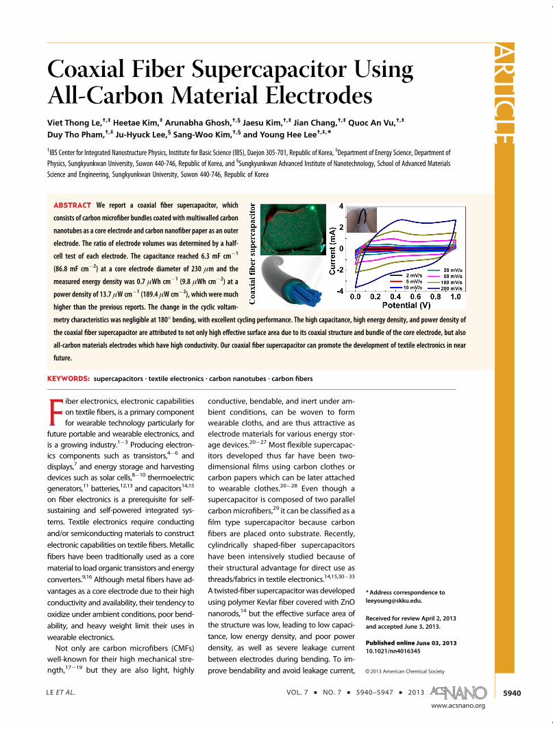
ABSTRACT We report a coaxial fiber supercapacitor, which
consists of carbon microfiber bundles coated with multiwalled carbon
nanotubes as a core electrode and carbon nanofiber paper as an outer
electrode. The ratio of electrode volumes was determined by a half-
cell test of each electrode. The capacitance reached 6.3 mF cm�1
(86.8 mF cm�2) at a core electrode diameter of 230 μm and the
measured energy density was 0.7 μWh cm�1 (9.8 μWh cm�2) at a
power density of 13.7 μW cm�1 (189.4 μW cm�2), which were much
higher than the previous reports. The change in the cyclic voltam-
metry characteristics was negligible at 180� bending, with excellent cycling performance. The high capacitance, high energy density, and power density ofthe coaxial fiber supercapacitor are attributed to not only high effective surface area due to its coaxial structure and bundle of the core electrode, but also
all-carbon materials electrodes which have high conductivity. Our coaxial fiber supercapacitor can promote the development of textile electronics in near
future.
KEYWORDS: supercapacitors . textile electronics . carbon nanotubes . carbon fibers
ARTIC
LE
LE ET AL. VOL. 7 ’ NO. 7 ’ 5940–5947 ’ 2013
www.acsnano.org
5941
two parallel plastic fibers coated with gold and gra-phite nanoparticles were used to make a flexible fibersupercapacitor by installing spacer wire to preventcontact.15 However, this supercapacitor still had lowcapacitance due to its parallel wire structure, limitednumber of fibers and low conductivity of plastic wires.In order to increase surface area, carbon nanotubefibers and graphene fibers have been used to makefiber supercapacitors.30�33 In addition to disadvan-tages of the twisted structures, the above-mentionedcapacitors also suffered from poor quality of fibers,which had lower tensile strength and lower conductiv-ity compared to CMFs.34,35 The choice of electrodematerials36�39 and structure is a key factor indeterminingthe energy and power density of fiber supercapacitor.Our aim is using CMFs to design a highly flexible
coaxial fiber supercapacitor with high energy densityand power density which can ultimately be woven intoself-powered wearable electronics. In this report, a coaxialfiber supercapacitor was fabricated using all carbon ma-terials. The structure of the developed supercapacitorconsisted of a CMF bundle coated with multiwalledcarbon nanotubes (MWCNTs) as a core electrode in thecenter of the coaxial supercapacitor and a carbon nano-fiber (CNF) film prepared by electrospinning as an outerelectrode. The fabricated coaxial-cable-type supercapaci-tor provides an efficient, flexible, wearable energy storagedevice which shows high capacitance, high energy andpower density, and good bendability.
RESULTS AND DISCUSSION
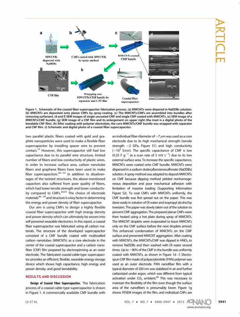
Design of Coaxial Fiber Supercapacitor. The fabricationprocess of a coaxial-cable-type supercapacitor is shownin Figure 1. A commercially available CMF bundle with
an individual fiber diameter of∼7μmwasused as a coreelectrode due to its high mechanical strength (tensilestrength ∼2 GPa, Figure S1) and high conductivity(∼103 S/cm). The specific capacitance of CMF is low(0.25 F g�1 at a scan rate of 5 mV s�1) due to its lowexternal surface area. To increase the specific capacitance,MWCNTs were coated onto CMF bundle. MWCNTs weredispersed in a sodiumdodecylbenzenesulfonate (NaDDBs)solution.A spraymethodwasadopted todepositMWCNTson CMF because dipping method yielded nonhomoge-neous deposition and poor mechanical adhesion withlimitation of massive loading (Supporting InformationFigure S2). To coat CMFs with MWCNTs uniformly, theCMF bundle was first spread out on the paper. This wasdone easily in solution of DIwater and isopropyl alcohol bytweezers. Thepaperwas slowly takenout of the solution toprevent CMF aggregation. The preparedplanar CMFswerethen heated using a hot plate during spray of MWCNTs.The MWCNT droplets were evaporated to leave MWCNTsonly on the CMF surface before the next droplets arrived.This enhanced condensation of MWCNTs on the CMFsurface and preventedMWCNT aggregation. After coatingwith MWCNTs, the MWCNTs/CMF was dipped in HNO3 toremove NaDDBs and then washed with DI water severaltimes. Up to∼90%of theCMF in thebundlewas uniformlycoated with MWCNTs, as shown in Figure 1d�f. Electro-spunCNF filmmadeofpolyacrylonitrile (PAN) polymerwasused as an outer electrode. PAN nanofiber film with atypical diameter of 200 nmwas stabilized in air and furthercarbonized under argon, which was different from typicalactivation under CO2 ambient.40 This was necessary tomaintain the flexibility of the film even though the surfacearea of the nanofibers is presumably lower. Figure 1gshows FESEM images of the film, and individual CNFs are
Figure 1. Schematic of the coaxial fiber supercapacitor fabrication process. (a) MWCNTs were dispered in NaDDBs solution.(b) MWCNTs are deposited onto planar CMFs by spray-coating. (c) The MWCNTs/CMFs are assembled into bundles afterremoving surfactant. (d and f) SEM images of single uncoated CMF and single CMF coated with MWCNTs. (e) SEM image of aMWCNTs/CMF bundle. (g) SEM image of a CNF film and its enlargement on upper right (the inset is a digital photo of thebendable CNF film). (h) After soaking with polymer electrolyte, the core MWCNTs/CMF bundle was wrapped with separatorand CNF film. (i) Schematic and digital photo of a coaxial fiber supercapacitor.
ARTIC
LE
LE ET AL. VOL. 7 ’ NO. 7 ’ 5940–5947 ’ 2013
www.acsnano.org
5942
shown in the inset. The bendability of the film is illustratedin the image in the left bottom inset, where the film isshown being bent using tweezers. The core and outerelectrodewere soakedwithpolymerelectrolyte, and thenaseparator and the outer electrode were wrapped in seriesaround the core electrode. The final coaxial-cable-typesupercapacitor is shown in Figure 1i. Diameter of the finalsupercapacitor was around 0.8 mm.
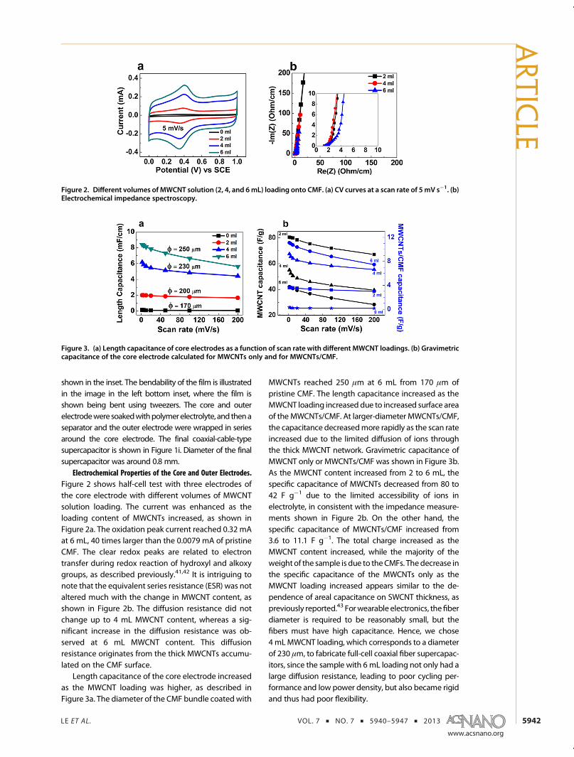
Electrochemical Properties of the Core and Outer Electrodes.Figure 2 shows half-cell test with three electrodes ofthe core electrode with different volumes of MWCNTsolution loading. The current was enhanced as theloading content of MWCNTs increased, as shown inFigure 2a. The oxidation peak current reached 0.32 mAat 6 mL, 40 times larger than the 0.0079 mA of pristineCMF. The clear redox peaks are related to electrontransfer during redox reaction of hydroxyl and alkoxygroups, as described previously.41,42 It is intriguing tonote that the equivalent series resistance (ESR) was notaltered much with the change in MWCNT content, asshown in Figure 2b. The diffusion resistance did notchange up to 4 mL MWCNT content, whereas a sig-nificant increase in the diffusion resistance was ob-served at 6 mL MWCNT content. This diffusionresistance originates from the thick MWCNTs accumu-lated on the CMF surface.
Length capacitance of the core electrode increasedas the MWCNT loading was higher, as described inFigure 3a. The diameter of the CMF bundle coatedwith
MWCNTs reached 250 μm at 6 mL from 170 μm ofpristine CMF. The length capacitance increased as theMWCNT loading increased due to increased surface areaof the MWCNTs/CMF. At larger-diameter MWCNTs/CMF,the capacitance decreasedmore rapidly as the scan rateincreased due to the limited diffusion of ions throughthe thick MWCNT network. Gravimetric capacitance ofMWCNT only or MWCNTs/CMF was shown in Figure 3b.As the MWCNT content increased from 2 to 6 mL, thespecific capacitance of MWCNTs decreased from 80 to42 F g�1 due to the limited accessibility of ions inelectrolyte, in consistent with the impedance measure-ments shown in Figure 2b. On the other hand, thespecific capacitance of MWCNTs/CMF increased from3.6 to 11.1 F g�1. The total charge increased as theMWCNT content increased, while the majority of theweight of the sample is due to theCMFs. Thedecrease inthe specific capacitance of the MWCNTs only as theMWCNT loading increased appears similar to the de-pendence of areal capacitance on SWCNT thickness, aspreviously reported.43 Forwearable electronics, thefiberdiameter is required to be reasonably small, but thefibers must have high capacitance. Hence, we chose4mLMWCNT loading, which corresponds to a diameterof 230 μm, to fabricate full-cell coaxial fiber supercapac-itors, since the sample with 6 mL loading not only had alarge diffusion resistance, leading to poor cycling per-formance and low power density, but also became rigidand thus had poor flexibility.
Figure 2. Different volumes of MWCNT solution (2, 4, and 6mL) loading onto CMF. (a) CV curves at a scan rate of 5mV s�1. (b)Electrochemical impedance spectroscopy.
Figure 3. (a) Length capacitance of core electrodes as a function of scan rate with different MWCNT loadings. (b) Gravimetriccapacitance of the core electrode calculated for MWCNTs only and for MWCNTs/CMF.
ARTIC
LE
LE ET AL. VOL. 7 ’ NO. 7 ’ 5940–5947 ’ 2013
www.acsnano.org
5943
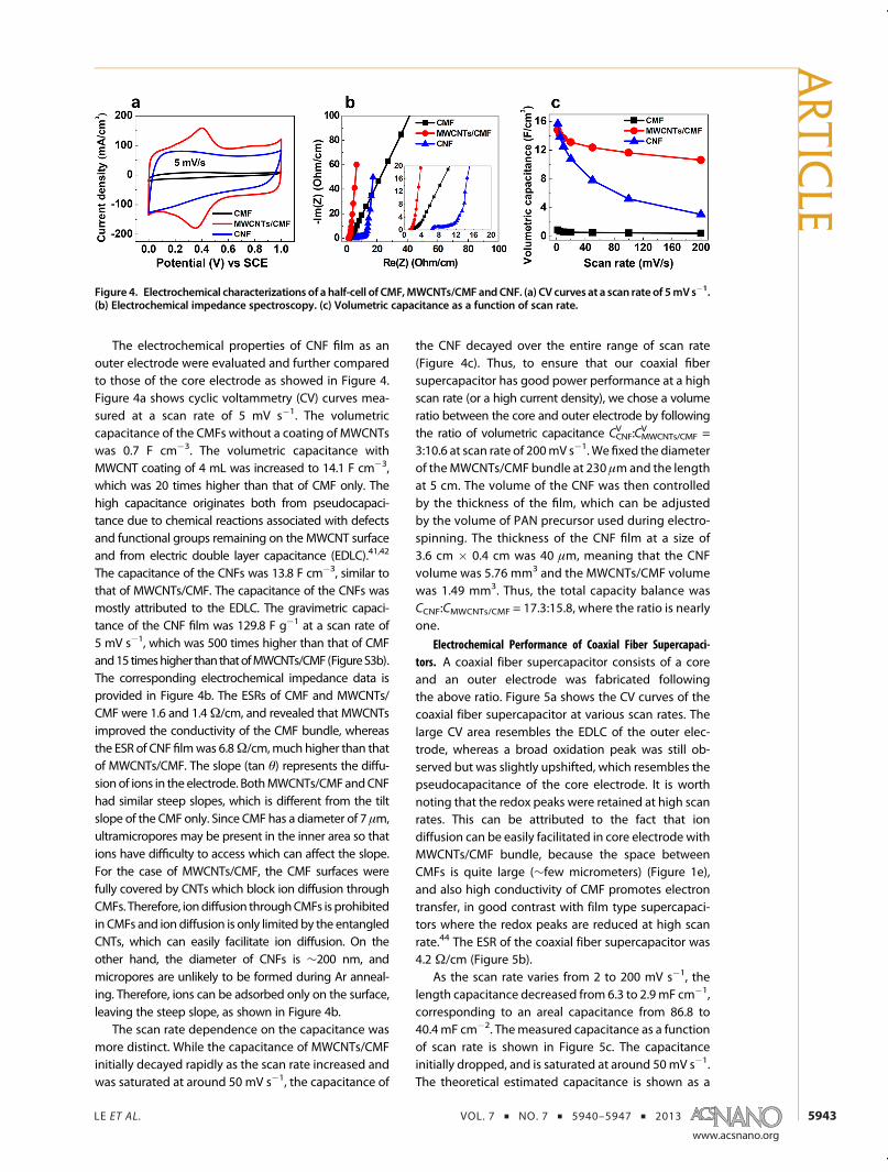
The electrochemical properties of CNF film as anouter electrode were evaluated and further comparedto those of the core electrode as showed in Figure 4.Figure 4a shows cyclic voltammetry (CV) curves mea-sured at a scan rate of 5 mV s�1. The volumetriccapacitance of the CMFs without a coating of MWCNTswas 0.7 F cm�3. The volumetric capacitance withMWCNT coating of 4 mL was increased to 14.1 F cm�3,which was 20 times higher than that of CMF only. Thehigh capacitance originates both from pseudocapaci-tance due to chemical reactions associated with defectsand functional groups remaining on the MWCNT surfaceand from electric double layer capacitance (EDLC).41,42
The capacitance of the CNFs was 13.8 F cm�3, similar tothat of MWCNTs/CMF. The capacitance of the CNFs wasmostly attributed to the EDLC. The gravimetric capaci-tance of the CNF film was 129.8 F g�1 at a scan rate of5 mV s�1, which was 500 times higher than that of CMFand15 timeshigher thanthatofMWCNTs/CMF (FigureS3b).The corresponding electrochemical impedance data isprovided in Figure 4b. The ESRs of CMF and MWCNTs/CMF were 1.6 and 1.4Ω/cm, and revealed that MWCNTsimproved the conductivity of the CMF bundle, whereasthe ESR of CNF filmwas 6.8Ω/cm,much higher than thatof MWCNTs/CMF. The slope (tan θ) represents the diffu-sion of ions in the electrode. BothMWCNTs/CMFandCNFhad similar steep slopes, which is different from the tiltslope of the CMF only. Since CMF has a diameter of 7 μm,ultramicropores may be present in the inner area so thations have difficulty to access which can affect the slope.For the case of MWCNTs/CMF, the CMF surfaces werefully covered by CNTs which block ion diffusion throughCMFs. Therefore, iondiffusion throughCMFs is prohibitedin CMFs and ion diffusion is only limited by the entangledCNTs, which can easily facilitate ion diffusion. On theother hand, the diameter of CNFs is ∼200 nm, andmicropores are unlikely to be formed during Ar anneal-ing. Therefore, ions can be adsorbed only on the surface,leaving the steep slope, as shown in Figure 4b.
The scan rate dependence on the capacitance wasmore distinct. While the capacitance of MWCNTs/CMFinitially decayed rapidly as the scan rate increased andwas saturated at around 50 mV s�1, the capacitance of
the CNF decayed over the entire range of scan rate(Figure 4c). Thus, to ensure that our coaxial fibersupercapacitor has good power performance at a highscan rate (or a high current density), we chose a volumeratio between the core and outer electrode by followingthe ratio of volumetric capacitance CCNF
V :CMWCNTs/CMFV =
3:10.6 at scan rate of 200mV s�1. We fixed the diameterof theMWCNTs/CMF bundle at 230 μmand the lengthat 5 cm. The volume of the CNF was then controlledby the thickness of the film, which can be adjustedby the volume of PAN precursor used during electro-spinning. The thickness of the CNF film at a size of3.6 cm � 0.4 cm was 40 μm, meaning that the CNFvolume was 5.76 mm3 and the MWCNTs/CMF volumewas 1.49 mm3. Thus, the total capacity balance wasCCNF:CMWCNTs/CMF = 17.3:15.8, where the ratio is nearlyone.
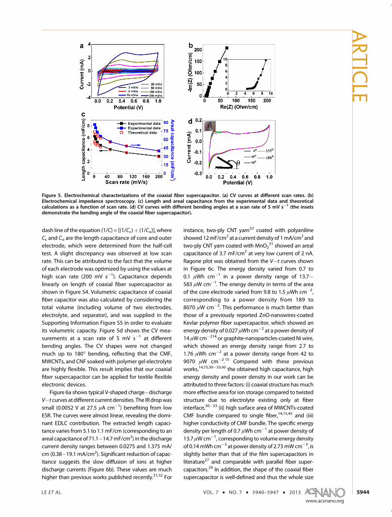
Electrochemical Performance of Coaxial Fiber Supercapaci-tors. A coaxial fiber supercapacitor consists of a coreand an outer electrode was fabricated followingthe above ratio. Figure 5a shows the CV curves of thecoaxial fiber supercapacitor at various scan rates. Thelarge CV area resembles the EDLC of the outer elec-trode, whereas a broad oxidation peak was still ob-served but was slightly upshifted, which resembles thepseudocapacitance of the core electrode. It is worthnoting that the redox peaks were retained at high scanrates. This can be attributed to the fact that iondiffusion can be easily facilitated in core electrode withMWCNTs/CMF bundle, because the space betweenCMFs is quite large (∼few micrometers) (Figure 1e),and also high conductivity of CMF promotes electrontransfer, in good contrast with film type supercapaci-tors where the redox peaks are reduced at high scanrate.44 The ESR of the coaxial fiber supercapacitor was4.2 Ω/cm (Figure 5b).
As the scan rate varies from 2 to 200 mV s�1, thelength capacitance decreased from 6.3 to 2.9mF cm�1,corresponding to an areal capacitance from 86.8 to40.4mF cm�2. Themeasured capacitance as a functionof scan rate is shown in Figure 5c. The capacitanceinitially dropped, and is saturated at around 50mV s�1.The theoretical estimated capacitance is shown as a
Figure 4. Electrochemical characterizations of a half-cell of CMF,MWCNTs/CMF andCNF. (a) CV curves at a scan rate of 5mVs�1.(b) Electrochemical impedance spectroscopy. (c) Volumetric capacitance as a function of scan rate.
ARTIC
LE
LE ET AL. VOL. 7 ’ NO. 7 ’ 5940–5947 ’ 2013
www.acsnano.org
5944
dash line of the equation (1/C) = [(1/Cc)þ (1/Co)], whereCc and Co are the length capacitance of core and outerelectrode, which were determined from the half-celltest. A slight discrepancy was observed at low scanrate. This can be attributed to the fact that the volumeof each electrode was optimized by using the values athigh scan rate (200 mV s�1). Capacitance dependslinearly on length of coaxial fiber supercapacitor asshown in Figure S4. Volumetric capacitance of coaxialfiber capacitor was also calculated by considering thetotal volume (including volume of two electrodes,electrolyte, and separator), and was supplied in theSupporting Information Figure S5 in order to evaluateits volumetric capacity. Figure 5d shows the CV mea-surements at a scan rate of 5 mV s�1 at differentbending angles. The CV shapes were not changedmuch up to 180� bending, reflecting that the CMF,MWCNTs, and CNF soakedwith polymer gel electrolyteare highly flexible. This result implies that our coaxialfiber supercapacitor can be applied for textile flexibleelectronic devices.
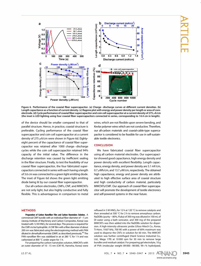
Figure 6a shows typical V-shaped charge�dischargeV�t curves at different currentdensities. The IRdropwassmall (0.0052 V at 27.5 μA cm�1) benefiting from lowESR. The curves were almost linear, revealing the domi-nant EDLC contribution. The extracted length capaci-tance varies from 5.1 to 1.1mF/cm (corresponding to anareal capacitanceof 71.1�14.7mF/cm2) in thedischargecurrent density ranges between 0.0275 and 1.375 mA/cm (0.38�19.1 mA/cm2). Significant reduction of capac-itance suggests the slow diffusion of ions at higherdischarge currents (Figure 6b). These values are muchhigher than previous works published recently.31,32 For
instance, two-ply CNT yarn32 coated with polyanilineshowed12mF/cm2 at a current densityof 1mA/cm2andtwo-ply CNT yarn coated with MnO2
31 showed an arealcapacitance of 3.7 mF/cm2 at very low current of 2 nA.Ragone plot was obtained from the V�t curves shownin Figure 6c. The energy density varied from 0.7 to0.1 μWh cm�1 in a power density range of 13.7�583 μW cm�1. The energy density in terms of the areaof the core electrode varied from 9.8 to 1.5 μWh cm�2,corresponding to a power density from 189 to8070 μW cm�2. This performance is much better thanthose of a previously reported ZnO-nanowires-coatedKevlar polymer fiber supercapacitor, which showed anenergy density of 0.027 μWhcm�2 at a power density of14 μWcm�214 or graphite-nanoparticles-coated Ni wire,which showed an energy density range from 2.7 to1.76 μWh cm�2 at a power density range from 42 to9070 μW cm�2.15 Compared with these previousworks,14,15,30�33,45 the obtained high capacitance, highenergy density and power density in our work can beattributed to three factors: (i) coaxial structure hasmuchmore effective area for ion storage compared to twistedstructure due to electrolyte existing only at fiberinterface,30�33 (ii) high surface area of MWCNTs-coatedCMF bundle compared to single fiber,14,15,45 and (iii)higher conductivity of CMF bundle. The specific energydensity per length of 0.7 μWh cm�1 at power density of13.7 μWcm�1, corresponding to volume energy densityof 0.14mWh cm�3 at power density of 2.73mWcm�3, isslightly better than that of the film supercapacitors inliterature27 and comparable with parallel fiber super-capacitors.29 In addition, the shape of the coaxial fibersupercapacitor is well-defined and thus the whole size
Figure 5. Electrochemical characterizations of the coaxial fiber supercapacitor. (a) CV curves at different scan rates. (b)Electrochemical impedance spectroscopy. (c) Length and areal capacitance from the experimental data and theoreticalcalculations as a function of scan rate. (d) CV curves with different bending angles at a scan rate of 5 mV s�1 (the insetsdemonstrate the bending angle of the coaxial fiber supercapacitor).
ARTIC
LE
LE ET AL. VOL. 7 ’ NO. 7 ’ 5940–5947 ’ 2013
www.acsnano.org
5945
of the device should be smaller compared to that ofparallel structure. Hence, in practice, coaxial structure ispreferable. Cycling performance of the coaxial fibersupercapacitor and coin cell supercapacitor at a currentdensity of 275 μA/cm were shown in Figure 6d. Eighty-eight percent of the capacitance of coaxial fiber super-capacitor was retained after 1000 charge�dischargecycles while the coin cell supercapacitor retained 94%capacity of the initial value. The difference in thedischarge retention was caused by inefficient sealingin the fiber structure. Finally, to test the feasibility of ourcoaxial fiber supercapacitor, the four fabricated super-capacitors connected in serieswith eachhaving a lengthof 3.6 cmwas connected to a green light emitting diode.The inset of Figure 6d shows the green light emittingdiode being lit by our coaxial fiber supercapacitor.
Our all-carbon electrodes, CMFs, CNF, andMWCNTsare not only light, but also highly conductive and fullyflexible. This is advantageous in comparison to metal
wires, which are not flexible upon severe bending, andKevlar polymerwireswhich are not conductive. Therefore,our all-carbon materials and coaxial-cable-type superca-pacitor is considered to be feasible for use in self-sustain-able textile electronics.
CONCLUSION
We have fabricated coaxial fiber supercapacitorusing all carbon material electrodes. Our supercapaci-tor showed good capacitance, high energy density andpower density with excellent flexibility. Length capac-itance, energy density, and power density are 5.1mF/cm,0.7 μWh/cm, and 13.7 μW/cm, respectively. The obtainedhigh capacitance, energy and power density are attrib-uted to high effective surface area of coaxial structureand high conductivity of carbon material, particularlyMWCNTs/CMF. Our approach of coaxial fiber supercapa-citor will promote the development of textile electronicsand self-powered systems in the near future.
METHODSPreparation of Carbon Nanofiber Film and Carbon Nanotubes Solution. A
commercial CMF bundlewith an individual fiber diameter of∼7 μm(Jeonju Institute of Machinery and Carbon Composites, Korea) wastreatedwith 12MHNO3 for several days. This process is required fortheCMFs tobehydrophilic. ACNF filmwitha fiberdiameterof about200 nmwas fabricated using the electrospinningmethodwith PANdiluted in dimethylformamide (DMF) as described previously.40 ThePAN nanofiber film was stabilized in air at 280 �C for 1 h and wascarbonized at 800 �C under argon for 1 h.
For preparing the carbon nanotubes solution, MWCNTswithan outer diameter of 10�15 nm (CM 95, Hanwha, Korea) were
refluxed in 5 M HNO3 for 12 h at 120 �C to remove catalysts andthen annealed at 500 �C for 2 h to remove amorphous carbon.NaDDBs (purity∼80%, Fluka) of 300mgwas diluted in 100mLofDI water using a bath sonicator, and 300 mg of the preparedMWCNTs was then added into the NaDDBs solution for disper-sion. A high-intensity ultrasonic probe (Ulsso Hitech Co., Korea,Ti-Horn, 19.87 kHz, 700 W) with a power of 60% maximum wasused to disperse the CNTs in solution for 60 min. The MWCNTsolution was further centrifuged (Hanil Science Industrial Co.,Ltd., Mega 17R) at 10 000 rpm for 30 min to remove largebundles and residual catalyst. For preparing gel electrolyte, 10 gof PVA (molecular weight 89 000�98 000, 99þ% hydrolyzed,
Figure 6. Performance of the coaxial fiber supercapacitor. (a) Charge�discharge curves at different current densities. (b)Length capacitance as a function of current density. (c) Ragone plot with energy and power density per length or area of core-electrode. (d) Cycle performance of coaxial fiber supercapacitor and coin cell supercapacitor at a current density of 275 μA/cm(the inset is LED lighting using four coaxial fiber supercapacitors connected in series, corresponding to 14.4 cm in length).
ARTIC
LE
LE ET AL. VOL. 7 ’ NO. 7 ’ 5940–5947 ’ 2013
www.acsnano.org
5946
Aldrich) was diluted into 100 mL of DI water, and 10 g ofconcentrated H3PO4 was then added. This solution was stirredfor 3 h at 90 �C to obtain a clear solution.
Fabrication Process of the Coaxial Fiber Supercapacitor. A CMFbundle composed of about 550 fibers with a length of 5 cmwas pressed by tweezers to spread the bundle into individual orvery small bundles prior to spraying the CNT solution. Thespread CMFs were suspended on a hot plate in air. Differentvolumes of MWCNT solution (2, 4, and 6 mL) were coated onboth sides of the CMFs by the spray method. These volumescorrespond to CNT weight percents of 4.5, 16.8, and 26.3 wt %.The flattened CMFs coated with MWCNTs were dipped in 5 MHNO3 for 4 h to remove the surfactant. This again functionalizedMWCNTs. The MWCNTs-coated CMF were lightly twisted toform a round bundle for use as the core electrode in a coaxialsupercapacitor. The weight of the MWCNTs was measured bythe weight difference of the CMF bundle before and afterMWCNT deposition. CNF film with a thickness of 40 μm wascut into 3.6 cm� 0.4 cm pieces. The core electrode and cut CNFfilm were dipped into gel electrolyte and then transferred into alow vacuum chamber for 0.5 h so that the electrolyte could soakinto the pores of the electrodes. After removing from the ovenand letting sit for about 20 min, a separator (Celgard 3501,Celgard USA) was rolled around the core electrode and the cutCNF film was rolled on the outside. In this case, the polymer gelelectrolyte acted as a glue to attach the outer electrode well.
Characterization. The morphology of the two electrodes wasobserved by field emission scanning electron microscopy(FESEM, JEOL JSM7000F, Japan), and the capacitive perfor-mance of samples was characterized using CV measurementsystem (Biologic VMP3, France). The electrochemical impe-dance spectroscopy was measured with a frequency range of10 kHz to 10 mHz. For the half-cell test, a gold wire was used toconnect the core electrode. A custom Teflon cell was used forthe coin-type CNF film. A three-electrode configuration wasused, with a platinum wire counter electrode and an Ag/AgClreference electrode, and a MWCNTs-coated CMF bundle or CNFfilm as the working electrode. For the coaxial fiber supercapac-itor test, the two electrodes of the CV system were connecteddirectly to the core and outer electrode of coaxial fiber super-capacitor. To demonstrate the feasibility of the coaxial fiber super-capacitor, a commercial green light emitting diode was used.
Conflict of Interest: The authors declare no competingfinancial interest.
Acknowledgment. Authors acknowledge Prof. DongSeokSuh for helpful discussion. This work was supported by theInstitute for Basic Science (IBS) in Korea and WCU (World ClassUniversity) program through the National Research Foundationof Korea funded by the Ministry of Education, Science andTechnology (R31-2008-10029). S.-W.K. acknowledges financialsupport by Basic Science Research Program through the NRFgrant funded by the MEST (2010-0015035).
Supporting Information Available: Calculation method; pre-paration of coin cell; stress�strain curve of CMF; MWCNTloading onto CMF by dipping method; gravimetric capacitanceof core and outer electrodes; capacitance as a function oflength; volumetric capacitance of coaxial fiber supercapacitor.This material is available free of charge via the Internet at http://pubs.acs.org.
REFERENCES AND NOTES1. Robert, F. S. Electronic Textiles Charge Ahead. Science
2003, 301, 909–911.2. Hamedi, M.; Forchheimer, R.; Inganäs, O. Towards Woven
Logic from Organic Electronic Fibres. Nat. Mater. 2007, 6,357–362.
3. Rossi, D. D. Electronic Textiles: A Logical Step. Nat. Mater.2007, 6, 328–329.
4. Hamedi, M.; Herlogsson, L.; Crispin, X.; Marcilla, R.; Berggren,M.; Inganäs, O. Fiber-Embedded Electrolyte-Gated Field-Effect Transistors for E-Textiles. Adv. Mater. 2009, 21, 573–577.
5. Maccioni, M.; Orgiu, E.; Cosseddu, P.; Locci, S.; Bonfiglio, A.Towards the Textile Transistor: Assembly and Character-ization of an Organic Field Effect Transistor with a Cylind-rical Geometry. Appl. Phys. Lett. 2006, 89, 143515.
6. Müller, C.; Hamedi, M.; Karlsson, R.; Jansson, R.; Marcilla, R.;Hedhammar, M.; Inganäs, O. Woven Electrochemical Tran-sistors on Silk Fibers. Adv. Mater. 2011, 23, 898–901.
7. O'Connor, B.; An, K. H.; Zhao, Y.; Pipe, K. P.; Shtein, M. FiberShaped Light Emitting Device. Adv. Mater. 2007, 19, 3897–3900.
8. Kaltenbrunner, M.; White, M. S.; Gzowacki, E. D.; Sekitani, T.;Someya, T.; Sariciftci, N. S.; Bauer, S. Ultrathin and Light-weight Organic Solar Cells with High Flexibility. Nat.Commun. 2012, 3, 770.
9. Lee, M. R.; Eckert, R. D.; Forberich, K.; Dennler, G.; Brabec,C. J.; Gaudiana, R. A. Solar Power Wires Based on OrganicPhotovoltaic Materials. Science 2009, 324, 232–235.
10. O'Connor, B.; Pipe, K. P.; Shtein, M. Fiber Based OrganicPhotovoltaic Devices. Appl. Phys. Lett. 2008, 92, 193306.
11. Yadav, A.; Pipe, K. P.; Shtein, M. Fiber-Based FlexibleThermoelectric Power Generator. J. Power Sources 2008,175, 909–913.
12. Bhattacharya, R.; Kok, M. M. de; Zhou, J. RechargeableElectronic Textile Battery. Appl. Phys. Lett. 2009, 95, 223305.
13. Kwon, Y. H.; Woo, S.-W.; Jung, H.-R.; Yu, H. K.; Kim, K.; Oh,B. H.; Ahn, S.; Lee, S.-Y.; Song, S.-W.; Cho, J.; et al. Cable-TypeFlexible Lithium Ion Battery Based on Hollow Multi-HelixElectrodes. Adv. Mater. 2012, 24, 5192–5197.
14. Bae, J.; Song, M. K.; Park, Y. J.; Kim, J. M.; Liu, M.; Wang, Z. L.Fiber Supercapacitors Made of Nanowire-Fiber HybridStructures for Wearable/Flexible Energy Storage. Angew.Chem., Int. Ed. 2011, 50, 1683–1687.
15. Fu, Y.; Cai, X.; Wu, H.; Lv, Z.; Hou, S.; Peng, M.; Yu, X.; Zou, D.Fiber Supercapacitors Utilizing Pen Ink for Flexible/Wear-able Energy Storage. Adv. Mater. 2012, 24, 5713–5718.
16. Nam, S.; Jang, J.; Park, J.-J.; Kim, S. W.; Park, C. E.; Kim, J. M.High-Performance Low-Voltage Organic Field-Effect Tran-sistors Prepared on Electro-Polished AluminumWires. ACSAppl. Mater. Interfaces 2012, 4, 6–10.
17. Chae, H. G.; Kumar, S. Making Strong Fibers. Science 2008,319, 908–909.
18. Koziol, K.; Vilatela, J.; Moisala, A.; Motta, M.; Cunniff, P.;Sennett, M.; Windle, A. High-Performance Carbon Nano-tube Fiber. Science 2007, 318, 1892–1895.
19. Khan, U.; Young, K.; O'Neill, A.; Coleman, J. N. High StrengthComposite Fibres from Polyester Filled with Nanotubesand Graphene. J. Mater. Chem. 2012, 22, 12907–12914.
20. Hu, L.; Chen, W.; Xie, X.; Liu, N.; Yang, Y.; Wu, H.; Yao, Y.; Pasta,M.; Alshareef, H. N.; Cui, Y. Symmetrical MnO2-Carbon Nano-tube-Textile Nanostructures for Wearable Pseudocapacitorswith High Mass Loading. ACS Nano 2011, 5, 8904–8913.
21. Yu,G.;Hu, L.; Vosgueritchian,M.;Wang,H.; Xie, X.;McDonough,J. R.; Cui, X.; Cui, Y.; Bao, Z. Solution-Processed Graphene/MnO2 Nanostructured Textiles for High-PerformanceElectrochemical Capacitors. Nano Lett. 2011, 11, 2905–2911.
22. Lu, X.; Wang, G.; Zhai, T.; Yu, M.; Xie, S.; Ling, Y.; Liang, C.;Tong, Y.; Li, Y. Stabilized TiN Nanowire Arrays for High-performance and Flexible Supercapacitors. Nano Lett.2012, 12, 5376–5381.
23. Lu, X.; Zhai, T.; Zhang, X.; Shen, Y.; Yuan, L.; Hu, B.; Gong, L.;Chen, J.; Gao, Y.; Zhou, J.; et al. WO3‑x@Au@MnO2 Core-Shell Nanowires on Carbon Fabric for High-PerformanceFlexible Supercapacitors. Adv. Mater. 2012, 24, 938–944.
24. Cheng, Q.; Tang, J.; Ma, J.; Zhang, H.; Shinya, N.; Qin, L.-C.Polyaniline-Coated Electro-Etched Carbon Fiber ClothElectrodes for Supercapacitors. J. Phys . Chem. C 2011,115, 23584–23590.
25. Hu, L.; Pasta, M.; Mantia, F. L.; Cui, L.; Jeong, S.; Deshazer,H. D.; Choi, J. W.; Han, S. M.; Cui, Y. Stretchable, Porous, andConductive Energy Textiles. Nano Lett. 2010, 10, 708–714.
26. Yuan, L.; Lu, X.-H.; Xiao, X.; Zhai, T.; Dai, J.; Zhang, F.; Hu, B.;Wang, X.; Gong, L.; Chen, J.; et al. Flexible Solid-StateSupercapacitors Based on Carbon Nanoparticles/MnO2
Nanorods Hybrid Structure. ACS Nano 2012, 6, 656–661.
ARTIC
LE
LE ET AL. VOL. 7 ’ NO. 7 ’ 5940–5947 ’ 2013
www.acsnano.org
5947
27. Yang, P.; Xiao, X.; Li, Y.; Ding, Y.; Qiang, P.; Tan, X.; Mai, W.;Lin, Z.; Wu, W.; Li, T.; et al. Hydrogenated ZnO Core-ShellNanocables for Flexible Supercapacitors and Self-PoweredSystems. ACS Nano 2013, 7, 2617–2626.
28. Yuan, L.; Xiao, X.; Ding, T.; Zhong, J.; Zhang, X.; Shen, Y.; Hu,B.; Huang, Y.; Zhou, J.; Wang, Z. L. Paper-Based Super-capacitors for Self-Powered Nanosystems. Angew. Chem.,Int. Ed. 2012, 51, 4934–4938.
29. Xiao, X.; Li, T.; Yang, P.; Gao, Y.; Jin, H.; Ni, W.; Zhan, W.;Zhang, X.; Cao, Y.; Zhong, J.; et al. Fiber-Based All-Solid-State Flexible Supercapacitors for Self-Powered Systems.ACS Nano 2012, 6, 9200–9206.
30. Chen, T.; Qiu, L.; Yang, Z.; Cai, Z.; Ren, J.; Li, H.; Lin, H.; Sun, X.;Peng, H. An Integrated “Energy Wire” for Both Photo-electric Conversion and Energy Storage. Angew. Chem.,Int. Ed. 2012, 51, 11977–11980.
31. Ren, J.; Li, L.; Chen, C.; Chen, X.; Cai, Z.; Qiu, L.; Wang, Y.; Zhu,X.; Peng, H. Twisting Carbon Nanotube Fibers for BothWire-Shaped Micro-Supercapacitor and Micro-Battery.Adv. Mater. 2013, 25, 1155–1159.
32. Wang, K.; Meng, Q.; Zhang, Y.; Wei, Z.; Miao, M. High-Performance Two-Ply Yarn Supercapacitors Based onCarbon Nanotubes and Polyaniline Nanowire Arrays.Adv. Mater. 2013, 25, 1494–1498.
33. Meng, Y.; Zhao, Y.; Hu, C.; Cheng, H.; Hu, Y.; Zhang, Z.; Shi,G.; Qu, L. All-Graphene Core-Sheath Microfibers for All-Solid-State, Stretchable Fibriform Supercapacitors andWearable Electronic Textiles. Adv. Mater. 2013, 25, 2326–2331.
34. Zhang, M.; Atkinson, K. R.; Baughman, R. H. MultifunctionalCarbon Nanotube Yarns by Downsizing an Ancient Tech-nology. Science 2004, 306, 1358–1361.
35. Zhang, X.; Jiang, K.; Feng, C.; Liu, P.; Zhang, L.; Kong, J.;Zhang, T.; Li, Q.; Fan, S. Spinning and Processing Contin-uous Yarns from 4-InchWafer Scale Super-Aligned CarbonNanotube Arrays. Adv. Mater. 2006, 18, 1505–1510.
36. Simon, P.; Gogotsi, Y. Materials for ElectrochemicalCapacitors. Nat. Mater. 2008, 7, 845–854.
37. Liu, C.; Li, F.; Ma, L.-P.; Cheng, H.-M. Advanced Materials forEnergy Storage. Adv. Mater. 2010, 22, E28–E62.
38. Wang, G.; Zhang, L.; Zhang, J. A Review of ElectrodeMaterials for Electrochemical Supercapacitors. Chem. Soc.Rev. 2012, 41, 797–828.
39. Ghosh, A.; Lee, Y. H. Carbon-Based ElectrochemicalCapacitors. ChemSusChem 2012, 5, 480–499.
40. Ra, E. J.; Raymundo-Pi~nero, E.; Lee, Y. H.; Béguin, F. HighPower Supercapacitors Using Polyacrylonitrile-Based Car-bon Nanofiber Paper. Carbon 2009, 47, 2984–2992.
41. Frackowiak, E.; Metenier, K.; Bertagna, V.; Beguin, F. Super-capacitor Electrodes fromMultiwalled Carbon Nanotubes.Appl. Phys. Lett. 2000, 77, 2421.
42. Pan, H.; Poh, C. K.; Feng, Y. P.; Lin, J. SupercapacitorElectrodes from Tubes-in-Tube Carbon Nanostructures.Chem. Mater. 2007, 19, 6120–6125.
43. Kaempgen, M.; Chan, C. K.; Ma, J.; Cui, Y.; Gruner, G.Printable Thin Film Supercapacitors Using Single-WalledCarbon Nanotubes. Nano Lett. 2009, 9, 1872–1876.
44. Zhao, X.; Chu, B. T. T.; Ballesteros, B.; Wang,W.; Johnston, C.;Sykes, J. M.; Grant, P. S. Spray Deposition of Steam Treatedand Functionalized Single-Walled and Multi-Walled Car-bon Nanotube Films for Supercapacitors. Nanotechnology2009, 20, 065605–065613.
45. Bae, J.; Park, Y. J.; Lee, M.; Cha, S. N.; Choi, Y. J.; Lee, C. S.; Kim,J. M.; Wang, Z. L. Single-Fiber-Based Hybridization ofEnergy Converters and Storage Units Using Graphene asElectrodes. Adv. Mater. 2011, 23, 3446–3449.
ARTIC
LE


![Terahertz electromagnetic crystal waveguide fabricated by ...€¦ · [5], metal wire [6, 7], coaxial transmission line [8], sub-wavelength fiber [2, 9–11], photonic crystal fiber](https://img.pdfslide.net/doc/110x75/5fc79678232a637257064bbe/terahertz-electromagnetic-crystal-waveguide-fabricated-by-5-metal-wire-6.jpg)