Embed Size (px)
Citation preview
I N S T R U C T I O N M A N U A L
www.suunto.com
C O B R A
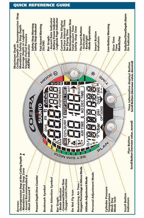
Arr
ow
s:- D
eco
mp
ress
ion
Sto
p a
t th
e C
eilin
g D
epth
- M
an
dato
ry S
afe
ty S
top
Zo
ne
- A
scen
t R
eco
mm
en
ded
- M
ust
Desc
en
d
QUICK REFERENCE GUIDE
bar
psi
°F°C
ft
MA
XA
VG
PO
2
NO
DE
C T
IME
ST
OP
AIR
TIM
E
TIM
E
SU
RF
DIV
E
O2%
AS
C T
IME
CE
ILIN
G
OKQU
IT
SELE
CT
OP
TIO
NS
NO
S L O W
TC B
OL
F
DIV
E
m
°Cb
ar
Low
Bat
tery
War
nin
gC
yli
nd
er
Pre
ssu
reTe
mp
era
ture
Week D
ay
Mo
de T
ext
Pers
on
al A
dju
stm
en
t M
od
e
Do
No
t Fl
y I
con
Bar
Gra
ph
:-
Mo
de I
nd
icato
r- C
onsu
med
Bott
om
Tim
e- O
xyg
en L
imit
Fra
ctio
n
Bar
Gra
ph
:-
Asc
en
t R
ate
In
dic
ato
r- B
atte
ry P
ow
er In
dic
ato
r- L
og
bo
ok
Pag
e In
dic
ato
r
Pres
ent D
epth
Div
e C
ou
nte
r
Pla
n B
utt
on
Scro
ll B
utt
on
(in
crea
se v
alu
e, a
scen
d)
Rem
ain
ing
Air
Tim
e /
Oxy
gen
Per
centa
ge
in N
itro
x M
ode
Cu
rren
t Ti
me D
isp
lay
Su
rface
In
terv
al
Tim
eN
o F
lyin
g T
ime
No-D
ecom
pre
ssio
n T
ime
Tota
l Asc
en
t Ti
me
Safe
ty S
top
Tim
e
Div
e T
ime
Tim
eM
ont
h,D
ay
The
Smar
t B
utt
on
:-
Act
ivati
on
- B
ack
lig
ht
- Mo
de
Op
erat
ion
s
Maxim
um
Dep
thC
eil
ing
Dep
th o
n D
eco
mp
ress
ion
Sto
pM
an
dato
ry S
afe
ty S
top
Dep
thA
vera
ge D
ep
th i
n L
og
bo
ok
Oxyg
en
Part
ial
Pre
ssu
reA
M/P
M I
nd
icato
r
Alt
itud
e A
dju
stm
ent M
od
e
Bo
okm
ark
Sym
bo
l
Dai
ly/D
iveT
ime/
Dep
th A
larm
On
In
dic
ato
r
Div
er
Att
en
tio
n S
ym
bo
l
Sm
art
Bu
tto
nIn
dic
ato
rs
Scr
oll
Bu
tto
nIn
dic
ato
rsTi
me (
alt
ern
ati
ve d
isp
lay)
Bu
tto
nSc
roll
Bu
tto
n (d
ecre
ase
valu
e, d
esce
nd
)
Fast
Asc
ent W
arn
ing
(SLO
W)
Safe
ty S
top
War
nin
gSa
fety
Sto
p In
dic
ator
1
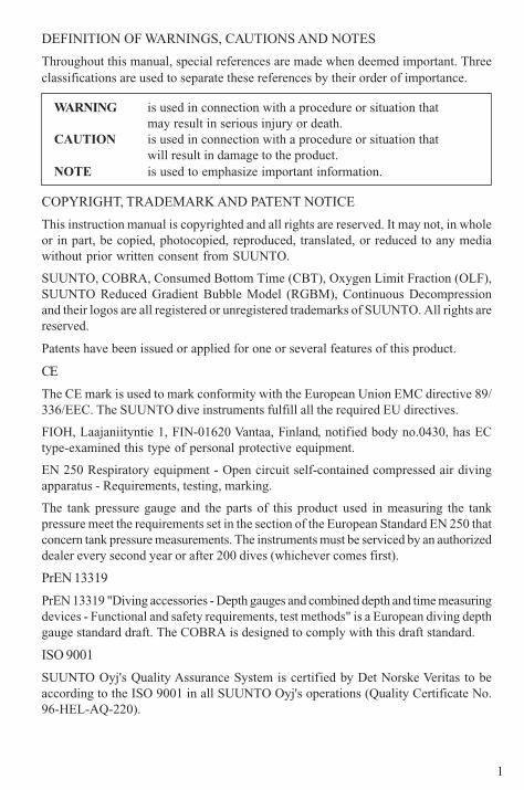
DEFINITION OF WARNINGS, CAUTIONS AND NOTES
Throughout this manual, special references are made when deemed important. Threeclassifications are used to separate these references by their order of importance.
WARNING is used in connection with a procedure or situation thatmay result in serious injury or death.
CAUTION is used in connection with a procedure or situation thatwill result in damage to the product.
NOTE is used to emphasize important information.
COPYRIGHT, TRADEMARK AND PATENT NOTICE
This instruction manual is copyrighted and all rights are reserved. It may not, in wholeor in part, be copied, photocopied, reproduced, translated, or reduced to any mediawithout prior written consent from SUUNTO.
SUUNTO, COBRA, Consumed Bottom Time (CBT), Oxygen Limit Fraction (OLF),SUUNTO Reduced Gradient Bubble Model (RGBM), Continuous Decompressionand their logos are all registered or unregistered trademarks of SUUNTO. All rights arereserved.
Patents have been issued or applied for one or several features of this product.
CE
The CE mark is used to mark conformity with the European Union EMC directive 89/336/EEC. The SUUNTO dive instruments fulfill all the required EU directives.
FIOH, Laajaniityntie 1, FIN-01620 Vantaa, Finland, notified body no.0430, has ECtype-examined this type of personal protective equipment.
EN 250 Respiratory equipment - Open circuit self-contained compressed air divingapparatus - Requirements, testing, marking.
The tank pressure gauge and the parts of this product used in measuring the tankpressure meet the requirements set in the section of the European Standard EN 250 thatconcern tank pressure measurements. The instruments must be serviced by an authorizeddealer every second year or after 200 dives (whichever comes first).
PrEN 13319
PrEN 13319 "Diving accessories - Depth gauges and combined depth and time measuringdevices - Functional and safety requirements, test methods" is a European diving depthgauge standard draft. The COBRA is designed to comply with this draft standard.
ISO 9001
SUUNTO Oyj's Quality Assurance System is certified by Det Norske Veritas to beaccording to the ISO 9001 in all SUUNTO Oyj's operations (Quality Certificate No.96-HEL-AQ-220).
2
WARNINGS
SUUNTO Oyj does not assume any responsibility for losses or claims by thirdparties, which may arise through the use of this device.
Due to continuous product development, the COBRA is subject to changewithout notice.
WARNING!
READ THIS MANUAL! Carefully read this instruction manual in its entiretypaying close attention to all warnings listed below, including section 1.1. "SafetyPrecautions". Make sure that you fully understand the use, displays andlimitations of the dive computer because any confusion resulting fromneglecting to follow this instruction manual or from improper use of this devicemay cause a diver to commit errors that may lead to serious injury or death.
WARNING!
NOT FOR PROFESSIONAL USE! Suunto dive computers are intended forrecreational use only. The demands of commercial or professional diving mayexpose the diver to depths and exposures that tend to increase the risk ofdecompression illness (DCI). Therefore, Suunto strongly recommends that thedevice be not used for commercial or professional diving activity.
WARNING!
ONLY DIVERS TRAINED IN THE PROPER USE OF SCUBA DIVINGEQUIPMENT SHOULD USE A DIVE COMPUTER! No dive computer canreplace the need for proper dive training. Insufficient or improper training maycause diver to commit errors that may lead to serious injury or death.
WARNING!
THERE IS ALWAYS A RISK OF DECOMPRESSION ILLNESS (DCI) FOR ANYDIVE PROFILE EVEN IF YOU FOLLOW THE DIVE PLAN PRESCRIBED BYDIVE TABLES OR A DIVE COMPUTER. NO PROCEDURE, DIVE COMPUTEROR DIVE TABLE WILL PREVENT THE POSSIBILITY OF DCI OR OXYGENTOXICITY! An individual's physiological make up can vary from day to day.The dive computer cannot account for these variations. You are strongly advisedto remain well within the exposure limits provided by the instrument to minimizethe risk of DCI. As an added measure of safety, you should consult a physicianregarding your fitness before diving.
3
WARNING!
SUUNTO STRONGLY RECOMMENDS THAT SPORT DIVERS LIMIT THEIRMAXIMUM DEPTH TO 40 M [130 FT] OR TO THE DEPTH CALCULATEDBY THE COMPUTER BASED ON THE SELECTED O2% AND A MAXIMUMPO2 OF 1.4 BAR SETTINGS!
WARNING!
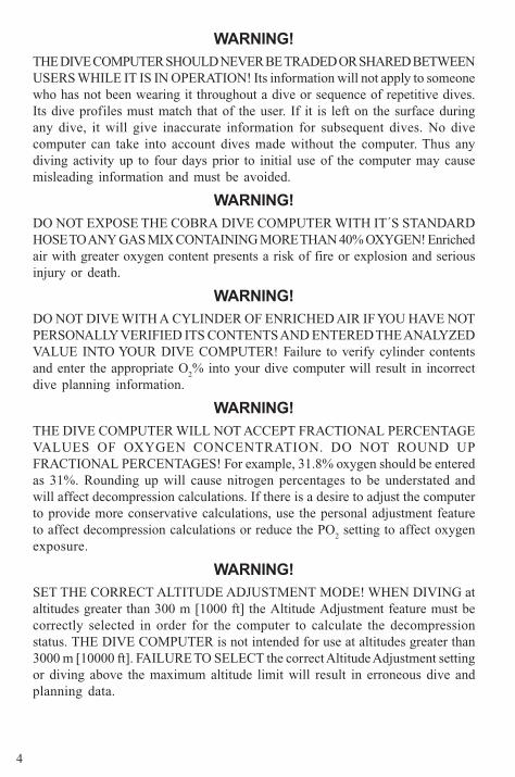
DIVES WITH REQUIRED DECOMPRESSION STOPS ARE NOTRECOMMENDED. YOU SHOULD ASCEND AND BEGIN DECOMPRESSIONIMMEDIATELY WHEN THE DIVE COMPUTER SHOWS YOU THAT ADECOMPRESSION STOP IS REQUIRED! Note the blinking ASC TIME symboland the upward pointing arrow.
WARNING!
USE BACK-UP INSTRUMENTS! Make sure that you use back-upinstrumentation including a depth gauge, submersible pressure gauge, timer orwatch, and have access to decompression tables whenever diving with thedive computer.
WARNING!
PERFORM PRECHECKS! Always activate and check the device before divingin order to ensure that all Liquid Crystal Display (LCD) segments are completelydisplayed, that the device has not run out of battery power, and that the oxygen,altitude and personal adjustments are correct. Also, exit the Data Transfermode before diving, as the computer does not automatically revert to Divemode from Data Transfer mode.
WARNING!
YOU ARE ADVISED TO AVOID FLYING ANY TIME THE COMPUTERCOUNTS DOWN THE NO-FLYING TIME. ALWAYS ACTIVATE THECOMPUTER TO CHECK THE REMAINING NO-FLY TIME PRIOR TO FLYING!The computer goes into the stand-by display automatically 5 minutes after thedive has ended. The stand-by display shuts off after two hours. Flying ortraveling to a higher altitude within no-fly time can greatly increase the risk ofDCI. Review the recommendations given by Diver's Alert Network (DAN) inchapter 3.6.3. "Flying After Diving". There can never be a flying after divingrule that is guaranteed to completely prevent decompression illness!
4
WARNING!
THE DIVE COMPUTER SHOULD NEVER BE TRADED OR SHARED BETWEENUSERS WHILE IT IS IN OPERATION! Its information will not apply to someonewho has not been wearing it throughout a dive or sequence of repetitive dives.Its dive profiles must match that of the user. If it is left on the surface duringany dive, it will give inaccurate information for subsequent dives. No divecomputer can take into account dives made without the computer. Thus anydiving activity up to four days prior to initial use of the computer may causemisleading information and must be avoided.
WARNING!
DO NOT EXPOSE THE COBRA DIVE COMPUTER WITH IT´S STANDARDHOSE TO ANY GAS MIX CONTAINING MORE THAN 40% OXYGEN! Enrichedair with greater oxygen content presents a risk of fire or explosion and seriousinjury or death.
WARNING!
DO NOT DIVE WITH A CYLINDER OF ENRICHED AIR IF YOU HAVE NOTPERSONALLY VERIFIED ITS CONTENTS AND ENTERED THE ANALYZEDVALUE INTO YOUR DIVE COMPUTER! Failure to verify cylinder contentsand enter the appropriate O
2% into your dive computer will result in incorrect
dive planning information.
WARNING!
THE DIVE COMPUTER WILL NOT ACCEPT FRACTIONAL PERCENTAGEVALUES OF OXYGEN CONCENTRATION. DO NOT ROUND UPFRACTIONAL PERCENTAGES! For example, 31.8% oxygen should be enteredas 31%. Rounding up will cause nitrogen percentages to be understated andwill affect decompression calculations. If there is a desire to adjust the computerto provide more conservative calculations, use the personal adjustment featureto affect decompression calculations or reduce the PO
2 setting to affect oxygen
exposure.
WARNING!
SET THE CORRECT ALTITUDE ADJUSTMENT MODE! WHEN DIVING ataltitudes greater than 300 m [1000 ft] the Altitude Adjustment feature must becorrectly selected in order for the computer to calculate the decompressionstatus. THE DIVE COMPUTER is not intended for use at altitudes greater than3000 m [10000 ft]. FAILURE TO SELECT the correct Altitude Adjustment settingor diving above the maximum altitude limit will result in erroneous dive andplanning data.
5
WARNING!
SET THE CORRECT PERSONAL ADJUSTMENT MODE!, Whenever it isbelieved that factors that tend to increase the possibility of DCI exist, it isrecommended that you use this option to make the calculations moreconservative. Failure to select the correct Personal Adjustment setting willresult in erroneous dive and planning data.
NOTE!
It is not possible to change between Air, Nitrox and Gauge modes before theinstrument has counted down the no-flying time.
There is one exception to this: You can change from Air to Nitrox mode evenduring the no-flying time. When planning both air and nitrox dives during thesame dive series, you should set the instrument in Nitrox mode and modify thegas mix accordingly.
In Gauge mode, the no-flying time is always 48 hours.
6
TABLE OF CONTENTS
WARNINGS .................................................................................... 1
1. INTRODUCTION ...................................................................... 8
1.1. SAFETY PRECAUTIONS ....................................................................... 91.1.1. Emergency Ascents ..................................................................91.1.2. Dive Computer Limitations .......................................................91.1.3. Nitrox ....................................................................................... 10
2. GETTING ACQUAINTED ...................................................... 11
2.1. FUNCTIONS .......................................................................................... 112.2. CONNECTING THE COBRA TO A REGULATOR .......................... 112.3. PUSH BUTTONS .................................................................................. 122.4. WATER CONTACTS ............................................................................ 13
3. DIVING WITH THE COBRA................................................. 14
3.1. BEFORE DIVING .................................................................................. 143.1.1. Activation and Prechecks ...................................................... 143.1.2. Battery Power Indicator and Low Battery Warning ............. 153.1.3. Dive Planning [PLAN] ............................................................ 163.1.4. User Definable Functions and Alarms .................................. 17
3.2. SAFETY STOPS ..................................................................................... 183.2.1. Recommended Safety Stop .................................................... 183.2.2. Mandatory Safety Stop .......................................................... 18
3.3. DIVING IN AIR MODE ....................................................................... 203.3.1. Basic Dive Data ....................................................................... 203.3.2. Bookmark ................................................................................. 213.3.3. Cylinder Pressure Data ........................................................... 213.3.4. Consumed Bottom Time (CBT) .............................................. 233.3.5. Ascent Rate Indicator ............................................................. 233.3.6. Decompression dives ............................................................. 24
3.4. DIVING IN NITROX MODE ............................................................... 283.4.1. Before Diving .......................................................................... 283.4.2. Oxygen Displays ..................................................................... 293.4.3. Oxygen Limit Fraction (OLF) .................................................. 30
3.5. DIVING IN GAUGE MODE ................................................................ 313.6. AT THE SURFACE ............................................................................... 32
3.6.1. Surface Interval ....................................................................... 323.6.2. Dive Numbering ...................................................................... 333.6.3. Flying After Diving ................................................................. 34
3.7. AUDIBLE AND VISUAL ALARMS ............................................... 353.8. HIGH ALTITUDE DIVES AND PERSONAL ADJUSTMENT ....... 37
3.8.1. Altitude Adjustment ............................................................... 373.8.2. Personal Adjustment .............................................................. 38
3.9. ERROR CONDITIONS ......................................................................... 39
7
4. MENU BASED MODES ......................................................... 40
4.1. MEMORIES AND DATA TRANSFER [1 MEMORY] ...................... 424.1.1. Logbook and Dive Profile Memory [1 LOGBOOK] .............. 424.1.2. Dive History Memory [2 HISTORY] ...................................... 454.1.3. Data Transfer and PC-Interface [3 TR-PC] ............................ 45
4.2. SIMULATION MODE [2 SIMUL] ...................................................... 474.2.1. Dive Simulator [1 SIMDIVE] .................................................. 474.2.2. Dive Planning Simulator [2 SIMPLAN] ................................. 48
4.3. SET MODES [3 SET] ............................................................................ 494.3.1. Dive Parameter Settings [1 SET DIVE] .................................. 49
4.3.1.1. Altitude Adjustment and Personal AdjustmentSettings [1 AdJ MODE] ........................................................ 494.3.1.2. Dive Time Alarm Setting [2 d ALARM]................... 504.3.1.3. Maximum Depth Alarm Setting [3 MAX DPTH] ..... 504.3.1.4. Nitrox/Oxygen Settings [4 NITROX] ...................... 50
4.3.2. Setting Time [2 SET TIME] ................................................... 514.3.2.1. Adjusting Time [1 AdJ TIME] .................................. 514.3.2.2. Adjusting Date [2 AdJ DATE] .................................. 514.3.2.3. Adjusting Daily Alarm [3 T ALARM] ...................... 51
4.3.3. Setting Preferences [3 SET PREF] ......................................... 524.3.3.1. Backlight Setting [1 LIGHT] .................................... 524.3.3.2. Dive Computer Units Setting [2 UNITS] ................. 524.3.3.3. Dive Computer Model Setting [3 MODEL] - AIR/NITROX/GAUGE .............................................. 52
5. CARE AND MAINTENANCE ................................................. 53
5.1. IMPORTANT INFORMATION ............................................................. 535.2. CARE OF YOUR DIVE COMPUTER ................................................... 545.3. MAINTENANCE .................................................................................... 555.4. WATER RESISTANCE INSPECTION .................................................. 555.5. BATTERY REPLACEMENT ................................................................. 555.6. DISPLAY SHIELD REPLACEMENT ................................................... 595.7. COMPASS ATTACHMENT ................................................................... 59
6. TECHNICAL DESCRIPTION .................................................. 60
6.1. OPERATING PRINCIPLES ................................................................... 606.2. REDUCED GRADIENT BUBBLE MODEL, SUUNTO RGBM .......... 626.3. OXYGEN EXPOSURE .......................................................................... 636.4. TECHNICAL SPECIFICATION ............................................................ 64
7. WARRANTY............................................................................. 67
8. GLOSSARY............................................................................... 68
8
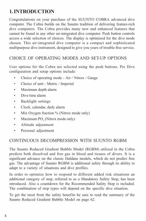
1. INTRODUCTION
Congratulations on your purchase of the SUUNTO COBRA advanced divecomputer. The Cobra builds on the Suunto tradition of delivering feature-richdive computers. The Cobra provides many new and enhanced features thatcannot be found in any other air-integrated dive computer. Push button controlsaccess a wide selection of choices. The display is optimized for the dive modechosen. This air-integrated dive computer is a compact and sophisticatedmultipurpose dive instrument, designed to give you years of trouble-free service.
CHOICE OF OPERATING MODES AND SET-UP OPTIONS
User options for the Cobra are selected using the push buttons. Pre Diveconfiguration and setup options include:
• Choice of operating mode - Air / Nitrox / Gauge
• Choice of unit - Metric / Imperial
• Maximum depth alarm
• Dive time alarm
• Backlight settings
• Clock, calendar, daily alarm
• Mix Oxygen fraction % (Nitrox mode only)
• Maximum PO2 (Nitrox mode only)
• Altitude adjustment
• Personal adjustment
CONTINUOUS DECOMPRESSION WITH SUUNTO RGBM
The Suunto Reduced Gradient Bubble Model (RGBM) utilized in the Cobrapredicts both dissolved and free gas in blood and tissues of divers. It is asignificant advance on the classic Haldane models, which do not predict freegas. The advantage of Suunto RGBM is additional safety through its ability toadapt to a variety of situations and dive profiles.
In order to optimize how to respond to different added risk situations anadditional category of stop, referred to as a Mandatory Safety Stop, has beenintroduced. Also a countdown for the Recommended Safety Stop is included.The combination of stop types will depend on the specific dive situation.
To get the most from the safety benefits be sure to read the summary of theSuunto Reduced Gradient Bubble Model on page 62.
9
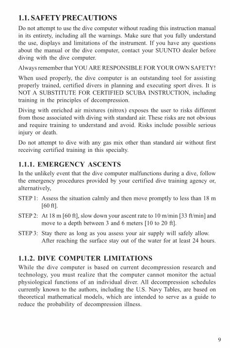
1.1. SAFETY PRECAUTIONSDo not attempt to use the dive computer without reading this instruction manualin its entirety, including all the warnings. Make sure that you fully understandthe use, displays and limitations of the instrument. If you have any questionsabout the manual or the dive computer, contact your SUUNTO dealer beforediving with the dive computer.
Always remember that YOU ARE RESPONSIBLE FOR YOUR OWN SAFETY!
When used properly, the dive computer is an outstanding tool for assistingproperly trained, certified divers in planning and executing sport dives. It isNOT A SUBSTITUTE FOR CERTIFIED SCUBA INSTRUCTION, includingtraining in the principles of decompression.
Diving with enriched air mixtures (nitrox) exposes the user to risks differentfrom those associated with diving with standard air. These risks are not obviousand require training to understand and avoid. Risks include possible seriousinjury or death.
Do not attempt to dive with any gas mix other than standard air without firstreceiving certified training in this specialty.
1.1.1. EMERGENCY ASCENTSIn the unlikely event that the dive computer malfunctions during a dive, followthe emergency procedures provided by your certified dive training agency or,alternatively,
STEP 1: Assess the situation calmly and then move promptly to less than 18 m[60 ft].
STEP 2: At 18 m [60 ft], slow down your ascent rate to 10 m/min [33 ft/min] andmove to a depth between 3 and 6 meters [10 to 20 ft].
STEP 3: Stay there as long as you assess your air supply will safely allow.After reaching the surface stay out of the water for at least 24 hours.
1.1.2. DIVE COMPUTER LIMITATIONSWhile the dive computer is based on current decompression research andtechnology, you must realize that the computer cannot monitor the actualphysiological functions of an individual diver. All decompression schedulescurrently known to the authors, including the U.S. Navy Tables, are based ontheoretical mathematical models, which are intended to serve as a guide toreduce the probability of decompression illness.
10
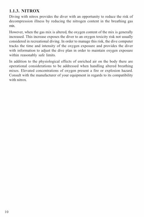
1.1.3. NITROXDiving with nitrox provides the diver with an opportunity to reduce the risk ofdecompression illness by reducing the nitrogen content in the breathing gasmix.
However, when the gas mix is altered, the oxygen content of the mix is generallyincreased. This increase exposes the diver to an oxygen toxicity risk not usuallyconsidered in recreational diving. In order to manage this risk, the dive computertracks the time and intensity of the oxygen exposure and provides the diverwith information to adjust the dive plan in order to maintain oxygen exposurewithin reasonably safe limits.
In addition to the physiological effects of enriched air on the body there areoperational considerations to be addressed when handling altered breathingmixes. Elevated concentrations of oxygen present a fire or explosion hazard.Consult with the manufacturer of your equipment in regards to its compatibilitywith nitrox.
11
2. GETTING ACQUAINTED
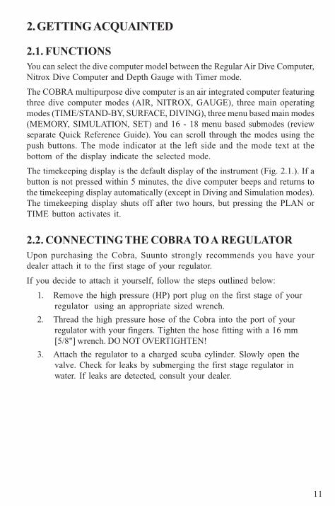
2.1. FUNCTIONSYou can select the dive computer model between the Regular Air Dive Computer,Nitrox Dive Computer and Depth Gauge with Timer mode.
The COBRA multipurpose dive computer is an air integrated computer featuringthree dive computer modes (AIR, NITROX, GAUGE), three main operatingmodes (TIME/STAND-BY, SURFACE, DIVING), three menu based main modes(MEMORY, SIMULATION, SET) and 16 - 18 menu based submodes (reviewseparate Quick Reference Guide). You can scroll through the modes using thepush buttons. The mode indicator at the left side and the mode text at thebottom of the display indicate the selected mode.
The timekeeping display is the default display of the instrument (Fig. 2.1.). If abutton is not pressed within 5 minutes, the dive computer beeps and returns tothe timekeeping display automatically (except in Diving and Simulation modes).The timekeeping display shuts off after two hours, but pressing the PLAN orTIME button activates it.
2.2. CONNECTING THE COBRA TO A REGULATORUpon purchasing the Cobra, Suunto strongly recommends you have yourdealer attach it to the first stage of your regulator.
If you decide to attach it yourself, follow the steps outlined below:
1. Remove the high pressure (HP) port plug on the first stage of yourregulator using an appropriate sized wrench.
2. Thread the high pressure hose of the Cobra into the port of yourregulator with your fingers. Tighten the hose fitting with a 16 mm[5/8"] wrench. DO NOT OVERTIGHTEN!
3. Attach the regulator to a charged scuba cylinder. Slowly open thevalve. Check for leaks by submerging the first stage regulator inwater. If leaks are detected, consult your dealer.
12
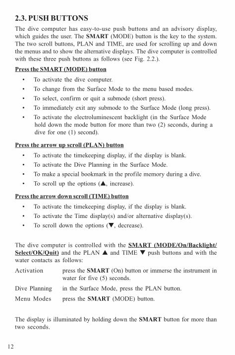
2.3. PUSH BUTTONSThe dive computer has easy-to-use push buttons and an advisory display,which guides the user. The SMART (MODE) button is the key to the system.The two scroll buttons, PLAN and TIME, are used for scrolling up and downthe menus and to show the alternative displays. The dive computer is controlledwith these three push buttons as follows (see Fig. 2.2.).
Press the SMART (MODE) button
• To activate the dive computer.
• To change from the Surface Mode to the menu based modes.
• To select, confirm or quit a submode (short press).
• To immediately exit any submode to the Surface Mode (long press).
• To activate the electroluminescent backlight (in the Surface Modehold down the mode button for more than two (2) seconds, during adive for one (1) second).
Press the arrow up scroll (PLAN) button
• To activate the timekeeping display, if the display is blank.
• To activate the Dive Planning in the Surface Mode.
• To make a special bookmark in the profile memory during a dive.
• To scroll up the options (�, increase).
Press the arrow down scroll (TIME) button
• To activate the timekeeping display, if the display is blank.
• To activate the Time display(s) and/or alternative display(s).
• To scroll down the options (�, decrease).
The dive computer is controlled with the SMART (MODE/On/Backlight/Select/OK/Quit) and the PLAN � and TIME � push buttons and with thewater contacts as follows:
Activation press the SMART (On) button or immerse the instrument inwater for five (5) seconds.
Dive Planning in the Surface Mode, press the PLAN button.
Menu Modes press the SMART (MODE) button.
The display is illuminated by holding down the SMART button for more thantwo seconds.
13
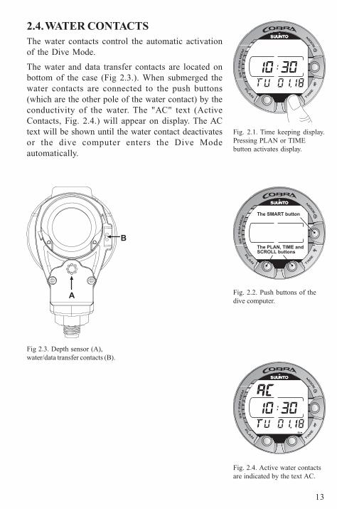
2.4. WATER CONTACTSThe water contacts control the automatic activationof the Dive Mode.
The water and data transfer contacts are located onbottom of the case (Fig 2.3.). When submerged thewater contacts are connected to the push buttons(which are the other pole of the water contact) by theconductivity of the water. The "AC" text (ActiveContacts, Fig. 2.4.) will appear on display. The ACtext will be shown until the water contact deactivatesor the dive computer enters the Dive Modeautomatically.
Fig. 2.1. Time keeping display.Pressing PLAN or TIMEbutton activates display.
Fig. 2.2. Push buttons of thedive computer.
Fig 2.3. Depth sensor (A),water/data transfer contacts (B).
Fig. 2.4. Active water contactsare indicated by the text AC.
A
B
The SMART button
The PLAN, TIME andSCROLL buttons
14
°F°C
ft
MAXAVGPO2
NO DEC TIME
STOP
TIME
TIME
SURF
DIVE
O2% ASC TIME
CEILING
OK
QUIT
SELECT
OPTIONS
NO
SLOW
T
CB
OLF
DIVE
m
psi
AIR
bar
3. DIVING WITH THE COBRA
This section contains instructions on how to operatethe dive computer and interpret its displays. You willfind that this dive computer is easy to use and read.Each display shows only the data relevant to thatspecific diving situation.
3.1 BEFORE DIVING
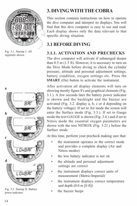
3.1.1. ACTIVATION AND PRECHECKSThe dive computer will activate if submerged deeperthan 0.5 m (1.5 ft). However, it is necessary to turn onthe Dive Mode before diving to check the cylinderpressure, altitude and personal adjustment settings,battery condition, oxygen settings etc. Press theSMART (On) button to activate the instrument.
After activation all display elements will turn onshowing mostly figure 8's and graphical elements (Fig.3.1.). A few seconds later the battery power indicatoris shown and the backlight and the buzzer areactivated (Fig. 3.2. display a, b, c or d depending onthe battery voltage). If set to Air mode the screen willenter the Surface mode (Fig. 3.3.). If set to Gaugemode the text GAUGE is shown (Fig. 3.4.) and if set toNitrox mode the essential oxygen parameters areshown with the text NITROX (Fig. 3.21.) before theSurface mode.
At this time, perform your precheck making sure that:
• the instrument operates in the correct modeand provides a complete display (Air andNitrox modes)
• the low battery indicator is not on
• the altitude and personal adjustmentsettings are correct
• the instrument displays correct units ofmeasurement (Metric/Imperial)
• the instrument displays correct temperatureand depth (0.0 m [0 ft])
• the buzzer beeps
Fig. 3.1. Startup I. Allsegments shown.
Fig. 3.2. Startup II. Batterypower indicator.
QUIT
OK
a
b
c
d
15
• you have enough air for your planned dive. You should also checkthe pressure reading against your back-up pressure gauge.
And if set to Nitrox mode, make sure that:
• the oxygen percentage is adjusted according to the measured Nitroxblend in your cylinder
• the oxygen partial pressure limit is set correctly.
The dive computer is now ready for diving.
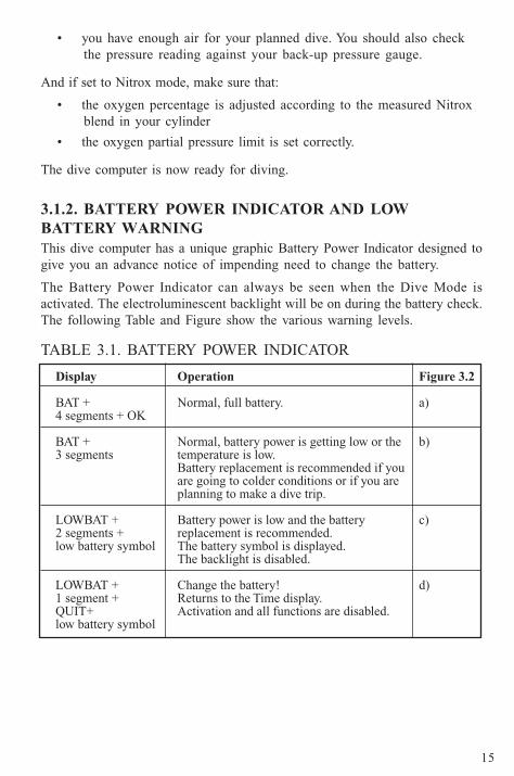
3.1.2. BATTERY POWER INDICATOR AND LOWBATTERY WARNINGThis dive computer has a unique graphic Battery Power Indicator designed togive you an advance notice of impending need to change the battery.
The Battery Power Indicator can always be seen when the Dive Mode isactivated. The electroluminescent backlight will be on during the battery check.The following Table and Figure show the various warning levels.
TABLE 3.1. BATTERY POWER INDICATOR
16
TIMEDIVE
m
bar
TIMEDIVE
m
TIME
bar
°C
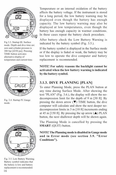
Fig 3.3. Startup III. Surfacemode. Depth and dive time arezero and cylinder pressure is300 bar [4350 psi]. PressingTIME button activatesalternative display oftemperature and current time.
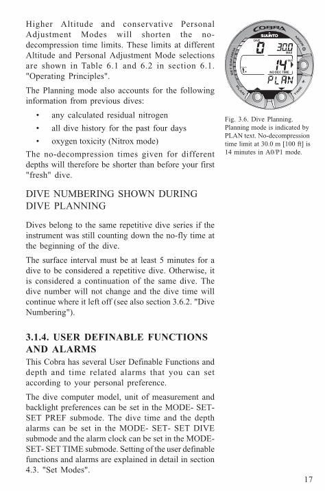
Fig. 3.4. Startup IV. Gaugemode.
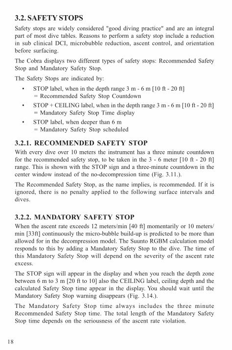
Fig. 3.5. Low Battery Warning.Battery symbol indicates thatthe battery is low and batteryreplacement is recommended.
Temperature or an internal oxidation of the batteryaffects the battery voltage. If the instrument is storedfor a long period, the low battery warning may bedisplayed even though the battery has enoughcapacity. The low battery warning may also bedisplayed at low temperatures, even though thebattery has enough capacity in warmer conditions.In these cases repeat the battery check procedure.
After battery check the Low Battery Warning isindicated by the battery symbol (Fig. 3.5.).
If the battery symbol is displayed in the Surface modeor if the display is faded or weak, the battery may betoo low to operate the dive computer and batteryreplacement is recommended.
NOTE! For safety reasons the backlight cannot beactivated when the low battery warning is indicatedby the battery symbol.
3.1.3. DIVE PLANNING [PLAN]To enter Planning Mode, press the PLAN button atany time during Surface Mode. After showing thetext "PLAN" (Fig. 3.6.), the display will show the no-decompression limit for the depth of 9 m [30 ft]. Bypressing the down arrow (�) TIME button, the divecomputer will calculate and show the next deeper no-decompression limits in 3 m [10 ft] increments endingat 45 m [150 ft]. By pressing the up arrow (�) PLANbutton, the next shallower depth will be shown again.
The Planning Mode is cancelled by pressing theSMART (QUIT) button.
NOTE! The Planning mode is disabled in Gauge modeand in Error mode (see section 3.9. "ErrorConditions").
17
QUIT
DIVE
NO DEC TIME
MAX
Higher Altitude and conservative PersonalAdjustment Modes will shorten the no-decompression time limits. These limits at differentAltitude and Personal Adjustment Mode selectionsare shown in Table 6.1 and 6.2 in section 6.1."Operating Principles".
The Planning mode also accounts for the followinginformation from previous dives:
• any calculated residual nitrogen
• all dive history for the past four days
• oxygen toxicity (Nitrox mode)
The no-decompression times given for differentdepths will therefore be shorter than before your first"fresh" dive.
DIVE NUMBERING SHOWN DURINGDIVE PLANNING
Dives belong to the same repetitive dive series if theinstrument was still counting down the no-fly time atthe beginning of the dive.
The surface interval must be at least 5 minutes for adive to be considered a repetitive dive. Otherwise, itis considered a continuation of the same dive. Thedive number will not change and the dive time willcontinue where it left off (see also section 3.6.2. "DiveNumbering").
3.1.4. USER DEFINABLE FUNCTIONSAND ALARMSThis Cobra has several User Definable Functions anddepth and time related alarms that you can setaccording to your personal preference.
The dive computer model, unit of measurement andbacklight preferences can be set in the MODE- SET-SET PREF submode. The dive time and the depthalarms can be set in the MODE- SET- SET DIVEsubmode and the alarm clock can be set in the MODE-SET- SET TIME submode. Setting of the user definablefunctions and alarms are explained in detail in section4.3. "Set Modes".
Fig. 3.6. Dive Planning.Planning mode is indicated byPLAN text. No-decompressiontime limit at 30.0 m [100 ft] is14 minutes in A0/P1 mode.
18
3.2. SAFETY STOPSSafety stops are widely considered "good diving practice" and are an integralpart of most dive tables. Reasons to perform a safety stop include a reductionin sub clinical DCI, microbubble reduction, ascent control, and orientationbefore surfacing.
The Cobra displays two different types of safety stops: Recommended SafetyStop and Mandatory Safety Stop.
The Safety Stops are indicated by:
• STOP label, when in the depth range 3 m - 6 m [10 ft - 20 ft]= Recommended Safety Stop Countdown
• STOP + CEILING label, when in the depth range 3 m - 6 m [10 ft - 20 ft]= Mandatory Safety Stop Time display
• STOP label, when deeper than 6 m= Mandatory Safety Stop scheduled
3.2.1. RECOMMENDED SAFETY STOPWith every dive over 10 meters the instrument has a three minute countdownfor the recommended safety stop, to be taken in the 3 - 6 meter [10 ft - 20 ft]range. This is shown with the STOP sign and a three-minute countdown in thecenter window instead of the no-decompression time (Fig. 3.11.).
The Recommended Safety Stop, as the name implies, is recommended. If it isignored, there is no penalty applied to the following surface intervals anddives.
3.2.2. MANDATORY SAFETY STOPWhen the ascent rate exceeds 12 meters/min [40 ft] momentarily or 10 meters/min [33ft] continuously the micro-bubble build-up is predicted to be more thanallowed for in the decompression model. The Suunto RGBM calculation modelresponds to this by adding a Mandatory Safety Stop to the dive. The time ofthis Mandatory Safety Stop will depend on the severity of the ascent rateexcess.
The STOP sign will appear in the display and when you reach the depth zonebetween 6 m to 3 m [20 ft to 10] also the CEILING label, ceiling depth and thecalculated Safety Stop time appear in the display. You should wait until theMandatory Safety Stop warning disappears (Fig. 3.14.).
The Mandatory Safety Stop time always includes the three minuteRecommended Safety Stop time. The total length of the Mandatory SafetyStop time depends on the seriousness of the ascent rate violation.
19
You must not ascend shallower than 3 m [10 ft] with the Mandatory Safety Stopwarning on. If you ascend above the Mandatory Safety Stop ceiling, a downwardpointing arrow will appear and a continuous beeping starts (Fig. 3.15.). Youshould immediately descend to, or below, the Mandatory Safety Stop ceilingdepth. If you correct this situation at any time during that dive, there are noaffects on the decompression calculations for future dives.
If you continue to violate the Mandatory Safety Stop, the tissue calculationmodel is affected and the dive computer shortens the available no-decompression time for your next dive. In this situation, it is recommended toprolong your surface interval time before your next dive.
20
m
NO DEC TIME
T
CB
MAX
DIVE TIME
MAX
bar
AIR TIME
3.3. DIVING IN AIR MODE
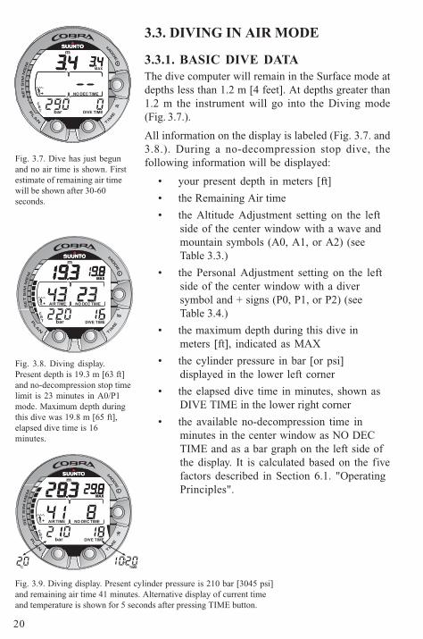
3.3.1. BASIC DIVE DATAThe dive computer will remain in the Surface mode atdepths less than 1.2 m [4 feet]. At depths greater than1.2 m the instrument will go into the Diving mode(Fig. 3.7.).
All information on the display is labeled (Fig. 3.7. and3.8.). During a no-decompression stop dive, thefollowing information will be displayed:
• your present depth in meters [ft]
• the Remaining Air time
• the Altitude Adjustment setting on the leftside of the center window with a wave andmountain symbols (A0, A1, or A2) (seeTable 3.3.)
• the Personal Adjustment setting on the leftside of the center window with a diversymbol and + signs (P0, P1, or P2) (seeTable 3.4.)
• the maximum depth during this dive inmeters [ft], indicated as MAX
• the cylinder pressure in bar [or psi]displayed in the lower left corner
• the elapsed dive time in minutes, shown asDIVE TIME in the lower right corner
• the available no-decompression time inminutes in the center window as NO DECTIME and as a bar graph on the left side ofthe display. It is calculated based on the fivefactors described in Section 6.1. "OperatingPrinciples".
Fig. 3.9. Diving display. Present cylinder pressure is 210 bar [3045 psi]and remaining air time 41 minutes. Alternative display of current timeand temperature is shown for 5 seconds after pressing TIME button.
Fig. 3.7. Dive has just begunand no air time is shown. Firstestimate of remaining air timewill be shown after 30-60seconds.
Fig. 3.8. Diving display.Present depth is 19.3 m [63 ft]and no-decompression stop timelimit is 23 minutes in A0/P1mode. Maximum depth duringthis dive was 19.8 m [65 ft],elapsed dive time is 16minutes.
TIMEDIVE
m
NO DEC TIME
T
CB
MAX
bar
m
NO DEC TIME
T
CB
MAX
DIVE TIME
MAX
bar
AIR TIME
TIME°C
21
DIVE TIMET
CB
m
STOP
MAX
AIR TIME
bar
m
NO DEC TIME
T
CB
MAX
DIVE TIME
AIR TIME
bar
m
NO DEC TIME
T
CB
MAX
DIVE TIMEbar
AIR TIME
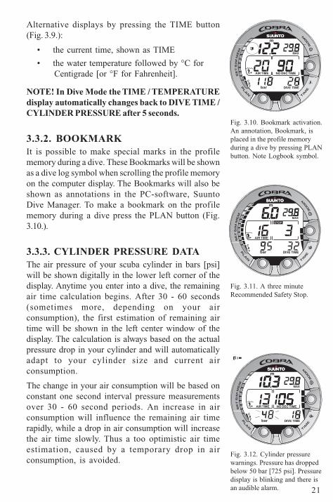
Alternative displays by pressing the TIME button(Fig. 3.9.):
• the current time, shown as TIME
• the water temperature followed by °C forCentigrade [or °F for Fahrenheit].
NOTE! In Dive Mode the TIME / TEMPERATUREdisplay automatically changes back to DIVE TIME /CYLINDER PRESSURE after 5 seconds.
3.3.2. BOOKMARKIt is possible to make special marks in the profilememory during a dive. These Bookmarks will be shownas a dive log symbol when scrolling the profile memoryon the computer display. The Bookmarks will also beshown as annotations in the PC-software, SuuntoDive Manager. To make a bookmark on the profilememory during a dive press the PLAN button (Fig.3.10.).
3.3.3. CYLINDER PRESSURE DATAThe air pressure of your scuba cylinder in bars [psi]will be shown digitally in the lower left corner of thedisplay. Anytime you enter into a dive, the remainingair time calculation begins. After 30 - 60 seconds(sometimes more, depending on your airconsumption), the first estimation of remaining airtime will be shown in the left center window of thedisplay. The calculation is always based on the actualpressure drop in your cylinder and will automaticallyadapt to your cylinder size and current airconsumption.
The change in your air consumption will be based onconstant one second interval pressure measurementsover 30 - 60 second periods. An increase in airconsumption will influence the remaining air timerapidly, while a drop in air consumption will increasethe air time slowly. Thus a too optimistic air timeestimation, caused by a temporary drop in airconsumption, is avoided.
Fig. 3.10. Bookmark activation.An annotation, Bookmark, isplaced in the profile memoryduring a dive by pressing PLANbutton. Note Logbook symbol.
Fig. 3.12. Cylinder pressurewarnings. Pressure has droppedbelow 50 bar [725 psi]. Pressuredisplay is blinking and there isan audible alarm.
Fig. 3.11. A three minuteRecommended Safety Stop.
22
T
CB
m
STOP
CEILING
DIVE TIME
AIR TIME
bar
DIVE TIMET
CB
m CEILING
STOP
MAX
TIME
AIR TIME
bar
°C
DIVE TIMET
CB
m
MAX
SLOW
NO DEC TIME
STOP
AIR TIME
bar
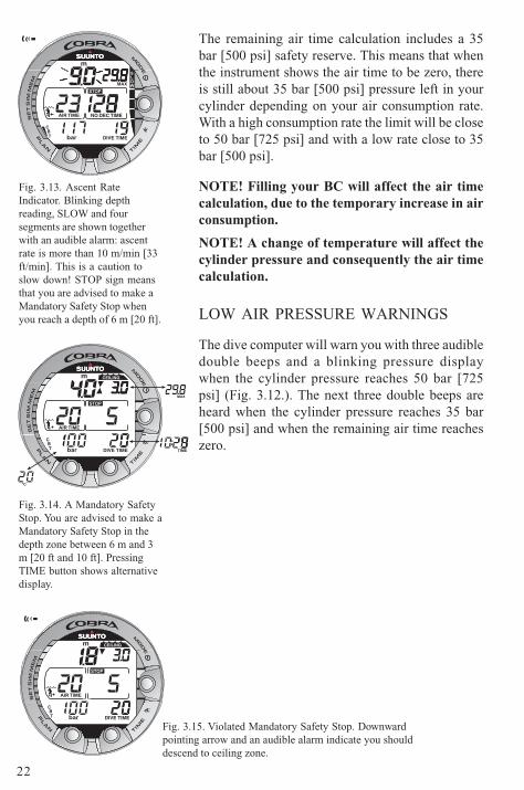
The remaining air time calculation includes a 35bar [500 psi] safety reserve. This means that whenthe instrument shows the air time to be zero, thereis still about 35 bar [500 psi] pressure left in yourcylinder depending on your air consumption rate.With a high consumption rate the limit will be closeto 50 bar [725 psi] and with a low rate close to 35bar [500 psi].
NOTE! Filling your BC will affect the air timecalculation, due to the temporary increase in airconsumption.
NOTE! A change of temperature will affect thecylinder pressure and consequently the air timecalculation.
LOW AIR PRESSURE WARNINGS
The dive computer will warn you with three audibledouble beeps and a blinking pressure displaywhen the cylinder pressure reaches 50 bar [725psi] (Fig. 3.12.). The next three double beeps areheard when the cylinder pressure reaches 35 bar[500 psi] and when the remaining air time reacheszero.
Fig. 3.13. Ascent RateIndicator. Blinking depthreading, SLOW and foursegments are shown togetherwith an audible alarm: ascentrate is more than 10 m/min [33ft/min]. This is a caution toslow down! STOP sign meansthat you are advised to make aMandatory Safety Stop whenyou reach a depth of 6 m [20 ft].
Fig. 3.14. A Mandatory SafetyStop. You are advised to make aMandatory Safety Stop in thedepth zone between 6 m and 3m [20 ft and 10 ft]. PressingTIME button shows alternativedisplay.
Fig. 3.15. Violated Mandatory Safety Stop. Downwardpointing arrow and an audible alarm indicate you shoulddescend to ceiling zone.
23
3.3.4. CONSUMED BOTTOM TIME (CBT)The available no-decompression stop time is also shown visually in the multi-function bar graph on the left side of the display (Fig. 3.7., 3.8. and 3.9.). Whenyour available no-decompression time decreases below 200 minutes, the first(lowest) bar graph segment appears. As your body absorbs more nitrogen,more segments start to appear.
Green Zone - As a safety precaution Suunto recommends you should maintainthe no-decompression bar graph within the green zone. Segments start toappear when the available no-decompression time decreases below 100, 80, 60,50, 40, 30 and 20 minutes.
Yellow Zone - As the bars reach the yellow zone, your no-decompression stoptime is less than 10 or 5 minutes and you are getting very close to no-decompression limits. At this point, you should start your ascent towards thesurface.
Red Zone - As all of the bars appear (red zone), your no-decompression stoptime has become zero and your dive has become a decompression stop dive(for more information see section 3.3.6. "Decompression dives").
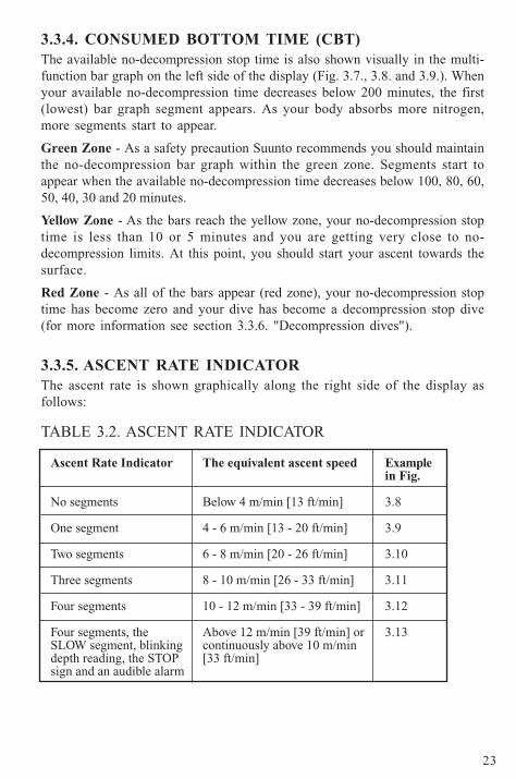
3.3.5. ASCENT RATE INDICATORThe ascent rate is shown graphically along the right side of the display asfollows:
TABLE 3.2. ASCENT RATE INDICATOR
24
When the maximum allowed ascent rate is exceeded, the fifth SLOW warningsegment and the STOP sign appear and the depth reading starts to blink,indicating that the maximum ascent rate has been exceeded continuously orthat the current ascent rate is significantly above the allowed rate.
Whenever the SLOW warning segment and the STOP sign appear (Fig. 3.13.),you should immediately slow down your ascent. When you reach the depthzone between 6 m to 3 m [20 ft to 10 ft] the STOP and CEILING depth labels willadvise you to make a Mandatory Safety Stop. Wait until the warning disappears(Fig. 3.14.). You should not ascend shallower than 3 m [10 ft] with the MandatorySafety Stop warning on.
WARNING!
DO NOT EXCEED THE MAXIMUM ASCENT RATE! Rapid ascents increasethe risk of injury. You should always make the Mandatory and RecommendedSafety Stops after you have exceeded the maximum recommended ascentrate. If this Mandatory Safety Stop is not completed the decompressionmodel will penalize your next dive(s).
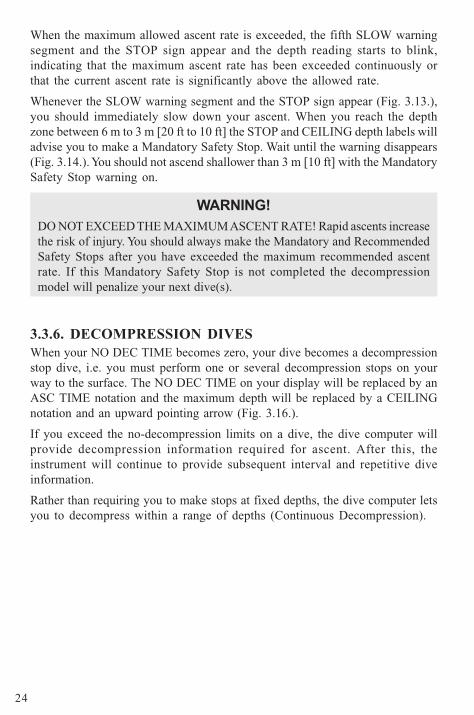
3.3.6. DECOMPRESSION DIVESWhen your NO DEC TIME becomes zero, your dive becomes a decompressionstop dive, i.e. you must perform one or several decompression stops on yourway to the surface. The NO DEC TIME on your display will be replaced by anASC TIME notation and the maximum depth will be replaced by a CEILINGnotation and an upward pointing arrow (Fig. 3.16.).
If you exceed the no-decompression limits on a dive, the dive computer willprovide decompression information required for ascent. After this, theinstrument will continue to provide subsequent interval and repetitive diveinformation.
Rather than requiring you to make stops at fixed depths, the dive computer letsyou to decompress within a range of depths (Continuous Decompression).
25
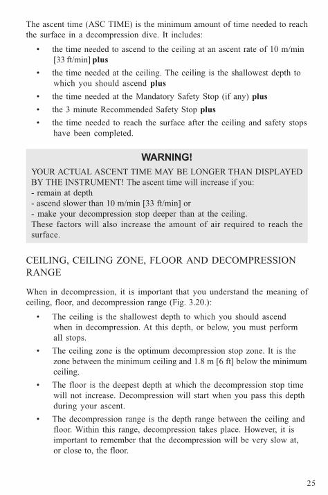
The ascent time (ASC TIME) is the minimum amount of time needed to reachthe surface in a decompression dive. It includes:
• the time needed to ascend to the ceiling at an ascent rate of 10 m/min[33 ft/min] plus
• the time needed at the ceiling. The ceiling is the shallowest depth towhich you should ascend plus
• the time needed at the Mandatory Safety Stop (if any) plus
• the 3 minute Recommended Safety Stop plus
• the time needed to reach the surface after the ceiling and safety stopshave been completed.
WARNING!
YOUR ACTUAL ASCENT TIME MAY BE LONGER THAN DISPLAYEDBY THE INSTRUMENT! The ascent time will increase if you:- remain at depth- ascend slower than 10 m/min [33 ft/min] or- make your decompression stop deeper than at the ceiling.These factors will also increase the amount of air required to reach thesurface.
CEILING, CEILING ZONE, FLOOR AND DECOMPRESSIONRANGE
When in decompression, it is important that you understand the meaning ofceiling, floor, and decompression range (Fig. 3.20.):
• The ceiling is the shallowest depth to which you should ascendwhen in decompression. At this depth, or below, you must performall stops.
• The ceiling zone is the optimum decompression stop zone. It is thezone between the minimum ceiling and 1.8 m [6 ft] below the minimumceiling.
• The floor is the deepest depth at which the decompression stop timewill not increase. Decompression will start when you pass this depthduring your ascent.
• The decompression range is the depth range between the ceiling andfloor. Within this range, decompression takes place. However, it isimportant to remember that the decompression will be very slow at,or close to, the floor.
26
DIVE TIMET
CB
m
STOP
CEILING
ASC TIME
MAX
TIME
AIR TIME
bar
°C
DIVE TIMET
CB
m CEILING
ASC TIME
AIR TIME
bar
DIVE TIMET
CB
m CEILING
ASC TIME
AIR TIME
bar
AIR TIMEAIR TIMEAIR TIMEAIR TIME
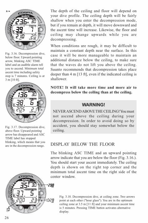
Fig. 3.16. Decompression dive,below floor. Upward pointingarrow, blinking ASC TIMElabel and an audible alarm tellyou to ascend. Minimum totalascent time including safetystop is 7 minutes. Ceiling is at3 m [10 ft].
Fig. 3.17. Decompression dive,above floor. Upward pointingarrow has disappeared and ASCTIME label has stoppedblinking, which means that youare in the decompression range.
Fig. 3.18. Decompression dive, at ceiling zone. Two arrowspoint at each other ("hour glass"). You are in the optimumceiling zone at 3.5 m [11 ft] and your minimum ascent timeis 5 minutes. Pressing TIME button activates alternativedisplay.
The depth of the ceiling and floor will depend onyour dive profile. The ceiling depth will be fairlyshallow when you enter the decompression mode,but if you remain at depth, it will move downward andthe ascent time will increase. Likewise, the floor andceiling may change upwards while you aredecompressing.
When conditions are rough, it may be difficult tomaintain a constant depth near the surface. In thiscase it will be more manageable to maintain anadditional distance below the ceiling, to make surethat the waves do not lift you above the ceiling.Suunto recommends that decompression takes placedeeper than 4 m [13 ft], even if the indicated ceiling isshallower.
NOTE! It will take more time and more air todecompress below the ceiling than at the ceiling.
WARNING!
NEVER ASCEND ABOVE THE CEILING! You mustnot ascend above the ceiling during yourdecompression. In order to avoid doing so byaccident, you should stay somewhat below theceiling.
DISPLAY BELOW THE FLOOR
The blinking ASC TIME and an upward pointingarrow indicate that you are below the floor (Fig. 3.16.).You should start your ascent immediately. The ceilingdepth is shown on the right top corner and theminimum total ascent time on the right side of thecenter window.
27
DIVE TIMET
CB
m
STOP
CEILING
ASC TIME
AIR TIME
bar
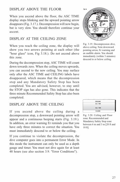
DISPLAY ABOVE THE FLOOR
When you ascend above the floor, the ASC TIMEdisplay stops blinking and the upward pointing arrowdisappears (Fig. 3.17.). Decompression will now begin,but is very slow. You should therefore continue yourascent.
DISPLAY AT THE CEILING ZONE
When you reach the ceiling zone, the display willshow you two arrows pointing at each other (the"hour glass" icon, Fig 3.18.). Do not ascend abovethis zone.
During the decompression stop, ASC TIME will countdown towards zero. When the ceiling moves upwards,you can ascend to the new ceiling. You may surfaceonly after the ASC TIME and CEILING labels havedisappeared, which means that the decompressionstop and any Mandatory Safety Stop has beencompleted. You are advised, however, to stay untilthe STOP sign has also gone. This indicates that thethree minute Recommended Safety Stop has also beencompleted.
DISPLAY ABOVE THE CEILING
If you ascend above the ceiling during adecompression stop, a downward pointing arrow willappear and a continuous beeping starts (Fig. 3.19.).In addition, an error warning Er reminds you that youhave only three minutes to correct the situation. Youmust immediately descend to or below the ceiling.
If you continue to violate the decompression, thedive computer goes into a permanent Error Mode. Inthis mode the instrument can only be used as a depthgauge and timer. You must not dive again for at least48 hours (see also section 3.9. "Error Conditions").
Fig. 3.19. Decompression dive,above ceiling. Note downwardpointing arrow, Er warning andan audible alarm. You shouldimmediately (within 3 minutes)descend to or below ceiling.
Fig. 3.20. Ceiling and Floorzone. Recommended andMandatory Safety Stop zonebetween 6 m and 3 m [20 ft and10 ft].
3m / 10ft
6m / 18ft
CEILING
FLOOR
28
TIMEDIVE
m
OLF
bar
MAX
O2%
NO DEC TIME
PO2
O2%
OLF
m
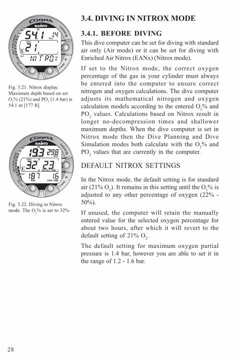
Fig. 3.21. Nitrox display.Maximum depth based on setO
2% (21%) and PO
2 (1.4 bar) is
54.1 m [177 ft].
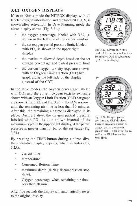
Fig. 3.22. Diving in Nitroxmode. The O
2% is set to 32%.
3.4. DIVING IN NITROX MODE
3.4.1. BEFORE DIVINGThis dive computer can be set for diving with standardair only (Air mode) or it can be set for diving withEnriched Air Nitrox (EANx) (Nitrox mode).
If set to the Nitrox mode, the correct oxygenpercentage of the gas in your cylinder must alwaysbe entered into the computer to ensure correctnitrogen and oxygen calculations. The dive computeradjusts its mathematical nitrogen and oxygencalculation models according to the entered O
2% and
PO2 values. Calculations based on Nitrox result in
longer no-decompression times and shallowermaximum depths. When the dive computer is set inNitrox mode then the Dive Planning and DiveSimulation modes both calculate with the O
2% and
PO2 values that are currently in the computer.
DEFAULT NITROX SETTINGS
In the Nitrox mode, the default setting is for standardair (21% O
2). It remains in this setting until the O
2% is
adjusted to any other percentage of oxygen (22% -50%).
If unused, the computer will retain the manuallyentered value for the selected oxygen percentage forabout two hours, after which it will revert to thedefault setting of 21% O
2.
The default setting for maximum oxygen partialpressure is 1.4 bar, however you are able to set it inthe range of 1.2 - 1.6 bar.
29
TIMEDIVE
O2%
m
NO DEC TIME
OLF
PO2
bar
NO DEC TIME
MAX
DIVE TIME
OLF
bar
AIR TIME
m
3.4.2. OXYGEN DISPLAYSIf set to Nitrox mode the NITROX display, with alllabeled oxygen information and the label NITROX, isshown after activation. In Dive Planning mode thenitrox display shows (Fig. 3.21.):
• the oxygen percentage, labeled with O2%, is
shown in the left side of the center window
• the set oxygen partial pressure limit, labeledwith PO
2, is shown in the upper right
display
• the maximum allowed depth based on the setoxygen percentage and partial pressure limit
• the current oxygen toxicity exposure shownwith an Oxygen Limit Fraction (OLF) bargraph along the left side of the display(instead of the CBT).
In the Dive modes, the oxygen percentage labeledwith O
2% and the current oxygen toxicity exposure
shown with an Oxygen Limit Fraction (OLF) bar graphare shown (Fig. 3.22. and Fig. 3.23.). The O
2% is shown
until the remaining air time is less than 30 minutes.After this, the remaining air time is displayed in itsplace. During a dive, the oxygen partial pressure,labeled with PO
2, is also shown instead of the
maximum depth in the upper right display, if the partialpressure is greater than 1.4 bar or the set value (Fig.3.24.).
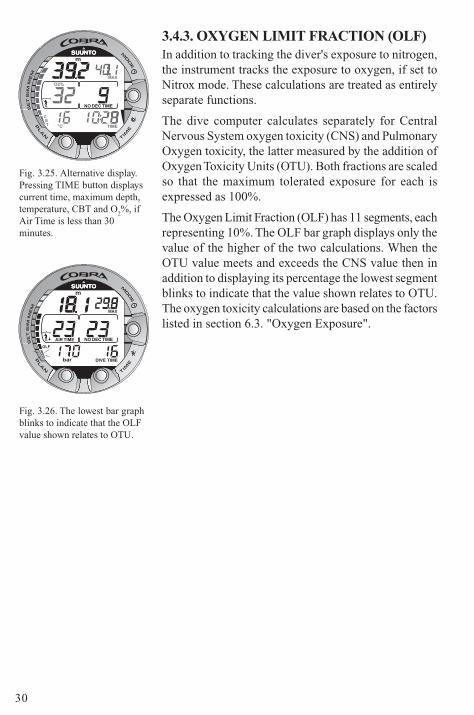
By pressing the TIME button during a nitrox dive,the alternative display appears, which includes (Fig.3.25.):
• current time
• temperature
• Consumed Bottom Time
• maximum depth (during decompression stopdive).
• Oxygen percentage when remaining air timeless than 30 min
After five seconds the display will automatically revertto the original display.
Fig. 3.23. Diving in Nitroxmode. After air time is less than30 minutes O
2% is substituted
by Air Time display.
Fig. 3.24. Oxygen partialpressure and OLF displays.There is an audible alarm asoxygen partial pressure isgreater than 1.4 bar or set value,and/or the OLF has reached80% limit.
30
3.4.3. OXYGEN LIMIT FRACTION (OLF)In addition to tracking the diver's exposure to nitrogen,the instrument tracks the exposure to oxygen, if set toNitrox mode. These calculations are treated as entirelyseparate functions.
The dive computer calculates separately for CentralNervous System oxygen toxicity (CNS) and PulmonaryOxygen toxicity, the latter measured by the addition ofOxygen Toxicity Units (OTU). Both fractions are scaledso that the maximum tolerated exposure for each isexpressed as 100%.
The Oxygen Limit Fraction (OLF) has 11 segments, eachrepresenting 10%. The OLF bar graph displays only thevalue of the higher of the two calculations. When theOTU value meets and exceeds the CNS value then inaddition to displaying its percentage the lowest segmentblinks to indicate that the value shown relates to OTU.The oxygen toxicity calculations are based on the factorslisted in section 6.3. "Oxygen Exposure".
Fig. 3.25. Alternative display.Pressing TIME button displayscurrent time, maximum depth,temperature, CBT and O
2%, if
Air Time is less than 30minutes.
Fig. 3.26. The lowest bar graphblinks to indicate that the OLFvalue shown relates to OTU.
°C TIME
O2%
m
NO DEC TIME
MAX
T
CB
NO DEC TIME
MAX
DIVE TIME
OLF
bar
AIR TIME
m
31
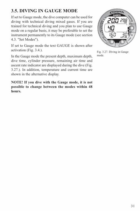
3.5. DIVING IN GAUGE MODEIf set to Gauge mode, the dive computer can be used fordiving with technical diving mixed gases. If you aretrained for technical diving and you plan to use Gaugemode on a regular basis, it may be preferable to set theinstrument permanently to its Gauge mode (see section4.3. "Set Modes").
If set to Gauge mode the text GAUGE is shown afteractivation (Fig. 3.4.).
In the Gauge mode the present depth, maximum depth,dive time, cylinder pressure, remaining air time andascent rate indicator are displayed during the dive (Fig.3.27.). In addition, temperature and current time areshown in the alternative display.
NOTE! If you dive with the Gauge mode, it is notpossible to change between the modes within 48hours.
Fig. 3.27. Diving in Gaugemode.
m
MAX
DIVE TIMEbar
AIR TIME
32
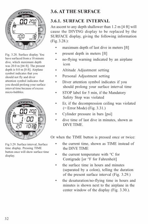
3.6. AT THE SURFACE
3.6.1. SURFACE INTERVALAn ascent to any depth shallower than 1.2 m [4 ft] willcause the DIVING display to be replaced by theSURFACE display, giving the following information(Fig. 3.28.):
• maximum depth of last dive in meters [ft]
• present depth in meters [ft]
• no-flying warning indicated by an airplaneicon
• Altitude Adjustment setting
• Personal Adjustment setting
• Diver attention symbol indicates if youshould prolong your surface interval time
• STOP label for 5 min, if the MandatorySafety Stop was violated
• Er, if the decompression ceiling was violated(= Error Mode) (Fig. 3.31.)
• Cylinder pressure in bars [psi]
• dive time of last dive in minutes, shown asDIVE TIME.
Or when the TIME button is pressed once or twice:
• the current time, shown as TIME instead ofthe DIVE TIME
• the current temperature with °C forCentigrade [or °F for Fahrenheit]
• the surface time in hours and minutes(separated by a colon), telling the durationof the present surface interval (Fig. 3.29.)
• the desaturation/no-flying time in hours andminutes is shown next to the airplane in thecenter window of the display (Fig. 3.30.).
Fig. 3.28. Surface display. Youhave surfaced from a 18 minutedive, which maximum depthwas 20.0 m [66 ft]. The presentdepth is 0.0 m [0 ft]. Airplanesymbol indicates that youshould not fly and diverattention symbol indicates thatyou should prolong your surfaceinterval time because of excessmicro-bubbles.
Fig 3.29. Surface interval, Surfacetime display. Pressing TIMEbutton once will show surface timedisplay.
MAX
TIMEDIVE
m
NO
bar
TIME
SURF
MAX
°C TIME
m
NO
33
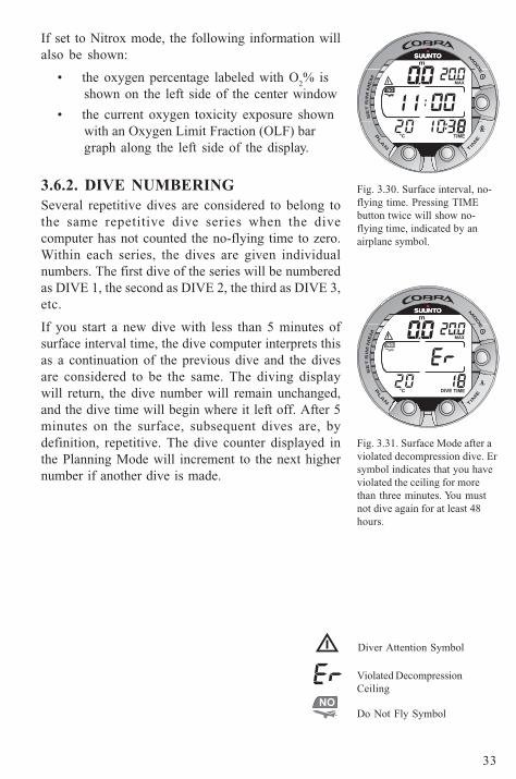
If set to Nitrox mode, the following information willalso be shown:
• the oxygen percentage labeled with O2% is
shown on the left side of the center window
• the current oxygen toxicity exposure shownwith an Oxygen Limit Fraction (OLF) bargraph along the left side of the display.
3.6.2. DIVE NUMBERINGSeveral repetitive dives are considered to belong tothe same repetitive dive series when the divecomputer has not counted the no-flying time to zero.Within each series, the dives are given individualnumbers. The first dive of the series will be numberedas DIVE 1, the second as DIVE 2, the third as DIVE 3,etc.
If you start a new dive with less than 5 minutes ofsurface interval time, the dive computer interprets thisas a continuation of the previous dive and the divesare considered to be the same. The diving displaywill return, the dive number will remain unchanged,and the dive time will begin where it left off. After 5minutes on the surface, subsequent dives are, bydefinition, repetitive. The dive counter displayed inthe Planning Mode will increment to the next highernumber if another dive is made.
Fig. 3.30. Surface interval, no-flying time. Pressing TIMEbutton twice will show no-flying time, indicated by anairplane symbol.
Fig. 3.31. Surface Mode after aviolated decompression dive. Ersymbol indicates that you haveviolated the ceiling for morethan three minutes. You mustnot dive again for at least 48hours.
Diver Attention Symbol
Violated DecompressionCeiling
Do Not Fly Symbol
MAX
°C TIME
NO
m
MAX
°C TIMEDIVE
m
NO
NO
NO
34
3.6.3. FLYING AFTER DIVINGThe no-flying time is shown in the center window next to the airplane image.Flying or travelling to a higher altitude should be avoided at any time thecomputer counts down the no-flying time.
NOTE! The airplane symbol is not shown on the stand-by display. You shouldalways activate the dive computer and check that the airplane symbol is notdisplayed prior to flying.
The no-flying time is always at least 12 hours or equivalent to the so-calleddesaturation time (if longer than 12 hours).
In the permanent Error mode and Gauge mode the no-flying time is 48 hours.
Divers Alert Network (DAN) recommends the following on no-flying times:
• A minimum surface interval of 12 hours would be required in order tobe reasonably assured a diver will remain symptom free upon ascentto altitude in a commercial jetliner (altitude up to 2400 m [8000 ft]).
• Divers who plan to make daily, multiple dives for several days, ormake dives that require decompression stops, should take specialprecautions and wait for an extended interval beyond 12 hoursbefore flight. Further, the Undersea and Hyperbaric Medical Society(UHMS) suggests divers using standard air tanks and exhibiting nosymptoms of decompression illness wait 24 hours after their last diveto fly in an aircraft with cabin pressure up to 2400 m [8000 ft]. Theonly two exceptions to this recommendation are:
• If a diver had less than 2 hours total accumulated dive time in the last48 hours, then a 12 hour surface interval before flying isrecommended.
• Following any dive that required a decompression stop, flying shouldbe delayed for at least 24 hours, and if possible, for 48 hours.
• Suunto recommends that flying is avoided until all the DAN andUHMS guidelines and the dive computer wait to fly conditions aresatisfied.
35
3.7. AUDIBLE AND VISUAL ALARMSThe dive computer features audible and visual alarms to advise when importantlimits are approached or to acknowledge preset alarms.
A short single beep occurs, when:
• the dive computer is activated.
• when the dive computer automatically returns to the TIME mode.
Three double beeps occur, when:
• the cylinder pressure reaches 50 bar [725 psi]. The cylinder pressuredisplay will start to blink (Fig. 3.12.).
• the cylinder pressure reaches 35 bar [500 psi].
• the calculated remaining air time reaches zero.
Three single beeps with a two second interval and the backlight activated for5 seconds occur, when:
• the no-decompression dive turns into a decompression stop dive. Anarrow pointing upwards and the blinking ascent warning ASC TIMEwill appear (Fig. 3.16.).
Continuous beeps and the backlight activated for 5 seconds occur, when:
• the maximum allowed ascent rate, 10 m/min [33 ft/min], is exceeded.SLOW and STOP warnings will appear (Fig. 3.13.).
• the Mandatory Safety Stop ceiling is exceeded. A downward pointingarrow will appear (Fig. 3.15.).
• the decompression ceiling depth is exceeded. An error warning Erand a downward pointing arrow appear. You should immediatelydescend to, or below, the ceiling. The instrument will otherwise entera permanent Error Mode within three minutes, indicated by apermanent Er (Fig. 3.19.).
36
You are able to preset alarms before the actual dive. The user programmablealarms can be set for maximum depth, dive time and time. The alarms activatewhen:
• The preset maximum depth is reached
- continuous beep series for 24 seconds or until any button is pressed.
- the maximum depth blinks as long as the present depth value exceeds the adjusted value.
• The preset dive time is reached
- continuous beep series for 24 seconds or until any button is pressed.
- the dive time blinks for one minute, if no button is pressed.
• The preset alarm time is reached
- the current time is shown.
- continuous beep series for 24 seconds or until any button is pressed.
- the current time blinks for one minute, if no button is pressed.
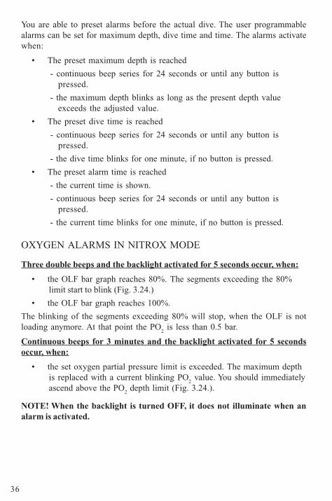
OXYGEN ALARMS IN NITROX MODE
Three double beeps and the backlight activated for 5 seconds occur, when:
• the OLF bar graph reaches 80%. The segments exceeding the 80%limit start to blink (Fig. 3.24.)
• the OLF bar graph reaches 100%.
The blinking of the segments exceeding 80% will stop, when the OLF is notloading anymore. At that point the PO
2 is less than 0.5 bar.
Continuous beeps for 3 minutes and the backlight activated for 5 secondsoccur, when:
• the set oxygen partial pressure limit is exceeded. The maximum depthis replaced with a current blinking PO
2 value. You should immediately
ascend above the PO2 depth limit (Fig. 3.24.).
NOTE! When the backlight is turned OFF, it does not illuminate when analarm is activated.
37
WARNING!
WHEN THE OXYGEN LIMIT FRACTION INDICATES THAT THEMAXIMUM LIMIT IS REACHED, YOU MUST IMMEDIATELY ASCENDUNTIL THE WARNING STOPS BLINKING! Failure to take action to reduceoxygen exposure after the warning is given can rapidly increase the risk ofoxygen toxicity and the risk of injury or death.
3.8. HIGH ALTITUDE DIVES AND PERSONALADJUSTMENTThe dive computer can be adjusted both for diving at altitude and also toincrease the conservatism of the mathematical nitrogen model.
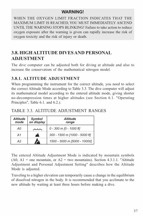
3.8.1. ALTITUDE ADJUSTMENTWhen programming the instrument for the correct altitude, you need to selectthe correct Altitude Mode according to Table 3.3. The dive computer will adjustits mathematical model according to the entered altitude mode, giving shorterno-decompression times at higher altitudes (see Section 6.1. "OperatingPrinciples", Table 6.1. and 6.2.).
TABLE 3.3. ALTITUDE ADJUSTMENT RANGES
The entered Altitude Adjustment Mode is indicated by mountain symbols(A0, A1 = one mountain, or A2 = two mountains). Section 4.3.1.1. "AltitudeAdjustment and Personal Adjustment Setting" describes how the AltitudeMode is adjusted.
Traveling to a higher elevation can temporarily cause a change in the equilibriumof dissolved nitrogen in the body. It is recommended that you acclimate to thenew altitude by waiting at least three hours before making a dive.
38
3.8.2. PERSONAL ADJUSTMENTThere are adverse personal factors for DCI which divers can predict in advanceand input into the decompression model. Factors that may affect susceptibilityto decompression illness vary between divers and also for the same diver fromone day to another. The three-step Personal Adjustment Mode is available, ifa more conservative dive plan is desired.
The personal factors which tend to increase the possibility of DCI include, butare not limited to:
• cold exposure - water temperature less than 20 °C [68 °F]
• the diver is below average physical fitness level
• diver fatigue
• diver dehydration
• previous history of DCI
• stress
• obesity
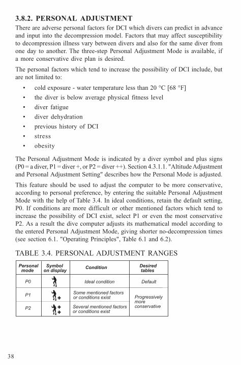
The Personal Adjustment Mode is indicated by a diver symbol and plus signs(P0 = a diver, P1 = diver +, or P2 = diver ++). Section 4.3.1.1. "Altitude Adjustmentand Personal Adjustment Setting" describes how the Personal Mode is adjusted.
This feature should be used to adjust the computer to be more conservative,according to personal preference, by entering the suitable Personal AdjustmentMode with the help of Table 3.4. In ideal conditions, retain the default setting,P0. If conditions are more difficult or other mentioned factors which tend toincrease the possibility of DCI exist, select P1 or even the most conservativeP2. As a result the dive computer adjusts its mathematical model according tothe entered Personal Adjustment Mode, giving shorter no-decompression times(see section 6.1. "Operating Principles", Table 6.1 and 6.2).
TABLE 3.4. PERSONAL ADJUSTMENT RANGES
39
3.9. ERROR CONDITIONSThe dive computer has warning indicators that alert the user to react to certainsituations that would significantly increased risk thew of DCI. If you do notrespond to its warnings, the dive computer will enter an Error Mode, indicatingthat the risk of DCI has greatly increased. If you understand and operate thedive computer sensibly, it is very unlikely you will ever put the instrument intothe Error Mode.
OMITTED DECOMPRESSION
The Error Mode results from omitted decompression, i.e. when you stay abovethe ceiling for more than three minutes. During this three-minute period the Erwarning is shown and the audible alarm beeps. After this, the dive computerwill enter a permanent Error Mode. The instrument will continue to functionnormally if you descend below the ceiling within this three-minute period.
Once in the permanent Error Mode only the ER warning is shown in the centerwindow. The dive computer will not show times for ascent or stops. However,all the other displays will function as before to provide information for ascent.You should immediately ascend to a depth of 3 to 6 m [10 to 20 ft] and remain atthis depth until air supply limitations require you to surface.
After surfacing, you should not dive for a minimum of 48 hours. During thepermanent Error Mode, the Er text will be displayed in the center window andthe Planning Mode will be disabled.
40
4. MENU BASED MODES
To make yourself familiar with the menu basedfunctions, please use your Quick Reference Guidesupplied with the Cobra together with the informationin this chapter.
The main menu based functions are grouped under1) memory, 2) dive simulation and 3) setting modes.
THE USE OF THE MENU BASEDFUNCTIONS
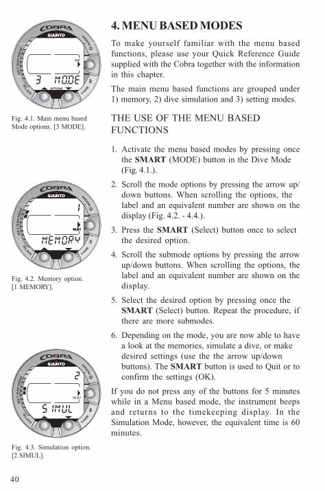
1. Activate the menu based modes by pressing oncethe SMART (MODE) button in the Dive Mode(Fig. 4.1.).
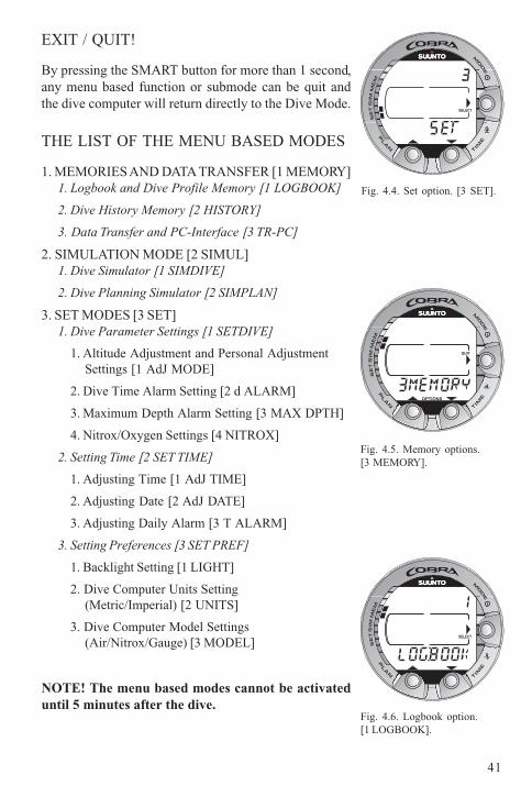
2. Scroll the mode options by pressing the arrow up/down buttons. When scrolling the options, thelabel and an equivalent number are shown on thedisplay (Fig. 4.2. - 4.4.).
3. Press the SMART (Select) button once to selectthe desired option.
4. Scroll the submode options by pressing the arrowup/down buttons. When scrolling the options, thelabel and an equivalent number are shown on thedisplay.
5. Select the desired option by pressing once theSMART (Select) button. Repeat the procedure, ifthere are more submodes.
6. Depending on the mode, you are now able to havea look at the memories, simulate a dive, or makedesired settings (use the the arrow up/downbuttons). The SMART button is used to Quit or toconfirm the settings (OK).
If you do not press any of the buttons for 5 minuteswhile in a Menu based mode, the instrument beepsand returns to the timekeeping display. In theSimulation Mode, however, the equivalent time is 60minutes.
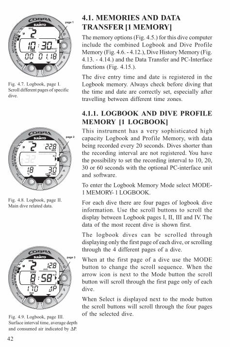
Fig. 4.3. Simulation option.[2 SIMUL].
Fig. 4.2. Memory option.[1 MEMORY].
Fig. 4.1. Main menu basedMode options. [3 MODE].
OPTIONS
QUIT
SELECTSELECTSELECT
SELECT
41
EXIT / QUIT!
By pressing the SMART button for more than 1 second,any menu based function or submode can be quit andthe dive computer will return directly to the Dive Mode.
THE LIST OF THE MENU BASED MODES
1. MEMORIES AND DATA TRANSFER [1 MEMORY]1. Logbook and Dive Profile Memory [1 LOGBOOK]
2. Dive History Memory [2 HISTORY]
3. Data Transfer and PC-Interface [3 TR-PC]
2. SIMULATION MODE [2 SIMUL]1. Dive Simulator [1 SIMDIVE]
2. Dive Planning Simulator [2 SIMPLAN]
3. SET MODES [3 SET]1. Dive Parameter Settings [1 SETDIVE]
1. Altitude Adjustment and Personal AdjustmentSettings [1 AdJ MODE]
2. Dive Time Alarm Setting [2 d ALARM]
3. Maximum Depth Alarm Setting [3 MAX DPTH]
4. Nitrox/Oxygen Settings [4 NITROX]
2. Setting Time [2 SET TIME]
1. Adjusting Time [1 AdJ TIME]
2. Adjusting Date [2 AdJ DATE]
3. Adjusting Daily Alarm [3 T ALARM]
3. Setting Preferences [3 SET PREF]
1. Backlight Setting [1 LIGHT]
2. Dive Computer Units Setting(Metric/Imperial) [2 UNITS]
3. Dive Computer Model Settings(Air/Nitrox/Gauge) [3 MODEL]
NOTE! The menu based modes cannot be activateduntil 5 minutes after the dive.
Fig. 4.4. Set option. [3 SET].
Fig. 4.5. Memory options.[3 MEMORY].
Fig. 4.6. Logbook option.[1 LOGBOOK].
SELECT
OPTIONS
QUIT
SELECT
42
4.1. MEMORIES AND DATATRANSFER [1 MEMORY]The memory options (Fig. 4.5.) for this dive computerinclude the combined Logbook and Dive ProfileMemory (Fig. 4.6. - 4.12.), Dive History Memory (Fig.4.13. - 4.14.) and the Data Transfer and PC-Interfacefunctions (Fig. 4.15.).
The dive entry time and date is registered in theLogbook memory. Always check before diving thatthe time and date are correctly set, especially aftertravelling between different time zones.
4.1.1. LOGBOOK AND DIVE PROFILEMEMORY [1 LOGBOOK]This instrument has a very sophisticated highcapacity Logbook and Profile Memory, with databeing recorded every 20 seconds. Dives shorter thanthe recording interval are not registered. You havethe possibility to set the recording interval to 10, 20,30 or 60 seconds with the optional PC-interface unitand software.
To enter the Logbook Memory Mode select MODE-1 MEMORY- 1 LOGBOOK.
For each dive there are four pages of logbook diveinformation. Use the scroll buttons to scroll thedisplay between Logbook pages I, II, III and IV. Thedata of the most recent dive is shown first.
The logbook dives can be scrolled throughdisplaying only the first page of each dive, or scrollingthrough the 4 different pages of a dive.
When at the first page of a dive use the MODEbutton to change the scroll sequence. When thearrow icon is next to the Mode button the scrollbutton will scroll through the first page only of eachdive.
When Select is displayed next to the mode buttonthe scroll buttons will scroll through the four pagesof the selected dive.
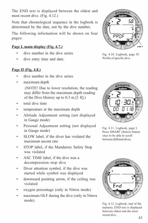
Fig. 4.7. Logbook, page I.Scroll different pages of specificdive.
Fig. 4.8. Logbook, page II.Main dive related data.
Fig. 4.9. Logbook, page III.Surface interval time, average depthand consumed air indicated by ∆P.
DIVE
TIME
page 1
SELECT
DIVE
MAX
TIME
O2%
DIVE
SLOW
page 2
QUIT
°C
OLF
STOP ASC TIME
DIVEDIVE
AVG
TIME
SURF
page 3
QUIT
bar
43
The END text is displayed between the oldest andmost recent dive. (Fig. 4.12.)
Note that chronological sequence in the logbook isdetermined by the date, not by the dive number.
The following information will be shown on fourpages:
Page I, main display (Fig. 4.7.)
• dive number in the dive series
• dive entry time and date.
Page II (Fig. 4.8.)
• dive number in the dive series
• maximum depth
(NOTE! Due to lower resolution, the readingmay differ from the maximum depth readingof the Dive History up to 0.3 m [1 ft].)
• total dive time
• temperature at the maximum depth
• Altitude Adjustment setting (not displayedin Gauge mode)
• Personal Adjustment setting (not displayedin Gauge mode)
• SLOW label, if the diver has violated themaximum ascent rate
• STOP label, if the Mandatory Safety Stopwas violated
• ASC TIME label, if the dive was adecompression stop dive
• Diver attention symbol, if the dive wasstarted while symbol was displayed
• downward pointing arrow, if the ceiling wasviolated
• oxygen percentage (only in Nitrox mode)
• maximum OLF during the dive (only in Nitroxmode).
Fig. 4.12. Logbook, end of thememory. END text is displayedbetween oldest and the mostrecent dive.
Fig. 4.10. Logbook, page IV.Profile of specific dive.
Fig. 4.11. Logbook, page I.Press SMART (Select) buttononce to be able to scrollbetween different dives.
DIVE
TIMEDIVE
page 4
QUIT
DIVE
TIMESELECT
QUIT
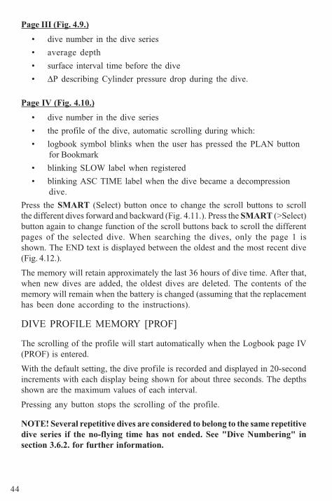
44
Page III (Fig. 4.9.)
• dive number in the dive series
• average depth
• surface interval time before the dive
• ∆P describing Cylinder pressure drop during the dive.
Page IV (Fig. 4.10.)
• dive number in the dive series
• the profile of the dive, automatic scrolling during which:
• logbook symbol blinks when the user has pressed the PLAN buttonfor Bookmark
• blinking SLOW label when registered
• blinking ASC TIME label when the dive became a decompressiondive.
Press the SMART (Select) button once to change the scroll buttons to scrollthe different dives forward and backward (Fig. 4.11.). Press the SMART (>Select)button again to change function of the scroll buttons back to scroll the differentpages of the selected dive. When searching the dives, only the page 1 isshown. The END text is displayed between the oldest and the most recent dive(Fig. 4.12.).
The memory will retain approximately the last 36 hours of dive time. After that,when new dives are added, the oldest dives are deleted. The contents of thememory will remain when the battery is changed (assuming that the replacementhas been done according to the instructions).
DIVE PROFILE MEMORY [PROF]
The scrolling of the profile will start automatically when the Logbook page IV(PROF) is entered.
With the default setting, the dive profile is recorded and displayed in 20-secondincrements with each display being shown for about three seconds. The depthsshown are the maximum values of each interval.
Pressing any button stops the scrolling of the profile.
NOTE! Several repetitive dives are considered to belong to the same repetitivedive series if the no-flying time has not ended. See "Dive Numbering" insection 3.6.2. for further information.
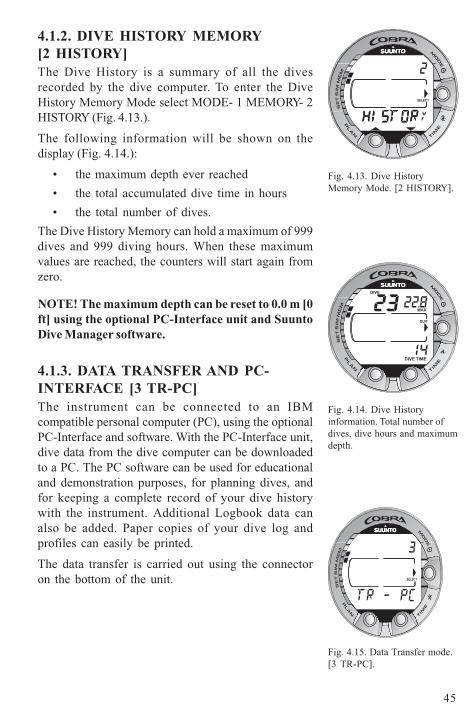
45
4.1.2. DIVE HISTORY MEMORY[2 HISTORY]The Dive History is a summary of all the divesrecorded by the dive computer. To enter the DiveHistory Memory Mode select MODE- 1 MEMORY- 2HISTORY (Fig. 4.13.).
The following information will be shown on thedisplay (Fig. 4.14.):
• the maximum depth ever reached
• the total accumulated dive time in hours
• the total number of dives.
The Dive History Memory can hold a maximum of 999dives and 999 diving hours. When these maximumvalues are reached, the counters will start again fromzero.
NOTE! The maximum depth can be reset to 0.0 m [0ft] using the optional PC-Interface unit and SuuntoDive Manager software.
4.1.3. DATA TRANSFER AND PC-INTERFACE [3 TR-PC]The instrument can be connected to an IBMcompatible personal computer (PC), using the optionalPC-Interface and software. With the PC-Interface unit,dive data from the dive computer can be downloadedto a PC. The PC software can be used for educationaland demonstration purposes, for planning dives, andfor keeping a complete record of your dive historywith the instrument. Additional Logbook data canalso be added. Paper copies of your dive log andprofiles can easily be printed.
The data transfer is carried out using the connectoron the bottom of the unit.
Fig. 4.14. Dive Historyinformation. Total number ofdives, dive hours and maximumdepth.
Fig. 4.13. Dive HistoryMemory Mode. [2 HISTORY].
Fig. 4.15. Data Transfer mode.[3 TR-PC].
SELECT
MAX
TIME
DIVE
DIVE
QUIT
SELECT
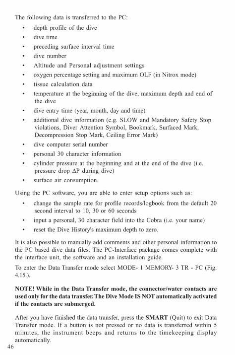
46
The following data is transferred to the PC:
• depth profile of the dive
• dive time
• preceding surface interval time
• dive number
• Altitude and Personal adjustment settings
• oxygen percentage setting and maximum OLF (in Nitrox mode)
• tissue calculation data
• temperature at the beginning of the dive, maximum depth and end ofthe dive
• dive entry time (year, month, day and time)
• additional dive information (e.g. SLOW and Mandatory Safety Stopviolations, Diver Attention Symbol, Bookmark, Surfaced Mark,Decompression Stop Mark, Ceiling Error Mark)
• dive computer serial number
• personal 30 character information
• cylinder pressure at the beginning and at the end of the dive (i.e.pressure drop ∆P during dive)
• surface air consumption.
Using the PC software, you are able to enter setup options such as:
• change the sample rate for profile records/logbook from the default 20second interval to 10, 30 or 60 seconds
• input a personal, 30 character field into the Cobra (i.e. your name)
• reset the Dive History's maximum depth to zero.
It is also possible to manually add comments and other personal information tothe PC based dive data files. The PC-Interface package comes complete withthe interface unit, the software and an installation guide.
To enter the Data Transfer mode select MODE- 1 MEMORY- 3 TR - PC (Fig.4.15.).
NOTE! While in the Data Transfer mode, the connector/water contacts areused only for the data transfer. The Dive Mode IS NOT automatically activatedif the contacts are submerged.
After you have finished the data transfer, press the SMART (Quit) to exit DataTransfer mode. If a button is not pressed or no data is transferred within 5minutes, the instrument beeps and returns to the timekeeping displayautomatically.
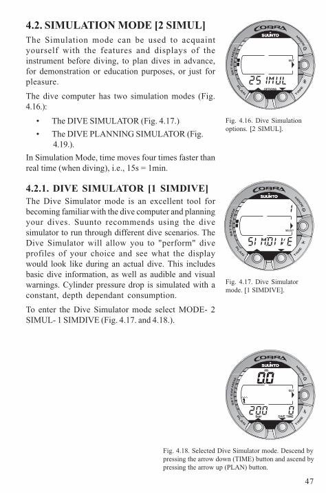
47
4.2. SIMULATION MODE [2 SIMUL]The Simulation mode can be used to acquaintyourself with the features and displays of theinstrument before diving, to plan dives in advance,for demonstration or education purposes, or just forpleasure.
The dive computer has two simulation modes (Fig.4.16.):
• The DIVE SIMULATOR (Fig. 4.17.)
• The DIVE PLANNING SIMULATOR (Fig.4.19.).
In Simulation Mode, time moves four times faster thanreal time (when diving), i.e., 15s = 1min.
4.2.1. DIVE SIMULATOR [1 SIMDIVE]The Dive Simulator mode is an excellent tool forbecoming familiar with the dive computer and planningyour dives. Suunto recommends using the divesimulator to run through different dive scenarios. TheDive Simulator will allow you to "perform" diveprofiles of your choice and see what the displaywould look like during an actual dive. This includesbasic dive information, as well as audible and visualwarnings. Cylinder pressure drop is simulated with aconstant, depth dependant consumption.
To enter the Dive Simulator mode select MODE- 2SIMUL- 1 SIMDIVE (Fig. 4.17. and 4.18.).
Fig. 4.16. Dive Simulationoptions. [2 SIMUL].
Fig. 4.18. Selected Dive Simulator mode. Descend bypressing the arrow down (TIME) button and ascend bypressing the arrow up (PLAN) button.
Fig. 4.17. Dive Simulatormode. [1 SIMDIVE].
OPTIONS
QUIT
SELECT
TIMEDIVE
m
QUIT
bar
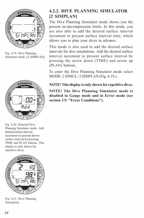
48
4.2.2. DIVE PLANNING SIMULATOR[2 SIMPLAN]The Dive Planning Simulator mode shows you thepresent no-decompression limits. In this mode, youare also able to add the desired surface intervalincrement to present surface interval time, whichallows you to plan your dives in advance.
This mode is also used to add the desired surfaceintervals for dive simulations. Add the desired surfaceinterval increment to present surface interval bypressing the arrow down (TIME) and arrow up(PLAN) buttons.
To enter the Dive Planning Simulator mode selectMODE- 2 SIMUL- 2 SIMPLAN (Fig. 4.19.).
NOTE! This display is only shown for repetitive dives.
NOTE! The Dive Planning Simulator mode isdisabled in Gauge mode and in Error mode (seesection 3.9. "Error Conditions").
Fig. 4.21. Dive PlanningSimulation.
Fig. 4.19. Dive PlanningSimulator mode. [2 SIMPLAN].
Fig. 4.20. Selected DivePlanning Simulator mode. Adddesired surface intervalincrement (to present shownsurface interval) by pressingTIME and PLAN buttons. Thisdisplay is only shown forrepetitive dives.
SELECT
TIME
SURF
OK
QUIT
DIVE
NO DEC TIME
MAX
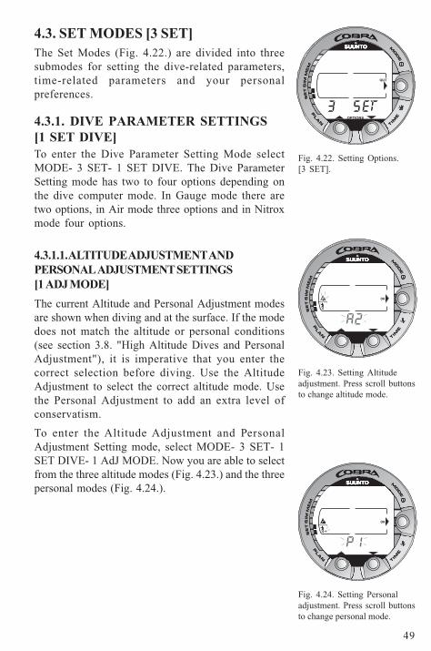
49
4.3. SET MODES [3 SET]The Set Modes (Fig. 4.22.) are divided into threesubmodes for setting the dive-related parameters,time-related parameters and your personalpreferences.
4.3.1. DIVE PARAMETER SETTINGS[1 SET DIVE]To enter the Dive Parameter Setting Mode selectMODE- 3 SET- 1 SET DIVE. The Dive ParameterSetting mode has two to four options depending onthe dive computer mode. In Gauge mode there aretwo options, in Air mode three options and in Nitroxmode four options.
4.3.1.1. ALTITUDE ADJUSTMENT ANDPERSONAL ADJUSTMENT SETTINGS[1 ADJ MODE]
The current Altitude and Personal Adjustment modesare shown when diving and at the surface. If the modedoes not match the altitude or personal conditions(see section 3.8. "High Altitude Dives and PersonalAdjustment"), it is imperative that you enter thecorrect selection before diving. Use the AltitudeAdjustment to select the correct altitude mode. Usethe Personal Adjustment to add an extra level ofconservatism.
To enter the Altitude Adjustment and PersonalAdjustment Setting mode, select MODE- 3 SET- 1SET DIVE- 1 AdJ MODE. Now you are able to selectfrom the three altitude modes (Fig. 4.23.) and the threepersonal modes (Fig. 4.24.).
Fig. 4.22. Setting Options.[3 SET].
Fig. 4.24. Setting Personaladjustment. Press scroll buttonsto change personal mode.
Fig. 4.23. Setting Altitudeadjustment. Press scroll buttonsto change altitude mode.
QUIT
OPTIONS
OK
OK
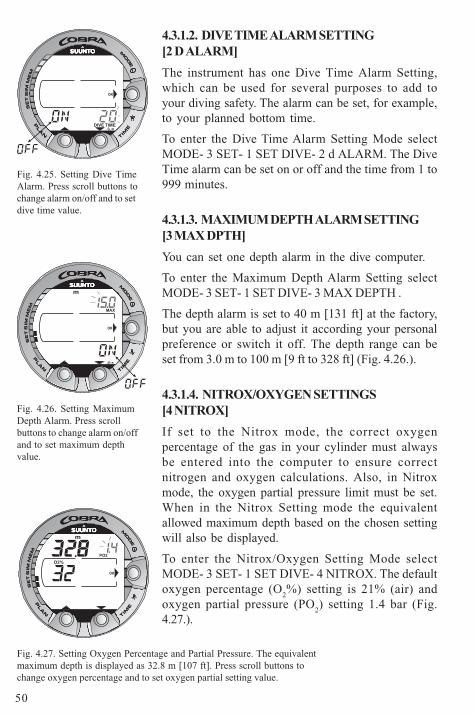
50
4.3.1.2. DIVE TIME ALARM SETTING[2 D ALARM]
The instrument has one Dive Time Alarm Setting,which can be used for several purposes to add toyour diving safety. The alarm can be set, for example,to your planned bottom time.
To enter the Dive Time Alarm Setting Mode selectMODE- 3 SET- 1 SET DIVE- 2 d ALARM. The DiveTime alarm can be set on or off and the time from 1 to999 minutes.
4.3.1.3. MAXIMUM DEPTH ALARM SETTING[3 MAX DPTH]
You can set one depth alarm in the dive computer.
To enter the Maximum Depth Alarm Setting selectMODE- 3 SET- 1 SET DIVE- 3 MAX DEPTH .
The depth alarm is set to 40 m [131 ft] at the factory,but you are able to adjust it according your personalpreference or switch it off. The depth range can beset from 3.0 m to 100 m [9 ft to 328 ft] (Fig. 4.26.).
4.3.1.4. NITROX/OXYGEN SETTINGS[4 NITROX]
If set to the Nitrox mode, the correct oxygenpercentage of the gas in your cylinder must alwaysbe entered into the computer to ensure correctnitrogen and oxygen calculations. Also, in Nitroxmode, the oxygen partial pressure limit must be set.When in the Nitrox Setting mode the equivalentallowed maximum depth based on the chosen settingwill also be displayed.
To enter the Nitrox/Oxygen Setting Mode selectMODE- 3 SET- 1 SET DIVE- 4 NITROX. The defaultoxygen percentage (O
2%) setting is 21% (air) and
oxygen partial pressure (PO2) setting 1.4 bar (Fig.
4.27.).
Fig. 4.26. Setting MaximumDepth Alarm. Press scrollbuttons to change alarm on/offand to set maximum depthvalue.
Fig. 4.27. Setting Oxygen Percentage and Partial Pressure. The equivalentmaximum depth is displayed as 32.8 m [107 ft]. Press scroll buttons tochange oxygen percentage and to set oxygen partial setting value.
Fig. 4.25. Setting Dive TimeAlarm. Press scroll buttons tochange alarm on/off and to setdive time value.
OK
TIMEDIVE
MAX
OK
m
O2%
PO2
m
OK
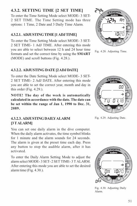
51
4.3.2. SETTING TIME [2 SET TIME]To enter the Time Setting Mode select MODE- 3 SET-2 SET TIME. The Time Setting mode has threeoptions: 1 Time, 2 Date and 3 Daily Time Alarm.
4.3.2.1. ADJUSTING TIME [1 ADJ TIME]
To enter the Time Setting Mode select MODE- 3 SET-2 SET TIME- 1 AdJ TIME. After entering this modeyou are able to select between 12 h and 24 hour timeformats and set the correct time by using the SMART(MODE) and scroll buttons (Fig. 4.28.).
4.3.2.2. ADJUSTING DATE [2 ADJ DATE]
To enter the Date Setting Mode select MODE- 3 SET-2 SET TIME- 2 AdJ DATE. After entering this modeyou are able to set the correct year, month and day inthis order (Fig. 4.29.).
NOTE! The day of the week is automaticallycalculated in accordance with the date. The date canbe set within the range of Jan 1, 1990 to Dec. 31,2089.
4.3.2.3. ADJUSTING DAILY ALARM[3 T ALARM]
You can set one daily alarm in the dive computer.When the daily alarm activates, the time symbol blinksfor 1 minute and the alarm sounds for 24 seconds.The alarm is given at the preset time each day. Pressany button to stop the audible alarm, after it hasactivated.
To enter the Daily Alarm Setting Mode to adjust thealarm select MODE- 3 SET- 2 SET TIME- 3 T ALARM.After entering this mode you are able to set the desiredalarm time (Fig. 4.30.).
Fig. 4.28. Adjusting Time.
Fig. 4.29. Adjusting Date.
Fig. 4.30. Adjusting DailyAlarm.
OK
OK
OKOK
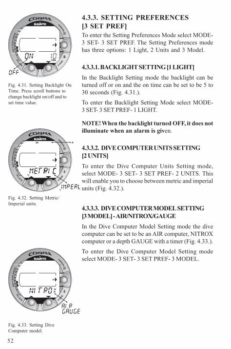
52
4.3.3. SETTING PREFERENCES[3 SET PREF]To enter the Setting Preferences Mode select MODE-3 SET- 3 SET PREF. The Setting Preferences modehas three options: 1 Light, 2 Units and 3 Model.
4.3.3.1. BACKLIGHT SETTING [1 LIGHT]
In the Backlight Setting mode the backlight can beturned off or on and the on time can be set to be 5 to30 seconds (Fig. 4.31.).
To enter the Backlight Setting Mode select MODE-3 SET- 3 SET PREF- 1 LIGHT.
NOTE! When the backlight turned OFF, it does notilluminate when an alarm is given.
4.3.3.2. DIVE COMPUTER UNITS SETTING[2 UNITS]
To enter the Dive Computer Units Setting mode,select MODE- 3 SET- 3 SET PREF- 2 UNITS. Thiswill enable you to choose between metric and imperialunits (Fig. 4.32.).
4.3.3.3. DIVE COMPUTER MODEL SETTING[3 MODEL] - AIR/NITROX/GAUGE
In the Dive Computer Model Setting mode the divecomputer can be set to be an AIR computer, NITROXcomputer or a depth GAUGE with a timer (Fig. 4.33.).
To enter the Dive Computer Model Setting modeselect MODE- 3 SET- 3 SET PREF- 3 MODEL.
Fig. 4.33. Setting DiveComputer model.
Fig. 4.32. Setting Metric/Imperial units.
Fig. 4.31. Setting Backlight OnTime. Press scroll buttons tochange backlight on/off and toset time value.
OK
TIME
OK
°C
°F
m ft
OK
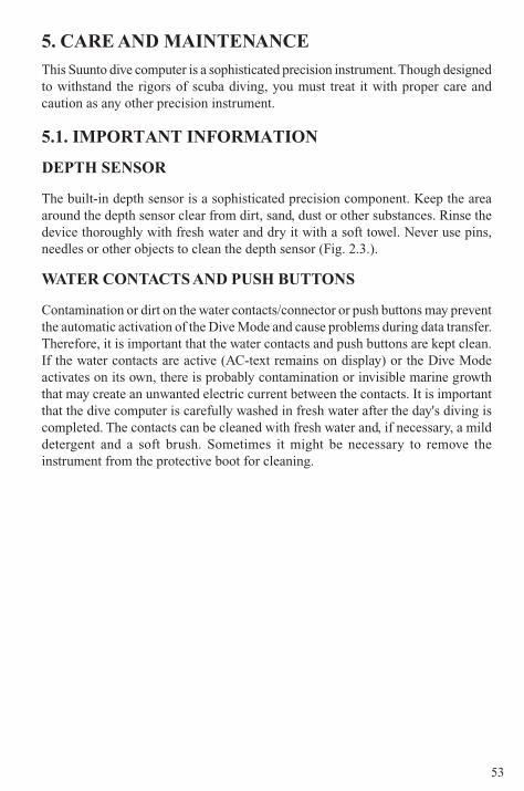
53
5. CARE AND MAINTENANCE
This Suunto dive computer is a sophisticated precision instrument. Though designedto withstand the rigors of scuba diving, you must treat it with proper care andcaution as any other precision instrument.
5.1. IMPORTANT INFORMATION
DEPTH SENSOR
The built-in depth sensor is a sophisticated precision component. Keep the areaaround the depth sensor clear from dirt, sand, dust or other substances. Rinse thedevice thoroughly with fresh water and dry it with a soft towel. Never use pins,needles or other objects to clean the depth sensor (Fig. 2.3.).
WATER CONTACTS AND PUSH BUTTONS
Contamination or dirt on the water contacts/connector or push buttons may preventthe automatic activation of the Dive Mode and cause problems during data transfer.Therefore, it is important that the water contacts and push buttons are kept clean.If the water contacts are active (AC-text remains on display) or the Dive Modeactivates on its own, there is probably contamination or invisible marine growththat may create an unwanted electric current between the contacts. It is importantthat the dive computer is carefully washed in fresh water after the day's diving iscompleted. The contacts can be cleaned with fresh water and, if necessary, a milddetergent and a soft brush. Sometimes it might be necessary to remove theinstrument from the protective boot for cleaning.
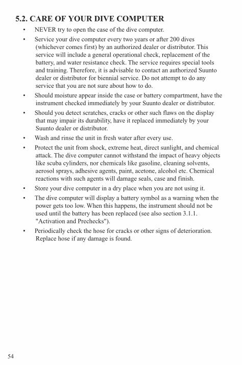
54
5.2. CARE OF YOUR DIVE COMPUTER• NEVER try to open the case of the dive computer.
• Service your dive computer every two years or after 200 dives(whichever comes first) by an authorized dealer or distributor. Thisservice will include a general operational check, replacement of thebattery, and water resistance check. The service requires special toolsand training. Therefore, it is advisable to contact an authorized Suuntodealer or distributor for biennial service. Do not attempt to do anyservice that you are not sure about how to do.
• Should moisture appear inside the case or battery compartment, have theinstrument checked immediately by your Suunto dealer or distributor.
• Should you detect scratches, cracks or other such flaws on the displaythat may impair its durability, have it replaced immediately by yourSuunto dealer or distributor.
• Wash and rinse the unit in fresh water after every use.
• Protect the unit from shock, extreme heat, direct sunlight, and chemicalattack. The dive computer cannot withstand the impact of heavy objectslike scuba cylinders, nor chemicals like gasoline, cleaning solvents,aerosol sprays, adhesive agents, paint, acetone, alcohol etc. Chemicalreactions with such agents will damage seals, case and finish.
• Store your dive computer in a dry place when you are not using it.
• The dive computer will display a battery symbol as a warning when thepower gets too low. When this happens, the instrument should not beused until the battery has been replaced (see also section 3.1.1."Activation and Prechecks").
• Periodically check the hose for cracks or other signs of deterioration.Replace hose if any damage is found.
55
5.3. MAINTENANCEThe instrument should be thoroughly rinsed with fresh water, then dried with asoft towel after each dive. Make sure that all salt crystals and sand particles havebeen flushed out.
Check the display and the transparent battery compartment cover for possiblemoisture or water. DO NOT use the dive computer, if you detect any moisture orwater inside.
CAUTION!
- Do not use compressed air to blow water off the unit. - Do not use solvents or other cleaning fluids that might cause damage. - Do not test or use the dive computer in pressurized air.
5.4. WATER RESISTANCE INSPECTIONEnsure the water resistance of the device. Always check the water resistance of thebattery compartment when replacing the battery. Moisture inside the device orbattery compartment will seriously damage the unit.
Check the transparent battery compartment cover and the display for any sign ofleaks. If you find moisture inside your dive computer, there is a leak. A leak mustbe corrected without delay, as moisture will seriously damage the unit, even beyondrepair. Suunto does not take any responsibility for damage caused by moisture inthe dive computer, if the instructions of this manual are not carefully followed.
In case of a leak, immediately take the dive computer to an authorized Suuntodealer or distributor. Only an authorized Suunto dealer or distributor should doservice activities.
5.5. BATTERY REPLACEMENTNOTE! It is imperative that the change is made in a proper manner to avoid anyleakage of water into the battery compartment or computer. When in doubt, it isadvisable to contact an authorized Suunto dealer for battery replacement.
NOTE! When the battery is changed, all nitrogen and oxygen uptake data is lost.Therefore, before changing the battery, the no-flying time shown by the computershould have reached zero. Otherwise, wait for 48 hours or preferably even 100hours before you dive again.
56
CAUTION!
Defects caused by improper battery installation are not covered by thewarranty.
All history and profile data, as well as the altitude, personal and alarm settings,will remain in the dive computer memory after the battery change. However, theclock time and time alarm setting is lost. In the Nitrox mode, the nitrox settingsrevert back to default settings (21% O
2, 1.4 bar PO
2).
When working with the battery compartment, cleanliness is extremely important.Even the smallest dirt particles may cause a leakage when you dive.
BATTERY KIT
The battery kit includes a 3.0 V coin type lithium cell battery and a lubricated O-ring. When handling the battery do not make contact with both of the poles at thesame time. Do not touch the surfaces of the battery with your bare fingers.
TOOLS REQUIRED
• A Philips screwdriver.
• Soft cloth for cleaning.
• Needlenose pliers or small screwdriver for turning securing ring.
BATTERY REPLACEMENT
The battery and the buzzer are located in the back of the instrument in a separatecompartment. Console and battery compartment parts are shown in Fig. 5.1. andFig. 5.2. To change the battery, follow the procedure below:
1. Unscrew the four screws at the back of the elastomer console and removethe back cover of the console.
2. Thoroughly rinse and dry the computer.
3. Open the securing ring of the battery compartment lid by pushing it downand rotating it clockwise. You may use a pointed nose pliers or a small
screwdriver as an aid to rotate. Put the pliers ends into the holes of thesecuring ring or the screwdriver onto the side of the right tooth on the ring(Fig. 5.3.) and turn the ring clockwise. Care should be taken not to damage
any of the parts.
4. Remove the ring.
57
5. Carefully remove the lid with the beeper attached to it. The lid can beremoved by pressing with your finger on the outermost edge of the lid
while at the same time pulling with your nail at the opposite side. Do notuse sharp metal objects as they might damage the O-ring or the sealingsurfaces.
6. Remove the O-ring and the battery retainer.
7. Carefully remove the battery. Do not damage the electrical contacts or thesealing surface.
Check for any traces of flooding, particularly between the beeper and the lid, orfor any other damage. In case of a leak or any other damage, bring the dive computerto an authorized Suunto dealer or distributor for check and repair.
8. Check the condition of the O-ring; a defective O-ring may indicate sealingor other problems. Dispose the old O-ring, even if it seems to be in goodcondition.
9. Check that the battery compartment, battery holder and lid are clean. Cleanwith soft cloth if necessary.
10. Check the polarity of the battery: the "-" mark should point toward thebottom of the compartment and the "+" mark upwards. Gently insert thenew battery in the battery compartment
11. Reinstall the battery retainer in its correct position.
12. Check that the new lubricated O-ring is in good condition. Put it in the rightposition in the battery compartment. Be very careful not to get any dirt onthe O-ring or its sealing surfaces.
13. Carefully press the lid onto the battery compartment with your thumb,while making sure that the O-ring is not at any point protruding out at theedge.
14. Put your other thumb through the locking ring. Press this thumb firmlyagainst the lid and release the other one. Make sure that the lid is pressedcompletely down!
15. Note the correct orientation of the locking ring. Turn the lockingring counterclockwise with your free thumb and fingers until it snaps intoits locked position.
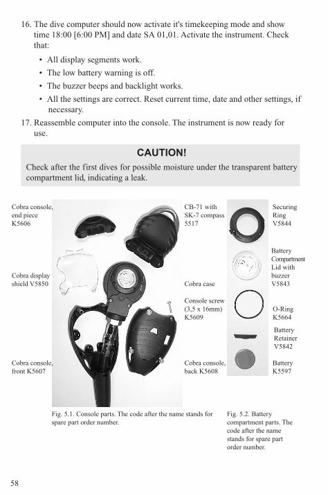
58
16. The dive computer should now activate it's timekeeping mode and showtime 18:00 [6:00 PM] and date SA 01,01. Activate the instrument. Checkthat:
• All display segments work.
• The low battery warning is off.
• The buzzer beeps and backlight works.
• All the settings are correct. Reset current time, date and other settings, ifnecessary.
17. Reassemble computer into the console. The instrument is now ready foruse.
CAUTION!
Check after the first dives for possible moisture under the transparent batterycompartment lid, indicating a leak.
Fig. 5.1. Console parts. The code after the name stands forspare part order number.
Console screw(3,5 x 16mm)K5609
Fig. 5.2. Batterycompartment parts. Thecode after the namestands for spare partorder number.
Cobra console,back K5608
Cobra console,front K5607
Cobra case
CB-71 withSK-7 compass5517
SecuringRingV5844
BatteryCompartmentLid withbuzzerV5843
O-RingK5664
BatteryK5597
BatteryRetainerV5842
Cobra displayshield V5850
Cobra console,end pieceK5606
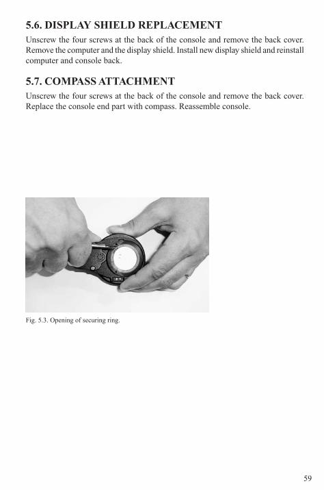
59
5.6. DISPLAY SHIELD REPLACEMENTUnscrew the four screws at the back of the console and remove the back cover.Remove the computer and the display shield. Install new display shield and reinstallcomputer and console back.
5.7. COMPASS ATTACHMENTUnscrew the four screws at the back of the console and remove the back cover.Replace the console end part with compass. Reassemble console.
Fig. 5.3. Opening of securing ring.
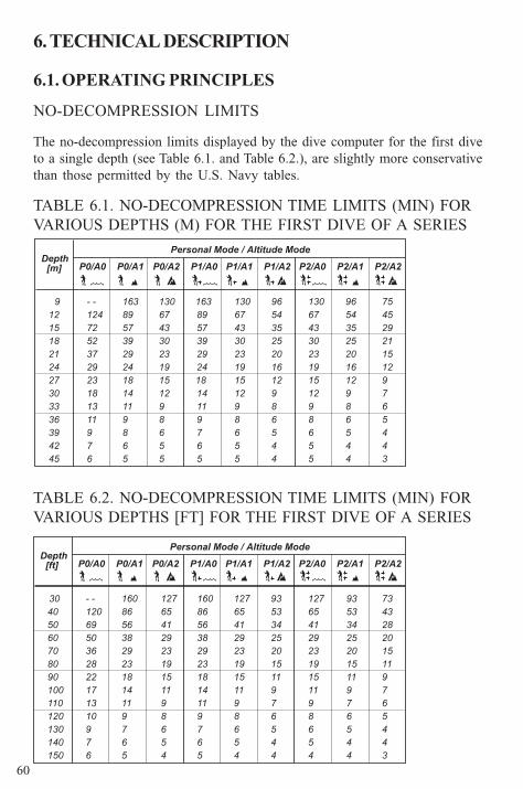
60
9
P0/A0 P0/A1 P0/A2 P1/A0 P1/A1 P1/A2 P2/A0 P2/A1 P2/A2
12
15
18
21
24
27
30
33
36
39
42
45
- -
124
72
52
37
29
23
18
13
11
9
7
6
163
89
57
39
29
24
18
14
11
9
8
6
5
130
67
43
30
23
19
15
12
9
8
6
5
5
89
57
39
29
24
14
11
9
7
6
5
130
67
43
30
23
19
15
12
9
8
6
5
5
96
54
35
25
20
16
12
9
8
6
5
4
4
130
67
43
30
23
19
15
12
9
8
6
5
5
96
54
35
25
20
16
12
9
8
6
5
4
4
75
45
29
21
15
12
9
7
6
5
4
4
3
163
18
Depth [m]
Personal Mode / Altitude Mode
30
P0/A0 P0/A1 P0/A2 P1/A0 P1/A1 P1/A2 P2/A0 P2/A1 P2/A2
40
50
60
70
80
90
100
110
120
130
140
150
- -
120
69
50
36
28
22
17
13
10
9
7
6
160
86
56
38
29
23
18
14
11
9
7
6
5
127
65
41
29
23
19
15
11
9
8
6
5
4
93
53
34
25
20
15
11
9
7
6
5
4
4
73
43
28
20
15
11
9
7
6
5
4
4
3
160
86
56
38
29
23
18
14
11
9
7
6
5
127
65
41
29
23
19
15
11
9
8
6
5
4
127
65
41
29
23
19
15
11
9
8
6
5
4
93
53
34
25
20
15
11
9
7
6
5
4
4
Depth [ft]
Personal Mode / Altitude Mode
6. TECHNICAL DESCRIPTION
6.1. OPERATING PRINCIPLES
NO-DECOMPRESSION LIMITS
The no-decompression limits displayed by the dive computer for the first diveto a single depth (see Table 6.1. and Table 6.2.), are slightly more conservativethan those permitted by the U.S. Navy tables.
TABLE 6.1. NO-DECOMPRESSION TIME LIMITS (MIN) FORVARIOUS DEPTHS (M) FOR THE FIRST DIVE OF A SERIES
TABLE 6.2. NO-DECOMPRESSION TIME LIMITS (MIN) FORVARIOUS DEPTHS [FT] FOR THE FIRST DIVE OF A SERIES
61
ALTITUDE DIVING
The atmospheric pressure is lower at high altitudes than at sea level. Aftertraveling to a higher altitude, the diver will have additional nitrogen in hisbody, compared to the equilibrium situation at the original altitude. This"additional" nitrogen is released gradually in time and equilibrium is reached. Itis recommended that you acclimate to the new altitude by waiting at least threehours before making a dive.
Before high altitude diving, the instrument must be set to the AltitudeAdjustment mode to adjust the calculations for the new altitude. The maximumpartial pressures of nitrogen allowed by the mathematical model of the divecomputer are reduced according to the lower ambient pressure.
As a result, the allowed no-decompression stop limits are considerably reduced.
SURFACE INTERVALS
The dive computer requires a minimum surface interval of 5 minutes betweendives. If a surface interval is shorter than 5 minutes, the next dive is treated asa continuation of the previous dive.
62
6.2. REDUCED GRADIENT BUBBLE MODEL,SUUNTO RGBMThe Suunto Reduced Gradient Bubble Model (RGBM) is a modern algorithmfor predicting both dissolved and free gas in the tissues and blood of divers. Itwas developed in a co-operation between Suunto and Bruce R. Wienke BSc,MSc. PhD. It is based on both laboratory experiments and diving data, includingdata from DAN.
It is a significant advance on the classical Haldane models, which do notpredict free gas (microbubbles). The advantage of Suunto RGBM is additionalsafety through its ability to adapt to a wide variety of situations. Suunto RGBMaddresses a number of diving circumstances outside the range of just dissolvedgas models by:
• Monitoring continuous multiday diving
• Computing closely spaced repetitive diving
• Reacting to a dive deeper than the previous dive
• Adapting for rapid ascents which produce high micro-bubble (silent-bubble) build-up
• Incorporating consistency with real physical laws for gas kinetics.
SUUNTO RGBM ADAPTIVE DECOMPRESSION
The SUUNTO RGBM algorithm adapts its predictions of both the effects ofmicro-bubble build-up and adverse dive profiles in the current dive series. Itwill also change these calculations according to the personal adjustment youselect.
The pattern and speed of decompression at the surface is adjusted accordingto micro-bubble influence.
Also on repetitive dives adjustment may be applied to the maximum allowablenitrogen overpressure in each theoretical tissue group.
Depending on circumstances Suunto RGBM will adapt the decompressionobligations by doing any or all of the following:
• Reducing no-decompression stop dive times
• Adding Mandatory Safety Stops
• Increasing decompression stop times
• Advising an extended surface interval (Diver Attention symbol).
63
DIVER ATTENTION SYMBOL - ADVICE TO EXTENDSURFACE INTERVAL
Some patterns of diving cumulatively add a higher risk of DCI, e.g. dives withshort surface intervals, repetitive dives deeper than earlier ones, multipleascents, substantial multiday diving. When this is detected in addition toadapting the decompression algorithm Suunto RGBM will in somecircumstances also advise, with the Diver Attention Symbol (review page 33)that the diver extend the surface interval
6.3. OXYGEN EXPOSUREThe oxygen exposure calculations are based on currently accepted exposuretime limit tables and principles. In addition to this the dive computer usesseveral methods to conservatively estimate the oxygen exposure. These includefor example:
• the displayed oxygen exposure calculations are rounded to the nexthigher whole percentage value
• for recreational scuba diving, the recommended upper limit of 1.4 barPO
2 is used as a default
• the CNS% limits up to 1.4 bar are based on 1991 NOAA DivingManual limits, but the limits higher than 1.4 bar are significantlyshortened
• the OTU monitoring is based on the long-term daily tolerance leveland the recovery rate is reduced.
Oxygen related information displayed by the dive computer is also designed toensure all warnings and displays in the appropriate phases of a dive. E.g. thefollowing information will be shown before and during a dive, when the computeris set in Nitrox mode:
• the selected O2%
• the color-coded OLF% bar graph for either CNS% or OTU%
• audible alarms are given and the OLF bar graph starts to blink whenthe 80% and 100% limits are exceeded
• the blinking of the bar graph stops, when the PO2 is below 0.5 bar
• audible alarms are given and the actual PO2 value blinks when it
exceeds the preset limit
• in dive planning the maximum depth according to the O2% and
maximum PO2 selected.
64
6.4. TECHNICAL SPECIFICATIONDimensions and weight:
• Diameter: width 73mm [2.85in], length 165mm [6.50in].
• Thickness: 35mm [1.40in].
• Weight: 210g without hose [7.4 oz].
Depth Gauge:
• Temperature compensated pressure sensor.
• Salt water calibrated, in fresh water the readings are about 3% smaller(calibrated complying with prEN 13319).
• Maximum depth of operation: 80 m [262 ft] (complying with prEN13319).
• Accuracy: ± 1% of full scale or better from 0 to 80 m [262 ft] at 20°C[68°F] (complying with prEN 13319).
• Depth display range: 0 … 150 m [492 ft].
• Resolution: 0.1 m from 0 to 100 m [1 ft from 0 to 328 ft].
Cylinder Pressure Gauge
• Rated working pressure: 300 bar [4000 psi], maximum allowedpressure 360 bar [5000 psi].
• Resolution: 1 bar [10 psi].
Temperature display:
• Resolution: 1°C [1.5°F].
• Display range: -9 ... +50°C [-9 ... +122°F].
• Accuracy: ± 2°C [± 3.6°F] within 20 minutes of temperature change.
Calendar Clock:
• Accuracy: ± 25 s/month (at 20°C [68°F]).
• 12/24 h display.
Other displays:
• Dive time: 0 to 999 min, counting starts and stops at 1.2 m [4 ft] depth.
• Surface time: 0 to 99 h 59 min.
• Dive counter: 0 to 99 for repetitive dives.
• No-decompression time: 0 to 199 min (- - after 199).
• Ascent time: 0 to 99 min (- - after 99).
• Ceiling depths: 3.0 to 100 m [10 to 328 ft].
• Air time: 0 to 99 min (- - after 99).
65
Displays only in Nitrox mode:
• Oxygen%: 21 - 50.
• Oxygen partial pressure display: 1.2 - 1.6 bar depending on the limitsetting.
• Oxygen Limit Fraction: 1 - 110% with 10% resolution (bar graph).
Logbook/Dive Profile Memory:
• Recording interval: 20 seconds (the recording interval can be set to10s, 30s or 60s with the optional PC-interface unit and software),records the maximum depth of each interval.
• Memory capacity: approximately 36 hours of diving with 20 secondsrecording interval.
• Depth accuracy: 0.3 m [1 ft].
Operating Conditions
• Normal altitude range: 0 to 3000 m [10000 ft] above sea level.
• Operating temperature: 0°C to 40°C [32°F to 104°F].
• Storage temperature: -20°C to +50°C [-4°F to +122°F].
It is recommended that the instrument be stored in a dry place atroom temperature.
NOTE! Do not leave the dive computer in direct sunlight!
Tissue Calculation Model
• Suunto RGBM algorithm (developed by SUUNTO and Bruce R.Wienke, BS, MS and PhD).
• 9 tissue compartments.
• Tissue compartment halftimes: 2.5, 5, 10, 20, 40, 80, 120, 240 and 480minutes (on gassing). The off gassing halftimes are slowed down.
• Reduced gradient (variable) "M" values based on diving habit anddive violations. The "M" values are tracked up to 100 hours after adive.
• The EAN and oxygen exposure calculations are based onrecommendations by R.W. Hamilton, PhD and currently acceptedexposure time limit tables and principles.
66
Battery
• One 3 V lithium battery: CR 2450 (K5597) and O-ring 1,78 mm x 31,47mm 70 ShA (K5664).
• Battery storage time (shelf life): Up to three years.
• Replacement: Every two years or more often depending on dive activity.
• Life expectancy at 20°C [68°F]:
- 0 dives/y -> 3 years
- 100 dives/y -> 2 years
- 400 dives/y -> 1 year
The following conditions have an affect on the expected battery lifetime:
• The length of the dives.
• The condition in which the unit is operated and stored (e.g. temperature/cold conditions). Below 10°C [50°F] the expected battery lifetime isabout 50-75% of that at 20°C [68°F].
• The use of the backlight and audible alarms.
• The quality of the battery (some lithium batteries may exhaustunexpectedly, which cannot be tested in advance).
• The time the dive computer has been stored until it gets to thecustomer. The battery is installed into the unit at the factory.
NOTE! Low temperature or an internal oxidation of the battery may cause thebattery warning even though the battery has enough capacity. In this case, thewarning usually disappears when the Dive Mode is activated again.
67
7. WARRANTY
NOTE! The warranty arrangements are different in different countries. Thedive computer packaging contains information regarding the warranty benefitsand requirements applicable to your purchase.
This Suunto dive computer is warranted against defects in workmanship andmaterials for a period of two years after purchase to the original owner subjectto and in accordance with the terms and conditions set forth below:
The dive computer should be serviced or repaired only by an authorized Suuntodealer or distributor.
This warranty does not cover damage to the product resulting from improperusage, improper maintenance, neglect of care, alteration or unauthorized repair.This warranty will automatically become void if proper preventive maintenanceprocedures have not been followed as outlined in the use and care instructionsfor this product.
If a claim under this or any other warranty appears to be necessary, return theproduct, freight prepaid, to your Suunto dealer or distributor or qualified repairfacility. Include your name and address, proof of purchase and/or serviceregistration card, as required in your country. The claim will be honored andthe product repaired or replaced at no charge and returned in what your Suuntodealer or distributor determines a reasonable amount of time, provided allnecessary parts are in stock. All repairs made, not covered under the terms ofthis warranty, will be made at the owner's expense. This warranty is non-transferable from the original owner.
All implied warranties, including but not limited to the implied warranties ofmerchantability and fitness for a particular purpose, are limited from date ofpurchase and in scope to the warranties expressed herein. Suunto shall not beliable for loss of use of the product or other incidental or consequential costs,expenses or damage incurred by the purchase. All warranties not stated hereinare expressly disclaimed.
Some states do not allow the exclusion or limitation of implied warranties ofconsequential damages, so the above exclusions or limitations may not applyto you. This warranty gives you specific legal rights, and you may also haveother rights that vary from state to state.
This warranty does not cover any representation or warranty made by dealersor representatives beyond the provisions of this warranty. No dealer orrepresentation is authorized to make any modifications to this warranty or tomake any additional warranty.
Battery replacement is not covered by this warranty.
This Instruction Manual should be kept with your dive computer.
68
8. GLOSSARYAir Time The amount of dive time remaining, based on a calculation of
cylinder pressure and ambient pressure and present airconsumption.
Altitude dive A dive made at an elevation greater than 300 m [1000 ft] abovesea level.
Ascent rate The speed at which the diver ascends toward the surface.
ASC RATE Abbreviation for ascent rate.
Ascent time The minimum amount of time needed to reach the surface on adecompression stop dive.
ASC TIME Abbreviation for ascent time.
Ceiling On a decompression stop dive the shallowest depth to which adiver may ascend based on computer nitrogen load.
Ceiling Zone On a decompression stop dive the zone between the ceiling andthe ceiling plus 1.8 m [6 ft]. This depth range is displayed withthe two arrows pointing toward each other (the "hour glass"icon).
CNS Abbreviation for Central Nervous System toxicity.
Central Nervous System Toxicity
Toxicity caused by oxygen. Can cause a variety of neurologicalsymptoms. The most important of which is an epileptic-likeconvulsion which can cause a diver to drown.
CNS% Central Nervous System toxicity limit fraction. Also noteOxygen Limit Fraction
Compartment See "Tissue group".
DAN Divers Alert Network.
DCI Abbreviation for decompression illness.
Decompression Time spent at a decompression stop or range before surfacing,to allow absorbed nitrogen to escape naturally from tissues.
Decompression range On a decompression stop dive the depth range, between thefloor and ceiling, within which a diver must stop for some timeduring ascent.
Decompression illness
Any of a variety of maladies resulting either directly or indirectlyfrom the formation of nitrogen bubbles in tissues or body fluids,as a result of inadequately controlled decompression. Commonlycalled "bends" or "DCI".
69
Dive series A group of repetitive dives between which the dive computerindicates some nitrogen loading is present. When nitrogenloading reaches zero the dive computer deactivates.
Dive time Elapsed time between leaving the surface to descend, andreturning to the surface at the end of a dive.
∆ P Delta P, describing the Cylinder Pressure drop during the dive;difference in tank pressure between beginning and end of dive.
EAD Abbreviation for equivalent air depth.
EAN Abbreviation for enriched air nitrox.
Enriched Air Nitrox Also called Nitrox or Enriched Air = EANx. Air that has someoxygen added. Standard mixes are EAN32 (NOAA Nitrox I =NN I) and EAN36 (NOAA Nitrox II = NN II).
Equivalent Air Depth Nitrogen partial pressure equivalent table.
Floor The deepest depth during a decompression stop dive at whichdecompression takes place.
Half-time After a change in ambient pressure, the amount of time requiredfor the partial pressure of nitrogen in a theoretical compartmentto go half-way from its previous value to saturation at the newambient pressure.
HP Abbreviation for high pressure (= cylinder pressure).
Multi-level dive A single or repetitive dive that includes time spent at variousdepths and whose no-decompression limits are therefore notdetermined solely by the maximum depth attained.
NITROX In sports diving refers to any mix with a higher fraction ofoxygen than standard air.
NOAA United States National Oceanic and AtmosphericAdministration.
No-decompression time
The maximum amount of time a diver may remain at a particulardepth without having to make decompression stops during thesubsequent ascent.
No-decompression dive
Any dive which permits a direct, uninterrupted ascent to thesurface at any time.
NO DEC TIME Abbreviation for no-decompression time limit.
OEA = EAN = EANx Abbreviation for Oxygen Enriched Air Nitrox.
OLF Abbreviation for Oxygen Limit Fraction.
OTU Abbreviation for Oxygen Tolerance Unit.
70
Oxygen Tolerance Unit
Is used to measure the Whole-Body-Toxicity.
Oxygen Limit Fraction
A term used by SUUNTO for the values displayed in theOxygen Toxicity bargraph. The value is either the CNS% or theOTU%.
O2% Oxygen percentage or oxygen fraction in the breathing gas.
Standard air has 21% oxygen.
Oxygen partial pressure
Limits the maximum depth to which the used Nitrox mixturecan safely be used. The maximum partial pressure limit forenriched air diving is 1.4 bar. The contingency partial pressurelimit is 1.6 bar. Dives beyond this limit have the risk forimmediate oxygen toxicity.
PO2
Abbreviation for oxygen partial pressure.
RGBM Abbreviation for Reduced Gradient Bubble Model.
Reduced Gradient Bubble Model
Modern algorithm for tracking both dissolved and free gas indivers.
Repetitive dive Any dive whose decompression time limits are affected byresidual nitrogen absorbed during previous dives.
Residual nitrogen The amount of excess nitrogen remaining in a diver after one ormore dives.
SURF TIME Abbreviation for surface interval time.
Surface interval timeElapsed time between surfacing from a dive and beginning adescent for the subsequent repetitive dive.
Tissue group Theoretical concept used to model bodily tissues for theconstruction of decompression tables or calculations.
Whole-Body Toxicity Another form of oxygen toxicity, which is caused by prolongedexposure to high oxygen partial pressures. The most commonsymptoms are irritation in the lungs, a burning sensation in thechest, coughing and reduction of the vital capacity. Also calledPulmonary Oxygen Toxicity. See also OTU.

71

72
Printed in Finland 02.2004/5000 Esa Print Oy / 140124
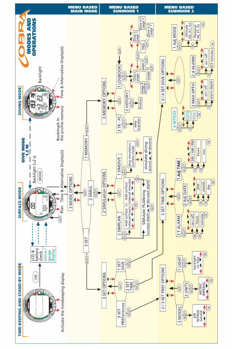
Act
ivat
e th
e ti
mek
eep
ing
dis
pla
y
LCD
&b
atte
rych
eck
nit
rox
/g
aug
ed
isp
lay
Plan
Bac
klig
ht
ON
MO
DE
Bac
klig
ht
(>2
s)
3 SE
T1
MEM
OR
Y2
SIM
UL
3 M
OD
E O
PTIO
NS
sim
ula
te d
ivin
gas
cen
dd
esce
nd
Ad
d s
urf
ace
inte
rval
ho
urs
Ad
d s
urf
ace
inte
rval
min
ute
s
2 SI
MPL
AN
1 SI
MD
IVE
div
e si
mu
lati
on
:su
rfac
e m
od
e
2 SI
MU
Lati
on
OPT
ION
S
3 TR
- P
C1
LOG
BO
OK
dat
atr
ansf
er
2 H
ISTO
RY
Div
e n
pag
e 1
pag
e 4
pro
file
pag
e 2
pag
e 3
Div
e n
pag
e 1
END
Div
e n
-1p
age
1
3 M
EMO
RY
OPT
ION
S
his
tory
MENU BASEDMAIN MODE
MENU BASED SUBMODE 1
MENU BASED SUBMODE 2
Bo
okm
ark
inth
e p
rofi
le m
emo
ryTi
me
& A
lter
nat
ive
Dis
pla
y(s)
MO
DES A
ND
OP
ER
AT
ION
S
DIV
E M
OD
E1.
2 M
TIM
E-K
EEPIN
G A
ND
STA
ND
-BY
MO
DE
SU
RFA
CE M
OD
ED
IVIN
G M
OD
E
bac
klig
ht
on
tim
e
2 / 3
SET
PR
EF O
PTIO
NS
3 M
OD
EL1
LIG
HT
2 U
NIT
S
MET
RIC
IMPE
RIA
L
AIR
NIT
RO
XG
AU
GE
3 SE
T TI
ME
OPT
ION
S
3 T
ALA
RM
1 A
dj T
IME
1 A
dj T
IME
on
/ o
ffh
ou
rs
min
ute
sye
ar
mo
nth
day
24h
/ A
M /
PM
ho
urs
min
2 A
dj D
ATE
3 / 4
SET
DIV
E O
PTIO
NS
Div
e n
-2p
age
1
Tim
e &
Alt
ern
ativ
e D
isp
lay(
s)
3 S
ETPR
EFer
ence
s1
SET
DIV
E2
SET
TIM
E
3 SE
T O
PTIO
NS
OK
OK
OK
OK
OK
OK
4 N
ITR
OX
PO2
O2%
3 M
AX
DPT
H
alar
m d
epth
on
/ o
ff
1 A
dj M
OD
E
Pers
on
alP0
, P1,
P2
Alt
itu
de
A0,
A1,
A2
DT
min
ute
s
on
/ o
ff
2 d
ALA
RM
TIM
ED
IVE
m
ba
r
m
NO
DE
C T
IME
TC B
MA
X
DIV
E T
IME
MA
X
ba
r
AIR
TIM
E
QU
IT
SELE
CT
SELE
CT
QU
IT
SELE
CT
SELE
CT
QU
IT
SELE
CT
SELE
CT
QU
IT
SELE
CT
SELE
CT
OK
OK
OK
QU
IT
SIM
ula
te P
LAN
nin
gin
crea
se d
epth
dec
reas
e d
epth
QU
IT
QU
IT
SELE
CT
SELE
CT
SELE
CT
SELE
CT
QU
IT
QU
IT
SELE
CT
QU
IT
SELE
CT
SELE
CT
OK
OK
OK
OK
QU
IT
OK
OK
SELE
CT
SELE
CT
SELE
CT
SELE
CT
QU
IT
OK
SELE
CT
SELE
CT
OK
OK
OK
SELE
CT
OK
OK
OK
QU
IT
QU
ITQ
UIT
������
�����
�� �������������
������������������� �������
� ������ �
� �������� ��
� ����� ����� ���� �������������
���
�������
�� �
���� ��
���������
����� ���
Mo
de
l of
Co
mp
ute
r:
E-m
ail
�� �!"�#���##���!
����������� ���������� ��� �����������
����� ������ ��������������
��$������� �
��������������������
�� �����%���� ���������
&������� ���
������� ��������
'(�)����������
��� �
�������������������������� ������$�
����� ���� � �
��������� �������� ������
��������������������(����������� �
������� ������
� ����� �������������(
�����
����� ����������
� �������������*�� � �
������ ���
�������%������ ������ ��� ���
�����(��
���������� ��������� ���%��� �
�
������ �� ��������� ������ ��
�����
�������������+������������ ������+
������ ��������+��� ��� ���+��
�������� ���
��������� �������� ����,���������(

Valimotie 7FIN-01510 Vantaa, FinlandTel. +358 9 875 870Fax +358 9 875 87301www.suunto.com