Embed Size (px)
Citation preview
Code Compliant Repair and Protection Guide
800-999-5099 | www.strongtie.com
PR
OF
ES
SIO
NA
LS
FOR THE INSTALLATION OF UTILITIES IN WOOD FRAME CONSTRUCTION
The expiration date of this document has been extended until 3/31/12.

2 | CODE COMPLIANT REPAIR AND PROTECTION GUIDE F-REPRPROTECT09 © 2009 SIMPSON STRONG-TIE COMPANY INC.
CONTENTS
Simpson Strong-Tie Company Inc. warrants catalog products to be free from defects in material or manufacturing. Simpson Strong-Tie Company Inc. products are further warranted for adequacy of design when used in accordance with design limits in this catalog and when properly specified, installed, and maintained. This warranty does not apply to uses not in compliance with specific applications and installations set forth in this catalog, or to non-catalog or modified products, or to deterioration due to environmental conditions.
Simpson Strong-Tie® connectors are designed to enable structures to resist the movement, stress, and loading that results from impact events such as earthquakes and high velocity winds. Other Simpson Strong-Tie products are designed to the load capacities and uses listed in this flier. Properly-installed Simpson Strong-Tie products will perform in accordance with the specifications set forth in the applicable Simpson Strong-Tie catalog. Additional performance limitations for specific products may be listed on the applicable catalog pages.
Due to the particular characteristics of potential impact events, the specific design and location of the structure, the building materials used, the quality of construction, and the
condition of the soils involved, damage may nonetheless result to a structure and its contents even if the loads resulting from the impact event do not exceed Simpson Strong-Tie catalog specifications and Simpson Strong-Tie connectors are properly installed in accordance with applicable building codes.
All warranty obligations of Simpson Strong-Tie Company Inc. shall be limited, at the discretion of Simpson Strong-Tie Company Inc., to repair or replacement of the defective part. These remedies shall constitute Simpson Strong-Tie Company Inc.’s sole obligation and sole remedy of purchaser under this warranty. In no event will Simpson Strong-Tie Company Inc. be responsible for incidental, consequential, or special loss or damage, however caused.
This warranty is expressly in lieu of all other warranties, expressed or implied, including warranties of merchantability or fitness for a particular purpose, all such other warranties being hereby expressly excluded. This warranty may change periodically – consult our website www.strongtie.com for current information.
LIMITED WARRANTY
Repair and Protection Products ..................................................................... 3Plumbing/MechanicalTop and Bottom Plates Allowed by Code ......................................................................................... 4 Repair/Protection ........................................................................................ 5Studs Allowed by Code ........................................................................................ 6 Repair/Protection ........................................................................................ 7Heating, Ventilation and Air Conditioning (HVAC)Top and Bottom Plates Allowed by Code ........................................................................................ 8 Repair/Protection ........................................................................................ 9ElectricalTop Plate, Bottom Plate and Studs Allowed by Code ...................................................................................... 10 Repair/Protection ..................................................................................... 10Technical Information .................................................................................... 11
A WORD ABOUT BUILDING CODES
International Residential Code, International Building Code, International Plumbing Code, International Mechanical Code are registered trademarks of International Code Council, Inc. National Electrical Code is a registered trademark of National Fire Protection Association. The Uniform Plumbing Code is a registered trademark of the International Association of Plumbing and Mechanical Officials.
All of the major building codes feature regulations on the size and/or location of penetrations in wood members for plumbing, HVAC and electrical components. In many cases, in order to comply with the code, hardware is required to:
• Reinforce wood members • Protect utilities within the wall
This guide is intended to illustrate the penetrations that are allowed under the various codes with and without repair or
protection. Simpson Strong-Tie® offers a range of products to help meet these code requirements.
The information in this guide is a summary of requirements from the 2003, 2006 and 2009 International Residential Code (IRC), International Building Code (IBC), International Plumbing Code (IPC), International Mechanical Code (IMC), 2006 Uniform Plumbing Code (UPC) and the 2005 National Electrical Code.

F-REPRPROTECT09 © 2009 SIMPSON STRONG-TIE COMPANY INC. CODE COMPLIANT REPAIR AND PROTECTION GUIDE | 3
REPAIR AND PROTECTION PRODUCTS
PSPN516 Repair and Shield Plate: Reinforcement and ProtectionRepair and shield plates reinforce top or bottom plates drilled or cut during construction. They also protect piping within the wall. They are 16 gauge steel, install with 16d nails, and protrude at least 2" above or below single or double plates to meet the requirements of the code for repair and protection. They are available with a standard galvanized coating or a ZMAX® galvanized coating for added corrosion resistance for use with some preservative-treated lumber. See page 11 for complete fastener and load information.
RPS Repair Strap: ReinforcementRepair straps reinforce top and bottom plates notched or cut during construction. They are 16 gauge steel and install with 16d nails to meet the requirements of the code for repair. They are available with a standard galvanized coating or a ZMAX® galvanized coating for added corrosion resistance for use with some preservative-treated lumber. See page 11 for complete fastener and load information.
MSTC Strap: ReinforcementMSTC straps reinforce top or bottom plates drilled or cut during construction. They are 16 gauge steel and install with 16d nails to meet the requirements of the code for repair. Recommended for applications where two plate penetrations are too close together for separate RPS straps to be installed (example: HVAC chase). See page 11 for complete fastener and load information.
HSS Heavy-Duty Stud Shoe: Reinforcement and ProtectionHeavy-duty stud shoes provide extra reinforcing to studs bored or notched during construction and protect piping within the wall. HSS install with SDS ¹⁄₄" diameter wood screws (included) and resist tension as well as compression loads. Suitable for piping with a maximum outside diameter of 2³⁄₈", they are available in sizes for single, double and triple 2x studs as well as single 4x studs. Made from 16 gauge steel to meet the protection requirements of the code, they feature a galvanized coating. See page 11 for complete fastener and load information.
SS Stud Shoe: Reinforcement and ProtectionStud shoes reinforce studs bored or notched during construction and protect piping within the wall. Suitable for piping with a maximum outside diameter of 2³⁄₈", they are available in sizes for single, double and triple 2x studs as well as single 3x studs. Made from 16 gauge steel to meet the protection requirements of the code and feature a galvanized coating. Stud shoes resist compression loads only, see page 11 for complete fastener and load information.
PSPN58 Shield Plate: ProtectionShield plates prevent penetration of fasteners into wiring or piping at the top and bottom plates of the walls. They are 16 gauge steel and protrude at least 2" above/below single or double plates to meet the protection requirements of the code. They are available with a standard galvanized coating or a ZMAX® galvanized coating for added corrosion resistance for use with some preservative-treated lumber.
NS Nail Stop: ProtectionNail stops prevent penetration of fasteners into wiring or piping. They are 16 gauge steel to meet the protection requirements of the code and feature a galvanized coating. Install with prongs or 8d common nails.
SE 6- 6d NAI SOR TOP PLATE NSTA LAT ON
Use & Wa ni gsst on t e com i fo
Use & Warigsstontecomifo
USE 2-1d NAISOR SILL PATE ISTALATON
PSPN516Z Installed toDouble Top Plates
Typical RPS Installation
PSPN516Z Installed to a Bottom
Plate
U.S. Patent6,176,057
STEP 1: Install HSS over stud with flanges
bent at a 90° angle.
STEP 2: Bend HSS flanges one time only. Screw into position.
(HSS2-3 shown)
Typical SS1.5 Installation Typical SS3 Installation
PSPN58Z Installed toDouble Top Plates
PSPN58Z Installed to a Sill Plate
Typical NS Installation
These products are available with a ZMAX® galvanized coating for extra corrosion protection. ZMAX coating is sometimes recommended for applications where hardware is being installed onto preservative-treated wood members such as mudsills. See the current Wood Construction Connectors catalog or visit www.strongtie.com/info for more details.

4 | CODE COMPLIANT REPAIR AND PROTECTION GUIDE F-REPRPROTECT09 © 2009 SIMPSON STRONG-TIE COMPANY INC.
PLUMBING/MECHANICAL
TOP AND BOTTOM PLATES
Building Code Analysis
When installing plumbing throughout a wood structure, the building codes address two requirements regarding top, bottom and sill plates: the rein-forcement of members where material has been removed and the protection of piping within walls.
Structural repair is required when:• A hole, cut or notch that is more than 50% of the top plate width is removed in an exterior wall, or interior load-bearing wall for piping (except when the side of the wall with the notch or cut is covered by wood structural panel sheathing) (IRC). • The plates in, or partly in, a partition are cut for plumbing, heating, or other pipes (IBC).
Required repairs:• A galvanized, 16 gauge metal tie that is at least 1¹⁄₂" wide (IRC, IBC). • This tie must be fastened with 8-16d nails on each side of the opening (IRC) or 6-16d nails on each side of the opening (IBC). 10dx1¹⁄₂ (0.148x1¹⁄₂") nails satisfy the 2009 IRC requirements. NOTE: Nails can be 16d box (0.135x3¹⁄₂") or 16d common (0.162x3¹⁄₂").
Protection of piping within the wall is required when:• Piping other than cast iron or galvanized steel (e.g. PVC or ABS) is closer than 1¹⁄₂" to the edge of the plate (IRC, IPC, IMC).• Plastic and copper piping run through framing members is closer than 1" from the edge of the framing member (UPC).
Required protection:• A 16 gauge steel protective plate that covers the side of the plate and extend 2" above/below it (IRC, IPC, IMC).• A steel protective plate not less than 18 gauge, that extends 1¹⁄₂" beyond the pipe on each side (UPC).
Under the various building codes, the following penetrations are allowed without any type of protection or repair to the wood members.
Allowable penetrations with no repair/protection: IRC/IPC/IMC/UPC
Allowable penetrations with no repair/protection: IBCNo cuts, notches or holes for plumbing, heating or other pipes are allowed in the top or bottom plates without a structural repair strap.
Pipes must be at least 1¹⁄₂" (1" UPC) from the edge of the top/bottom plate
Top plate can be cut, drilled or notched up to 50% of its width
Maximum hole diameter/notch depth:1³⁄₄" for 2x42³⁄₄" for 2x6
Top Plates
Bottom Plate

F-REPRPROTECT09 © 2009 SIMPSON STRONG-TIE COMPANY INC. CODE COMPLIANT REPAIR AND PROTECTION GUIDE | 5
PLUMBING/MECHANICAL
TOP AND BOTTOM PLATES
REPAIRS/PROTECTION – IRC (Piping other than cast iron or galvanized steel)Building Code References
International Residential Code (IRC)Repair top plates and protect piping • Sections: R602.6.1, M1308.2 and P2603.2.1 • Suitable product: PSPN516 Repair and Shield PlateProtect piping • M1308.2 and P2603.2.1 • Suitable product: PSPN58 Shield Plate Repair top and bottom plates • R602.6.1 (top plates only) • Suitable product: RPS Repair Strap • RPS22
International Building Code (IBC)Repair top and bottom plates • Section 2308.9.8 • Suitable product: RPS Repair Strap
International Plumbing Code (IPC), International Mechanical Code (IMC) and Uniform Plumbing Code (UPC)Protect piping • IPC section: 305.8 • IMC sections: 305.5 • UPC section: 313.9 • Suitable product: PSPN58 Shield Plate or PSPN516 Repair and Shield Plate
Product recommendations based upon prescriptive requirements of the codes cited. For technical information on these products, see page 11.
Bottom Plate ProtectionPSPN58 – When piping is closer than 1¹⁄₂" from the edge of the bottom plate, a protection plate is required that extends 2" above the framing member.
S MP OS o g TP P 516Z
6 Ga
U 1 N LS
F R P L TE S L T N
U & Wt t / f
U & Wtt/f
E 2d AS
R I PT ITLON
Top Plate Repair/Protection
LOAD BEARINGPSPN516 – When more than 50% of the width of the top plate is removed and piping is closer than 1¹⁄₂" from the edge of the top plate, a galvanized structural repair/protection plate is required. The plate must be fastened with 8-16d nails (10dx1¹⁄₂" nails, 2009 IRC) on each side of the cut and must extend 2" below the framing member.
INTERIOR NON-LOAD BEARINGPSPN58 – When piping is closer than 1¹⁄₂" from the edge of the plate, a protection plate that extends 2" below the framing member is required.
PSPN58
PSPN516
PSPN58
REPAIRS/PROTECTION – IBC/IPC/IMC/UPC/UMC
Some of the products shown are available witha ZMAX® galvanized coating for extra corrosion protection. ZMAX coating is sometimes recom-mended for applications where hardware is being installed onto preservative-treated wood members such as mudsills. See the current Wood Construction Connectors catalog or visit www.strongtie.com/info for more details.
Top and Bottom Plate Repair – Piping further than 1¹⁄₂" (1" UPC) from the edge of the plate (no protection required)
RPS18 – Whenever the soles or plates are cut, a galvanized structural repair strap that is 16 gauge x1¹⁄₂" is required and is to be fastened with 6-16d nails on each side of the cut (IBC).IMSON
StrngTe
PSN56Z
16 a
E 66 LS
OR TP AE NSLTN
U & Wn
rgtmnf
U & W n g
r gt m nf
E 2 d S
R S L P T I ST L T N
RPS18
RPS18
RPS18 &
PSPN58
Top and Bottom Plate Repair/Protection – Piping closer than 1¹⁄₂" to edge of plate
RPS18 – Whenever the soles or plates are cut, a galvanized structural repair plate that is 16 gauge x 1¹⁄₂" wide is required that is fastened with 6-16d nails on each side of the cut (IBC). PSPN58 – If piping is closer than 1¹⁄₂" to the edge of the lumber, a repair plate is required that extends 2" above/below the framing member (IPC, IMC). When plastic and copper piping penetrates framing members to within 1" of the edge, a steel nail plate not less than 18 gauge, that extends 1¹⁄₂" beyond the pipe or tubing on each side, is required (UPC).PSPN516 – See both references above.
PSPN516

6 | CODE COMPLIANT REPAIR AND PROTECTION GUIDE F-REPRPROTECT09 © 2009 SIMPSON STRONG-TIE COMPANY INC.
PLUMBING/MECHANICAL
STUDS
Building Code AnalysisWhen installing plumbing throughout a wood structure, the building codes address two requirements regarding studs: the reinforcement of members where material has been removed and the protection of piping within walls.
Structural repair is required when:• A stud is notched to a depth greater than 25% of the width in bearing walls, or 40% in non-bearing partitions (IRC, IBC, IMC).• A hole is bored to a diameter exceeding 40% of the stud width in bearing walls, or 60% in non-bearing partitions (IRC, IBC, IMC). - In no case shall the edge of the bored hole be closer than ⁵⁄₈" from the edge of the stud. - Bored holes shall not be located at the same section of stud as a cut or notch. - Exception: a hole may be drilled between 40-60% of the stud diameter in bearing walls if the bored stud is doubled and not more than two successive doubled studs are bored.
Required repairs: • If maximum hole/notch specifica- tions are exceeded: - A suitable stud shoe, approved by the building official, must be installed (IRC). - It is the responsibility of the Designer to provide an engineered solution (IBC). See page 11 for technical information on stud shoes.
Protection of piping within the wall is required when:• Piping other than cast iron or galvanized steel (e.g. PVC or ABS) is closer than 1¹⁄₂" to the edge of the stud (IRC, IPC, IMC).• Plastic and copper piping run through framing members is closer than 1" from the edge of the framing member (UPC).
Required protection: • A 16 gauge steel shield plate that covers the area of the pipe where the member is notched or bored (IRC, IPC, IMC).• A steel protective plate not less than 18 gauge, that extends 1¹⁄₂" beyond the pipe on each side (UPC).
Under the various building codes, the following penetrations are allowed without repair of the wood members.
Allowable penetrations with no repair/protection: IRC/IBC/IPC/IMC/UPC
⁵⁄₈" minimum to edge
in all cases
1¹⁄₂" minimum without
protection(1" UPC)
Boring Exception forLoad Bearing WallsIf hole is between 40% and 60% of stud depth, then stud must be doubled and no more than two successive doubled studs are bored.
Bored holes shall not be located in the same cross section of cut or notch in stud.
Studs doubled to meet requirements of code relating to allowable drilled hole diameter.
⁵⁄₈" minimum to edge
Maximum Bored Hole Diameter/Notch Depth
Stud Size(in) Application
Maximum Hole Diameter
(in)
Maximum Notch Depth
(in)
2x4Interior / Non-Bearing 2¹⁄₈ 1³⁄₈
Exterior / Bearing 1³⁄₈ ⁷⁄₈
2x6Interior / Non-Bearing 3¹⁄₄ 2³⁄₁₆
Exterior / Bearing 2³⁄₁₆ 1³⁄₈
F-REPRPROTECT09 © 2009 SIMPSON STRONG-TIE COMPANY INC. CODE COMPLIANT REPAIR AND PROTECTION GUIDE | 7
PLUMBING/MECHANICAL
STUDS
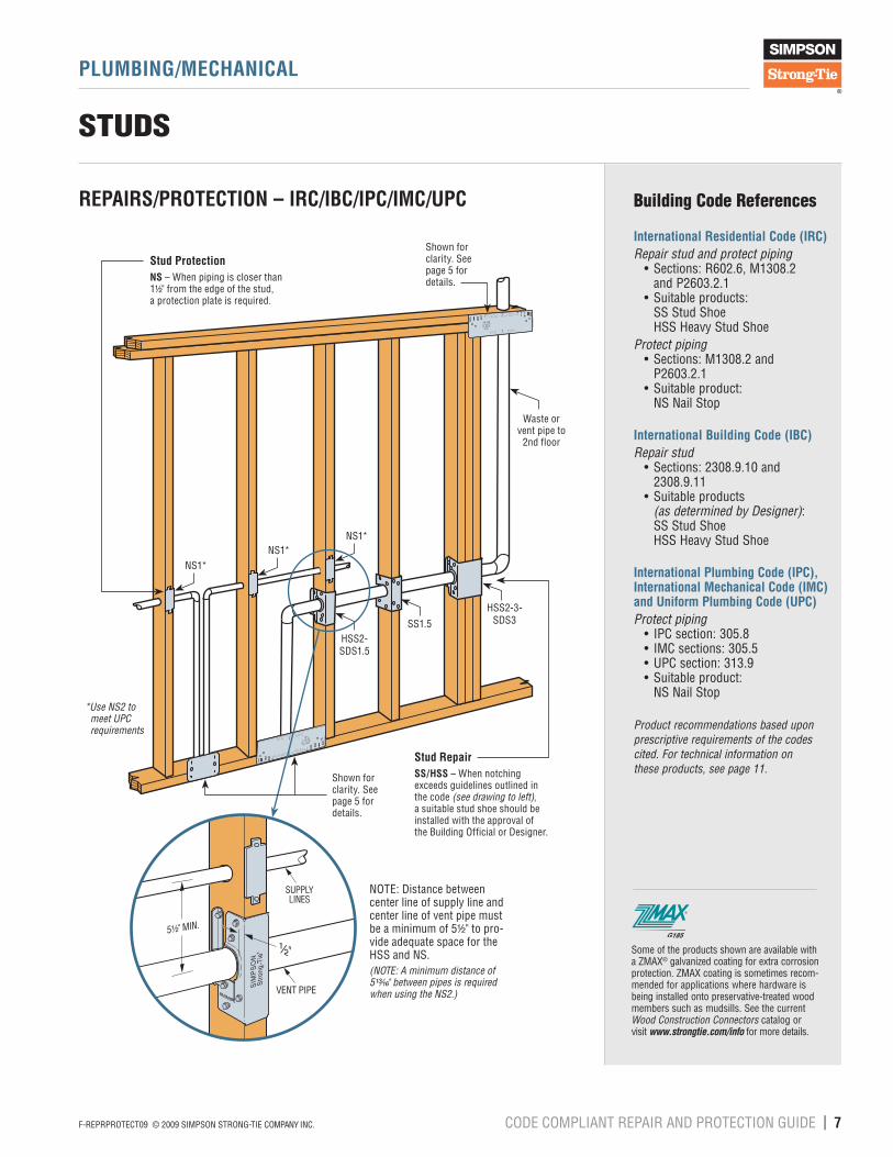
REPAIRS/PROTECTION – IRC/IBC/IPC/IMC/UPC
Building Code References
International Residential Code (IRC)Repair stud and protect piping • Sections: R602.6, M1308.2 and P2603.2.1 • Suitable products: SS Stud Shoe HSS Heavy Stud ShoeProtect piping • Sections: M1308.2 and P2603.2.1 • Suitable product: NS Nail Stop
International Building Code (IBC)Repair stud • Sections: 2308.9.10 and 2308.9.11 • Suitable products (as determined by Designer): SS Stud Shoe HSS Heavy Stud Shoe
International Plumbing Code (IPC), International Mechanical Code (IMC) and Uniform Plumbing Code (UPC) Protect piping • IPC section: 305.8 • IMC sections: 305.5 • UPC section: 313.9 • Suitable product: NS Nail Stop
Product recommendations based upon prescriptive requirements of the codes cited. For technical information on these products, see page 11.
SIM SONS r ng T ePS N5 6Z
16 Ga
S 6 6 N LS
O T P A E NS L T N
Use W n gs
s n e o i o
s & ais
ogcmfo
UE 26 NS
R I PA ITLTN
SMPON
Stog-e
SP51Z
6 Ga
UE 6 AS
FR TP PT INTLTON
e & ans
sotcomfo
U e W n gs
r g e o n o
U E 2 6 N LS
F R L P A E I S L A ON
NS1*NS1*
NS1*
HSS2-SDS1.5
SS1.5
HSS2-3-SDS3
Stud RepairSS/HSS – When notching exceeds guidelines outlined in the code (see drawing to left), a suitable stud shoe should be installed with the approval of the Building Official or Designer.
Stud ProtectionNS – When piping is closer than 1¹⁄₂" from the edge of the stud, a protection plate is required.
Waste or vent pipe to
2nd floor
NOTE: Distance between center line of supply line and center line of vent pipe must be a minimum of 5¹⁄₂" to pro-vide adequate space for the HSS and NS.(NOTE: A minimum distance of 5¹³⁄₁₆" between pipes is required when using the NS2.)
Some of the products shown are available witha ZMAX® galvanized coating for extra corrosion protection. ZMAX coating is sometimes recom-mended for applications where hardware is being installed onto preservative-treated wood members such as mudsills. See the current Wood Construction Connectors catalog or visit www.strongtie.com/info for more details.
Shown for clarity. See page 5 for details.
*Use NS2 to meet UPC requirements
Shown for clarity. See page 5 for details.
8 | CODE COMPLIANT REPAIR AND PROTECTION GUIDE F-REPRPROTECT09 © 2009 SIMPSON STRONG-TIE COMPANY INC.
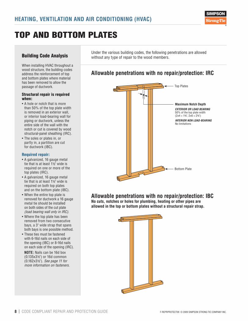
HEATING, VENTILATION AND AIR CONDITIONING (HVAC)
TOP AND BOTTOM PLATES
Building Code Analysis
When installing HVAC throughout a wood structure, the building codes address the reinforcement of top and bottom plates where material has been removed to allow the passage of ductwork.
Structural repair is required when:• A hole or notch that is more than 50% of the top plate width is removed in an exterior wall, or interior load-bearing wall for piping or ductwork, unless the entire side of the wall with the notch or cut is covered by wood structural-panel sheathing (IRC).• The soles or plates in, or partly in, a partition are cut for ductwork (IBC).
Required repair:• A galvanized, 16 gauge metal tie that is at least 1¹⁄₂" wide is required on one or more of the top plates (IRC).• A galvanized, 16 gauge metal tie that is at least 1¹⁄₂" wide is required on both top plates and on the bottom plate (IBC).• When the entire top plate is removed for ductwork a 16 gauge metal tie should be installed on both sides of the cut plate (load bearing wall only in IRC).• Where the top plate has been removed from two consecutive bays, a 3" wide strap that spans both bays is one possible method. • These ties must be fastened with 6-16d nails on each side of the opening (IBC) or 8-16d nails on each side of the opening (IRC). NOTE: Nails can be 16d box (0.135x3¹⁄₂") or 16d common (0.162x3¹⁄₂"). See page 11 for more information on fasteners.
Under the various building codes, the following penetrations are allowed without any type of repair to the wood members.
Allowable penetrations with no repair/protection: IRC
Allowable penetrations with no repair/protection: IBCNo cuts, notches or holes for plumbing, heating or other pipes are allowed in the top or bottom plates without a structural repair strap.
Maximum Notch DepthEXTERIOR OR LOAD BEARING 50% of the top plate width (2x4 = 1³⁄₄", 2x6 = 2³⁄₄")
INTERIOR NON LOAD-BEARINGNo limitations
Bottom Plate
Top Plates

F-REPRPROTECT09 © 2009 SIMPSON STRONG-TIE COMPANY INC. CODE COMPLIANT REPAIR AND PROTECTION GUIDE | 9
HEATING, VENTILATION AND AIR CONDITIONING (HVAC)
TOP AND BOTTOM PLATES
Building Code References
International Residential Code (IRC)Repair top plates • R602.6.1 • Suitable product: RPS and MSTC Repair Straps
International Building Code (IBC)Repair top and bottom plates • Section 2308.9.8 • Suitable product: RPS and MSTC Repair Straps
Product recommendations based upon prescriptive requirements of the codes cited. For technical information on these products, see page 11.
HVAC REPAIRS – IRCTop Plate RepairEXTERIOR OR LOAD BEARINGRPS28 – When more than 50% of the width of the top plate is removed, a galvanized structural repair strap that is not less than 16 gauge x 1¹⁄₂" wide is required. The strap must be installed on the upper-most plate, and fastened on either side of the cut with 8-16d nails.NON-LOAD BEARING – No repair required.
Top Plate Repair – Side-by-Side DuctworkLOAD BEARINGMSTC52 – When more than 50% of the width of the top plate is removed, a galvanized structural repair strap that is not less than 16 gauge x 1¹⁄₂" wide is required. In this application a 3" wide strap provides equivalent tension capacity as long as it is fastened on each side of the cut with 8-16d nails. NON-LOAD BEARING – No repair required.
RPS28
HVACChase inExterioror LoadBearing
Wall
MSTC52
HVACChase
(2)Adjacent
StudBays
Interior, non-load bearing walls require no structural repair.
Load Bearing Wall(with HVAC chase)
HVAC REPAIRS – IBCTop and Bottom Plate RepairRPS28 – Whenever the soles or plates are cut, a galvanized structural repair strap that is not less than 16 gauge x 1¹⁄₂" wide is required on each plate and is to be fastened with 6-16d nails on each side of the cut.
Top and Bottom Plate Repair – Two Consecutive BaysMSTC52 – Whenever the soles or plates are cut, a galvanized structural repair strap that is not less than 16 gauge x 1¹⁄₂" wide is required on each plate. In this application a 3" wide strap provides equivalent tension capacity as long as it is fastened on each side of the cut with 6-16d nails per plate.
RPS28
RPS28
HVACChase inExterioror LoadBearing
Wall
HVACChase
(2)Adjacent
StudBays
MSTC52
MSTC52
Some of the products shown are available witha ZMAX® galvanized coating for extra corrosion protection. ZMAX coating is sometimes recom-mended for applications where hardware is being installed onto preservative-treated wood members such as mudsills. See the current Wood Construction Connectors catalog or visit www.strongtie.com/info for more details.

10 | CODE COMPLIANT REPAIR AND PROTECTION GUIDE F-REPRPROTECT09 © 2009 SIMPSON STRONG-TIE COMPANY INC.
ELECTRICAL
TOP PLATE, BOTTOM PLATE AND STUDS
Building Code Analysis
When installing electrical wiring throughout a wood structure the building codes require protection of the wiring to prevent damage.
Protection of wiring within the wall is required when:• A hole is closer than 1¹⁄₄" to the edge of a wood member (IRC, N.E.C.).
Required protection:• A 16 gauge protective steel plate that covers the area of the wiring (IRC, N.E.C.).
While the codes do not specifically address top or bottom plate repair for electrical applications, Simpson Strong-Tie recommends that the guidelines shown on page 5 be considered. This will help ensure that plates perform as intended after electrical is installed.
Building Code References
International Residential Code (IRC) and National Electric Code (NEC)Protect wiring • IRC Table E3702.1 • NEC Section 300.4 • Suitable product: NS Nail Stops
Product recommendations based upon prescriptive requirements of the codes cited. For technical information on these products, see page 11.
Allowable penetrations with no repair/protection
Electrical Protection
NS1
NS2
NS1
NS2
Stud and Plate ProtectionNS – When a hole is closer than 1¹⁄₄" from the edge of a wood member (due to diameter or placement) a protective steel plate is required.
Some of the products shown are available witha ZMAX® galvanized coating for extra corrosion protection. ZMAX coating is sometimes recom-mended for applications where hardware is being installed onto preservative-treated wood members such as mudsills. See the current Wood Construction Connectors catalog or visit www.strongtie.com/info for more details.
Maximum hole diameter in studs and plates to maintain 1¹⁄₄"distance:2x4 = 1"2x6 = 3"

F-REPRPROTECT09 © 2009 SIMPSON STRONG-TIE COMPANY INC. CODE COMPLIANT REPAIR AND PROTECTION GUIDE | 11
TECHNICAL INFORMATION
Some of the products shown above are available with a ZMAX® galvanized coating for extra corrosion protection. ZMAX coating is recommended for applications where hardware is being installed onto preservative-treated wood members such as mudsills. See the current Wood Construction Connectors catalog or visit www.strongtie.com/info for more details.
PSPN Repair and Shield Plates
1. Unless otherwise noted “16d” refers to 16d common nails. To meet the prescriptive IRC requirement 16d box nails (0.135" dia. x 3¹⁄₂") may be used. Allowable tension load is 0.75 of table loads when installed with 16d box nails. 10dx1¹⁄₂ (0.148" dia. x 1¹⁄₂") may be used to meet the 2009 IRC prescriptive requirement.2. NAILS: 16d common = 0.162" dia. x 3¹⁄₂" long.
Model No. GaDimensions Fasteners
(Total)
Allowable Tension Load
DF/SP
Allowable Tension Load
SPF/HFW L (160) (160)
PSPN58Z 16 5 8 2-8d — —
PSPN516Z 16 5 16⁵⁄₁₆12-16d 1365 118016-16d 1820 1575
PSPN58Z
USE 16 16d NAILSFOR TOP P ATE NSTALLAT ON
Use & War ingsst ong ie com/ n o
Use & Warnngstrngtecom/nfo
USE 12-1d NALSFOR SILL PLATE INSTALATION
PSPN516Z
RPS Repair StrapCODES: ICC-ESR-2608; City of L.A. RR25281; Florida FL 10864
1. To meet the prescriptive IRC requirement 16d box nails (0.135" dia. x 3¹⁄₂") may be used. Allowable tension load is 0.75 of table loads when installed with 16d box nails. 10dx1¹⁄₂ (0.148" dia. x 1¹⁄₂") may be used to meet the 2009 IRC prescriptive requirement.2. Install with 12 fasteners to meet IBC requirement, and 16 to meet IRC.3. NAILS: 16d common = 0.162" dia. x 3¹⁄₂" long.
ModelNo. Ga
Dimensions NotchWidth
Fasteners(Total)
Allowable TensionLoads (DF/SP)
Allowable TensionLoads (SPF/HF)
W L Nails (160) (160)RPS18
16
1¹⁄₂ 18⁵⁄₁₆ ≤ 5¹⁄₂" 12-16d 1380 1190
RPS22 1¹⁄₂ 22⁵⁄₁₆≤ 5¹⁄₂"
12-16d 1380 11901¹⁄₂ 22⁵⁄₁₆ 16-16d 1805 1585
RPS28 1¹⁄₂ 28⁵⁄₁₆≤ 12"
12-16d 1380 11901¹⁄₂ 28⁵⁄₁₆ 16-16d 1805 1585
MSTC Repair StrapCODES: ICC-ESR-2523; City of L.A. RR25713; Florida FL 10852
ModelNo. Ga
Dimensions Fasteners(Total)
Allowable TensionLoads (DF/SP)
Allowable TensionLoads (SPF/HF)
W L Nails (160) (160)
MSTC52 16 3 52¹⁄₄12-16d sinkers 1150 99516-16d sinkers 1535 1330
HSS/SS Stud Shoes
1. Roof loads are 125% of floor loads unless limited by other criteria. Floor loads may be adjusted for other load durations according to the code, provided they do not exceed roof loads. Tension loads may not be adjusted.2. NAILS: 10d = 0.148" dia. x 3" long, 10dx1¹⁄₂ = 0.148" dia. x 1¹⁄₂" long.
ModelNo. Ga Stud
Size Fasteners
Allowable Loads1
DF/SPCompression
TensionFloor (100) Roof (125)
SS1.5 16 2x 12-10dx1¹⁄₂ 500 500 —SS2.5 16 3x 12-10dx1¹⁄₂ 500 500 —SS3 16 2-2x 12-10d 665 785 —SS4.5 16 3-2x 14-10d 665 785 —HSS2-SDS1.5 16 2x 12-SDS ¹⁄₄"x1¹⁄₂" 1200 1200 1000HSS2-2-SDS3 16 2-2x 12-SDS ¹⁄₄"x3" 1200 1200 1000HSS2-3-SDS3 16 3-2x 12-SDS ¹⁄₄"x3" 1000 1000 970HSS4-SDS3 16 4x 12-SDS ¹⁄₄"x3" 1200 1200 1000
U.S. Patent6,176,057
HSS SS
CODES: ICC-ESR-2608; Florida FL 10864
1. OPTIONAL NAILS: 8d = 0.131" dia. x 2¹⁄₂" long.
Model No. Ga W LNS1 16 1¹⁄₂ 3NS2 16 1¹⁄₂ 6
NS Nail Stops
NS
RPS
MSTC
1. To meet the prescriptive IRC requirement 16d common or 16d box nails (0.135" dia. x 3¹⁄₂") may be used. Allowable tension load is 0.88 of table loads when installed with 16d box nails. Install 8 nails at each end of strap.
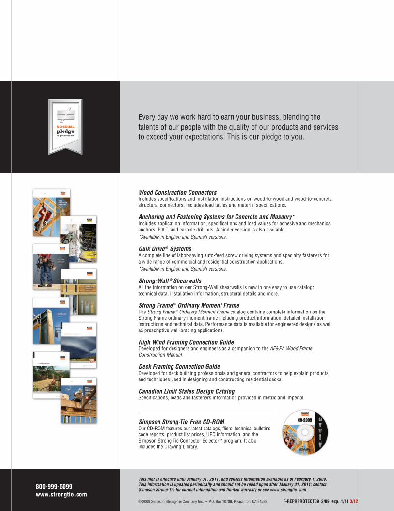
Every day we work hard to earn your business, blending thetalents of our people with the quality of our products and servicesto exceed your expectations. This is our pledge to you.
Wood Construction ConnectorsIncludes specifications and installation instructions on wood-to-wood and wood-to-concrete structural connectors. Includes load tables and material specifications.
Anchoring and Fastening Systems for Concrete and Masonry*Includes application information, specifications and load values for adhesive and mechanical anchors, P.A.T. and carbide drill bits. A binder version is also available.*Available in English and Spanish versions.
Quik Drive® SystemsA complete line of labor-saving auto-feed screw driving systems and specialty fasteners for a wide range of commercial and residential construction applications.*Available in English and Spanish versions.
Strong-Wall ® ShearwallsAll the information on our Strong-Wall shearwalls is now in one easy to use catalog: technical data, installation information, structural details and more.
Strong Frame™ Ordinary Moment FrameThe Strong Frame™ Ordinary Moment Frame catalog contains complete information on the Strong Frame ordinary moment frame including product information, detailed installation instructions and technical data. Performance data is available for engineered designs as well as prescriptive wall-bracing applications.
High Wind Framing Connection GuideDeveloped for designers and engineers as a companion to the AF&PA Wood Frame Construction Manual.
Deck Framing Connection GuideDeveloped for deck building professionals and general contractors to help explain products and techniques used in designing and constructing residential decks.
Canadian Limit States Design CatalogSpecifications, loads and fasteners information provided in metric and imperial.
Simpson Strong-Tie Free CD-ROMOur CD-ROM features our latest catalogs, fliers, technical bulletins, code reports, product list prices, UPC information, and the Simpson Strong-Tie Connector Selector™ program. It also includes the Drawing Library.
800-999-5099www.strongtie.com
This fl ier is effective until January 31, 2011, and refl ects information available as of February 1, 2009. This information is updated periodically and should not be relied upon after January 31, 2011; contact Simpson Strong-Tie for current information and limited warranty or see www.strongtie.com.
© 2009 Simpson Strong-Tie Company Inc. • P.O. Box 10789, Pleasanton, CA 94588 F-REPRPROTECT09 2/09 exp. 1/11 3/12