Embed Size (px)
Citation preview

PROJECT REPORT
DIGITAL CODE LOCK

Table of contents
1. Abstract
2. Block diagram
3. Block diagram description
3.1 Keypad
3.2 Microcontroller
3.3 Relay
3.4 LCD
4. Circuit Diagram
5. Circuit Description
6. List of components
7. Software tools
8. Results and conclusions
9. References

List of figures and tablesFigure 1: Block diagram
Figure 2: Circuit diagram
Table 1: List of components
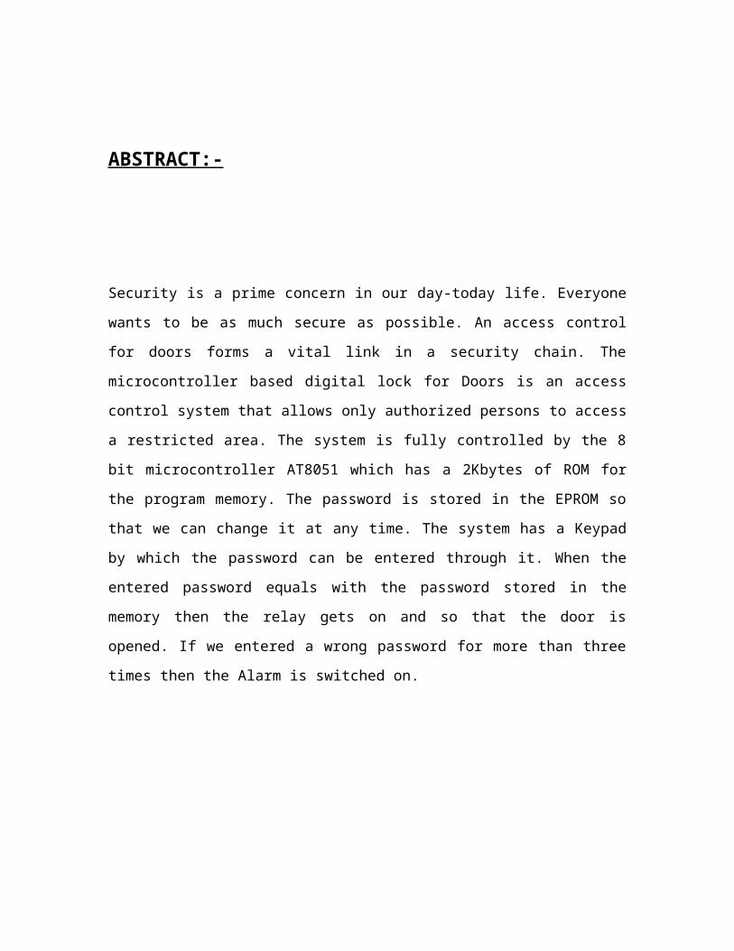
ABSTRACT:-
Security is a prime concern in our day-today life. Everyone wants to be as much secure as
possible. An access control for doors forms a vital link in a security chain. The
microcontroller based digital lock for Doors is an access control system that allows only
authorized persons to access a restricted area. The system is fully controlled by the 8 bit
microcontroller AT8051 which has a 2Kbytes of ROM for the program memory. The
password is stored in the EPROM so that we can change it at any time. The system has a
Keypad by which the password can be entered through it. When the entered password
equals with the password stored in the memory then the relay gets on and so that the door
is opened. If we entered a wrong password for more than three times then the Alarm is
switched on.

BLOCK DIAGRAM:-

BLOCK DESCRIPTION:-
1. KEYPAD:- The input is taken from a 4x3 Keypad .Keypad has 12 keys (4x3)
starting from 1,2,3,4,5,6,7,8,9,*,0,# (please see the schematic for layout).
Numeric keys are used for entering numbers. '*' is used as the Cancel key and '#'
is used as the Enter key.
2. MICROCONTROLLER: - The controller is the heart of the circuit. It is used to
do all the programming of the circuit.
3. RELAY: - It is used as a switch. It functions according to the controller output.
4. LCD: - The output is displayed over the LCD Screen.

CIRCUIT DIAGRAM:-
CIRCUIT DESCRIPTION:-
1. KEYPAD MATRIX:-
Keypad has 12 keys (4x3) starting from 1,2,3,4,5,6,7,8,9,*,0,# (please see the schematic
for layout). Numeric keys are used for entering numbers. '*' is used as the Cancel key and
'#' is used as the Enter key.
2. MICROCONTROLLER:-
The controller is used to do all the programming. It has the following features:-
It provides many functions (CPU, RAM, ROM, I/O, interrupt logic, timer, etc.) in
a single package
8-bit ALU, Accumulator and 8-bit Registers; hence it is an 8-bit microcontroller
8-bit data bus - It can access 8 bits of data in one operation
16-bit address bus - It can access 216 memory locations - 64 KB (65536 locations)
each of RAM and ROM
On-chip RAM - 128 bytes (data memory)
On-chip ROM - 4 Kbytes (program memory)
Four byte bi-directional input/output port
UART (serial port)
Two 16-bit Counter/timers

Two-level interrupt priority
Power saving mode
A particularly useful feature of the 8051 core is the inclusion of a Boolean processing
engine which allows bit-level Boolean logic operations to be carried out directly and
efficiently on internal registers and RAM. This feature helped cement the 8051's
popularity in industrial control applications. Another valued feature is that it has four
separate register sets, which can be used to greatly reduce interrupt latency compared to
the more common method of storing interrupt context on a stack.
The 8051 UARTs make it simple to use the chip as a serial communications interface.
External pins can be configured to connect to internal shift registers in a variety of ways,
and the internal timers can also be used, allowing serial communications in a number of
modes, both synchronous and asynchronous. Some modes allow communications with no
external components. A mode compatible with an RS-485 multi-point communications

environment is achievable, but the 8051's real strength is fitting in with existing ad-hoc
protocols (e.g., when controlling serial-controlled devices).
Once a UART, and a timer if necessary, have been configured, the programmer needs
only to write a simple interrupt routine to refill the send shift register whenever the last
bit is shifted out by the UART and/or empty the full receive shift register (copy the data
somewhere else). The main program then performs serial reads and writes simply by
reading and writing 8-bit data to stacks.
8051 based microcontrollers typically include one or two UARTs, two or three timers,
128 or 256 bytes of internal data RAM (16 bytes of which are bit-addressable), up to 128
bytes of I/O, 512 bytes to 64 kB of internal program memory, and sometimes a quantity
of extended data RAM (ERAM) located in the external data space. The original 8051
core ran at 12 clock cycles per machine cycle, with most instructions executing in one or
two machine cycles. With a 12 MHz clock frequency, the 8051 could thus execute 1
million one-cycle instructions per second or 500,000 two-cycle instructions per second.
Enhanced 8051 cores are now commonly used which run at six, four, two, or even one
clock per machine cycle, and have clock frequencies of up to 100 MHz, and are thus
capable of an even greater number of instructions per second. All SILabs, some Dallas
and a few Atmel devices have single cycle cores.
Common features included in modern 8051 based microcontrollers include built-in reset
timers with brown-out detection, on-chip oscillators, self-programmable Flash ROM
program memory, boot loader code in ROM, EEPROM non-volatile data storage, I²C,
SPI, and USB host interfaces, CAN or LIN bus, PWM generators, analog comparators,
A/D and D/A converters, RTCs, extra counters and timers, in-circuit debugging facilities,
more interrupt sources, and extra power saving modes.
3. RELAY:-
A relay is an electrically operated switch. Many relays use an electromagnet to operate a
switching mechanism, but other operating principles are also used. Relays find

applications where it is necessary to control a circuit by a low-power signal, or where
several circuits must be controlled by one signal. The first relays were used in long
distance telegraph circuits, repeating the signal coming in from one circuit and re-
transmitting it to another. Relays found extensive use in telephone exchanges and early
computers to perform logical operations. A type of relay that can handle the high power
required to directly drive an electric motor is called a contactor. Solid-state relays control
power circuits with no moving parts, instead using a semiconductor device triggered by
light to perform switching. Relays with calibrated operating characteristics and
sometimes multiple operating coils are used to protect electrical circuits from overload or
faults; in modern electric power systems these functions are performed by digital
instruments still called "protection relays".

A relay is an electrically operated switch.
Current flowing through the coil of the relay
creates a magnetic field which attracts a lever
and changes the switch contacts. The coil
current can be on or off so relays have two
switch positions and most have double throw
(changeover) switch contacts as shown in the
diagram.
Relays allow one circuit to switch a second
circuit which can be completely separate from
the first. For example a low voltage battery
circuit can use a relay to switch a 230V AC
mains circuit. There is no electrical connection
inside the relay between the two circuits, the link
is magnetic and mechanical.
The coil of a relay passes a relatively large
current, typically 30mA for a 12V relay, but it
can be as much as 100mA for relays designed to
operate from lower voltages. Most ICs (chips)
cannot provide this current and a transistor is
usually used to amplify the small IC current to
the larger value required for the relay coil. The
maximum output current for the popular 555
timer IC is 200mA so these devices can supply relay coils directly without amplification.
Relays are usually SPDT or DPDT but they can have many more sets of switch contacts,
for example relays with 4 sets of changeover contacts are readily available. For further
information about switch contacts and the terms used to describe them please see the
page on switches.
Circuit symbol for a relay
Relays
Relay showing coil and switch contacts

Most relays are designed for PCB mounting but you can solder wires directly to the pins
providing you take care to avoid melting the plastic case of the relay.
The supplier's catalogue should show you the relay's connections. The coil will be
obvious and it may be connected either way round. Relay coils produce brief high voltage
'spikes' when they are switched off and this can destroy transistors and ICs in the circuit.
To prevent damage you must connect a protection diode across the relay coil.
The animated picture shows a working relay with its coil and switch contacts. You can
see a lever on the left being attracted by magnetism when the coil is switched on. This
lever moves the switch contacts. There is one set of contacts (SPDT) in the foreground
and another behind them, making the relay DPDT.
The relay's switch connections are usually labeled COM, NC and NO:
COM = Common, always connect to this; it is the moving part of the switch.
NC = Normally Closed, COM is connected to this when the relay coil is off.
NO = Normally Open, COM is connected to this when the relay coil is on.
Connect to COM and NO if you want the switched circuit to be on when the
relay coil is on.
Connect to COM and NC if you want the switched circuit to be on when the
relay coil is off.
4. LCD:-
Liquid Crystal Displays (LCD)
These components are “specialized” for being used with the microcontrollers, which
means that they cannot be activated by standard IC circuits. They are used for writing
different messages on a miniature LCD.

Amodel described here is for its low price and great possibilities most frequently used in
practice. It is based on the HD44780 microcontroller (Hitachi) and can display messages
in two lines with 16 characters each . It displays all letters of alphabet, greek letters,
punctuation marks, mathematical symbols etc. In addition, it is possible to display
symbols that user makes up on its own. Automatic shifting message on display (shift left
and right), appearance of the pointer, backlight etc. are considered as useful
characteristics.
Pins Functions
There are pins along one side of the small printed board used for connection to the
microcontroller. There are total of 14 pins marked with numbers (16 in case the
background light is built in). Their function is described in the table bellow:
FunctionPin
NumberName
Logic
StateDescription
Ground 1 Vss - 0V
Power supply 2 Vdd - +5V
Contrast 3 Vee - 0 - Vdd
Control of
operating 4 RS0
1
D0 – D7 are interpreted as
commands
D0 – D7 are interpreted as data
5 R/W 0
1
Write data (from controller to
LCD)

Read data (from LCD to
controller)
6 E
0
1
From 1 to
0
Access to LCD disabled
Normal operating
Data/commands are transferred to
LCD
Data / commands
7 D0 0/1 Bit 0 LSB
8 D1 0/1 Bit 1
9 D2 0/1 Bit 2
10 D3 0/1 Bit 3
11 D4 0/1 Bit 4
12 D5 0/1 Bit 5
13 D6 0/1 Bit 6
14 D7 0/1 Bit 7 MSB
LCD screen
LCD screen consists of two lines with 16 characters each. Each character consists of 5x8
or 5x11 dot matrix. This book covers 5x8 character display because it is commonly used.
Contrast on display depends on the power supply voltage and whether messages are
displayed in one or two lines. For that reason, variable voltage 0-Vdd is applied on pin

marked as Vee. Trimmer potentiometer is usually used for that purpose. Some versions of
displays have built in backlight (blue or green diodes). When used during operating, a
resistor for current limitation should be used (like with any LE diode).
If there are no characters on display or all of them are dimmed upon the display is on, the
first thing that should be done is to check the potentiometer for contrast regulation. Is it
properly adjusted? Same applies in case the operation mode is changed (writing in one or
two lines).
LCD Memory
There are three memory blocks inside the display:
DDRAM Display Data RAM
CGRAM Character Generator RAM
CGROM Character Generator ROM
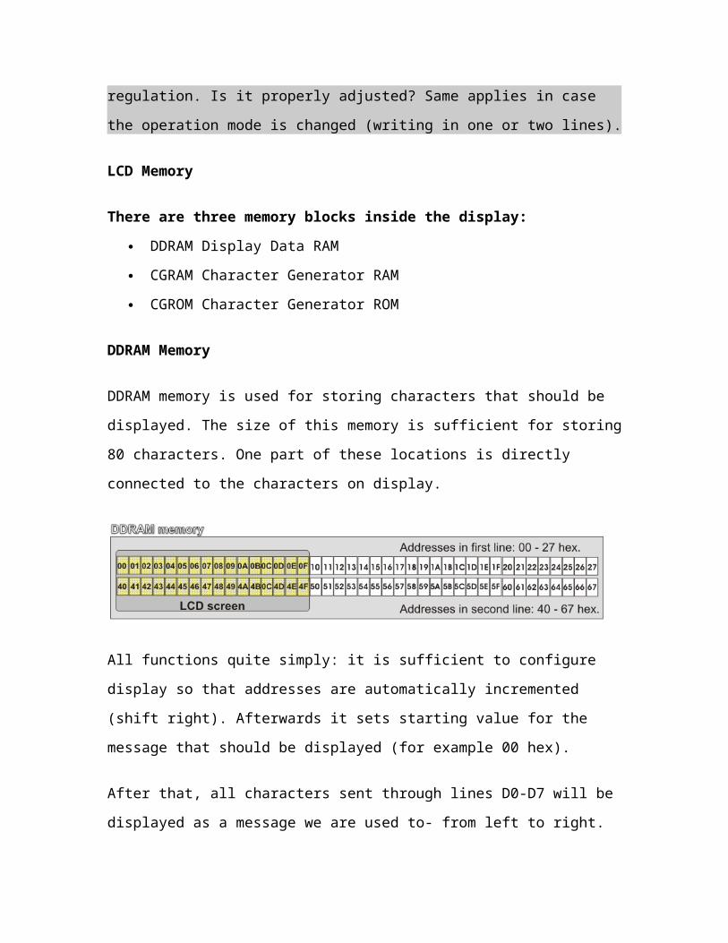
DDRAM Memory

DDRAM memory is used for storing characters that should be displayed. The size of this
memory is sufficient for storing 80 characters. One part of these locations is directly
connected to the characters on display.
All functions quite simply: it is sufficient to configure display so that addresses are
automatically incremented (shift right). Afterwards it sets starting value for the message
that should be displayed (for example 00 hex).
After that, all characters sent through lines D0-D7 will be displayed as a message we are
used to- from left to right. In this case, displaying starts from the first character in the first
line on display since the address is 00 hex. If more than 16 characters are sent, they all
will be also memorized but not visible. In order to display them, a shift command should
be used. Virtually, everything looks as if LCD display is a “window” which moves left-
right over memory locations with characters. In reality, that is how the affect of message
“moving” on the screen is obtained (from left to right or vice versa).
If cursor is on, it will appear at location which is currently addressed. In other words,
characters will appear at cursor’s position while the cursor is automatically moved to the
next addressed location.
Since this is a sort of RAM memory, data can be written to and read from it.
Disadvantage is that the contents will be lost forever upon the power is off.
CGROM Memory
A “map” with all characters that can be displayed are written by default. Each character
has corresponding location.


Addresses of CGROM memory locations match standard ASCII values of characters. It
means that if in a program being currently executed by the microcontroller is written
“send letter P to port”, the binary value 0101 0000 will appear on the port. This value is
ASCII equivalent to the letter P. When this binary number is sent to LCD, a symbol
stored on 0101 0000 location in CGROM will be displayed. In other words, the letter “P”

will be displayed . This applies to all alphabet letters (upper- and lowercase), but not to
numbers!
If one carefully looks at the “map” with characters in this memory, it can be seen that
addresses of all digits are “shifted” by 48 in comparison to the values of these digits
(address of the digit 0 is 48, of digit 1 is 49, of digit 2 is 50 etc.). For that reason and in
order to display digits correctly, each of them needs to be added a decimal number 48
prior to being sent to LCD.
Since the time the first computer was made, it recognizes numbers but not letters. It
means that on sending any character from keyboard to PC, from PC to printer or from
microcontroller to other computer, through connection line are actually sent binary
numbers instead of characters . A table that links all standard symbols and their number
equivalents is called ASCII code.
CGRAM memory
Beside being able to display all standard characters, the LCD can display symbols that
user defines on its own. It enables displaying cyrilic fonts as well as many other symbols
which fit to the frame of 5x8 dots size. RAM memory (CGRAM) in size of 64 bytes
enables the above.
The size of registers of this memory is a standard one (8 bits), but only 5 lower bits are in
use. Logic one (1) in every register represents a dimmed dot, while 8 locations considered
jointly represent one character. It is best illustrated on the figure below:

Symbols are usually defined at the beginning of a program by simple writing zeros and
units to registers of CGRAM memory so that they form desirable shapes. In order to
display them it is sufficient to specify their address. Pay attention to the first columns in
CGROM map of characters- these are not addresses of RAM memory but symbols which
are discussed here. In this example, “display 0” means - display “č”, “display 1” means -
display “ž” etc.
LCD Basic Commands
All data transferred to LCD through outputs D0-D7 will be interpreted as commands or
as data, which depends on logic state on pin RS:
RS = 1 - Bits D0 - D7 are addresses of characters that should be displayed. Built in
processor addresses built in “map of characters” and displays corresponding symbols.
Displaying position is determined by DDRAM address. This address is either previously
defined or the address of previously transferred character is automatically incremented.
RS = 0 - Bits D0 - D7 are commands which determine display mode. List of commands
which LCD “recognizes” are given in the table below:
Command RS RW D7 D6 D5 D4 D3 D2 D1 D0Execution
Time
Clear display 0 0 0 0 0 0 0 0 0 1 1.64mS
Cursor home 0 0 0 0 0 0 0 0 1 x 1.64mS
Entry mode set 0 0 0 0 0 0 0 1 I/D S 40uS
Display on/off control 0 0 0 0 0 0 1 D U B 40uS
Cursor/Display Shift 0 0 0 0 0 1 D/C R/L x x 40uS
Function set 0 0 0 0 1 DL N F x x 40uS
Set CGRAM address 0 0 0 1 CGRAM address 40uS
Set DDRAM address 0 0 1 DDRAM address 40uS
Read “BUSY” flag (BF) 0 1 BF DDRAM address -
Write to CGRAM or
DDRAM1 0 D7 D6 D5 D4 D3 D2 D1 D0 40uS
Read from CGRAM or
DDRAM1 1 D7 D6 D5 D4 D3 D2 D1 D0 40uS
I/D 1 = Increment (by 1) R/L 1 = Shift right
0 = Decrement (by 1) 0 = Shift left
S 1 = Display shift on DL 1 = 8-bit interface
0 = Display shift off 0 = 4-bit interface
D 1 = Display on N 1 = Display in two lines
0 = Display off 0 = Display in one line
U 1 = Cursor on F 1 = Character format 5x10 dots
0 = Cursor off 0 = Character format 5x7 dots
B 1 = Cursor blink on D/C 1 = Display shift
0 = Cursor blink off 0 = Cursor shift
What is Busy flag ?
Comparing to the microcontroller, LCD is an extremly slow component. Because of that
It was necessary to provide a signal which will indicate that display is ready to receive a
new data or a command following the previous one has been executed. That signal is
called busy flag and can be read from line D7. When the bit BF is cleared (BF=0),
display is ready to receive.
LCD Connection
Depending on how many lines are used for connection to the microcontroller, there are 8-
bit and 4-bit LCD modes. The appropriate mode is determined at the beginning of the
process in a phase called “initialization”. In the first case, the data are transferred through
outputs D0-D7 as it has been already explained. In case of 4-bit LED mode, for the sake

of saving valuable I/O pins of the microcontroller, there are only 4 higher bits (D4-D7)
used for communication, while other may be left unconnected. Consequently, each data is
sent to LCD in two steps: four higher bits are sent first (that normally would be sent
through lines D4-D7), four lower bits are sent afterwards. With the help of initialization,
LCD will correctly connect and interprete each data received. Besides, with regards to the
fact that data are rarely read from LCD (data mainly are transferred from microcontroller
to LCD) one more I/O pin may be saved by simple connecting R/W pin to the Ground.
Such saving has its price. Even though message displaying will be normally performed, it
will not be possible to read from busy flag since it is not possible to read from display.
Luckily, solution is simple. It is sufficient to give LCD enough time to perform its task
upon sending every character or command. Since execution of the slowest command is
approximately 1.64mS, it will be quite enough to wait for approximately 2mS.

LCD Initialization
Once the power supply is turned on, LCD is automatically cleared. This process lasts for
approximately 15mS. After that, display is ready to operate. The mode of operating is set
by default. This means that:
1. Display is cleared
2. Mode
o DL = 1 Communication through 8-bit interface
o N = 0 Messages are displayed in one line
o F = 0 Character font 5 x 8 dots
3. Display/Cursor on/off
o D = 0 Display off
o U = 0 Cursor off
o B = 0 Cursor blink off
4. Character entry
o ID = 1 Addresses on display are automatically incremented by 1
o S = 0 Display shift off
Automatic reset is mainly performed without any problems. Mainly but not always! If for
any reason power supply voltage does not reach full value in the course of 10mS, display
will start perform completely unpredictably. If voltage supply unit can not meet this
condition or if it is needed to provide completely safe operating, the process of
initialization by which a new reset enabling display to operate normally must be applied.
Algorithm according to the initialization is being performed depends on whether
connection to the microcontroller is through 4- or 8-bit interface. All left over to be done
after that is to give basic commands and of course- to display messages...
Refer to the Figure below for the procedure on 8-bit initialization:

It is not a mistake!
In algorithm on figure, the same value is being transmitted three times in a row.
In case of 4-bit initialization, the procedure is as follows:


POWER SUPPLY:-
Power supply is used to drive the circuit. Inappropriate voltage will damage the entire
circuitry therefore it constitutes a very important part of the circuit.
Every electronic circuit requires power for its operation. Every function simple or
complex is controlled by the power supply. Even a little variation in voltage can damage
all the circuitry. So power supply is of prime importance in all the circuits. The power
supply which we get is a.c. operating at 220Volts.But as our electronic circuits work only
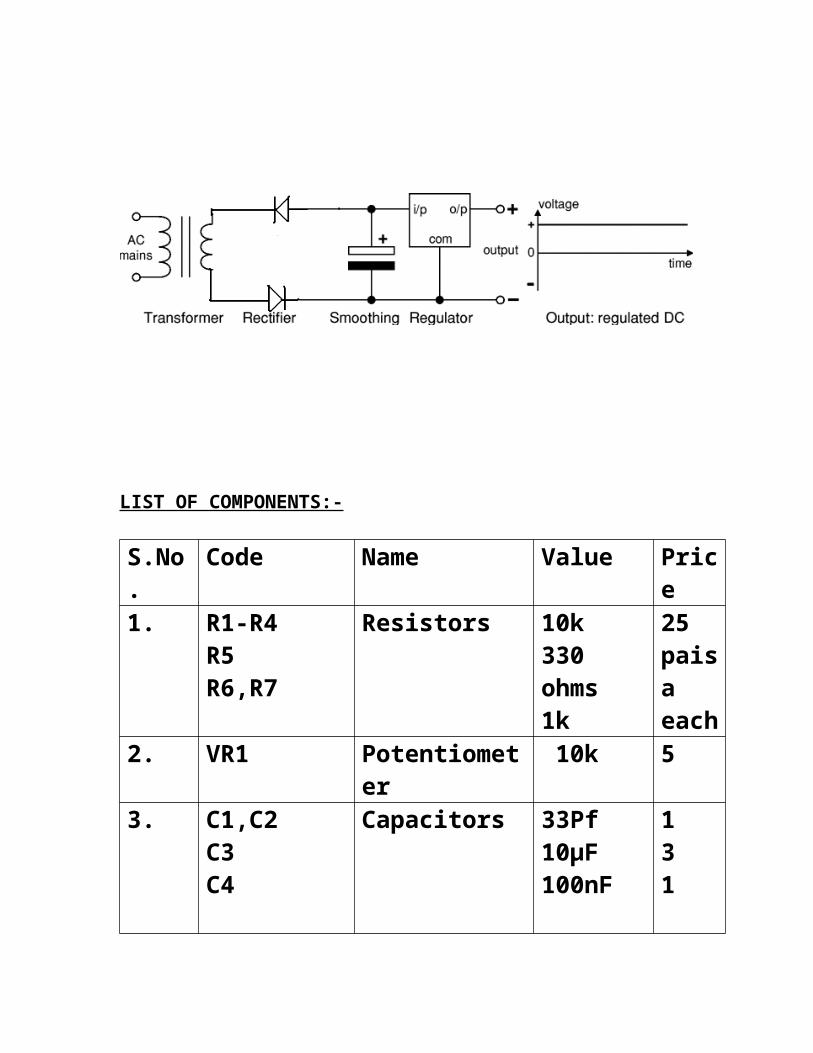
on d.c. therefore; we cannot employ direct usage of supply which we get. In order to
overcome this, we require various process namely transformation, rectification,
smoothing or filtering and regulation. These entire process using bridge rectifiers are
illustrated below:

Power supply is used to drive the circuit. Inappropriate voltage will damage the entire
circuitry therefore it constitutes a very important part of the circuit.
Every electronic circuit requires power for its operation. Every function simple or
complex is controlled by the power supply. Even a little variation in voltage can damage
all the circuitry. So power supply is of prime importance in all the circuits. The power
supply which we get is a.c. operating at 220Volts.But as our electronic circuits work only
on d.c. therefore; we cannot employ direct usage of supply which we get : . In order to
overcome this, we require various process namely transformation, rectification,
smoothing or filtering and regulation. All these process using bridge rectifier are
illustrated below
Now let’s study the detail of all the processes step by step.
TRANSFORMATION:-
As already discussed the supply which we get is 220V A.C. supply. In order to decrease
the magnitude of the voltage we make use of step down transformer. This transformer has

more windings in the primary coil than in the secondary coil. So the voltage output at the
secondary is an A.C. supply with magnitude less than 220V as shown below:
RECTIFICATION:-
As all the electronic circuits work on DC therefore this low voltage A.C. cannot be
directly fed to our circuit. Thus a process of rectification is required. In this process, A.C.
voltage is converted into D.C. voltage using two semiconductor rectifying diodes as
shown below:
Now as the two diodes D1 and D2 are connected in the opposite manner. Therefore one
of the diode gets forward biased during the positive half of the a.c input and other gets
forward biased during the negative half of the a.c. input. Thus during the positive half
cycle rectification takes place through diode D1(diode D2 being reverse biased, cannot
rectify) and during the negative half cycle, the rectification takes place through the diode

D2(diode D1 being reverse biased, cannot rectify). But as at least one of the diode always
remain in the conducting mode therefore both the halves of the a.c. input gets rectified
and hence the name full wave rectifier.
SMOOTHING/FILTRATION
The output of the rectification process is a varying D.C. As the D.C. waveform cannot be
varying so it means that rectification is not 100% efficient due to which there is still some
component of the input A.C. present in the D.C. voltage which is responsible for the
variation. So in order to remove this A.C. component we require filtration or smoothing
of the signal. This can be done using an electrolytic capacitor of 2200uf. As the capacitor
offers infinite impedance to the D.C. signal and Zero impedance to the A.C. signal
therefore, it allows the A.C. component to pass through and blocks the D.C. component.
This means it will filter out the D.C. component from the input signal. Thus the output of
the process will be a pure D.C. supply as shown below:
Now there is still some variation indicating that output D.C. voltage is not having
constant magnitude. This is due to the capacitor used for filtration. Its time of charging
and discharging are not equal due to which the filtration is not up to the mark. For
making the output voltage assume a constant value we need a voltage regulator.
REGULATION:-
Voltage regulator is used for this purpose mainly from the series of 78- - of the transistor.
For getting the constant output of 5 volts we make use of 7805 voltage regulator. This
process takes place as shown below:
This completes all the processes. Now we have a constant D.C. supply with us which can
be fed to any electronic circuit without any problem

LIST OF COMPONENTS:-
S.No. Code Name Value Price
1. R1-R4R5R6,R7
Resistors 10k330 ohms1k
25 paisa each
2. VR1 Potentiometer 10k 53. C1,C2
C3C4
Capacitors 33Pf10µF100nF
131
4. IC1LCD1,LED2LCD
MicrocontrollerLEDLCD
AT80515mm16*2
55110
5. Q1J1J3
CrystalConnectorconnector
12MHz3 Pin4 pin
1010

Software tools:-
Orcad for circuit designing .We first make schematic in it. This in turn creates lay out of
PCB.
Keil for compiling. Microcontroller understands hex files. But as hex files are very
complicated therefore we make use of the software keil. Programming in keil makes use
of C or Assembly language which are easily programmable. Keil on its own converts
these files to hex files.
Proload After the formation of hex file we need to insert this hex file into the micro
controller so that it executes the program written in the keil. For this purpose we make
use of proload.
Soldering
Soldering is a process in which two or more metal items are joined together by melting
and flowing a filler metal into the joint, the filler metal having a relatively low melting
point. Soft soldering is characterized by the melting point of the filler metal, which is
below 400 °C (800 °F). The filler metal used in the process is called solder.
Soldering is distinguished from brazing by use of a lower melting-temperature filler
metal; it is distinguished from welding by the base metals not being melted during the
joining process. In a soldering process, heat is applied to the parts to be joined, causing
the solder to melt and be drawn into the joint by capillary action and to bond to the
materials to be joined by wetting action. After the metal cools, the resulting joints are not
as strong as the base metal, but have adequate strength, electrical conductivity, and water-
tightness for many uses. Soldering is an ancient technique mentioned in the Bible and
there is evidence that it was employed up to 5000 years ago in Mesopotamia.

Applications
One of the most frequent applications of soldering is assembling electronic components
to printed circuit boards (PCBs). Another common application is making permanent but
reversible connections between copper pipes in plumbing systems. Joints in sheet metal
objects such as food cans, roof flashing, rain gutters and automobile radiators have also
historically been soldered, and occasionally still are. Jewelry components are assembled
and repaired by soldering. Small mechanical parts are often soldered as well. Soldering is
also used to join lead came and copper foil in stained glass work. Soldering can also be
used to affect a semi-permanent patch for a leak in a container cooking vessel.
Solders
Soldering filler materials are available in many different alloys for differing applications.
In electronics assembly, the eutectic alloy of 63% tin and 37% lead (or 60/40, which is
almost identical in performance to the eutectic) has been the alloy of choice. Other alloys
are used for plumbing, mechanical assembly, and other applications.
A eutectic formulation has several advantages for soldering; chief among these is the
coincidence of the liquidus and solidus temperatures, i.e. the absence of a plastic phase.
This allows for quicker wetting out as the solder heats up, and quicker setup as the solder
cools. A non-eutectic formulation must remain still as the temperature drops through the
liquidus and solidus temperatures. Any differential movement during the plastic phase
may result in cracks, giving an unreliable joint. Additionally, a eutectic formulation has
the lowest possible melting point, which minimizes heat stress on electronic components
during soldering.
Lead-free solders are suggested anywhere children may come into contact (since children
are likely to place things into their mouths), or for outdoor use where rain and other

precipitation may wash the lead into the groundwater. Common solder alloys are
mixtures of tin and lead, respectively:
63/37: melts at 183 °C (361.4 °F) (eutectic: the only mixture that melts at a point,
instead of over a range)
60/40: melts between 183–190 °C (361–374 °F)
50/50: melts between 185–215 °C (365–419 °F)
Lead-free solder alloys melt around 250 °C (482 °F), depending on their composition.
For environmental reasons, 'no-lead' solders are becoming more widely used.
Unfortunately most 'no-lead' solders are not eutectic formulations, making it more
difficult to create reliable joints with them. See complete discussion below; see also
RoHS.
Other common solders include low-temperature formulations (often containing bismuth),
which are often used to join previously-soldered assemblies without un-soldering earlier
connections, and high-temperature formulations (usually containing silver) which are
used for high-temperature operation or for first assembly of items which must not
become unsoldered during subsequent operations. Specialty alloys are available with
properties such as higher strength, better electrical conductivity and higher corrosion
resistance.
Flux
In high-temperature metal joining processes (welding, brazing and soldering), the
primary purpose of flux is to prevent oxidation of the base and filler materials. Tin-lead
solder, for example, attaches very well to copper, but poorly to the various oxides of
copper, which form quickly at soldering temperatures. Flux is a substance which is nearly
inert at room temperature, but which becomes strongly reducing at elevated temperatures,
preventing the formation of metal oxides. Secondarily, flux acts as a wetting agent in the
soldering process, reducing the surface tension of the molten solder and causing it to
better wet out the parts to be joined.

Fluxes currently available include water-soluble fluxes (no VOC's required for removal)
and 'no-clean' fluxes which are mild enough to not require removal at all. Performance of
the flux needs to be carefully evaluated; a very mild 'no-clean' flux might be perfectly
acceptable for production equipment, but not give adequate performance for a poorly-
controlled hand-soldering operation.
Traditional rosin fluxes are available in non-activated (R), mildly activated (RMA) and
activated (RA) formulations. RA and RMA fluxes contain rosin combined with an
activating agent, typically an acid, which increases the wettability of metals to which it is
applied by removing existing oxides. The residue resulting from the use of RA flux is
corrosive and must be cleaned off the piece being soldered. RMA flux is formulated to
result in a residue which is not significantly corrosive, with cleaning being preferred but
optional.
Basic soldering techniques
Methods
Soldering operations can be performed with hand tools, one joint at a time, or en masse
on a production line. Hand soldering is typically performed with a soldering iron,
soldering gun, or a torch, or occasionally a hot-air pencil. Sheetmetal work was
traditionally done with "soldering coppers" directly heated by a flame, with sufficient
stored heat in the mass of the soldering copper to complete a joint; torches or electrically-
heated soldering irons are more convenient. All soldered joints require the same elements
of cleaning of the metal parts to be joined, fitting up the joint, heating the parts, applying
flux, applying the filler, removing heat and holding the assembly still until the filler metal
has completely solidified. Depending on the nature of flux material used, cleaning of the
joints may be required after they have cooled.
The distinction between soldering and brazing is arbitrary, based on the melting
temperature of the filler material. A temperature of 450 °C is usually used as a practical
cut-off. Different equipment and/or fixturing is usually required since (for instance) a
soldering iron generally cannot achieve high enough temperatures for brazing. Practically

speaking there is a significant difference between the two processes—brazing fillers have
far more structural strength than solders, and are formulated for this as opposed to
maximum electrical conductivity. Brazed connections are often as strong or nearly as
strong as the parts they connect, even at elevated temperatures.
"Hard soldering" or "silver soldering" (performed with high-temperature solder
containing up to 40% silver) is also often a form of brazing, since it involves filler
materials with melting points in the vicinity of, or in excess of, 450 °C. Although the
term "silver soldering" is used much more often than "silver brazing", it may be
technically incorrect depending on the exact melting point of the filler in use. In silver
soldering ("hard soldering"), the goal is generally to give a beautiful, structurally sound
joint, especially in the field of jewelry. Thus, the temperatures involved, and the usual use
of a torch rather than an iron, would seem to indicate that the process should be referred
to as "brazing" rather than "soldering", but the endurance of the "soldering" apellation
serves to indicate the arbitrary nature of the distinction (and the level of confusion)
between the two processes.
Induction soldering is a process which is similar to brazing. The source of heat in
induction soldering is induction heating by high-frequency AC current. Generally copper
coils are used for the induction heating. This induces currents in the part being soldered.
The coils are usually made of copper or a copper base alloy. The copper rings can be
made to fit the part needed to be soldered for precision in the work piece. Induction
soldering is a process in which a filler metal (solder) is placed between the faying
surfaces of (to be joined) metals. The filler metal in this process is melted at a fairly low
temperature. Fluxes are a common use in induction soldering. This is a process which is
particularly suitable for soldering continuously. The process is usually done with coils
that wrap around a cylinder/pipe that needs to be soldered. Some metals are easier to
solder than others. Copper, silver, and gold are easy. Iron and nickel are found to be more
difficult. Because of their thin, strong oxide films, stainless steel and aluminum are a
little more difficult. Titanium, magnesium, cast irons, steels, ceramics, and graphites can
be soldered but it involves a process similar to joining carbides. They are first plated with
a suitable metallic element that induces interfacial bonding.

Desoldering and resoldering
Used solder contains some of the dissolved base metals and is unsuitable for reuse in
making new joints. Once the solder's capacity for the base metal has been achieved it will
no longer properly bond with the base metal, usually resulting in a brittle cold solder joint
with a crystalline appearance.
It is good practice to remove solder from a joint prior to resoldering—desoldering braids
or vacuum desoldering equipment (solder suckers) can be used. Desoldering wicks
contain plenty of flux that will lift the contamination from the copper trace and any
device leads that are present. This will leave a bright, shiny, clean junction to be
resoldered.
The lower melting point of solder means it can be melted away from the base metal,
leaving it mostly intact though the outer layer will be "tinned" with solder. Flux will
remain which can easily be removed by abrasive or chemical processes. This tinned layer
will allow solder to flow into a new joint, resulting in a new joint, as well as making the
new solder flow very quickly and easily.
Common tools
Hand-soldering tools include the electric soldering iron, which has a variety of tips
available ranging from blunt to very fine to chisel heads for hot-cutting plastics, and the
soldering gun, which typically provides more power, giving faster heat-up and allowing
larger parts to be soldered. Hot-air guns and pencils allow rework of component packages
which cannot easily be performed with irons and guns.
Soldering torches are a type of soldering device that uses a flame rather than a soldering
iron tip to heat solder. Soldering torches are often powered by butane[3] and are available

in sizes ranging from very small butane/oxygen units suitable for very fine but high-
temperature jewelry work, to full-size oxy-fuel torches suitable for much larger work
such as copper piping.
A soldering copper is a tool with a large copper head and a long handle, which is heated
in a blacksmith's forge fire, and used to apply heat to sheet metal for soldering. Soldering
coppers are sometimes used in auto bodywork, although body solder has been mostly
superseded by non-metallic fillers.
Toaster ovens and hand held infrared lights have been used to reproduce production
processes on a much smaller scale.
Bristle brushes are usually used to apply plumbing paste flux. For electronic work, flux-
core solder is generally used, but additional flux may be used from a flux pen or
dispensed from a small bottle with a syringe-like needle.
Wire brush, wire wool and emery cloth are commonly used to prepare plumbing joints
for connection. Electronic joints rarely require mechanical cleaning.
For PCB assembly and rework, alcohol and acetone are commonly used with cotton
swabs or bristle brushes to remove flux residue. A heavy rag is usually used to remove
flux from a plumbing joint before it cools and hardens. A fiberglass brush can also be
used.
For electronic work, solder wick and vacuum-operated "solder sucker" are used to undo
solder connections.
A heat sink, such as a crocodile clips, can also be used to prevent damaging heat-
sensitive components while soldering.

Soldering Tools
The only tools that are essential to solder are a soldering iron and some solder. There are, however,
lots of soldering accessories available (see soldering accessories for more information).
Different soldering jobs will need different tools, and different temperatures too. For circuit board work
you will need a finer tip, a lower temperature and finer grade solder. You may also want to use a
magnifying glass. Audio connectors such as XLR's will require a larger tip, higher temperature and
thicker solder. Clamps and holders are also handy when soldering audio cables.
Soldering Irons
There are several things to consider when choosing a soldering iron.
Wattage
adjustable or fixed temperature
power source (electric or gas)
portable or bench use
I do not recommend soldering guns, as these have no temperature control and can get too hot. This
can result in damage to circuit boards, melt cable insulation, and even damage connectors.

Wattage
It is important to realise that higher wattage does not necessarily mean hotter soldering iron. Higher
wattage irons just have more power available to cope with bigger joints. A low wattage iron may not
keep its temperature on a big joint, as it can loose heat faster than it can reheat itself. Therefore,
smaller joints such as circuit boards require a lesser wattage iron - around 15-30 watts will be fine.
Audio connectors need something bigger - I recommend 40 watts at least.
Temperature
There are a lot of cheap, low watt irons with no temperature control
available. Most of these are fine for basic soldering, but if you are going
to be doing a lot you may want to consider a variable temperature
soldering iron. Some of these simply have a boost button on the handle,
which is useful with larger joints, others have a thermostatic control so you can vary the heat of the tip.
If you have a temperature controlled iron you should start at about 315-345°C (600-650°F). You may
want to increase this however - I prefer about 700-750°F. Use a temperature that will allow you to
complete a joint in 1 to 3 seconds.
Power
Most soldering irons are mains powered - either 110/230v AC, or
benchtop soldering stations which transform down to low voltage DC.
Also available are battery and gas powered. These are great for the
toolbox, but you'll want a plug in one for your bench. Gas soldering irons
loose their heat in windy outside conditions more easily that a good high
wattage mains powered iron.
Portability
Most cheaper soldering irons will need to plug into the mains. This is fine a lot of the time, but if there
is no mains socket around, you will need another solution. Gas and battery soldering irons are the
answer here. They are totally portable and can be taken and used almost anywhere. They may not be
as efficient at heating as a good high wattage iron, but they can get you out of a lot of hassle at times.
If you have a bench setup, you should consider using a soldering
station. These usually have a soldering iron and desoldering iron with
heatproof stands, variable heat, and a place for a cleaning pad. A good

solder station will be reliable, accurate with its temperature, and with a range of tips handy it can
perform any soldering task you attempt with it.
Solder
The most commonly used type of solder is rosin core. The rosin is flux,
which cleans as you solder. The other type of solder is acid core and
unless you are experienced at soldering, you should stick to rosin core
solder. Acid core solder can be tricky, and better avoided for the
beginner.
Rosin core solder comes in three main types - 50/50, 60/40 and 63/37. These numbers
represent the amount of tin and lead are present in the solder,as shown below.
Solder Type % Tin % Lead Melting Temp (°F)
50/50 50 50 425
60/40 60 40 371
63/37 63 37 361
Any general purpose rosin core solder will be fine.
Soldering Accessories
Soldering Iron Tips
Try to use the right size tip whenever you can. Smaller wires and circuit
boards require small fine tips, and mic cable onto an XLR would need a
larger tip. You can get pointed tips, or flat tipped ones (sometimes called
'spade tips'). If you have a solder station with a desolderer, you will also
want a range of desoldering tips and cleaners.
Soldering Iron Stands
These are handy to use if you are doing several or more joints. It is a
heat resistant cradle for your iron to sit in, so you don't have to lie it
down on the bench while it is hot. It really is essential if you are planning
to do a lot of bench soldering as it is only a matter of time before you
burn something (probably your elbow resting on the hot tip) if you don't
use one.
Clamps
I strongly recommend clamps of some sort. Trying to hold your soldering
iron, the solder, and the wire is tricky enough, but when you have to
hold the connector as well it is almost impossible. The are however,
adjustable clamps that can be manipulated to hold both the connector
and the wire in place so you still have two free hands to apply the heat and the solder. These are
cheap items, and I know mine have paid for themselves many times over.
Magnifying glass
If you are doing work on PCBs (printed circuit boards) you may need to
get a magnifying glass. This will help you see the tracks on the PCB,
and unless you have exceptional sight, small chip resistors are pretty
difficult to solder on well without a magnifying glass. Once again, they
are not expensive, and some clamps come with one that can mount on
the clamp stand.
Solder Wick
Solder wick is a mesh the you lie on a joint and heat. When it heats up it
also melts the solder which is drawn out of the joint. It is usually used for
cleaning up solder from tracks on a circuit board, but you will need a
solder sucker to clean out the holes in the circuit board. Place the wick
on the solder you want to remove then put your soldering iron on top of
the wick. The wick will heat up, then the solder will melt and flow away from the joint and into wick.
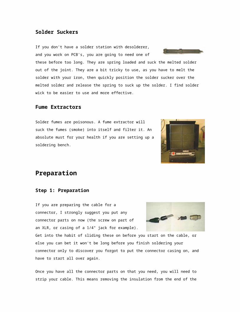
Solder Suckers
If you don't have a solder station with desolderer, and you work on
PCB's, you are going to need one of these before too long. They are
spring loaded and suck the melted solder out of the joint. They are a bit

tricky to use, as you have to melt the solder with your iron, then quickly position the solder sucker over
the melted solder and release the spring to suck up the solder. I find solder wick to be easier to use
and more effective.
Fume Extractors
Solder fumes are poisonous. A fume extractor will suck the fumes
(smoke) into itself and filter it. An absolute must for your health if you
are setting up a soldering bench.
Preparation
Step 1: Preparation
If you are preparing the cable for a connector, I strongly
suggest you put any connector parts on now (the screw on part
of an XLR, or casing of a 1/4" jack for example). Get into the
habit of sliding these on before you start on the cable, or else
you can bet it won't be long before you finish soldering your
connector only to discover you forgot to put the connector casing on, and have to start all over again.
Once you have all the connector parts on that you need, you will need to strip your cable. This means
removing the insulation from the end of the wire and exposing the copper core. You can either use a
wire stripper, side cutters, or a knife to do this.
The obvious tool to choose to strip a wire would be......a wire
stripper. There are many types of wire stripper, and most of
them work the same. You simply put the wire in, and squeeze it
and pull the end bit off. It will cut to a preset depth, and if you
have chosen the right depth it will cut the insulation off perfectly. It is possible to choose the wrong
depth and cut too deeply, or too shallow, but they are very easy to use.
On the other hand, some people (myself included) prefer to use a knife or side cutters. I use side
cutters for small cable and a Stanley knife for bigger cables...and although I have a couple of wire
strippers, I haven't used them for years. This may seem odd, but I've got my side cutters and knife with
me anyway, and they do the job fine.

If you are using side cutters (as shown here),
position them about 10mm (1/2 inch) from the
end, and gently squeeze the cutters into the
insulation to pierce it, but not far enough to
cut the copper strands of the core. Open the
cutters slightly so you can turn the wire and
pierce the rest of the insulation. You may have to do this a few times to cut through all of the
insulation, but it is better to cut too shallow and have to turn and cut again rather than cut the core and
have to start again. Now you should be able to slide the insulation off with your cutters, or pull it off
with your fingers. This may sound a tedious method, but in no time at all you will be able to do it in two
cuts and a flick of the cutters.
I won't explain how I use a knife to do larger cable, as I'd hate someone to slice a finger or thumb open
following my instructions. Using a sharp blade like that certainly does have it's risks, so stick with wire
cutters or side cutters if you are at all unsure.
If your connector has been used before, make sure you remove any
remnants of wire and solder from the contacts. Do this by putting the tip of
your soldering iron into the hole and flicking the solder out when it has
melted. Common Sense Alert! Please be careful when you flick melted
solder...flick it away from you.
Tinning
Step 2: Tinning
Whatever it is you are soldering, you should 'tin' both contacts
before you attempt to solder them. This coats or fills the wires
or connector contacts with solder so you can easily melt them
together.
To tin a wire, apply the tip of your iron to the wire for a second
or two, then apply the solder to the wire. The solder should flow
freely onto the wire and coat it (if it's stranded wire the solder should flow into it, and fill the wire). You
may need to snip the end off afterwards, particularly if you have put a little too much solder on and it
has formed a little ball at the end of the wire.

Be careful not to overheat the wire, as the insulation will start to
melt. On cheaper cable the insulation can 'shrink back' if
heated too much, and expose more copper core that you
intended. You can cut the wire back after you have tinned it,
but it's best simply not to over heat it.
The larger the copper core, the longer it will take to heat up enough to draw the solder in, so use a
higher temperature soldering iron for larger cables if you can.
To tin a contact on an audio XLR connector, hold the iron on
the outside of the the contact for a second or two, then apply
the solder into the cavity of the contact. Once again, the solder
should flow freely and fill the contact. Connectors such as jacks
have contacts that are just holes in a flat part of the connector.
To tin these you put your iron on it, and apply the solder to
where the iron is touching. The solder should flow and cover
the hole.
Once you have tinned both parts, you are ready to solder them together.
Soldering
Step 3: Soldering
This step can often be the easiest when soldering audio
cables.

You simply need to place your soldering iron onto the contact to melt the solder.
When the solder in the contact melts, slide the wire into the contact.
Remove the iron and hold the wire still while the solder solidifies again.
You will see the solder 'set' as it goes hard.
This should all take around 1-3 seconds.
A good solder joint will be smooth and shiny.
If the joint is dull and crinkly, the wire probably moved
during soldering.
If you have taken too long it will have have solder
spikes.
If it does not go so well, you may find the insulation has melted, or there is too much stripped wire
showing. If this is the case, you should desolder the joint and start again.
Cleaning Your Soldering Iron
You should clean your tip after each use. There are many cleaning solutions and the cheapest (and
some say best) is a damp sponge. Just rub the soldering iron tip on it after each solder.
Another option is to use tip cleaner. This comes in a little pot that you
push the tip into. This works well if your tip hasn't been cleaned for a
while. It does create a lot of smoke, so it is better not to let the tip get so
dirty that you need to use tip cleaner.
Some solder stations come with a little pad at the base of the holder. If
you have one of these, you should get into the habit of wiping the tip on
the pad each time you apply solder with it.
If you need to clean solder off a circuit board, solder wick is what you
need. You place the wick on the joint or track you want to clean up, and

apply your soldering iron on top. The solder melts and is drawn into the wick. If there is a lot of solder
the wick will fill up, so gently pull the wick through the joint and your iron, and the solder will flow into it
as it passes.
Tips and Tricks
1. Melted solder flows towards heat.
2. Most beginning solderers tend to use too much solder and heat the joint for too long.
3. Don't move the joint until the solder has cooled.
4. Keep your iron tip clean.
5. Use the proper type of iron and tip size.
Troubleshooting
If either of the parts you are soldering is dirty or greasy, the solder won't take (or 'stick') to it. Desolder
the joint and clean the parts before trying again.
Another reason the solder won't take is that it may not be the right sort of metal. For example you
cannot solder aluminium with lead/tin solder.
If the joint has been moved during soldering, it may look grainy or dull. It may also look like this if the
joint was not heated properly while soldering.
If the joint was overheated the solder will have formed a spike and there will be burnt flux residue.
Power supply
Power supply
The term power supply is more commonly abbreviated to PSU, this will be used from
hereon in.
Telecommunications equipment is designed to operate on voltages lower than the
domestic Mains voltage. In order to reduce this voltage a PSU is used.
To provide a useable low voltage the PSU needs to do a number of things:-

Reduce the Mains AC (Alternating current) voltage to a lower level.
Convert this lower voltage from AC to DC (Direct current)
Regulate the DC output to compensate for varying load (current demand)
Provide protection against excessive input/output voltages.
Reduction of AC Mains
This is achieved by using a device known as a Transformer an electromagnetic device
consisting of an ferrous iron core which has a large number of turns of wire wound
around it, known as the Primary Winding
The ends of these turns of wire being connected to the input voltage (in this case Mains
AC).
A second number of turns of wire are wound around the Primary Winding, this set
being known as the Secondary Winding.
The difference between the number of turns provides us with a way of reducing (in our
case) a high AC voltage to a lower one.
Conversion of AC to DC
To convert our now low AC voltage to DC we use a Rectifier Diode connected to the
Secondary Winding.
This is a silicon diode, which has operation analogous to a bicycle tyre valve (as the
valve only allows air to flow into the tyre, the diode only allows current to flow in one
direction)
As our low AC voltage will be working at a frequency of 50Hz (Mains AC frequency) it
is desirable to reduce the inherent hum on this to a lower level.
This is achieved by a technique known as Smoothing (“Ironing” out the bumps in the
AC).
A simple way to reduce the hum is to use Full Wave Rectification.
Today this is usually done by four diodes in a bridge configuration known as a Bridge
Rectifier. (This can be four individual diodes or a dedicated self contained package)

Regulation of Output Voltage
The Electrolytic Capacitor is a device capable of storing energy the amount of energy
and the time it remains stored depending on the value.
In a simple PSU the easiest way to provide regulation to compensate for varying load
conditions is to use a pair of relatively high value Electrolytic Capacitors.
Their values in this case being in the region of 470uF to 2000uF depending on the
application and the amount of current required from the output of the unit.
One of these capacitors is connected across the DC output of the rectifier diode(s) or
bridge, this capacitor also providing an extra degree of smoothing the output waveform.
The second capacitor is connected via a low value, medium to high wattage resistor,
which assists in limiting the current demand.
Protection against excessive voltages
In a simple PSU the easiest way to do this is by providing fuses at the input to the
transformer, generally in the live side of the mains supply, also at the DC outputs.
In the event of an excessive input voltage, or excessive current being drawn from the
output, one of these fuses should normally blow protecting the PSU and the equipment
connected to it.
The transformer may also be fitted with an internal or external thermal fuse, which will
open if the transformer becomes hot due to the aforementioned conditions.

Transformers
A "transformer" takes one voltage and changes it into another.
What is a transformer, and why should I care?
A "transformer" changes one voltage to another. This attribute is useful in
many ways.
A transformer doesn't change power levels. If you put 100 Watts into a
transformer, 100 Watts come out the other end. [Actually, there are minor
losses in the transformer because nothing in the real world is 100% perfect.
But transformers come pretty darn close; perhaps 95% efficient.]
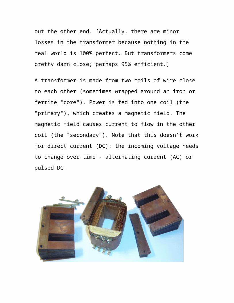
A transformer is made from two coils of wire close to each other (sometimes
wrapped around an iron or ferrite "core"). Power is fed into one coil (the
"primary"), which creates a magnetic field. The magnetic field causes
current to flow in the other coil (the "secondary"). Note that this doesn't
work for direct current (DC): the incoming voltage needs to change over
time - alternating current (AC) or pulsed DC.

Iron core
The number of times the wires are wrapped around the core ("turns") is very
important and determines how the transformer changes the voltage.
If the primary has fewer turns than the secondary, you have a step-up
transformer that increases the voltage.
If the primary has more turns than the secondary, you have a step-
down transformer that reduces the voltage.
If the primary has the same number of turns as the secondary, the
outgoing voltage will be the same as what comes in. This is the case
for an isolation transformer.
In certain exceptional cases, one large coil of wire can serve as both
primary and secondary. This is the case with variable auto-
transformers and xenon strobe trigger transformers.

Types of transformers
In general, transformers are used for two purposes: signal matching and
power supplies.
Power Transformers
Power transformers are used to convert from one voltage to another, at
significant power levels.
Step-up transformers

A "step-up transformer" allows a device that requires a high voltage power
supply to operate from a lower voltage source. The transformer takes in the
low voltage at a high current and puts out the high voltage at a low current.
Examples:
You are a Swiss visiting the U.S.A., and want to operate your
220VAC shaver off of the available 110 VAC.
The CRT display tube of your computer monitor requires thousands of
volts, but must run off of 220 VAC from the wall.

Step-down transformers
A "step-down transformer" allows a device that requires a low voltage
power supply to operate from a higher voltage. The transformer takes in the
high voltage at a low current and puts out a low voltage at a high current.
Examples:
Your Mailbu-brand landscape lights run on 12VAC, but you plug
them into the 220 VAC line.
Your doorbell doesn't need batteries. It runs on 220 VAC, converted
to 12VAC.

In many cases, step-down transformers take the form of wall warts.
Isolation transformers
An "isolation transformer" does not raise or lower a voltage; whatever
voltage comes in is what goes out. An isolation transformer prevents current

from flowing directly from one side to the other. This usually serves as a
safety device to prevent electrocution.
Variable auto-transformers
A "variable auto-transformer" (variac) can act like a step-up transformer or
step-down transformer. It has a big knob on top that allows you to dial in
whatever output voltage you want.
This page from the All Electronics catalog (#103, Winter 2003) shows some
variacs.
WARNING: A variable auto-transformer does not provide isolation from
line current. For that you need an isolation transformer.
Inverters

An "inverter" takes a DC power source and boosts it up to a higher voltage.
The most common type of inverter takes power from an automobile and
cranks out 220 VAC to run appliances and power tools. Inverters are also
used to operate fluorescent lamps from battery power.
Technically, an inverter isn't a transformer; it contains a transformer (and
lots of other stuff).
Signal Transformers
"Signal transformers" also take one thing in and transform it to another thing
out. But in this case, the power levels are low, and the transformed thing
carries some type of information signal.
In most cases, these transformers are thought of as impedance matching.
Rectifier
What is a Rectifier?
A rectifier changes alternating current into direct current. This process is called
rectification. The three main types of rectifier are the half-wave, full-wave, and bridge. A
rectifier is the opposite of an inverter, which changes direct current into alternating
current.

Half-Wave Rectifier
The simplest type is the half-wave rectifier, which can be made with just one diode.
When the voltage of the alternating current is positive, the diode becomes forward-biased
and current flows through it. When the voltage is negative, the diode is reverse-biased
and the current stops. The result is a clipped copy of the alternating current waveform
with only positive voltage, and an average voltage that is one third of the peak input
voltage. This pulsating direct current is adequate for some components, but others require
a more steady current. This requires a full-wave rectifier that can convert both parts of the
cycle to positive voltage.

Full-Wave Rectifier
The full-wave rectifier is essentially two half-wave rectifiers, and can be made with two
diodes and an earthed center tap on the transformer. The positive voltage half of the cycle
flows through one diode, and the negative half flows through the other. The center tap
allows the circuit to be completed because current can not flow through the other diode.
The result is still a pulsating direct current but with just over half the input peak voltage,
and double the frequency.
Bridge Rectifier
The bridge rectifier, also called a diode bridge, consists of four diodes connected together
in a square. Two diodes are connected at their anodes, and the other two are connected at
their cathodes. These form the rectified output terminals. The remaining ends are joined
to form two input terminals. It it usually packaged as one component with four terminals.
The bridge rectifier allows for full-wave rectification without the need for an earthed
center tap on the transformer.

Smoothing
Even the bridge rectifier has some variation in it's output voltage, so a filter is required to
smooth out this ripple. A capacitor connected across the output terminals acts as a basic
filter by storing energy during the peak voltage, and releasing it when the voltage falls.
This removes most of the ripple but does not result in a steady voltage. A choke and
second capacitor are usually added to further smooth the ripple.
Rectifier Uses
Rectifiers are used mostly in power adapters and alternators to convert alternating current
to direct current. They are also used in radios to demodulate signals from the antenna.

Resistors
Example: Circuit symbol:
Function
Resistors restrict the flow of electric current, for example a resistor is placed in
series with a light-emitting diode (LED) to limit the current passing through the
LED.
Connecting and soldering
Resistors may be connected either way round. They are not damaged by heat when
soldering.
Resistor values - the resistor colour code
Resistance is measured in ohms, the symbol for ohm is an omega .
1 is quite small so resistor values are often given in k and M .
1 k = 1000 1 M = 1000000 .
Resistor values are normally shown using coloured bands.
Each colour represents a number as shown in the table.

Most resistors have 4 bands:
The first band gives the first digit.
The second band gives the second digit.
The third band indicates the number of zeros.
The fourth band is used to shows the tolerance
(precision) of the resistor, this may be ignored for
almost all circuits but further details are given below.
This resistor has red (2), violet (7), yellow (4 zeros) and
gold bands.
So its value is 270000 = 270 k .
On circuit diagrams the is usually omitted and the value is written 270K.
Small value resistors (less than 10 ohm)
The standard colour code cannot show values of less than 10 . To show these
small values two special colours are used for the third band: gold which means
The Resistor
Colour Code
Colour Number
Black 0
Brown 1
Red 2
Orange 3
Yellow 4
Green 5
Blue 6
Violet 7
Grey 8
White 9

× 0.1 and silver which means × 0.01. The first and second bands represent the
digits as normal.
For example:
red, violet, gold bands represent 27 × 0.1 = 2.7
green, blue, silver bands represent 56 × 0.01 = 0.56
Tolerance of resistors (fourth band of colour code)
The tolerance of a resistor is shown by the fourth band of the colour code.
Tolerance is the precision of the resistor and it is given as a percentage. For
example a 390 resistor with a tolerance of ±10% will have a value within 10% of
390 , between 390 - 39 = 351 and 390 + 39 = 429 (39 is 10% of 390).
A special colour code is used for the fourth band tolerance:
silver ±10%, gold ±5%, red ±2%, brown ±1%.
If no fourth band is shown the tolerance is ±20%.
Tolerance may be ignored for almost all circuits because precise resistor values are
rarely required.
Resistor shorthand:
Resistor values are often written on circuit diagrams using a code system which
avoids using a decimal point because it is easy to miss the small dot. Instead the
letters R, K and M are used in place of the decimal point. To read the code: replace
the letter with a decimal point, then multiply the value by 1000 if the letter was K,
or 1000000 if the letter was M. The letter R means multiply by 1.
For example:

560R means 560
2K7 means 2.7 k = 2700
39K means 39 k
1M0 means 1.0 M = 1000 k
Resistors in Series and Parallel:
Power Ratings of Resistors
Electrical energy is converted to heat when current flows
through a resistor. Usually the effect is negligible, but if the
resistance is low (or the voltage across the resistor high) a
large current may pass making the resistor become noticeably
warm. The resistor must be able to withstand the heating
effect and resistors have power ratings to show this.
Power ratings of resistors are rarely quoted in parts lists
because for most circuits the standard power ratings of
0.25W or 0.5W are suitable. For the rare cases where a
higher power is required it should be clearly specified in the
parts list, these will be circuits using low value resistors (less than about 300 ) or
high voltages (more than 15V).
The power, P, developed in a resistor is given by:
P = I² × R
or
P = V² / R
where: P = power developed in the resistor in watts (W)
I = current through the resistor in amps (A)
R = resistance of the resistor in ohms ( )
V = voltage across the resistor in volts (V)
Examples:
High power resistors
(5W top, 25W bottom)

A 470 resistor with 10V across it, needs a power rating P = V²/R = 10²/470 =
0.21W.
In this case a standard 0.25W resistor would be suitable.
A 27 resistor with 10V across it, needs a power rating P = V²/R = 10²/27 =
3.7W.
A high power resistor with a rating of 5W would be suitable.
Variable Resistors
Construction
Variable resistors consist of a resistance track with
connections at both ends and a wiper which moves along
the track as you turn the spindle. The track may be made
from carbon, cermet (ceramic and metal mixture) or a coil
of wire (for low resistances). The track is usually rotary but
straight track versions, usually called sliders, are also
available.
Variable resistors may be used as a rheostat with two connections (the wiper and
just one end of the track) or as a potentiometer with all three connections in use.
Miniature versions called presets are made for setting up circuits which will not
require further adjustment.
Standard Variable Resistor

Variable resistors are often called potentiometers in books and catalogues. They
are specified by their maximum resistance, linear or logarithmic track, and their
physical size. The standard spindle diameter is 6mm.
The resistance and type of track are marked on the body:
4K7 LIN means 4.7 k linear track. 1M LOG means 1 M logarithmic track.
Some variable resistors are designed to be mounted directly on the circuit board,
but most are for mounting through a hole drilled in the case containing the circuit
with stranded
wire connecting their terminals to the circuit board.
Resistor color code
Example 1
(Brown=1),(Black=0),(Orange=3)
10 x 103 = 10k ohm
Tolerance(Gold) = ±5%

Example 2
(Yellow=4),(Violet=7),(Black=0),(Red=2)
470 x 102 = 47k ohm
Tolerance(Brown) = ±1%

Capacitors
The capacitor's function is to store electricity, or electrical energy.
The capacitor also functions as a filter, passing alternating current (AC), and
blocking direct current (DC).
This symbol is used to indicate a capacitor in a circuit diagram.
The capacitor is constructed with two electrode plates facing eachother, but
separated by an insulator.
When DC voltage is applied to the
capacitor, an electric charge is stored on
each electrode. While the capacitor is
charging up, current flows. The current
will stop flowing when the capacitor has
fully charged.
When a circuit tester, such as an analog meter set to measure resistance, is
connected to a 10 microfarad (µF) electrolytic capacitor, a current will flow, but
only for a moment. You can confirm that the meter's needle moves off of zero,
but returns to zero right away.
When you connect the meter's probes to the capacitor in reverse, you will note
that current once again flows for a moment. Once again, when the capacitor has
fully charged, the current stops flowing. So the capacitor can be used as a filter
that blocks DC current. (A "DC cut" filter.)
However, in the case of alternating current, the current will be allowed to pass.
Alternating current is similar to repeatedly switching the test meter's probes back
and forth on the capacitor. Current flows every time the probes are switched.
The value of a capacitor (the capacitance), is designated in units called the
Farad(F).
The capacitance of a capacitor is generally very small, so units such as the
microfarad ( 10-6F ), nanofarad ( 10-9F ), and picofarad (10-12F ) are used.
Recently, an new capacitor with very high capacitance has been developed. The
Electric Double Layer capacitor has capacitance designated in Farad units. These
are known as "Super Capacitors."
Sometimes, a three-digit code is used to indicate the value of a capacitor. There
are two ways in which the capacitance can be written. One uses letters and
numbers, the other uses only numbers. In either case, there are only three
characters used. [10n] and [103] denote the same value of capacitance. The
method used differs depending on the capacitor supplier. In the case that the
value is displayed with the three-digit code, the 1st and 2nd digits from the left
show the 1st figure and the 2nd figure, and the 3rd digit is a multiplier which
determines how many zeros are to be added to the capacitance. Picofarad ( pF )
units are written this way.
For example, when the code is [103], it indicates 10 x 103, or 10,000pF = 10
nanofarad( nF ) = 0.01 microfarad( µF ).
If the code happened to be [224], it would be 22 x 104 = or 220,000pF = 220nF =
0.22µF.
Values under 100pF are displayed with 2 digits only. eg, 47 would be 47pF.
The capacitor has an insulator( the dielectric ) between 2 sheets of electrodes.
Different kinds of capacitors use different materials for the dielectric.
Breakdown voltage
When using a capacitor, you must pay attention to the maximum voltage which
can be used. This is the "breakdown voltage." The breakdown voltage depends
on the kind of capacitor being used. You must be especially careful with
electrolytic capacitors because the breakdown voltage is comparatively low. The
breakdown voltage of electrolytic capacitors is displayed as Working Voltage.
The breakdown voltage is the voltage that when exceeded will cause the
dielectric (insulator) inside the capacitor to break down and conduct. When this
happens, the failure can be catastrophic.
Electrolytic Capacitors (Electrochemical type capacitors)
Aluminum is used for the electrodes by using a thin oxidization membrane.
Large values of capacitance can be obtained in comparison with the size of the
capacitor, because the dielectric used is very thin.
The most important characteristic of electrolytic capacitors is that they have
polarity. They have a positive and a negative electrode [Polarised]. This means
that it is very important which way round they are connected. If the capacitor is
subjected to voltage exceeding its working voltage, or if it is connected with
incorrect polarity, it may burst. It is extremely dangerous, because it can quite
literally explode. Make absolutely no mistakes.
Generally, in the circuit diagram, the positive side is indicated by a "+" (plus)
symbol.
Electrolytic capacitors range in value from about 1µF to thousands of µF. Mainly
this type of capacitor is used as a ripple filter in a power supply circuit, or as a
filter to bypass low frequency signals, etc. Because this type of capacitor is
comparatively similar to the nature of a coil in construction, it isn't possible to
use for high-frequency circuits. (It is said that the frequency characteristic is
bad.)

The photograph on the
left is an example of the
different values of
electrolytic capacitors in
which the capacitance
and voltage differ.
From the left to right:
1µF (50V) [diameter 5
mm, high 12 mm]
47µF (16V) [diameter
6 mm, high 5 mm] 100µF (25V)
[diameter 5 mm, high 11 mm] 220µF
(25V) [diameter 8 mm, high 12 mm]
1000µF (50V) [diameter 18 mm, high
40 mm]
The size of the capacitor sometimes depends on the manufacturer. So the
sizes shown here on
Ceramic Capacitors

Ceramic capacitors are constructed with materials such as titanium acid barium
used as the dielectric. Internally, these capacitors are not constructed as a coil, so
they can be used in high frequency applications. Typically, they are used in
circuits which bypass high frequency signals to ground.
These capacitors have the shape of a disk. Their capacitance is comparatively
small.
The capacitor on the left is a 100pF capacitor with a diameter of about 3 mm.
The capacitor on the right side is printed with 103, so 10 x 103pF becomes 0.01
µF. The diameter of the disk is about 6 mm.
Ceramic capacitors have no polarity.
Ceramic capacitors should not be used for analog circuits, because they can
distort the signal.
Multilayer Ceramic Capacitors
The multilayer ceramic capacitor has a many-layered dielectric. These capacitors
are small in size, and have good temperature and frequency characteristics.
Square wave signals used in digital circuits can have a comparatively high
frequency component included.

This capacitor is used to bypass the high
frequency to ground.
In the photograph, the capacitance of the
component on the left is displayed as 104. So,
the capacitance is 10 x 104 pF = 0.1 µF. The
thickness is 2 mm, the height is 3 mm, the
width is 4 mm.The capacitor to the right has a
capacitance of 103 (10 x 103 pF = 0.01 µF).
The height is 4 mm, the diameter
of the round part is 2 mm.
These capacitors are not polarized.
That is, they have no polarity.
This capacitor uses thin polyester
film as the dielectric.
They are not high tolerance, but
they are cheap and handy. Their
tolerance is about ±5% to ±10%.
Care must be taken, because different manufacturers use different methods to
denote the capacitance values
0.01 Here are some other polyester film capacitors.
Starting from the left
Capacitance: 0.0047 µF (printed with 472K)
[the width 4mm, the height 6mm, the thickness 2mm]
Capacitance: 0.0068 µF (printed with 682K)
[the width 4mm, the height 6mm, the thickness 2mm] Capacitance: 0.47
µF (printed with 474K)
[the width 11mm, the height 14mm, the thickness 7mm]

These capacitors have no
polarity.
Mica Capacitors
These capacitors use Mica for the
dielectric. Mica capacitors have
good stability because their temperature coefficient is small. Because their
frequency characteristic is excellent, they are used for resonance circuits, and
high frequency filters. Also, they have good insulation, and so can be utilized in
high voltage circuits. It was often used for vacuum tube style radio transmitters,
etc.
Mica capacitors do not have high values of capacitance, and they can be
relatively expensive.
Pictured at the right are "Dipped mica capacitors." These can handle up to 500
volts.
The capacitance from the left
Capacitance: 47pF (printed with 470J)
[the width 7mm, the height 5mm, the thickness 4mm]
Capacitance: 220pF (printed with 221J)
[the width 10mm, the height 6mm, the thickness 4mm]
Capacitance: 1000pF (printed with 102J)
[the width 14mm, the height 9mm, the thickness 4mm]
These capacitors have no polarity.
Variable Capacitors
Variable capacitors are used for adjustment etc.

of frequency mainly.
On the left in the photograph is a "trimmer," which uses ceramic as the dielectric.
Next to it on the right is one that uses
polyester film for the dielectric.
The pictured components are meant to
be mounted on a printed circuit board.
When adjusting the value of a variable
capacitor, it is advisable to be careful.
One of the component's leads is connected to the adjustment screw of the
capacitor. This means that the value of the capacitor can be affected by the
capacitance of the screwdriver in your hand. It is better to use a special
screwdriver to adjust these components.
Pictured in the upper left photograph are variable capacitors with the following
specifications:
Capacitance: 20pF (3pF - 27pF measured)
[Thickness 6 mm, height 4.8 mm]
Their are different colors, as well. Blue: 7pF (2 - 9), white: 10pF (3 - 15), green:
30pF (5 - 35), brown: 60pF (8 - 72).
In the same photograph, the device on the right has the following specifications:
Capacitance: 30pF (5pF - 40pF measured)
[The width (long) 6.8 mm, width (short) 4.9 mm, and the height 5 mm]
The components in the photograph on the right are used for radio tuners, etc.
They are called "Varicons" but this may be only in Japan.
The variable capacitor on the left in the photograph, uses air as the dielectric. It
combines three independent capacitors.
For each one, the capacitance changed 2pF - 18pF. When the adjustment axis is

turned, the capacitance of all 3 capacitors change simultaneously.
Physically, the device has a depth of 29 mm, and 17 mm width and height. (Not
including the adjustment rod.)
There are various kinds of variable capacitor, chosen in accordance with the
purpose for which they are needed. The pictured components are very small.
To the right in the photograph is a variable capacitor using polyester film as the
dielectric. Two independent capacitors are combined.
The capacitance of one side changes 12pF - 150pF, while the other side changes
from 11pF - 70pF.
Physically, it has a depth of 11mm, and 20mm width and height. (Not including
the adjustment rod.)
The pictured device also has a small trimmer built in to each capacitor to allow
for precise adjustment up to 15pF.
Diodes
Example: Circuit symbol:
Function
Diodes allow electricity to flow in only one
direction. The arrow of the circuit symbol
shows the direction in which the current can
flow. Diodes are the electrical version of a
valve and early diodes were actually called
valves.

Forward Voltage Drop
Electricity uses up a little energy pushing its way through the diode, rather like a
person pushing through a door with a spring. This means that there is a small
voltage across a conducting diode, it is called the forward voltage drop and is
about 0.7V for all normal diodes which are made from silicon. The forward
voltage drop of a diode is almost constant whatever the current passing through
the diode so they have a very steep characteristic (current-voltage graph).
Reverse Voltage
When a reverse voltage is applied a perfect diode does not conduct, but all real
diodes leak a very tiny current of a few µA or less. This can be ignored in most
circuits because it will be very much smaller than the current flowing in the
forward direction. However, all diodes have a maximum reverse voltage (usually
50V or more) and if this is exceeded the diode will fail and pass a large current in
the reverse direction, this is called breakdown.
Ordinary diodes can be split into two types: Signal diodes which pass small
currents of 100mA or less and Rectifier diodes which can pass large currents. In
addition there are LEDs (which have their own page) and Zener diodes (at the
bottom of this page).
Testing diodes
You can use a multimeter or a simple tester (battery, resistor and LED) to check
that a diode conducts in one direction but not the other. A lamp may be used to test
a rectifier diode , but do NOT use a lamp to test a signal diode because the large
current passed by the lamp will destroy the diode!
.
Rectifier diodes (large current)
Rectifier diodes are used in power supplies to
convert alternating current (AC) to direct current
(DC), a process called rectification. They are also
used elsewhere in circuits where a large current
must pass through the diode.
All rectifier diodes are made from silicon and therefore have a forward voltage
drop of 0.7V. The table shows maximum current and maximum reverse voltage
for some popular rectifier diodes. The 1N4001 is suitable for most low voltage
circuits with a current of less than 1A.
Bridge rectifiers
There are several ways of connecting
diodes to make a rectifier to convert
AC to DC. The bridge rectifier is one
of them and it is available in special
packages containing the four diodes
required. Bridge rectifiers are rated by their maximum current and maximum
reverse voltage. They have four leads or terminals: the two DC outputs are
labelled + and -, the two AC inputs are labelled.
The diagram shows the operation of a bridge
rectifier as it converts AC to DC. Notice how
alternate pairs of diodes conduct.
DiodeMaximum
Current
Maximum
Reverse
Voltage
1N4001 1A 50V
1N4002 1A 100V
1N4007 1A 1000V
1N5401 3A 100V
1N5408 3A 1000V

Various types of Bridge Rectifiers
Note that some have a hole through their centre for attaching to a heat sink
Zener diodes
Example: Circuit symbol:
a = anode, k = cathode
Zener diodes are used to maintain a fixed voltage.
They are designed to 'breakdown' in a reliable and
non-destructive way so that they can be used in
reverse to maintain a fixed voltage across their
terminals. The diagram shows how they are
connected, with a resistor in series to limit the
current.
Zener diodes can be distinguished from ordinary diodes by their code and
breakdown voltage which are printed on them. Zener diode codes begin BZX... or
BZY... Their breakdown voltage is printed with V in place of a decimal point, so
4V7 means 4.7V for example.

Zener diodes are rated by their breakdown voltage and maximum power:
The minimum voltage available is 2.7V.
Power ratings of 400mW and 1.3W are common.
Light Emitting Diodes (LEDs)
Example: Circuit symbol:
Function
LEDs emit light when an electric current passes through them.
Connecting and soldering
LEDs must be connected the correct way round, the diagram
may be labelled a or + for anode and k or - for cathode (yes, it
really is k, not c, for cathode!). The cathode is the short lead and
there may be a slight flat on the body of round LEDs. If you can see inside the
LED the cathode is the larger electrode (but this is not an official identification
method).
LEDs can be damaged by heat when soldering, but the risk is small unless you are
very slow. No special precautions are needed for soldering
Testing an LED
Never connect an LED directly to a battery or power
supply!
It will be destroyed almost instantly because too much
current will pass through and burn it out.

LEDs must have a resistor in series to limit the current to a safe value, for quick
testing purposes a 1k resistor is suitable for most LEDs if your supply voltage is
12V or less. Remember to connect the LED the correct way round!
. Tri-colour LEDs
The most popular type of tri-colour LED has a red and a green LED
combined in one package with three leads. They are called tri-colour
because mixed red and green light appears to be yellow and this is
produced when both the red and green LEDs are on.
The diagram shows the construction of a tri-colour LED. Note the
different lengths of the three leads. The centre lead (k) is the common
cathode for both LEDs, the outer leads (a1 and a2) are the anodes to the LEDs
allowing each one to be lit separately, or both together to give
Bi-colour LEDs
A bi-colour LED has two LEDs wired in 'inverse parallel' (one forwards, one
backwards) combined in one package with two leads. Only one of the LEDs can
be lit at one time and they are less useful than the tri-colour LEDs described
above.
Sizes, Shapes and Viewing angles of LEDs
LEDs are available in a wide variety of sizes and shapes. The
'standard' LED has a round cross-section of 5mm diameter and
this is probably the best type for general use, but 3mm round
LEDs are also popular.
Round cross-section LEDs are frequently used and they are very easy to install on
boxes by drilling a hole of the LED diameter, adding a spot of glue will help to
LED Clip

hold the LED if necessary. LED clips are also available to secure LEDs in holes.
Other cross-section shapes include square, rectangular and triangular.
As well as a variety of colours, sizes and shapes, LEDs also vary in their viewing
angle. This tells you how much the beam of light spreads out. Standard LEDs have
a viewing angle of 60° but others have a narrow beam of 30° or less.
Rapid Electronics stock a wide selection of LEDs and their catalogue is a good guide to
the range available.
Calculating an LED resistor value
An LED must have a resistor connected in series to
limit the current through the LED, otherwise it will
burn out almost instantly.
The resistor value, R is given by:
R = (VS - VL) / I
VS = supply voltage
VL = LED voltage (usually 2V, but 4V for blue and white LEDs)
I = LED current (e.g. 20mA), this must be less than the maximum permitted
If the calculated value is not available choose the nearest standard resistor value
which is greater, so that the current will be a little less than you chose. In fact you
may wish to choose a greater resistor value to reduce the current (to increase
battery life for example) but this will make the LED less bright.
For example

If the supply voltage VS = 9V, and you have a red LED (VL = 2V), requiring a
current I = 20mA = 0.020A,
R = (9V - 2V) / 0.02A = 350 , so choose 390 (the nearest standard value which
is greater).
Working out the LED resistor formula using Ohm's law
Ohm's law says that the resistance of the resistor, R = V/I, where:
V = voltage across the resistor (= VS - VL in this case)
I = the current through the resistor
So R = (VS - VL) / I
Connecting LEDs in series
If you wish to have several LEDs on at the same
time it may be possible to connect them in series.
This prolongs battery life by lighting several LEDs
with the same current as just one LED.
All the LEDs connected in series pass the same
current so it is best if they are all the same type.
The power supply must have sufficient voltage to
provide about 2V for each LED (4V for blue and
white) plus at least another 2V for the resistor. To work out a value for the resistor
you must add up all the LED voltages and use this for VL.
Flashing LEDs
Flashing LEDs look like ordinary LEDs but they contain an integrated circuit (IC)
as well as the LED itself. The IC flashes the LED at a low frequency, typically
3Hz (3 flashes per second). They are designed to be connected directly to a supply,
usually 9 - 12V, and no series resistor is required. Their flash frequency is fixed so

their use is limited and you may prefer to build your own circuit to flash an
ordinary LED, for example our Flashing LED project which uses a 555 astable
circuit.
LED Displays
LED displays are packages of many LEDs arranged in a pattern, the most familiar
pattern being the 7-segment displays for showing numbers (digits 0-9). The
pictures below illustrate some of the popular designs:
Bargraph 7-segment Starburst Dot matrix
Pin connections of LED displays
There are many types of LED display and a
supplier's catalogue should be consulted for the
pin connections. The diagram on the right
shows an example from the. Like many 7-
segment displays, this example is available in
two versions: Common Anode (SA) with all the
LED anodes connected together and Common
Cathode (SC) with all the cathodes connected
together. Letters a-g refer to the 7 segments, A/C is the common anode or cathode
Pin connections diagram

as appropriate (on 2 pins). Note that some pins are not present (NP) but their
position is still numbered.
PotentiometerVariable resistors used as potentiometers have all three
terminals connected.
This arrangement is normally used to vary voltage, for example to set the
switching point of a circuit with a sensor, or control the volume (loudness) in an
amplifier circuit. If the terminals at the ends of the track are connected across the
power supply then the wiper terminal will provide a voltage which can be varied
from zero up to the maximum of the supply.
Presets
These are miniature versions of the standard variable
resistor. They are designed to be mounted directly onto
the circuit board and adjusted only when the circuit is
built. For example to set the frequency of an alarm
tone or the sensitivity of a light-sensitive circuit. A
small screwdriver or similar tool is required to adjust presets.
Presets are much cheaper than standard variable resistors so they are sometimes
used in projects where a standard variable resistor would normally be used.
Multiturn presets are used where very precise adjustments must be made. The
screw must be turned many times (10+) to move the slider from one end of the
track to the other, giving very fine control.
Potentiometer Symbol
Preset Symbol

Preset
(open style)
Presets
(closed style)Multiturn preset
Regulator
7805 is an integrated three-terminal positive fixed linear voltage regulator. It
supports an input voltage of 7 volts to 35 volts and output voltage of 5 volts. It
typically has a current rating of 1 amp although both higher and lower current
models are available. Its output voltage is fixed at 5.0V. The 7805 also have a
built-in current limiter as a safety feature.
The 7805 will automatically reduce output current if it gets too hot. It belongs to a
family of three-terminal positive fixed regulators with similar specifications and
differing fixed voltages from 8 to 15 volts.
The last two digits represent the voltage; for instance, the 7812 is a 12-volt
regulator. The 78xx series of regulators is designed to work in complement with
the 79xx series of negative voltage regulators in systems that provide both positive
and negative regulated voltages, since the 78xx series can't regulate negative
voltages in such a system.
The 7805 is one of the most common and well known of the 78xx series
regulators, as its small component count and medium-power regulated 5V make it
useful for powering TTL.

Working:-
There are two sensors which are connected to sense the vehicle at the entry-point of the
parking. These sensors inform the microcontroller about the number of vehicles entering
into the parking area. This enables the microcontroller to keep the record of the number
of vehicles and appropriately release the control signal to indicate to the driver of the
vehicle whether there is any more space in the parking area or not. If the space is there,
then the microcontroller releases the control signal to open up the gates using stepper
motor.
There are various slot sensors which will keep the record of the status of slots whether
available or not. If the slot is available, then they display the no. of the corresponding slot
so that the driver of the vehicle becomes aware of the available slot, thus avoiding the
traffic jams within and outside the parking slot.
However, if the slot is not available they will indicate it and will not give signal to the
stepper motor to open up the gates at the entry.

MICROCONTROLLER
A microcontroller (also microcontroller unit, MCU or µC) is a small computer on a single
integrated circuit consisting of a relatively simple CPU combined with support functions
such as a crystal oscillator, timers, watchdog, serial and analog I/O etc. Program memory
in the form of NOR flash or OTP ROM is also often included on chip, as well as a,
typically small, read/write memory.
Microcontrollers are designed for small or dedicated applications. Thus, in contrast to the
microprocessors used in personal computers and other high-performance or general
purpose applications, simplicity is emphasized. Some microcontrollers may operate at
clock frequencies as low as 32kHz, as this is adequate for many typical applications,
enabling low power consumption (mill watts or microwatts). They will generally have the
ability to retain functionality while waiting for an event such as a button press or other
interrupt; power consumption while sleeping (CPU clock and most peripherals off) may
be just Nan watts, making many of them well suited for long lasting battery applications.
Other microcontrollers may serve performance-critical roles, where they may need to act
more like a Digital signal processor (DSP), using higher clock speeds and not needing
such very low powered operation.
Microcontrollers are used in automatically controlled products and devices, such as
automobile engine control systems, remote controls, office machines, appliances, power
tools, and toys. By reducing the size and cost compared to a design that uses a separate
microprocessor, memory, and input/output devices, microcontrollers make it economical
to digitally control even more devices and processes. Mixed signal microcontrollers are
common, integrating analog components needed to control non-digital electronic
systems.

Results and Conclusions

References
www.datasheetarchive.com
www.google.com
www.wikipedia.com
www.answers.com