Embed Size (px)
Citation preview

© 3S-Smart Software Solutions GmbH
CODESYS Visual Element Toolkit Element Development in IEC 61131-3
Version: 19.0 Template: templ_tecdoc_en_V1.0.docx File name: Visual_Element_Toolkit_EN.docx

© 3S-Smart Software Solutions GmbH
Tem
plat
e: t
empl
_tec
doc_
en_V
1.0.
docx
CONTENT Page
1 Requirements and Overview 8 1.1 Requirements 8 1.1.1 Low Consumption of Resources 8 1.1.2 Robustness 8 1.1.3 Diagnostic Capability 8 1.1.4 Portability 8 1.1.5 Multi Client 8
1.2 Overview 8 2 Concepts 10 2.1 Interface and Properties 10 2.1.1 IvisualElem 10 2.1.2 Attributes within the Visualization Element 10
2.1.2.1 Attributes for the function block 10 2.1.2.2 Attributes for the element properties / Var_Input variables 13
2.1.3 General attributes for functions 24 2.1.4 Attributes related to visualization styles 24
2.2 Procedure 25 2.3 Code conversion for the integrated Visualization/Web Visualization 25 2.3.1 Restrictions when developing Elements 26 2.3.2 Attributes for Code Conversion 26 2.3.3 Pragmas for Code Conversion 33
2.4 Localization 35 2.4.1 Localization of an already existing visual extension 36
2.4.1.1 Export 36 2.4.1.2 Import 36
2.5 Working with basic visualization libraries 37 2.6 Visualization styles 37 2.7 Handling of Multitouch inputs 38 2.8 Visualization elements and Onlinechange 38 3 Visualization Library 39 3.1 Interfaces 39 3.1.1 IdrawingInterface 39
3.1.1.1 Methods 39 3.1.1.1.1 DrawPolygon 39 3.1.1.1.2 DrawPolygonF 39 3.1.1.1.3 DrawPolygonUnchecked 39 3.1.1.1.4 DrawPolygonUncheckedF 40 3.1.1.1.5 DrawRect 40 3.1.1.1.6 DrawRectF 40 3.1.1.1.7 DrawRectUnchecked 40 3.1.1.1.8 DrawRectUncheckedF 41 3.1.1.1.9 DrawText 41

© 3S-Smart Software Solutions GmbH
Tem
plat
e: t
empl
_tec
doc_
en_V
1.0.
docx
3.1.1.1.10 DrawTextUnchecked 41 3.1.1.1.11 DrawImage 42 3.1.1.1.12 DrawImageUnchecked 43 3.1.1.1.13 DrawPie 43 3.1.1.1.14 DrawPieUnchecked 44 3.1.1.1.15 ExecuteProgram 45 3.1.1.1.16 GetCurrentClipRect 45 3.1.1.1.17 GetCurrentTransformation 45 3.1.1.1.18 IsToUpdatePolygon 45 3.1.1.1.19 IsToUpdateRectangle 45 3.1.1.1.20 OpenLocalFileDialog 45 3.1.1.1.21 OpenRemoteFileDialog 46 3.1.1.1.22 PopTransformation 47 3.1.1.1.23 PushTransformation 47 3.1.1.1.24 SetFill 48 3.1.1.1.25 SetFont 48 3.1.1.1.26 SetLine 48 3.1.1.1.27 SetRenderLocation 49 3.1.1.1.28 SetTransformation 49 3.1.1.1.29 TransformPaintRect 49 3.1.1.1.30 TransformPolygon 49
3.1.2 IdrawingInterface2 49 3.1.2.1 Methods 49
3.1.2.1.1 DrawButtonOnClient 49 3.1.3 NativeControl 50
3.1.3.1 Visu_FbNativeControlManager 50 3.1.3.1.1 RegisterNativeControl 50 3.1.3.1.2 AddHideId 50
3.1.3.2 InativeControlInterface 51 3.1.3.2.1 CreateNativeControl 51 3.1.3.2.2 CallNativeControlMethod 51 3.1.3.2.3 MoveNativeControl 51 3.1.3.2.4 ShowNativeControl 52
3.1.4 Iselectable 52 3.1.4.1 Methods 52
3.1.4.1.1 IsSelectable 52 3.1.4.1.2 PaintSelection 52 3.1.4.1.3 SelectElement 53
3.1.5 IVisualElement 53 3.1.5.1 Methods 53
3.1.5.1.1 Checksum 53 3.1.5.1.2 ContainsPoint 54 3.1.5.1.3 Destruct 54 3.1.5.1.4 ElementInfo 54 3.1.5.1.5 GetClientData 54 3.1.5.1.6 GetSurroundingRect 54 3.1.5.1.7 GetTextProperties 55 3.1.5.1.8 GetText 55 3.1.5.1.9 GetTooltip 55 3.1.5.1.10 GetUpdateRects 55 3.1.5.1.11 HandleInput 55 3.1.5.1.12 Initialize 56

© 3S-Smart Software Solutions GmbH
Tem
plat
e: t
empl
_tec
doc_
en_V
1.0.
docx
3.1.5.1.13 Paint 56 3.1.5.1.14 SetClientData 56 3.1.5.1.15 SetStaticState 56 3.1.5.1.16 Update 56
3.1.6 IVisualElement3 56 3.1.6.1 Methods 56
3.1.6.1.1 GetCompleteSurroundingRect 56 3.1.7 IVisualisation 57
3.1.7.1 Methods 57 3.1.7.1.1 GetName 57 3.1.7.1.2 GetNamespace 57 3.1.7.1.3 GetSize 57 3.1.7.1.4 GetTranslator 57 3.1.7.1.5 SetVisuFlagsInternal 57
3.1.8 IVisuTextTranslator 57 3.1.8.1 Methods 57
3.1.8.1.1 GetLanguageText 57 3.2 Function Blocks 58 3.2.1 Animation Blocks 58
3.2.1.1 VisuFbAnalyzeColorVars 58 3.2.1.2 VisuFbAnalyzeDigitalVar 58 3.2.1.3 VisuFbAnalyzeBoolVar 58 3.2.1.4 VisuFbAnalyzeLookVars 59 3.2.1.5 VisuFbAnalyzeNumVar 59 3.2.1.6 VisuFbAnalyzeStateVars 59 3.2.1.7 VisuFbAnalyzeTextPropertyVars 59 3.2.1.8 VisuFbAnalyzeTextVars 59 3.2.1.9 VisuFbMoveAbsolute 59 3.2.1.10 VisuFbMoveAbsoluteF 60 3.2.1.11 VisuFbMoveRelative 60 3.2.1.12 VisuFbAnalyzeParameter 60 3.2.1.13 VisuFbAnalyzeParameterList 60
3.2.1.13.1 AddCallNativeControlMethod 61 3.2.1.14 VisuFbAnalyzeArrayVar – Don’t use any more 61 3.2.1.15 VisuFbAnalyzeTwoDimensionalArray 61
3.2.1.15.1 Initialize 62 3.2.1.15.2 LowerBoundX 63 3.2.1.15.3 LowerBoundY 63 3.2.1.15.4 UpperBoundX 63 3.2.1.15.5 UpperBoundY 63 3.2.1.15.6 GetValue 63 3.2.1.15.7 GetValueAsReal 63 3.2.1.15.8 GetValueAsString 64 3.2.1.15.9 SetValue 64 3.2.1.15.10 SetValueAsReal 65 3.2.1.15.11 MonitorSubrange 65 3.2.1.15.12 EnableMonitoring 65 3.2.1.15.13 ConvertToString 65 3.2.1.15.14 Checksum 66
3.2.1.16 VisuFbAnalyzeStringVar 66 3.2.2 VisuFbClippingInfo 66
3.2.2.1 Methods 66

© 3S-Smart Software Solutions GmbH
Tem
plat
e: t
empl
_tec
doc_
en_V
1.0.
docx
3.2.2.1.1 PushRect 66 3.2.2.1.2 PopRect 66 3.2.2.1.3 GetClippingRect 66
3.2.3 VisuFbCommandBuffer 67 3.2.3.1 Methods 67
3.2.4 VisuFbRenderContext 67 3.2.4.1 Methods 67 3.2.4.2 Additional methods 67
3.2.4.2.1 SetElementLookDeactive 67 3.2.4.2.2 GetElementLookDeactive 67 3.2.4.2.3 DrawRectOptFillUnchecked 67 3.2.4.2.4 DrawRectOptFillUncheckedF 68 3.2.4.2.5 DrawPolygonOptFillUnchecked 68 3.2.4.2.6 DrawPolygonOptFillUncheckedF 69 3.2.4.2.7 DrawPieOptFillUnchecked 69 3.2.4.2.8 DrawGradientButtonOnClient 70 3.2.4.2.9 MeasureString 71 3.2.4.2.10 ClipRectangle 72 3.2.4.2.11 PushClipRect 72 3.2.4.2.12 UnclipRectangle 73 3.2.4.2.13 PopClipRect 73
3.3 Types 73 3.3.1 Visu_TypeString 73 3.3.2 VisuFbInputBase2 73 3.3.3 VisuTypeChecksum 73
3.4 Structures 73 3.4.1 Visu_StructButtonColors 73 3.4.2 VisuStructClientData 73 3.4.3 VisuStructColors 74 3.4.4 VisuStructDynamicTexts 74 3.4.5 VisuStructElementColors 74 3.4.6 Visu_StructElementInfo 74 3.4.7 VisuStructElementLook 76 3.4.8 VisuStructElementState 76 3.4.9 VisuStructElementTexts 76 3.4.10 VisuStructStaticTexts 76 3.4.11 VisuStructEvent 76 3.4.12 VisuStructFont 77 3.4.13 VisuStructFrameElementLook 77 3.4.14 VisuStructGlobalClientData 77 3.4.15 VisuStructMoveAbsoluteData 78 3.4.16 VisuStructMoveAbsoluteDataF 78 3.4.17 VisuStructPaintRectangle 79 3.4.18 VisuStructPaintRectangleF 79 3.4.19 VisuStructPoint 79 3.4.20 VisuStructPointF 79 3.4.21 VisuStructPolygon 79 3.4.22 VisuStructPolygonF 80 3.4.23 VisuStructRectangle 80 3.4.24 Visu_RemoteFileList 80 3.4.25 Visu_StructSelectionData 80 3.4.26 VisuStructSimpleRectangle 81

© 3S-Smart Software Solutions GmbH
Tem
plat
e: t
empl
_tec
doc_
en_V
1.0.
docx
3.4.27 VisuStructTextProperties 81 3.4.28 VisuStructGradientColour 81
3.5 Enumeration Types 82 3.5.1 VisuEnumCursor 82 3.5.2 VisuEnumBrushStyle 82 3.5.3 VisuEnumHorizontalAlignment 82 3.5.4 VisuEnumVerticalAlignment 82 3.5.5 VisuEnumPenStyle 83 3.5.6 VisuEnumPolygonType 83 3.5.7 VisuEnumSimpleType 83 3.5.8 VisuEnumPieType 83 3.5.9 Visu_RenderLocation 83 3.5.10 Visu_GradientType 84 3.5.11 VisuEnumTextFlag 84
3.6 Functions 84 3.6.1 VisuFctAddChecksum 84 3.6.2 Visu_FctCheckElemIndexAccess 84 3.6.3 VisuFctCompareSimpleRectangles 85 3.6.4 Visu_FctDecreasePaintRect 85 3.6.5 Visu_FctElementInfo_Simple 85 3.6.6 VisuFctGetIntersectSimpleRectangle 86 3.6.7 VisuFctGetLocalizedString 86 3.6.8 Visu_FctHelpFormatTextOutput 86 3.6.9 Visu_FctIsCurrentSelection 86 3.6.10 VisuFctIsElementToDraw 87 3.6.11 VisuFctPaintRectCalculateSurroundingRect 87 3.6.12 VisuFctPointIntersectsPaintRectangle 87 3.6.13 VisuFctRotatePaintRect 87 3.6.14 VisuFctRotatePoint 88 3.6.15 VisuFctSetPaintRectangle 88 3.6.16 Visu_FitPaintRectToLineWidth 88 3.6.17 VisuFctGetMeasureStringResult 88 3.6.18 VisuFctGetMeasureString2Result 89
3.7 Constants 90 3.7.1 Constants 90 3.7.2 Visu_ElementInfo_Constants 91 3.7.3 Visu_Constants 91 3.7.4 Visu_Selection_Constants 91 3.7.5 Text Flag Constants (not all constants available with symbolic
names) 92 3.7.6 Image Flag Constants 92
4 First Steps 94 4.1 Create library and make basic settings 94 4.2 Base class VisuFbRectangularElement 95 4.2.1 Ivisualization framework 96
4.3 Simple Element 97 4.3.1 Function Block 97 4.3.2 Insert protInit, protPaint and protUpdate 97 4.3.3 Method protPaint 98 4.3.4 Textlist (TL_ ElementProperties) 99 4.3.5 Check visual element 99

© 3S-Smart Software Solutions GmbH
Tem
plat
e: t
empl
_tec
doc_
en_V
1.0.
docx
4.3.6 Insert bitmap for display in toolbox 99 4.3.7 Create a visual extension with the new element 100 4.3.8 Create project and use new element 100
4.4 Advanced Element 100 4.4.1 Advanced element colors 101
4.4.1.1 Override method Initialize 101 4.4.2 Advanced element text and tooltip 101
4.4.2.1 Add member variables (VAR_INPUT) for text and complete protPaint 101
4.4.2.2 Overwrite method SetStaticState 102 4.4.2.3 Overwrite method Checksum 102 4.4.2.4 Overwrite method HandleInput 103
4.4.3 React to mouse click 103 4.4.4 Other possible changes 104
4.5 Some helpful functions 105 4.5.1 For using values from the style 105 4.5.2 Format a real variable 105 4.5.3 For working with time/ date values 105
4.6 Implementation in VisuFbRectangularElement 106 4.6.1 Checksum 106 4.6.2 ContainsPoint 106 4.6.3 Destruct 106 4.6.4 ElementInfo 106 4.6.5 GetClientData 107 4.6.6 GetSurroundingRect 107 4.6.7 GetText 107 4.6.8 GetTextProperties 107 4.6.9 GetTooltip 108 4.6.10 GetUpdateRects 108 4.6.11 HandleInput 108 4.6.12 Initialize 109 4.6.13 Paint 109 4.6.14 SetClientData 109 4.6.15 SetStaticState 109 4.6.16 Update 109 4.6.17 protElementInfo 110 4.6.18 protGetCurrentPosition 110 4.6.19 protInit 111 4.6.20 protPaint 111 4.6.21 protUpdate 111 4.6.22 GetCompleteSurroundingRect 111
4.7 Additional examples in the library FirstStepElementsAndExamples 112 4.7.1 Element with VisuFbAnalyzeTwoDimensionalArray 112 4.7.2 VisuFbRectangularElem 112 4.7.3 VisuFbElemSliderExample 112
4.8 Link visu elements with interfaces 112 4.9 Absolute animation with coordinates of type REAL 114 4.10 FAQ 115 5 New features 118 Change History 119

CODESYS Inspiring Automation Solutions 8/123 CODESYS Visual Element Toolkit Requirements and Overview
© 3S-Smart Software Solutions GmbH
Tem
plat
e: t
empl
_tec
doc_
en_V
1.0.
docx
1 Requirements and Overview
1.1 Requirements
All visualization elements are created in IEC 61131-3.
1.1.1 Low Consumption of Resources
The devices used are usually equipped with little memory and processing power. All algorithms and data structures must reflect this reality, meaning a careful use of dynamically allocated memory or low CPU utilization for example.
1.1.2 Robustness
Due to the single source principle each visualization element is available in the system only once which contributes to a higher stability of the system as a whole.
1.1.3 Diagnostic Capability
The diagnostic functionality available for an IEC application in CODESYS can of course also be used when creating visualization elements.
1.1.4 Portability
All visualization elements are based on a distinct set of graphical functions. If these graphical functions are available for the different platforms, all the other components of a visualization element are platform independent.
1.1.5 Multi Client
As many clients as desired can simultaneously read and write data on one device. The number of simultaneous clients is only limited by the device resources.
1.2 Overview
Basically, we differentiate between four different types of visualization clients in CODESYS V3.
1. CODESYS
2. remote C or C# client (CODESYS HMI)
3. Target Visualization
4. Web Visualization

CODESYS Inspiring Automation Solutions 9/123 CODESYS Visual Element Toolkit Requirements and Overview
© 3S-Smart Software Solutions GmbH
Tem
plat
e: t
empl
_tec
doc_
en_V
1.0.
docx
Illustration 1.1: System overview visualization components
CODESYS RTS
Datasources (alarm handling, collection of trend data)
Visualization
Components
Webserver
Components
WebClient 1 WebClient n
TargetVisualiz.
Component
CODESYS RTS 1
CODESYS RTS n
OPC Server Driver Interface
Gateway
CODESYS CODESYS

CODESYS Inspiring Automation Solutions 10/123 CODESYS Visual Element Toolkit Concepts
© 3S-Smart Software Solutions GmbH
Tem
plat
e: t
empl
_tec
doc_
en_V
1.0.
docx
2 Concepts
2.1 Interface and Properties
2.1.1 IvisualElem
Every visualization element must implement the interface IvisualElem. And the visualization addresses every visualization element via this interface. The methods are described in detail under IvisualElement.
ContainsPoint() Is queried to check the entry and should deliver TRUE if the point is part of the element.
Destruct() Can be used to delete dynamically allocated memory.
ElementInfo() Contains additional information on an element.
GetClientData() Provides access to the client data. Each visualization client can have a specific number client-specific data. For example such as the visualization to be shown.
GetClientSpecificData() In this method a visualization element can deliver detailed information on its internal state. The implementation of a button can deliver its state (pressed /not-pressed) for example.
GetSurroundingRect() Delivers the surrounding rectangle.
GetTextProperties() Delivers the text properties
GetUpdateRects() Detection of the areas to be updated.
HandleInput() handling input
Initialize() Initialization of the internal state.
Paint() The element is drawn in this method. The graphical routines from VisuFbRenderContext can be used for drawing the element.
SetClientData() registration of the element client data
Update() dynamic state update
This method updates the internal state of the visualization element. All IEC variables linked to the visualization element should be queried here.
2.1.2 Attributes within the Visualization Element
Every visualization element is realized as a function block which implements the interface IvisualElement.
2.1.2.1 Attributes for the function block
The interaction between CODESYS and the function block is defined via IEC attributes. In order to be displayed within the ToolBox, the function block itself must contain the following attributes:
{attribute ‘VisualElement’}
{attribute ‘Name’ := ‘<ElementName>’}
{attribute ‘ElementType’ := ‘RectangleType|PolygonType’}
The attribute ElementType describes the principle element type of the element. We differentiate between two element types.

CODESYS Inspiring Automation Solutions 11/123 CODESYS Visual Element Toolkit Concepts
© 3S-Smart Software Solutions GmbH
Tem
plat
e: t
empl
_tec
doc_
en_V
1.0.
docx
1. RectangleType – If the corners of this type are changed within the editor the rectangle changes its size.
2. PolygonType – If the corners of this type are changed within the editor only the selected point changes its position.
The following attributes are not mandatory on visual element function blocks but they are recommended:
{attribute ‘SubElementMember’ := ‘m_StaticType’}
The attribute SubElementMember can be used to differentiate between different elements within one element via an enumeration. There is only one visualization element, for example, which contributes the elements rectangle, rounded rectangle and ellipse. The only difference between these elements is the member. M_StaticType is a INPUT variable.
M_StaticType : VisuEnumSimpleType := VisuEnumSimpleType.VISU_ST_RECTANGLE;
Example: {attribute ‘VisualElement’} {attribute ‘Name’ := ‘Slider’} {attribute ‘NameTextId’ := ‘Textlist.Slider’} {attribute ‘ElementType’ := ‘RectangleType’} {attribute ‘Category’ := ‘CommonControls’} {attribute ‘SortFlag’ := ‘8100’} //possible implementation as it would be used for another element //{attribute ‘SubElementMember’ := ‘m_StaticType’} FUNCTION_BLOCK VisuFbElemSlider IMPLEMENTS IvisualElement, Iselectable VAR_INPUT //{attribute ‘Category’ := ‘Simple|Standard’} //{attribute ‘DisplayTextId’ := ‘Textlist.ElementType’} //m_StaticType :VisuEnumSimpleType := VisuEnumSimpleType.VISU_ST_RECTANGLE;
{attribute ‘NameTextId’ := ‘<TextListReference (see 0)>’}
Provides a localizable name for the element to be displayed within the visualization editor. This attribute does not replace the attribute ‘Name’! Example see above.
{attribute 'ImageId' := '<ImagePoolReference (see 4.3.6)>'}
The image id attribute can be used for the element image in the toolbox. One possibility is to add an image in the properties dialog of the element POU in the tab “Bitmap”. A new possibility is available to refer to an image in an imagepool object. In this case, it is recommended to use an image of type svn. With a svg-image, the elementicon in the toolbox reacts best to changes of the zoomfactor in the toolbar. Nevertheless, the usage of images of type png, jpeg or bmp is possible as well.
{attribute ‘Category’ := ‘<ElementCategory>’}
Provides a category for this visual element. If none is provided, the basic one is used. The value will be interpreted as a textlist entry, if no such textlist entry is found, the value itself will be used as category. Example see above.
{attribute ‘SortFlag’ := ‘8100}
The SortFlag is used to sort the element entries in the toolbox of the visual editor. Per category, the elements are sorted by the sortflag, the smallest number is used at top, the others will be displayed below. The numbers 0 – 8000 are used for the CODESYS-elements. For a new category, start with SortFlag 8100.
The following attributes are optional:
{attribute ‘DescriptionTextId’ := ‘<TextListReference (see 0)>’}

CODESYS Inspiring Automation Solutions 12/123 CODESYS Visual Element Toolkit Concepts
© 3S-Smart Software Solutions GmbH
Tem
plat
e: t
empl
_tec
doc_
en_V
1.0.
docx
{attribute ‘Description’ := ‘<Some Text>’}
Provides a description for the element in a localizable (or non localizable and obsolete way) that might be displayed by the visualization editor.
{attribute ‘ExplicitOnlineHelpUrl’ := ‘<an url that links directly into the onlinehelp>’}
Using this attribute, it is possible to link instances of this visual element type within the visualization to an according help topic within the online help. That means, when an according instance is selected, the editor will open the according help page when the F1 key is pressed. Please note that the according help page must already exist. Starting with Codesys V3.5.10.0 it is possible, to add several URLs of help pages. If the first one is not available in the current language, then the second one will be used. The values have to be set, separated by ; e.g. ‘<url1>;<url2>’.
{attribute ‘additionalcheck1’ := ‘<Guid>;<path1>;<path2>;<checktype>’}
With this attribute, some additional checks on the element can be done. If the check is not ok, a compiler warning message will be shown. There can be multiple additionalcheck attributes by using constant numbering, e.g. {attribute ‘additionalcheck1’ := ‘<Guid>;<path1>;<path2>;<checktype>’} {attribute ‘additionalcheck2’ := ‘<Guid>;<path1>;<path2>;<checktype>’} {attribute ‘additionalcheck3’ := ‘<Guid>;<path1>;<path2>;<checktype>’}
With the attribute value ‘guid’, users of the automation platform toolkit can use their own implementation. Therefore implement a class using the interface IvisualElemAdditionalCheck and use your own class-guid as attribute value.
At the moment, the following check is available:
- LabelFormatCheck: it is checked if a static value and its formatting fits together. This can be used, e.g. for scale values: a main scale of 0.25 and a format “%.1f”, “%i” or “%d” will lead to a warning.
Attribute-values: <Guid> : A7CCE5CD-EEC4-4B62-A86D-052812932673 <path1> : the whole path to the variable, where the integer value is stored, e.g. m_Scale.rMainScale <path2> : the whole path to the variable, where the format value is stored, e.g. m_Labels.unitLabelFormat.pstUnitLabelFormat <checktype> : LabelFormatCheck
{attribute ‘UserManagement’}
Using this attribute, the element will get a node to configure the access rights, used together with the visualization user management, starting with CODESYS V3.5.2.0.
{attribute ‘includewebvisualizationextensions’}
An optional attribute that can be used to force the inclusion of webvisualization extension scripts during the download of the webvisualization. Such scripts can be used to extend the functionality of the webvisualization by elements that are not supported by default (might be PDF, Mediaplayer,...).
Typically this attribute is necessary only for elements using or wrapping the nativecontrol functionality.
The format of this setting is a comma separated list of object paths referencing external file objects. Typically these file objects are located in the same library than the function block resulting in a simple object name as value of this attribute.
{attribute ‘NumberOfLmGuids’ := ‘<numerical Value>’}
This attribute has to be used in visualization elements if any nodes have the attribute ‘ComplexElementInitProvider’. The numerical value is even and has to be twice the number of nodes within the visualization element having the ‘ComplexElementInitProvider’ attribute. Technical background: This value indicates how many Guids for the language model have to be stored persistently in the visualization element, that will be used by the IcomplexElementInitializationProvider implementation. One Guid is needed for the function block and one Guid is needed for the ElementCall method.

CODESYS Inspiring Automation Solutions 13/123 CODESYS Visual Element Toolkit Concepts
© 3S-Smart Software Solutions GmbH
Tem
plat
e: t
empl
_tec
doc_
en_V
1.0.
docx
{attribute ‘AnimationInitValue1’ := ‘<path>|<value>’}
With this attribute, initial values can be set. Different to attribute ‘UseInitValue’, this attribute can be used for structured datatypes or variables of type pointer to animation-types.
There can be multiple attributes by using constant numbering, e.g.
{attribute ‘AnimationInitValue1’ := ‘<path>|<value>’} {attribute ‘AnimationInitValue2’ := ‘<path>|<value>’}
Attribute values:
Path: the whole path to the variable, where the integer value is stored, e.g. m_pVariable..pVarNumber for data-type pointer to VisuFbAnalyzeNumVar
Value: the value to be set.
Example: {attribute ‘AnimationInitValue1’ := ‘m_pVariable..pVarNumber|15’}
{attribute ‘DragDropTarget’ := ‘Complete path to element property’}
Use this attribute if the element supports Drag&Drop of a variable onto the element. The attribute value is the complete path to the property, e.g. {attribute ‘DragDropTarget’ := ‘m_pTextChanges..pVarText’}.
If also a text for a format string has to be set (if it is not yet set), the following optional attribute can be used.
{attribute ‘DragDropTargetFormatString’ := ‘Complete path to text property}
This is useful if the variable will be used as textoutput variable.
Users of the automation platform toolkit can implement their own code, that performs setting the element property after dropping the variable onto the element. In this case the interface _3S.CoDeSys.VisualElem.IdragDropHandler has to be implemented. The visual element must reference this implementation by specifying the TypeGuid of the implementing class using the following attribute.
{attribute ‘DragDropHandler’ := ‘<TypeGuid>}
e.g. {attribute ‚DragDropHandler‘ := ‚332658E7-7D3E-444E-BBA5-479758CB20B3‘}
{attribute ‘NotUsableInIntegratedVisu‘}
Mark the element with this attribute, if it should only be used, with targetclients like targetvisu or webvisu, but not with the integrated visualization. In projects, with only integrated visualization, the element will not be available in the toolbox of the visualization editor. Additionaly an error message will be shown, if the element is used nevertheless.
{attribute 'UsedStyleFont' := '<value>'}
This attribute is only used for framebuffervisu and targetvisulight for the fontdownload. If the standardfont of a element is a stylefont, this information has to be set with this attribute, e.g {attribute 'UsedStyleFont' := 'Font-Standard'}. Also use this attribute, when in the elementproperties can be choosen between standard style font or own font. In this case, please also use the attributes 'FontCheckForValue‘ and 'NodeForFont' at the according notes. Like e.g. in the spincontrol.
2.1.2.2 Attributes for the element properties / Var_Input variables
All configurable properties of an element are defined via INPUT variables of the function block. Different attributes define the display and the configuration properties within the PropertyView. {attribute ‘Category’ := ‘Standard’}
This attribute can be used for structuring the PropertyView. All defined categories are displayed via the filter of the PropertyView. If a certain category is selected, only the properties of this category are displayed within the PropertyView. The value will be interpreted as a textlist entry, if no such textlist entry is found, the value itself will be used as category.

CODESYS Inspiring Automation Solutions 14/123 CODESYS Visual Element Toolkit Concepts
© 3S-Smart Software Solutions GmbH
Tem
plat
e: t
empl
_tec
doc_
en_V
1.0.
docx
The following categories are possible, among others that can be defined by elements.
• Simple – Lists only the most basic properties of a visualization element. (texts, colors, input) • Standard – Lists the frequently used properties of a visualization element. (This filter is the active
standard filter after an installation.) • Expert – Lists all properties of a visualization element. • Texts – Lists all properties of a visualization element which apply to text output or text input. • Colors – Lists all properties of a visualization element which apply to the color of the visualization
element. • Animation – Lists all properties of a visualization element which apply to animation. • Input – Lists all properties of a visualization element which apply to the input options.
If such a category is used, then there must be the according localizations for these texts too! Example see above.
{attribute ‘DisplayTextId’ := ‘<TextListReference (see 0)>’} Provides a localizable text that will be used for this variable within the properties window. Example see above.
{attribute ‘NoLocalization’} This attribute can be used to prevent localization warnings when no localization is expected or no localization is possible.
{attribute ‘DescriptionTextId’ := ‘<TextListReference (see 0)>’}
This attribute can be used to displays a description within the properties window that describes the usage of this node/variable in short terms.
{attribute ‘DescriptionUseFromParent’}
This attribute can be used when the description of the parent node should be used for the current variable/node too.
{attribute ‘DescriptionRecursiveOverrideByName’ := ‘<list of varnames and textlistreferences’}
This attribute can be set on variables of complex types when the description of one of these “subvariables” should be overridden with an explicit value. The syntax is a list of <varname>:<descriptiontextlistreference> separated by ‘|’. As an example, the following value could be used: ‘pstText:TL_ElementProperties.Text|pstToolTip:TL_ElementProperties.Tooltip’
{attribute ‘EditorType’ := ‘Image’}
The attribute EditorType defines the editor used within the PropertyView. The following editors are currently supported:
1. Image {attribute ‘EditorType’ := ‘Image’}
2. Color {attribute ‘EditorType’ := ‘Color }
3. Font {attribute ‘EditorType’ := ‘Font }
4. GradientColor {attribute ‘EditorType’ := ‘GradientColor }
5. IntValueRange {attribute ‘EditorType’ := ‘IntValueRange }
6. AttachedElementInstance: see 4.8 ”Link visu elements with interfaces”
Enumerations are automatically listed in a combo box. For example and special setting see below.

CODESYS Inspiring Automation Solutions 15/123 CODESYS Visual Element Toolkit Concepts
© 3S-Smart Software Solutions GmbH
Tem
plat
e: t
empl
_tec
doc_
en_V
1.0.
docx
Example for EditorType color: VAR_INPUT {attribute ‘EditorType’ := ‘Color’} {attribute ‘DisplayTextId’ := ‘Textlist.ElementColor’} m_dwElementColor : DWORD;
Special settings for EditorType GradientColor:
Additional to the attribute EditorType:
At the moment, gradient painting is only available for Windows, Linux and the WebVisu. It is not supported on e.g. WinCE. To get the visualization automatically checked before download, use the {attribute ‘CheckSupportGradientFill’ := ‘SupportGradientFill’} . Is the device description including the right settings, gradient painting will be allowed, otherwise it is not possible to download. This can be used when using different platforms. Therefore the 15verrid member m_bUseGradient has to be used, including the attribute. Having this member with the attribute, the whole check-mechanism will start. The gradient-data is stored in the VisuStructGradientColour, using this in a member-variable, the attribute also has to be set.
Special settings for EditorType IntValueRange:
Additional to the attribute EditorType:
This editor is used, to limit the input values of a integer value to a predefined range. To set the range, the editor always needs the following attribute:
{attribute ‘SetValueRange’ := ‘<Min>;<Max>’}
This attribute sets a input range for integer values. For example the line width for a simple element should be set to a reasonable value between 1 and 10. {attribute ‘SetValueRange’ := ‘1;10’}. Using a value smaller than 1 or bigger than 10 is not possible, a warning window opens and the value is set back to the last value.
{attribute ‘ShowTransparencyNode’}
This attribute should only be used for values, that display a color as dword. As the current editor type color does not allow, to adjust a opacity value, this can be done in an additional node. When using this attribute, an additional node will be displayed. Its value will be stored in the highbyte of the color-member, that uses this attribute.
{attribute ‘ImageIdNode’}
This attribute defines the automatic assignment of an ImageID and the selection of an image via a file dialogue within the GlobalImagePools of CODESYS, if the ImageID is not yet available in one of the ImagePools.
{attribute ‘TextIdNode’}
This attribute defines the automatic assignment of a TextID for the text within the GlobalTextList in CODESYS. The TextID is required for the selection of the language-dependent text. Example see below.
{attribute ‘TooltipIdNode’}
This attribute defines the automatic assignment of a TextID for the tooltip text within the GlobalTextList in CODESYS. The TextID is required for the selection of the language-dependent text. Example see below.
{attribute ‘I18N’}
{attribute ‘I18nText’}
{attribute ‘I18nId’}

CODESYS Inspiring Automation Solutions 16/123 CODESYS Visual Element Toolkit Concepts
© 3S-Smart Software Solutions GmbH
Tem
plat
e: t
empl
_tec
doc_
en_V
1.0.
docx
These attributes have to be used in structures used in visual elements, that are used to represent additional language specific texts of the element.
Example: /// This structure represents an internationalized text of the units of the meter {attribute ‘Visible’ := ‘False’} {attribute ‘I18n’} TYPE VisuStructUnitLabelFormat : STRUCT /// The text, the user entered resp. can modify. Therefore this is the /// only visible member of the structure {attribute ‘I18nText’} {attribute ‘AllocateText’} {attribute ‘DisplayTextId’ := ‘TL_ElementProperties.ScaleFormatCSyntax’} pstUnitLabelFormat : Visu_TypeString; /// The id of the text, needed for internationalisation {attribute ‘I18nId’} {attribute ‘Visible’ := ‘False’} sTextId: STRING; END_STRUCT END_TYPE
The structure must be marked with the attribute “I18n”, the structure member holding the text ID with attribute “I18nId” and the structure member holding the text with “I18nText”. This is necessary that the textlist commands (Update text IDs/Check text IDs/Remove unused texts) find these texts and work properly.
{attribute ‘AllocateText’ := ‘String’}
This attribute defines that a string constant is implicitly created for this Visu_TypeString. When working with IEC_STRINGS the data type Visu_TypeString should be used with a constant content. (such as for statical texts within an element)
Example:
{attribute ‘Visible’ := ‘False’} {attribute ‘Category’ := ‘Texts’} {attribute ‘Editable’ := ‘False’} {attribute ‘TextIdNode’} {attribute ‘AllocateText’ := ‘String’} _pstTextId : Visu_TypeString; {attribute ‘Visible’ := ‘False’} {attribute ‘Category’ := ‘Texts’} {attribute ‘Editable’ := ‘False’} {attribute ‘TooltipIdNode’} {attribute ‘AllocateText’ := ‘String’} _pstTooltipId : Visu_TypeString; {attribute ‘Category’ := ‘Texts’} {attribute ‘DisplayTextId’ := ‘Textlist.Texts’} m_StaticTexts : VisuStructStaticTexts;
{attribute ‘MultipleUsage’}
This attribute can be used, when several elements may have the same configuration of static values. E.g. same values used in a struct. A use case would be for static text properties. (POINTER TO VisuStructTextProperties). For all elements with the same configuration only one datainstance is used, to minimise generated code of the visualization.
{attribute ‘Animation’}
This attributes defines that all properties are expressions with variables or constants. Example: dynamic texts. This attribute has to be used with all animation block data-types like VisuFbAnalyzeNumVar.
{attribute ‘DirectlyAssignable’}
{attribute ‘Input’}

CODESYS Inspiring Automation Solutions 17/123 CODESYS Visual Element Toolkit Concepts
© 3S-Smart Software Solutions GmbH
Tem
plat
e: t
empl
_tec
doc_
en_V
1.0.
docx
In order to be able to define the different input events within the PropertyView, these two attributes must appear before a variable type POINTER TO VisuFbInputBase.
{attribute ‘ComplexInputs’ := ‘Tap,Toggle’}
With the attribute ComplexInputs you can extend the standard mouse events and add complex inputs such as tapping or toggling a variable. Example: can be used for the input configuration see example from attribute ‘DirectlyAssignable’
The standard settings of all properties are set in such a way that it is not necessary to set all attributes.
{attribute ‘Editable’ := ‘False’}
This property is displayed as not editable in the PropertyView.
{attribute ‘Visible’ := ‘False’}
The attribute ‘Visible’ := ‘False’ can be used to make properties invisible in the PropertyView. If a property is a structure all components of the structure are visible in the PropertyView. Yet they are not displayed as child elements of the invisible parent node. The components of the structure can be made invisible too by adding the attribute {attribute ‘VisibleChildren’ := ‘False’} to the property. To make only some parts of the structure invisible, use {attribute ‘HideChildByName’ := ‘StructVar 1|StructVar 3’}.
{attribute 'AddChildByName' := '<Variable to add>'}
With this attribute, it is possible, to add a child to a structure. The variable to add has to be invisible member node of the element function block. Please see the example.
{attribute ‘IgnoreOffline’}
This attribute prevents the assignment of the configuration in the offline mode. Example: can be used for complex elements like a table.
{attribute ‘ElementOrientation’}
This attribute can be used for variables which process the alignment of an element (enumeration type with the two values HORIZONTAL and VERTICAL). Every time the size of the element changes the element alignment is recalculated, meaning, if the width is greater than the height the alignment is horizontal, otherwise it is vertical. When working with this attribute it is sensible to make this configuration entry non-editable with the attribute {attribute ‘Editable’ := ‘False’} in order to make sure the configuration entry is only changed upon an actual change of size.
{attribute ‘RebuildPropertiesOnChanges’}
This attribute can be used for all variables when configuring visualization elements and specifies that the complete property tree is rebuilt if the variable is changed. This may, for example, be necessary if the visibility of components in the configuration changes with the changes to the variable.
Example:
When working with the visualization element scrollbar this attribute is used for the variable which saves the position of the scrollbar (vertical or horizontal). Depending on the position some configuration entries are visible while others are invisible.
{attribute ‘VisibleIf’ := ‘<VisibilityCondition>’}

CODESYS Inspiring Automation Solutions 18/123 CODESYS Visual Element Toolkit Concepts
© 3S-Smart Software Solutions GmbH
Tem
plat
e: t
empl
_tec
doc_
en_V
1.0.
docx
This attribute specifies the visibility of entries in the configuration of a visualization element. The attribute value is a list separated by commas, which defines the condition for the visibility of the configuration entry. The individual entries mean the following:
• Definition of the visibility conditions. Currently the following entries are supported
o ValueOfNodeWithAttr needs three (optional: five) further items:
1. Attribute to be evaluated: The visibility depends on the configuration node with the respective attribute.
2. Data type of the node, at moment only string and bool are supported
3. Value of the node
4. optional: negate value
5. optional: use the visibility for the childnodes, e.g. the nodes of a structure
o ValueOfNodeWithAttrExists is similar to entry ValueOfNodeWithAttr and needs two items:
1. Attribute to be evaluated: The visibility depends on the configuration node with the respective attribute.
2. Data type of the node, at moment only string is supported
This condition is available since CODESYS 3.5 SP10 and checks only if the node with the given attribute has a value configured.
o AttachedElementInstanceNotSet can be only used, if the visu element is attached to another visu element (see 4.8Link visu elements with interfaces). This attribute is useful for configuration entries, that are also set by the interface and therefore should be invisible, if there has been already set the attached element instance.
o NotWithStyle followed by the style name values, that should not display this node. The style name value is the value of the entry “style” in the style.xml. Since CODESYS 3.5 SP7 the style name value can contain an optional version constraint, where the following operators are supported: >=, <=, > and > Example: 'NotWithStyle,STYLE9_FLAT>=3.5.7.0,STYLE_BASIC,STYLE_WHITE'
Example:
The variable configuring the horizontal direction of the visualization element scrollbar is visible if the scrollbar is positioned horizontally. That is why this variable is assigned the attribute {attribute ‘VisibleIf’ := ‘ValueOfNodeWithAttr,ElementOrientation,String,HORIZONTAL’}. The variable for switching the direction has the attribute {attribute ‘ElementOrientation’}.
Example for optional settings:
To show or hide nodes, if a special value is not used, use the optional negate value: {attribute ‘VisibleIf’ := ‘ValueOfNodeWithAttr,ElementOrientation,String,HORIZONTAL,NOT’}
To show or hide all childnodes, use the second optional value, which is set by using the value TRUE:
{attribute ‘VisibleIf’ := ‘ValueOfNodeWithAttr,ElementOrientation,String,HORIZONTAL,NOT, TRUE’} or
{attribute ‘VisibleIf’ := ‘ValueOfNodeWithAttr,ElementOrientation,String,HORIZONTAL,,TRUE’}
{attribute ‘UseInitValue’}
This attribute can be used to realize a default property initialization.
Example:
m_StaticColors : Visu_StructSingleElementColor := (dwNormalColor := 16#FFD4D0C8, dwAlarmColor := 16#FFD4D0C8); // windows button color
For structured types, pointer to animation-types or types within other libraries, please use attribute .AnimationInitValue1
{attribute ‘PreventBlobInitRec’ := ‘VisuStructRectangle’}
This attribute prevents the initialization of a VisuStructRectangle.

CODESYS Inspiring Automation Solutions 19/123 CODESYS Visual Element Toolkit Concepts
© 3S-Smart Software Solutions GmbH
Tem
plat
e: t
empl
_tec
doc_
en_V
1.0.
docx
{attribute ‘VariableValueType’ := ‘STRING’}
This attribute can be used to specify the data type assigned to a member.
{attribute ‘OmitAssign’}
This attribute can be used to prevent the assignment to a member in the VAR_INPUT area.
{attribute ‘ComplexPropertyChangeListener’ := ‘7CC6AC06-A9C0-4224-AA73-90DF22A85D18’}
If an input variable of a visualization element is assigned this attribute, the class identified by the GUID which has to implement the interface IcomplexPropertyChangeListener is instantiated and the method PropertyChanged is called. This gives the element developer the possibility to execute special actions when the value of the variable changes.
{attribute ‘ComplexElementInitProvider’ := ‘DEA974F4-CEED-4772-96F3-926574740788’}
This attribute is usually assigned to input variables type IcomplexElementCall and identifies a class which has to implement the interface IcomplexElementInitializationProvider. During code generation this class provides special code parts for the initialize call or update call.
Please notice, that the visualization element needs the attribute ‘NumberOfLmGuids’.
{attribute ‘EffectiveDynamicArrayCount’}
This attribute is only used internally by the table element.
{attribute ‘DefaultArraySize’ := ‘100’}
This attribute is no longer evaluated and must therefore not be specified.
{attribute ‘DynamicArray’}
This attribute describes a dynamic array. A dynamic array is required if the dimensions of the array depend on the configuration.
Example: A visualization element is to be able to have as many different color areas as desired. In order to make this possible in the property editor of an element we need a dynamic array. The structure is described just like in the following example. /// This structure contains the definition of the color areas. {attribute ‘DynamicArray’} {attribute ‘ProvideInsertButton’} // the node for this element in the property view should have no value, // i.e. ‘’ {attribute ‘DisplayValue’ := ‘’} TYPE VisuStructColorAreas : STRUCT /// Points to an array, that contains the configuration of each color area {attribute ‘DefaultArraySize’ := ‘100’} Areas : POINTER TO ARRAY [0..255] OF VisuStructColorArea := NULL; /// This variable holds the current number of color areas in the variable // “Areas” {attribute ‘Visible’ := ‘False’} iAreasCount : INT := 0; END_STRUCT END_TYPE
See example visualization element VisuFbElemSliderExample in the example library.
{attribute ‘DisplayValue’ := ‘<DisplayName>’}

CODESYS Inspiring Automation Solutions 20/123 CODESYS Visual Element Toolkit Concepts
© 3S-Smart Software Solutions GmbH
Tem
plat
e: t
empl
_tec
doc_
en_V
1.0.
docx
When working with structures and function blocks which appear in the configuration of a visualization element, this attribute can be used to define the display name for the property tree, this means the attribute value defines the display name for the corresponding IstructuredTypeNode. Obsolete, replaced by ‘DisplayValueId’.
{attribute ‘DisplayValueId’ := ‘<TextListReference (see 0)>’}
Same function than the old attribute ‘DisplayValue’ but using the localization mechanism
{attribute ‘DisplayNameId’ := ‘<TextListReference (see 0)>’}
Can be used for a variable of type VisuFbAnalyzeNumVar, to use an own display name.
{attribute ‘Apply’}
This attribute is used together with the attributes {attribute ‘ApplySource’} and {attribute ‘ApplyTarget’}. It marks the variable in the configuration or the node in the property tree which can execute a user action such as assigning the value of a node to another. This can only be done, if a user-defined editor is assigned to the node which can execute the action along with the attribute {attribute ‘ComplexEditor’ := ‘<Guid of the editor class>’}. As this construct reproduces a general action, the editor also needs to know how the value to be written is to be determined from the node with the attribute {attribute ‘ApplySource’} and where the actual target node of the action (meaning the assignment target) can be found in the node with the attribute {attribute ‘ApplyTarget’}.
{attribute ‘ApplySource’}
This attribute is used together with the attributes {attribute ‘Apply’} and {attribute ‘ApplyTarget’}. It marks the variable in the configuration or the node in the property tree which is to function as the source of an action. This means the node itself or one of its child elements contains the value to be read which is passed on to the node with the attribute {attribute ‘ApplyTarget’}.
{attribute ‘ApplyTarget’}
This attribute is used together with the attributes {attribute ‘ApplySource’} and {attribute ‘Apply’}. It marks the variable in the configuration or the node in the property tree which is to function as the target of an action. This means the node itself or one of its child elements is assigned the value which was determined from the node with the attribute {attribute ‘ApplySource’}.
{attribute ‘ComplexRenderer’ := ‘<GUID of the RendererClass>’}
If an input variable of a visualization element is assigned this attribute, a special class is used for this variable in the property tree which executes the drawing operation of the cell. This class has to implement the interface IpropertyViewRenderer. The element developer can use it to draw a button in his cell, for example.
{attribute ‘ComplexEditor’ := ‘<GUID of the EditorClass>’}
If an input variable of a visualization element is assigned this attribute, a special class is used for this variable in the property tree which executes the editing process of the cell. Usually this attribute is used together with the attribute {attribute ‘ComplexRenderer’ := ‘<Guid of the renderer class>’}. In the above example of the renderer which draws a button, the editor executes the action which is to be executed when the button is pressed.
{attribute ‘AddressAssign’}
If this attribute is used, not the date itself but the address to a date is assigned.
{attribute ‘BitOffsetNode’ := ‘<PointerVariable with AddressAssign’}
This attribute can be used in combination with the {attribute ‘AddressAssign’} for being able to access single bits. In such a situation, the variable marked with this attribute will receive the bit offset.
CODESYS Inspiring Automation Solutions 21/123 CODESYS Visual Element Toolkit Concepts
© 3S-Smart Software Solutions GmbH
Tem
plat
e: t
empl
_tec
doc_
en_V
1.0.
docx
Please remark: Variables marked with this attribute must be declared after the according pointer variable.
{attribute ‘OnlyVarAccess’}
This attribute should only be used together with the attribute ‘AddressAssign’. If this attribute is used, only variables can be used, no expressions. An expression will cause an error-message.
{attribute ‘UseOnlyVarAccess’}
For variables of type “Pointer to VisuFbAnalyzeBoolVar” or “Pointer to VisuFbAnalyzeNumVar”, which should only be configured with variables, but not expressions, this attribute can be used. In case of an used expression, a compile-warning will be shown. The variable in VisuFbAnalyzeBoolVar and VisuFbAnalyzeNumVar is marked with the attribute ‘PossibleOnlyVarAccess’.
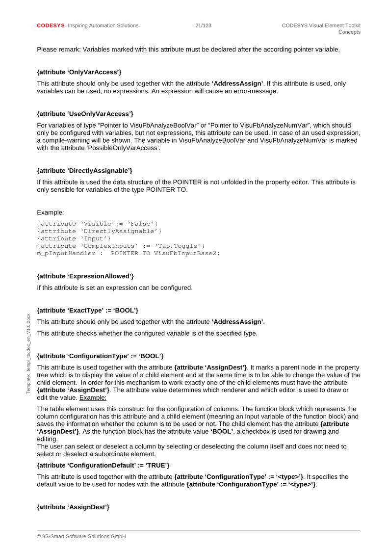
{attribute ‘DirectlyAssignable’}
If this attribute is used the data structure of the POINTER is not unfolded in the property editor. This attribute is only sensible for variables of the type POINTER TO.
Example:
{attribute ‘Visible’:= ‘False’} {attribute ‘DirectlyAssignable’} {attribute ‘Input’} {attribute ‘ComplexInputs’ := ‘Tap,Toggle’} m_pInputHandler : POINTER TO VisuFbInputBase2;
{attribute ‘ExpressionAllowed’}
If this attribute is set an expression can be configured.
{attribute ‘ExactType’ := ‘BOOL’}
This attribute should only be used together with the attribute ‘AddressAssign’.
This attribute checks whether the configured variable is of the specified type.
{attribute ‘ConfigurationType’ := ‘BOOL’}
This attribute is used together with the attribute {attribute ‘AssignDest’}. It marks a parent node in the property tree which is to display the value of a child element and at the same time is to be able to change the value of the child element. In order for this mechanism to work exactly one of the child elements must have the attribute {attribute ‘AssignDest’}. The attribute value determines which renderer and which editor is used to draw or edit the value. Example:
The table element uses this construct for the configuration of columns. The function block which represents the column configuration has this attribute and a child element (meaning an input variable of the function block) and saves the information whether the column is to be used or not. The child element has the attribute {attribute ‘AssignDest’}. As the function block has the attribute value ‘BOOL’, a checkbox is used for drawing and editing. The user can select or deselect a column by selecting or deselecting the column itself and does not need to select or deselect a subordinate element.
{attribute ‘ConfigurationDefault’ := ‘TRUE’}
This attribute is used together with the attribute {attribute ‘ConfigurationType’ := ‘<type>’}. It specifies the default value to be used for nodes with the attribute {attribute ‘ConfigurationType’ := ‘<type>’}.
{attribute ‘AssignDest’}

CODESYS Inspiring Automation Solutions 22/123 CODESYS Visual Element Toolkit Concepts
© 3S-Smart Software Solutions GmbH
Tem
plat
e: t
empl
_tec
doc_
en_V
1.0.
docx
This attribute is used together with the attribute {attribute ‘ConfigurationType’ := ‘< type >’}. It marks the input variable which is changed should the user change the variable (or the node in the property tree) with the attribute {attribute ‘ConfigurationType’ := ‘< type >’}. An example can be found above under the description of the attribute {attribute ‘ConfigurationType’ := ‘< type >’}.
{attribute ‘SubElement’}
This attribute marks variables in the configuration which are visualization elements themselves and which are therefore embedded as sub elements under the actual visualization element to be configured.
{attribute ‘UseVariableForTextOutput’}
With this attribute, the variable will be used as text output variable. In the input configuration the action ‘write a variable’ can be selected. It can be set to the text output variable or a specific variable. The element rectangle or button do have the property tree element: text output variable, which needs to be set as before. Creating a new element, the text output variable can be set to the element variable itself, by using this attribute. Note: if the attribute is used more than one time in an element, the first use will be taken as text output variable. Also: VisuFbAnalyzeTextVars and VisuFbAnalyzeNumVar do use this attribute.
{attribute ‘ReferencedImageScaleType’ := ‘<ISOTROPIC>,<ANISOTROPIC>,<FIXED>’}
This attribute is only relevant for visualization elements that draw images. It is necessary for the situation when a vector based image, e.g. SVG, is used but this image format is not supported by a targetvisualization device. In such a situation, an automatic conversion of the image format is done. To be able to determine the best size of an image for this conversion, it is recommended to put his attribute either on the function block or at the variable that determines the scaling mode.
{attribute ‘AttachedInstanceVariable’ := ‘<Name of member>’}
see 4.8 ”Link visu elements with interfaces”.
{attribute ‘AttachedInstanceType’ := ‘<Interface>’}
see 4.8 ”Link visu elements with interfaces”.
{attribute ‘RequiresValue’}
With this attribute, a compile-warning will be shown, if no value is configured for this variable in the visualization. The attribute can be used with nodes of simple data types like bool or string, as well as data types like pointer to functionblock or structures. In the second case, the following attribute is also needed.
{attribute ‘PossibleRequiredValue’}
This attribute marks the variables in a structure or functionblock, that should be checked with the attribute ‘RequiresValue’.
Example:
// warning: {attribute ‘RequiresValue’} m_ImageInfo : VisuStructImages; // no warning: m_ImageInfo2 : VisuStructImages; TYPE VisuStructImages: STRUCT // If no value is configured, a compile-warning will be shown. {attribute ‘PossibleRequiredValue’}
CODESYS Inspiring Automation Solutions 23/123 CODESYS Visual Element Toolkit Concepts
© 3S-Smart Software Solutions GmbH
Tem
plat
e: t
empl
_tec
doc_
en_V
1.0.
docx
m_stStaticID : STRING := ‘’; // no warning: m_nIsotropicType : VisuEnumIsotropicType; END_STRUCT END_TYPE
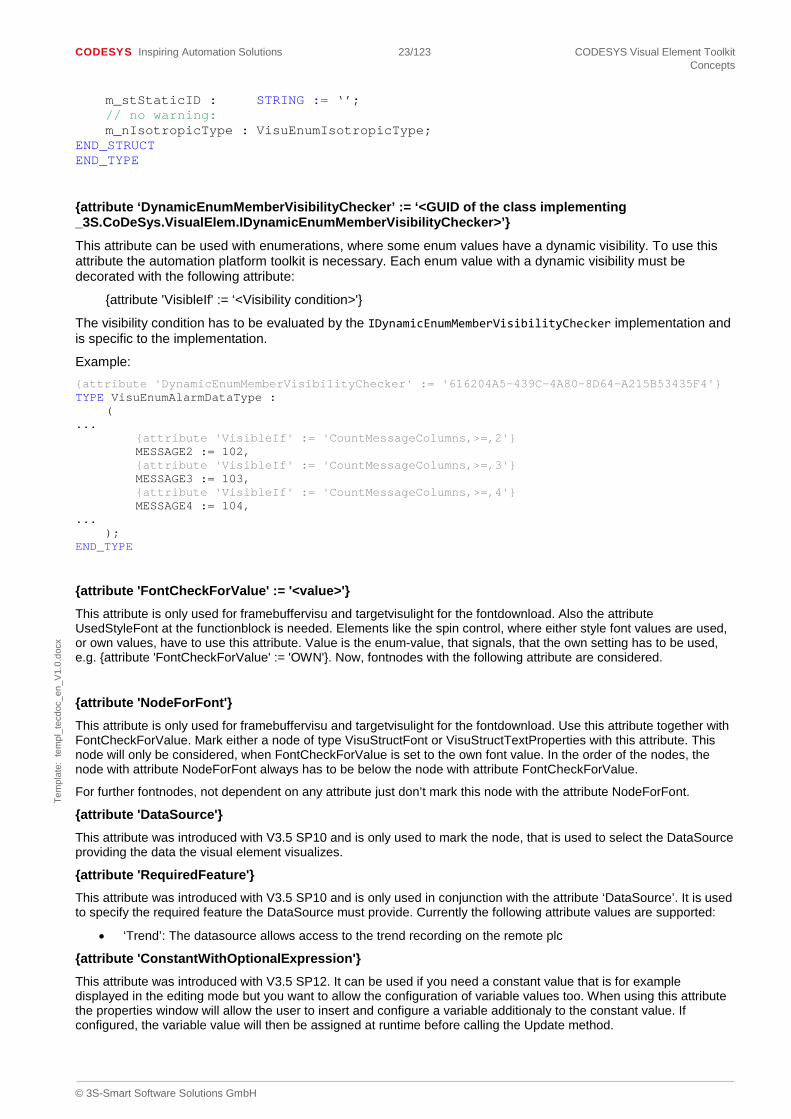
{attribute ‘DynamicEnumMemberVisibilityChecker’ := ‘<GUID of the class implementing _3S.CoDeSys.VisualElem.IDynamicEnumMemberVisibilityChecker>’}
This attribute can be used with enumerations, where some enum values have a dynamic visibility. To use this attribute the automation platform toolkit is necessary. Each enum value with a dynamic visibility must be decorated with the following attribute:
{attribute 'VisibleIf' := ‘<Visibility condition>'}
The visibility condition has to be evaluated by the IDynamicEnumMemberVisibilityChecker implementation and is specific to the implementation.
Example: {attribute 'DynamicEnumMemberVisibilityChecker' := '616204A5-439C-4A80-8D64-A215B53435F4'} TYPE VisuEnumAlarmDataType : ( ... {attribute 'VisibleIf' := 'CountMessageColumns,>=,2'} MESSAGE2 := 102, {attribute 'VisibleIf' := 'CountMessageColumns,>=,3'} MESSAGE3 := 103, {attribute 'VisibleIf' := 'CountMessageColumns,>=,4'} MESSAGE4 := 104, ... ); END_TYPE
{attribute 'FontCheckForValue' := '<value>'} This attribute is only used for framebuffervisu and targetvisulight for the fontdownload. Also the attribute UsedStyleFont at the functionblock is needed. Elements like the spin control, where either style font values are used, or own values, have to use this attribute. Value is the enum-value, that signals, that the own setting has to be used, e.g. {attribute 'FontCheckForValue' := 'OWN'}. Now, fontnodes with the following attribute are considered.
{attribute 'NodeForFont'} This attribute is only used for framebuffervisu and targetvisulight for the fontdownload. Use this attribute together with FontCheckForValue. Mark either a node of type VisuStructFont or VisuStructTextProperties with this attribute. This node will only be considered, when FontCheckForValue is set to the own font value. In the order of the nodes, the node with attribute NodeForFont always has to be below the node with attribute FontCheckForValue.
For further fontnodes, not dependent on any attribute just don’t mark this node with the attribute NodeForFont.
{attribute 'DataSource'} This attribute was introduced with V3.5 SP10 and is only used to mark the node, that is used to select the DataSource providing the data the visual element visualizes.
{attribute 'RequiredFeature'} This attribute was introduced with V3.5 SP10 and is only used in conjunction with the attribute ‘DataSource’. It is used to specify the required feature the DataSource must provide. Currently the following attribute values are supported:
• ‘Trend’: The datasource allows access to the trend recording on the remote plc
{attribute 'ConstantWithOptionalExpression'} This attribute was introduced with V3.5 SP12. It can be used if you need a constant value that is for example displayed in the editing mode but you want to allow the configuration of variable values too. When using this attribute the properties window will allow the user to insert and configure a variable additionaly to the constant value. If configured, the variable value will then be assigned at runtime before calling the Update method.
CODESYS Inspiring Automation Solutions 24/123 CODESYS Visual Element Toolkit Concepts
© 3S-Smart Software Solutions GmbH
Tem
plat
e: t
empl
_tec
doc_
en_V
1.0.
docx
An example for the usage of this attribute is the scale of a meter element. There the meter can use the constant value for displaying within the visualization editor but it can allow the users to change the borders of the scale using variables too.
2.1.3 General attributes for functions
{attribute 'conditionalshow' := ‘<value>’}
This attribute can be used to show a function or method or functionblock, depending on an argument. An explanation of the commandline argument is found here.
2.1.4 Attributes related to visualization styles
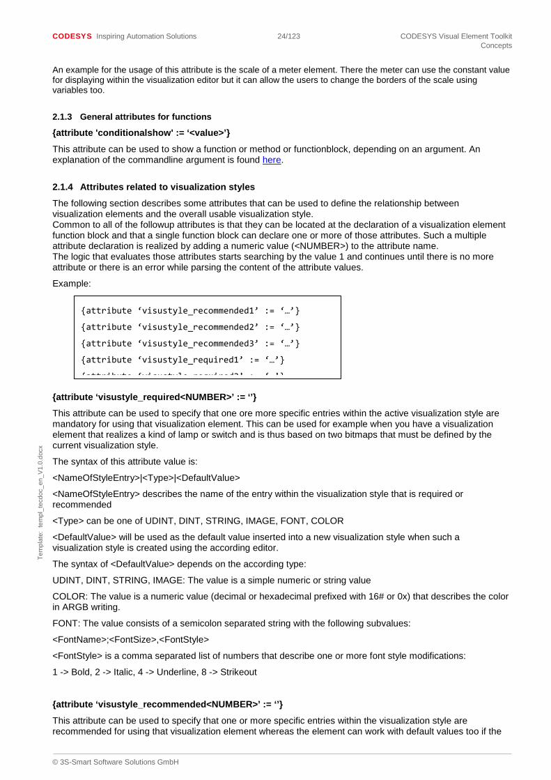
The following section describes some attributes that can be used to define the relationship between visualization elements and the overall usable visualization style. Common to all of the followup attributes is that they can be located at the declaration of a visualization element function block and that a single function block can declare one or more of those attributes. Such a multiple attribute declaration is realized by adding a numeric value (<NUMBER>) to the attribute name. The logic that evaluates those attributes starts searching by the value 1 and continues until there is no more attribute or there is an error while parsing the content of the attribute values.
Example:
{attribute ‘visustyle_required<NUMBER>’ := ‘’}
This attribute can be used to specify that one ore more specific entries within the active visualization style are mandatory for using that visualization element. This can be used for example when you have a visualization element that realizes a kind of lamp or switch and is thus based on two bitmaps that must be defined by the current visualization style.
The syntax of this attribute value is:
<NameOfStyleEntry>|<Type>|<DefaultValue>
<NameOfStyleEntry> describes the name of the entry within the visualization style that is required or recommended
<Type> can be one of UDINT, DINT, STRING, IMAGE, FONT, COLOR
<DefaultValue> will be used as the default value inserted into a new visualization style when such a visualization style is created using the according editor.
The syntax of <DefaultValue> depends on the according type:
UDINT, DINT, STRING, IMAGE: The value is a simple numeric or string value
COLOR: The value is a numeric value (decimal or hexadecimal prefixed with 16# or 0x) that describes the color in ARGB writing.
FONT: The value consists of a semicolon separated string with the following subvalues:
<FontName>;<FontSize>,<FontStyle>
<FontStyle> is a comma separated list of numbers that describe one or more font style modifications:
1 -> Bold, 2 -> Italic, 4 -> Underline, 8 -> Strikeout
{attribute ‘visustyle_recommended<NUMBER>’ := ‘’}
This attribute can be used to specify that one or more specific entries within the visualization style are recommended for using that visualization element whereas the element can work with default values too if the
{attribute ‘visustyle_recommended1’ := ‘…’}
{attribute ‘visustyle_recommended2’ := ‘…’}
{attribute ‘visustyle_recommended3’ := ‘…’}
{attribute ‘visustyle_required1’ := ‘…’}
{attribute ‘visustyle required2’ := ‘ ’}

CODESYS Inspiring Automation Solutions 25/123 CODESYS Visual Element Toolkit Concepts
© 3S-Smart Software Solutions GmbH
Tem
plat
e: t
empl
_tec
doc_
en_V
1.0.
docx
according style is not defined. The syntax of the value is the same than in ‘visustyle_required’.
{attribute ‘initfromstyle<NUMBER>’ := ‘’}
Using this attribute, a visualization element can be initialized using values from the visualization style that is active when the element is inserted into the visualization. This can be used for example on an element like the “windows button” to specify the default color. Thus it is possible to insert a button that is initialized with the “Control color” from the visualization style and will change it’s color according to the currently active style.
The syntax is:
<InstancePathOfMember>|<Type>|<NameOfStyleEntry>|<DefaultValue>
<InstancePathOfMember> is the instance path of the member that should be assigned with the value from the visualization style as seen from the scope within the visualization element function block. This could be something like “m_StaticColors.NormalColors.dwFrameColor”.
<Type>, <NameOfStyleEntry> and <DefaultValue> have the same syntax and meaning than in ‘visustyle_required’.
In initfromstyle the following types are supported: FONT, COLOR, FONTCOLOR
Additional <Type>: FontColor. Here the values for the font and the fontcolor are set.
NameOfStyleEntry: set the style-entry for the font and also for the font color.
DefaultValue: First the font default value, then the color default value
Example:
{attribute ‘initfromstyle1’ :=
‘m_Labels.Font|FontColor|Font-Standard;Font-Color|Arial;12;16#FF000000’}
The <DefaultValue> will be used when the active visualization style does not define an entry with the the according name.
2.2 Procedure
The general procedure of a visualization includes the cyclical call of the following methods of the interface IvisualElement:
The HandleInput call is optional and is only required for keyboard or mouse input. The internal state of the visualization element is set in the Update method, this also includes the values needed by the paint call.
In GetUpdateRects the visualization element loads the display areas to be updated into the processing list. And finally the actual drawing process of the visualization element takes place in Paint.
Please remark: Since CODESYS 3.5 SP5 Patch 2 (CDS-38149), an additional call to the Method “Update” could be done in some cycles before the call to “HandleInput”.
2.3 Code conversion for the integrated Visualization/Web Visualization
The IEC code created when developing visualization elements in IEC is automatically transformed into C# when creating a visualization profile.. The reason for this is that the converted code is used for the integrated visualization as well as for the editing mode of the visualization editor. As the languages in IEC and C# are not always identically powerful the element developer has to observe some restrictions for the visualization elements to be converted automatically.

CODESYS Inspiring Automation Solutions 26/123 CODESYS Visual Element Toolkit Concepts
© 3S-Smart Software Solutions GmbH
Tem
plat
e: t
empl
_tec
doc_
en_V
1.0.
docx
2.3.1 Restrictions when developing Elements
The following constructs can be used with restrictions. If the constructs are not marked with a pragma or an attribute, an error message is displayed and the assembly or the JAR file are not created.
• SIZEOF Operator
o Only admissible for determining the size of basic data types
o Must be marked with the pragma ieccodeconversion_replacesizeofbybytesize_on/ ieccodeconversion_replacesizeofbybytesize_off.
• TIME Operator
o Only for measuring time differences
o Must be marked with the pragma ieccodeconversion_enabletimeoperator/ ieccodeconversion_disabletimeoperator.
• Constant NULL
o Must be marked with the attribute ieccodeconversion_null_constant. • POINTER TO BYTE
o Only admissible when used as char array.
o Must be marked with the attribute ieccodeconversion_character_array.
• POINTER TO <basic data type>
o Only admissible when transferring a reference to a function or method. May not be used as a local variable in a program, function block, method or function.
o Use together with ADR operator.
• Data types without prefix
o Are represented by the next biggest data type in C#.
o Some operations such as ‘ROR’, ‘ROL’and ‘+’ for example may cause an overflow and must be marked as uncritical with the pragma ieccodeconversion_omit_unsigned_warning_on / ieccodeconversion_omit_unsigned_warning_off where used.
The following constructs are not supported:
• Data type BitConst
o Not supported because not explicit (not only BOOL but also INTEGER data type)
• Assignments within conditions
o For example an assignment within the condition of an IF statement. Such code parts have to be rewritten.
• Pragmas
o Only a selection of predefined pragmas (used in the library VisuElemBase) is supported.
2.3.2 Attributes for Code Conversion
A series of additional attributes which control the conversion are available when converting the IEC code of the visualization elements or the visualization libraries to C# (integrated visualization).
{attribute ‘ieccodeconversion_additional_objecttype’}
This attribute is used for structures which have a generic component of the type “POINTER TO DWORD” for example, which passes on numerical values, pointer to structures, function blocks or strings. An additional component type “object” or “Object” is generated with this attribute.

CODESYS Inspiring Automation Solutions 27/123 CODESYS Visual Element Toolkit Concepts
© 3S-Smart Software Solutions GmbH
Tem
plat
e: t
empl
_tec
doc_
en_V
1.0.
docx
{attribute ‘visucodeconversion_additional_pou’ := ‘<List of POUs>’}
This attribute can be used with visualization elements for creating a list separated by “;” of additional POUs which are needed for a correct conversion.
Example: {attribute ‘visucodeconversion_additional_pou’ := ‘VisuElemBase.VisuFbAnalyzeTextVarsConverted;VisuElems.Visu_EditboxInputBordersConverted;VisuElems.Visu_EditboxInputConverted’}
{attribute ‘visucodeconversion_predefinedidentifiers’ := ‘<List of C# identifiers>’}
This attribute can be used with visualization elements if the visualization element calls functions or methods, that contain embedded C# code snippets (embedded as comment // @IECCodeConverter_C#:). The attribute value is a list (separated by ;) of the C# identifiers.
Example: {attribute 'visucodeconversion_predefinedidentifiers' := ' PositiveInfinity;NegativeInfinity'}
{attribute ‘ieccodeconversion_array’}
This attribute is given to a variable type “POINTER TO <something>” if it is accessed per index. This attribute makes sure the code is converted correctly.
{attribute ‘ieccodeconversion_character_array’}
Variables type “POINTER TO BYTE” or “POINTER TO WORD” must be given this attribute if the addresses of string variables are stored there. Such variables have the type “char[]” in the converted code.
{attribute ‘visucodeconversion_clientdata_variable’}
Together with the attribute “visucodeconversion_position_variable” this attribute is used for visualization elements to mark the variables in which the POINTER TO VisuStructClientData is saved. This is required to visualize the error state of the visualization element (for additionally generated code in the method paint).
{attribute ‘visucodeconversion_clientspecificdata’}
This attribute must always be used together with the attribute “visucodeconversion_clientspecificdata”. It marks the variable type POINTER TO <something> which points to the client-specific data area.
{attribute ‘visucodeconversion_clientspecificdataindex’}
This attribute must always be used together with the attribute “visucodeconversion_clientspecificdata”. It marks the corresponding index variable.
{attribute ‘visucodeconversion_complexelement_initprovider’}
Contains the GUID of the class which implements the interface IcomplexElementCall and provides the extended (initialization) functionality for a visualization element.
{attribute ‘ieccodeconversion_createarrayfactorymethod’}
This attribute must accompany all types which are used in a dynamic array in the configuration of a visualization element, for example for the type VisuStructPoint which is used in the visualization element “polygon”. An array of this type (as “object[]“ or “Object“) can be created with this attribute using a generic factory method.
Please note:
- It is not an absolute must for this type to implement a pre-defined interface (see attribute “ieccodeconversion_implementexistinginterface“).
- The attribute “ieccodeconversion_creategenericsetter“ should accompany this attribute, to make sure the (empty) instances created with the factory method can be filled.

CODESYS Inspiring Automation Solutions 28/123 CODESYS Visual Element Toolkit Concepts
© 3S-Smart Software Solutions GmbH
Tem
plat
e: t
empl
_tec
doc_
en_V
1.0.
docx
- The optional attribute value can be used to specify the name of the array’s base class. This is necessary if the attribute is used by a derived function block whereas the array will be instantiated by the base function block name (available since V3.4 SP3)
{attribute ‘ieccodeconversion_createfactorymethod’}
If a type has this attribute, a factory method for the creation of an instance is generated. For this purpose the type must implement a pre-defined interface (see attribute “ieccodeconversion_implementexistinginterface“).
{attribute ‘visucodeconversion_creategenericdynamicarrayelementgetter’}
This attribute can be used for visualization elements which use dynamic arrays in their configuration (attribute “DynamicArray”). It generates a generic getter for dynamic arrays which gives access to a certain array element.
{attribute ‘ieccodeconversion_creategenericsetter’}
In structures with this attribute, the structure components can be set with a generic setter method. The structure components are identified via their name. This attribute is usually used together with the attribute “ieccodeconversion_createarrayfactorymethod”.
Please note:
- The optional attribute value can be used to specify the name of the class. This is necessary if the attribute is used by a derived function block (available since V3.4 SP3)
{attribute ‘ieccodeconversion_creategenericsetterexplicitely’}
This attribute is similar to “ieccodeconversion_creategenericsetter” but only observes the structure components in the getter which have the attribute “ieccodeconversion_useforgettersetter”.
{attribute ‘ieccodeconversion_creategenericgetter’}
In structures with this attribute, the structure components can be determined with a generic getter method. The structure components are identified via their name.
{attribute ‘ieccodeconversion_creategenericgetterexplicitely’}
This attribute is similar to “ieccodeconversion_creategenericgetter” but only observes the structure components in the getter which have the attribute “ieccodeconversion_useforgettersetter”.
{attribute ‘ieccodeconversion_datatype’ := ‘byte[]’}
With this attribute you can change the type of a variable or a parameter to another type. Is often required for variables whose type cannot generally be converted to C#, e.g. POINTER TO <scalar data type>.
Examples:
- {attribute ‘ieccodeconversion_datatype’ := ‘short []’}: Sets the type for both target languages to “short[]”
- {attribute ‘ieccodeconversion_datatype’ := ‘Java:_3s.CODESYS.visugenerated.Ivisu_InputChecks;C#:_3S.CODESYS.VisuGenerated.Ivisu_InputChecks’}: Sets the type for the two target languages to different types which are fully qualified. In fact the Java-part is ignored at the moment; nevertheless it must not be omitted.
- {attribute ‘ieccodeconversion_datatype’ := ‘Java:Object;C#:object’}: Sets the type for the two target languages to the same type which is called differently in the target languages. In fact the Java-part is ignored at the moment; nevertheless it must not be omitted.
{attribute ‘ieccodeconversion_deeply_clonable’}
This attribute can be used for structures or function blocks.

CODESYS Inspiring Automation Solutions 29/123 CODESYS Visual Element Toolkit Concepts
© 3S-Smart Software Solutions GmbH
Tem
plat
e: t
empl
_tec
doc_
en_V
1.0.
docx
With this attribute the class implements the interface IdeeplyCloneable in the target language and provides a method Clone(IglobalContext) with which a complete copy of the instance can be created.
{attribute ‘ieccodeconversion_define_identifiers’ := ‘<list of identifiers>’}
This attribute must be used for functions or methods which receive code for the target language per inline code. The identifiers in the list of identifiers are separated by semicolons. This attribute makes sure the identifier is always spelled consistently. This construct is only required for the called functions or methods themselves but not for the parameters of called functions.
Example:
{attribute ‘ieccodeconversion_define_identifiers’ := ‘MyFunction’} FUNCTION TestFunction : BOOL VAR_INPUT myParameter : ... END_VAR ...
//@IECCodeConverter: __retVal = MyFunction(myParameter, globalContext);
{attribute ‘ieccodeconversion_disabletimeoperator’}
Prohibits the usage of the TIME operator for the initialization of a TIME variable upon its declaration.
{attribute ‘ieccodeconversion_enabletimeoperator’}
Permits the usage of the TIME operator for the initialization of a TIME variable upon its declaration.
{attribute ‘ieccodeconversion_externalimplementation’ := ‘<Guid>’}
Marks a complete function block, individual methods or functions which were implemented externally (in C#). Required for constructs which cannot be converted into the target language.
Example : {attribute ‘ieccodeconversion_externalimplementation’ := ‘214162F2-E5F1-4673-92B4-5A5CE6491A5D’}
{attribute ‘ieccodeconversion_fbinitparameter’ := ‘<order criterion>’}
Must be used together with the attribute ieccodeconversion_createfactorymethod, if the function block’s FB_Init method has more than the 2 default parameters. The function block components, that will be initialized by FB_Init must be marked with this attribute, where the attribute value is an arbitrary order criterion, that ensures, that the parameters are passed in the correct order.
{attribute ‘ieccodeconversion_generate_checksum’}
Marks a function block in order to generate a checksum method which 29verridd the current values of all variables.
{attribute ‘ieccodeconversion_generate_usegeneratedchecksum’}
The function block which contains the method this attribute is used for must have the attribute „ieccodeconversion_generate_checksum“. With this attribute the method calls the generated checksum method.
{attribute ‘ieccodeconversion_generategetter’ := ‘<getter name>}
This attribute is used in GVLs in visualization libraries and generates a getter which can access the value of a global constant or variable.
Example: {attribute ‘ieccodeconversion_generategetter’ := ‘GetVisuDbfFixedValue’}

CODESYS Inspiring Automation Solutions 30/123 CODESYS Visual Element Toolkit Concepts
© 3S-Smart Software Solutions GmbH
Tem
plat
e: t
empl
_tec
doc_
en_V
1.0.
docx
{attribute ‘ieccodeconversion_generategetter’ := ‘<optional type>’}
Can be used for components of a structure. Generates a getter which can access components.
The attribute value can be omitted. The attribute value may contain the type used. If the attribute value is omitted, the type is automatically defined.
{attribute ‘ieccodeconversion_generategettersetter’ := ‘<optional type>’}
Can be used for components of a structure. Generates a getter and a setter which can access components.
The attribute value can be omitted. The attribute value may contain the type used. If the attribute value is omitted, the type is automatically defined.
{attribute ‘ieccodeconversion_generatesetter’ := ‘<optional type>’}
Can be used for components of a structure. Generates a setter which can access components.
The attribute value can be omitted. The attribute value may contain the type used. If the attribute value is omitted, the type is automatically defined.
{attribute ‘ieccodeconversion_generate_variableowner_callback’}
The attribute is relevant for function blocks in IEC which pass on local variables to another function block for modification using a pointer. This is not possible in the converted code and a call back mechanism is generated instead, i.e.
- The class representing the function block implements the interface IvariableOwner.
- The corresponding GetValueAs* and WriteValueAs* methods are generated.
The attribute ‘ieccodeconversion_variableowner_variable’ is relevant in the context of this attribute. If there is no variable with the attribute ‘ieccodeconversion_variableowner_variable’ in the function block a warning is issued upon code conversion.
{attribute ‘ieccodeconversion_gettersetter_norecursion’}
When a generic getter or setter is generated this attribute makes sure only the structure component itself and not its potentially embedded child elements are accessed.
{attribute ‘visucodeconversion_genericsetter_initializedflag’ := ‘<variable name>’}
This attribute is used for function blocks which 30verrid an IEC variable. It contains the variable which marks the function block as “initialized”. This is usually done after the variable to be monitored has been registered. In the generic setter this flag is then reset.
Example: {attribute ‘visucodeconversion_genericsetter_initializedflag’ := ‘_bInitialized’}
{attribute ‘visucodeconversion_genericsetter_stringtarget’ := ‘<variable name>’}
This attribute is used for function blocks which 30verrid an IEC variable. It is used to mark the string variable which may contain the name of the variable in the function block provided for the converted code.
Example: {attribute ‘visucodeconversion_genericsetter_stringtarget’ := ‘pstTextVariable’}
{attribute ‘visucodeconversion_genericsetter_visualelement’ := ‘<variable name>’}
This attribute is used for function blocks which 30verrid an IEC variable. It is used to mark the variable which may contain the visualization element instance in the function block provided for the converted code.
Example: {attribute ‘visucodeconversion_genericsetter_visualelement’ := ‘_owningElement’}

CODESYS Inspiring Automation Solutions 31/123 CODESYS Visual Element Toolkit Concepts
© 3S-Smart Software Solutions GmbH
Tem
plat
e: t
empl
_tec
doc_
en_V
1.0.
docx
{attribute ‘ieccodeconversion_ignoreinfactorymethod’}
May be used together with the attribute ieccodeconversion_createfactorymethod Such structure components are then ignored in the generated factory method.
{attribute ‘ieccodeconversion_ignoreingettersetter’}
May be used together with the attribute ieccodeconversion_creategenericsetter. Such structure components are then ignored in the generated setter.

CODESYS Inspiring Automation Solutions 32/123 CODESYS Visual Element Toolkit Concepts
© 3S-Smart Software Solutions GmbH
Tem
plat
e: t
empl
_tec
doc_
en_V
1.0.
docx
{attribute ‘ieccodeconversion_implementexistinginterface’}
A type with this attribute implements a specified interface and can be used by the programmed part of the visualization. If the type is to implement more than one specified interface, the interfaces are separated by semicolons in the attribute value.
Example: {attribute ‘ieccodeconversion_implementexistinginterface’ := ‘_3S.CODESYS.VisuGenerated.Ivisu_EditboxInput’}
Example: {attribute ‘ieccodeconversion_implementexistinginterface’ := ‘ _3S.CODESYS.ConvertedIECCode.IgenericSetterProvider;_3S.CODESYS.ConvertedIECCode.IgenericGetterProvider’}
{attribute ‘visucodeconversion_interfaceassembly’ := ‘<assembly name>’}
This attribute can be used for visualization elements which use the IcomplexElementCall interface and declare compound interfaces to guarantee for the element functionality. The attribute value is the name of the assembly which contains these interfaces.
Example: {attribute ‘visucodeconversion_interfaceassembly’ := ‘VisuInterfaceExtensions.dll’}
{attribute ‘ieccodeconversion_null_constant’}
Marks a global constant type “POINTER TO BYTE” for it to describe the null.
{attribute ‘ieccodeconversion_omit_conversion’}
Marks a variable or a parameter for it to be omitted from conversion.
{attribute ‘ieccodeconversion_only_reference’}
Marks a structure or a function block, that instances of the structure or function block are never passed by value but always passed by reference. Therefore the generated methods __GetDeepCopy and __MOVE will be omitted.
{attribute ‘visucodeconversion_position_variable’}
This attribute is used together with the attribute ‘visucodeconversion_clientdata_variable’ for visualization elements in order to mark the VisuStructPaintRectangle variable which contains the current position of the element. This is required to visualize the error state of the visualization element (for additionally generated code in the method paint).
{attribute ‘visucodeconversion_publicobjectfactoryinterface’ := <interface name>}
This attribute can be used for visualization elements which use the IcomplexElementCall interface and create types from the converted code in the external implementation. The attribute value is the name of the interface which additionally implements the IvisuGeneratedAssemblyObjectFactory and contains this method.
Example: {attribute ‘visucodeconversion_publicobjectfactoryinterface’ := ‘ IgeneratedTraceAssemblyObjectFactory’}
{attribute ‘ieccodeconversion_reflection_method’}
Obsolete. Marks a method which returns interfaces.
{attribute ‘ieccodeconversion_replacesizeofbybytesize_off’}
Prohibits the usage of SIZEOF for the initialization of scalar variables upon their declaration.

CODESYS Inspiring Automation Solutions 33/123 CODESYS Visual Element Toolkit Concepts
© 3S-Smart Software Solutions GmbH
Tem
plat
e: t
empl
_tec
doc_
en_V
1.0.
docx
{attribute ‘ieccodeconversion_replacesizeofbybytesize_on’}
Permits the usage of SIZEOF for the initialization of scalar variables upon their declaration.
{attribute ‘ieccodeconversion_requiredexternalmethod’}
Only required in visualization libraries. Marks functions which are required for the correct execution of the visualization and must be available as callback functions in the programmed part of the visualization.
{attribute ‘ieccodeconversion_return_object’}
May be used for methods and functions whose return value is a POINTER TO <scalar data type>. Methods and functions marked like this return “object” or “Object” in the converted code.
{attribute ‘visucodeconversion_typenodecrcid’}
To be used internally only. Issues the CRC-ID for structure components which is to be used for SetValueGeneric.
{attribute ‘ieccodeconversion_useexistinginterface’ := ‘<interface name>’}
Is used for interfaces in the visualization libraries. The interface is not converted and an existing interface is used.
Example: {attribute ‘ieccodeconversion_useexistinginterface’ := ‘_3S.CODESYS.VisuGenerated.IVisualisationIEC’}
{attribute ‘ieccodeconversion_usetypeforfactory ‘ := ‘<type name>’}
This attribute is only relevant for function blocks with the attribute “ComplexInput”. It determines that the factory method does not instantiate the function block itself for the function block instantiation. Instead the sub class to be used for the converted code is instantiated.
Example: {attribute ‘ ieccodeconversion_usetypeforfactory’ := ‘ Visu_ToggleInputConverted’}
{attribute ‘ieccodeconversion_variableowner_variable’}
This attribute is used together with the attribute ‘ieccodeconversion_generate_variableowner_callback’. It marks the variables which are passed on to another function block by a pointer for modification in IEC and have to be observed in the generated GetValueAs* and WriteValueAs* methods.
2.3.3 Pragmas for Code Conversion
Apart from the attributes there is a series of pragmas which also control the conversion.
{ieccodeconversion_enabletimeoperator}
This pragma permits the usage of the TIME operator, meaning that warnings issued when the TIME operator is used are suppressed. By using this pragma the element developer signalizes that he is familiar with the restrictions arising when working with the TIME operator and will make correct use of it. Every usage of this pragma must be concluded with the pragma {ieccodeconversion_disabletimeoperator}.
{ieccodeconversion_disabletimeoperator}
This pragma deactivates the TIME operator.
{ieccodeconversion_omit_conversion_on}
The code following the pragma is not converted. This behaviour is terminated by the pragma {ieccodeconversion_omit_conversion_off}.

CODESYS Inspiring Automation Solutions 34/123 CODESYS Visual Element Toolkit Concepts
© 3S-Smart Software Solutions GmbH
Tem
plat
e: t
empl
_tec
doc_
en_V
1.0.
docx
{ieccodeconversion_omit_conversion_off}
The code following this pragma is converted.
{ieccodeconversion_omit_unsigned_warning_on}
This pragma permits the usage of unsigned data types, meaning that warnings issued upon the usage of unsigned data types which could cause an overflow are suppressed. By using this pragma the element developer signalizes that he has checked the relevant operations and made sure that an overflow is not possible. Every usage of this pragma must be concluded with the pragma {ieccodeconversion_omit_unsigned_warning_off}.
Example:
Adding two BYTE variables and saving the result in another BYTE variable may cause an overflow in IEC which creates a result which is smaller that the mathematical sum. In the converted code, the next bigger signed data types (i.e. 2-byte data type short) are used avoiding an overflow because the result of the addition is always the sum of the two summands.
{ieccodeconversion_omit_unsigned_warning_off}
This pragma reactivates the warnings when working with operations with unsigned data types.
{ieccodeconversion_replacesizeofbybytesize_on}
When using with this pragma the byte size of the respective variable is used when working with the SIZEOF operator. Every usage of this pragma must be concluded with the pragma {ieccodeconversion_replacesizeofbybytesize_off}.
Example:
If iVar is an INT variable, the value 2 is used for SIZEOF(iVar).
{ieccodeconversion_replacesizeofbybytesize_off}
When using this pragma an error message is issued when working with the SIZEOF operator.
What is more, pragmas can also be used within comments for code conversion. These are needed when specifying the C# code to be used with inline code (in a comment), for example when wanting to circumvent non-convertible IEC constructs.
The following pragmas are supported:
‘preventnormalize’ := ‘<identifier>’
The identifier specified in the pragma is not normalized/obfuscated. This is required, for example, for predefined identifiers of the target language, e.g. in Java for the method containsKey of the class hash table. Such a pragma may be used several times in succession. The pragma
‘endpreventnormalize’
deletes all previously specified exclusions.

CODESYS Inspiring Automation Solutions 35/123 CODESYS Visual Element Toolkit Concepts
© 3S-Smart Software Solutions GmbH
Tem
plat
e: t
empl
_tec
doc_
en_V
1.0.
docx
2.4 Localization
As visualization elements can be used in CODESYS versions all over the world, there must be a way for developers of such elements to provide localized texts for the generic visualization editor for at least those languages that are supported by the programming system itself.
This chapter contains some general information about how the localization of visual elements is done by the editor. The attributes related to localization are described in the attributes section above.
All localized texts for visual elements are provided using the TextList object that is available in the CODESYS programming system. To be able to give such textlists to external translators, the according textlist editor supports several mechanisms for exporting and importing textlists to and from files. Such a textlist that is used for localizing visual elements must match some preconditions:
- The search for texts is always done using the id of a text. The comparison of text ids is done in a case sensitive way.
- The languages in such a textlist must use the following predefined names (as used by the programming system) without quotes:
o “en”: English language
o “de”: German language
o “es”: Spanish language
o “fr”: French language
o “it”: Italian language
o “zh-CHS”: Chinese language
- If a text or the whole column for the current language (configured in the programming system) is not found, then the Default-Text will be used.
- To provide a consistent user interface for missing localizations, the “Default” column should contain the same text than the English column (“en”)
- To prevent those textlists being downloaded to the plc for the targetvisualization/webvisualization, there is a setting in the object properties of the textlists:
Uncheck this box to prevent the automatic download by the visualization, ie. Give CODESYS a chance for deciding which textlist is used for the visualization and which one is only used for localization of the visual editor.
Common to all localization attributes is the format of their attribute value. This value references the text id (and optionally the according textlist). The content of this attribute value can thus use one of the following two formats:
- <TextListName>.<TextID>: This is the recommended way for providing a text reference as it makes the search for the text slightly faster (probably not noticeable for the user at all). Example: {attribute ‘DisplayTextId’ := ‘ElementLocalizations.PositionText’}

CODESYS Inspiring Automation Solutions 36/123 CODESYS Visual Element Toolkit Concepts
© 3S-Smart Software Solutions GmbH
Tem
plat
e: t
empl
_tec
doc_
en_V
1.0.
docx
- <TextID>: Providing text references this way allows a better readability of the declarations of the visual element. The search for the according text is done by looking into all toplevel textlists within the current library. The first textlist that contains this text is used. In case of ambiguities, there is no defined search order! Example: {attribute ‘DisplayTextId’ := ‘PositionText’}
To simplify the localization, the command “Check visual elements” will issue some warnings pointing to those locations where a localization is missing.
2.4.1 Localization of an already existing visual extension
Since V3.5 SP6 there exists an additional possibility to provide the localization for an already existing visual extension without generating the visual extension again.
The Visual Element Repository dialog contains two buttons, which export resp. import the localization of the currently selected visual extension.
2.4.1.1 Export
There are two use cases for the export process:
• Initial export to export all the localization to import (= initial import) it in an external translation tool
• Periodical export: Needed to update the texts in the external translation tool in order to determine new or changed texts.
The settings of this dialog:
• Export path: The path, where the export files will be written to • Only default language (*.resx): Creates only the resx-files for the periodical export • All languages (*.resx and *.tmx): Creates all the files for the initial import • Default language in translation software: The language code of the default language in the external
translation tool
The export functionality can be also launched by the following command line arguments:
--exportVisuExtensionLocalization <Name of visualization repository> <Name of visual extension> <Export path> <Flag: Create all the files for the initial import?> <default language of external translation tool>
2.4.1.2 Import
The import functionality imports all the *.tmx files of a given directory into the currently selected visual extension.
The import functionality can be also launched by the following command line arguments:
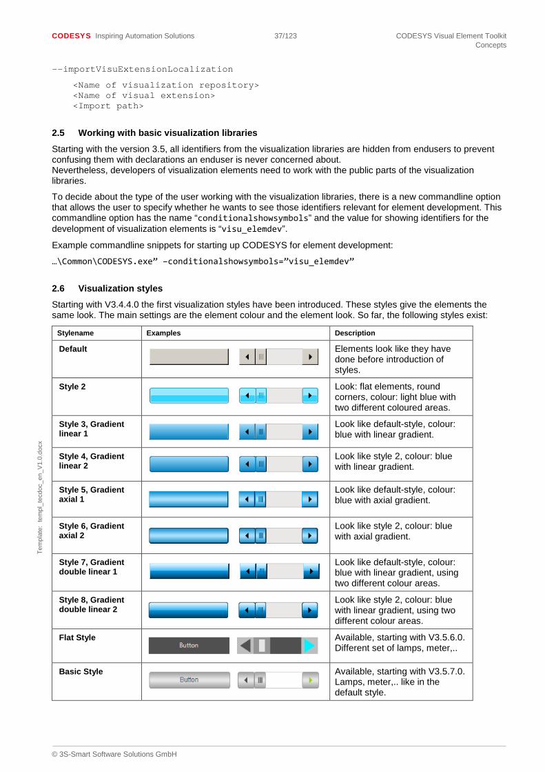
CODESYS Inspiring Automation Solutions 37/123 CODESYS Visual Element Toolkit Concepts
© 3S-Smart Software Solutions GmbH
Tem
plat
e: t
empl
_tec
doc_
en_V
1.0.
docx
--importVisuExtensionLocalization
<Name of visualization repository> <Name of visual extension> <Import path>
2.5 Working with basic visualization libraries
Starting with the version 3.5, all identifiers from the visualization libraries are hidden from endusers to prevent confusing them with declarations an enduser is never concerned about. Nevertheless, developers of visualization elements need to work with the public parts of the visualization libraries.
To decide about the type of the user working with the visualization libraries, there is a new commandline option that allows the user to specify whether he wants to see those identifiers relevant for element development. This commandline option has the name “conditionalshowsymbols” and the value for showing identifiers for the development of visualization elements is “visu_elemdev”.
Example commandline snippets for starting up CODESYS for element development:
…\Common\CODESYS.exe” –conditionalshowsymbols=”visu_elemdev”
2.6 Visualization styles
Starting with V3.4.4.0 the first visualization styles have been introduced. These styles give the elements the same look. The main settings are the element colour and the element look. So far, the following styles exist:
Stylename Examples Description
Default
Elements look like they have done before introduction of styles.
Style 2
Look: flat elements, round corners, colour: light blue with two different coloured areas.
Style 3, Gradient linear 1
Look like default-style, colour: blue with linear gradient.
Style 4, Gradient linear 2
Look like style 2, colour: blue with linear gradient.
Style 5, Gradient axial 1
Look like default-style, colour: blue with axial gradient.
Style 6, Gradient axial 2
Look like style 2, colour: blue with axial gradient.
Style 7, Gradient double linear 1
Look like default-style, colour: blue with linear gradient, using two different colour areas.
Style 8, Gradient double linear 2
Look like style 2, colour: blue with linear gradient, using two different colour areas.
Flat Style
Available, starting with V3.5.6.0. Different set of lamps, meter,..
Basic Style
Available, starting with V3.5.7.0. Lamps, meter,.. like in the default style.

CODESYS Inspiring Automation Solutions 38/123 CODESYS Visual Element Toolkit Concepts
© 3S-Smart Software Solutions GmbH
Tem
plat
e: t
empl
_tec
doc_
en_V
1.0.
docx
White Style
Available, starting with V3.5.7.0. Different set of lamps, meter,..
For more information also have a look at the online help (Visualization – Visualization styles). There is also a description of the styles-editor!
2.7 Handling of Multitouch inputs
Starting with version 3.5 SP5 it is possible that visualization elements react to multitouch inputs.
The typical way of handling these inputs is by simply reacting to the usual mouse events. The core of the visualization translates the touch events into according mouse events. For element developers this has the effect that maybe used assumptions like “no two subsequent MouseDown events without inbetween MouseUp” no longer hold on such systems. It is for example possible that two fingers touch the same element without releasing in between.
As some of the formerly existing objects handling the mouse-events are not flexible enough to handle touch events too, these have been superseded by more general implementations. For compatibility reasons, the old variants are still there. Nevertheless, from now on these are hidden to prevent accidentally using them.
This affects the following variables:
- Visu_InputData.CapturingElement: replaced by Visu_InputData.Capturing and the according methods
- Visu_InputData.LastElement: replaced by Visu_InputData.LastElementInfo and the according methods
Using these recent implementations it should be possible to realize the same functionality than before like implementing dragging of arbitrary elements by using the methods of Visu_InputData.Capturing. The according implementation handles the fact that there may be more than one active touch at a time. In fact, the event variable dwParam2 of mouseevents hold additional information that allows the visualization to distinguish different touches or real mouse events.
If elements implement handling of mouse down (like tapping or dragging) but are not using the standard configuration way (MouseDown-Event, Tap-Variable), then such elements have to tell the visualization core that they are reacting to these events. This is necessary for the according device to be able to decide which gesture to raise when there are ambiguous possibilities (e.g. the element is located in a scrollable frame). This notification can be done by implementing the interface IrectangleProvider in the according element. The method AddRectangles will then be called at appropriate times and the elements gets a chance for providing the areas where it wants to react to MouseDown event.
2.8 Visualization elements and Onlinechange
Starting with the version CODESYS 3.5 SP6, the handling of onlinechanges has been simplified for visualization elements. The new mechanism is active for compilerversion >= 3.5.6, visualization profile >= 3.5.6 and runtime systems >= 3.5.5. Older combinations will still use the old mechanism.
Using the new mechanism, all visualization elements will be initialized completely new when an onlinechange affecting data (visu or plc) is executed. That means that FB_EXIT(FALSE), FB_INIT(FALSE, FALSE) will be called on all according element instances (if implemented). To make sure that there is no inconsistent data after an onlinechange, signatures declaring global data (VAR_GLOBAL, PROGRAM, VAR_STAT) should be marked with the following attribute:
{attribute ‘explicit-init-exit-handling‘ := ‘visu’}
That makes sure that according variables are (re)initialized in the same way and thus consistently to visualization elements. Of course the functionality should be tested after these changes when using device/programmingsystem combinations as described above.
Independently of this new reinitialization, any kind of ressources, that are not managed by the visualization itself and that are allocated by a visualization element or a comparable function block still have to be released correctly. This is typically done in calls to FB_EXIT(FALSE). Examples for such resources are for example System memory, semaphores,…

CODESYS Inspiring Automation Solutions 39/123 CODESYS Visual Element Toolkit Visualization Library
© 3S-Smart Software Solutions GmbH
Tem
plat
e: t
empl
_tec
doc_
en_V
1.0.
docx
3 Visualization Library
The following passages describe the parts of the visualization library relevant for the development of visualization elements.
3.1 Interfaces
3.1.1 IdrawingInterface
This interface describes the functionality required for drawing visualizations.
3.1.1.1 Methods
3.1.1.1.1 DrawPolygon
This method draws a frequency polygon.
If the function was executed successfully, the return value of type BOOL is TRUE, else it is FALSE.
Input Variable Data Type Description
Polygon VisuStructPolygon the polygon to be drawn
iType INT Describes the type of polygon. The enumeration type VisuEnumPolygonType contains possible values.
Look VisuStructElementLook Describes the line style of the frequency polygon.
Colors VisuStructColors Sets the line color and the fill color.
pClientdata POINTER TO VisuStructClientData
Pointer to a VisuStructClientData variable which contains information on the client on which the drawing operation is executed.
pPaintBuffer POINTER TO VisuFbCommandBuffer
Pointer to a VisuFbCommandBuffer variable which contains the paint buffer.
3.1.1.1.2 DrawPolygonF
Draws a polygon of type VisuStructPolygonF. The input variables are similar then in DrawPolygon, except the data type of the polygon. For more information see chapter Absolute animation with coordinates of type REAL.
3.1.1.1.3 DrawPolygonUnchecked
This method draws a frequency polygon. Other that in the method DrawPolygon, the input variable bDrawUnchecked can be used to define whether the drawing operation is to be executed with or without checking if there is a coverage of the screen area to be refreshed.
If the function was executed successfully, the return value of type BOOL is TRUE, else it is FALSE.
Input Variable Data Type Description
Polygon VisuStructPolygon the polygon to be drawn
iType INT Describes the type of polygon. The enumeration type VisuEnumPolygonType contains possible values.
Look VisuStructElementLook Describes the linestyle of the frequency polygon.
Colors VisuStructColors Sets the line color and the fill color.
bDrawUnchecked BOOL TRUE if the drawing operation is to be executed in any case and FALSE if the drawing operation is to be executed only if
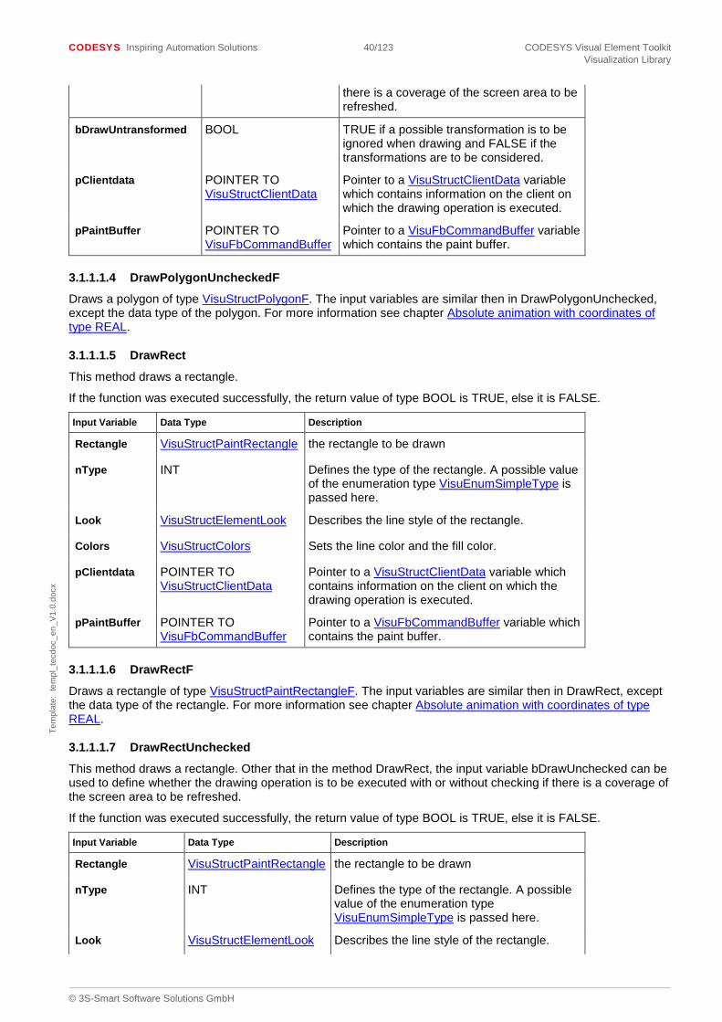
CODESYS Inspiring Automation Solutions 40/123 CODESYS Visual Element Toolkit Visualization Library
© 3S-Smart Software Solutions GmbH
Tem
plat
e: t
empl
_tec
doc_
en_V
1.0.
docx
there is a coverage of the screen area to be refreshed.
bDrawUntransformed BOOL TRUE if a possible transformation is to be ignored when drawing and FALSE if the transformations are to be considered.
pClientdata POINTER TO VisuStructClientData
Pointer to a VisuStructClientData variable which contains information on the client on which the drawing operation is executed.
pPaintBuffer POINTER TO VisuFbCommandBuffer
Pointer to a VisuFbCommandBuffer variable which contains the paint buffer.
3.1.1.1.4 DrawPolygonUncheckedF
Draws a polygon of type VisuStructPolygonF. The input variables are similar then in DrawPolygonUnchecked, except the data type of the polygon. For more information see chapter Absolute animation with coordinates of type REAL.
3.1.1.1.5 DrawRect
This method draws a rectangle.
If the function was executed successfully, the return value of type BOOL is TRUE, else it is FALSE.
Input Variable Data Type Description
Rectangle VisuStructPaintRectangle the rectangle to be drawn
nType INT Defines the type of the rectangle. A possible value of the enumeration type VisuEnumSimpleType is passed here.
Look VisuStructElementLook Describes the line style of the rectangle.
Colors VisuStructColors Sets the line color and the fill color.
pClientdata POINTER TO VisuStructClientData
Pointer to a VisuStructClientData variable which contains information on the client on which the drawing operation is executed.
pPaintBuffer POINTER TO VisuFbCommandBuffer
Pointer to a VisuFbCommandBuffer variable which contains the paint buffer.
3.1.1.1.6 DrawRectF
Draws a rectangle of type VisuStructPaintRectangleF. The input variables are similar then in DrawRect, except the data type of the rectangle. For more information see chapter Absolute animation with coordinates of type REAL.
3.1.1.1.7 DrawRectUnchecked
This method draws a rectangle. Other that in the method DrawRect, the input variable bDrawUnchecked can be used to define whether the drawing operation is to be executed with or without checking if there is a coverage of the screen area to be refreshed.
If the function was executed successfully, the return value of type BOOL is TRUE, else it is FALSE.
Input Variable Data Type Description
Rectangle VisuStructPaintRectangle the rectangle to be drawn
nType INT Defines the type of the rectangle. A possible value of the enumeration type VisuEnumSimpleType is passed here.
Look VisuStructElementLook Describes the line style of the rectangle.

CODESYS Inspiring Automation Solutions 41/123 CODESYS Visual Element Toolkit Visualization Library
© 3S-Smart Software Solutions GmbH
Tem
plat
e: t
empl
_tec
doc_
en_V
1.0.
docx
Input Variable Data Type Description
Colors VisuStructColors Sets the line color and the fill color.
bDrawUnchecked BOOL TRUE if the drawing operation is to be executed in any case and FALSE if the drawing operation is to be executed only if there is a coverage of the screen area to be refreshed.
pClientdata POINTER TO VisuStructClientData
Pointer to a VisuStructClientData variable which contains information on the client on which the drawing operation is executed.
pPaintBuffer POINTER TO VisuFbCommandBuffer
Pointer to a VisuFbCommandBuffer variable which contains the paint buffer.
3.1.1.1.8 DrawRectUncheckedF
Draws a rectangle of type VisuStructPaintRectangleF. The input variables are similar then in DrawRectUnchecked, except the data type of the rectangle. For more information see chapter Absolute animation with coordinates of type REAL.
3.1.1.1.9 DrawText
This method returns a text.
If the function was executed successfully, the return value of type BOOL is TRUE, else it is FALSE.
Input Variable Data Type Description
Rectangle VisuStructPaintRectangle Defines the rectangle which is to contain the text.
Font VisuStructFont Describes the font to be used.
pstText POINTER TO STRING Pointer to a string with the text to be returned.
bWstring BOOL TRUE if pstText points to a Unicode string (i.e. with 2 bytes per character), else FALSE.
dwFlags DWORD The text alignment and several other flags are passed in the text flags. See Textflag-Konstanten
pClientdata POINTER TO VisuStructClientData
Pointer to a VisuStructClientData variable which contains information on the client on which the drawing operation is executed.
pPaintBuffer POINTER TO VisuFbCommandBuffer
Pointer to a VisuFbCommandBuffer variable which contains the paint buffer.
3.1.1.1.10 DrawTextUnchecked
This method returns a text. Other that in the method DrawText, the input variable bDrawUnchecked can be used to define whether the drawing operation is to be executed with or without checking if there is a coverage of the screen area to be refreshed.
If the function was executed successfully, the return value of type BOOL is TRUE, else it is FALSE.
Input Variable Data Type Description
Rectangle VisuStructPaintRectangle Defines the rectangle which is to contain the text.
Font VisuStructFont Describes the font to be used.
pstText POINTER TO STRING Pointer to a string with the text to be returned.
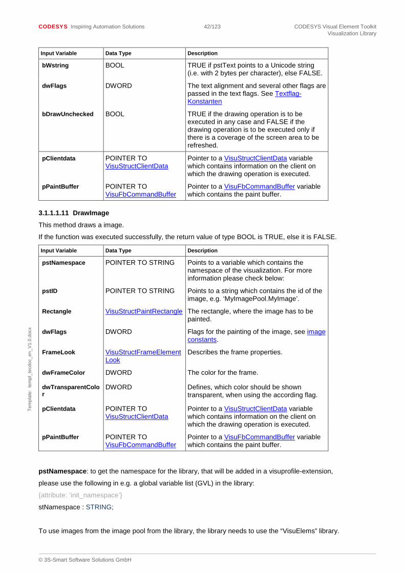
CODESYS Inspiring Automation Solutions 42/123 CODESYS Visual Element Toolkit Visualization Library
© 3S-Smart Software Solutions GmbH
Tem
plat
e: t
empl
_tec
doc_
en_V
1.0.
docx
Input Variable Data Type Description
bWstring BOOL TRUE if pstText points to a Unicode string (i.e. with 2 bytes per character), else FALSE.
dwFlags DWORD The text alignment and several other flags are passed in the text flags. See Textflag-Konstanten
bDrawUnchecked BOOL TRUE if the drawing operation is to be executed in any case and FALSE if the drawing operation is to be executed only if there is a coverage of the screen area to be refreshed.
pClientdata POINTER TO VisuStructClientData
Pointer to a VisuStructClientData variable which contains information on the client on which the drawing operation is executed.
pPaintBuffer POINTER TO VisuFbCommandBuffer
Pointer to a VisuFbCommandBuffer variable which contains the paint buffer.
3.1.1.1.11 DrawImage
This method draws a image.
If the function was executed successfully, the return value of type BOOL is TRUE, else it is FALSE.
Input Variable Data Type Description
pstNamespace POINTER TO STRING Points to a variable which contains the namespace of the visualization. For more information please check below:
pstID POINTER TO STRING Points to a string which contains the id of the image, e.g. ‘MyImagePool.MyImage’.
Rectangle VisuStructPaintRectangle The rectangle, where the image has to be painted.
dwFlags DWORD Flags for the painting of the image, see image constants.
FrameLook VisuStructFrameElementLook
Describes the frame properties.
dwFrameColor DWORD The color for the frame.
dwTransparentColor
DWORD Defines, which color should be shown transparent, when using the according flag.
pClientdata POINTER TO VisuStructClientData
Pointer to a VisuStructClientData variable which contains information on the client on which the drawing operation is executed.
pPaintBuffer POINTER TO VisuFbCommandBuffer
Pointer to a VisuFbCommandBuffer variable which contains the paint buffer.
pstNamespace: to get the namespace for the library, that will be added in a visuprofile-extension,
please use the following in e.g. a global variable list (GVL) in the library:
{attribute: ‘init_namespace’}
stNamespace : STRING;
To use images from the image pool from the library, the library needs to use the “VisuElems” library.

CODESYS Inspiring Automation Solutions 43/123 CODESYS Visual Element Toolkit Visualization Library
© 3S-Smart Software Solutions GmbH
Tem
plat
e: t
empl
_tec
doc_
en_V
1.0.
docx
More information of how to insert the library find here in the library manager passage.
3.1.1.1.12 DrawImageUnchecked
Other that in the method DrawImage, the input variable bDrawUnchecked can be used to define whether the drawing operation is to be executed with or without checking if there is a coverage of the screen area to be refreshed.
If the function was executed successfully, the return value of type BOOL is TRUE, else it is FALSE.
Input Variable Data Type Description
pstNamespace POINTER TO STRING Points to a variable which contains the namespace of the visualization. For more information please check below:
pstID POINTER TO STRING Points to a string which contains the id of the image, e.g. ‘MyImagePool.MyImage’.
Rectangle VisuStructPaintRectangle The rectangle, where the image has to be painted.
dwFlags DWORD Flags for the painting of the image, see image constants.
FrameLook VisuStructFrameElementLook
Describes the frame properties.
dwFrameColor DWORD The color for the frame.
dwTransparentColor
DWORD Defines, which color should be shown transparent, when using the according flag.
bDrawUnchecked BOOL TRUE if the drawing operation is to be executed in any case and FALSE if the drawing operation is to be executed only if there is a coverage of the screen area to be refreshed.
pClientdata POINTER TO VisuStructClientData
Pointer to a VisuStructClientData variable which contains information on the client on which the drawing operation is executed.
pPaintBuffer POINTER TO VisuFbCommandBuffer
Pointer to a VisuFbCommandBuffer variable which contains the paint buffer.
pstNamespace: to get the namespace for the library, that will be added in a visuprofile-extension,
please use the following in e.g. a global variable list (GVL) in the library:
{attribute: ‘init_namespace’}
stNamespace : STRING;
To use images from the image pool from the library, the library needs to use the “VisuElems” library.
More information of how to insert the library find here in the library manager passage.
3.1.1.1.13 DrawPie
This method draws a pie.
If the function was executed successfully, the return value of type BOOL is TRUE, else it is FALSE.
Input Variable Data Type Description
Rectangle VisuStructPaintRectangle The rectangle, where the pie has to be painted.

CODESYS Inspiring Automation Solutions 44/123 CODESYS Visual Element Toolkit Visualization Library
© 3S-Smart Software Solutions GmbH
Tem
plat
e: t
empl
_tec
doc_
en_V
1.0.
docx
Input Variable Data Type Description
startAngle INT Angle measured in degrees clockwise from the x-axis to the first side of the pie shape.
sweepAngle INT Angle measured in degrees clockwise from the startAngle parameter to the second side of the pie shape.
iType VisuEnumPieType Defines the type of the pie.
Look VisuStructElementLook Describes the line style of the pie.
Colors VisuStructColors Sets the line color and the fill color.
pClientdata POINTER TO VisuStructClientData
Pointer to a VisuStructClientData variable which contains information on the client on which the drawing operation is executed.
pPaintBuffer POINTER TO VisuFbCommandBuffer
Pointer to a VisuFbCommandBuffer variable which contains the paint buffer.
3.1.1.1.14 DrawPieUnchecked
This method draws a pie. Other that in the method DrawPie, the input variable bDrawUnchecked can be used to define whether the drawing operation is to be executed with or without checking if there is a coverage of the screen area to be refreshed.
If the function was executed successfully, the return value of type BOOL is TRUE, else it is FALSE.
Input Variable Data Type Description
Rectangle VisuStructPaintRectangle
The rectangle, where the pie has to be painted.
startAngle INT Angle measured in degrees clockwise from the x-axis to the first side of the pie shape.
sweepAngle INT Angle measured in degrees clockwise from the startAngle parameter to the second side of the pie shape.
iType VisuEnumPieType Defines the type of the pie.
Look VisuStructElementLook Describes the line style of the pie.
Colors VisuStructColors Sets the line color and the fill color.
bDrawUnchecked BOOL TRUE if the drawing operation is to be executed in any case and FALSE if the drawing operation is to be executed only if there is a coverage of the screen area to be refreshed.
bDrawUntransformed BOOL TRUE if a possible transformation is to be ignored when drawing and FALSE if the transformations are to be considered.
pClientdata POINTER TO VisuStructClientData
Pointer to a VisuStructClientData variable which contains information on the client on which the drawing operation is executed.
pPaintBuffer POINTER TO VisuFbCommandBuffer
Pointer to a VisuFbCommandBuffer variable which contains the paint buffer.

CODESYS Inspiring Automation Solutions 45/123 CODESYS Visual Element Toolkit Visualization Library
© 3S-Smart Software Solutions GmbH
Tem
plat
e: t
empl
_tec
doc_
en_V
1.0.
docx
3.1.1.1.15 ExecuteProgram
This method executes a program on the controller.
If the function was executed successfully, the return value of type BOOL is TRUE, else it is FALSE.
Input Variable Data Type Description
pstProg POINTER TO STRING Pointer to a string which contains the program to be executed.
pstArguments POINTER TO STRING Pointer to a string which contains the program arguments.
pPaintBuffer POINTER TO VisuFbCommandBuffer
Pointer to a VisuFbCommandBuffer variable which contains the paint buffer.
3.1.1.1.16 GetCurrentClipRect
This method returns the currently active clipping rectangle.
If the function was executed successfully, the return value of type BOOL is TRUE, else it is FALSE.
Input Variable Data Type Description
pRect POINTER TO VisuStructSimpleRectangle
Pointer to a VisuStructSimpleRectangle variable which contains the current clipping rectangle.
3.1.1.1.17 GetCurrentTransformation
This method returns the currently set transformation (translation, scale).
The return value of type VisuFbTransformInformation describes the currently set transformation.
3.1.1.1.18 IsToUpdatePolygon
This methods checks whether a frequency polygon must be redrawn.
The return value of type BOOL is TRUE if the frequency polygon must be redrawn, else it is FALSE.
Input Variable Data Type Description
Polygon VisuStructPolygon VisuStructPolygon variable which describes the frequency polygon to be checked.
pClientdata POINTER TO VisuStructClientData
Pointer to a VisuStructClientData variable which contains information on the client on which the drawing operation is executed.
nLineWidth INT Line width of the frequency polygon.
3.1.1.1.19 IsToUpdateRectangle
This method checks whether a rectangle must be redrawn.
The return value of type BOOL is TRUE if the rectangle must be redrawn, else it is FALSE.
Input Variable Data Type Description
Rectangle VisuStructPaintRectangle VisuStructPaintRectangle variable which describes the rectangle to be checked.
pClientdata POINTER TO VisuStructClientData
Pointer to a VisuStructClientData variable which contains information on the client on which the drawing operation is executed.
3.1.1.1.20 OpenLocalFileDialog
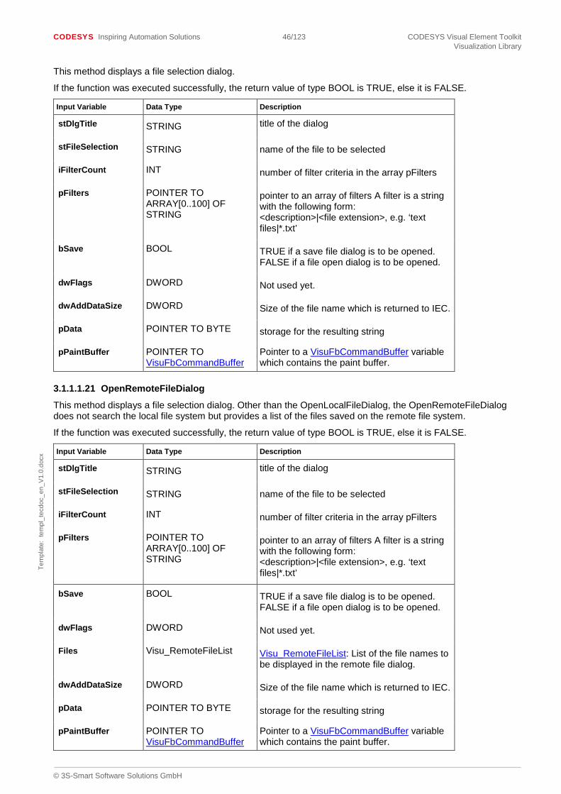
CODESYS Inspiring Automation Solutions 46/123 CODESYS Visual Element Toolkit Visualization Library
© 3S-Smart Software Solutions GmbH
Tem
plat
e: t
empl
_tec
doc_
en_V
1.0.
docx
This method displays a file selection dialog.
If the function was executed successfully, the return value of type BOOL is TRUE, else it is FALSE.
Input Variable Data Type Description
stDlgTitle STRING title of the dialog
stFileSelection STRING name of the file to be selected
iFilterCount INT number of filter criteria in the array pFilters
pFilters POINTER TO ARRAY[0..100] OF STRING
pointer to an array of filters A filter is a string with the following form: <description>|<file extension>, e.g. ‘text files|*.txt’
bSave BOOL TRUE if a save file dialog is to be opened. FALSE if a file open dialog is to be opened.
dwFlags DWORD Not used yet.
dwAddDataSize DWORD Size of the file name which is returned to IEC.
pData POINTER TO BYTE storage for the resulting string
pPaintBuffer POINTER TO VisuFbCommandBuffer
Pointer to a VisuFbCommandBuffer variable which contains the paint buffer.
3.1.1.1.21 OpenRemoteFileDialog
This method displays a file selection dialog. Other than the OpenLocalFileDialog, the OpenRemoteFileDialog does not search the local file system but provides a list of the files saved on the remote file system.
If the function was executed successfully, the return value of type BOOL is TRUE, else it is FALSE.
Input Variable Data Type Description
stDlgTitle STRING title of the dialog
stFileSelection STRING name of the file to be selected
iFilterCount INT number of filter criteria in the array pFilters
pFilters POINTER TO ARRAY[0..100] OF STRING
pointer to an array of filters A filter is a string with the following form: <description>|<file extension>, e.g. ‘text files|*.txt’
bSave BOOL TRUE if a save file dialog is to be opened. FALSE if a file open dialog is to be opened.
dwFlags DWORD Not used yet.
Files Visu_RemoteFileList Visu_RemoteFileList: List of the file names to be displayed in the remote file dialog.
dwAddDataSize DWORD Size of the file name which is returned to IEC.
pData POINTER TO BYTE storage for the resulting string
pPaintBuffer POINTER TO VisuFbCommandBuffer
Pointer to a VisuFbCommandBuffer variable which contains the paint buffer.

CODESYS Inspiring Automation Solutions 47/123 CODESYS Visual Element Toolkit Visualization Library
© 3S-Smart Software Solutions GmbH
Tem
plat
e: t
empl
_tec
doc_
en_V
1.0.
docx
3.1.1.1.22 PopTransformation
This method removes the transformations recently set with PushTransformation. The parameter values need to be the same, as set in PushTransformation, to undo the transformation.
If the function was executed successfully, the return value of type BOOL is TRUE, else it is FALSE.
Input Variable Data Type Description
ptMother VisuStructPoint This point defines the scaling of the drawing elements. If no scaling is intended, this point should be set to the size of the destination rectangle (rectPosition): ptMother.iX := iWidthDestination; ptMother.iY := iHeightDestination; For scaling set ptMother accordingly.
rectPosition VisuStructSimpleRectangle Rectangle circumscribing the object to be embedded, means the destination rectangle. This defines the movement of the elements.
bIso BOOL TRUE if the transformation is to be executed isotropically. FALSE for anisotropically. Needed, when original rectangle and destination rectangle differ in proportions.
bFixed BOOL TRUE for a fixed transformation. This means the object is only translated in the X and Y direction (moved, but not scaled, ptMother is ignored) FALSE: value of ptMother will be used.
bClip BOOL TRUE if the object to be embedded is to be clipped in case it goes beyond the edges of the image. This can happen, if ptMother (scaling factor) is not set correct, regarding the size of the original and the destination rectangle.
pPaintBuffer POINTER TO VisuFbCommandBuffer
Pointer to a VisuFbCommandBuffer variable which contains the paint buffer.
3.1.1.1.23 PushTransformation
This method sets a transformation on the transformation stack. The method includes moving and scaling of one or more drawing elements. First set the PushTransformation, than add all the drawing elements, which should be transformed. Finally remove the transformation again with PopTransformation.
If the function was executed successfully, the return value of type BOOL is TRUE, else it is FALSE.
Input Variable Data Type Description
ptMother VisuStructPoint This point defines the scaling of the drawing elements. If no scaling is intended, this point should be set to the size of the destination rectangle (rectPosition): ptMother.iX := iWidthDestination; ptMother.iY := iHeightDestination; For scaling set ptMother accordingly.
rectPosition VisuStructSimpleRectangle Rectangle circumscribing the object to be embedded, means the destination rectangle. This defines the movement of the elements.

CODESYS Inspiring Automation Solutions 48/123 CODESYS Visual Element Toolkit Visualization Library
© 3S-Smart Software Solutions GmbH
Tem
plat
e: t
empl
_tec
doc_
en_V
1.0.
docx
Input Variable Data Type Description
bIso BOOL TRUE if the transformation is to be executed isotropically. FALSE for anisotropically. Needed, when original rectangle and destination rectangle differ in proportions.
bFixed BOOL TRUE for a fixed transformation. This means the object is only translated in the X and Y direction (moved, but not scaled, ptMother is ignored) FALSE: value of ptMother will be used.
bClip BOOL TRUE if the object to be embedded is to be clipped in case it goes beyond the edges of the image. This can happen, if ptMother (scaling factor) is not set correct, regarding the size of the original and the destination rectangle.
pPaintBuffer POINTER TO VisuFbCommandBuffer
Pointer to a VisuFbCommandBuffer variable which contains the paint buffer.
3.1.1.1.24 SetFill
This method sets the style for the subsequent area fillings.
If the function was executed successfully, the return value of type BOOL is TRUE, else it is FALSE.
Input Variable Data Type Description
pLook POINTER TO VisuStructElementLook
Pointer to a VisuStructElementLook variable which contains the filling style.
pColors POINTER TO VisuStructColors
Pointer to a VisuStructColors variable which contains the fill color to be used.
pPaintBuffer POINTER TO VisuFbCommandBuffer
Pointer to a VisuFbCommandBuffer variable which contains the paint buffer.
3.1.1.1.25 SetFont
This method defines the font to be used for the subsequent drawing operations.
If the function was executed successfully, the return value of type BOOL is TRUE, else it is FALSE.
Input Variable Data Type Description
pFont POINTER TO VisuStructFont
the font to be used
pPaintBuffer POINTER TO VisuFbCommandBuffer
Pointer to a VisuFbCommandBuffer variable which contains the paint buffer.
3.1.1.1.26 SetLine
This method defines the line style to be used for the subsequent drawing operations.
If the function was executed successfully, the return value of type BOOL is TRUE, else it is FALSE.
Input Variable Data Type Description
pLook POINTER TO VisuStructElementLook
Describes the line style of the rectangle.

CODESYS Inspiring Automation Solutions 49/123 CODESYS Visual Element Toolkit Visualization Library
© 3S-Smart Software Solutions GmbH
Tem
plat
e: t
empl
_tec
doc_
en_V
1.0.
docx
pColors POINTER TO VisuStructColors
describes the line color
pPaintBuffer POINTER TO VisuFbCommandBuffer
Pointer to a VisuFbCommandBuffer variable which contains the paint buffer.
3.1.1.1.27 SetRenderLocation
This method defines the render location of the subsequent drawing commands.
If the function was executed successfully, the return value of type BOOL is TRUE, else it is FALSE.
Input Variable Data Type Description
loc Visu_RenderLocation Defines where the subsequent drawing operations are to be executed.
pClientdata POINTER TO VisuStructClientData
Pointer to a VisuStructClientData variable which contains information on the client on which the drawing operation is executed.
3.1.1.1.28 SetTransformation
This method sets the transformation to be used for the subsequent drawing operations. To reset the transformation to the original one, you need to store the original transformation first, then set a new transformation. In most cases, it is easier to use PushTransformation and PopTransformation.
The return value of type VisuFbTransformInformation describes the currently set transformation.
Input Variable Data Type Description
newTransform VisuFbTransformInformation Describes the transformation to be set.
3.1.1.1.29 TransformPaintRect
This method transforms the coordinates of a rectangle in consideration of the transformation set with the method SetTransformation.
The return value of type VisuStructPaintRectangle contains the coordinates of the rectangle after the transformation.
Input Variable Data Type Description
rect VisuStructPaintRectangle the rectangle to be transformed
3.1.1.1.30 TransformPolygon
This method transforms the coordinates of a frequency polygon in consideration of the transformation set with the method SetTransformation.
If the function was executed successfully, the return value of type BOOL is TRUE, else it is FALSE.
Input Variable Data Type Description
poly VisuStructPolygon the frequency polygon to be transformed The transformation takes place directly on this input variable.
3.1.2 IdrawingInterface2
The interface IdrawingInterface2 extends the interface IdrawingInterface giving it the capability to draw buttons.
3.1.2.1 Methods
3.1.2.1.1 DrawButtonOnClient
This method draws a button.

CODESYS Inspiring Automation Solutions 50/123 CODESYS Visual Element Toolkit Visualization Library
© 3S-Smart Software Solutions GmbH
Tem
plat
e: t
empl
_tec
doc_
en_V
1.0.
docx
If the function was executed successfully, the return value of type BOOL is TRUE, else it is FALSE.
Input Variable Data Type Description
bHighButton BOOL If this variable is TRUE the variable iColorCount is evaluated, if it is FALSE it is not.
bPressed BOOL TRUE if the button is to be displayed as pressed, else FALSE.
iColorCount INT This variable is only evaluated if bHighButton is TRUE. This variable defines the pixel width of the light lines and shadow lines of the button.
rPosition VisuStructPaintRectangle The VisuStructPaintRectangle variable describes the position of the button.
bDrawUnchecked BOOL TRUE if the drawing operation is to be executed in any case and FALSE if the drawing operation is to be executed only if there is a coverage of the screen area to be refreshed.
pClientdata POINTER TO VisuStructClientData
Pointer to a VisuStructClientData variable which contains information on the client on which the drawing operation is executed.
pPaintBuffer POINTER TO VisuFbCommandBuffer
Pointer to a VisuFbCommandBuffer variable which contains the paint buffer.
Output Variable Data Type Description
colors Visu_StructButtonColors Contains the colors used to draw the button.
3.1.3 NativeControl
In the following section the handling with native controls is described.
3.1.3.1 Visu_FbNativeControlManager
This function block is used to register and handle native controls.
3.1.3.1.1 RegisterNativeControl
Call RegisterNativeControl in the Initialize Method of the specific native control element.
Input Variable Data Type Description
element IvisualElement visualization element
dwID DWORD The ID which was given by the RegisterNativeControl or 16#FFFFFFFF if the control should be registered.
bReRegister BOOL If TRUE the element interface is registered newly.
3.1.3.1.2 AddHideId
The element can call AddHideId from the NativeControlManager when the native control should be hidden for a specific client. Sometimes the element does not have the render context when the hide event should be executed, e.g. VISU_ELEMINFO_VISUVISIBILITY:

CODESYS Inspiring Automation Solutions 51/123 CODESYS Visual Element Toolkit Visualization Library
© 3S-Smart Software Solutions GmbH
Tem
plat
e: t
empl
_tec
doc_
en_V
1.0.
docx
g_NativeControlManager.AddHideId(m_dwID, m_pCurrentClientData);
Input Variable Data Type Description
dwID DWORD The unique ID which was given by the NativeControlManager
pClientdata POINTER TO VisuStructClientData
Pointer to a VisuStructClientData variable which contains information on the client on which the drawing operation is executed.
3.1.3.2 InativeControlInterface
The interface to the NativeControl methods can be used to create, move, show and call methods on a native control. A native control is a target specific control which must be installed on the target device. It is created on top of the visualization.
3.1.3.2.1 CreateNativeControl
This method creates a native control. First of all the native control must be registered in the NativeControlManager. The NativeControlManger returns a unique id for the control which is zero based.
M_dwID := g_NativeControlManager.RegisterNativeControl(m_IVE, m_dwID, TRUE);
Input Variable Data Type Description
pstControl POINTER TO STRING The control name.
dwID DWORD The unique ID which was given by the NativeControlManager
pRect POINTER TO VisuStructSimpleRectangle
The rectangle where the control should be opened.
pPaintBuffer POINTER TO VisuFbCommandBuffer
Pointer to a VisuFbCommandBuffer variable which contains the paint buffer.
3.1.3.2.2 CallNativeControlMethod
This method calls a method in the native control. The function block VisuFbAnalyzeParameterList should be used in combination with this method. An instance of this FB should be created and the method AddCallNativeControlMethod should be called.
Input Variable Data Type Description
dwID DWORD The unique ID which was given by the NativeControlManager
dwMethodID DWORD The method ID.
pstMethod POINTER TO STRING The method name.
pParameters POINTER TO VisuFbAnalyzeParameterList
The method parameters.
pResultParameter POINTER TO VisuFbAnalyzeParameter
The result parameter of this method.
3.1.3.2.3 MoveNativeControl
This method moves the native control.

CODESYS Inspiring Automation Solutions 52/123 CODESYS Visual Element Toolkit Visualization Library
© 3S-Smart Software Solutions GmbH
Tem
plat
e: t
empl
_tec
doc_
en_V
1.0.
docx
Input Variable Data Type Description
dwID DWORD The unique ID which was given by the NativeControlManager
pRect POINTER TO VisuStructSimpleRectangle
The rectangle where the control should be moved to.
pPaintBuffer POINTER TO VisuFbCommandBuffer
Pointer to a VisuFbCommandBuffer variable which contains the paint buffer.
3.1.3.2.4 ShowNativeControl
This method shows or hides the native control.
Input Variable Data Type Description
dwID DWORD The unique ID which was given by the NativeControlManager
dwFlags DWORD The flags if the native control should be shown or hidden.
VISU_SHOWNATIVECONTROL_SHOW: DWORD := 16#00000001;
VISU_SHOWNATIVECONTROL_HIDE: DWORD := 16#00000002;
VISU_SHOWNATIVECONTROL_HIDE_AND_DESTROY: DWORD := 16#00000004;
pPaintBuffer POINTER TO VisuFbCommandBuffer
Pointer to a VisuFbCommandBuffer variable which contains the paint buffer.
3.1.4 Iselectable
The interface Iselectable is used by a visualization element to implement the methods required to be able to react to keyboard input and change the selection with the keyboard.
3.1.4.1 Methods
3.1.4.1.1 IsSelectable
This method checks whether an element can be selected.
The return value of type BOOL is TRUE if the element can be selected, otherwise it is FALSE.
3.1.4.1.2 PaintSelection
This method executes the required drawing commands to draw the current element selection.
The return value type BOOL – The return value is not of importance yet.
Input Variable Data Type Description
pCurrentSelectionData POINTER TO Visu_StructSelectionData
current selection data
selectionColors VisuStructColors color to be used
selectionLook VisuStructElementLook line style to be used
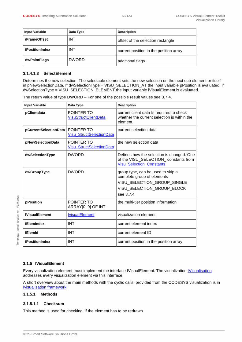
CODESYS Inspiring Automation Solutions 53/123 CODESYS Visual Element Toolkit Visualization Library
© 3S-Smart Software Solutions GmbH
Tem
plat
e: t
empl
_tec
doc_
en_V
1.0.
docx
Input Variable Data Type Description
iFrameOffset INT offset of the selection rectangle
iPositionIndex INT current position in the position array
dwPaintFlags DWORD additional flags
3.1.4.1.3 SelectElement
Determines the new selection. The selectable element sets the new selection on the next sub element or itself in pNewSelectionData. If dwSelectionType = VISU_SELECTION_AT the input variable pPosition is evaluated, if dwSelectionType = VISU_SELECTION_ELEMENT the input variable iVisualElement is evaluated.
The return value of type DWORD – For one of the possible result values see 3.7.4.
Input Variable Data Type Description
pClientdata POINTER TO VisuStructClientData
current client data Is required to check whether the current selection is within the element.
pCurrentSelectionData POINTER TO Visu_StructSelectionData
current selection data
pNewSelectionData POINTER TO Visu_StructSelectionData
the new selection data
dwSelectionType DWORD Defines how the selection is changed. One of the VISU_SELECTION_ constants from Visu_Selection_Constants
dwGroupType DWORD group type, can be used to skip a complete group of elements VISU_SELECTION_GROUP_SINGLE VISU_SELECTION_GROUP_BLOCK see 3.7.4
pPosition POINTER TO ARRAY[0..9] OF INT
the multi-tier position information
iVisualElement IvisualElement visualization element
iElemIndex INT current element index
iElemId INT current element ID
iPositionIndex INT current position in the position array
3.1.5 IVisualElement
Every visualization element must implement the interface IVisualElement. The visualization IVisualisation addresses every visualization element via this interface.
A short overview about the main methods with the cyclic calls, provided from the CODESYS visualization is in Ivisualization framework.
3.1.5.1 Methods
3.1.5.1.1 Checksum
This method is used for checking, if the element has to be redrawn.

CODESYS Inspiring Automation Solutions 54/123 CODESYS Visual Element Toolkit Visualization Library
© 3S-Smart Software Solutions GmbH
Tem
plat
e: t
empl
_tec
doc_
en_V
1.0.
docx
Add up the checksum for the values, that can change and will render the drawing, like the variable value. Use VisuFctAddChecksum for this. The return value is the checksum as VisuTypeChecksum. This value is used in the method GetUpdateRects.
3.1.5.1.2 ContainsPoint
This method determines whether the visualization element contains the passed point.
The return value of type BOOL is TRUE if the visualization element contains the point, else it is FALSE.
Input Variable Data Type Description
Pt VisuStructPoint the point to be checked
3.1.5.1.3 Destruct
This method can be used to delete dynamically allocated memory.
If the function was executed successfully, the return value of type BOOL is TRUE, else it is FALSE.
3.1.5.1.4 ElementInfo
This method is used by the visualization as a generic method to query certain information from visualization elements or to provide the elements with information such as the number of embedded visualization elements or the fact that an element has become visible.
See Visu_ElementInfo_Constants
Example:
IF (pData^.iRequestedInfo = VisuElems.VISU_ELEMINFO_VISUVISIBILITY) THEN
IF pData^.dwParam1 = 1 OR pData^.dwParam1 = 3 THEN
// The element was made visible by a visualization change or a frame change.
bActivate := TRUE;
ELSE
bDeactivate := TRUE;
END_IF
END_IF
The return value of type INT indicates whether the call was executed successfully and should be one of the following values:
- VISU_ELEMINFO_SERVICE_HANDLED_OK: call executed successfully
- VISU_ELEMINFO_SERVICE_HANDLED_ERROR_GENERAL: error
- VISU_ELEMINFO_SERVICE_HANDLED_ERROR_PARAMETER: invalid parameter passed
- VISU_ELEMINFO_SERVICE_UNKNOWN: unknown value in Visu_StructElementInfo.iRequestedInfo
Input Variable Data Type Description
pData Visu_StructElementInfo Pointer to a Visu_StructElementInfo variable which contains information to be passed.
3.1.5.1.5 GetClientData
This method provides information on the client which displays the visualization.
The return value of type POINTER TO VisuStructClientData contains information on the client, on which the drawing operation is executed.
3.1.5.1.6 GetSurroundingRect
This method provides the smallest rectangle which completely encloses a given visualization element.
The return value of type VisuStructSimpleRectangle describes this rectangle. Normally the function VisuFctPaintRectCalculateSurroundingRect is used to calculate the rectangle.

CODESYS Inspiring Automation Solutions 55/123 CODESYS Visual Element Toolkit Visualization Library
© 3S-Smart Software Solutions GmbH
Tem
plat
e: t
empl
_tec
doc_
en_V
1.0.
docx
3.1.5.1.7 GetTextProperties
This method returns information on the text properties.
If the function was executed successfully, the return value of type BOOL is TRUE, else it is FALSE.
Input Variable Data Type Description
pFont POINTER TO VisuStructFont
Describes the font to be used.
pOptAlignment POINTER TO DWORD Returns the horizontal and vertical text alignment. The DWORD value is a bit-by-bit OR link of the VisuEnumHorizontalAlignment value and the VisuEnumVerticalAlignment value.
pFlags POINTER TO DWORD More information can be passed here. Optional
3.1.5.1.8 GetText
This method returns the element text.
The return value of type Visu_TypeString is a pointer to the variable which contains the text.
3.1.5.1.9 GetTooltip
This method returns the tooltip of the element.
The return value of type Visu_TypeString is a pointer to the variable which contains the tooltip.
3.1.5.1.10 GetUpdateRects
This method determines which parts of the screen have to be redrawn/updated for the visualization element. These rectangle screens are made known to the visualization with the call
VisuStructClientData.GlobalData.CurrentUpdateRects.AddSimpleRect
Please note:
The method Checksum which calculates a checksum of the current dynamic state of the element, should be called in this function. If the checksum differs from the previous one, the element must be updated.
See example visualization element VisuFbElemSliderExample in the example library.
Checksumx := Checksum ();
pElementry := ADR (m_pCurrentClientData^.ElementsData.pElementsEntry^[elemIndex]);
IF checksumx <> pElementry^.OldChecksum THEN
…
If the function was executed successfully, the return value of type BOOL is TRUE, else it is FALSE.
Input Variable Data Type Description
elemIndex INT An INT which describes the position of the visualization element within the visualization elements.
3.1.5.1.11 HandleInput
This method handles an event.
If the event was handled successfully the return value of type BOOL is TRUE, else it is FALSE.
Input Variable Data Type Description
pEvent VisuStructEvent Contains the description of the event to be handled.

CODESYS Inspiring Automation Solutions 56/123 CODESYS Visual Element Toolkit Visualization Library
© 3S-Smart Software Solutions GmbH
Tem
plat
e: t
empl
_tec
doc_
en_V
1.0.
docx
3.1.5.1.12 Initialize
This method initializes the visualization element.
If the function was executed successfully, the return value of type BOOL is TRUE, else it is FALSE.
Input Variable Data Type Description
parentVisu Ivisualisation A Ivisualisation instance the visualization element is embedded into. Normally, the visualization element saves this instance in a local visualization element variable for subsequent processing (e.g. in update)
3.1.5.1.13 Paint
This method draws the visualization element.
If the function was executed successfully, the return value of type BOOL is TRUE, else it is FALSE.
Input Variable Data Type Description
dwFlags DWORD Contains information on the current draw state. Is required for a subsequent call of the function VisuFctIsElementToDraw.
3.1.5.1.14 SetClientData
This method is needed to store information on the client which displays the visualization in the visualization element. This information is required for subsequent calls of the methods Update, GetUpdateRects, Paint and HandleInput.
The return value of type BOOL is irrelevant and is therefore not 56verridd.
Input Variable Data Type Description
pClientdata POINTER TO VisuStructClientData
Pointer to a VisuStructClientData variable which contains information on the client on which the drawing operation is executed.
3.1.5.1.15 SetStaticState
This method sets a local variable in the visualization element. This variable stores whether the element is static (TRUE) or dynamic (FALSE). This variable is required later on in the method paint when the function VisuFctIsElementToDraw is called.
If the function was executed successfully, the return value of type BOOL is TRUE, else it is FALSE.
3.1.5.1.16 Update
This method updates the internal state of the visualization element. The local function block variables which are overridden in the subsequent paint operation (method paint) should be set in this method.
If the function was executed successfully, the return value of type BOOL is TRUE, else it is FALSE.
3.1.6 IVisualElement3
An optional extension of IVisualElement. Nevertheless, it is recommended, to implement this interface.
3.1.6.1 Methods
3.1.6.1.1 GetCompleteSurroundingRect
Similar to GetSurroundingRect of IVisualElement. As this method is intended to being used for adjusting frame outlines and scrolling borders, the exact size that is painted to by the element has to be returned. This means, the size must consider possible outer frame line widths, which might enlarge the element as well as considering rotation of the element or acute angles within polygons.
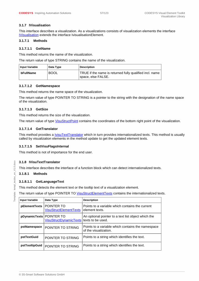
CODESYS Inspiring Automation Solutions 57/123 CODESYS Visual Element Toolkit Visualization Library
© 3S-Smart Software Solutions GmbH
Tem
plat
e: t
empl
_tec
doc_
en_V
1.0.
docx
3.1.7 IVisualisation
This interface describes a visualization. As a visualizations consists of visualization elements the interface IVisualisation extends the interface IvisualisationElement.
3.1.7.1 Methods
3.1.7.1.1 GetName
This method returns the name of the visualization.
The return value of type STRING contains the name of the visualization.
Input Variable Data Type Description
bFullName BOOL TRUE if the name is returned fully qualified incl. name space, else FALSE.
3.1.7.1.2 GetNamespace
This method returns the name space of the visualization.
The return value of type POINTER TO STRING is a pointer to the string with the designation of the name space of the visualization.
3.1.7.1.3 GetSize
This method returns the size of the visualization.
The return value of type VisuStructPoint contains the coordinates of the bottom right point of the visualization.
3.1.7.1.4 GetTranslator
This method provides a IvisuTextTranslator which in turn provides internationalized texts. This method is usually called by visualization elements in the method update to get the updated element texts.
3.1.7.1.5 SetVisuFlagsInternal
This method is not of importance for the end user.
3.1.8 IVisuTextTranslator
This interface describes the interface of a function block which can detect internationalized texts.
3.1.8.1 Methods
3.1.8.1.1 GetLanguageText
This method detects the element text or the tooltip text of a visualization element.
The return value of type POINTER TO VisuStructElementTexts contains the internationalized texts.
Input Variable Data Type Description
pElementTexts POINTER TO VisuStructElementTexts
Points to a variable which contains the current element texts.
pDynamicTexts POINTER TO VisuStructDynamicTexts
An optional pointer to a text list object which the texts to be used.
pstNamespace POINTER TO STRING Points to a variable which contains the namespace of the visualization.
pstTextGuid POINTER TO STRING Points to a string which identifies the text.
pstTooltipGuid POINTER TO STRING Points to a string which identifies the text.
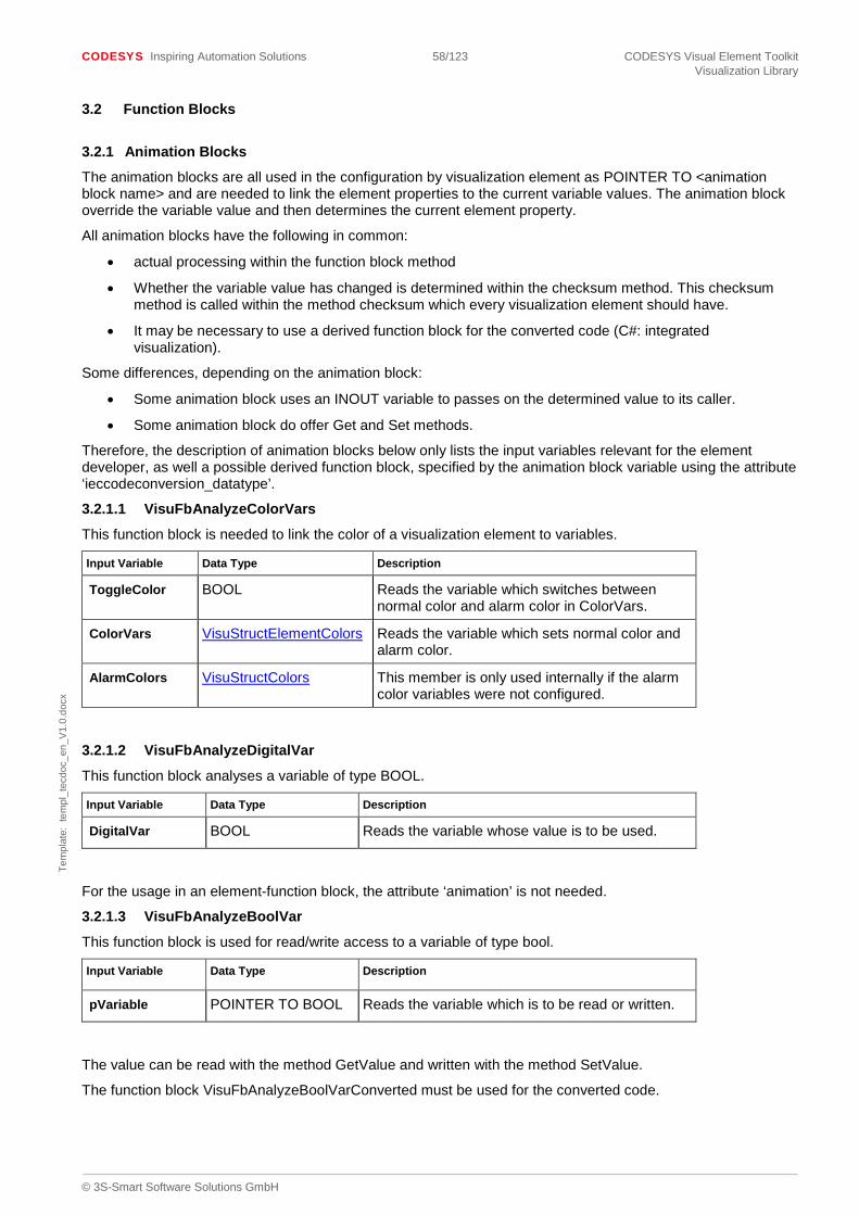
CODESYS Inspiring Automation Solutions 58/123 CODESYS Visual Element Toolkit Visualization Library
© 3S-Smart Software Solutions GmbH
Tem
plat
e: t
empl
_tec
doc_
en_V
1.0.
docx
3.2 Function Blocks
3.2.1 Animation Blocks
The animation blocks are all used in the configuration by visualization element as POINTER TO <animation block name> and are needed to link the element properties to the current variable values. The animation block override the variable value and then determines the current element property.
All animation blocks have the following in common:
• actual processing within the function block method
• Whether the variable value has changed is determined within the checksum method. This checksum method is called within the method checksum which every visualization element should have.
• It may be necessary to use a derived function block for the converted code (C#: integrated visualization).
Some differences, depending on the animation block:
• Some animation block uses an INOUT variable to passes on the determined value to its caller.
• Some animation block do offer Get and Set methods.
Therefore, the description of animation blocks below only lists the input variables relevant for the element developer, as well a possible derived function block, specified by the animation block variable using the attribute ‘ieccodeconversion_datatype’.
3.2.1.1 VisuFbAnalyzeColorVars
This function block is needed to link the color of a visualization element to variables.
Input Variable Data Type Description
ToggleColor BOOL Reads the variable which switches between normal color and alarm color in ColorVars.
ColorVars VisuStructElementColors Reads the variable which sets normal color and alarm color.
AlarmColors VisuStructColors This member is only used internally if the alarm color variables were not configured.
3.2.1.2 VisuFbAnalyzeDigitalVar
This function block analyses a variable of type BOOL.
Input Variable Data Type Description
DigitalVar BOOL Reads the variable whose value is to be used.
For the usage in an element-function block, the attribute ‘animation’ is not needed.
3.2.1.3 VisuFbAnalyzeBoolVar
This function block is used for read/write access to a variable of type bool.
Input Variable Data Type Description
pVariable POINTER TO BOOL Reads the variable which is to be read or written.
The value can be read with the method GetValue and written with the method SetValue.
The function block VisuFbAnalyzeBoolVarConverted must be used for the converted code.

CODESYS Inspiring Automation Solutions 59/123 CODESYS Visual Element Toolkit Visualization Library
© 3S-Smart Software Solutions GmbH
Tem
plat
e: t
empl
_tec
doc_
en_V
1.0.
docx
3.2.1.4 VisuFbAnalyzeLookVars
This function block is used to determine the line style and the area fill style from variables.
Input Variable Data Type Description
LookVars VisuStructElementLook Reads the variables which set the line width, line style and the area fill style.
3.2.1.5 VisuFbAnalyzeNumVar
This function block is used to read/write access any given numeric variable. The visualization element scrollbar uses this function block to determine the scrollbar value, maximum, minimum and page size from variables.
Input Variable Data Type Description
pVarNumber POINTER TO DWORD
Reads the variable which is to be read or written.
The value can be read with the method GetValue and written with the method SetValue.
The function block VisuFbAnalyzeNumVarConverted must be used for the converted code.
3.2.1.6 VisuFbAnalyzeStateVars
This function block is used to determine the current state of the element from variables.
Input Variable Data Type Description
State VisuStructElementState Reads the variables which determine the visibility or the behaviour upon input.
3.2.1.7 VisuFbAnalyzeTextPropertyVars
This function block is used to determine the properties of the font to be used from variables.
Input Variable Data Type Description
FontProperties VisuStructFont Reads the variables which determine the font, the font size, the font style etc.
3.2.1.8 VisuFbAnalyzeTextVars
This function block is used to determine the value of the element text or the element tooltip from variables.
Input Variable Data Type Description
pVarText POINTER TO DWORD
Reads the variable which determined the element text.
pVarTooltip POINTER TO DWORD
Reads the variable which determined the element tooltip.
The function block VisuFbAnalyzeTextVarsConverted must be used for the converted code.
3.2.1.9 VisuFbMoveAbsolute
This function block is used to determine the position of a visualization element from variables.
Input Variable Data Type Description
Data VisuStructMoveAbsoluteData
Reads the variables which determine the position, the rotation and the scale.

CODESYS Inspiring Automation Solutions 60/123 CODESYS Visual Element Toolkit Visualization Library
© 3S-Smart Software Solutions GmbH
Tem
plat
e: t
empl
_tec
doc_
en_V
1.0.
docx
The element position is updated, according the current values, by calling the method execute. The result will be returned in the input-variable EffectivePoints.
3.2.1.10 VisuFbMoveAbsoluteF
Similar to VisuFbMoveAbsolute, this function block is used to move a element and determine its position. Additional, the variables, that define the movement and the resulting new position are of type REAL.
This function block can only be used with devices, that support paint commands with real-coordinates.
Input Variable Data Type Description
Data VisuStructMoveAbsoluteDataF
Reads the variables which determine the position, the rotation and the scale.
The element position is updated, according the current values, by calling the method execute. Here, the inputvalues are coordinates of type INT, from the static position of the element. The result of execute is available by the Get-methods.
3.2.1.11 VisuFbMoveRelative
This function block is used to determine the position and size of a visualization element from variables.
Input Variable Data Type Description
MoveTopLeftBy VisuStructPoint Reads the variable which determines to where the top left corner of the visualization element is to be moved.
MoveBottomRightBy VisuStructPoint Reads the variable which determines to where the bottom right corner of the visualization element is to be moved.
3.2.1.12 VisuFbAnalyzeParameter
This function block should be used in combination with the NativeControlInterface CallNativeControlMethod
Input Variable Data Type Description
pVar POINTER TO DWORD
The pointer to the parameter variable.
dwVarType DWORD The variable type.
dwVarSize DWORD The size of the variable.
3.2.1.13 VisuFbAnalyzeParameterList
This function block should be used in combination with the NativeControlInterface CallNativeControlMethod
Input Variable Data Type Description
Parameters POINTER TO ARRAY [0..255] OF VisuFbAnalyzeParameter
The parameters for the function call.
iParameterCount INT The parameter count.

CODESYS Inspiring Automation Solutions 61/123 CODESYS Visual Element Toolkit Visualization Library
© 3S-Smart Software Solutions GmbH
Tem
plat
e: t
empl
_tec
doc_
en_V
1.0.
docx
3.2.1.13.1 AddCallNativeControlMethod
This method calls a method in the native control.
Input Variable Data Type Description
dwID DWORD The unique ID which was given by the NativeControlManager
dwMethodID DWORD The method ID.
pstMethod POINTER TO STRING The method name.
pParameters POINTER TO VisuFbAnalyzeParameterList
The method parameters.
pResultParameter POINTER TO VisuFbAnalyzeParameter
The result parameter of this method.
3.2.1.14 VisuFbAnalyzeArrayVar – Don’t use any more
Please don’t use this function block any more. Use VisuFbAnalyzeTwoDimensionalArray instead.
This function block is used to read an array variable.
Input Variable Data Type Description
pVar POINTER TO ARRAY [0..0] OF BYTE
Reads the variable which is to be read.
The value can be read with the method GetValue. GetValue will return a REAL-value.
The function block VisuFbAnalyzeArrayVarConverted has to be used for the converted code.
3.2.1.15 VisuFbAnalyzeTwoDimensionalArray
This function block is used to read or write an array variable, having one of the following types:
• One-dimensional array with scalar base type
• Two-dimensional array with scalar base type (either ARRAY [..,..] or ARRAY OF ARRAY)
• One-dimensional array of structure, where the structure has only members with scalar types
Input Variable Data Type Description
pArray POINTER TO BYTE Reads resp. writes the variable.
If this function block has to be used in a visu element the following constraints must be fulfilled.
• Like the other animation function blocks this function block must be used as POINTER TO VisuFbAnalyzeTwoDimensionalArray. Since V3.5 SP6 a visu element can also have more than one configuration member of type POINTER TO VisuFbAnalyzeTwoDimensionalArray. The following attributes have to be specified at this member
o {attribute ‘Animation’}
o {attribute ‘Visible’ := ‘False’}
o {attribute ‘ieccodeconversion_datatype’ := ‘VisuElemBase.VisuFbAnalyzeTwoDimensionalArrayConverted’}

CODESYS Inspiring Automation Solutions 62/123 CODESYS Visual Element Toolkit Visualization Library
© 3S-Smart Software Solutions GmbH
Tem
plat
e: t
empl
_tec
doc_
en_V
1.0.
docx
• The following attributes are optional
o {attribute ‘DisplayNameId’ := ‘<qualified key of textlist>’} Used to specify a localizable display name of the corresponding configuration entry in the property tree
o {attribute ‘DescriptionTextId’ := ‘<qualified key of textlist>’} Used to specify a localizable description of the corresponding configuration entry in the property tree
o {attribute ‘ValidArrayType’ := ‘<Combination of valid array type flags>’} Used to specify the type of arrays, that can be selected, i.e. are valid for the visu element. The following types can be combined with “|”
OneDimensional: Array has only one dimension.
TwoDimensional: Array has two dimensions.
ArrayOfStruct: Array has the declaration ARRAY OF struct.
NumericBaseType: Array’s base type is numeric.
Any: Any array (having up to two dimensions) can be used.
The absence of this attribute is equivalent to {attribute ‘ValidArrayType’ := ‘Any’}
Example: {attribute ‘ValidArrayType’ := ‘OneDimensional|TwoDimensional|NumericBaseType’}
• In the Initialize method of the visu element the method VisuFbAnalyzeTwoDimensionalArray.Initialize must be called
• The function block representing the visu element must have the following attributes. The attribute value of ‘NumberOfLmGuids’is twice the number of occurrences of configuration entries of type POINTER TO VisuFbAnalyzeTwoDimensionalArray.
o {attribute ‘NumberOfLmGuids’ := ‘2’}
o {attribute ‘visucodeconversion_additional_pou’ := ‘VisuElemBase.VisuFbAnalyzeTwoDimensionalArrayConverted’}
o {attribute ‘visucodeconversion_interfaceassembly’ := ‘VisuInterfaceExtensions.dll’}
• The function block representing the visu element can have the following optional attributes
o {attribute ‘UpdateDataArray’} This attribute marks the visu element, that it should update a changed array declaration, if the user clicks on the corresponding compile error message. It is recommended to use this attribute.
Please find also an example in the FirstStepElementsAndExamples.library, in folder “AdditionalExamples”, function block “AdvancedElement3”.
3.2.1.15.1 Initialize
This method has to be called from the Initialize method of the visu element, that uses the VisuFbAnalyzeTwoDimensionalArray function block
Input Variable Data Type Description
pbyVisuElement POINTER TO BYTE A pointer to the instance of the visu element, that is using VisuFbAnalyzeTwoDimensionalArray, normally THIS has to be passed
itfParentVisu Ivisualisation The visualization, that contains the visu element

CODESYS Inspiring Automation Solutions 63/123 CODESYS Visual Element Toolkit Visualization Library
© 3S-Smart Software Solutions GmbH
Tem
plat
e: t
empl
_tec
doc_
en_V
1.0.
docx
The following properties are used to query the bounds of the configured array. If the user configured an one-dimensional array only the properties LowerBoundY and UpperBoundY have to be used to determine the bounds of the configured array.
3.2.1.15.2 LowerBoundX Returns the lower bound of the first array dimension. If the user configured an one-dimensional array the return value will be 0.
3.2.1.15.3 LowerBoundY Returns the lower bound of the second array dimension.
3.2.1.15.4 UpperBoundX Returns the upper bound of the first array dimension. If the user configured an one-dimensional array the return value will be 0.
3.2.1.15.5 UpperBoundY Returns the upper bound of the second array dimension.
3.2.1.15.6 GetValue This method returns the value of the array at a given position. Returns a pointer to the piece of memory, where the value is stored.
Input Variable Data Type Description
diIndexX DINT The x coordinate of the position. For an one-dimensional array the value 0 has to be specified. For an array of struct the index of the structure component has to be specified.
diIndexY DINT The y coordinate of the position
Output Variable Data Type Description
iType INT Returns the type (i.e. the TypeClass) of the array value
xIndexOutOfBounds
BOOL If this variable is TRUE at least one of the input parameters denote an invalid array index. If this variable is FALSE the other output parameters contain valid data.
If the output parameter iType has to be used in the visu element using VisuFbAnalyzeTwoDimensionalArray (e.g. checked against a given TypeClass value) it is also necessary to include the library “Base Interfaces” in the library manager to have access to all the TypeClass values.
3.2.1.15.7 GetValueAsReal This method returns the value of the array at a given position as REAL.
Input Variable Data Type Description
diIndexX DINT The x coordinate of the position. For an one-dimensional array the value 0 has to be specified. For an array of struct the index of the structure component has to be specified.

CODESYS Inspiring Automation Solutions 64/123 CODESYS Visual Element Toolkit Visualization Library
© 3S-Smart Software Solutions GmbH
Tem
plat
e: t
empl
_tec
doc_
en_V
1.0.
docx
Input Variable Data Type Description
diIndexY DINT The y coordinate of the position
Output Variable Data Type Description
iType INT Returns the type (i.e. the TypeClass) of the array value
xIndexOutOfBounds
BOOL If this variable is TRUE at least one of the input parameters denote an invalid array index. If this variable is FALSE the other output parameters contain valid data.
3.2.1.15.8 GetValueAsString This method returns the value of the array at a given position as STRING.
Input Variable Data Type Description
diIndexX DINT The x coordinate of the position. For an one-dimensional array the value 0 has to be specified. For an array of struct the index of the structure component has to be specified.
diIndexY DINT The y coordinate of the position
Output Variable Data Type Description
iType INT Returns the type (i.e. the TypeClass) of the array value
xIndexOutOfBounds
BOOL If this variable is TRUE at least one of the input parameters denote an invalid array index. If this variable is FALSE the other output parameters contain valid data.
3.2.1.15.9 SetValue This method sets the value of the array at a given position.
Input Variable Data Type Description
diIndexX DINT The x coordinate of the position. For an one-dimensional array the value 0 has to be specified. For an array of struct the index of the structure component has to be specified.
diIndexY DINT The y coordinate of the position
pbyValue POINTER TO BYTE Points to the value to store
iType INT Indicates the type (i.e. the TypeClass) of the value to store

CODESYS Inspiring Automation Solutions 65/123 CODESYS Visual Element Toolkit Visualization Library
© 3S-Smart Software Solutions GmbH
Tem
plat
e: t
empl
_tec
doc_
en_V
1.0.
docx
Output Variable Data Type Description
xIndexOutOfBounds
BOOL If this variable is TRUE at least one of the input parameters denote an invalid array index. If this variable is FALSE the other output parameters contain valid data.
xTypeMismatch BOOL If this variable is TRUE the type of the value to store does not match the type of the corresponding array position
3.2.1.15.10 SetValueAsReal This method sets the value of the array at a given position using a given REAL value.
Input Variable Data Type Description
diIndexX DINT The x coordinate of the position. For an one-dimensional array the value 0 has to be specified. For an array of struct the index of the structure component has to be specified.
diIndexY DINT The y coordinate of the position
rValue REAL The value to set
Output Variable Data Type Description
xIndexOutOfBounds
BOOL If this variable is TRUE at least one of the input parameters denote an invalid array index. If this variable is FALSE the other output parameters contain valid data.
xTypeMismatch BOOL If this variable is TRUE the type of the value to store does not match the type of the corresponding array position
3.2.1.15.11 MonitorSubrange This method has to be used if the visu element has to be used in the integrated visualization or in the HMI. Monitors only the specified range of the array and substitutes the previously monitored range. The range is always a range on the y axis.
Input Variable Data Type Description
diYIndexFrom DINT The index of the beginning of the range
diYIndexTo DINT The index of the end of the range
3.2.1.15.12 EnableMonitoring Enables or disables monitoring of the range of the array, that was previously specified by calling method MonitorSubrange.
Input Variable Data Type Description
xEnable BOOL If TRUE the array will be monitored. In case of FALSE nothing will be monitored
3.2.1.15.13 ConvertToString
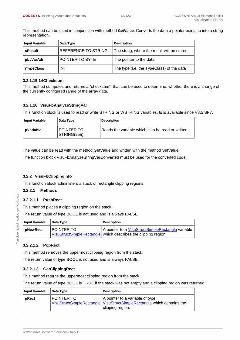
CODESYS Inspiring Automation Solutions 66/123 CODESYS Visual Element Toolkit Visualization Library
© 3S-Smart Software Solutions GmbH
Tem
plat
e: t
empl
_tec
doc_
en_V
1.0.
docx
This method can be used in conjunction with method GetValue. Converts the data a pointer points to into a string representation.
Input Variable Data Type Description
sResult REFERENCE TO STRING The string, where the result will be stored.
pbyVarAdr POINTER TO BYTE The pointer to the data
iTypeClass INT The type (i.e. the TypeClass) of the data
3.2.1.15.14 Checksum This method computes and returns a “checksum”, that can be used to determine, whether there is a change of the currently configured range of the array data.
3.2.1.16 VisuFbAnalyzeStringVar
This function block is used to read or write STRING or WSTRING variables. Is is available since V3.5 SP7.
Input Variable Data Type Description
pVariable POINTER TO STRING(255)
Reads the variable which is to be read or written.
The value can be read with the method GetValue and written with the method SetValue.
The function block VisuFbAnalyzeStringVarConverted must be used for the converted code.
3.2.2 VisuFbClippingInfo
This function block administers a stack of rectangle clipping regions.
3.2.2.1 Methods
3.2.2.1.1 PushRect
This method places a clipping region on the stack.
The return value of type BOOL is not used and is always FALSE.
Input Variable Data Type Description
pNewRect POINTER TO VisuStructSimpleRectangle
A pointer to a VisuStructSimpleRectangle variable which describes the clipping region.
3.2.2.1.2 PopRect
This method removes the uppermost clipping region from the stack.
The return value of type BOOL is not used and is always FALSE.
3.2.2.1.3 GetClippingRect
This method returns the uppermost clipping region from the stack.
The return value of type BOOL is TRUE if the stack was not empty and a clipping region was returned.
Input Variable Data Type Description
pRect POINTER TO VisuStructSimpleRectangle
A pointer to a variable of type VisuStructSimpleRectangle which contains the clipping region.
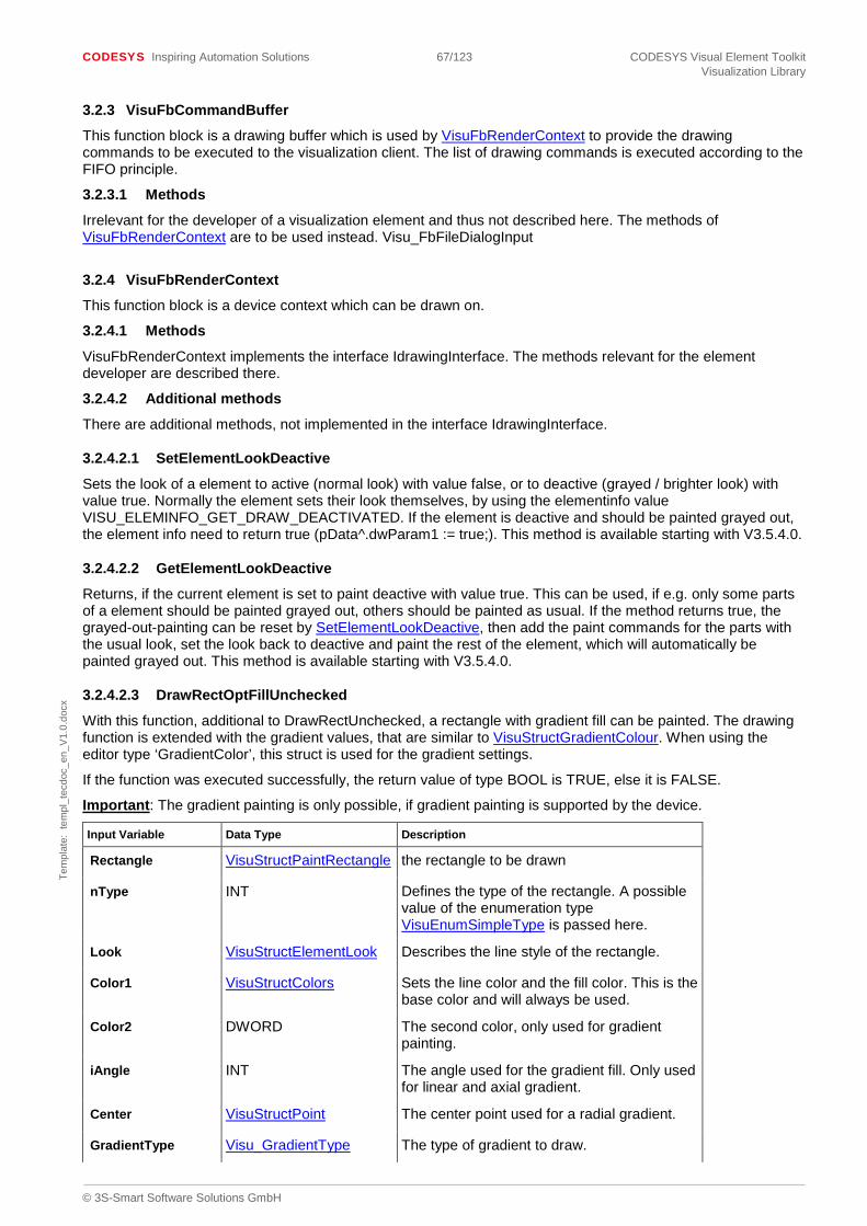
CODESYS Inspiring Automation Solutions 67/123 CODESYS Visual Element Toolkit Visualization Library
© 3S-Smart Software Solutions GmbH
Tem
plat
e: t
empl
_tec
doc_
en_V
1.0.
docx
3.2.3 VisuFbCommandBuffer
This function block is a drawing buffer which is used by VisuFbRenderContext to provide the drawing commands to be executed to the visualization client. The list of drawing commands is executed according to the FIFO principle.
3.2.3.1 Methods
Irrelevant for the developer of a visualization element and thus not described here. The methods of VisuFbRenderContext are to be used instead. Visu_FbFileDialogInput
3.2.4 VisuFbRenderContext
This function block is a device context which can be drawn on.
3.2.4.1 Methods
VisuFbRenderContext implements the interface IdrawingInterface. The methods relevant for the element developer are described there.
3.2.4.2 Additional methods
There are additional methods, not implemented in the interface IdrawingInterface.
3.2.4.2.1 SetElementLookDeactive
Sets the look of a element to active (normal look) with value false, or to deactive (grayed / brighter look) with value true. Normally the element sets their look themselves, by using the elementinfo value VISU_ELEMINFO_GET_DRAW_DEACTIVATED. If the element is deactive and should be painted grayed out, the element info need to return true (pData^.dwParam1 := true;). This method is available starting with V3.5.4.0.
3.2.4.2.2 GetElementLookDeactive
Returns, if the current element is set to paint deactive with value true. This can be used, if e.g. only some parts of a element should be painted grayed out, others should be painted as usual. If the method returns true, the grayed-out-painting can be reset by SetElementLookDeactive, then add the paint commands for the parts with the usual look, set the look back to deactive and paint the rest of the element, which will automatically be painted grayed out. This method is available starting with V3.5.4.0.
3.2.4.2.3 DrawRectOptFillUnchecked
With this function, additional to DrawRectUnchecked, a rectangle with gradient fill can be painted. The drawing function is extended with the gradient values, that are similar to VisuStructGradientColour. When using the editor type ‘GradientColor’, this struct is used for the gradient settings.
If the function was executed successfully, the return value of type BOOL is TRUE, else it is FALSE.
Important: The gradient painting is only possible, if gradient painting is supported by the device.
Input Variable Data Type Description
Rectangle VisuStructPaintRectangle the rectangle to be drawn
nType INT Defines the type of the rectangle. A possible value of the enumeration type VisuEnumSimpleType is passed here.
Look VisuStructElementLook Describes the line style of the rectangle.
Color1 VisuStructColors Sets the line color and the fill color. This is the base color and will always be used.
Color2 DWORD The second color, only used for gradient painting.
iAngle INT The angle used for the gradient fill. Only used for linear and axial gradient.
Center VisuStructPoint The center point used for a radial gradient.
GradientType Visu_GradientType The type of gradient to draw.

CODESYS Inspiring Automation Solutions 68/123 CODESYS Visual Element Toolkit Visualization Library
© 3S-Smart Software Solutions GmbH
Tem
plat
e: t
empl
_tec
doc_
en_V
1.0.
docx
Input Variable Data Type Description
bDrawUnchecked BOOL TRUE if the drawing operation is to be executed in any case and FALSE if the drawing operation is to be executed only if there is a coverage of the screen area to be refreshed.
bDrawGradientFill BOOL TRUE if the fill is painted as gradient and FALSE if normal fill has to be used.
bUseTwoColors INT 0: a gradient with two different colors (normal case) 1: a gradient with one color. In this case the second color is of a brighter or darker shade of the base color.
iBrightness INT Only needed for a gradient with one color. The brightness of the second color, calculated from the base color. 0: the darkest color 100: the brightest color.
Color_brightness DWORD Only needed for a gradient with one color. This is the color, that is calculated with the base color and the iBrightness.
pClientdata POINTER TO VisuStructClientData
Pointer to a VisuStructClientData variable which contains information on the client on which the drawing operation is executed.
pPaintBuffer POINTER TO VisuFbCommandBuffer
Pointer to a VisuFbCommandBuffer variable which contains the paint buffer.
3.2.4.2.4 DrawRectOptFillUncheckedF
Draws a rectangle of type VisuStructPaintRectangleF. The input variables are similar then in DrawRectOptFillUnchecked, except the data type of the rectangle. For more information see chapter Absolute animation with coordinates of type REAL.
3.2.4.2.5 DrawPolygonOptFillUnchecked
With this function, additional to DrawPolygonUnchecked, a polygon with gradient fill can be painted. The drawing function is extended with the gradient values, that are similar to VisuStructGradientColour. When using the editor type ‘GradientColor’, this struct is used for the gradient settings.
If the function was executed successfully, the return value of type BOOL is TRUE, else it is FALSE.
Important: The gradient painting is only possible, if gradient painting is supported by the device.
Input Variable Data Type Description
Polygon VisuStructPolygon the polygon to be drawn
iType INT Describes the type of polygon. The enumeration type VisuEnumPolygonType contains possible values.
Look VisuStructElementLook Describes the linestyle of the frequency polygon.
Color1 VisuStructColors Sets the line color and the fill color. This is the base color and will always be used.
Color2 DWORD The second color, only used for gradient painting.
iAngle INT The angle used for the gradient fill. Only used for linear and axial gradient.

CODESYS Inspiring Automation Solutions 69/123 CODESYS Visual Element Toolkit Visualization Library
© 3S-Smart Software Solutions GmbH
Tem
plat
e: t
empl
_tec
doc_
en_V
1.0.
docx
Center VisuStructPoint The center point used for a radial gradient.
GradientType Visu_GradientType The type of gradient to draw.
bDrawGradientFill BOOL TRUE if the fill is painted as gradient and FALSE if normal fill has to be used.
bUseTwoColors INT 0: a gradient with two different colors (normal case) 1: a gradient with one color. In this case the second color is of a brighter or darker shade of the base color.
iBrightness INT Only needed for a gradient with one color. The brightness of the second color, calculated from the base color. 0: the darkest color 100: the brightest color.
Color_brightness DWORD Only needed for a gradient with one color. This is the color, that is calculated with the base color and the iBrightness.
bDrawUnchecked BOOL TRUE if the drawing operation is to be executed in any case and FALSE if the drawing operation is to be executed only if there is a coverage of the screen area to be refreshed.
bDrawUntransformed BOOL TRUE if a possible transformation is to be ignored when drawing and FALSE if the transformations are to be considered.
pClientdata POINTER TO VisuStructClientData
Pointer to a VisuStructClientData variable which contains information on the client on which the drawing operation is executed.
pPaintBuffer POINTER TO VisuFbCommandBuffer
Pointer to a VisuFbCommandBuffer variable which contains the paint buffer.
3.2.4.2.6 DrawPolygonOptFillUncheckedF
Draws a polygon of type VisuStructPolygonF. The input variables are similar then in DrawPolygonOptFillUnchecked, except the data type of the polygon. For more information see chapter Absolute animation with coordinates of type REAL
3.2.4.2.7 DrawPieOptFillUnchecked
With this function, additional to DrawPieUnchecked, a pie with gradient fill can be painted. The drawing function is extended with the gradient values, that are similar to VisuStructGradientColour. When using the editor type ‘GradientColor’, this struct is used for the gradient settings.
If the function was executed successfully, the return value of type BOOL is TRUE, else it is FALSE.
Important: The gradient painting is only possible, if gradient painting is supported by the device.
Input Variable Data Type Description
Rectangle VisuStructPaintRectangle
The rectangle, where the pie has to be painted.
startAngle INT Angle measured in degrees clockwise from the x-axis to the first side of the pie shape.
sweepAngle INT Angle measured in degrees clockwise from the startAngle parameter to the second side of the pie shape.
iType VisuEnumPieType Defines the type of the pie.

CODESYS Inspiring Automation Solutions 70/123 CODESYS Visual Element Toolkit Visualization Library
© 3S-Smart Software Solutions GmbH
Tem
plat
e: t
empl
_tec
doc_
en_V
1.0.
docx
Input Variable Data Type Description
Look VisuStructElementLook Describes the line style of the pie.
Color1 VisuStructColors Sets the line color and the fill color. This is the base color and will always be used.
Color2 DWORD The second color, only used for gradient painting.
iAngle INT The angle used for the gradient fill. Only used for linear and axial gradient.
Center VisuStructPoint The center point used for a radial gradient.
GradientType Visu_GradientType The type of gradient to draw.
bUseTwoColors INT 0: a gradient with two different colors (normal case) 1: a gradient with one color. In this case the second color is of a brighter or darker shade of the base color.
iBrightness INT Only needed for a gradient with one color. The brightness of the second color, calculated from the base color. 0: the darkest color 100: the brightest color.
Color_brightness DWORD Only needed for a gradient with one color. This is the color, that is calculated with the base color and the iBrightness.
bDrawGradientFill BOOL TRUE if the fill is painted as gradient and FALSE if normal fill has to be used.
bDrawUnchecked BOOL TRUE if the drawing operation is to be executed in any case and FALSE if the drawing operation is to be executed only if there is a coverage of the screen area to be refreshed.
bDrawUntransformed BOOL TRUE if a possible transformation is to be ignored when drawing and FALSE if the transformations are to be considered.
pClientdata POINTER TO VisuStructClientData
Pointer to a VisuStructClientData variable which contains information on the client on which the drawing operation is executed.
pPaintBuffer POINTER TO VisuFbCommandBuffer
Pointer to a VisuFbCommandBuffer variable which contains the paint buffer.
3.2.4.2.8 DrawGradientButtonOnClient
This method draws a gradient button. The drawing function is extended with the gradient values, that are similar to VisuStructGradientColour. When using the editor type ‘GradientColor’, this struct is used for the gradient settings.
If the function was executed successfully, the return value of type BOOL is TRUE, else it is FALSE.
Important: The gradient painting is only possible, if gradient painting is supported by the device.
Input Variable Data Type Description
bHighButton BOOL If this variable is TRUE the variable iColorCount is evaluated, if it is FALSE it is not.

CODESYS Inspiring Automation Solutions 71/123 CODESYS Visual Element Toolkit Visualization Library
© 3S-Smart Software Solutions GmbH
Tem
plat
e: t
empl
_tec
doc_
en_V
1.0.
docx
Input Variable Data Type Description
bPressed BOOL TRUE if the button is to be displayed as pressed, else FALSE.
iColorCount INT This variable is only evaluated if bHighButton is TRUE. This variable defines the pixel width of the light lines and shadow lines of the button.
Rectangle VisuStructPaintRectangle
The VisuStructPaintRectangle variable describes the position of the button.
Color1 VisuStructColors Sets the line color and the fill color. This is the base color.
Color2 DWORD The second color.
iAngle INT The angle used for the gradient fill. Only used for linear and axial gradient.
Center VisuStructPoint The center point used for a radial gradient.
GradientType Visu_GradientType The type of gradient to draw.
iUseTwoColors INT 0: a gradient with two different colors (normal case) 1: a gradient with one color. In this case the second color is of a brighter or darker shade of the base color.
iBrightness INT Only needed for a gradient with one color. The brightness of the second color, calculated from the base color. 0: the darkest color 100: the brightest color.
Color_brightness DWORD Only needed for a gradient with one color. This is the color, that is calculated with the base color and the iBrightness.
bDrawUnchecked BOOL TRUE if the drawing operation is to be executed in any case and FALSE if the drawing operation is to be executed only if there is a coverage of the screen area to be refreshed.
pClientdata POINTER TO VisuStructClientData
Pointer to a VisuStructClientData variable which contains information on the client on which the drawing operation is executed.
pPaintBuffer POINTER TO VisuFbCommandBuffer
Pointer to a VisuFbCommandBuffer variable which contains the paint buffer.
3.2.4.2.9 MeasureString
Used, to start measuring of a string. Typically, this method is called from the method Paint of the visual element functionblock. Every call of this method starts a new measuring and avoids the painting of the element. Therefore, this method should only be called when needed. E.g. only as long as the result is not yet available. The returnvalue is the index of the result. This index is needed for getting the result by using VisuFctGetMeasureStringResult.
Example:
IF (dwFlags AND VisuEnumPaintFlags.InitMeasureString) <> 0 THEN IF TextSize.iWidth <= 0 THEN

CODESYS Inspiring Automation Solutions 72/123 CODESYS Visual Element Toolkit Visualization Library
© 3S-Smart Software Solutions GmbH
Tem
plat
e: t
empl
_tec
doc_
en_V
1.0.
docx
m_iMeasureStringResult:= m_pCurrentClientData^.GlobalData.DrawingContext.MeasureString( Font := m_DefaultFont, pstText := EffectiveTexts.pstText, bWstring := g_bWstring, pPaintBuffer := ADR(m_pCurrentClientData^.PaintBuffer) ); END_IF END_IF Input Variable Data Type Description
Font VisuStructFont The font which should be used for measuring.
pstText POINTER TO Byte Pointer to the text, that should be measured. The text has to be of type STRING or WSTRING.
bWstring BOOL True, if the string is of type WSTRING. Else false.
pPaintBuffer POINTER TO VisuFbCommandBuffer
Pointer to a VisuFbCommandBuffer variable which contains the paint buffer.
Starting with V3.5 SP9 an additional string measuring functionality was introduced, that measures a string including all the beginning substrings of the string. Example: If the string ‘Hello’ has to be measured, the following strings will be measured: ‘H’, ‘He’, ‘Hel’, ‘Hell’ and ‘Hello’. The following methods and functions have to be used:
• MeasureString2: New measuring method, similar to MeasureString. In contrast to method MeasureString the new method MeasureString2 can be used during a “normal” Update-Paint cycle (i.e. not in case of VisuEnumPaintFlags.InitMeasureString), e.g. if the string was changed dynamically through Update. If the results of a previous MeasureString2 call are not yet processed the variable VisuStructClientData.GlobalData.eMeasureString2State has the value VisuEnumMeasureString2State.WAITING_FOR_RESULTS. This indicates, that the measuring call has to be retried in the next Update-Paint cycle.
• VisuFctGetMeasureString2Result: New function similar to VisuFctGetMeasureStringResult.
3.2.4.2.10 ClipRectangle
With this method, a rectangle, which should be used for clipping, can be added. The returnvalue is not used.
Normaly, the clipping rectangle is added before painting of parts, that should be clipped. And removed again, after painting, see UnclipRectangle. An example of the usage of clipping is added to the example library V3.5.11.0 in folder AdditionalExamples – Clipping.
Input Variable Data Type Description
rectPosition VisuStructSimpleRectangle The rectangle to add as clip rectangle
pPaintBuffer POINTER TO VisuFbCommandBuffer
Pointer to a VisuFbCommandBuffer variable which contains the paint buffer.
3.2.4.2.11 PushClipRect
This methods adds the clipping rectangle to a local stack (of type VisuFbClippingInfo) in the render context. This stack is used for information.
Input Variable Data Type Description
pRect POINTER TO VisuStructSimpleRectangle
The clipping rectangle to add to the information stack
With “GetCurrentClipRect” can be checked, if a clipping rectangle is set, and the last added will be returned.

CODESYS Inspiring Automation Solutions 73/123 CODESYS Visual Element Toolkit Visualization Library
© 3S-Smart Software Solutions GmbH
Tem
plat
e: t
empl
_tec
doc_
en_V
1.0.
docx
3.2.4.2.12 UnclipRectangle
The rectangle, set in ClipRectangle will be reset with this method.
Input Variable Data Type Description
rectPosition VisuStructSimpleRectangle The rectangle to add as clip rectangle
pPaintBuffer POINTER TO VisuFbCommandBuffer
Pointer to a VisuFbCommandBuffer variable which contains the paint buffer.
3.2.4.2.13 PopClipRect
The rectangle, set with PushClipRect, will be reset with this method.
3.3 Types
3.3.1 Visu_TypeString
This type is always used when wanting to save strings which have to be internationalized. This type may contain STRING and WSTRING.
3.3.2 VisuFbInputBase2
This type is the function block which handles input. Input in the method IvisualElement.HandleInput is delegated to this function block.
3.3.3 VisuTypeChecksum
Visu_TypeChecksum is the return value of the checksum method which every visualization element should have in order to be able to determine which parts of the visualization element have to be redrawn. This type is equivalent to UDINT.
3.4 Structures
3.4.1 Visu_StructButtonColors
This structure describes the color used to draw a button.
The components:
Variable Data Type Description
dwBaseColor DWORD Base color of the button.
dwLightColor DWORD Color of the light edges of the button.
dwDarkColor DWORD Shadow color of the dark edges of the button.
3.4.2 VisuStructClientData
This structure contains information on the client currently executing the visualization. It is passed to the visualization element using the method IvisualElement.SetClientData. The following list only describes those components which are relevant for the element developer.
The components:
Variable Data Type Description
GlobalData VisuStructGlobalClientData Gives access to the device context drawn on.

CODESYS Inspiring Automation Solutions 74/123 CODESYS Visual Element Toolkit Visualization Library
© 3S-Smart Software Solutions GmbH
Tem
plat
e: t
empl
_tec
doc_
en_V
1.0.
docx
AdditionalElementsData VisuStructAdditionalElementClientData
Offers access to additional memory for client-dependent data
3.4.3 VisuStructColors
This structure describes the colors of a visualization element.
The components:
Variable Data Type Description
dwFrameColor DWORD frame color The default value is black (16#FF000000).
dwFillColor DWORD Background color: The default value is white (16#FFFFFFFF).
Starting with CODESYS V3.5.6.0 also the alpha-value of the color is considered, when it is supported by the device and is activated in the project. (16#AARRGGBB). A alpha-value of 255 means fully-opaque, 0 means fully-transparent.
3.4.4 VisuStructDynamicTexts
This structure is used in the configuration of a visualization element for the configuration of dynamic text lists. A pointer to such a variable is passed to the method IvisuTextTranslator.GetLanguageText in order to be able to use dynamic text lists when internationalizing texts.
The components:
Variable Data Type Description
stTextList STRING Contains the name of the text list.
stTextIndex STRING Contains the key for the text.
stTooltipIndex STRING Contains the key for the tooltip text.
wValidDynamicText WORD Irrelevant for element developers. Occupied by the code generation.
3.4.5 VisuStructElementColors
This structure contains the colors of a visualization element.
The components:
Variable Data Type Description
NormalColors VisuStructColors Color in normal state
AlarmColors VisuStructColors Color in alarm state
3.4.6 Visu_StructElementInfo
This structure contains the information passed on to the method IvisualElement.ElementInfo.
The components:

CODESYS Inspiring Automation Solutions 75/123 CODESYS Visual Element Toolkit Visualization Library
© 3S-Smart Software Solutions GmbH
Tem
plat
e: t
empl
_tec
doc_
en_V
1.0.
docx
Variable Data Type Description
iSize INT The size of this structure. Reserved for future extensions. This component may not be written on! Not relevant for the end user.
iVersion INT The version number of the structure. Reserved for future extensions. This component may not be written on! Not relevant for the end user.
iRequestedInfo INT The type of the desired information. One of the VISU_ELEMINFO_* constants.
bWriteAccess BOOL If this variable is TRUE something is to be written into this structure.
bRecursive BOOL If this variable is TRUE the call in the visualization element is to be passed on to embedded visualization elements too.
dwParam1 __XWORD Parameter, dependent on passed iRequestedInfo parameter Is used as INOUT parameter. Compatibility Note: The type of this parameter was changed from DWORD to __XWORD starting with the version 3.5.5 for being able to support 64-Bit systems.
dwParam2 __XWORD Parameter, dependent on passed iRequestedInfo parameter Is used as INOUT parameter. Compatibility Note: The type of this parameter was changed from DWORD to __XWORD starting with the version 3.5.5 for being able to support 64-Bit systems.

CODESYS Inspiring Automation Solutions 76/123 CODESYS Visual Element Toolkit Visualization Library
© 3S-Smart Software Solutions GmbH
Tem
plat
e: t
empl
_tec
doc_
en_V
1.0.
docx
3.4.7 VisuStructElementLook
This structure describes the style for drawing an element, i.e. for drawing lines and filling areas.
The components:
Variable Data Type Description
iLineWidth INT line width in pixel The default value is 1.
dwFillFlags DWORD Determines the area filling. The enumeration type VisuEnumBrushStyle contains possible values.
dwFrameFlags DWORD Determines how the lines of the element frame are to be drawn. The enumeration type VisuEnumPenStyle contains possible values.
3.4.8 VisuStructElementState
This structure encapsulates the information on the current state of the element for the element.
The components:
Variable Data Type Description
bInvisible BOOL Element is invisible.
bInputDeactivated BOOL The element input is deactivated.
3.4.9 VisuStructElementTexts
This structure encapsulates the element text and the tooltip text for the element. This structure is only used for internal use, e.g. as return value.
The components:
Variable Data Type Description
pstText Visu_TypeString contains the text
pstToolTip Visu_TypeString contains the tooltip text May be NULL.
3.4.10 VisuStructStaticTexts
This structure includes the texts of an element. Use this structure for the Var_Input of the element functionblock.
The components:
Variable Data Type Description
pstText Visu_TypeString contains the text
pstToolTip Visu_TypeString contains the tooltip text May be NULL.
3.4.11 VisuStructEvent
This structure describes an event. The following table only describes the components which are relevant for the element developer.
The components:
Variable Data Type Description
EventTag DWORD Identifies the event. Possible values are the VISU_ET*-Konstanten from the library VisuElemBase.

CODESYS Inspiring Automation Solutions 77/123 CODESYS Visual Element Toolkit Visualization Library
© 3S-Smart Software Solutions GmbH
Tem
plat
e: t
empl
_tec
doc_
en_V
1.0.
docx
dwParam1 DWORD Contains additional information on the event such as the current mouse position.
dwParam2 DWORD Contains additional information on the event.
3.4.12 VisuStructFont
This structure describes a font.
The components:
Variable Data Type Description
Name STRING The name of the font. The default is “Arial”.
Height INT Point size of the font. The default value is 12.
Flags DWORD May contain a bit-OR-combined value of font flags such as bold, italic, underline. Following values are supported:
Italic: 16#00000001,
Bold: 16#00000002,
Underline: 16#00000004,
StrikeOut: 16#00000008,
NoLanguageDependency: 16#00000100 (Visu_Constant: FONT_FLAG_NO_LANGUAGE_DEPENDENCY)
CharSet DWORD Contains the character set. Normally, irrelevant for element developers.
Color DWORD color to be used The default value is black.
3.4.13 VisuStructFrameElementLook
This structure describes the frame properties of a visualization element.
The components:
Variable Data Type Description
iLineWidth INT Line width in pixel. The default value is one.
dwFrameFlags DWORD Determines how the lines of the element frame are to be drawn. The enumeration type VisuEnumPenStyle contains possible values.
3.4.14 VisuStructGlobalClientData
This structure contains global data of the current client. The following table only describes the components which are relevant for the element developer.
The components:
Variable Data Type Description
DrawingContext VisuFbRenderContext device context to be drawn on
CurrentUpdateRects VisuFbSimpleRectangleList Contains a list with all update rectangles which have to be redrawn.

CODESYS Inspiring Automation Solutions 78/123 CODESYS Visual Element Toolkit Visualization Library
© 3S-Smart Software Solutions GmbH
Tem
plat
e: t
empl
_tec
doc_
en_V
1.0.
docx
3.4.15 VisuStructMoveAbsoluteData
This structure contains the information on a dynamic position change of the visualization element. This structure should be used if a visualization element is to be moved, rotated or scaled dynamically.
The components:
Variable Data Type Description
MoveBy VisuStructPoint
The element is moved by the offset X/Y which can be found in this point.
RotateBy INT The element is rotated at this angle around the center of the element. It does not rotate around its own axis. (just like gondolas on a ferris wheel).
The angle is interpreted in degrees.
ScaleBy INT The element is scaled from its center. The scaling factor 1000 is equivalent to 1.0 no scaling. 100 is equivalent to 0.1 the element is scaled down.
RotateInteriorBy INT The element is rotated at this angle around the center of the element. And the element itself is also rotated.
The angle is interpreted in degrees.
Please notice: this type of rotation is usable starting with V3.5.4.0. Also the according setting in the device description is needed to activate this rotation. (TargetConstraint: InteriorRotationElements)
3.4.16 VisuStructMoveAbsoluteDataF
This structure contains the information on a dynamic position change of the visualization element. This structure should be used if a visualization element is to be moved, rotated or scaled dynamically. The structure is similar to VisuStructMoveAbsoluteData, but using variables of type REAL, instead of INT. It is used within VisuFbMoveAbsoluteF.
The components:
Variable Data Type Description
MoveBy VisuStructPointF
The element is moved by the offset X/Y which can be found in this point.
rRotateBy REAL The element is rotated at this angle around the center of the element. It does not rotate around its own axis. (just like gondolas on a ferris wheel).
The angle is interpreted in degrees.
rScaleBy REAL The element is scaled from its center. The scaling factor 1000.0 is equivalent to 1.0 no scaling. 100.0 is equivalent to 0.1 the element is scaled down.
rRotateInteriorBy REAL The element is rotated at this angle around the center of the element. And the element itself is also rotated.
The angle is interpreted in degrees.

CODESYS Inspiring Automation Solutions 79/123 CODESYS Visual Element Toolkit Visualization Library
© 3S-Smart Software Solutions GmbH
Tem
plat
e: t
empl
_tec
doc_
en_V
1.0.
docx
3.4.17 VisuStructPaintRectangle
This structure describes a rectangle.
The components:
Variable Data Type Description
m_Points ARRAY [0..3] OF VisuStructPoint
Array of four points which describe the corners of the rectangle. Beginning with the top left corner the points are counted clockwise.
3.4.18 VisuStructPaintRectangleF
This structure describes a rectangle with points of type VisuStructPointF.
The components:
Variable Data Type Description
m_Points ARRAY [0..3] OF VisuStructPointF
Array of four points which describe the corners of the rectangle. Beginning with the top left corner the points are counted clockwise.
3.4.19 VisuStructPoint
This structure describes a point.
The components:
Variable Data Type Description
iX INT the X coordinate of the point
iY INT the Y coordinate of the point
3.4.20 VisuStructPointF
This structure describes a point with coordinates of type REAL.
The components:
Variable Data Type Description
rX REAL the X coordinate of the point
rY REAL the Y coordinate of the point
3.4.21 VisuStructPolygon
This structure describes a frequency polygon.
The components:
Variable Data Type Description
pPoints POINTER TO ARRAY [0..255] OF VisuStructPoint
the points which describe the frequency polygon A pointer to an array with a different size can also be saved in this structure variable. Should this be the case, the correct number of array elements must be passed in iPointCount.
iPointCount INT The number of points in the array pPoints.
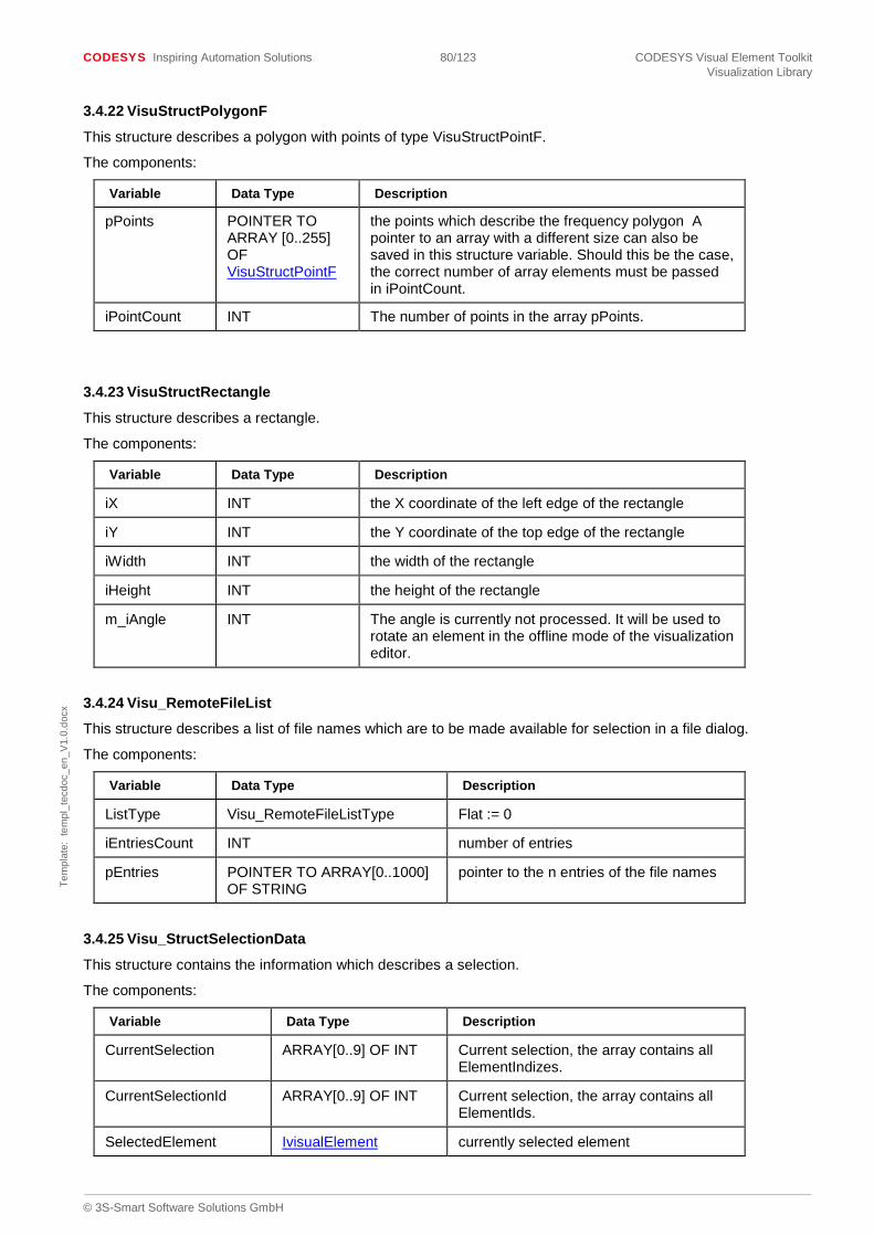
CODESYS Inspiring Automation Solutions 80/123 CODESYS Visual Element Toolkit Visualization Library
© 3S-Smart Software Solutions GmbH
Tem
plat
e: t
empl
_tec
doc_
en_V
1.0.
docx
3.4.22 VisuStructPolygonF
This structure describes a polygon with points of type VisuStructPointF.
The components:
Variable Data Type Description
pPoints POINTER TO ARRAY [0..255] OF VisuStructPointF
the points which describe the frequency polygon A pointer to an array with a different size can also be saved in this structure variable. Should this be the case, the correct number of array elements must be passed in iPointCount.
iPointCount INT The number of points in the array pPoints.
3.4.23 VisuStructRectangle
This structure describes a rectangle.
The components:
Variable Data Type Description
iX INT the X coordinate of the left edge of the rectangle
iY INT the Y coordinate of the top edge of the rectangle
iWidth INT the width of the rectangle
iHeight INT the height of the rectangle
m_iAngle INT The angle is currently not processed. It will be used to rotate an element in the offline mode of the visualization editor.
3.4.24 Visu_RemoteFileList
This structure describes a list of file names which are to be made available for selection in a file dialog.
The components:
Variable Data Type Description
ListType Visu_RemoteFileListType Flat := 0
iEntriesCount INT number of entries
pEntries POINTER TO ARRAY[0..1000] OF STRING
pointer to the n entries of the file names
3.4.25 Visu_StructSelectionData
This structure contains the information which describes a selection.
The components:
Variable Data Type Description
CurrentSelection ARRAY[0..9] OF INT Current selection, the array contains all ElementIndizes.
CurrentSelectionId ARRAY[0..9] OF INT Current selection, the array contains all ElementIds.
SelectedElement IvisualElement currently selected element

CODESYS Inspiring Automation Solutions 81/123 CODESYS Visual Element Toolkit Visualization Library
© 3S-Smart Software Solutions GmbH
Tem
plat
e: t
empl
_tec
doc_
en_V
1.0.
docx
Variable Data Type Description
SelectedVisualization Ivisualisation currently selected visualization
PrevSelectedRect VisuStructSimpleRectangle
previously selected rectangle
SelectedRect VisuStructSimpleRectangle
selected rectangle
bSelectionChanged BOOL State if the selection has changed.
nElementPosition INT position in the position array
3.4.26 VisuStructSimpleRectangle
This structure describes a rectangle.
The components:
Variable Data Type Description
ptTopLeft VisuStructPoint The top left corner of the rectangle.
ptBottomRight VisuStructPoint The bottom right corner of the rectangle.
3.4.27 VisuStructTextProperties
This structure describes properties of a text.
The components:
Variable Data Type Description
HorizontalAlignment VisuEnumHorizontalAlignment
horizontal alignment of the text The default value is VisuEnumHorizontalAlignment.HCENTER
VerticalAlignment VisuEnumVerticalAlignment
vertical alignment of the text The default value is VisuEnumVerticalAlignment.VCENTER
TextFlag VisuEnumTextFlag Other possible text flags. The default is VisuEnumTextFlag.NONE
Font VisuStructFont Font of the text.
3.4.28 VisuStructGradientColour
This structure describes the settings of a gradient colour fill.
The components:
Variable Data Type Description
m_Color_1 DWORD Color 1, default is black
m_Color_2 DWORD Color 2, default is white
m_iAngle INT Angle of linear and axial gradient
m_pCenterX INT X-coordinate of radial gradient center
m_pCenterY INT Y-coordinate of radial gradient center

CODESYS Inspiring Automation Solutions 82/123 CODESYS Visual Element Toolkit Visualization Library
© 3S-Smart Software Solutions GmbH
Tem
plat
e: t
empl
_tec
doc_
en_V
1.0.
docx
m_GradientType INT Type of gradient: Possible settings are: 0: linear, 1: radial, 2: axial
m_iUseTwoColors INT Defines, if the gradient is drawn with two different colors (Color1 and Color2) or with one color and a brighter/darker shade (Color1 and ColorBright). Possible settings: 0: two different colors, 1: one color + shade
m_iBrightness INT Brightness of shade color: 0: darkest shade, 1: brightest shade
m_Color_Bright DWORD Color Bright: Color-Value of shade color.
3.5 Enumeration Types
3.5.1 VisuEnumCursor
This enumeration type describes the shape of the mouse pointer. The values (CS_*) have the same meaning as the Windows API constants of the same name.
3.5.2 VisuEnumBrushStyle
This enumeration type described the way areas are filled.
The values:
Value Description
BS_SOLID This color is used to fill the areas.
BS_HOLLOW Area filling is invisible.
3.5.3 VisuEnumHorizontalAlignment
This enumeration type describes the possible values for horizontal text alignment.
The values:
Value Description Enumvalue
LEFT left-aligned 16#00
HCENTER centered 16#01
RIGHT right-aligned 16#02
3.5.4 VisuEnumVerticalAlignment
This enumeration type describes the possible values for vertical text alignment.
The values:
Value Description Enumvalue
TOP align to top edge 16#00
VCENTER centered 16#04
BOTTOM align to bottom edge 16#08
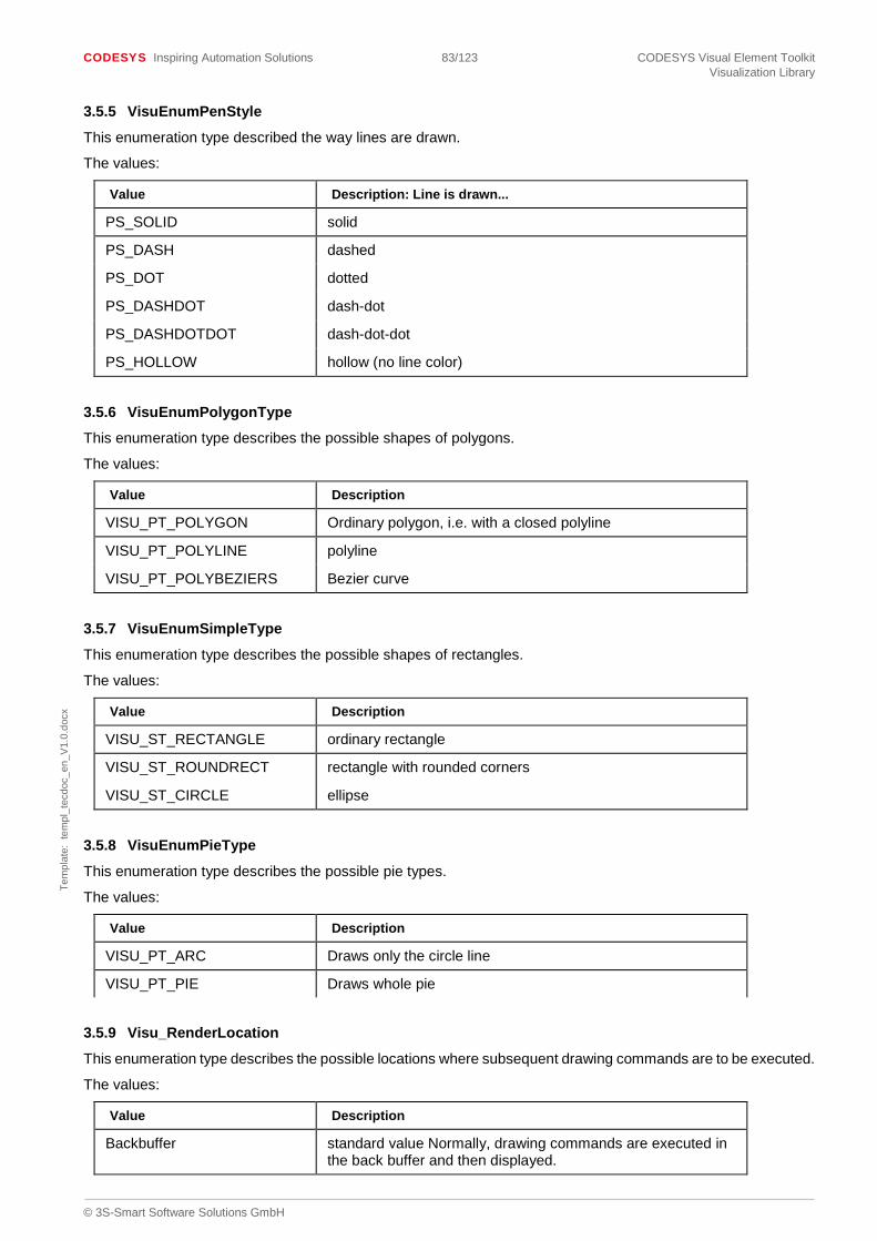
CODESYS Inspiring Automation Solutions 83/123 CODESYS Visual Element Toolkit Visualization Library
© 3S-Smart Software Solutions GmbH
Tem
plat
e: t
empl
_tec
doc_
en_V
1.0.
docx
3.5.5 VisuEnumPenStyle
This enumeration type described the way lines are drawn.
The values:
Value Description: Line is drawn...
PS_SOLID solid
PS_DASH dashed
PS_DOT dotted
PS_DASHDOT dash-dot
PS_DASHDOTDOT dash-dot-dot
PS_HOLLOW hollow (no line color)
3.5.6 VisuEnumPolygonType
This enumeration type describes the possible shapes of polygons.
The values:
Value Description
VISU_PT_POLYGON Ordinary polygon, i.e. with a closed polyline
VISU_PT_POLYLINE polyline
VISU_PT_POLYBEZIERS Bezier curve
3.5.7 VisuEnumSimpleType
This enumeration type describes the possible shapes of rectangles.
The values:
Value Description
VISU_ST_RECTANGLE ordinary rectangle
VISU_ST_ROUNDRECT rectangle with rounded corners
VISU_ST_CIRCLE ellipse
3.5.8 VisuEnumPieType
This enumeration type describes the possible pie types.
The values:
Value Description
VISU_PT_ARC Draws only the circle line
VISU_PT_PIE Draws whole pie
3.5.9 Visu_RenderLocation
This enumeration type describes the possible locations where subsequent drawing commands are to be executed.
The values:
Value Description
Backbuffer standard value Normally, drawing commands are executed in the back buffer and then displayed.
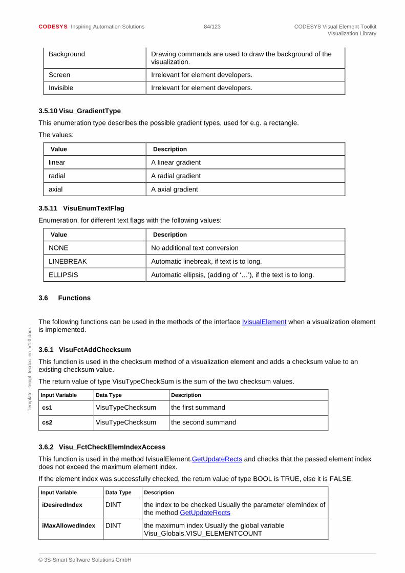
CODESYS Inspiring Automation Solutions 84/123 CODESYS Visual Element Toolkit Visualization Library
© 3S-Smart Software Solutions GmbH
Tem
plat
e: t
empl
_tec
doc_
en_V
1.0.
docx
Background Drawing commands are used to draw the background of the visualization.
Screen Irrelevant for element developers.
Invisible Irrelevant for element developers.
3.5.10 Visu_GradientType
This enumeration type describes the possible gradient types, used for e.g. a rectangle.
The values:
Value Description
linear A linear gradient
radial A radial gradient
axial A axial gradient
3.5.11 VisuEnumTextFlag
Enumeration, for different text flags with the following values:
Value Description
NONE No additional text conversion
LINEBREAK Automatic linebreak, if text is to long.
ELLIPSIS Automatic ellipsis, (adding of ‘…’), if the text is to long.
3.6 Functions
The following functions can be used in the methods of the interface IvisualElement when a visualization element is implemented.
3.6.1 VisuFctAddChecksum
This function is used in the checksum method of a visualization element and adds a checksum value to an existing checksum value.
The return value of type VisuTypeCheckSum is the sum of the two checksum values.
Input Variable Data Type Description
cs1 VisuTypeChecksum the first summand
cs2 VisuTypeChecksum the second summand
3.6.2 Visu_FctCheckElemIndexAccess
This function is used in the method IvisualElement.GetUpdateRects and checks that the passed element index does not exceed the maximum element index.
If the element index was successfully checked, the return value of type BOOL is TRUE, else it is FALSE.
Input Variable Data Type Description
iDesiredIndex DINT the index to be checked Usually the parameter elemIndex of the method GetUpdateRects
iMaxAllowedIndex DINT the maximum index Usually the global variable Visu_Globals.VISU_ELEMENTCOUNT
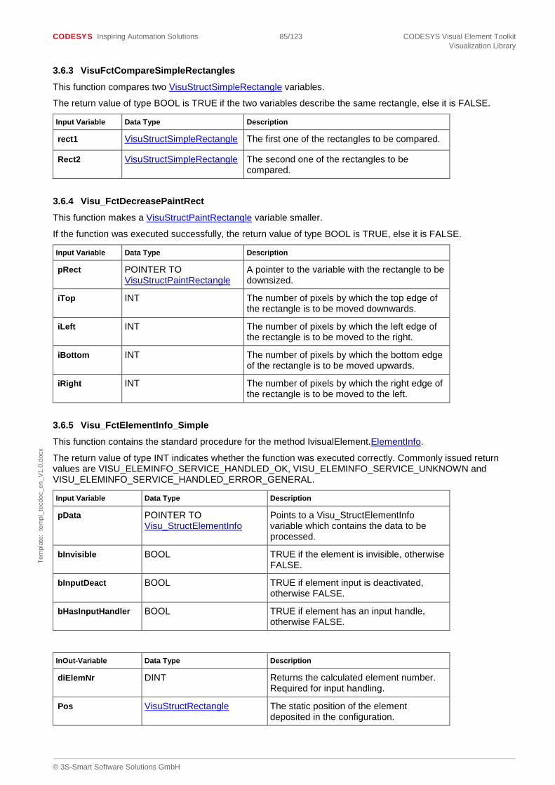
CODESYS Inspiring Automation Solutions 85/123 CODESYS Visual Element Toolkit Visualization Library
© 3S-Smart Software Solutions GmbH
Tem
plat
e: t
empl
_tec
doc_
en_V
1.0.
docx
3.6.3 VisuFctCompareSimpleRectangles
This function compares two VisuStructSimpleRectangle variables.
The return value of type BOOL is TRUE if the two variables describe the same rectangle, else it is FALSE.
Input Variable Data Type Description
rect1 VisuStructSimpleRectangle The first one of the rectangles to be compared.
Rect2 VisuStructSimpleRectangle The second one of the rectangles to be compared.
3.6.4 Visu_FctDecreasePaintRect
This function makes a VisuStructPaintRectangle variable smaller.
If the function was executed successfully, the return value of type BOOL is TRUE, else it is FALSE.
Input Variable Data Type Description
pRect POINTER TO VisuStructPaintRectangle
A pointer to the variable with the rectangle to be downsized.
iTop INT The number of pixels by which the top edge of the rectangle is to be moved downwards.
iLeft INT The number of pixels by which the left edge of the rectangle is to be moved to the right.
iBottom INT The number of pixels by which the bottom edge of the rectangle is to be moved upwards.
iRight INT The number of pixels by which the right edge of the rectangle is to be moved to the left.
3.6.5 Visu_FctElementInfo_Simple
This function contains the standard procedure for the method IvisualElement.ElementInfo.
The return value of type INT indicates whether the function was executed correctly. Commonly issued return values are VISU_ELEMINFO_SERVICE_HANDLED_OK, VISU_ELEMINFO_SERVICE_UNKNOWN and VISU_ELEMINFO_SERVICE_HANDLED_ERROR_GENERAL.
Input Variable Data Type Description
pData POINTER TO Visu_StructElementInfo
Points to a Visu_StructElementInfo variable which contains the data to be processed.
bInvisible BOOL TRUE if the element is invisible, otherwise FALSE.
bInputDeact BOOL TRUE if element input is deactivated, otherwise FALSE.
bHasInputHandler BOOL TRUE if element has an input handle, otherwise FALSE.
InOut-Variable Data Type Description
diElemNr DINT Returns the calculated element number. Required for input handling.
Pos VisuStructRectangle The static position of the element deposited in the configuration.

CODESYS Inspiring Automation Solutions 86/123 CODESYS Visual Element Toolkit Visualization Library
© 3S-Smart Software Solutions GmbH
Tem
plat
e: t
empl
_tec
doc_
en_V
1.0.
docx
3.6.6 VisuFctGetIntersectSimpleRectangle
This function determines the intersect (overlap) of two rectangles.
The return value of type VisuStructSimpleRectangle is the intersect rectangle. If the two rectangles do not overlap an empty rectangle is returned.
Input Variable Data Type Description
pRect1 POINTER TO VisuStructSimpleRectangle
The first rectangle.
pRect2 POINTER TO VisuStructSimpleRectangle
The second rectangle.
3.6.7 VisuFctGetLocalizedString
This function retrieves a localized text from a textlist of the library, that contains the visu element. Since V3.5 SP6 this function can also be used for the integrated visualization. It is recommended to use ISO language codes in such a textlist.
The return value of type Visu_TypeString contains the localized text.
Input Variable Data Type Description
psTextListName POINTER TO STRING Points to a string variable, that contains the textlist name. This name has to be qualified with the library title, e.g. ‘VisuElemsDateTime.TL_DateTime’
psTextListIndex POINTER TO STRING Points to a variable, that contains the ID of the text to retrieve
3.6.8 Visu_FctHelpFormatTextOutput
This function determines the text to be issued with the element.
If the text contains the %t placeholder (used to format a date or time) the following behaviour will be used:
• If the parameter pTextFb is NULL: The current system time will be formatted
• If the parameter pTextFb is not NULL and the user configured a variable of the following types: TIME, LTIME, DATE, TOD or DT: The variable value will be formatted. For all other variable types the current system time will be formatted
The return value of type Visu_TypeString contains the text to be issued.
Input Variable Data Type Description
pTextFb POINTER TO VisuFbAnalyzeTextVars
Points to a VisuFbAnalyzeTextVars instance which can be used to determine the text to be issued. Optional, can be NULL.
InOut-Variable Data Type Description
texts VisuStructElementTexts Contains the configured texts.
3.6.9 Visu_FctIsCurrentSelection
This function determines whether an element is currently selected. It is usually called from the implementation of the method Iselectable.SelectElement.
The return value of type BOOL is TRUE if the element is currently selected, otherwise it is FALSE.

CODESYS Inspiring Automation Solutions 87/123 CODESYS Visual Element Toolkit Visualization Library
© 3S-Smart Software Solutions GmbH
Tem
plat
e: t
empl
_tec
doc_
en_V
1.0.
docx
Input Variable Data Type Description
pCurrentSelectionData POINTER TO Visu_StructSelectionData
Contains the current selection. Normally the parameter of the method Iselectable.SelectElement of the same name is passed here.
pNewSelectionData POINTER TO Visu_StructSelectionData
Contains the new selection. Normally the parameter of the method Iselectable.SelectElement of the same name is passed here.
nElemIndex INT The element index of the element. Normally the parameter of the method Iselectable.SelectElement of the same name is passed here.
nElemId INT The element ID Normally the parameter of the method Iselectable.SelectElement of the same name is passed here.
nPos INT The current position in the position array Normally the parameter iPositionIndex of the method Iselectable.SelectElement is passed here.
3.6.10 VisuFctIsElementToDraw
This function is called in the method IvisualElement.Paint and determines if the element is to be drawn.
The return value of type BOOL is TRUE if the element is to be drawn, otherwise it is FALSE.
Input Variable Data Type Description
dwPaintFlags DWORD The DWORD parameter of the method IvisualElement.Paint of the same name.
bStaticElement BOOL A variable that states that the element is completely static.
3.6.11 VisuFctPaintRectCalculateSurroundingRect
This function determines the smallest rectangle which completely encloses a given rectangular visual element.
The return value of type VisuStructSimpleRectangle contains the surrounding rectangle.
Input Variable Data Type Description
InputRect VisuStructPaintRectangle A VisuStructPaintRectangle variable which describes the rectangle to be checked.
3.6.12 VisuFctPointIntersectsPaintRectangle
This function determines whether there is a point within a rectangle.
The return value of type BOOL is TRUE if the point is in the rectangle, else it is FALSE.
Input Variable Data Type Description
pt VisuStructPoint the point
pRect POINTER TO VisuStructPaintRectangle
the rectangle
3.6.13 VisuFctRotatePaintRect
This function rotates a rectangle.

CODESYS Inspiring Automation Solutions 88/123 CODESYS Visual Element Toolkit Visualization Library
© 3S-Smart Software Solutions GmbH
Tem
plat
e: t
empl
_tec
doc_
en_V
1.0.
docx
The return value of type BOOL is always FALSE.
Input Variable Data Type Description
pRectangle POINTER TO VisuStructPaintRectangle
the rectangle to be rotated
iAngle INT the angle in degree the rectangle is to be rotated by
Center VisuStructPoint the center of rotation
3.6.14 VisuFctRotatePoint
This function rotates a point and returns the new point.
Input Variable Data Type Description
ptRotatePoint VisuStructPoint the point to be rotated
ptRotateCenter VisuStructPoint the center of rotation
iAngle INT the angle in degree the point is to be rotated by
3.6.15 VisuFctSetPaintRectangle
This function sets an VisuStructPaintRectangle variable with two points.
The return value of type BOOL is always FALSE.
Input Variable Data Type Description
ptTopLeft VisuStructPoint the top left corner of the rectangle
ptBottomRight VisuStructPoint the bottom right corner of the rectangle
pRectangle POINTER TO VisuStructPaintRectangle
Points to a VisuStructPaintRectangle instance which is to be set.
3.6.16 Visu_FitPaintRectToLineWidth
This function increases the size of a rectangle by its line width.
The return value of type BOOL is always FALSE.
Input Variable Data Type Description
pRect POINTER TO VisuStructPaintRectangle
the rectangle to be made bigger
iLineWidth INT the line width
3.6.17 VisuFctGetMeasureStringResult
Use this function, to get the result of MeasureString. The return value of type BOOL is true when the measuring of the string was successful. Usually, this function should be called from HandleInput of the element functionblock.
Example:
IF pEvent^.EventTag = VISU_ET_MEASURESTRINGRESULT THEN VisuFctGetMeasureStringResult(pEvent := pEvent, iTextSizeIndex := m_iMeasureStringResult, szTextSize := ADR(TextSize));
END_IF

CODESYS Inspiring Automation Solutions 89/123 CODESYS Visual Element Toolkit Visualization Library
© 3S-Smart Software Solutions GmbH
Tem
plat
e: t
empl
_tec
doc_
en_V
1.0.
docx
Input Variable Data Type Description
pEvent POINTER TO VisuStructEvent
The current event, given to HandleInput.
iTextSizeIndex INT The index, where the measure result is stored. This index was returned by the call of MeasureString.
szTextSize POINTER TO VisuStructStaticSize
The measured textsize will be stored in this variable.
3.6.18 VisuFctGetMeasureString2Result
Use this function, to get the result of MeasureString2. The return value of type BOOL is TRUE when the measuring of the string was successful. Usually, this function should be called from HandleInput of the element functionblock.
Example:
IF pEvent^.EventTag = VISU_ET_MEASURESTRING2RESULT THEN VisuFctGetMeasureString2Result( m_pCurrentClientData, pEvent, m_pClientSpecificData^.m_diMeasureStringResult, m_pClientSpecificData^.m_paiStringWidths, m_pClientSpecificData^.m_iUsedArraySize ); END_IF Input Variable Data Type Description
pCurrentClientData POINTER TO VisuStructClientData
Pointer to a VisuStructClientData variable which contains information on the client on which the string measuring was executed.
pEvent POINTER TO VisuStructEvent
The current event, given to HandleInput.
diMeasureStringID DINT The return value of the MeasureString2 call
paiHeightAndWidths POINTER TO ARRAY [0..0] OF INT
Points to a dynamically allocated buffer, that will be used to store the string widths of the substrings. Normally this buffer should be managed by the global client manager (i.e. allocated by g_ClientManager.AllocateMemory2) and must be large enough to store the lengths of all the substrings and the height of the string, i.e. n + 1 entries if the string has the length n.
iEffectiveArraySize INT The effective size of the buffer paiHeightAndWidths
The result of the measuring string is stored in the buffer in the following way (n is the string length): paiHeightAndWidths^[0]: String width of substring with length 1 paiHeightAndWidths^[1]: String width of substring with length 2 … paiHeightAndWidths^[n-1]: String width of the complete string paiHeightAndWidths^[n]: String height of the complete string

CODESYS Inspiring Automation Solutions 90/123 CODESYS Visual Element Toolkit Visualization Library
© 3S-Smart Software Solutions GmbH
Tem
plat
e: t
empl
_tec
doc_
en_V
1.0.
docx
3.7 Constants
The following passage describes constants from global variable lists and constants from the runtime system which are of importance for element developers.
3.7.1 Constants Constant Data Type / Value Description
VISU_ET_MOUSEDOWN DWORD := 16#02 used in VisuStructEvent.EventTag
VISU_ET_MOUSEUP DWORD := 16#04 used in VisuStructEvent.EventTag
VISU_ET_MOUSEMOVE DWORD := 16#10 used in VisuStructEvent.EventTag
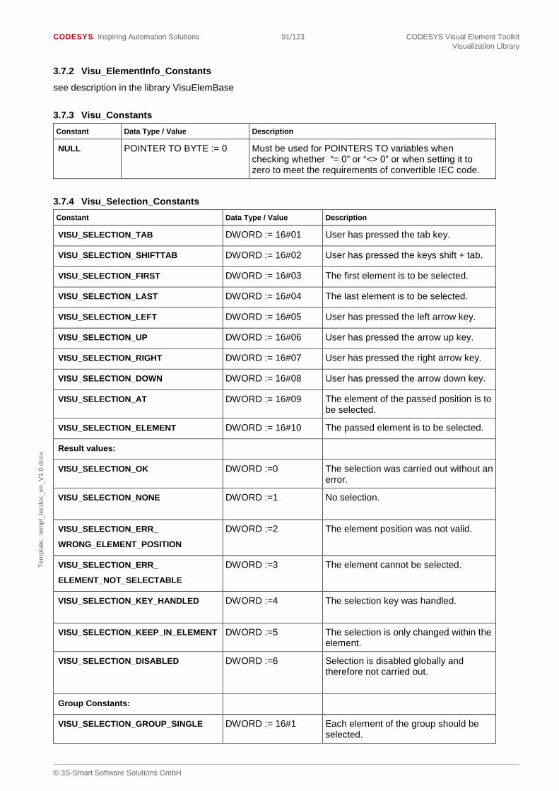
CODESYS Inspiring Automation Solutions 91/123 CODESYS Visual Element Toolkit Visualization Library
© 3S-Smart Software Solutions GmbH
Tem
plat
e: t
empl
_tec
doc_
en_V
1.0.
docx
3.7.2 Visu_ElementInfo_Constants
see description in the library VisuElemBase
3.7.3 Visu_Constants Constant Data Type / Value Description
NULL POINTER TO BYTE := 0 Must be used for POINTERS TO variables when checking whether “= 0” or “<> 0” or when setting it to zero to meet the requirements of convertible IEC code.
3.7.4 Visu_Selection_Constants Constant Data Type / Value Description
VISU_SELECTION_TAB DWORD := 16#01 User has pressed the tab key.
VISU_SELECTION_SHIFTTAB DWORD := 16#02 User has pressed the keys shift + tab.
VISU_SELECTION_FIRST DWORD := 16#03 The first element is to be selected.
VISU_SELECTION_LAST DWORD := 16#04 The last element is to be selected.
VISU_SELECTION_LEFT DWORD := 16#05 User has pressed the left arrow key.
VISU_SELECTION_UP DWORD := 16#06 User has pressed the arrow up key.
VISU_SELECTION_RIGHT DWORD := 16#07 User has pressed the right arrow key.
VISU_SELECTION_DOWN DWORD := 16#08 User has pressed the arrow down key.
VISU_SELECTION_AT DWORD := 16#09 The element of the passed position is to be selected.
VISU_SELECTION_ELEMENT DWORD := 16#10 The passed element is to be selected.
Result values:
VISU_SELECTION_OK DWORD :=0 The selection was carried out without an error.
VISU_SELECTION_NONE DWORD :=1 No selection.
VISU_SELECTION_ERR_
WRONG_ELEMENT_POSITION
DWORD :=2 The element position was not valid.
VISU_SELECTION_ERR_
ELEMENT_NOT_SELECTABLE
DWORD :=3 The element cannot be selected.
VISU_SELECTION_KEY_HANDLED DWORD :=4 The selection key was handled.
VISU_SELECTION_KEEP_IN_ELEMENT DWORD :=5 The selection is only changed within the element.
VISU_SELECTION_DISABLED DWORD :=6 Selection is disabled globally and therefore not carried out.
Group Constants:
VISU_SELECTION_GROUP_SINGLE DWORD := 16#1 Each element of the group should be selected.

CODESYS Inspiring Automation Solutions 92/123 CODESYS Visual Element Toolkit Visualization Library
© 3S-Smart Software Solutions GmbH
Tem
plat
e: t
empl
_tec
doc_
en_V
1.0.
docx
Constant Data Type / Value Description
VISU_SELECTION_GROUP_BLOCK DWORD := 16#2 Only the group itself is to be selected.
3.7.5 Text Flag Constants (not all constants available with symbolic names)
(For textalignment use VisuEnumHorizontalAlignment and VisuEnumVerticalAlignment)
Constant Data Type / Value
Description
VISU_DTF_AUTO_SHRINK_TEXT DWORD := 16#10
This option fits the text to the given rectangle width. If the text is too long the text is truncated and ... are added.
VISU_DTF_CALCULATE_RESULTING_POSITION DWORD := 16#20
After drawing the text the resulting position will be calculated and stored for subsequent paintcommands
VISU_DTF_DRAW_RELATIVE DWORD := 16#40
Not the passed absolute position will be used for drawing the text but the previously reached position (see VISU_DTF_CALCULATE_RESULTING_POSITION)
VISU_DTF_ROTATE DWORD := 16#80
Text will be drawn rotated (if supported) according to the orientation of the rectangle
VISU_DTF_LINEBREAK DWORD := 16#100
Use of automatic linebreak, if text is to long.
VISU_DTF_ELLIPSIS DWORD := 16#200
Automatic add of ending ‘…’, if text is to long.
TF_BGELEM DWORD := 16#80000000
A background element is drawn.
TF_WSTRING DWORD := 16#40000000
The string is a Wstring.
3.7.6 Image Flag Constants Constant Data Type /
Value Description
VISU_DBF_ISOTROPIC DWORD := 16#01
Scale type isotropic.
VISU_DBF_ANISOTROPIC DWORD := 16#02
Scale type anisotropic.
VISU_DBF_FIXED DWORD := 16#04
Scale type fixed.
VISU_DBF_SHOWFRAME DWORD := 16#08
Frame around the rectangle, marking the size of the image.
VISU_DBF_CLIPFRAME DWORD := 16#10
Only that part of the image fitting into the frame will be displayed. Use

CODESYS Inspiring Automation Solutions 93/123 CODESYS Visual Element Toolkit Visualization Library
© 3S-Smart Software Solutions GmbH
Tem
plat
e: t
empl
_tec
doc_
en_V
1.0.
docx
together with VISU_DBF_FIXED and VISU_DBF_SHOWFRAME.
VISU_DBF_TRANSPARENT DWORD := 16#20
Areas with the dwTransparentColor will be shown transparent.

CODESYS Inspiring Automation Solutions 94/123 CODESYS Visual Element Toolkit First Steps
© 3S-Smart Software Solutions GmbH
Tem
plat
e: t
empl
_tec
doc_
en_V
1.0.
docx
4 First Steps
For developing own visual elements, this chapter offers a step-by-step explanation for how to create the library, which objects needed to be inserted to the library and finally a step-by-step coding of a simple element. The element will at first be just a simple rectangle, which will get more functionality in the following chapters. The example is based on the function block VisuFbRectangularElement and the interface IvisualElement, which are both implemented in the VisuElemBase library.
When using CODESYS version 3.5.0.0 or newer ones, the developer toolkit is not integrated in CODESYS any more. You need to install the “CODESYS VisualElementToolkit” package before starting! To work with this package a restart of CODESYS is necessary.
When using CODESYS version 3.5.2.0 or newer ones, the developer toolkit is also protected by a license. To use the license, a dongle is needed.
Important: Before start, check some settings. To be able, to see all identifiers from the visualization libraries, have a look at chapter 2.5.
Some other settings have to be done in menu Tools, select “Options..”. Have a look at the settings for “IEC code converter”. Both paths, in “C# Conversion” and in “Java Conversion”, have to be set. A C# compiler is delivered with CODESYS. The Java conversion is obsolete and for that reason this setting is optional. For the Java Conversion a JDK (Java Development Kit) can be downloaded from Oracle. The settings can be as follow:
Example libraries:
Attached to the documentation find library “FirstStepElementsAndExamples”. This library includes all the steps that are described in the following pages.
There are also some additional examples in the library.
4.1 Create library and make basic settings
Create a new library with the shortcut “Create a new project…” or open the File-menu and choose “New Project”. The created library should have the extension “.library”. Maybe the “Project Environment”-window pops up. It can offer to update the compiler version, visualization profile or libraries versions. It’s recommended to update the versions or, for the visualization profile, set it to the one that is used.
Libraries may vary with the settings and objects they need. To start with we begin with the basic settings you always need to do:
Project Settings: Open via the POU-window or by menu Project – Project Settings. The Visualization Profile should be set to the newest existing profile.

CODESYS Inspiring Automation Solutions 95/123 CODESYS Visual Element Toolkit First Steps
© 3S-Smart Software Solutions GmbH
Tem
plat
e: t
empl
_tec
doc_
en_V
1.0.
docx
Project Information: Also in menu Project. Start in the “Summary”-tab. The first 3 lines need to be filled, Company, e.g.: “My company name”, Title, e.g.: “Visu First Step Elements”, Version, e.g.: 1.0.0.0 (Version has to be 4-digits). For better documentation also fill in the other lines. To reserve your own namespace you need to contact 3S-Smart Software Solutions GmbH. Important: In “Properties” add the key “VisuElements”, Type: Boolean, Value: TRUE. Please notice: the key “LanguageModelAttribute” is not working for a library at the moment, so please delete this entry to avoid problems. Starting with V3.5.10.0 a new key is available: “LoadLibrariesEvenInIntegratedVisu”. This key is only needed in a special case: an element that uses images from the imagepool of the library and should be used in the integrated visu. Normaly, the elementlibraries are not loaded in projects with integrated visu because of performance reasons. Therefore, the images would not be available. Use this 95oolean key with value TRUE and the library will be available in the integrated visu. Please notice: With active key, all elementlibraries will be loaded. Starting with V3.5.13.0 a new key is available: “AllowVisuLibraryRedirection” This key can be used with a boolen value “TRUE” if it is necessary to override one of the referenced visualization libraries using the placeholder dialog of the library manager. Visualization libraries can be overloaded using this dialog only if this setting is active in the currently open project. In fact this feature could be used for testing purposes within visualization projects too when the setting is defined in the according project. Please remark that this setting is intended only for testing or development purposes because then you are typically working with untested sets of libraries.
Some objects also need to be inserted. Select the new created library in the POU-window, right-click and choose “Add Object” or use the Project-menu and select “Add Object”. To start with the following objects are needed:
POU: After writing the name, e.g. FbSimpleElement, the type needs to be set to “Function Block”. Implements and Extends can be set here, or later in the code part itself. Implementation language is ST.
Text List: will be filled later. Name the list “TL_ElementProperties” for compatibility with other libraries.
Library Manager: Some libraries have to be inserted. As the basic libraries are always used with a placeholder, they are not inserted directly. If the menu-entry “Add Visual Element Development Libraries” does not exist, insert it via the Tools-menu, entry “Customize..”. Select the category “Visual Commands” to get the needed command. Insert the command into e.g. Tools or create a new menu-category. Now insert the libraries with the command, in the “Select Visualization Profile”-window choose the newest profile. This command will add all available visualization libraries. Important: As only “VisuInputs”, “VisuElemBase” and “VisuElems” (will maybe needed later) are needed, please delete the others again, to avoid later on errors. Additionally, the library “CmpVisuHandler” is needed.
4.2 Base class VisuFbRectangularElement
VisuFbRectangularElement can be used as base class for a new visual element. This base class implements IVisualElement, that needs to be used by every element. As well as IVisualElement3 VisuFbRectangularElement already offers functionality for most methods. By default, this element is created as a static element. All parts of the base class can be overridden. Please find an overview of the offered implementation in Implementation in VisuFbRectangularElement.
(Please notice: VisuFbElemSliderExample directly implements IvisualElement.)
The following variables are implemented in this base class:
FUNCTION_BLOCK VisuFbRectangularElement IMPLEMENTS IvisualElement VAR_INPUT {attribute...} m_StaticPosition : VisuStructRectangle; END_VAR VAR_OUTPUT EffectivePosition : VisuStructPaintRectangle; END_VAR VAR m_pCurrentClientData : POINTER TO VisuStructClientData; (* The following three variables must be set by the derived class *) m_bStaticElement : BOOL := TRUE; (* if this value is set, the element is completely static *) m_bVisible : BOOL := TRUE; m_iLineWidth : INT := 1;

CODESYS Inspiring Automation Solutions 96/123 CODESYS Visual Element Toolkit First Steps
© 3S-Smart Software Solutions GmbH
Tem
plat
e: t
empl
_tec
doc_
en_V
1.0.
docx
Important: Some information about special implementation in the main methods:
ElementInfo: for optimisation reasons, the element position is not known right from the beginning. Therefore, protInit is called from the method ElementInfo, and not from the method Initialize. This is ok, as long as the element is a static element.
The methods, that are mostly needed to be changed are already put together in a separate folder, called protected, the method-names have the prefix “prot”.
protElementInfo: can be overridden, if needed. Is called from method ElementInfo. Please remark: If you override this method, it is important that you explicitly initialize the return value with the value VISU_ELEMINFO_SERVICE_UNKNOWN to prevent returning 0 (->VISU_ELEMINFO_SERVICE_HANDLED_OK) accidentally.
protGetCurrentPosition: basic functionality exists, only needs to be overridden for elements, which can rotate. Is called from method GetUpdateRects.
protInit: has to be overridden, as it doesn’t offer basic functionality. Will be called from method ElementInfo. In most cases the method Initialize will be overridden too, to get a later call of protInit (see advanced element example).
protPaint: has to be overridden, as it doesn’t offer basic functionality. Paints the element. Is called from the method Paint, only if the element needs to be painted.
protUpdate: has to be overridden, as it doesn’t offer basic functionality. Update the elements. Is called from the method Update. Offline it is called always, online only for non-static elements.
The VisuFbRectangularElement is in the library VisuElemBase. Have a look in the library manager, to see the methods of the base class and find the implementation also in Implementation in VisuFbRectangularElement.
4.2.1 Ivisualization framework
CODESYS is providing a framework to call the visualization elements at runtime. Therefore a visualization element needs to use IvisualElement. The method calls in every cycle roughly work as follow:

CODESYS Inspiring Automation Solutions 97/123 CODESYS Visual Element Toolkit First Steps
© 3S-Smart Software Solutions GmbH
Tem
plat
e: t
empl
_tec
doc_
en_V
1.0.
docx
This means, if Checksum is not detecting changes, GetUpdateRects will not add the element to the painting queue. Therefore, the element will not be repainted.
4.3 Simple Element
4.3.1 Function Block
Now the coding can start. Use your function block, that was inserted earlier on in: Create library and make basic settings. The SimpleElement –Function Block (short: FB) gets its implements and extends information:
FUNCTION_BLOCK FbSimpleElement EXTENDS VisuFbRectangularElement IMPLEMENTS IvisualElement
The FB gets its attributes, which can be as follow:
{attribute ‘VisualElement’} {attribute ‘Name’ := ‘SimpleElement’} {attribute ‘NameTextId’ := ‘TL_ElementProperties.MyFirstElement’} {attribute ‘ElementType’ := ‘RectangleType’} {attribute ‘Category’ := ‘My Elements’} {attribute ‘SortFlag’ := ‘8100’} FUNCTION_BLOCK SimpleElement ....
The member variables used for the configuration of the element, are declared in the VAR_INPUT section. The position of the element, with x and y coordinates, width and height, is already declared in the VisuFbRectangularElement in the variable m_StaticPosition. For the beginning only one variable with its attributes is added to the FB:
{attribute ‘Category’ := ‘Simple|Standard’} {attribute ‘Animation’} {attribute ‘DisplayTextId’ := ‘TL_ElementProperties.Variable’} {attribute ‘ieccodeconversion_datatype’:= ‘VisuElemBase.VisuFbAnalyzeNumVarConverted’} {attribute ‘DescriptionTextId’:=’TL_ElementProperties.Desc_VariableValue’} m_pVariable : POINTER TO VisuFbAnalyzeNumVar;
4.3.2 Insert protInit, protPaint and protUpdate
Now add a folder, called protected, and the methods protInit, protPaint and protUpdate to the FB, like in the base class. A method is added by selecting the new folder, Add Object, Method. The return value of each method is of type bool.
protInit also needs the following Var_Input-variable: parentVisu: Ivisualization;
protPaint needs dwFlags: DWORD; as input-varible.

CODESYS Inspiring Automation Solutions 98/123 CODESYS Visual Element Toolkit First Steps
© 3S-Smart Software Solutions GmbH
Tem
plat
e: t
empl
_tec
doc_
en_V
1.0.
docx
4.3.3 Method protPaint
To paint a rectangle, some code needs to be added. A rectangle will be painted with DrawRect or DrawRectUnchecked. First some local variables are added.
VAR Colors : VisuStructColors; currentLook : VisuStructElementLook; currentPosition : VisuStructPaintRectangle; END_VAR
The variables are set in the method-body, e.g. with the following values:
currentLook.dwFillFlags := VisuEnumBrushStyle.BS_SOLID; currentLook.dwFrameFlags := VisuEnumPenStyle.PS_SOLID; currentLook.iLineWidth := 1; Colors.dwFillColor := COLOR_WHITE; Colors.dwFrameColor := 16#FF000000;
For the DrawRect-method, the painting position is needed as a variable of type VisuStructPaintRectangle. Therefore transform the m_StaticPosition as follow:
Add a new function FctGetpaintRectangle:
The function needs the following header and body:

CODESYS Inspiring Automation Solutions 99/123 CODESYS Visual Element Toolkit First Steps
© 3S-Smart Software Solutions GmbH
Tem
plat
e: t
empl
_tec
doc_
en_V
1.0.
docx
Now you can call the function FctGetPaintRectangle(m_StaticPosition, ADR(currentPosition));
At last call the painting method: m_pCurrentClientData^.GlobalData.DrawingContext.DrawRectUnchecked(currentPosition, VisuEnumSimpleType.VISU_ST_RECTANGLE, currentLook, Colors, TRUE, m_pCurrentClientData, ADR(m_pCurrentClientData^.PaintBuffer));
4.3.4 Textlist (TL_ ElementProperties)
The textlist provides the possibility to use texts in different languages (see also for more information). To add more languages to the textlist, select the first line, right-click, Add Language, and insert “de” for German and a second time “en” for English. For all attributes in the FB, that refer to the textlist, have to be an entry in the textlist. If texts are missing, there will be a warning, when checking the visual element.
To save the library use “Save Project And Install Into Library Repository”. The library is not yet working.
4.3.5 Check visual element
To check the code for syntax errors, the command: “Check Visual Elements” is needed. Install it via Tools – Customize, choose category: Visual Commands. Always do “Save Project And Install Into Library Repository” before “Check Visual Elements”.
4.3.6 Insert bitmap for display in toolbox Right-click on the FB in the POU-window, open “Properties” and select “Bitmap”. Here the bitmap can be inserted. The size of the bitmap has to be 16 x 16 pixels. The background of the bitmap can be set to transparent. Check “Render pixels of this color transparently” and select the color that is set as backgroundcolor in the button at the right.
Since CODESYS Version V3.5.7 a new possibility can be used to set an image for the toolbox.
1. Create an ImagePool object e.g. IP_ElementImages 2. Set the properties
Set “Exclude from build” in the “Build” tab. Set the following options in the “ImagePool” tab.
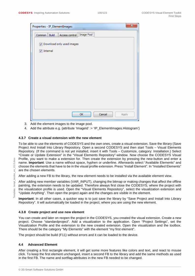
CODESYS Inspiring Automation Solutions 100/123 CODESYS Visual Element Toolkit First Steps
© 3S-Smart Software Solutions GmbH
Tem
plat
e: t
empl
_tec
doc_
en_V
1.0.
docx
3. Add the element images to the image pool. 4. Add the attribute e.g. {attribute ‘ImageId’ := ‘IP_ElementImages.Histogram’}
4.3.7 Create a visual extension with the new element
To be able to use the elements of CODESYS and the own ones, create a visual extension. Save the library (Save Project And Install Into Library Repository. Open a second CODESYS and then start Tools – Visual Elements Repository. (If the command is not yet installed, insert it with Tools – Customize, category: Installation.) Select “Create or Update Extension” in the “Visual Elements Repository”-window. Now choose the CODESYS Visual Profile, you want to make a extension for. Then create the extension by pressing the new-button and enter a name. Important: Use a name without space, hyphen or underline. Afterwards select “Available Elements” and choose the elements that have to be in the visual profile extension. Press “Install Element”. In “Installed Elements” are the chosen elements.
After adding a new FB to the library, the new element needs to be installed via the available element view.
After adding new member variables (VAR_INPUT), changing the bitmap or making changes that affect the offline painting, the extension needs to be updated. Therefore always first close the CODESYS, where the project with the visualization profile is used. Open the “Visual Elements Repository”, select the visualization extension and “Update Anything”. Then open the project again and the changes are visible in the element.
Important: In all other cases, a quicker way is to just save the library by “Save Project and Install Into Library Repository”. It will automatically be loaded in the project, where you are using the new element.
4.3.8 Create project and use new element
You can create and later on reopen the project in the CODESYS, you created the visual extension. Create a new project. Choose “standardproject”. Add a visualization to the application. Open “Project Settings”, set the Visualization Profile and the extension to the new created extension. Open the visualization and the toolbox. There should be the category “My Elements” with the element “my first element”.
The project should be build (F11) without errors and it can be loaded to the device.
4.4 Advanced Element
After creating a first rectangle element, it will get some more features like colors and text, and react to mouse click. To keep the first element unchanged, insert a second FB to the library and add the same methods as used in the first FB. The name and sortflag-attributes in the new FB needed to be changed.

CODESYS Inspiring Automation Solutions 101/123 CODESYS Visual Element Toolkit First Steps
© 3S-Smart Software Solutions GmbH
Tem
plat
e: t
empl
_tec
doc_
en_V
1.0.
docx
4.4.1 Advanced element colors
The advanced element should offer the option to select the color in the toolbox. Therefore we add a member-variable (variable in the VAR_INPUT section) to the FB. The entry can be as follow, with default settings for the color values, which are written in two different possible ways, the first one written in hexadecimal, the second one using a global variable.
{attribute ‘Category’ := ‘Color|Standard’} {attribute ‘DisplayTextId’ := ‘TL_ElementProperties.Colors’} {attribute ‘DescriptionTextId’ := ‘TL_ElementProperties.Desc_Colors’} m_Colors : VisuStructColors := (dwFrameColor := 16#FF000000, dwFillColor := Visu_Constants.COLOR_BLUE);
The VAR section of the FB gets a variable for internal use:
EffectiveColors : VisuStructColors;
ProtInit and protUpdate set the variable: EffectiveColors := m_Colors;
ProtPaint is using EffectiveColors instead of Colors.
4.4.1.1 Override method Initialize
The VisuFbRectangularElement, which is used as base class, offers methods for a static element. For reacting to color changes in offline-mode, the Initialize-method needs to be overwritten. Add a new method, name it Initialize and insert the following code:
Code for header:
METHOD Initialize : BOOL VAR_INPUT parentVisu : Ivisualisation; END_VAR
Code for body:
m_ParentVisu := parentVisu; protInit(parentVisu);
Important: The base class calls protInit out of the method ElementInfo. As there is now a second call of protInit, we add a 101verrid variable to secure the initialization is done only once. We also check, if the element position is already set as this is not the case in one of the calls due to performance reasons! Add m_bInit : BOOL := TRUE; to the Var-section of the FB and change the protInit as follow:
IF m_bInit AND m_StaticPosition.iHeight <> 0 AND m_StaticPosition.iWidth <> 0 THEN EffectiveColors := m_Colors; m_bInit := FALSE; END_IF
After updating the textlist, the visualization profile can be updated. The two elements should be visible in the project. There should be no errors when going online.
4.4.2 Advanced element text and tooltip
The advanced element gets text, tooltip and text variables.
4.4.2.1 Add member variables (VAR_INPUT) for text and complete protPaint
The code for the FB can be as follow:
{attribute ‘Editable’ := ‘False’} {attribute ‘Visible’ := ‘False’} {attribute ‘TextIdNode’}

CODESYS Inspiring Automation Solutions 102/123 CODESYS Visual Element Toolkit First Steps
© 3S-Smart Software Solutions GmbH
Tem
plat
e: t
empl
_tec
doc_
en_V
1.0.
docx
{attribute ‘AllocateText’ := ‘String’} _pstTextId : Visu_TypeString; {attribute ‘Editable’ := ‘False’} {attribute ‘Visible’ := ‘False’} {attribute ‘TooltipIdNode’} {attribute ‘AllocateText’ := ‘String’} _pstTooltipId : Visu_TypeString; {attribute ‘Category’ := ‘Simple|Standard|Texts’} {attribute ‘DisplayTextId’ := ‘TL_ElementProperties.Texts’} {attribute ‘DescriptionTextId’ := ‘TL_ElementProperties.Desc_TextsFormatStrings’} m_StaticTexts : VisuStructStaticTexts; {attribute ‘Animation’} {attribute ‘Category’ := ‘Texts’} {attribute ‘DisplayTextId’ := ‘TL_ElementProperties.TextVariables’} {attribute ‘ieccodeconversion_datatype’ := ‘VisuElemBase.VisuFbAnalyzeTextVarsConverted’} {attribute ‘DescriptionTextId’ := ‘TL_ElementProperties.Desc_TextVariables’} m_pTextChanges : POINTER TO VisuFbAnalyzeTextVars;
Add a variable “EffectiveTexts” of type VisuStructElementTexts to the FB and update the variable in the protUpdate-method.
EffectiveTexts.pstText := m_StaticTexts.pstText;
EffectiveTexts.pstToolTip := m_StaticTexts.pstToolTip;
If a text is set, it needs to be painted. If text variables are set, they also need to be regarded. The additional code for the method protPaint can be as follow:
New local variables:
{attribute ‘ieccodeconversion_character_array’} pTemp : POINTER TO BYTE; dwTemp : DWORD; Additional code:
IF Visu_FctStrlen(EffectiveTexts.pstText) > 0 THEN IF m_pTextChanges <> NULL THEN pTemp := ADR(g_VisuTextBuffer); dwTemp := Visu_Constants.VISU_TEXTBUFFER_SIZE;
m_pTextChanges^ (_EffectiveTexts := EffectiveTexts, pBuffer := pTemp, dwBufferSize := dwTemp);
END_IF m_pCurrentClientData^.GlobalData.DrawingContext.DrawTextUnchecked(currentPosition, currentFont, EffectiveTexts.pstText, g_bWstring, VisuEnumHorizontalAlignment.HCENTER OR VisuEnumVerticalAlignment.VCENTER, TRUE, m_pCurrentClientData, ADR(m_pCurrentClientData^.PaintBuffer)); END_IF
4.4.2.2 Overwrite method SetStaticState
Important: With configuring the text to e.g. “%s” and the text variable to a variable that exists in the project, text changes are possible during online-mode. Therefore the element needs to change its static state. Overwrite the method SetStaticState of the base class with the following code: m_bStaticElement := FALSE; The variable m_bStaticElement is member of the base class.
4.4.2.3 Overwrite method Checksum
Important: The method Checksum also needs to be overwritten. The method Checksum signals, if a repaint is necessary. If the Checksum return-value is different from the last call, the element will be repainted. Therefore, every variable, that will cause optical changes for the element, needs to be included to the Checksum-method. For the above example insert the following code:
IF m_pTextChanges <> NULL THEN

CODESYS Inspiring Automation Solutions 103/123 CODESYS Visual Element Toolkit First Steps
© 3S-Smart Software Solutions GmbH
Tem
plat
e: t
empl
_tec
doc_
en_V
1.0.
docx
Checksum := VisuFctAddChecksum (Checksum, m_pTextChanges^.Checksum()); END_IF
4.4.2.4 Overwrite method HandleInput
To display the tooltip, some more extensions are needed. Add an input-handler to the Var-part of the FB. Elements that have an input-configuration save the m_pInputHandler as Var_input.
M_pInput : VisuFbButtonInput;
m_pInputHandler : POINTER TO VisuFbInputBase2 := ADR(m_pInput);
The HandleInput of the base class also needs to be overwritten. Add a method with the following code for the header: METHOD HandleInput : BOOL VAR_INPUT pEvent : POINTER TO VisuStructEvent; END_VAR VAR pInput2 : POINTER TO VisuFbInputBase2 := m_pInputHandler; END_VAR The body of the method gets the following code: IF m_pInputHandler <> NULL THEN IF _iElemNr >= 0 THEN
HandleInput := pInput2^.ExecuteEvent(pEvent, m_pCurrentClientData, THIS^, _iElemNr);
END_IF END_IF
_iElemNr is a variable from the base class.
For the type VisuStructEvent a new library needs to be added. Open the library manager, click “Add library..” on the right side. The library is added as placeholder, so therefore select that tab. Placeholder name and library name is “CmpVisuHandler”.
After updating textlist and visualization profile, the element should work correct in the project.
4.4.3 React to mouse click
Some input-configurations can be set in the element toolbox, others need to be done by coding.
For the first case insert the following code to Var_input of the FB:
{attribute ‘Visible’ := ‘False’} {attribute ‘DirectlyAssignable’} {attribute ‘Input’} {attribute ‘ComplexInputs’ := ‘Toggle, Tap’} m_pInputHandler : POINTER TO VisuFbInputBase2;
The earlier on inserted m_pInputHandler in the FB is not needed any more.
For other elements may some additional coding be necessary. E.g. a checkbox-element needs to paint a different bitmap, a button needs to look pressed or released, a drop-down-box needs to show or hide the list or the variable value needs to be changed.
The advanced element will react to a mouse-click like a color-taper. With mouse-down, frame-color and fill-color will change, with mouse-up, the colors change back.
Before changing the HandleInput-method, two new variables are inserted to the var-section of the FB:
m_bDoColorChange : BOOL; m_iColorChange : INT := 10;
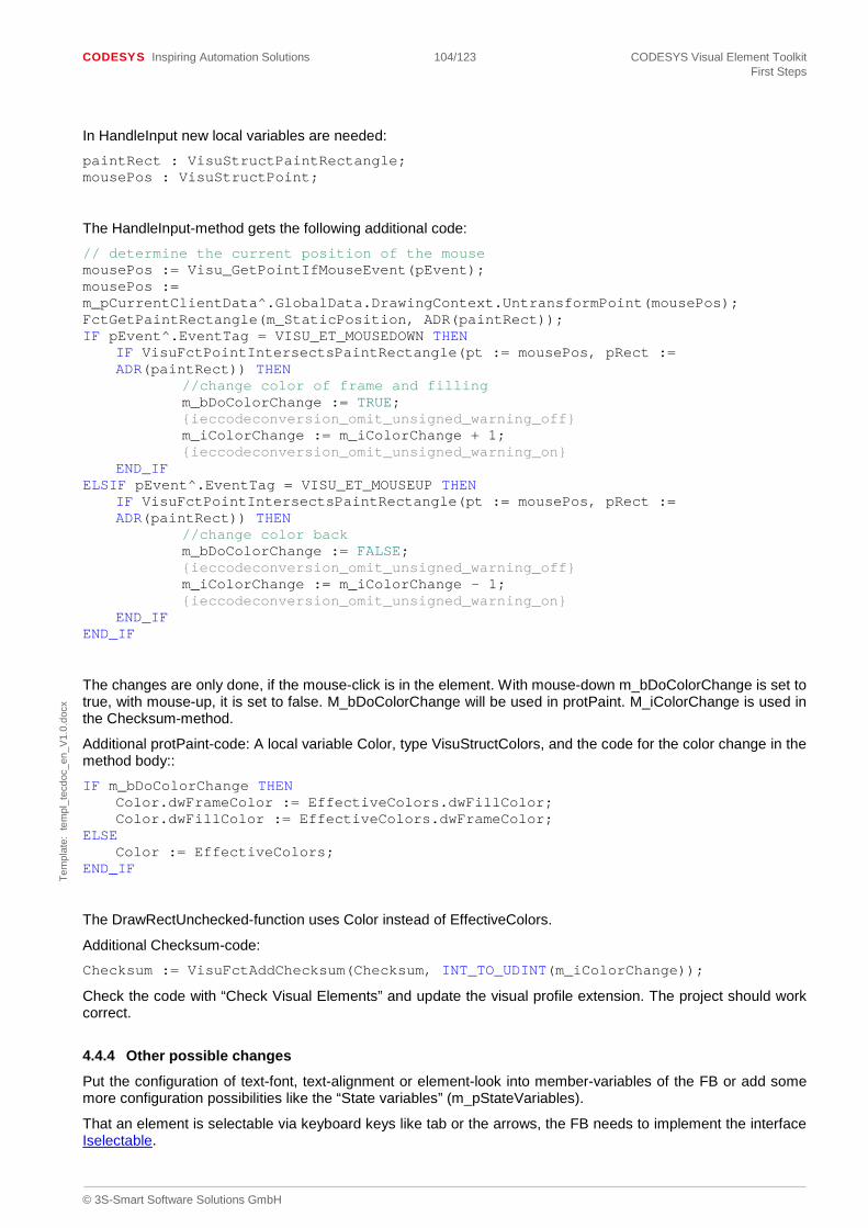
CODESYS Inspiring Automation Solutions 104/123 CODESYS Visual Element Toolkit First Steps
© 3S-Smart Software Solutions GmbH
Tem
plat
e: t
empl
_tec
doc_
en_V
1.0.
docx
In HandleInput new local variables are needed:
paintRect : VisuStructPaintRectangle; mousePos : VisuStructPoint;
The HandleInput-method gets the following additional code:
// determine the current position of the mouse mousePos := Visu_GetPointIfMouseEvent(pEvent); mousePos := m_pCurrentClientData^.GlobalData.DrawingContext.UntransformPoint(mousePos); FctGetPaintRectangle(m_StaticPosition, ADR(paintRect)); IF pEvent^.EventTag = VISU_ET_MOUSEDOWN THEN
IF VisuFctPointIntersectsPaintRectangle(pt := mousePos, pRect := ADR(paintRect)) THEN
//change color of frame and filling m_bDoColorChange := TRUE; {ieccodeconversion_omit_unsigned_warning_off} m_iColorChange := m_iColorChange + 1; {ieccodeconversion_omit_unsigned_warning_on}
END_IF ELSIF pEvent^.EventTag = VISU_ET_MOUSEUP THEN
IF VisuFctPointIntersectsPaintRectangle(pt := mousePos, pRect := ADR(paintRect)) THEN
//change color back m_bDoColorChange := FALSE; {ieccodeconversion_omit_unsigned_warning_off} m_iColorChange := m_iColorChange – 1; {ieccodeconversion_omit_unsigned_warning_on} END_IF END_IF
The changes are only done, if the mouse-click is in the element. With mouse-down m_bDoColorChange is set to true, with mouse-up, it is set to false. M_bDoColorChange will be used in protPaint. M_iColorChange is used in the Checksum-method.
Additional protPaint-code: A local variable Color, type VisuStructColors, and the code for the color change in the method body::
IF m_bDoColorChange THEN Color.dwFrameColor := EffectiveColors.dwFillColor; Color.dwFillColor := EffectiveColors.dwFrameColor; ELSE Color := EffectiveColors; END_IF
The DrawRectUnchecked-function uses Color instead of EffectiveColors.
Additional Checksum-code:
Checksum := VisuFctAddChecksum(Checksum, INT_TO_UDINT(m_iColorChange));
Check the code with “Check Visual Elements” and update the visual profile extension. The project should work correct.
4.4.4 Other possible changes
Put the configuration of text-font, text-alignment or element-look into member-variables of the FB or add some more configuration possibilities like the “State variables” (m_pStateVariables).
That an element is selectable via keyboard keys like tab or the arrows, the FB needs to implement the interface Iselectable.

CODESYS Inspiring Automation Solutions 105/123 CODESYS Visual Element Toolkit First Steps
© 3S-Smart Software Solutions GmbH
Tem
plat
e: t
empl
_tec
doc_
en_V
1.0.
docx
4.5 Some helpful functions
4.5.1 For using values from the style
VisuFctGetStyleType()
Returns the type of the currently selected style as value of type ‘VisuEnumStyleType’. This type is used for the basic look of the elements, as shown in Visualization styles.
Get other style values:
With the global variable g_VisualizationStyle of type IvisualizationStyle different style values like colors, fonts, strings or integer can be achieved. The offered methods need the name of the style entry as string, a default value and an optional value to get an result error code.
Example: dwDefaultColor := 16#FFFFFFFF; // ELEMENT_FILL_COLOR : STRING := ‘Element-Fill-Color’; EffectiveColors.dwFillColor := g_VisualizationStyle.GetColor (ELEMENT_FILL_COLOR, dwDefaultColor, NULL);
4.5.2 Format a real variable
See library VisuElemBase: VisuFbPrintfRealVar
Example:
/// Helper class, that formats real variables using a custom format string {attribute ‘ieccodeconversion_datatype’ := ‘VisuElemBase.VisuFbPrintfRealVarConverted’} m_PrintfRealVar : VisuFbPrintfRealVar; // A variable, that is used to create the labels m_pstLabel : STRING(50); // A variable, that is used to create the labels (for unicodes) m_pstLabelW : WSTRING(50); LABEL_BUFFER_SIZE : UINT := 50; LABEL_BUFFER_SIZE_W : UINT := 100; // can be %3.2f, %i, %s,.. m_FormatString : STRING; rValue:= m_pVariable^.GetValue(); m_PrintfRealVar.SetVariable(ADR(rValue)); IF g_bWstring THEN m_PrintfRealVar.pBuffer := ADR(m_pstLabelW); m_PrintfRealVar.dwBufferSize := LABEL_BUFFER_SIZE_W; m_PrintfRealVar.PrintfW(ADR(m_FormatString)); ELSE m_PrintfRealVar.pBuffer := ADR(m_pstLabel); m_PrintfRealVar.dwBufferSize := LABEL_BUFFER_SIZE; m_PrintfRealVar.Printf(ADR(m_FormatString)); END_IF pstLabel := m_PrintfRealVar.pBuffer; m_pCurrentClientData^.GlobalData.DrawingContext.DrawTextUnchecked(currentPosition, currentFont, pstLabel, g_bWstring, VisuEnumHorizontalAlignment.HCENTER OR VisuEnumVerticalAlignment.VCENTER, TRUE, m_pCurrentClientData, ADR(m_pCurrentClientData^.PaintBuffer));
4.5.3 For working with time/ date values
Use library SysTimeRTC.
Example:
dwtimestamp : DWORD; // time in UTC retcode : UDINT;

CODESYS Inspiring Automation Solutions 106/123 CODESYS Visual Element Toolkit First Steps
© 3S-Smart Software Solutions GmbH
Tem
plat
e: t
empl
_tec
doc_
en_V
1.0.
docx
pDate : SysTimeRtc.SYSTIMEDATE; // entire body of function can be ignored from conversion, because this // method is implemented externally {ieccodeconversion_omit_conversion_on}//CHECKED_OMIT retcode := SysTimeRtc.SysTimeRtcConvertUtcToDate(dwtimestamp, pDate); {ieccodeconversion_omit_conversion_off}
4.6 Implementation in VisuFbRectangularElement
Additional an overview of the methods in VisuFbRectangularElement and their implementation. Please find more information of the base class VisuFbRectangularElement.
4.6.1 Checksum
Header:
METHOD Checksum : VisuTypeChecksum
Body: empty
This method is used for checking, if the element has to be redrawn. It is not a method of IvisualElement, but used as standard-function in visual element functionblocks.
The Method adds up the checksum for the values, that can change and will render the drawing, like the variable value. Use VisuFctAddChecksum for this. The return value is the checksum as VisuTypeChecksum. This value is used in the method GetUpdateRects.
4.6.2 ContainsPoint
Header: METHOD ContainsPoint : BOOL VAR_INPUT pt : VisuStructPoint; END_VAR VAR transformedRect : VisuStructPaintRectangle; END_VAR
Body:
transformedRect := m_pCurrentClientData^.GlobalData.DrawingContext.TransformPaintRect (EffectivePosition);
ContainsPoint := VisuFctPointIntersectsPaintRectangle (pt, ADR (transformedRect));
4.6.3 Destruct
Header: (* This method will be removed and replaced with a implicit Destructor (opposite to Init)*) METHOD Destruct : BOOL
Body: empty
4.6.4 ElementInfo
Header: METHOD ElementInfo : INT VAR_INPUT pData : POINTER TO Visu_StructElementInfo; END_VAR

CODESYS Inspiring Automation Solutions 107/123 CODESYS Visual Element Toolkit First Steps
© 3S-Smart Software Solutions GmbH
Tem
plat
e: t
empl
_tec
doc_
en_V
1.0.
docx
VAR resTemp : INT; END_VAR
Body: // As we do not have an input (if necessary, use accordingly derived class instead), we pass TRUE, FALSE => InputDeactivated, No Input Handler here ElementInfo := Visu_FctElementInfo_Simple(pData, NOT m_bVisible, FALSE, FALSE, _iElemNr, m_StaticPosition); IF pData^.iRequestedInfo = VISU_ELEMINFO_ASSIGNINITVALUES THEN // Notify derived classes that the position was assigned correctly now by // calling this init method protInit(m_ParentVisu); END_IF resTemp := protElementInfo(pData); IF resTemp <> VISU_ELEMINFO_SERVICE_HANDLED_ERROR_NOTIMPL THEN ElementInfo := resTemp; END_IF
4.6.5 GetClientData
Header: METHOD GetClientData : POINTER TO VisuStructClientData Body: GetClientData := m_pCurrentClientData;
4.6.6 GetSurroundingRect Header: METHOD GetSurroundingRect : VisuStructSimpleRectangle Body: GetSurroundingRect := VisuFctPaintRectCalculateSurroundingRect(EffectivePosition);
4.6.7 GetText
Header: (* Returns the text of the element*) METHOD GetText : Visu_TypeString Body: GetText := NULL;
4.6.8 GetTextProperties Header: METHOD GetTextProperties : BOOL VAR_OUTPUT Font : VisuStructFont; /// returns the alignment dwOptAlignment : DWORD; /// returns the flags, eg if pText points to WSTRING dwFlags : DWORD; END_VAR Body: GetTextProperties := FALSE;

CODESYS Inspiring Automation Solutions 108/123 CODESYS Visual Element Toolkit First Steps
© 3S-Smart Software Solutions GmbH
Tem
plat
e: t
empl
_tec
doc_
en_V
1.0.
docx
4.6.9 GetTooltip Header: (* Returns the tooltip of the element*) METHOD GetTooltip : Visu_TypeString Body: GetTooltip := NULL;
4.6.10 GetUpdateRects Header: METHOD GetUpdateRects : BOOL VAR_INPUT elemIndex : INT; (* parameter *) END_VAR VAR pElementry : POINTER TO VisuStructElementClientDataEntry; currentPosition : VisuStructSimpleRectangle; checksumx : VisuTypeCheckSum; END_VAR Body: IF NOT m_bStaticElement THEN IF NOT Visu_FctCheckElemIndexAccess(elemIndex, VISU_ELEMENTCOUNT) THEN RETURN; END_IF checksumx := Checksum (); pElementry := ADR (m_pCurrentClientData^.ElementsData.pElementsEntry^[elemIndex]); IF checksumx <> pElementry^.OldChecksum THEN (* some properties have changed *) currentPosition := protGetCurrentPosition(); m_pCurrentClientData^.GlobalData.CurrentUpdateRects.AddSimpleRect (ADR (currentPosition)); (* set new values to pClientData^ *) pElementry^.OldChecksum := checksumx; IF pElementry^.pOldRectangle <> NULL THEN IF NOT VisuFctCompareSimpleRectangles (pElementry^.pOldRectangle^, currentPosition) THEN (* element moved so invalidate a second rectangle *) m_pCurrentClientData^.GlobalData.CurrentUpdateRects.AddSimpleRect (ADR (pElementry^.pOldRectangle^)); END_IF pElementry^.pOldRectangle^ := currentPosition; END_IF END_IF END_IF
4.6.11 HandleInput Header: METHOD HandleInput : BOOL VAR_INPUT pEvent : POINTER TO VisuStructEvent; END_VAR
Body: HandleInput := VisuFctHandleInputWithoutInputHandler(pEvent, m_pCurrentClientData, m_IVE);

CODESYS Inspiring Automation Solutions 109/123 CODESYS Visual Element Toolkit First Steps
© 3S-Smart Software Solutions GmbH
Tem
plat
e: t
empl
_tec
doc_
en_V
1.0.
docx
4.6.12 Initialize Header: METHOD Initialize : BOOL VAR_INPUT parentVisu : Ivisualisation; END_VAR Body: m_ParentVisu := parentVisu
4.6.13 Paint Header: METHOD Paint : BOOL VAR_INPUT dwFlags : DWORD; END_VAR VAR currentPosition: VisuStructPaintRectangle; END_VAR Body: IF m_bVisible THEN IF VisuFctIsElementToDraw(dwFlags, m_bStaticElement) THEN (* element has to be drawn in current context *) currentPosition := EffectivePosition; Visu_FitPaintRectToLineWidth(ADR(currentPosition), m_iLineWidth);
IF m_pCurrentClientData^.GlobalData.DrawingContext.IsToUpdateRectangle(currentPosition, m_pCurrentClientData) THEN
Paint := protPaint(dwFlags); END_IF END_IF END_IF
4.6.14 SetClientData Header: METHOD SetClientData : BOOL VAR_INPUT pClientData : POINTER TO VisuStructClientData; END_VAR Body: m_pCurrentClientData := pClientData;
4.6.15 SetStaticState Header: METHOD SetStaticState : BOOL Body: m_bStaticElement := TRUE; SetStaticState := m_bStaticElement;
4.6.16 Update Header: METHOD Update : BOOL VAR ptBottomRight : VisuStructPoint; ptTopLeft : VisuStructPoint; END_VAR

CODESYS Inspiring Automation Solutions 110/123 CODESYS Visual Element Toolkit First Steps
© 3S-Smart Software Solutions GmbH
Tem
plat
e: t
empl
_tec
doc_
en_V
1.0.
docx
Body: (* these instructions have to happen for all elements *) ptTopLeft.iX := m_StaticPosition.iX; ptTopLeft.iY := m_StaticPosition.iY; IF m_pCurrentClientData^.GlobalData.ClientPaintVersion < VISU_CLIENTVERSION_CORRECTED_RECT_DIMENSION THEN ptBottomRight.iX := m_StaticPosition.iX + m_StaticPosition.iWidth – 1; ptBottomRight.iY := m_StaticPosition.iY + m_StaticPosition.iHeight – 1; ELSE ptBottomRight.iX := m_StaticPosition.iX + m_StaticPosition.iWidth; ptBottomRight.iY := m_StaticPosition.iY + m_StaticPosition.iHeight; END_IF VisuFctSetPaintRectangle (ptTopLeft, ptBottomRight, ADR (EffectivePosition)); // Offline the protUpdate must always be called to get the configured // properties IF NOT m_bStaticElement OR NOT g_bVisualizationOnline THEN Update := protUpdate(); END_IF
4.6.17 protElementInfo Header: METHOD protElementInfo : INT VAR_INPUT pData : POINTER TO Visu_StructElementInfo; END_VAR Body: // can be implemented in the derived class protElementInfo := VISU_ELEMINFO_SERVICE_HANDLED_ERROR_NOTIMPL;
4.6.18 protGetCurrentPosition Header: /// This method must be 110verridden when a rotation of the rectangle is done. /// In all other cases m_iLineWidth of the base class must be set from the /// derived class. METHOD protGetCurrentPosition : VisuStructSimpleRectangle VAR currentPosition : VisuStructSimpleRectangle; clipRect : VisuStructSimpleRectangle; bIsClipped : BOOL; END_VAR Body: IF m_pCurrentClientData^.GlobalData.DrawingContext.GetCurrentClipRect (ADR (clipRect)) THEN bIsClipped := TRUE; END_IF currentPosition := VisuFctPaintRectCalculateSurroundingRect (m_pCurrentClientData^.GlobalData.DrawingContext.TransformPaintRect (EffectivePosition)); Visu_FitSimpleRectToLineWidth(ADR(currentPosition), m_iLineWidth); // return only intersection with current clipping IF bIsClipped THEN currentPosition := VisuFctGetIntersectSimpleRectangle (ADR (currentPosition), ADR (clipRect)); END_IF protGetCurrentPosition := currentPosition;

CODESYS Inspiring Automation Solutions 111/123 CODESYS Visual Element Toolkit First Steps
© 3S-Smart Software Solutions GmbH
Tem
plat
e: t
empl
_tec
doc_
en_V
1.0.
docx
4.6.19 protInit Header: METHOD protInit : BOOL VAR_INPUT parentVisu : Ivisualisation; END_VAR Body: empty
4.6.20 protPaint Header: METHOD protPaint : BOOL VAR_INPUT dwFlags : DWORD; END_VAR Body: empty
4.6.21 protUpdate
Header:
METHOD protUpdate : BOOL
Body: empty
4.6.22 GetCompleteSurroundingRect
Header:
METHOD GetCompleteSurroundingRect : VisuStructSimpleRectangle
VAR
PositionBuffer : VisuStructPaintRectangle;
END_VAR
Body:
// Element size depending on current style: // ?, in case of yes, method has to be overwritten // Element size depending on line width: // Some elements get painted enlarged with a changed frame width, e.g. rectangle element // For this base element, we expect to have no frame, that can change the element size. // in case of different behaviour, method has to be overwritten // Hollow line width: size as configured (?) // Element size depending on other settings: // ?, in case of yes, method has to be overwritten // Dynamic position variables in the element: // ?, in case of yes, method has to be overwritten // Static rotation: // ?, in case of yes, method has to be overwritten

CODESYS Inspiring Automation Solutions 112/123 CODESYS Visual Element Toolkit First Steps
© 3S-Smart Software Solutions GmbH
Tem
plat
e: t
empl
_tec
doc_
en_V
1.0.
docx
// Use the static position. As this method will also be called offline, where the effective position is not yet used and set (Update has not been called). Visu_FctGetPaintRectangle(m_StaticPosition, ADR(PositionBuffer)); (* // Consider using following helper method: // (the changes by frame/line width have to be done by the element itself. The method handles static rotation and dynamic movement) GetCompleteSurroundingRect := VisuFctCalculateCompleteSurroundingRect( ADR(PositionBuffer), m_StaticPosition.m_iAngle, ADR(m_StaticCenter), m_pAbsoluteAnimation, m_pRelativeAnimation); *) GetCompleteSurroundingRect := VisuFctPaintRectCalculateSurroundingRect(PositionBuffer);
4.7 Additional examples in the library FirstStepElementsAndExamples
Additional examples can be found in the folder “AdditionalExamples”. These examples can be only code snippets or working elements.
4.7.1 Element with VisuFbAnalyzeTwoDimensionalArray
Starting with V3.5.4.0 there is a new animation function block. How to use this, is shown in the AdvancedElement3 – function block.
4.7.2 VisuFbRectangularElem
A simple rectangle element, that is implementing IvisualElement directly.
4.7.3 VisuFbElemSliderExample
A Slider element, that is implementing IvisualElement directly. This element is more complex and has more properties, that are shown in the visual editor.
4.8 Link visu elements with interfaces
CODESYS 3.5 SP4 introduced a new possibility to link visu elements with interfaces
Example:
A trend element can be attached with a visu element used to select the time (“time selector”), that has
to be displayed on the x axis. This can be simply achieved by some attributes
• Trend element
{attribute ‘AttachedInstanceVariable’ = ‘m_itfTimeSelector’} {attribute ‘AttachedInstanceType’ = ‘ItimeSelector’}

CODESYS Inspiring Automation Solutions 113/123 CODESYS Visual Element Toolkit First Steps
© 3S-Smart Software Solutions GmbH
Tem
plat
e: t
empl
_tec
doc_
en_V
1.0.
docx
{attribute ‘EditorType’ = ‘AttachedElementInstance’} m_sTimeSelectorInstanceName : STRING;
{attribute ‘Visible’ = ‘FALSE’} m_itfTimeSelector : ItimeSelector;
• Time selector
{attribute ‘AttachedInstanceVariable’ = ‘m_itfTimeSelectorClient’} {attribute ‘AttachedInstanceType’ = ‘ItimeSelectorClient’} {attribute ‘EditorType’ = ‘AttachedElementInstance’} m_sTimeSelectorClientInstanceName : STRING;
{attribute ‘Visible’ = ‘FALSE’} m_itfTimeSelectorClient : ItimeSelectorClient;
The interfaces ItimeSelector and ItimeSelectorClient contain the methods, that are used for the communication between the elements (only needed, if both elements communicate with the other element. Otherwise only one interface is needed).
The attributes:
• AttachedInstanceType: The attribute value is the interface the attached visu element has to implement. In our example the trend element has to implement the interface ItimeSelectorClient and the time selector has to implement the interface ItimeSelector.
• EditorType: If the attribute value is ‘AttachedElementInstance’ CODESYS uses a special editor, that allows to select a visu element implementing the interface, that is specified with attribute ‘AttachedInstanceType’ (both Intellisense and the input assistant are supported). The renderer renders the cell using the icon of the selected visu element.
Intellisense
Input Assistant
By having interfaces the user has also the possibility to implement a function block (implementing the interface) and to specify as “attached element instance” an instance of the function block. That allows the user to control the visu element by application code. The input assistant also allows to select such instances.

CODESYS Inspiring Automation Solutions 114/123 CODESYS Visual Element Toolkit First Steps
© 3S-Smart Software Solutions GmbH
Tem
plat
e: t
empl
_tec
doc_
en_V
1.0.
docx
• AttachedInstanceVariable: The attribute value is the name of the member, whose type is the interface specified by attribute ‘AttachedInstanceType’.This member will be set by codegeneration and therefore this member is normally invisible. The visu element uses only this member to communicate with the attached visu element instance (Attention: Check against Visu_Constants.NULL is necessary, because the user might not have configured an attached element). Example:
IF m_itfTimeSelector <> Visu_Constants.NULL THEN
m_itfTimeSelector.SetResolution(xMicroseconds := TRUE);
// ..IND_IF
Hint: The member with the attributes ‘AttachedInstanceVariable’ and ‘AttachedInstanceType’ is only used for the configuration and should be never used by the visu element.
4.9 Absolute animation with coordinates of type REAL
Starting with Codesys V3.5.9.0 it is possible to draw elements with coordinates of type REAL on devices, which support these painting commands. The following example shows, how to use the animation function block, dependent on the device.
The variable in the VAR_INPUT of the element function block should be like this.
{attribute ‘Animation’} {attribute ‘DisplayTextId’ := ‘TL_ElementProperties.AbsoluteMovement’} {attribute ‘DescriptionTextId’ := ‘TL_ElementProperties.Desc_MoveAbsolute’} // Another member node should be displayed with this struct. {attribute ‘AddChildByName’ := ‘m_xUseRealPaintCoordinates’} // if this other member node (m_xUseRealPaintCoordinates) of type bool has the // value true, we use // the according Fb, defined as attribute in VisuFbMoveAbsolute. {attribute ‘UseRealCoordinatesPaintFb’:= ‘m_xUseRealPaintCoordinates’} m_pAbsoluteAnimation : POINTER TO VisuFbMoveAbsolute; // used together with m_pAbsoluteAnimation. Dependent on the device, supporting // real paint commands. // Member is displayed within the move absolute struct // we expect this member to be of type bool {attribute ‘Storable’ := ‘True’} // Has to be invisible, because node is used as additional child node. {attribute ‘Visible’ := ‘False’} {attribute ‘CheckSupportRealPaintCommands’ := ‘SupportRealPaintCommands’} {attribute ‘DisplayTextId’ := ‘TL_ElementProperties.UseRealPaintCoordinates’} {attribute ‘DescriptionTextId’ := ‘TL_ElementProperties.Desc_UseRealPaintCoordinates’} m_xUseRealPaintCoordinates : BOOL; With attribute AddChildByName the second node of type bool is added to the element properties, displayed with VisuFbMoveAbsolute. Additional, the node is only displayed, if the feature is supported by the device (CheckSupportRealPaintCommands). Attribute ‘UseRealCoordinatesPaintFb’ is responsible, that the correct animation function block will be initialized and updated by the visualization, dependent on the value of m_xUseRealPaintCoordinates. In the element itself, also the correct function block has to be called. Elementvariable: m_pAbsoluteAnimationF : POINTER TO VisuFbMoveAbsoluteF; Example for usage in update: … (* Method *) (* handle Animation *) IF m_pAbsoluteAnimation <> NULL THEN (* Scale, rotate and move element *)
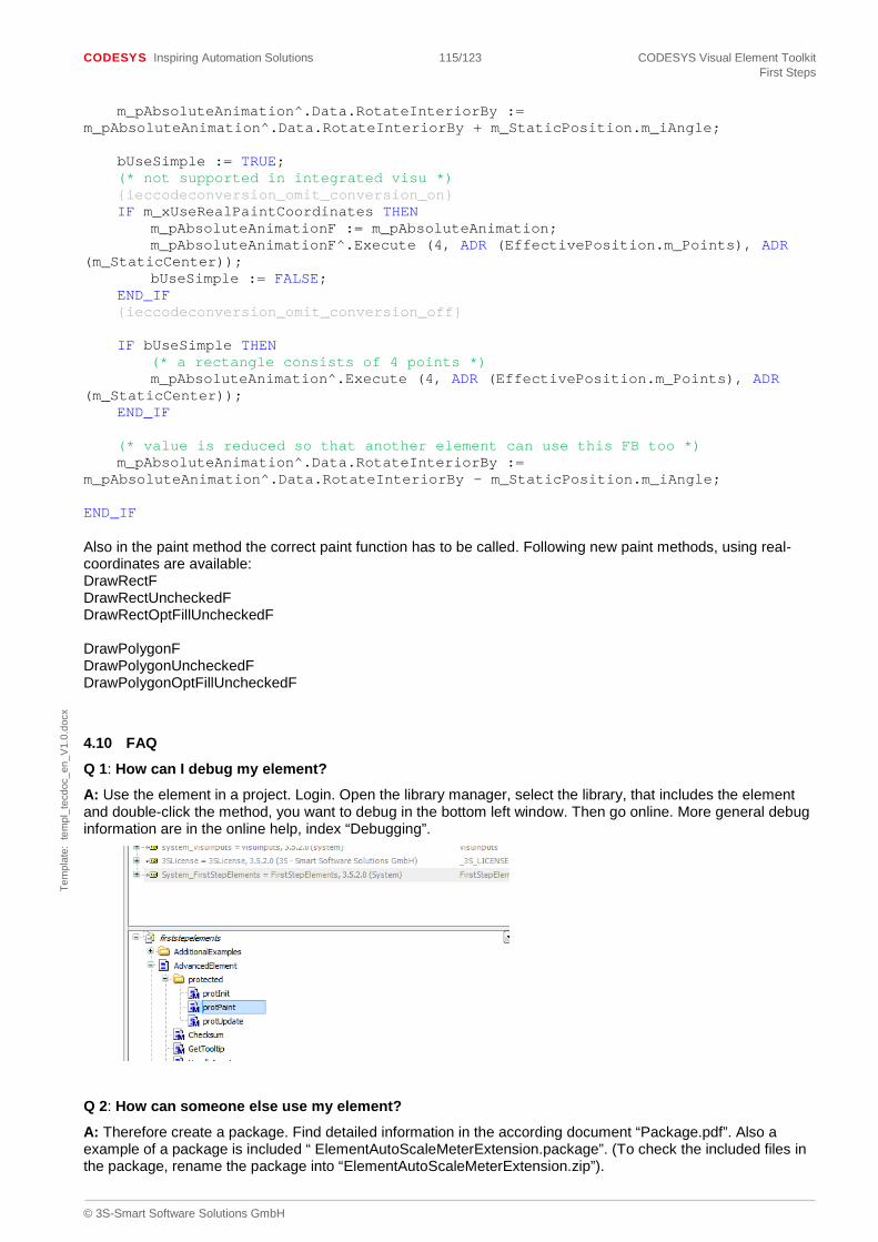
CODESYS Inspiring Automation Solutions 115/123 CODESYS Visual Element Toolkit First Steps
© 3S-Smart Software Solutions GmbH
Tem
plat
e: t
empl
_tec
doc_
en_V
1.0.
docx
m_pAbsoluteAnimation^.Data.RotateInteriorBy := m_pAbsoluteAnimation^.Data.RotateInteriorBy + m_StaticPosition.m_iAngle; bUseSimple := TRUE; (* not supported in integrated visu *) {ieccodeconversion_omit_conversion_on} IF m_xUseRealPaintCoordinates THEN m_pAbsoluteAnimationF := m_pAbsoluteAnimation; m_pAbsoluteAnimationF^.Execute (4, ADR (EffectivePosition.m_Points), ADR (m_StaticCenter)); bUseSimple := FALSE; END_IF {ieccodeconversion_omit_conversion_off} IF bUseSimple THEN (* a rectangle consists of 4 points *) m_pAbsoluteAnimation^.Execute (4, ADR (EffectivePosition.m_Points), ADR (m_StaticCenter)); END_IF (* value is reduced so that another element can use this FB too *) m_pAbsoluteAnimation^.Data.RotateInteriorBy := m_pAbsoluteAnimation^.Data.RotateInteriorBy – m_StaticPosition.m_iAngle; END_IF Also in the paint method the correct paint function has to be called. Following new paint methods, using real-coordinates are available: DrawRectF DrawRectUncheckedF DrawRectOptFillUncheckedF DrawPolygonF DrawPolygonUncheckedF DrawPolygonOptFillUncheckedF
4.10 FAQ
Q 1: How can I debug my element?
A: Use the element in a project. Login. Open the library manager, select the library, that includes the element and double-click the method, you want to debug in the bottom left window. Then go online. More general debug information are in the online help, index “Debugging”.
Q 2: How can someone else use my element?
A: Therefore create a package. Find detailed information in the according document “Package.pdf”. Also a example of a package is included “ ElementAutoScaleMeterExtension.package”. (To check the included files in the package, rename the package into “ElementAutoScaleMeterExtension.zip”).
CODESYS Inspiring Automation Solutions 116/123 CODESYS Visual Element Toolkit First Steps
© 3S-Smart Software Solutions GmbH
Tem
plat
e: t
empl
_tec
doc_
en_V
1.0.
docx
Content of the package that needs to change: - folder libraries: insert your library here. It is recommended to use the compiled library. In the included package, the source library is used, as you may be interested in the element. - folder VisualizationExtensions: insert your earlier on created extension. Take the files from where your visualization repository stored the extension. (check the “Visual Element Repository”- dialog for the location). - file package.manifest: the following parts need to be changed, according to your settings: Section <Strings>: <String Id=”GeneralName”> <Neutral>Visualization Extension AutoScaleMeter</Neutral> </String> This is the display name of the package, that is used in the package manager. Also change “GeneralCopyright” and “GeneralDescription”. Section <General>: create your own id. This can be done with the tool Guidgen.exe. Section <Components>: <Library> <Path>Libraries\VisuElemAutoScaleMeter.library</Path> </Library> Update the library name to your library name. <VisualizationExtension> <Repository>System</Repository> <Company>3S</Company> <Version>1.0.0.0</Version> <Name>Autoscaling Meter</Name> <Path>VisualizationExtensions\</Path> </VisualizationExtension>
It is important, to use the same company, version and extension-name as you have taken, when creating the extension! Important: Don’t use a space in your extension name. For the repository, take the company name, you have taken in the library-project information. This will look as follow: <VisualizationExtension> <Repository>MyCompany Name</Repository> <Company>MyCompany Name</Company> <Version>1.0.0.0</Version> <Name>MyExtension</Name> <Path>VisualizationExtensions\</Path> </VisualizationExtension>
After installing the package with the package manager, your element is available as visualization profile extension.
Q3: How can someone else use my style?
A: This is similar to question 2. Just put your style into the package. Also regard the images, used in the style. Find some more explanation about the entry for the package.manifest in the document ‘Package.pdf’ in chapter ‘VisualizationStyle Element ‘.
Q4: How can I use localized texts within my element?
A: See function VisuFctGetLocalizedString
Q5: How can I provide a localization for my element?
A: See 0 and 2.4.1
Q6: Why is an error “unknown type” pointing to the Visual Element Function_Block shown ?
A: Maybe your library has activated the setting “LanguageModelAttribute”. Please remove that attribute. For more information have a look at Create library.... Q7: What could be the reason for very strange error messages are shown during creation of my visualization extension?
A: Please check that the the used version of the Visual Element Toolkit matches your version of the programming sytem. Typically at least the service pack versions should be identically.

CODESYS Inspiring Automation Solutions 117/123 CODESYS Visual Element Toolkit First Steps
© 3S-Smart Software Solutions GmbH
Tem
plat
e: t
empl
_tec
doc_
en_V
1.0.
docx
Q8: Why are one or more attributes are not evaluated?
A: Please check the syntax of these attributes. It is important that the attribute name and the value are contained within apostrophes and not accent symbols. When doing copy/paste from documents, these might be wrong..

CODESYS Inspiring Automation Solutions 118/123 CODESYS Visual Element Toolkit New features
© 3S-Smart Software Solutions GmbH
Tem
plat
e: t
empl
_tec
doc_
en_V
1.0.
docx
5 New features
Please find below some information about new features. This can be additional functionality as well as change of existing behaviour.
New with CODESYS V3.5.14.0
• Adjustable radius of round rectangles: It is now possible (for recent clients) to draw round rectangles with an adjustable radius. This can be done by the new methods “DrawRectOptFillUnchecked2” etc. of “VisuFbRenderContext”. Please Remark: At the moment it is not possible to use different radiuses for x and y direction Please Remark: The according methods are not yet available using the interface for this functionblock (see CDS-63732)
• For the upcoming overlay feature (available only as preview in SP14) several new interfaces were introduced. As the feature is not finished and released yet, the according interfaces are not yet documented. Please Remark: Visualization elements built on base of this toolkit will probably not work correctly in this new mode without slight adjustments in their code. According implementation guidelines will be published with the final release of this features
New with CODESYS V3.5.13.0
• IVisualElement3
• Project information key “AllowVisuLibraryRedirection”
New with CODESYS V3.5.12.0
• Attribute 'ConstantWithOptionalExpression'
New with CODESYS V3.5.10.0
Project information key “LoadLibrariesEvenInIntegratedVisu”
New with CODESYS V3.5.9.0
Painting with element coordinates of type REAL. See the example.
New with CODESYS V3.5.7.0
• Attribute UseOnlyVarAccess to define, if an expression should be usable as variable-value or not. • New textflags for drawing text, see VisuEnumTextFlag • Attribute NotUsableInIntegratedVisu, for elements, that should not be used in the integrated visualization.
New with CODESYS V3.5.6.0
• Semi-transparent drawing: Now also the alpha-value of the color is considered. See also the attribute ShowTransparencyNode.
• Attribute RequiresValue :With this attribute, a compile-warning will be shown, if no value is configured for the variable in the visualization. For more information check the attribute explanation.
• Possibility of localization of texts within elements: See function VisuFctGetLocalizedString, and Localization
• New mechanism for onlinechanges affecting the visualization, please see chapter 2.8 for details.
New with CODESYS V3.5.5.2
Cyclical call of methods: an additional call to the Method “Update” could be done in some cycles before the call to “HandleInput”. For general information see Procedure.

CODESYS Inspiring Automation Solutions 119/123 CODESYS Visual Element Toolkit Change History
© 3S-Smart Software Solutions GmbH
Tem
plat
e: t
empl
_tec
doc_
en_V
1.0.
docx
Change History
Version Description Author Date
0.1 Created StS 03.04.2006
0.2 Added documentation requirements. Added TODOs FG 03.04.2008
0.4 Described attributes for code conversion FG 03.06.2009
0.5 continued, amended FG 11/2009
0.6 Described TODOs StS 02.03.2010
0.7 Review, ok FG 26.03.2010
1.0 Release MN 31.03.2010
1.0 English Version created acc. To German V1.0 MN 10.06.2010
1.1 New attribute ‘ieccodeconversion_only_reference’ for code conversion
FG 25.11.2010
1.2 New attribute ‘ieccodeconversion_fbinitparameter’ FG 01.12.2010
1.3 - Attributes for localization of visual elements described - Some minor bugfixes and changes regarding the categories
MP 02.12.2010
1.4 Optional attribute value for ‘ieccodeconversion_creategenericsetter’ and ‘ieccodeconversion_createarrayfactorymethod’ New attribute ‘ieccodeconversion_ignoreingettersetter’
FG 22.12.2010
1.5 Added Chapter 4: First Steps Added some examples to the attributes.
MS 06.07.2011
Added attribute ‘SetValueRange’ MS 11.07.2011
Added attribute ‘UseVariableForTextOutput’ MS 05.10.2011
1.6 Introduced chapter 2.5 MP 19.10.2011
1.7 New EditorType GradientColor, incl. attribute and struct MS 09.12.2011
1.8 Introduced section 0 MP 21.12.2011
Introduced section 2.6 MS 21.12.2011
1.9 Added DrawImage and DrawImageUnchecked MS 09.02.2012
Added DrawPie and DrawPieUnchecked MS 16.02.2012
1.10 Added all functionblock and method descriptions concerning the native control functionality
STS 16.03.2012
1.11 Added attributes regarding the online help and the description of properties
MP 28.03.2012
1.12 Added to FirstSteps chapter MS 23.04.2012
1.13 Added to FirstSteps chapter MS 11.06.2012
1.14 CDS-27205: VisuFbAnalyzeArrayVar MS 05.09.2012
1.15 Review, ok MS 12.10.2012
2.0 Release MaH 12.10.2012
2.1 Added attribute ‘ReferencedImageScaleType’ MP 29.11.2012
2.2 Added optional setting to attribute ‘VisibleIf’ MS 10.12.2012
2.3 Added explanation to Push / PopTransformation MS 08.01.2013

CODESYS Inspiring Automation Solutions 120/123 CODESYS Visual Element Toolkit Change History
© 3S-Smart Software Solutions GmbH
Tem
plat
e: t
empl
_tec
doc_
en_V
1.0.
docx
2.4 Review MS 08.01.2013
3.0 Release MaH 09.01.2013
3.1 Update of chapter First Steps, Added FAQ MS 18.01.2013
3.2 Rename of document MS 22.01.2013
3.3 Update of FAQ and Review MS 23.01.2013
4.0 Release MaH 23.01.2013
4.1 Added explanation of method checksum, VisuFbRectangularElement, Editortype IntValueRange, div. small changes
MS 19.02.2013
4.2 Working with basic visualization libraries, changed snippet. Update of SetTransformation
MS 20.02.2013
4.3 Div. small changes, Review MS 25.02.2013
5.0 Release MaH 25.02.2013
5.1 Added attribute ‘additionalcheck’ and ‘UserManagement’ MS 11.03.2013
5.2 Added setting to VisibleIf, div. small changes MS 01.07.2013
5.3 Added ‘Some helpful functions’, ‘ Implementation in VisuFbRectangularElement’, some FAQs and div. small changes
MS 04.07.2013
5.4 Review MS 04.07.2013
6.0 Release MaH 04.07.2013
6.1 Added: SetElementLookDeactive and GetElementLookDeactive MS 08.07.2013
6.2 Attribute SortFlag MS 12.07.2013
6.3 Clarified method protElementInfo MP 23.07.2013
6.4 Review MS 10.10.2013
7.0 Release MaH 10.10.2013
7.1 Added: VisuFbAnalyzeTwoDimensionalArray FG 18.10.2013
7.2 Changes in create a visual extension.. MS 29.10.2013
7.3 VisuFbAnalyzeTwoDimensionalArray.Checksum Minor adjustments
FG 31.10.2013
7.4 Review MS 05.11.2013
8.0 Release MaH 05.11.2013
8.1 Added restrictions for LanguageModelAttribute and VisuFbAnalyzeArrayVar
MS 09.12.2013
8.2 DrawImage MS 13.12.2013
8.3 VisuFbAnalyzeTwoDimensionalArray, hint to example MS 13.12.2013
8.4 4.8. new: Attached element instances FG 23.12.2013
8.5 GradientFill methods: DrawRectOptFillUnchecked, Polygon, Pie, Button
MS 03.01.2014
8.6 Added documentation for attribute ‘BitOffsetNode’ MP 10.01.2014
8.7 Added attribute animation in different chapters MS 16.01.2014
8.8 Modified attribute EditorType MS 22.01.2014
8.9 New attribute value for attribute ‘VisibleIf’ FG 24.01.2014
8.10 Removed wrong and obsolete references to the Java-Language MP 29.01.2014

CODESYS Inspiring Automation Solutions 121/123 CODESYS Visual Element Toolkit Change History
© 3S-Smart Software Solutions GmbH
Tem
plat
e: t
empl
_tec
doc_
en_V
1.0.
docx
8.11 VisuStructFont: Flags description MS 21.02.2014
8.12 Visu_StructElementInfo: 64-Bit Support MP 22.02.2014
8.13 Commented additional textflags MP 21.03.2014
8.14 Added to chapter helpful functions MS 28.04.2014
8.15 All examples are in one library, changed according texts MS 30.04.2014
8.16 Div. changes in chapter first steps MS 05.05.2014
8.17 Introduced section 2.7 with hints for multitouch support MP 16.05.2014
8.18 Review MS 16.05.2014
9.0 Release MaH 20.05.2014
9.1 Added attribute includewebvisualizationextensions for CDS-35444 MP 18.07.2014
9.2 Attribute ‘NumberOfLmGuids’ described. Modified: VisuFbAnalyzeTwoDimensionalArray
FG 25.07.2014
9.3 VisuFctGetLocalizedString described and added to FAQ FG 29.07.2014
9.4 Added attribute ShowTransparencyNode and color infos for CDS-17581
MS 12.08.2014
9.5 Attribute DisplayNameId, VisuFbAnalyzeBoolVar MS 28.08.2014
9.6 Attribute RequiresValue, PossibleRequiredValue, CDS-27153 MS 01.09.2014
9.7 Localization of visual extensions FG 02.09.2014
9.8 Attribute AnimationInitValue1, CDS-39363 MS 03.09.2014
9.9 Drag&Drop support, CDS-26357 FG 22.09.2014
9.10 VisuStructStaticTexts MS 24.09.2014
9.11 VisuFctRotatePoint MS 25.09.2014
9.12 Format time datatypes using Visu_FctHelpFormatTextOutput, CDS-38673
FG 10.10.2014
9.13 Hint that there might be an additional call to Update in 2.2 MP 15.10.2014
9.14 Chapter “New features” MS 20.10.2014
9.15 New condition “NotWithStyle” for attribute VisibleIf MS 23.10.2014
9.16 Initfromstyle: new type MS 29.10.2014
9.17 Hints to new onlinechange mechanism in chapter 2.8 MP 6.11.2014
9.18 Review MS 11.11.2014
10.0 Applying new template templ_tecdoc_en_V1.0.docx Release after formal review
MaH 12.11.2014
10.1 Attribute visucodeconversion_predefinedidentifiers, CDS-41244 FG 26.11.2014
10.2 FAQ MS 11.12.2014
10.3 Attribute PossibleOnlyVarAccess, UseOnlyVarAccess MS 21.01.2015
10.4 Attribute ImageId added. CDS-29456 StS 10.02.2015
10.4 New optional version constraint for attribute VisibleIf … NotWithStyle
FG 11.02.2015
10.5 Usage of checksum, initfromstyle MS 19.02.2015
10.6 VisuFbAnalyzeStringVar, CDS-42554 FG 11.03.2015
10.7 New textflag, CDS-3272 MS 12.03.2015
10.8 Attribute NotUsableInIntegratedVisu, CDS-41771 MS 16.03.2015

CODESYS Inspiring Automation Solutions 122/123 CODESYS Visual Element Toolkit Change History
© 3S-Smart Software Solutions GmbH
Tem
plat
e: t
empl
_tec
doc_
en_V
1.0.
docx
10.9 div. addition MS 11.05.2015
10.10 Review MS 11.05.2015
11.0 Release MaH 11.05.2015
11.1 New attributes DynamicEnumMemberVisibilityChecker and VisibleIf, CDS-42223
FG 30.06.2015
11.2 New attributes for fontdownload for framebuffervisu or targetvisulight, CDS-40344
MS 13.07.2015
11.3 Review MS 05.10.2015
12.0 Release MaH 05.10.2015
12.1 Added description for MeasureString and VisuFctGetMeasureStringResult
MS 08.12.2015
12.2 New String measuring functionality, CDS-44689 FG 08.01.2016
13.0 Release MaH 07.04.2016
13.1 New FB VisuFbMoveAbsoluteF, attributes and drawing methods MS 28.04.2016
13.2 Review MS 29.04.2016
14.0 Release MaH 29.04.2016
14.1 Added disclaimer MS 24.08.2016
14.2 Review MS 24.08.2016
15.0 Release MaH 24.08.2016
15.1 Extended attribute ExplicitOnlineHelpUrl, CDS-49288 MS 25.08.2016
15.2 New attribute ‘DataSource’ and new visibility condition ‘ValueOfNodeWithAttrExists’ for the new HMI, CDS-49781
MS/FG 25.08.2016
15.3 Setting LoadLibrariesEvenInIntegratedVisu in project information MS 25.08.2016
15.4 ValueOfNodeWithAttr supports also BOOL FG 23.09.2016
15.5 Updated Setting LoadLibrariesEvenInIntegratedVisu MS 14.10.2016
15.6 Review MS 19.10.2016
16.0 Release MaH 27.10.2016
16.1 Extended description of MultipleUsage MS 28.11.2016
16.2 Extended description of ImageId MS 29.11.2016
16.3 Added description of attribute conditionalshow, ClipRectangle, UnclipRectangle, PushClipRectangle and PopClipRectangle
MS 02.12.2016
16.4 Correct description of VisuFctGetMeasureString2Result (CDS-52650)
FG 21.12.2016
16.5 Updated Text Flag Constants MS 21.12.2016
16.6 Corrections according CDS-52344, Review MS 11.05.2017
17.0 Release MaH 15.05.2017
17.1 New attribute ElementLookLineWidth MS 16.01.2018
17.2 IVisualElement3 MS 15.02.2018
17.3 Updated after Changes in Implementation: removed attribute ‘ElementLookLineWidth’ and adjusted documentation of method GetCompleteSurroundingRect Added attribute ‘ConstantWithOptionalExpression’ Added FAQ 6-8 Sections new with 3.5.13 and 3.5.12 Fixed some typos
MP 13.06.2018

CODESYS Inspiring Automation Solutions 123/123 CODESYS Visual Element Toolkit Change History
© 3S-Smart Software Solutions GmbH
Tem
plat
e: t
empl
_tec
doc_
en_V
1.0.
docx
Review
18.0 Release MaH 13.06.2018
18.1 Added section “new with 3.5.14” MP 03.12.2018
18.2 Review section “new with 3.5.14” MPr 03.12.2018
18.3 Fixed Illustration 1.1, no specific Review necessary MP 03.12.2018
19.0 Release MaH 03.12.2018
Note: Not all CODESYS features are available in all territories. For more information on geographic restrictions, please contact [email protected].