Embed Size (px)
Citation preview

Cogging Torque Ripple Minimizationvia Position-Based Characterization
Matthew PiccoliSchool of Engineeringand Applied Science
University of PennsylvaniaPhiladelphia, Pennsylvania 19104–6391
Email: [email protected]
Mark YimSchool of Engineeringand Applied Science
University of PennsylvaniaPhiladelphia, Pennsylvania 19104–6391
Email: [email protected]
Abstract—Smooth motion is critical to some robotic applica-tions such as haptics or those requiring high precision forcecontrol. These systems are often direct-drive, so any torqueripple in the motor output must be minimal. Unfortunately, lowinherent torque ripple motors are expensive. Low cost brushlessDC motors are becoming more prevalent, especially from thehobby RC community. These motors often have the required hightorque density; however, they also have significant torque ripple.This paper presents a system that is low cost using a methodfor anticogging - the compensation of cogging torque in low cost,high torque motors. While other methods exist to compensate forcurrent-based torque ripple (mutual or reluctance torque), nonehave addressed cogging torque, except by adding expensive forcesensors. This paper presents two methods that use a positionsensor (already present for servo motors) to map cogging torqueto rotor position. The map is played back according to positionreported from the sensor to cancel the cogging torque. The designand testing of a low cost haptic arm using anticogging showsvalidation; however, the approach is much broader, and can beapplied to any precision force application. Test results on elevendifferent motors show an average removal of 69% of torqueripple with no added cost in robotic servo applications.
I. INTRODUCTION
Robots often employ low cost DC brushed motors whenperformance (speed, torque, and precision) is not a primaryconcern. When performance is a concern, permanent magnetsynchronous motors (PMSM) such as brushless DC motors(BLDCM) and brushless AC motors (BLACM), often workwell. PMSMs exhibit high torque to weight and inertia ra-tios. Compared to their AC induction counterparts, they aremore efficient and simpler to control. Unlike brushed motors,PMSMs do not require brushes to commute and can bemade more reliable and cheaper to manufacture. However, thecommutation cost and complexity is now pushed to externalcontrollers. Advancements in computation and miniaturizationin power electronics are outpacing advancements in electricmotors, so PMSMs are becoming even more attractive from acost standpoint.
Torque ripple is the periodic fluctuation in the motor torqueas the output shaft rotates. This has been recognized as aproblem in a variety of robot applications [1] [2] [3]. In hapticrendering it is especially troublesome [4]. Transmissions, suchas gear boxes, add non-linear torque variations that are diffi-cult to model and compensate, making direct-drive favorable.
0 20 40 60 80 100 120 1400
0.02
0.04
0.06
0.08
0.1
0.12
Price (USD)
TR
R (τ
pp/τ m
ax)
NominalAnticogged
Fig. 1: Nominal and compensated torque ripple ratio vs. price
PMSM’s high torque capability allow them to be used direct-drive and would be ideal if not for torque ripple.
The recent growth in the electric hobby RC market (inparticular flying vehicles) has provided a wide range of hightorque density, low cost motors. For example, the ExceedRC Rocket 86MA10 motor is 1/8th the price of a MaxonEC45 261501, is smaller and has higher maximum torque,but has a peak to peak torque ripple of 16 N mm, over 440 %that of the Maxon. When a motor spins at high speeds,torque ripple creates high frequency speed fluctuations thatgenerate sound and vibration. In haptic rendering, humans aresensitive to periodic motions especially higher frequencies,40 Hz to 100 Hz. With good compensation for the ripple, theseunwanted vibrations can be reduced, a quadrotor’s motorsmake less noise, robotic arms have smooth motion and haptictextures are rendered more accurately. At very low speeds,torque ripple can cause relatively large speed fluctuations, evencausing the motor to stop or move in discrete increments.In servo control, precise positioning is impossible with atraditional proportional or proportional-integral controller dueto the ripple’s nonlinearity.
Figure 1 shows a graph of a sampling of hobby RCbrushless motors measured by the authors along with somehigh performance ones (e.g. a Maxon EC 45, the right-most

data point). Torque ripple is shown in the figure as the torqueripple ratio (TRR, detailed in Equation 9). From this graph,one can see a correlation between lower priced motors andhigher TRR.
This paper presents an anticogging method to compensatefor cogging torque ripple that yields high performance frommotors that are a fraction of the cost of inherently low torqueripple motors. By enabling low cost yet high performancemotors, this work has the potential to transform the roboticsindustry by opening consumer markets for high performancerobots that are practical and low cost enough for a wide rangeof useful tasks in the home.
A. Types of Torque Ripple
There are four main types of torque ripple: mutual, reluc-tance, cogging, and friction.
Mutual torque is caused by the mutual interaction of therotor’s permanent magnets and the stator’s currents [5] [6].In a PMSM, this is the primary source of torque production,having the largest DC component 1. A mismatch of the rotor’smagnetic field and the stator’s current waveform causes dipsin the produced torque and contributes to torque ripple.
Reluctance torque is a result of variance in the stator’s self-inductance due to the rotor magnet saliency. The magnitudeof reluctance torque is a function of current [7]. In an idealBLACM (perfect sinusoidal back EMF and currents), reluc-tance torque does not exist or only contains a DC component.BLDCMs and non-ideal BLACMs contain reluctance torqueripple.
Cogging torque, also known as detent torque, comes fromthe rotor’s permanent magnets’ attraction to the salient por-tions of the stator [8]. It is not current-dependent and cannotbe detected by a current sensor. It also has no DC component,and thus only contributes to torque ripple.
Friction torque is not always axially symmetric, sincebearings within the motor may contain eccentricities. Thesetorque ripples are distinguishable from cogging torque by theironce per mechanical revolution frequency and change in signupon a change in direction.
BLACMs are intended to be driven off of AC mains,yielding a sinusoidal current waveform. BLDCMs are meantto be driven from a constant voltage source with a three phaseinverter in a simple 120 commutation, yielding a trapezoidalcurrent waveform. While the waveforms are similar enoughbetween BLACMs and BLDCMs to interchange waveforms,it is not recommended as increased mutual torque ripple andefficiency losses will result. On the other hand, an invertercan mimic sinusoidal or trapezoidal waveforms using 180
commutation and pulse width modulation (PWM). Using thismethod, virtually any waveform within the supply limits canbe generated, notably one that cancels all of the various typesof torque ripple [9].
1When referring to DC components or DC signals, the authors are referringto the non-oscillating offset components in the frequency domain, rather thancurrent.
B. Anticogging Background
Torque ripple minimization has been a topic of researchfor over 25 years. Many researchers have proposed finding anoptimal current waveform offline using various methods andusing a current controlled inverter to play back waveforms [5][6] [9] [10] [11]. However, [12] and [13] use current feedback,while Kim and Ha [14] use speed feedback at low speedsfor online estimation. In practice, speed control loops andestimation have limited success in minimizing torque ripple athigher speeds due to measurement delays.
Petrovic et al. [7] note that while cogging torque cannot bedetected from current measurements, all forms of torque rippleare seen via added mechanical sensors. While a few priorworks do mention the possibility of adding cogging torquesuppression to their current based algorithms [5] [10], noneexplore the specifics of finding the necessary waveform. Mostreduction methods leave the suppression of cogging torque tothe motor designers, typically by skewing the stator slots. Inplace of a speed loop, Qian et al. [8] use an external forcesensor as feedback to compensate for torque ripple at higherfrequencies. This method suppresses all forms of torque ripple,but the required sensor could cost more than the motor itself.
Despite the progress in the above solutions, torque rippleminimization is not yet widely used. Torque ripple mini-mization is either incomplete when using current sensingmethods or is prohibitively expensive when using an externaltorque sensor. However, as we will show, it is possibleto measure torque ripple via position or velocity feedbackwithout measuring torque directly. Observing speed changes(i.e. accelerations) and controlling speed to minimize ripplemay not work at high operational speeds, but monitoringspeed and its ripple at low nominal speeds is comparativelysimple. Data gathered at low speeds can be applied at highspeeds open loop with notable results. An alternative methodto monitoring speed ripple is to monitor position errors duringposition control. In the case of an unloaded motor duringposition control, cogging torque and friction are the onlytorque perturbations. Therefore, position error under positioncontrol can be used to map cogging torque and friction torque.
This work will use cogging torque waveforms that can beestimated either by mapping speed fluctuations with respectto position or by mapping position error with respect tocommanded position. Neither method requires more than anadded position sensor which is already required for servocontrol, and both methods can capture all forms of torqueripple. The methods work with voltage control or currentcontrol with little change. One of the methods can be appliedto sub-rotation intervals if the motor is constrained to certainpositions, as in servo control of a joint. The results can beadded to other algorithms to achieve complete torque ripplesuppression [5] [10].
The organization of this work is as follows. Section IIintroduces the assumptions, data collection, data analysis, andwaveform playback. Section III presents the experiments andtheir results. Section IV reviews these results. Finally, SectionV concludes.

Fig. 2: Diagram of a single half H-bridge inverter connectedto one of three phases of a sectioned motor.
II. ANTICOGGING PROPOSED APPROACH
If the torque ripple for a given state of the motor is known,a controller can suppress the ripple simply by commanding atorque that subtracts the ripple torque from the desired torque.Cogging torque is a function of position, so a map of coggingversus position must first be generated. The large number oftorque sources, combined with various non-linearities, makethe torque ripple map generation challenging. Generatingthis waveform map is the crux of torque ripple suppressionand can be estimated from a number of sources, includingcommanded position error and accelerations. These valuesmust be measured or converted to units that are useful to themotor driver, typically voltage or current.
A. AssumptionsThis paper makes the following assumptions:1) Mutual torque varies linearly with current.2) Each motor winding has equal resistance and inductance.3) A half-H bridge inverter is used to control each phase.4) The supply voltage and the inverter’s current rating are
high enough that the motor inductance does not preventthe creation of the desired waveform.
5) The PWM frequency, motor inductance, and motor in-ertia are all sufficiently high that the inverter switchingdoes not induce a torque ripple.
6) Cogging and friction torque ripples are time-invariant.7) The position sensor has a sufficiently high resolution.All math for current and voltage is done in signed scalar
values, as if the motor is brushed and the supply has positive,negative, and ground rails. Negative values are treated aspositive values with 180 added to the electrical position,θe. The conversion between electrical position and mechanicalposition, θm, is θe = pθm mod 2π where p is the number ofmagnetic pole pairs, as visualized in Figure 2. Control valuesneed to be converted from the desired input quadrature currentto phase currents and all feedback needs to be converted fromphase currents back to quadrature currents. With regards to thecontroller, the motor model can be represented by:
Vapp = θmKe + IR+ LdI
dt(1)
where Vapp is the voltage applied to the motor, Ke is theelectromotive force constant, I is the current, R is the motorresistance, and L is the motor inductance.
B. Waveform Collection
Two methods of collecting the torque ripple waveform wereexplored. Both exploit the fact that cogging torque is visiblefrom the mechanical state, i.e. position and speed of the rotor.Using standard position encoders to collect data maintains alow cost to the anticogged system.
Algorithm 1 Position Based Waveform Collection
for all i such that θm,min ≤ θm,cmd,i ≤ θm,max doCommand θm,cmd,iwhile θm 6= 0 do
Waitend whileθm,act,i ← θm,actdi ← dVsup,i ← VsupIi ← I
end for
1) Position Based: The position based collection of thecurrent or voltage waveform is done according to Algorithm 1and is outlined below. An ideal waveform is initially assumed,i.e. trapezoidal for a BLDCM or sinusoidal for a BLACM. Aproportional position controller with a high gain commandspositions:
θm,cmd,i ∀i ∈ N | θm,min ≤ θm,cmd,i ≤ θm,max (2)
with encoder positions, i, in monotonically increasing order.For a motor with continuous rotation, the minimum encoderposition, θm,min, equals θm,max, the maximum encoder po-sition, after a full rotation and i spans the full encoder countrange. At each commanded position i, measurements arerecorded including:
θm,act,i, di, Vsup,i, Ii
which are the actual position, applied PWM duty cycle in PerUnit (PU or %/100), supply voltage, and current, respectively.Upon each new command, the motor must come to a completestop and dI/dt = 0 before sampling data so that Equation 1can be simplified to Vapp = IR. When
θm,act,i = θm,act,j ∀i 6= j
lower magnitude values are discarded. The above process isrepeated commanding θm,cmd,i with i monotonically decreas-ing to find the waveform map in the reverse direction. Figure 3displays these waveforms taken from the experiments outlinedin Section III-A. Note the reverse is significantly different.
2) Acceleration Based: Algorithm 2 is used to collect thecurrent or voltage waveform based on motor accelerations. Asin the position based method, an ideal waveform is initiallyassumed. The motor begins at rest. The PWM duty cycle isincremented for each time step that the motor is stationary. The

0 50 100 150 200 250 300 350−0.2
−0.1
0
0.1
0.2
Position (degrees)
d (P
U)
ForwardReverseddt,st
(a) Full Rotation
2 4 6 8−0.2
−0.1
0
0.1
0.2
Position (degrees)
(b) Magnified
Fig. 3: Position method collected data from motor M4 in TableI described in Section III-A. (a) A full 360 dataset withforward and backward trials and (b) a magnified section.
lowest duty cycle that starts the motor and allows continuousrotation is ddt,st,cgmax
, and is the lowest duty cycle thatovercomes the largest cog, stiction, and deadtime (the period oftime in switching when no current flows, detailed in SectionII-C). The duty cycle is decremented until the motor stops,then incremented once to find the duty cycle, dmin, that runsthe motor at the minimum open loop speed. The motor isrestarted by commanding ddt,st,cgmax
for some amount oftime or number of revolutions, then dmin is commanded.The position sensor measures position, θm, and its derivativegives speed, θm, for each encoder location, m. Repeating thisprocess in the opposite direction yields similar results.
Algorithm 2 Acceleration Based Waveform Collection
ddt,st,cgmax← 0
while θm 6= 0 ∀θm,i doif θm = 0 then
ddt,st,cgmax← ddt,st,cgmax
+ min ∆dend ifCommand ddt,st,cgmax
end whiledmin ← ddt,st,cgmax
−min ∆dwhile θm 6= 0 do
Wait one revolutiondmin ← dmin −min ∆dCommand dmin
end whiledmin ← dmin + min ∆dCommand ddt,st,cgmax
WaitCommand dminWaitj ← 0while Rotations < n do
θm,j ← θmθm,j ← θmtj ← tj = j + 1
end while
C. Waveform Analysis
For cogging compensation, the data collected in Algorithms1 and 2 must be converted to voltage or current waveforms,Icg,i or Vcg,i. Fast Fourier Transforms (FFTs) and bi-cubicsplines have been used for fitting similar waveforms in orderto fill gaps in collected data since collection at every encoderposition is not guaranteed [15]. Unfortunately, the raw datacannot be directly fit. Two values, deadtime (explained below)and static friction (also called stiction), complicate matters.
Inverters used to generate waveforms can take one offour states at any given time: high-side transistor conducting,low-side transistor conducting, both conducting, and neitherconducting. It is undesirable for both to be conducting, as theinverter will have shoot-through current. Supply level voltagesare produced when only high or low are conducting, andutilizing PWM between the two an intermediate voltage canbe approximated. When neither conduct, the voltage floatsor current is sent through flyback diodes. This state is usedin 120 commutation on one phase at all times. Deadtime,ddt, is known as the short period when neither conduct whileswitching between low and high and vice versa so that it canbe guaranteed that both transistors never conduct at the sametime2. For accurate open-loop voltage control (via PWM) thecontroller must account for this deadtime so that the transistorshave the desired on-time pulse ratio. This can be accomplishedby adding ddt (in PU) to the commanded on-time PWM pulse,d (in PU). The effective applied voltage due to deadtime is:
Vapp =
Vsup ∗ (d− ddt) if d− ddt ≥ 0,
0 if d− ddt < 0.(3)
where Vsup is the DC supply voltage.If the deadtime is not already known and compensated
for by the driver, the data collected using the position basedmethod, Algorithm 1, is sufficient to determine ddt using Al-gorithm 3. All measured duplicates of θm,act are consolidatedby storing the maximum and minimum commanded duties andcurrents in dmax,i, dmin,i, Imax,i, and Imin,i respectively. Theaverages of these are the cogging waveforms, dcg,i and Icg,i.Half of the maximum difference of the duty cycle across themotor’s position range is the duty cycle required to overcomethe maximum deadtime and stiction, denoted ddt,stmax
. Allcommanded duty cycles with magnitudes below ddt,stmax
correspond to overcoming both stiction and deadtime andare averaged to get ddt,st. All commanded duty cycles withmagnitudes above ddt,st correspond to overcoming stictiononly. The mean of these duty cycles, dst,k, is subtracted fromddt,st to find the deadtime duty cycle, ddt. Likewise, thestiction current, denoted Ist, is the mean of half of the currentrange at each position.
Stiction manifests as a torque. In the open loop case it can becompensated for with a voltage, Vst, since at steady currents,voltage is linear with current, Ist, and thus is linear withtorque. However, because deadtime is a time, it is compensated
2Deadtime refers to only the time that neither transistor is conducting, andnot deadzone, the range of mechanical position slop.
by modifying the PWM duty cycle on-time by ddt, in bothcurrent and voltage control.
The effects of deadtime and stiction are shown in Figure 3b.The average ±ddt,st is shown as horizontal lines. Note that theduty cycles between those lines do not produce motion.
Once deadtime and stiction have been compensated, thevoltage or current waveforms can be extracted. When usingthe position method, Icg,i falls out from Algorithm 3 and Vcg,ican be found using dcg,i as d in Equation 3. When using theacceleration method, the accelerations are found by taking thetime derivative of the FFT fitted speeds, θm,i =
dθm,j
dtj. Noting
that the rotor inertia, J , is constant, the cogging torque is then:
τcg,i = Jθm,i (4)
The motor parameters can be used to find the mapping betweenτcg,i, Icg,i, and Vcg,i. Alternatively, ddt,st,cgmax
with Equation3 can be used to scale the acceleration waveform to find Vcg,i.
D. Waveform Suppression
For either current or voltage control, FFTs are fitted tothe data with respect to mechanical position as mentioned inSection II-C. The fits can be evaluated on the controller inruntime for low orders. Alternatively, a lookup table indexedby encoder position i, similar to Equation 2, stores precom-puted fitted values for Vcg,i or Icg,i. Stiction values could alsobe position dependent, but require more analysis to computethan in Algorithm 3. These values are added to the desiredvoltage or current, Vdes or Ides as indicated in the following:
Vout = Vdes + sgn(Vdes)Vst,i + Vcg,i (5)
d =VoutVsup
+ sgn(Vout)ddt (6)
orI = Ides + sgn(Ides)Ist,i + Icg,i (7)
The suppression of cogging torque involves varying current,I , which adds additional mutual and reluctance torque ripples.With the assumption that mutual and reluctance torques arelinear with current, and noting that the feedback throughoutthis process, θm, is a mechanical value and thus capturesall torque ripple sources, these additional torques are alreadycompensated for within the algorithm.
III. DESIGN AND EXPERIMENTAL RESULTS
To demonstrate the applicability of the proposed techniquefor robot arms, a two degree of freedom (DOF) planar robotarm was created that displays smooth motion suitable forsimple tool-mediated haptic rendering. A model for specifi-cations of this arm is the popular commercial haptic device,the PHANTOM Omni, now called the Geomagic Touch [16].The arm specifications includes a planar 2 DOF subset of theGeomatic Touch workspace. This workspace is advertised asrectangular area (160×120) mm. However, it is a polar devicewith workspace measurements between 100 mm < radius <270 mm and 90 in angler range. The maximum continuousforce output is 880 N mm.
Algorithm 3 Waveform Analysis
for all i such that θm,min ≤ θm,cmd,i ≤ θm,max dofor all j in range of θm,act,j do
if θm,cmd,i = θm,act,j thenif dj > dmax,i then
dmax,i ← djImax,i ← Ij
end ifif dj < dmin,i then
dmin,i ← djImin,i ← Ij
end ifend if
end forddt,st,i ← dmax,i−dmin,i
2
dcg,i ← dmax,i+dmin,i
2
Ist,i ← Imax,i−Imin,i
2
Icg,i ← Imax,i+Imin,i
2end forddt,stmax
= maxiddt,st,i
k ← 0for all i such that ddt,stmax
> dmax,i | −ddt,stmax< dmin,i
doddt,st,ktemp
← ddt,st,ik ← k + 1
end forddt,st = ddt,st,ktemp
k ← 0for all i such that ddt,stmax
< dmin,i | −ddt,stmax> dmax,i
dodst,k ← ddt,st,iVst,k ← ddt,st,iVsup,ik ← k + 1
end forVst ← dst,iV sup,iIst ← Ist,iddt ← ddt,st − dst,i
220mm163mm
Fig. 4: Top view of the robotic arm.

Figure 4 shows the two link serial chain used for finalvalidation. The length of the first link between the motors is220 mm and the second link between the second motor and theend effector is 163 mm with an effective envelope of 57 mm <radius < 383 mm, and 360 angular range which encompassesthe required (160×120) mm workspace. An onboard wirelessradio combined with a battery powering the second jointallows control of the second joint without wires crossing thefirst joint, reducing external friction sources. Encoders with12 bit resolution (4096 count) yield a translation positionalresolution of 0.087 mm with parallel links and 0.59 mm withperpendicular links, which is large compared to the 0.06 mmresolution of the Geomagic Touch, but is one sacrifice forobtaining a low cost yet larger workspace.
With the arm lengths chosen, the motor torque required togenerate desired max force can be determined. The translationforces applicable by the end effector depend on the jointangles. The nominal position is defined to be identical to theGeomagic Touch with the second joint at 90. The maximumapplicable force occurs with the shorter lever arm creating thelargest static force. This gives a target max motor torque of0.88 N · 163 mm = 143 N mm.
A. Experimental Setup
To determine the most suitable motor, various motors ofthe appropriate size were evaluated before and after anticog-ging was applied, but without robot arm links attached toensure the only sensed torque was from cogging torque.Experiments used a custom motor controller and driver. ATexas Instruments TMS320F28035 provides indirect field-oriented control at 100 kHz. A 600 W, 3 phase inverter, pulse-width modulated at 50 kHz symmetrically (up/down), enablesupdates at 100 kHz with a 300 count PWM. A diametricallyaligned magnet affixed to the rotor of each motor and anAustria Microsystems AS145B 12-bit (4096 count) magneticrotary encoder attached to the stator measure position. Thecost of this encoder and magnet pair is $6.69 USD at quantityof 1000 with similar solutions as low as $2.91 USD using theAS5115.
Although the PWM frequency of 50 kHz is excessive inposition control applications, this frequency is required forhigh speed rotation. The same setup can be used to spin motorsat over 22,000 RPM. At this speed an encoder count greaterthan 256 may be excessive. The combination high PWMfrequency and high encoder resolution allows for smoothcommutation from standstill to high speeds with a seamlesstransition and high fidelity waveform generation. The finalversion of the arm uses this setup, except an updated motordriver controls phase voltages at 10 kHz with a 1000 countPWM resolution.
For validating the proposed acceleration and position wave-form generation methods, a third method is used to provideground truth, experimentally determining torque ripple. Ituses an external torque sensor, sampled while performing theacceleration method. The motor’s datasheet values translatetorque to voltage and current for this third method.
Value Unit M1 M2 M3 M4 M5 M6R mΩ 1030 260 29 220 48 400Kv rpm/V 285 740 1400 710 1000 750I0 mA 183 550 1200 600 1700 600V0 V 24 10 10 10 8.4 10P Poles 16 14 14 14 14 14
Mass g 110 56 90 60 142 54τmax Nmm 77.7 90.3 239 134 363 127Cost USD 132 44.99 18 16 28 55Dia mm 42.8 28 37 28 38 28
Length mm 21.3 29 30 30 44 30τpp nom Nmm 3.6 5.5 26.3 16.0 38.4 8.7τpp pos Nmm 1.7 2.8 21.5 9.2 19.7 4.2τpp acc Nmm 1.7 3.9 5.3 5.4 12.0 3.0
Reduction % 53 49 80 66 69 65τres Nmm 0.54 0.83 3.9 1.02 3.3 0.53ddt PU .072 .082 .089 .082 .080 .090Vst mV 0 26.6 12.7 42.1 89.6 117
TABLE I: Motors and Results of Anticogging.M1 is a Maxon EC 45 251601.M2 is an E-flite Park 400 EFLM1300.M3 is an Exceed RC Rocket 86MB83.M4 is an Exceed RC Rocket 86MA10.M5 is a Turnigy Sk3542.M6 is an ElectriFly Rimfire GPMG4555.
The controller and driver are connected to eleven motors,six of which are indicated in Table I. The motors are fixedto an ATI Industrial Automation Nano17 six-axis force andtorque transducer with 1/64 N mm resolution. Values of θ, θ,Vsup, and d are read at 1 kHz by the controller, while torqueand current are read at 20 kHz in MATLAB.
B. Results
A common metric of torque ripple is the torque ripple factor(TRF) [9] [8]. The equation for TRF is:
TRF =τppτ0
(8)
where τpp is the peak to peak torque variation and τ0 isthe average applied torque. For mutual and reluctance torqueripple this measurement is constant over different commandedtorques, as both torque ripple and desired torque are linearwith current and thus τ0. Since cogging torque is independentof current and thus τ0, TRF is not constant and is less useful.TRF is infinite for all motors at zero applied torque, but thereis still torque ripple from cogging. In place of τ0, a divisorthat remains constant for each motor is proposed as TorqueRipple Ratio or TRR, defined as follows:
TRR =τppτmax
(9)
where τmax is the maximum continuous torque that the motorcan apply, which can be derived from the motor’s datasheet bymultiplying the maximum continuous current and the torqueconstant. Using this metric, Figure 1 shows the relationshipbetween torque ripple and price of 11 arbitrary BLDCMs; anotable inverse correlation before anticogging is evident, whileafter anticogging the metric is relatively constant.
Figure 5 shows a plot of the before and after results ofapplying anticogging to the 11 tested motors. A line fit shows

0 5 10 15 20 25 30 35 400
5
10
15
Nominal τpp (Nmm)
Ant
icog
ged
τ pp (
Nm
m)
Fig. 5: Torque ripple after anticogging versus torque ripplebefore anticogging for eleven tested motors. Fit line is y =0.3139x with an R2 = 0.8922.
0 50 100 150 200 250 300 350−0.01
−0.005
0
0.005
0.01
Position (degrees)
Tor
que
(Nm
)
PositionAccelerationSensor
Fig. 6: Fitted position, acceleration, and torque data versusposition on an Exceed RC 86MA10 motor. Voltages areconverted to torques using motor datasheet parameters.
a 69 % average reduction in torque ripple. Table I shows thedetails for a subset of the motors from Figure 5. τpp nom is thenominal peak to peak cogging torque of the motor. τpp pos andτpp acc are the peak to peak cogging torques after applyingthe position method and the acceleration method, respectively.
A metric that describes the value of a motor is τpp× cost.From the results in Table I, motor M2 has the best valuebefore compensation, but motor M4, a motor that fills thesame niche in terms of size, torque, and power, wins out aftercompensation. Conveniently, M4 is also the least expensive ofthe tested motors.
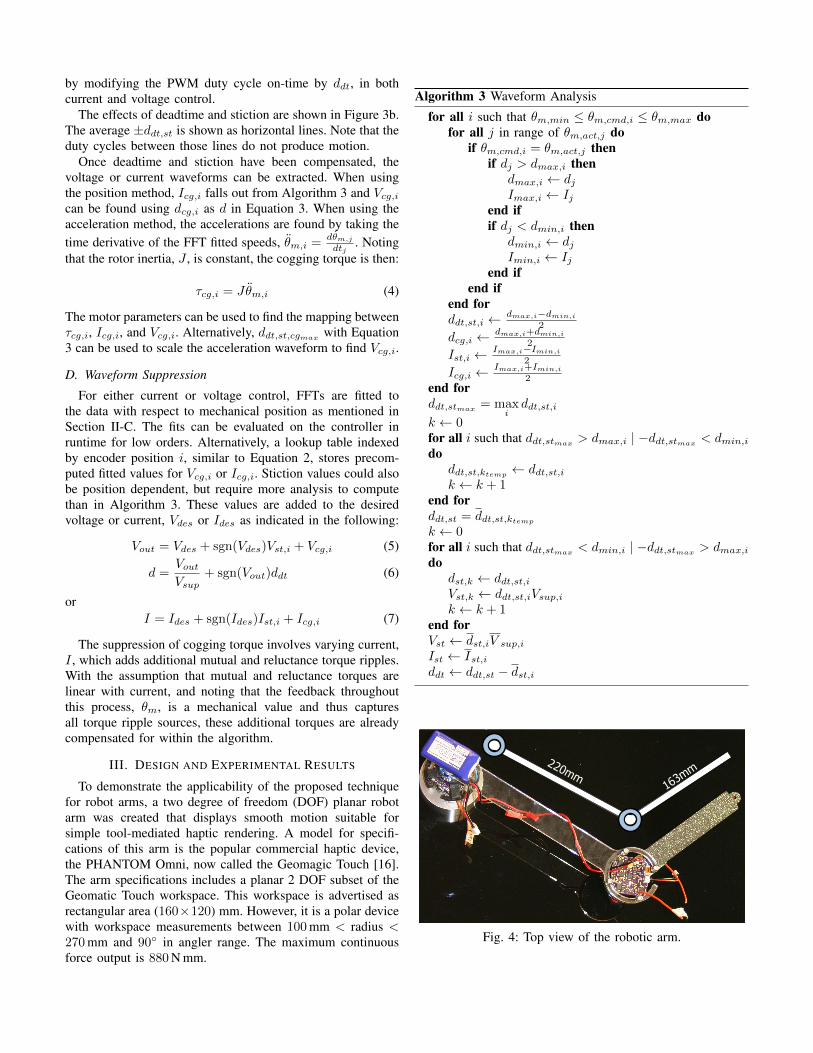
Haptic feedback is difficult to show in a visual form,so trajectory following was chosen instead to demonstratesmoothness. An example 2.035 m trajectory consisting of 36line segments as seen in Figure 7 represents a simplifiedexample of a path. Commands are sent and feedback isreceived synchronously at 150 Hz. Encoder positions are usedto calculate the end effector position. The effect of coggingon the end point position is clearly evident in the figure.The root mean squared position error (RMSE) with coggingcompensation turned off is 7.38 mm, while the RMSE withacceleration type anticogging on is 3.52 mm.
IV. DISCUSSION
A. Comparison of Methods
Verifying that both methods of cogging characterizationmap the torque ripple accurately is crucial. Figure 6 displaysboth methods as well as the ground truth from the externaltorque sensor. From the plot, the reader can see that allthree methods are in agreement in shape, while the positionmethod was slightly less accurate, as indicated in Table I. Allsuccessful characterizations have a RMS error of < 1 N mm.
It is mentioned in Section I-B that speed control loops havelimited success suppressing torque ripple, yet the accelerationmethod, which uses speed feedback, maps cogging torquewell. One reason is that the mapping is done offline at thelowest possible open loop speed, and thus sensor delay has lessimpact with respect to position. Furthermore, in a control loop,there must be error to correct and the reactions cause furtherdelays. Another factor may be that all motors tested weresmaller hobby or robotics motors in the 18 W to 670 W range.Small size yields smaller inertia as indicated by Equation 4,which gives larger, and thus more measurable accelerationsfor the same torque. The results may not be as favorable forhigher inertia motors, motors with higher minimum speeds, orlower frequency speed sensing.
The position method also tracked cogging torque well,despite being based on a different principle. Unlike theacceleration method, which loses DC signal3 values whentaking the derivative, the position method overcomes both theoscillating cogging torque and DC signal friction. Althoughconstant values are easily characterized and compensated, thecharacterization does introduce a failure mode. The extractedvalues for deadtime generally agree across motors, as seenin Table I. A supplementary test using a current sensor andthe torque sensor on motor M4 found that, while currentproduction starts at d = 0.071, external torque is not feltuntil d = 0.083. This indicates that the deadtime ddt = 0.071is the deadtime duty cycle for this motor driver and thestiction is dst = 0.012 or Vst = 60 mV at the tested location.The discrepancy between these values and those in Table Icould be because stiction is not consistent across the fullrange of motion, but the calculations for the compensationassume stiction is consistent. The expensive M1 motor has nodetectable stiction, perhaps contributing to its more accurateestimation of ddt = 0.072.
In the process of testing, it was found that with low gainson the position controller, deadtime was not visible in thedata. As always, proportional gains that are too high causethe controller to go unstable; thus, gains must be chosenwisely. Excessive gains occasionally prevented more than oneiteration of anticogging using the position method. Also, theposition method tends to predict higher torques, resulting inless iterations, but increased overcompensation when iterating.
With a sufficient quality waveform map loaded into thedriver’s onboard memory, the fidelity of the output wave-
3When referring to DC components or DC signals, the authors are referringto the non-oscillating offset components in the frequency domain, rather thancurrent.
form is dependent on the controller speed and resolution. Atthe maximum tested motor speeds (roughly 100 RPM), theencoder incremented around 7 kHz but the controller’s loopspeed was significantly higher at 100 kHz, indicating that theloop speed was not a factor. The PWM resolution during thesetests were 300 counts across a voltage of 5 V, resulting in0.01667 V increments. Converting this voltage increment intotorque increments for each motor using datasheet parameters,τ = KτI , and V = IR, gives the values indicated by τresin Table I. It can be seen that the resolutions are on thesame order of magnitude as the anticogged τpp, between 1and 5 counts across the full range. This indicates that PWMresolution is the limiting factor of torque ripple reduction inthis dataset. A supplementary test with a 600 count PWM,which is double previous tests, was performed on motor M5from Table I. The τpp is further reduced to 7.0 N mm, whichis a 42 % reduction from the lower resolution anticogging trialand an 82 % reduction from nominal, consistent with PWMas a leading factor in determining the amount of possiblereduction.
B. Arm Test Results
The results in the previous paragraph guided the designof the updated motor driver used in the robotic arm and isdescribed at the end of Section III. Despite the arm having sig-nificantly larger inertial loads, which raises the required outputtorque and lowers the TRF when compared with bare motorcog testing, RMSE decreased by 52 % using anticogging. Theresults are visualized in Figure 7.
Comparing the resulting motor capabilities to the desiredrobot arm requirements, the maximum continuous force isclose to the Geomagic Touch. The M4 has 134 N mm whichcompares to our target 143 N mm. While most commercialhaptic devices do not list torque ripple, they often specifya back-drive friction, which is an error from the desiredforce output. The Geomagic Touch lists a back drive fric-tion of 0.26 N. Solving Vst of motor M4, the stiction forceat the end of the second joint is 0.016 N. For a secondcomparison, we can normalize the back drive friction withthe max force, which gives an effective TRR = 0.30 forthe Geomagic Touch. This is quite large compared to theTRR of the proposed device at 0.04, however the TRR iscyclical and back drive is not. Human touch sensitivity isnoticeably stronger when frequencies >5 Hz [17]. Nominalhuman motions move the arm at 120 in 1 second, that wouldcorrespond to approximately 5 Hz as the dominant frequencyin Figure 6 over 120. Faster motions would result in higherfrequencies to which humans are much more sensitive.
V. CONCLUSION AND FUTURE WORK
A two DOF robot arm that has low-cost direct drive motorshas shown to be comparable to popular commercial devices.The commercial devices in comparison were six DOF socomparing against a subset of the device is not quite fair.However, the specifications of error (from back-drive), rangeof motion, and torque capability show that the arm can provideuseful forces and motions in haptic applications.
−200 −100 0 100 20050
100
150
200
mm
mm
CmdCogAnti
Fig. 7: Trajectory of robotic arm with and without anticogging.
Moreover, the arm was shown to have improved perfor-mance by using an anticogging control. The impact of thiswork is much broader than just haptic robot arms as the meth-ods have been tied more specifically to motor characteristicsthat would work on any robot arm.
Two methods for mapping the cogging torque waveformhave been presented. Both methods only require a positionsensor, yet both accurately map the cogging torque whencompared to an external force sensor. Reductions in torqueripple from 49 % to 80 % have been seen across the 11 testedmotors.
In many cases, cheap motors with comparable or better peaktorque and comparable or smaller size to high end motors canbe anticogged via the proposed methods such that the torqueripple is reduced below that of the more expensive motors.For example, M4 in Table I has slightly better mass and maxtorque, but has double the uncompensated torque ripple andis 30 % of the cost of the M6 motor. Using the accelerationcompensation method, the M4 τpp is reduced to 5.4 N mmwhich is significantly better than the M6 uncompensated τppof 8.7 N mm. Similar comparisons can be made with most ofthe other tested motors.
There are several ways to improve the performance of theproposed anticogging. Increasing PWM resolution is one ofthe most straightforward mechanisms. Decreasing the PWMfrequency will allow higher resolution at the cost of a lossof resolution at high speeds. Online waveform mapping andadjustment while performing arbitrary tasks might be usefulfor motor properties that vary over time, though it’s likelythese characteristics will change very slowly. Upon successfultorque ripple minimization, Hanselman [11] noted that the nextlogical step in motor design is to create motors with higherperforming back EMF shapes, since simplicity of commutationis no longer a concern due to improved power electronics andmicroprocessor computation.
As manufacturing structures and assembly become lowercost, actuators will dominate the cost of robotic systems.This is already the case in low-cost robotic systems. Findingmethods to use low-cost motors in high performance roboticapplications will enable new markets for robot systems.
Acknowledgements
The authors would like to acknowledge the support of NSFcontract number 1138847 and Willow Garage. We would alsolike to thank Matt Lisle, Kris Li, Patrik Roeller, Rui Zhang,Haofang Yuan, James Paulos, and Chris Thorne for their effortdeveloping hardware and performing tests.

REFERENCES
[1] G.J. Liu and A.A. Goldenberg. Robust control ofrobot manipulators incorporating motor dynamics. InIntelligent Robots and Systems’ 93, IROS’93. Proceed-ings of the 1993 IEEE/RSJ International Conference on,volume 1, pages 68–75. IEEE, 1993.
[2] W.S. Newman and J.J. Patel. Experiments in torque con-trol of the AdeptOne robot. In Robotics and Automation,1991. Proceedings., 1991 IEEE International Conferenceon, pages 1867–1872. IEEE, 1991.
[3] R.S. Wallace and D.G. Taylor. Low-torque-rippleswitched reluctance motors for direct-drive robotics.Robotics and Automation, IEEE Transactions on, 7(6):733–742, 1991.
[4] Vincent Hayward and Karon E. MacLean. Do It YourselfHaptics: Part I. IEEE Robotics and Automation Maga-zine, pages 88–104, December 2007.
[5] J.Y. Hung and Z. Ding. Design of currents to reducetorque ripple in brushless permanent magnet motors.Electric Power Applications, IEE Proceedings B, 140(4):260 –266, jul 1993. ISSN 0143-7038.
[6] S.J. Park, H.W. Park, M.H. Lee, and F. Harashima.A new approach for minimum-torque-ripple maximum-efficiency control of BLDC motor. Industrial Electronics,IEEE Transactions on, 47(1):109 –114, feb 2000. ISSN0278-0046. doi: 10.1109/41.824132.
[7] V. Petrovic, R. Ortega, A.M. Stankovic, and G. Tadmor.Design and implementation of an adaptive controller fortorque ripple minimization in PM synchronous motors.Power Electronics, IEEE Transactions on, 15(5):871 –880, sep 2000. ISSN 0885-8993. doi: 10.1109/63.867676.
[8] W. Qian, S.K. Panda, and J.X. Xu. Torque rippleminimization in PM synchronous motors using iterativelearning control. Power Electronics, IEEE Transactionson, 19(2):272 – 279, march 2004. ISSN 0885-8993. doi:10.1109/TPEL.2003.820537.
[9] H. Le-Huy, R. Perret, and R. Feuillet. Minimization ofTorque Ripple in Brushless DC Motor Drives. IndustryApplications, IEEE Transactions on, IA-22(4):748 –755,july 1986. ISSN 0093-9994. doi: 10.1109/TIA.1986.4504787.
[10] E. Favre, L. Cardoletti, and M. Jufer. Permanent-magnet synchronous motors: a comprehensive approachto cogging torque suppression. Industry Applications,IEEE Transactions on, 29(6):1141 –1149, nov/dec 1993.ISSN 0093-9994. doi: 10.1109/28.259725.
[11] D.C. Hanselman. Minimum torque ripple, maximumefficiency excitation of brushless permanent magnet mo-tors. Industrial Electronics, IEEE Transactions on,41(3):292 –300, jun 1994. ISSN 0278-0046. doi:10.1109/41.293899.
[12] J. Holtz and L. Springob. Identification and compensationof torque ripple in high-precision permanent magnetmotor drives. Industrial Electronics, IEEE Transactionson, 43(2):309 –320, apr 1996. ISSN 0278-0046. doi:
10.1109/41.491355.[13] Farhad Aghili. Adaptive Reshaping of Excitation Cur-
rents for Accurate Torque Control of Brushless Motors.Control Systems Technology, IEEE Transactions on, 16(2):356–364, March 2008. ISSN 1063-6536. doi:10.1109/TCST.2007.908213.
[14] Young-Hoon Kim and In-Joong Ha. A learning approachto precision speed control of servomotors and its appli-cation to a VCR. Control Systems Technology, IEEETransactions on, 7(4):466–477, Jul 1999. ISSN 1063-6536. doi: 10.1109/87.772162.
[15] J.C. Moreira. Torque ripple minimization in switchedreluctance motors via bi-cubic spline interpolation. InPower Electronics Specialists Conference, 1992. PESC’92 Record., 23rd Annual IEEE, pages 851 –856 vol.2,jun-3 jul 1992. doi: 10.1109/PESC.1992.254794.
[16] Geomagic. Geomagic Touch Specifications, January2014.
[17] Roland S. Johansson and J. Randall Flanagan. Codingand use of tactile signals from the fingertips in objectmanipulation tasks. Nature Reviews Neuroscience, 10:345–359, May 2009.


![Optimal Design for Cogging Torque Reduction of an …PD-A5-14]_804.pdf · Optimal Design for Cogging Torque Reduction of an IPMSM Using PSO with Anti-Submarine Operation Concept](https://img.pdfslide.net/doc/110x75/5b1557bd7f8b9ae7348be0ed/optimal-design-for-cogging-torque-reduction-of-an-pd-a5-14804pdf-optimal.jpg)