Embed Size (px)
Citation preview
Coherence Time Enhancement of Interacting Two-Level Systems in AluminumSuperconducting Resonators
Tamin Tai,1, ⇤ Jingnan Cai,1 and Steven M. Anlage1
1Quantum Materials Center, Department of Physics,
University of Maryland, College Park, MD 20742-4111, USA
(Dated: September 24, 2021)
Superconducting resonators are widely used in many applications such as qubit readout for quan-tum computing applications, and kinetic inductance detectors. These resonators are susceptible tonumerous loss and noise mechanisms under microwave excitation, especially the dissipation due tonon-equilibrium quasi-particles and two-level systems (TLS), which can result in a decrease of thesuperconducting intrinsic quality factor (Qi) in high quality superconducting resonators. Particu-larly in the few-photon and low temperature (T ) regime, TLS losses can become a dominant lossmechanism. In this study, novel aluminum half-wavelength resonators are investigated, focusing onthe loss properties at extra-low power and low temperature. An unusual increase of Qi(T ) withdeceasing temperature is observed. This behavior is attributed to the increase of TLS coherencetime (T2) at ultra-low temperatures and powers. This T2 increase is consistent with other work onresonant frequency noise in resonators and measurements of individual TLS, and likely arises frominteracting TLS in the aluminum half-wavelength resonators.
I. INTRODUCTION
Two-dimensional (2D) planar high internal quality fac-tor (Qi) superconducting resonators have been widelyfabricated and investigated in recent times for such ap-plication as single photon detectors,[1] kinetic inductancedetectors,[2] and quantum computing technology.[3] Re-cently, these high Qi resonators have been widely appliedin the design of large scale quantum gates, and tremen-dous progress has been made in terms of design, fab-rication and measurement techniques, which has led toorders of magnitude increase in coherence time and im-proved quantum fidelity [3–5]. In microwave measure-ments, although all qubits are operated at an excitationfrequency well below the superconducting gap energy, mi-crowave photons can be absorbed by quasiparticles, andthese quasiparticles interact with a phonon bath, creatingnon-equilibrium distributions of both quasiparticles andphonons. As a result, Cooper pair-breaking phonons canbe created.[6–9] This process contributes non-equilibriumquasiparticles, in addition to pair-breaking photons in-duced by cosmic rays,[10] higher order microwave har-monics, and the possibility of stray infrared radiation[11–13]. These non-equilibrium quasiparticles are a lim-iting factor on superconducting resonator Qi and qubitcoherence under any level of microwave excitation, andtheir presence results in a decrease of qubit relaxationtime (TQubit
1 ) and coherence time (TQubit2 ).[14]
Moreover, comparable losses due to two-level systems(TLS) almost universally occur [15–22] in the low powerregime in 2D superconducting resonators. It is widelybelieved that TLS are due to a fluctuating electric dipolethat couples to microwave electric fields. In general, TLScould originate from three kinds of interfaces on the de-
vices. One is the metal-vacuum interface due to surfaceoxide or contaminants. The other is the metal-dielectricsubstrate interface due to residual resist chemicals, andburied adsorbates. The third is the dielectric substrate-vacuum interface which could have hydroxide danglingbonds, processing residuals, and adsorbates.[23] To ad-dress these issues, di↵erent kinds of geometry of copla-nar waveguide (CPW) structure have been proposed andfabricated in the design of these resonant devices, withmore care given to the surface treatment to alleviate theTLS losses [24]. For example, a trenched structure in theCPW helps to mitigate the metal-dielectric TLS inter-action with the resonator fields.[25] These e↵orts haveimproved the 2D resonator intrinsic quality factor tomore than 1 million in recent realizations of high-Qi
resonators [25–28]. Nevertheless, TLS still exist evenin extra high Qi 3D superconducting radio frequencycavities used in particle accelerator applications.[29] Re-cently other sources of TLS loss have been proposedbased on quasiparticles trapped near the surface of asuperconductor.[30]Clearly TLS-based loss is a universal issue in supercon-
ducting resonators. The behavior of TLS under extra-low microwave power and low temperature still lacks fullelaboration due to the constraints of noise floor levelsin electronic equipment. Therefore, understanding thisTLS behavior especially in the low microwave excitationregime is essential, and would assist the superconductingquantum information community to mitigate its e↵ect onoperating quantum devices.We have designed a 2D half wavelength resonator with
a tapering geometry for the center line in a CPW struc-ture, where the linewidth varies from 50 µm down to 1µm. The reason for this design is to host many three-junction flux qubits in the center of the transmissionline resonator. This design can provide strong radio fre-quency coupling to the qubits to allow study of the col-lective behavior of quantum meta-materials. In this way,

2
153.71 nm
0.00 nm
10µm
128.72 nm
0.00 nm
10µm
153.71 nm
0 nm
128.72 nm0 nm
300 um 300 um
(a)
(b) (c)
(d)
(e)
Aluminum
Sapphire
ws
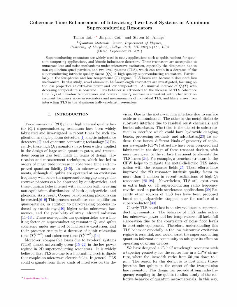
FIG. 1. An SEM image of the aluminum CPW resonator on sapphire substrate. (b) (c) Zoom-in SEM images of the left andright capacitive couplers. (d) AFM image highlighting the tapered center conductor with a 1 µm wide center trace near thecenter of the resonator, and (e) AFM topography image highlighting the 5 µm wide capacitive coupler from (b) or (c). Notethat the AFM probe scanning direction is 45 degrees with respect to the center-line direction to reduce AFM scanning artefacts.
qubits serve as artificial meta-atoms and are analogousto atomic cavity quantum electrodynamics, and couplingbetween neighboring artificial meta-atoms [31–35] alsocan be read out through the dispersive frequency shift ofthe cavity.[36–38] Theoretical publications discussing thephysics of qubit arrays coupled to the harmonic cavitiespredict a number of novel collective behaviors of thesemeta-atoms [39–41]. In this paper, we report our novelfinding on the TLS behavior in ultra-low power and lowtemperature through the design, fabrication, and char-acterization of this special geometry half-wavelength res-onator, without the qubits. The technique of ultra-lowpower microwave measurement with low noise to enhancethe signal-to-noise ratio (SNR) is critical for measuringthis TLS behavior.
II. EXPERIMENTAL METHODS
An aluminum (Al) half-wavelength (�/2) CPW res-onator on sapphire substrate was designed with a centerline width w = 50 µm and spacing s = 30 µm (the dis-tance between center conductor line and ground plane
as illustrated in Fig. 1(b) to maintain the characteristicimpedance near 50 ⌦ in the meander part. At the centerof the resonator a tapering structure narrows the centerline width down to w = 1 µm and spacing to s = 12 µm,which gradually increases the characteristic impedanceto 100 ⌦ at the resonator center. Fig. 1 (a) shows aperspective view of the resonator in a diced chip with adesigned fundamental frequency around 3.6 GHz. Theentire resonator is surrounded by many 10 µm by 10 µm
vortex moats. The resonator is symmetric and capaci-tively coupled through 5 µm capacitive gaps (1 (b) and1 (c)) in the center conductor. A topographic image ofthe narrowed resonator center section is shown in Fig. 1(d) with a critical dimension around w = 1 µm in width.
This CPW resonator was fabricated using standardphoto-lithography technology procedures. In detail, firsta 100 nm thick Al film was deposited on a 3-inch diame-ter sapphire wafer using thermal evaporation technologywith a background pressure of ⇠ 3 ⇥ 10�7 mbar. Thena thin SHIPLEY1813 photo-resist was coated on top ofthe film and exposed to UV through the designed pho-tomask. The UV exposed wafer was developed and thenwet etched by commercial Transene Aluminum Etchant.

3
(a) (b)
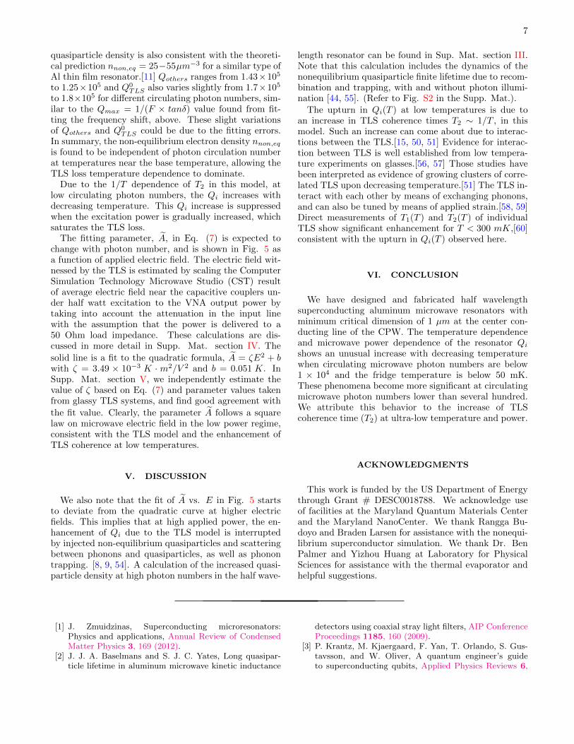
FIG. 2. (a) Temperature dependent first harmonic resonant frequency f0 of the �/2 Aluminum co-planar waveguide resonatormeasured at di↵erent average photon numbers. (b) Average photon number dependence of the intrinsic quality factor, Qi atits first harmonic frequency measured at di↵erent fridge temperatures.
The remaining photoresist was stripped o↵ by acetoneand the entire wafer was cleaned by methanol and iso-propanol. Finally, the wafer was coated in a protectivephoto-resist and then diced into many chips. After dic-ing, the protective photo-resist was removed and the chipwas mounted on a printed circuit board bolted inside acopper box. Several lumps of indium were pressed be-tween the on-chip ground planes and the copper boxground to achieve a continuous ground contact, whichmitigates parasitic resonant microwave modes due to un-even electrical grounding. The indium lumps also securedthe chip in the center of the printed circuit board. Theon-chip transmission line is wire-bonded to the centerconductor of the transmission line on the printed circuitboard by gold wires. Finally, the copper box is cappedby a copper lid to eliminate stray light illumination.
The device was placed in a closed Cryoperm cylinderin a BlueFors (BF-XLD 400) croygen-free dilution refrig-erator (base temperature 10 mK) to minimize any strayDC magnetic field, and the shield was thermally anchoredto the mixing chamber plate. The microwave excitationwas attenuated by 66 dB in the input line through aseries of attenuators at di↵erent cooling stages in the di-lution fridge before going into the resonator. The trans-mitted signal was amplified through a cryogenic ampli-fier with 36 dB gain and then boosted by another 37dB at ambient temperature before the transmitted sig-nal (S21) was measured by a Keysight N5242A vectornetwork analyzer (VNA). The ultra-low power measure-ments were performed using the smallest intermediatefrequency bandwidth (1 Hz) of the VNA, with a 400 kHzspan across the resonance, following 5 averages to reducethe random noise. Further details of the experimentalsetup for the high SNR measurement at ultra-low mi-crowave power can be found in section I of the Supple-mental Material.
III. EXPERIMENTAL DATA
The measured transmitted signal (S21(f)) has a fun-damental (�/2) resonance peak around f = 3.644 GHzat the fridge base temperature when sweeping the fre-quency, f , (or ! = 2⇡f). The complex S21(f) signalis fit to an equivalent circuit model of a two-port res-onator capacitively coupled to external microwave exci-tation [9, 42].
S21(f) = |S21,in||S21,out|
QL/Qc
1 + 2jQL(ff0
� 1)ej�
!
+C0 (1)
where |S21,in| is the attenuation loss in the transmissionof the input line, |S21,out| is the gain in the transmissionof the output line, QL is the loaded quality factor, Qc isthe coupling quality factor representing the dissipationto the external circuit, j =
p�1, f0 is the resonance
frequency of the half-wavelength (�/2) CPW resonator,� is the phase and C0 is an o↵set in the complex S21 planedue to background contributions.[42] The internal qualityfactor, Qi, representing internal dissipation is extractedfrom the identity 1/QL ⌘ 1/Qi + 1/Qc. The averagenumber of circulating microwave photons in the cavitycan be estimated using the approximation [9, 43] < n >=2Q2
LPin
Qc~!20
in two ports measurement where Pin is the input
power to the resonator after the attenuation in the inputline, ~ is the reduced Planck constant and !0 = 2⇡f0 isthe angular frequency of the resonance.Figure 2(a) shows the temperature dependence of
the resonant frequency, f0, for di↵erent circulating mi-crowave photon numbers inside the CPW resonator, byfitting each resonance circle in the complex S21 planeto Eq. 1. For each case, the maximum resonance fre-quency occurs at the 10 mK fridge base temperature andthen shows a local maximum around 200 mK. This phe-

4
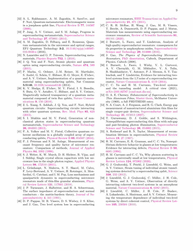
FIG. 3. Temperature dependent fundamental (�/2) mode resonant frequency f0(T ) of the Al CPW resonator at an externalmicrowave excitation creating ⇠ 10 circulating photons. The inset highlights the low temperature regime which the frequencyshift is dominated by the TLS mechanism. The dots are experimental data and solid line is the model fit.
nomenon seems to be independent of the average cir-culating photon number. When the fridge temperatureis higher than 200 mK, the resonance frequency quicklydecreases with increasing temperature due to the largeinjection of thermal quasiparticles, which results in asurface impedance increase in the superconducting res-onator. The dependence of internal quality factor Qi
on the average circulating photon number at di↵erentrepresentative fridge temperatures is shown in Fig. 2(b). For each curve, the Qi gradually increases with in-creased circulating photon numbers, but then the Qi issuddenly suppressed at extremely high photon numbers(< n >⇠ 108). One important observation is that in thelow photon number regime, one can see the Qi at T =12 mK is higher than the Qi at T = 80 mK and T = 120mK. This unusual behavior will be discussed in the nextsection.
IV. MODELING
Researchers working on the loss mechanisms of su-perconducting resonators have primarily attributed thepower and temperature dependent frequency shifts andQi variations at low temperatures to the non-equilibriumquasiparticles in the superconducting metals and TLSin the dielectrics. However, it can be di�cult to ex-perimentally distinguish the TLS-loss mechanism fromnon-equilibrium quasiparticle-related loss, since both lossmechanisms are power and temperature dependent in thesame operational regime for many superconducting de-vices, including resonators and qubits.[14] Here, we willinterpret our data in terms of two main features, namelythe electrodynamics of TLS in the dielectrics combinedwith that of both equilibrium and non-equilibrium quasi-particles in the metals. To interpret the local maximum
of resonance frequency at 200 mK in Fig. 2, an ana-lytical equation combining the TLS model and thermalquasiparticle model is used to fit the curve,[19, 24, 44]
f(T )� fn
fn= F
tan�
⇡
✓Re
(
1
2+
~!2⇡jkBT
)
�� log(
~!2⇡kBT
)
◆
�↵
2
r⇡�S0
2kBTexp(
��S0
kBT)(2)
where F is the filling factor defined as the fraction ofthe resonator total electrical energy stored in the TLSmaterial,[17] fn is the resonance frequency in the limitof low temperature and microwave power, (·) is thecomplex digamma function, tan� is the loss tangent ofthe dielectric material, kB is the Boltzmann constant, Tis temperature, ↵ = Lkinetic/Ltotal is the kinetic induc-tance fraction of the CPW resonator, and �S0 is the alu-minum superconducting gap at zero temperature. Thefirst term in Eq. 2 represents the frequency shift cre-ated by the TLS mechanism [17] and the second termis the frequency shift due to equilibrium quasiparticlesusing the Bardeen-Cooper-Schrie↵er (BCS) model [44][45]. (We show in the Sup. Mat. section III that thenon-equilibrium depairing is temperature independent inthis range, hence we can ignore this contribution.)The fit to the frequency shift data is shown in Fig.
3, and the extracted fitting parameters indicate that thealuminum superconducting gap at zero temperature is�S0 =174.03 µeV , a value close to the BCS gap ap-proximation which is 1.76kBTc with transition temper-ature Tc = 1.15 K. The values of the other fitting pa-rameters are ↵ = 0.0185, fn = 3.64422 ⇥ 109 Hz andF ⇥ tan� = 6.4⇥ 10�6. The value of F ⇥ tan� is consis-tent with other results on a variety of superconductingresonators.[17, 21]. Note that this fit predicts the maxi-

5
0.0E+00
2.0E+04
4.0E+04
6.0E+04
8.0E+04
1.0E+05
1.2E+05
0 0.1 0.2 0.3 0.4 0.5 0.6
Qi
Temperature (K)
<n>= 1<n>=5<n>=80<n>=1E3<n>=1E4<n>= 1E5
FIG. 4. Temperature dependent internal quality factor Qi at di↵erent circulating photon numbers. The dots are experimentaldata points, and the lines (solid or dashed) are the fitting curves from the model described in the text.
mum Qmax = (F ⇥ tan�)�1 = 1.56⇥105 at low tempera-ture and low power, 23 % larger than what is observed inFig. 4. However, this is consistent with previous observa-tions that attribute the di↵erence between predicted andmeasuredQ-factors to the di↵erence in bandwidth of TLSstates contributing to Q and to frequency shift.[24, 46]Note that similar frequency shift behavior at low tem-perature was also found at higher circulating microwavephoton numbers up to 108.
The temperature dependence of internal quality factorQi(T ) is shown in Fig. 4 at di↵erent circulating pho-ton numbers inside the resonator cavity. At high photonnumbers, Qi(T ) presents the highest value at the fridgebase temperature, presumably due to saturation of TLS,and then maintains the high Qi up to T= 200 mK. Thedramatic decrease of Qi for temperatures above 200 mKis due to an increase in equilibrium thermal quasiparticlesand this is a well-known phenomenon of superconductingresonators. One sees a di↵erent temperature dependenceof Qi(T ) in the low circulating photon number regimeand at low temperatures. Clearly, below 103 circulatingphotons, Qi(T ) is maximum at the fridge base tempera-ture (⇠ 10 mK) then slightly drops to a local minimumaround T =50 mK. From 50 mK to 200 mK, Qi(T ) grad-ually increases with increasing fridge temperature. Theconventional explanation is that the thermal energy sat-urates the TLS leading to decreasing losses.[47] However,the observed Qi(T ) increase with decreasing temperaturefrom 50 mK to 10 mK has not been explicitly acknowl-edged and discussed in prior work, to our knowledge.Indications of an upturn in Qi(T ) has been attributed topoor SNR and therefore this behavior has been treatedas not statistically significant.[47, 48] To interpret thisunusual Qi(T ) increase in our aluminum resonators at
low power and low temperature, an extended TLS modelis applied here.A general TLS Hamiltonian can be written as HTLS =
12
✓�� �0
�0 �
◆where � is the asymmetry of the double
well potential and �0 is the tunneling barrier energy be-tween two potential wells.[9, 15] In addition, one shouldalso expect there are many TLSs with di↵erent values of� and �0, therefore in the standard model of TLS loss, auniform distribution in � and log uniform distribution in�0 is assumed.[15] When the two-level population is inthermal equilibrium, for which the phonon emission andelectromagnetic absorption processes are balanced, thelongitudinal relaxation time (T1) of the assembled TLSis given by [49]
1
T1= (
�0
")2�2L
v5L
+�2T
v5T
�"3
2⇡⇢~4 coth
✓"
2kBT
◆(3)
where " =p�2 +�2
0 is the di↵erence of the two eigen-values ofHTLS , �L and �T are the longitudinal and trans-verse deformation potentials, respectively, vL and vT arethe longitudinal and transverse sound velocities, respec-tively, and ⇢ is the mass density. In addition, the coher-ence time (T2) of the interacting TLS [50] is described as[15, 49]
1
T2⇠ C
2�2P0kBT
⇡~⇢v2�
"(4)
Note that C is dimensionless phonon scattering rate,[51]and is often taken to be a constant of order unity, P0kBT
is the volume density of thermally excited TLS with P0
(two-level density of states) on the order of 1044J�1 ⇥

6
FIG. 5. Applied electric field dependence of the fitting parameter eA used to fit the Qi vs. temperature data at di↵erentcirculating photon numbers. The dots are the extracted values from the fitting model, and the solid line is a fit to a quadraticformula with coe�cient ⇣ = 3.49⇥ 10�3 K ⇤m2/V 2 and b = 0.051K. The inset shows the same values plotted in a horizontallog scale to cover the higher electric field regime.
m�3 , v is the averaged sound velocity, and ��/" is the
elastic dipole moment. From this result, one can expectT2 has a 1/T dependence on temperature, which arisesfrom the TLS interaction bandwidth scaling with thermalenergy kBT .[15]
The imaginary part of the relative dielectric constantis regarded as the TLS loss tangent [49]
�TLS = ✏00TLS(!)/✏TLS =
�0TLS tanh
⇣"
2kBT
⌘
p1 + ⌦2T1T2
(5)
with Rabi frequency ⌦ [49]
⌦ =2d0�0p
3~"| ~E| (6)
where d0 is the maximum transition electric dipole mo-ment of a TLS and ~E is the microwave electric field. Byexpressing T1, T2 and ⌦ with Eqs. (3), (4), and (6), thequality factor due to the TLS loss can be written as,
1
QTLS=
1
Q0TLS
tanh⇣
"2kBT
⌘
r1 +
eAT tanh
⇣"
2kBT
⌘
with eA =
4d203"2
�2L
v5L
+�2T
v5T
��1⇡2⇢2~3v2
C�2P0kB�
!E
2 (7)
Here, the intrinsic loss tangent of the TLS is �0TLS =
1/Q0TLS . Because eA is proportional to the square of the
electric field E witnessed by the TLS, one can simplywrite eA = ⇣ ⇥E
2 and ⇣ is a constant which is composedof d0, ⇢, v, �, P0, C, and �, all of which are assumed to beelectric field independent terms.
In addition to the QTLS contribution to Qi, the lossesdue to quasiparticles with density nqp, including both
non-equilibrium (nnon,eq) and equilibrium quasiparticles,should also be taken into consideration:
nqp = nnon,eq + 2N0
p2⇡kBT�S0 Exp
✓��S0
kBT
◆(8)
(valid for T ⌧ Tc) where N0 = 1047 J�1
m�3 (equivalent
to 1.74⇥ 104 µeV�1
µm�3 [7][13] ) is the single spin den-
sity of states at the Fermi level, and hence Qqp / 1nqp
,
where nqp remains finite as T ! 0. In addition, there aresome temperature independent loss mechanisms includ-ing moving vortices arising from stray magnetic field andgeometry dependent microwave radiation loss, etc. Theidentity 1
Qothers= 1
Qvortices+ 1
Qradcan be used to sum-
marize these temperature independent loss mechanisms.Therefore, one can say the internal quality factor of
this half wavelength resonator follows the following ex-pression in the limit T ⌧ Tc:
1
Qi=
1
QTLS(T,E)+
1
QQP (T,E)+
1
Qothers(9)
In Fig. 4, the solid and dashed lines are generatedby fitting the Qi(T ) to the model described above. Thequantities nnon,eq, �S0, eA, Q0
TLS , Qqp(0K), and Qothers
are treated as fitting parameters. In addition, we take"=~!0 for fitting the Qi(T ). The fits give (see TableSI in Sup. Mat. section II) �S0 = 185 ⇠ 188 µeV , agap value slightly larger than the value obtained fromthe frequency shift model above, due to the inclusionof non-equilibrium quasiparticles. This gap value is inagreement with many published experimental results ofAl thin films [52, 53]. Also, nnon,eq ⇠ 50 µm
�3, avalue which can be explained by theoretical treatmentof the non-equilibrium distribution of quasiparticles andphonons in a superconductor driven by a continuous mi-crowave photon flux [6, 9, 11] based on our half wave-length CPW Al resonator geometry and experimentalconditions (see supplemental material section III). This
7
quasiparticle density is also consistent with the theoreti-cal prediction nnon,eq = 25�55µm�3 for a similar type ofAl thin film resonator.[11] Qothers ranges from 1.43⇥105
to 1.25⇥105 and Q0TLS also varies slightly from 1.7⇥105
to 1.8⇥105 for di↵erent circulating photon numbers, sim-ilar to the Qmax = 1/(F ⇥ tan�) value found from fit-ting the frequency shift, above. These slight variationsof Qothers and Q
0TLS could be due to the fitting errors.
In summary, the non-equilibrium electron density nnon,eq
is found to be independent of photon circulation numberat temperatures near the base temperature, allowing theTLS loss temperature dependence to dominate.
Due to the 1/T dependence of T2 in this model, atlow circulating photon numbers, the Qi increases withdecreasing temperature. This Qi increase is suppressedwhen the excitation power is gradually increased, whichsaturates the TLS loss.
The fitting parameter, eA, in Eq. (7) is expected tochange with photon number, and is shown in Fig. 5 asa function of applied electric field. The electric field wit-nessed by the TLS is estimated by scaling the ComputerSimulation Technology Microwave Studio (CST) resultof average electric field near the capacitive couplers un-der half watt excitation to the VNA output power bytaking into account the attenuation in the input linewith the assumption that the power is delivered to a50 Ohm load impedance. These calculations are dis-cussed in more detail in Supp. Mat. section IV. Thesolid line is a fit to the quadratic formula, eA = ⇣E
2 + b
with ⇣ = 3.49 ⇥ 10�3K · m2
/V2 and b = 0.051 K. In
Supp. Mat. section V, we independently estimate thevalue of ⇣ based on Eq. (7) and parameter values takenfrom glassy TLS systems, and find good agreement withthe fit value. Clearly, the parameter eA follows a squarelaw on microwave electric field in the low power regime,consistent with the TLS model and the enhancement ofTLS coherence at low temperatures.
V. DISCUSSION
We also note that the fit of eA vs. E in Fig. 5 startsto deviate from the quadratic curve at higher electricfields. This implies that at high applied power, the en-hancement of Qi due to the TLS model is interruptedby injected non-equilibrium quasiparticles and scatteringbetween phonons and quasiparticles, as well as phonontrapping. [8, 9, 54]. A calculation of the increased quasi-particle density at high photon numbers in the half wave-
length resonator can be found in Sup. Mat. section III.Note that this calculation includes the dynamics of thenonequilibrium quasiparticle finite lifetime due to recom-bination and trapping, with and without photon illumi-nation [44, 55]. (Refer to Fig. S2 in the Supp. Mat.).The upturn in Qi(T ) at low temperatures is due to
an increase in TLS coherence times T2 ⇠ 1/T , in thismodel. Such an increase can come about due to interac-tions between the TLS.[15, 50, 51] Evidence for interac-tion between TLS is well established from low tempera-ture experiments on glasses.[56, 57] Those studies havebeen interpreted as evidence of growing clusters of corre-lated TLS upon decreasing temperature.[51] The TLS in-teract with each other by means of exchanging phonons,and can also be tuned by means of applied strain.[58, 59]Direct measurements of T1(T ) and T2(T ) of individualTLS show significant enhancement for T < 300 mK,[60]consistent with the upturn in Qi(T ) observed here.
VI. CONCLUSION
We have designed and fabricated half wavelengthsuperconducting aluminum microwave resonators withminimum critical dimension of 1 µm at the center con-ducting line of the CPW. The temperature dependenceand microwave power dependence of the resonator Qi
shows an unusual increase with decreasing temperaturewhen circulating microwave photon numbers are below1 ⇥ 104 and the fridge temperature is below 50 mK.These phenomena become more significant at circulatingmicrowave photon numbers lower than several hundred.We attribute this behavior to the increase of TLScoherence time (T2) at ultra-low temperature and power.
ACKNOWLEDGMENTS
This work is funded by the US Department of Energythrough Grant # DESC0018788. We acknowledge useof facilities at the Maryland Quantum Materials Centerand the Maryland NanoCenter. We thank Rangga Bu-doyo and Braden Larsen for assistance with the nonequi-librium superconductor simulation. We thank Dr. BenPalmer and Yizhou Huang at Laboratory for PhysicalSciences for assistance with the thermal evaporator andhelpful suggestions.
[1] J. Zmuidzinas, Superconducting microresonators:Physics and applications, Annual Review of CondensedMatter Physics 3, 169 (2012).
[2] J. J. A. Baselmans and S. J. C. Yates, Long quasipar-ticle lifetime in aluminum microwave kinetic inductance
detectors using coaxial stray light filters, AIP ConferenceProceedings 1185, 160 (2009).
[3] P. Krantz, M. Kjaergaard, F. Yan, T. Orlando, S. Gus-tavsson, and W. Oliver, A quantum engineer’s guideto superconducting qubits, Applied Physics Reviews 6,

8
021318 (2019).[4] M. Kjaergaard, M. E. Schwartz, J. Braumuller,
P. Krantz, J. I.-J. Wang, S. Gustavsson, and W. D.Oliver, Superconducting qubits: Current state of play,Annual Review of Condensed Matter Physics 11, 369(2020).
[5] M. D. Hutchings and et al, Tunable superconductingqubits with flux-independent coherence, Phys. Rev. Appl.8, 1 (2017).
[6] J.-J. Chang and D. J. Scalapino, Kinetic-equation ap-proach to nonequilibrium superconductivity, PhysicalReview B 15, 2651 (1977).
[7] D. J. Goldie and S. Withington, Non-equilibrium super-condcutivity in quantum-sensing superconducting res-onators, Superconductor Science and Technology 26,015004 (2013).
[8] P. J. de Visser, D. J. Goldie, P. Diener, S. Withing-ton, J. J. A. Baselmans, and T. M. Klapwijk, Evidenceof a nonequilibrium distribution of quasiparticles in themicrowave response of a superconducting aluminum res-onator, Physical Review Letters 112, 047004 (2014).
[9] R. P. Budoyo, E↵ects of Optical Illumination on Super-
conducting Quantum Devices, Ph.D. thesis, University ofMaryland, College Park, USA (2015).
[10] A. P. Vepsalainen, A. H. Karamlou, J. L. Orrell, A. S. Do-gra, B. Loer, F. Vasconcelos, D. K. Kim, A. J. Melville,B. M. Niedzielski, J. L. Yoder, S. Gustavsson, J. A. For-maggio, B. A. VanDevender, and W. D. Oliver, Impactof ionizing radiation on superconducting qubit coherence,Nature 584, 551 (2020).
[11] P. J. de Visser, J. J. A. Baselmans, P. Diener, S. J. C.Yates, A. Endo, and T. M. Klapwijk, Number fluctua-tions of sparse quasiparticles in a superconductor, Phys-ical Review Letters 106, 167004 (2011).
[12] R. Barends, J. Wenner, M. Lenander, Y. Chen,R. C. Bialczak, J. Kelly, E. Lucero, P. O’Malley,M. Mariantoni, D. Sank, H. Wang, T. C. White, Y. Yin,J. Zhao, A. N. Cleland, J. M. Martinis, and J. J. A. Basel-mans, Minimizing quasiparticle generation from stray in-frared light in superconducting quantum circuits, Ap-plied Physics Letters 99, 113507 (2011).
[13] R. P. Budoyo, J. B. Hertzberg, C. J. Ballard, K. D. Voigt,J. R. A. Z. Kim, C. J. Lobb, and F. C. Wellstood, E↵ectsof nonequilibrium quasiparticles in a thin-film supercon-ducting microwave resonator under optical illumination,Phys. Rev. B 93, 024514 (2016).
[14] N. P. de Leon, K. M. Itoh, D. Kim, K. K. Mehta,T. E. Northup, H. Paik, B. S. Palmer, N. Samarth,S. Sangtawesin, and D. W. Steuerman, Materials chal-lenges and opportunities for quantum computing hard-ware, Science 372, eabb2823 (2021).
[15] W. A. Phillips, Two-level states in glasses, Reports onProgress in Physics 50, 1657 (1987).
[16] J. Gao, J. Zmuidzinas, B. A. Mazin, H. G. LeDuc, andP. K. Day, Noise properties of superconducting coplanarwaveguide microwave resonators, Applied Physics Letters90, 102507 (2007).
[17] J. Gao, M. Daal, A. Vayonakis, S. Kumar, J. Zmuidzinas,B. Sadoulet, B. A. Mazin, P. K. Day, and H. G. Leduc,Experimental evidence for a surface distribution of two-level systems in superconducting lithographed microwaveresonators, Applied Physics Letters 92, 152505 (2008).
[18] A. D. O’Connell, M. Ansmann, R. C. Bialczak,M. Hofheinz, N. Katz, E. Lucero, C. McKenney, M. Nee-
ley, H. Wang, E. M. Weig, A. N. Cleland, and J. M.Martinis, Microwave dielectric loss at single photon en-ergies and millikelvin temperatures, Applied Physics Let-ters 92, 112903 (2008).
[19] S. Kumar, J. Gao, J. Zmuidzinas, B. A. Mazin, H. G.LeDuc, and P. K. Day, Temperature dependence of thefrequency and noise of superconducting coplanar waveg-uide resonators, Applied Physics Letters 92, 123503(2008).
[20] R. Barends, H. L. Hortensius, T. Zijlstra, J. J. A. Basel-mans, S. J. C. Yates, J. R. Gao, and T. M. Klapwijk,Contribution of dielectrics to frequency and noise of nbtinsuperconducting resonators, Applied Physics Letters 92,223502 (2008).
[21] P. Macha, S. H. W. v. d. Ploeg, G. Oelsner, E. Il’ichev,H.-G. Meyer, S. Wunsch, and M. Siegel, Losses in copla-nar waveguide resonators at millikelvin temperatures,Applied Physics Letters 96, 062503 (2010).
[22] C. Muller, J. H. Cole, and J. Lisenfeld, Towards under-standing two-level-systems in amorphous solids: insightsfrom quantum circuits, Reports on Progress in Physics82, 124501 (2019).
[23] W. D. Oliver and P. B. Welander, Materials in supercon-ducting quantum bits, MRS Bulletin 38, 816 (2013).
[24] A. Bruno, G. de Lange, S. Asaad, K. L. van der Enden,N. K. Langford, and L. DiCarlo, Reducing intrinsic lossin superconducting resonators by surface treatment anddeep etching of silicon substrates, Appl. Phys, Lett. 106,182601 (2015).
[25] G. Calusine, A. Melville, W. Woods, R. Das, C. Stull,V. Bolkhovsky, D. H. D. Braje1, D. K. Kim, X. Miloshi,D. Rosenberg, A. Sevi, J. L. Yoder, E. Dauler, andW. D. Oliver, Analysis and mitigation of interface lossesin trenched superconducting coplanar waveguide res-onators, Appl. Phys. Lett. 112, 1 (2018).
[26] J. M. Sage, V. Bolkhovsky, W. D. Oliver, B. Turek, andP. B. Welander, Study of loss in superconducting copla-nar waveguide resonators, J. Appl. Phys. 109, 063915(2011).
[27] B. Chiaro, A. Megrant, A. Dunsworth, Z. Chen,R. Barends, B. Campbell, Y. Chen, A. Fowler, I. C. Hoi,E. Je↵rey, J. Kelly, J. Mutus, C. Neill, P. J. J. O’Malley,C. Quintana, P. Roushan, D. Sank, A. Vainsencher,J. Wenner, T. C. White1, and J. M. Martinis, Di-electric surface loss in superconducting resonators withflux-trapping holes, Supercond. Sci. Technol. 29, 104006(2016).
[28] C. Richardson, A. Alexander, C. G. Weddle, B. Arey,and M. Olszta, Low-loss superconducting titanium ni-tride grown using plasma-assisted molecular beam epi-taxy, J. Appl. Phys. 127, 235302 (2020).
[29] A. Romanenko, R. Pilipenko, S. Zorzetti, D. Frolov,M. Awida, S. Belomestnykh, S. Posen, and A. Gras-sellino, Three-dimensional superconducting resonators att¡20 mk with photon lifetimes up to ⌧=2 s, Phys. Rev.Appl. 13, 034032 (2020).
[30] S. E. de Graaf, L. Faoro, L. B. Io↵e, S. Mahashabde, J. J.Burnett, T. Lindstrom, S. E. Kubatkin, A. V. Danilov,and A. Y. Tzalenchuk, Two-level systems in supercon-ducting quantum devices due to trapped quasiparticles,Science Advances 6, eabc5055 (2020).
[31] C. Du, H. Chen, and S. Li, Quantum left-handed meta-material from superconducting quantum-interference de-vices, Physical Review B 74, 113105 (2006).
9
[32] A. L. Rakhmanov, A. M. Zagoskin, S. Savel’ev, andF. Nori, Quantum metamaterials: Electromagnetic wavesin a josephson qubit line, Physical Review B 77, 144507(2008).
[33] P. Jung, A. V. Ustinov, and S. M. Anlage, Progress insuperconducting metamaterials, Superconductor Scienceand Technology 27, 073001 (2014).
[34] A. M. Zagoskin, D. Felbacq, and E. Rousseau, Quan-tum metamaterials in the microwave and optical ranges,EPJ Quantum Technology 3:2, 10.1140/epjqt/s40507-016-0040-x (2016).
[35] N. Lazarides and G. P. Tsironis, Superconducting meta-materials, Physics Reports 752, 1 (2018).
[36] J. Q. You and F. Nori, Atomic physics and quantumoptics using superconducting circuits, Nature 474, 589(2011).
[37] P. Macha, G. Oelsner, J.-M. Reiner, M. Marthaler,S. Andre, G. Schon, U. Hubner, H.-G. Meyer, E. Il’ichev,and A. V. Ustinov, Implementation of a quantum meta-material using superconducting qubits, Nat Commun5:5146, 10.1038/ncomms6146 (2014).
[38] K. V. Shulga, E. Il’ichev, M. V. Fistul, I. S. Besedin,S. Butz, O. V. Astafiev, U. Hubner, and A. V. Ustinov,Magnetically induced transparency of a quantum meta-material composed of twin flux qubits, Nature Commu-nications 9, 150 (2018).
[39] Z. L. Xiang, S. Ashhab, J. Q. You, and F. Nori, Hybridquantum circuits: Superconducting circuits interactingwith other quantum systems, Rev. Mod. Phys 85, 623(2013).
[40] S. I. Mukhin and M. V. Fistul, Generation of non-classical photon states in superconducting quantummetamaterials, Superconductor Science and Technology26, 084003 (2013).
[41] P. A. Volkov and M. V. Fistul, Collective quantum co-herent oscillations in a globally coupled array of super-conducting qubits, Physical Review B 89, 054507 (2014).
[42] P. J. Petersan and S. M. Anlage, Measurement of res-onant frequency and quality factor of microwave res-onators: Comparison of methods, Journal of AppliedPhysics 84, 3392 (1998).
[43] S. J. Weber, K. W. Murch, D. H. Slichter, R. Vijay, andI. Siddiqi, Single crystal silicon capacitors with low mi-crowave loss in the single photon regime, Applied PhysicsLetters 98, 172510 (2011).
[44] L. Grunhaupt, N. Maleeva, S. T. Skacel, M. Calvo,F. Levy-Bertrand, A. V. Ustinov, H. Rotzinger, A. Mon-fardini, G. Catelani, and I. M. Pop, Loss mechanisms andquasiparticle dynamics in superconducting microwaveresonators made of thin-film granular aluminum, Physi-cal Review Letters 121, 117001 (2018).
[45] J. P. Turneaure, J. Halbritter, and H. A. Schwettman,The surface impedance of superconductors and normalconductors - the mattis-bardeen theory, Journal of Su-perconductivity 4, 341 (1991).
[46] D. P. Pappas, M. R. Vissers, D. S. Wisbey, J. S. Kline,and J. Gao, Two level system loss in superconducting
microwave resonators, IEEE Transactions on Applied Su-perconductivity 21, 871 (2011).
[47] C. R. H. McRae, H. Wang, J. Gao, M. R. Vissers,T. Brecht, A. Dunsworth, D. P. Pappas, and J. Mutus,Materials loss measurements using superconducting mi-crowave resonators, Review of Scientific Instruments 91,091101 (2020).
[48] J. Burnett, L. Faoro, and T. Lindstrom, Analysis ofhigh quality superconductor resonators: consequences fortls properties in amphorphous oxides, SuperconductivityScience and Technology 29, 044008 (2016).
[49] J. Gao, The Physics of Superconducting Microwave
Resonators, PhD dissertation, Caltech, Department ofPhysics, Caltech (2008).
[50] J. Burnett, L. Faoro, I. Wisby, V. L. Gurtovoi,A. V. Chernykh, G. M. Mikhailov, V. A. Tulin,R. Shaikhaidarov, V. Antonov, P. J. Meeson, A. Y. Tza-lenchuk, and T. Lindstrom, Evidence for interacting two-level systems from the 1/f noise of a superconducting res-onator, Nature Communications 5, 4119 (2014).
[51] C. C. Yu and H. M. Carruzzo, Two-level systemsand the tunneling model: A critical view (2021),arXiv:2101.02787 [cond-mat.dis-nn].
[52] O. A. E. Cherney, Enhancement of Superconductivity in
Thin Aluminum Films, Master thesis, McMaster Univer-sity (1969), a full PHDTHESIS entry.
[53] N. A. Court, A. J. Ferguson, and R. G. Clark, Energy gapmeasurement of nanostructured aluminium thin films forsingle cooper-pair devices, Superconductor Science andTechnology 21, 015013 (2007).
[54] T. Guruswamy, D. J. Goldie, and S. Withington,Nonequilibrium superconducting thin films with sub-gapand pair-breaking photon illumination, SuperconductorScience and Technology 28, 054002 (2015).
[55] A. Rothwarf and B. N. Taylor, Measurement of recom-bination lifetimes in superconductors, Physical ReviewLetters 19, 27 (1967).
[56] H. M. Carruzzo, E. R. Grannan, and C. C. Yu, Nonequi-librium dielectric behavior in glasses at low temperatures:Evidence for interacting defects, Physical Review B 50,6685 (1994).
[57] H. M. Carruzzo and C. C. Yu, Why phonon scattering inglasses is universally small at low temperatures, PhysicalReview Letters 124, 075902 (2020).
[58] G. J. Grabovskij, T. Peichl, J. Lisenfeld, G. Weiss, andA. V. Ustinov, Strain tuning of individual atomic tunnel-ing systems detected by a superconducting qubit, Science338, 232 (2012).
[59] J. Lisenfeld, G. J. Grabovskij, C. Muller, J. H. Cole,G. Weiss, and A. V. Ustinov, Observation of directlyinteracting coherent two-level systems in an amorphousmaterial, Nature Communications 6, 6182 (2015).
[60] J. Lisenfeld, C. Muller, J. H. Cole, P. Bushev,A. Lukashenko, A. Shnirman, and A. V. Ustinov, Measur-ing the temperature dependence of individual two-levelsystems by direct coherent control, Physical Review Let-ters 105, 230504 (2010).
Supplemental Material for Coherence Time Enhancement of Interacting Two-LevelSystems in Aluminum Superconducting Resonators
Tamin Tai,1, ⇤ Jingnan Cai,1 and Steven M. Anlage1
1Quantum Materials Center, Department of Physics,
University of Maryland, College Park, MD 20742-4111, USA
(Dated: September 24, 2021)
The Supplemental Material discusses the experimental details and measurement setup, gives thefitting parameters for the internal quality factor vs. temperature for di↵erent circulating photonnumbers, and presents an overview of the nonequilibrium quasiparticle and phonon model used todescribe the nonequilibrium quasiparticle loss in the resonator. An estimate of the parameter ⇣based on microscopic properties of two-level systems (TLS) in glasses is also given.
I. EXPERIMENTAL DETAILS
Fig. S1 schematically shows the setup of the cryogenic transmission measurement with the VNA to characterizethe resonator response. A variety of attenuators (produced by XMA) are used on each cryogenic stage to thermalizethe center conductors of the coaxial cables. The total attenuation in the input line is -66 dB. Both the input line andoutput line on either side of the device are filtered by commercial microwave low-pass filters. The input line has aMarki Microwave low pass filter (FLP-1460) with 3-dB cuto↵ frequency at 14.6 GHz and the output line has anotherMarki Microwave low pass filter (FLP-1250) with 3-dB cuto↵ frequency at 12.5 GHz. The output line goes throughthe cryogenic isolator (QUINSTAR Technology QCI-G0301201AM) with working frequency band 3-12 GHz, and thenthe signal is amplified by 36 dB using a commercial high-electron mobility transistor amplifier (Low Noise FactoryLNF-LNC0.3 14A with typical noise temperature 4.2 K) at the 4K stage, and then the transmitted signal is furtheramplified by 37 dB using another room temperature amplifier (HEMT) (Low Noise Factory LNF-LNC2 6A with typicalnoise temperature 50 K at ambient temperature).

2
Fig. S1. Schematic of the microwave measurement setup for the study of the aluminum �/2 resonator. The VNA at roomtemperature sends a signal from port 1 to the cryostat. The signal is attenuated at each stage of the cryostat before passingthrough the low-pass filter (LPF) and entering the device under test (DUT). The DUT is surrounded by a Cryoperm magneticshield. The output signal also passes through a low-pass filter before going through 0-dB attenuators that thermalize the coaxialcable center conductor. The signal passes through an isolator and is amplified at the 4 K stage and at room temperature,before entering the VNA in port 2.
photon number nnon,eq Qqp QTLS0 Qothers �S0eA
< n > (µm�3) (0K) (µeV ) (K)< n >= 1 49.8 1.6⇥ 107 1.8⇥ 105 1.4⇥ 105 189 0.045< n >= 3 49.8 1.6⇥ 107 1.8⇥ 105 1.4⇥ 105 186 0.047< n >= 5 50.0 1.5⇥ 107 1.7⇥ 105 1.4⇥ 105 187 0.046< n >= 20 49.8 1.4⇥ 107 1.7⇥ 105 1.4⇥ 105 185 0.060< n >= 80 49.8 1.6⇥ 107 1.8⇥ 105 1.4⇥ 105 186 0.089< n >= 325 49.9 1.6⇥ 107 1.8⇥ 105 1.3⇥ 105 188 0.151
< n >= 1⇥ 103 49.9 1.4⇥ 107 1.8⇥ 105 1.3⇥ 105 188 0.399< n >= 1⇥ 104 50.0 1.4⇥ 107 1.8⇥ 105 1.3⇥ 105 188 1.636< n >= 1⇥ 105 49.9 1.4⇥ 107 1.9⇥ 105 1.3⇥ 105 187 3.188
Table SI. Table of the model fitting parameters for the data in Fig. 4 of the main text, fit to Eq. (9), at di↵erent circulatingphoton numbers. QTLS0 and QOther are the resonator quality factor coming from intrinsic dielectric loss tangent, and thequality factor coming from other loss mechanisms, respectively. The parameters nnon,eq, Qqp(0K) are the number densityof non-equilibrium quasiparticles inside the aluminum layer and the quality factor a↵ected only by the contribution of all(equilibrium and non-equilibrium) quasiparticles, respectively. The other fitting parameters are the superconducting energy
gap (�S0) of the aluminum superconductor at 0 K and the coe�cient eA.
II. FITTING PARAMETERS FOR QUALITY FACTOR VS. TEMPERATURE
Table SI lists the fitting parameters used to fit the internal quality factor vs. temperature data for di↵erentcirculating photon numbers, shown as solid and dashed lines in Fig. 4 of the main text. Note that most of thesystematic variation with circulating photon number is accommodated by eA.
3
III. NON-EQUILIBRIUM QUASIPARTICLE TREATMENT AND nqp AND Qqp ESTIMATES
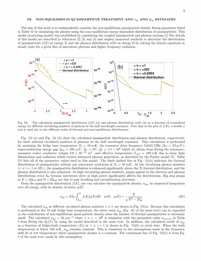
The aim of this work is to independently examine the non-equilibrium quasiparticle density fitting parameter listedin Table SI by simulating the physics using the non-equilibrium energy-dependent distribution of quasiparticles. Thismodel (scattering model) was established by considering the coupled quasiparticle and phonon systems.[1] The detailsof this model are described in references [2] [3] and [4] and employ numerical methods to discretize the distributionof quasiparticles f(E) at energy E and the phonon distribution n(⌦) at energy ⌦ by solving the kinetic equations insteady state for a given flux of microwave photons and higher frequency radiation.
1 1.5 2 2.5 3E/
S0
10-20
10-15
10-10
10-5
f (E
)
10-200
10-150
10-100
10-50
< n > =1< n > =325 < n > = 4.25E5thermal distribution
(a)
0 0.5 1 1.5 2 2.5 / s0
10-25
10-20
10-15
10-10
10-5
100
n(
)
< n > =1< n > =325< n > =4.25E5thermal distribution
(b)
Fig. S2. The calculated quasiparticle distribution f(E) (a) and phonon distribution n(⌦) (b) as a function of normalizedenergy for di↵erent circulating numbers of photons in the half wavelength resonator. Note that in the plot of f(E), a double yaxis is used due to the di↵erent scales of thermal and non-equilibrium distributions.
Fig. S2 (a) and Fig. S2 (b) show the calculated quasiparticle distribution and phonon distribution, respectively,for three selected circulated numbers of photons in the half wavelength resonator. This calculation is performedby assuming the fridge base temperature Tb = 10 mK, the resonator drive frequency 3.6442 GHz (~! = 23 µeV ),superconducting energy gap �s0 = 188 µeV , Qi = 105, Qc = 1.5 ⇥ 106 which we obtain from fitting the resonance,resonator center conductor volume 8.6 ⇥ 10�14 m3 and e↵ective temperature Teff = 189 mK due to stray lightillumination and radiation which creates enhanced phonon generation, as described by the Parker model [5]. TableSII lists all of the parameter values used in this model. The black dashed line in Fig. S2(a) indicates the thermaldistribution of quasiparticles without any microwave excitation at Tb = 10 mK. At low circulating photon numbers(< n >= 1 or 325 ), the quasiparticle distribution is enhanced significantly above the Tb thermal distribution, and thephonon distribution is also enhanced. At high circulating photon numbers, jumps appear in the electron and phonondistributions every ~! because microwave drive at high power significantly a↵ects the distributions. Big step jumpsat E = 3�s0 and ⌦ = 2�s0 are due to pair breaking and recombination processes.
From the quasiparticle distribution f(E), one can calculate the quasiparticle density, nqp, by numerical integrationover all energy, with its density of states ⇢(E)
nqp = 4N0
Z 1
�s0
f(E)⇢(E)dE with ⇢(E) =Ep
E2 ��2s0
(S1)
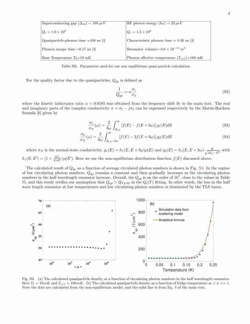
The calculated nqp at di↵erent circulated photon numbers < n > are shown in Fig. S3(a). Because this calculationis performed at the 10 mK fridge base temperature, the entire term nqp (Eq. (8) of the main text) can be regardedas the contribution of non-equilibrium quasi-particle density since the number of thermal quasiparticles is extremelysmall. The calculated nqp ⇠ 50 µm�3 when < n > < 106 is consistent with the parameter value nnon,eq in TableI from fitting the Qi(T ) by using the model described in the main text. In addition, the calculated result of nqp
as a function of fridge/bath temperature (Tb) at < n >= 1 is shown in Fig. S3(b) as circle dots. When the bathtemperature is below 150 mK, nqp remains constant. This is consistent to the assumptions made in the frequencyshift fit at low temperature where quasiparticle density is a constant. The continuous line of Fig. S3(b) is from Eq.8 of the main text, made by this assumption.
4
Superconducting gap (�s0) = 188 µeV RF photon energy (~!) = 23 µeV
Qi = 1.0⇥ 105 Qc = 1.5⇥ 106
Quasiparticle-phonon time =438 ns [3] Characteristic phonon time = 0.26 ns [3]
Phonon escape time =0.17 ns [3] Resonator volume= 8.6⇥ 10�14 m3
Base Temperature Tb=10 mK Phonon e↵ective temperature (Teff )=189 mK
Table SII. Parameters used for our non equilibrium quasi-particle calculation.
For the quality factor due to the quasiparticles, Qqp is defined as
1
Qqp= ↵
�1
�2(S2)
where the kinetic inductance ratio ↵ = 0.0185 was obtained from the frequency shift fit in the main text. The realand imaginary parts of the complex conductivity � = �1 � j�2 can be expressed respectively by the Mattis-Bardeenformula [6] given by
�1
�N(!) =
2
~!
Z 1
�s0
[f(E)� f(E + ~!)] g1(E)dE (S3)
�2
�N(!) =
2
~!
Z 1
�s0�~![f(E)� 2f(E + ~!)] g2(E)dE (S4)
where �N is the normal-state conductivity, g1(E) = h1(E,E + ~!)⇢(E) and g2(E) = h1(E,E + ~!) Ep�2
s0�E2with
h1(E,E0) = (1 + �2s0
E⇤E0 )⇢(E0). Here we use the non-equilibrium distribution function f(E) discussed above.
The calculated result of Qqp as a function of average circulated photon numbers is shown in Fig. S4. In the regimeof low circulating photon numbers, Qqp remains a constant and then gradually increases as the circulating photonnumbers in the half wavelength resonator increase. Overall, the Qqp is on the order of 107, close to the values in TableSI, and this result verifies our assumption that Qqp > QTLS0 in the Qi(T ) fitting. In other words, the loss in the halfwave length resonator at low temperatures and low circulating photon numbers is dominated by the TLS losses.
100
102
104
106
< n >
45
50
55
60
65
70
nq
p (
1/
m3)
(a)
0 0.05 0.1 0.15 0.2 0.25
Temperature (K)
0
200
400
600
800
1000
nqp (
1/
m3)
Simulation data fromscattering model
Analytical formula
(b)
Fig. S3. (a) The calculated quasiparticle density as a function of circulating photon numbers in the half wavelength resonator.Here Tb = 10mK and Teff = 189mK. (b) The calculated quasiparticle density as a function of fridge temperature at < n >= 1.Note the dots are calculated from the non-equilibrium model, and the solid line is from Eq. 8 of the main text.

5
100 102 104 106
< n >
106
107
108
p
Fig. S4. The calculated quality factor of quasi-particle as a function of circulating photon numbers < n > in the halfwavelength resonator. Here Tb = 10mK and Teff = 189mK, and other parameters are listed in Table SII.
IV. CST MICROWAVE SIMULATION OF CPW ELECTRIC FIELDS
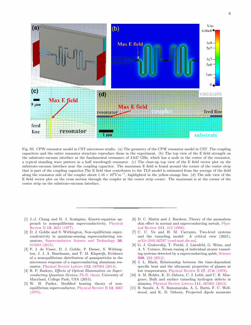
A model of the CPW microwave resonator was constructed in CST Microwave Studio. The model structure (Fig.S5) represents the entire CPW resonator and coupling capacitors, both of which reproduce the geometrical structurein our superconducting chip. The superconductor is modeled as a perfect electric conductor for the purpose of E fieldcalculation. The results below are obtained from the finite element frequency domain solver in CST.
The CST simulation shows that on resonance at 3.647 GHz, the electric field can attain a maximum of 6 ⇥ 108
V/m on the substrate-vacuum interface at the corner of the center strip that is part of the coupling capacitor on theinput side. This calculation was done under a 0.5 watt excitation level. An average electric field of the adjacent areais estimated to be ⇠ 1.16⇥ 108 V/m. By scaling this power down to that required to achieve one circulating photonin the resonator, we estimate the average electric field of the region nearby the coupling capacitor of the resonator tobe 0.2 V/m. In Fig. 5 of the main text, the E field on the x-axis is estimated from this scaling and extended to theother circulating photon numbers in the resonator.
V. TWO-LEVEL SYSTEM MODEL PARAMETER ESTIMATES AND COMPARISON TO DATA
Here we estimate from first principles the magnitude of eA = ⇣ ⇥E2 (Eq. (7) of the main text) and compare to thevalues derived from fits to the eA vs. electric field experimental data shown in Fig. 5 of the main text.
eA =
4d203"2
�2L
v5L+
�2T
v5T
��1⇡2⇢2~3v2C�2P0kB�
!E2 ⌘ ⇣E2 (S5)
We make use of the extensive literature on TLS in glasses at low temperatures, as well as the more recent literature onindividual TLS spectroscopy. It is observed experimentally that the average properties of TLS in glass are essentiallyuniversal,[7] hence in that spirit we use values of the parameters that are gathered from di↵erent glasses. Thiscalculation is intended as no more than an order of magnitude estimate to see if the experimental value for ⇣ isroughly on the scale of what we expect from widely accepted microscopic parameters.
The parameters used to estimate ⇣ are shown in Table SIII, along with the source for each value. We note that therecent experiments on single TLS spectroscopy extract values for these parameters that are close to those from the low-temperature glass literature. For example, values of the deformation potential for aluminum oxide of � ⇡ 0.2� 0.4eVare extracted from single TLS measurements,[8] a bit lower than the value of � obtained from measurements of fusedsilica glasses.[9]
Using the numbers in Table SIII we find that ⇣estimated = 2.6⇥ 10�3K ⇤m2/V 2. This is close to the experimentalvalue extracted from the fit to the data in Fig. 5 of the main text, namely ⇣exp = 3.49⇥ 10�3K ⇤m2/V 2. Hence webelieve that the experimentally obtained value for ⇣ is reasonable.
6
Fig. S5. CPW resonator model in CST microwave studio. (a) The geometry of the CPW resonator model in CST. The couplingcapacitors and the entire resonator structure reproduce those in the experiment. (b) The top view of the E field strength onthe substrate-vacuum interface at the fundamental resonance of 3.647 GHz, which has a node in the center of the resonator,a typical standing wave pattern in a half wavelength resonator. (c) The close-up top view of the E field vector plot on thesubstrate-vacuum interface near the coupling capacitor. The maximum E field is found around the corner of the center stripthat is part of the coupling capacitor.The E field that contributes to the TLS model is estimated from the average of the fieldalong the resonator side of the coupler about 1.16⇥ 108V m�1, highlighted in the yellow-orange line. (d) The side view of theE field vector plot on the cross section through the coupler at the center strip corner. The maximum is at the corner of thecenter strip on the substrate-vacuum interface.
[1] J.-J. Chang and D. J. Scalapino, Kinetic-equation ap-proach to nonequilibrium superconductivity, PhysicalReview B 15, 2651 (1977).
[2] D. J. Goldie and S. Withington, Non-equilibrium super-condcutivity in quantum-sensing superconducting res-onators, Superconductor Science and Technology 26,015004 (2013).
[3] P. J. de Visser, D. J. Goldie, P. Diener, S. Withing-ton, J. J. A. Baselmans, and T. M. Klapwijk, Evidenceof a nonequilibrium distribution of quasiparticles in themicrowave response of a superconducting aluminum res-onator, Physical Review Letters 112, 047004 (2014).
[4] R. P. Budoyo, E↵ects of Optical Illumination on Super-
conducting Quantum Devices, Ph.D. thesis, University ofMaryland, College Park, USA (2015).
[5] W. H. Parker, Modified heating theory of non-equilibrium superconductor, Physical Review B 12, 3667(1975).
[6] D. C. Mattis and J. Bardeen, Theory of the anomalousskin e↵ect in normal and superconducting metals, Phys-ical Review 111, 412 (1958).
[7] C. C. Yu and H. M. Carruzzo, Two-level systemsand the tunneling model: A critical view (2021),arXiv:2101.02787 [cond-mat.dis-nn].
[8] G. J. Grabovskij, T. Peichl, J. Lisenfeld, G. Weiss, andA. V. Ustinov, Strain tuning of individual atomic tunnel-ing systems detected by a superconducting qubit, Science338, 232 (2012).
[9] J. L. Black, Relationship between the time-dependentspecific heat and the ultrasonic properties of glasses atlow temperatures, Physical Review B 17, 2740 (1978).
[10] A. M. Holder, K. D. Osborn, C. J. Lobb, and C. B. Mus-grave, Bulk and surface tunneling hydrogen defects inalumina, Physical Review Letters 111, 065901 (2013).
[11] B. Sarabi, A. N. Ramanayaka, A. L. Burin, F. C. Well-stood, and K. D. Osborn, Projected dipole moments

7
Parameter Symbol Value and units Comments and ReferenceTransition dipole moment d0 1 e� A Order of magnitude estimate based on Refs. [10],[11]TLS energy level splitting " hf = 2.41⇥ 10�24J Energy level splitting matches photon energyTLS well o↵set energy � hf = 2.41⇥ 10�24J Energy level asymmetry on the scale of photon energy
TLS DOS*Longitudinal Deformation Potential P0�2L 1.4⇥ 107J/m3 Fused silica value [9]
TLS DOS*Transverse Deformation Potential P0�2T 0.63⇥ 107J/m3 Fused silica value [9]
Longitudinal Sound Velocity vL 5.8⇥ 103m/s Fused silica value [9]Transverse Sound Velocity vT 3.8⇥ 103m/s Fused silica value [9]
Mass Density ⇢ 2.2⇥ 103kg/m3 Fused silica value [9]Averaged Sound Velocity v 4.16⇥ 103m/s Assuming 1/v3 = 1
3
P3s=1
1v3s[7]
Dimensionless Phonon scattering rate [7] C 1 Reference [12]Deformation Potential � 1.6eV Fused silica value [9]
Electric Field at Single-Photon Level E 0.22V/m Estimated from CPW full-wave simulation
Table SIII. Table of estimated parameters that go into a calculation of the quantity eA = ⇣E2, Eq. (7) of the main text. Arepresentative value of each parameter is chosen for use in an order of magnitude estimate of ⇣.
DOS = density of states.
of individual two-level defects extracted using circuitquantum electrodynamics, Physical Review Letters 116,167002 (2016).
[12] C. Yu and A. Leggett, Low temperature properties of
amorphous materials: Through a glass darkly, CommentsCond. Mat. Phys 14, 231 (1988).


![[Coherence] coherence 모니터링 v 1.0](https://img.pdfslide.net/doc/110x75/54c1fc894a79599f448b456b/coherence-coherence-v-10.jpg)
