Embed Size (px)
Citation preview
Entangling two superconducting LC coherent modes via a superconducting flux qubit
Mei-Yu Chen, Matisse W. Y. Tu, and Wei-Min Zhang*Department of Physics and Center for Quantum Information Science, National Cheng Kung University, Tainan 70101,
Taiwan and National Center for Theoretical Science, Tainan 70101, Taiwan�Received 9 March 2009; revised manuscript received 25 April 2009; published 31 December 2009�
Based on a pure solid-state device consisting of two superconducting LC circuits coupled to a supercon-ducting flux qubit, we propose in this paper that the maximally entangled coherent states of the two LC modescan be generated for arbitrary coherent states through flux qubit controls.
DOI: 10.1103/PhysRevB.80.214538 PACS number�s�: 85.25.Cp, 03.67.Bg, 42.50.Dv
I. INTRODUCTION
Quantum entanglement is not only of interests in the fun-damentals of quantum mechanics concerning the EPRparadox1 but also serves as an indispensable resource forquantum information processing.2 Many discrete entangledstates in terms of polarized photons, atoms, trapped ions, andelectrons in nanostructures have been experimentally demon-strated. However their practical applications suffer fromsingle-particle decoherence severely. Therefore, increasingattention has been paid to generating macroscopic entangledstates3–6 due to their robustness against single-particle deco-herence. The entangled coherent states is one of the mostimportant ingredients of quantum information processing us-ing coherent states.7 Creating entangled coherent states, ini-tially proposed by Sanders in quantum optics,8 have beenextensively explored in many other systems, such as trappedions,9 microwave cavity QED,10 Boson-Einstein Condensa-tion �BEC� system,11 as well as the nanomechanicalsystems12 but not yet realized experimentally.
Motivated by the recent experiments on strong couplingbetween superconducting LC resonators and superconduct-ing flux qubits,13,14 we propose in this paper a pure electronic�solid-state� device for generating entangled coherent statesof two superconducting LC modes through flux qubit con-trols. Using superconducting qubits coupled with a LC reso-nator �as a quantum bus� to generate superconducting qubitcouplings, to build two-qubit entanglement, and to imple-ment two-qubit logic gates have been extensively studied forquantum information processing in the past years.15–25 Here,we shall design an alternative superconducting circuits thatusing the measurement of superconducting flux qubit statesto generate the maximum entanglement states of the two LCcoherent modes for quantum communication. The scheme ofgenerating entanglement states of distant systems throughmeasurement was indeed proposed a decade ago.26 However,LC circuits are building blocks of all the electronic informa-tion and communication devices used today, this entangledLC coherent mode generator could be very promising forpractical realization of quantum communication and quan-tum information processing.
II. SYSTEM SETUP
The device we design here consists of two superconduct-ing LC circuits strongly coupled to a superconducting flux
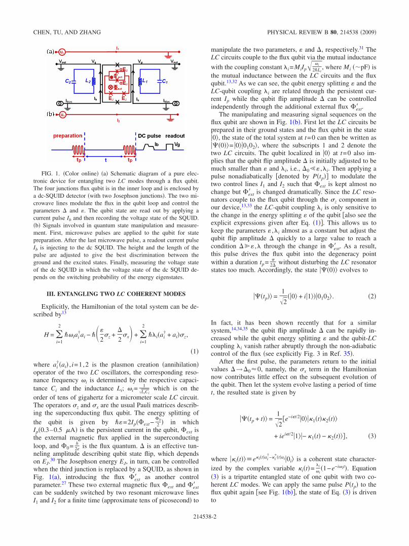
qubit. Figure 1�a� is a schematic setup of our superconduct-ing circuits. The central circuit is a superconducting flux qu-bit which is coupled to two superconducting LC circuitsthrough mutual inductance. The qubit is enclosed by a super-conducting quantum interference device �SQUID� as a qubitmeasurement device. Coherent control of the qubit isachieved via two microwave control lines �I1 , I2�. Symmetriccircuits are designed to suppress excitation of the SQUIDand to protect the two LC oscillators from the unwantedinfluence of the qubit controlling pulses.
Both the superconducting LC circuits and the flux qubitcan be fabricated on a chip down to the micrometer scale.The superconducting LC circuit is an ideal harmonic oscilla-tor verified experimentally,13 and the two levels of the super-conducting flux qubit comprise of the clockwise and coun-terclockwise persistent-current states �0� and �1�.27,28 Thelatter is made of a superconducting loop interrupted by threeJosephson junctions27 in which two junctions have the sameJosephson coupling energy EJ, and the third junction �placedby a SQUID in Fig. 1�a�� has the coupling energy smallerthan that of the other two junctions by a factor � with 0.5���1. The interaction of the flux qubit and two LC circuitscan be controlled by the external microwave control lines.The geometrical structure of the LC circuit is adjustable sothat the strong coupling can be achieved.13 The flux qubit isalso tunable and has the advantage of long-decoherence time.These advantages decrease the difficulty of the experimentand increase the feasibility.
Preparing the flux qubit in a superposition of the states �0�and �1� initially, we are able to drive the qubit and the twoLC modes into a tripartite entanglement �see Fig. 1�b� andEq. �4��. Measuring the qubit state with an enclosed dcSQUID, which is inductively coupled to the qubit28,29 asshown in Fig. 1�a�, will generate the entangled LC coherentmodes. This is the procedure of entangling two supercon-ducting LC coherent modes through flux qubit controls. Asschematically depicted in Fig. 1�a�, the qubit detector con-sists of a ring interrupted by two Josephson junctions. ThisSQUID is connected in such a way that the current can beinjected through the parallel junctions. The switching currentof the detector is sensitive to the flux produced by the currentof the flux qubit. The readout of the qubit state is performedby applying a pulse sequence to the SQUID, as shown in Fig.1�b�, and recording whether the SQUID had been switchedto a finite voltage �Vg� or remained in the zero voltage.
PHYSICAL REVIEW B 80, 214538 �2009�
1098-0121/2009/80�21�/214538�5� ©2009 The American Physical Society214538-1
III. ENTANGLING TWO LC COHERENT MODES
Explicitly, the Hamiltonian of the total system can be de-scribed by13
H = �i=1
2
��iai†ai − ���
2�z +
�
2�x + �
i=1
2
��i�ai† + ai��z,
�1�
where ai†�ai� , i=1,2 is the plasmon creation �annihilation�
operator of the two LC oscillators, the corresponding reso-nance frequency �i is determined by the respective capaci-tance Ci and the inductance Li; �i=
1LiCi
which is on theorder of tens of gigahertz for a micrometer scale LC circuit.The operators �z and �x are the usual Pauli matrices describ-ing the superconducting flux qubit. The energy splitting ofthe qubit is given by ��=2Ip�ext−
0
2 � in whichIp�0.3–0.5 A� is the persistent current in the qubit, ext isthe external magnetic flux applied in the superconductingloop, and 0= h
2e is the flux quantum. � is an effective tun-neling amplitude describing qubit state flip, which dependson EJ.
30 The Josephson energy EJ, in turn, can be controlledwhen the third junction is replaced by a SQUID, as shown inFig. 1�a�, introducing the flux ext� as another controlparameter.27 These two external magnetic flux ext and ext�can be suddenly switched by two resonant microwave linesI1 and I2 for a finite time �approximate tens of picosecond� to
manipulate the two parameters, � and �, respectively.31 TheLC circuits couple to the flux qubit via the mutual inductance
with the coupling constant �i=MiIp �i
2�Li, where Mi ��pF� is
the mutual inductance between the LC circuits and the fluxqubit.13,32 As we can see, the qubit energy splitting � and theLC-qubit coupling �i are related through the persistent cur-rent Ip while the qubit flip amplitude � can be controlledindependently through the additional external flux ext� .
The manipulating and measuring signal sequences on theflux qubit are shown in Fig. 1�b�. First let the LC circuits beprepared in their ground states and the flux qubit in the state�0�, the state of the total system at t=0 can then be written as���0��= �0��0102�, where the subscripts 1 and 2 denote thetwo LC circuits. The qubit localized in �0� at t=0 also im-plies that the qubit flip amplitude � is initially adjusted to bemuch smaller than � and �i, i.e., �0�� ,�i. Then applying apulse nonadiabatically �denoted by P�tp�� to modulate thetwo control lines I1 and I2 such that ext is kept almost nochange but ext� is changed dramatically. Since the LC reso-nators couple to the flux qubit through the �z component inour device,13,33 the LC-qubit coupling �i is only sensitive tothe change in the energy splitting � of the qubit �also see theexplicit expressions given after Eq. �1��. This allows us tokeep the parameters � ,�i almost as a constant but adjust thequbit flip amplitude � quickly to a large value to reach acondition � � ,� through the change in ext� . As a result,this pulse drives the flux qubit into the degeneracy pointwithin a duration tp= �
2� without disturbing the LC resonatorstates too much. Accordingly, the state ���0�� evolves to
���tp�� =12
��0� + i�1���0102� . �2�
In fact, it has been shown recently that for a similarsystem,14,34,35 the qubit flip amplitude � can be rapidly in-creased while the qubit energy splitting � and the qubit-LCcoupling �i vanish rather abruptly through the non-adiabaticcontrol of the flux �see explicitly Fig. 3 in Ref. 35�.
After the first pulse, the parameters return to the initialvalues �→�0�0, namely, the �x term in the Hamiltoniannow contributes little effect on the subsequent evolution ofthe qubit. Then let the system evolve lasting a period of timet, the resulted state is given by
���tp + t�� =12
�e−i�t/2�0���1�t��2�t��
+ iei�t/2�1��− �1�t� − �2�t��� , �3�
where ��i�t�� e�i�t�ai†−�i
��t�ai�0i� is a coherent state character-ized by the complex variable �i�t�=
�i
�i�1−e−i�it�. Equation
�3� is a tripartite entangled state of one qubit with two co-herent LC modes. We can apply the same pulse P�tp� to theflux qubit again �see Fig. 1�b��, the state of Eq. �3� is drivento
FIG. 1. �Color online� �a� Schematic diagram of a pure elec-tronic device for entangling two LC modes through a flux qubit.The four junctions flux qubit is in the inner loop and is enclosed bya dc-SQUID detector �with two Josephson junctions�. The two mi-crowave lines modulate the flux in the qubit loop and control theparameters � and �. The qubit state are read out by applying acurrent pulse Ib and then recording the voltage state of the SQUID.�b� Signals involved in quantum state manipulation and measure-ment. First, microwave pulses are applied to the qubit for statepreparation. After the last microwave pulse, a readout current pulseIb is injecting to the dc SQUID. The height and the length of thepulse are adjusted to give the best discrimination between theground and the excited states. Finally, measuring the voltage stateof the dc SQUID in which the voltage state of the dc SQUID de-pends on the switching probability of the energy eigenstates.
CHEN, TU, AND ZHANG PHYSICAL REVIEW B 80, 214538 �2009�
214538-2

���tp + t + tp�� =1
2e−i�t/2��0����1��t��2��t�� − ei�t�
− �1��t� − �2��t��� + i�1����1��t��2��t��
+ ei�t�− �1��t� − �2��t���� , �4�
where �i��t�=�i�t�e−i�itp. We now measure the flux qubit inthe �z basis, i.e., the natural computational basis ��0� , �1��which is indeed the energy eigenstate basis in the presentcase since �→�0�� after the second pulse. As a result, thetwo LC modes collapse into the state,
��+�12 =12
���1��t��2��t�� + ei�t�− �1��t� − �2��t��� �5�
if the qubit is measured with the result 1 or
��−�12 =1
2����1��t��2��t�� − ei�t�− �1��t� − �2��t���� �6�
if the measured result is 0. Each outcome has a probability of50% to occur. Equations �5� and �6� are two entangled co-herent states of the two superconducting LC circuits we pro-pose to generate.
In practice, we are more interested in the case of the twosuperconducting LC circuits being symmetric in geometryfor protecting the two LC oscillators from the unwanted in-fluence of the qubit controlling pulses. Thus we have �1=�2 � and �1=�2 �. Let the system evolve for a periodof time t= �
� between the two pulses, we obtain the followingstandard form of the entangled two LC coherent states:
����12 =1
2��2�02�0� � ei��− 2�0 − 2�0�� �7�
with �0= �
�e−i�tp and �=��
� . Using the concept of concur-rence for bipartite entangled nonorthogonal states,9,36 it iseasy to show that the concurrence for ����12 is given by
C��=
1 − e−16��0�2
1 � e−16��0�2 cos �. �8�
If the rate ��0�= �
� �0.5, the exponential factor e−16�02�1.
Then we have C���1, namely, ����12 are nearly maximally
entangled even though the average boson number �=4��0�2�in the coherent state �2�0� is a small number. By well-designed circuits, one can let the ratio of coupling constant tothe resonance frequency near to 1, i.e., �0�1, then��−2�0 �2�0��2=e−16��0�2 �10−7�0, namely, the two coherentstates �−2�0� and �2�0� in the entangled state �Eq. �7�� can benearly orthogonal.
However, if the average boson number is too small, thecoherent states ��i�t�� are not truly macroscopic states suchthat the robustness against decoherence for the correspond-ing entanglement states could be faded. This weakness canbe overcome by preparing the two LC circuits initially in twocoherent states ��1� and ��2� while the flux qubit is still in theground state �0�. The initial state of the total system becomes����0��= �0���1�2�. Similarly using the pulse P�tp� to rotatethe qubit state, ����tp��= 1
2��0�+ i�1����1��2��, where �i�
=�ie−i�itp. Then let the system evolve for a period of time t,
the resulting state of the total system is
����tp + t�� =12
�e−i��0���1+�t��2+�t�� + iei��1���1−�t��2−�t��� .
�9�
Here we have defined ��i��t�� ��i�e−i�it��i�t�� and �= �
2 t
+ i��1+�2� with �i �i
2�i��ei�it−1��i�
�+ �1−e−i�it��i��. Againwe can measure the flux qubit in the �z basis after reapplyingthe pulse P�tp� to the qubit, which results in the followingentangled coherent states:
���� �12 =12
���1+� �t��2+� �t�� � ei2���1−� �t��2−� �t��� , �10�
where �i�� =�i�e−i�itp. Now, the coherent states ��i�� �t�� canbe a very macroscopic state, depending on the initial volt-ages applied to the two LC circuits for generating the initialtwo coherent states ��i�. While the entanglement measures of���� �12 are almost the same as that of ����12. To be specific,we consider the symmetric LC circuits again with �1=�2
� and take t= �� , the concurrence for ���� �12 is given by
C���
=1 − e−16��0�2
1 � e−16��0�2 cos�� − 16��0�Im ���. �11�
It shows that for a given ��0�= �
� such that e−16��0�2 �1, wecan always have C�
���1 regardless of the value of ��
=�ei�tp. In other words, the device we proposed here cangenerate maximally entangled states for arbitrary coherentstates with arbitrary large oscillating amplitudes.
IV. DECOHERENCE ANALYSIS AND CONCLUSION
We have shown how to entangle two LC coherent modesthrough a superconducting flux qubit. To make the devicefeasible, we should also analyze various possible decoher-ence effect to the system. In solid-state systems decoherencecomes from many redundant degrees of freedom that interactwith the device. The noise may due to the emission from thesuperconducting LC circuits and the flux qubit, and from thecontrol and detect of the qubit state. �i� In fact, the decoher-ence of the entangled coherent state due to the photoloss hasbeen analyzed in detail recently by one of us in Ref. 37. �ii�Recent experiments demonstrated that the relaxation anddephasing times of the flux qubit are greater than0.1 s,14,25,38,39 longer enough for qubit operations which ison the order of tens of picoseconds, estimated from tp= �
2��40 ps for ��40 GHz.30 �iii� The SQUID may be induc-tively coupled to the two LC oscillators. But from the esti-mation of the Johnson-Nyquist noise in the bias circuit, it hasbeen shown that this contribution is several orders of mag-nitude weaker.13,40 �iv� The symmetric design of the LC aswell as the dc-SQUID circuits has effectively suppressed thenoise induced by qubit operations.13,25,28,30 Put all these de-coherence effects together, the estimated decoherence timesfrom the different source are much longer than the typicaltime scale �the pulse time tp�40 ps and evolving time t
ENTANGLING TWO SUPERCONDUCTING LC COHERENT… PHYSICAL REVIEW B 80, 214538 �2009�
214538-3
= �� �0.1 ns for ��40 GHz �Ref. 13�� of the system for
producing entangled coherent states, which makes the sys-tem more practical.
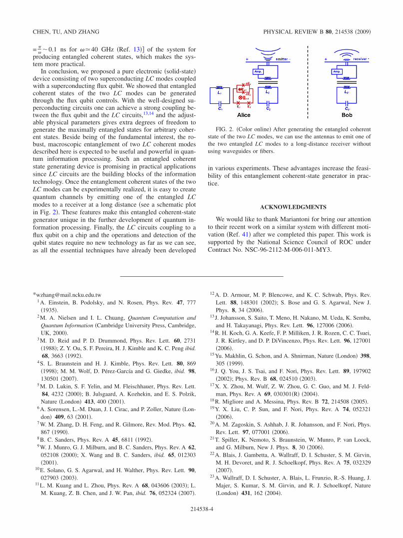
In conclusion, we proposed a pure electronic �solid-state�device consisting of two superconducting LC modes coupledwith a superconducting flux qubit. We showed that entangledcoherent states of the two LC modes can be generatedthrough the flux qubit controls. With the well-designed su-perconducting circuits one can achieve a strong coupling be-tween the flux qubit and the LC circuits,13,14 and the adjust-able physical parameters gives extra degrees of freedom togenerate the maximally entangled states for arbitrary coher-ent states. Beside being of the fundamental interest, the ro-bust, macroscopic entanglement of two LC coherent modesdescribed here is expected to be useful and powerful in quan-tum information processing. Such an entangled coherentstate generating device is promising in practical applicationssince LC circuits are the building blocks of the informationtechnology. Once the entanglement coherent states of the twoLC modes can be experimentally realized, it is easy to createquantum channels by emitting one of the entangled LCmodes to a receiver at a long distance �see a schematic plotin Fig. 2�. These features make this entangled coherent-stategenerator unique in the further development of quantum in-formation processing. Finally, the LC circuits coupling to aflux qubit on a chip and the operations and detection of thequbit states require no new technology as far as we can see,as all the essential techniques have already been developed
in various experiments. These advantages increase the feasi-bility of this entanglement coherent-state generator in prac-tice.
ACKNOWLEDGMENTS
We would like to thank Mariantoni for bring our attentionto their recent work on a similar system with different moti-vation �Ref. 41� after we completed this paper. This work issupported by the National Science Council of ROC underContract No. NSC-96-2112-M-006-011-MY3.
*[email protected] A. Einstein, B. Podolsky, and N. Rosen, Phys. Rev. 47, 777
�1935�.2 M. A. Nielsen and I. L. Chuang, Quantum Computation and
Quantum Information �Cambridge University Press, Cambridge,UK, 2000�.
3 M. D. Reid and P. D. Drummond, Phys. Rev. Lett. 60, 2731�1988�; Z. Y. Ou, S. F. Pereira, H. J. Kimble and K. C. Peng ibid.68, 3663 �1992�.
4 S. L. Braunstein and H. J. Kimble, Phys. Rev. Lett. 80, 869�1998�; M. M. Wolf, D. Pérez-García and G. Giedke, ibid. 98,130501 �2007�.
5 M. D. Lukin, S. F. Yelin, and M. Fleischhauer, Phys. Rev. Lett.84, 4232 �2000�; B. Julsgaard, A. Kozhekin, and E. S. Polzik,Nature �London� 413, 400 �2001�.
6 A. Sorensen, L.-M. Duan, J. I. Cirac, and P. Zoller, Nature �Lon-don� 409, 63 �2001�.
7 W. M. Zhang, D. H. Feng, and R. Gilmore, Rev. Mod. Phys. 62,867 �1990�.
8 B. C. Sanders, Phys. Rev. A 45, 6811 �1992�.9 W. J. Munro, G. J. Milburn, and B. C. Sanders, Phys. Rev. A 62,
052108 �2000�; X. Wang and B. C. Sanders, ibid. 65, 012303�2001�.
10 E. Solano, G. S. Agarwal, and H. Walther, Phys. Rev. Lett. 90,027903 �2003�.
11 L. M. Kuang and L. Zhou, Phys. Rev. A 68, 043606 �2003�; L.M. Kuang, Z. B. Chen, and J. W. Pan, ibid. 76, 052324 �2007�.
12 A. D. Armour, M. P. Blencowe, and K. C. Schwab, Phys. Rev.Lett. 88, 148301 �2002�; S. Bose and G. S. Agarwal, New J.Phys. 8, 34 �2006�.
13 J. Johansson, S. Saito, T. Meno, H. Nakano, M. Ueda, K. Semba,and H. Takayanagi, Phys. Rev. Lett. 96, 127006 �2006�.
14 R. H. Koch, G. A. Keefe, F. P. Milliken, J. R. Rozen, C. C. Tsuei,J. R. Kirtley, and D. P. DiVincenzo, Phys. Rev. Lett. 96, 127001�2006�.
15 Yu. Makhlin, G. Schon, and A. Shnirman, Nature �London� 398,305 �1999�.
16 J. Q. You, J. S. Tsai, and F. Nori, Phys. Rev. Lett. 89, 197902�2002�; Phys. Rev. B 68, 024510 �2003�.
17 X. X. Zhou, M. Wulf, Z. W. Zhou, G. C. Guo, and M. J. Feld-man, Phys. Rev. A 69, 030301�R� �2004�.
18 R. Migliore and A. Messina, Phys. Rev. B 72, 214508 �2005�.19 Y. X. Liu, C. P. Sun, and F. Nori, Phys. Rev. A 74, 052321
�2006�.20 A. M. Zagoskin, S. Ashhab, J. R. Johansson, and F. Nori, Phys.
Rev. Lett. 97, 077001 �2006�.21 T. Spiller, K. Nemoto, S. Braunstein, W. Munro, P. van Loock,
and G. Milburn, New J. Phys. 8, 30 �2006�.22 A. Blais, J. Gambetta, A. Wallraff, D. I. Schuster, S. M. Girvin,
M. H. Devoret, and R. J. Schoelkopf, Phys. Rev. A 75, 032329�2007�.
23 A. Wallraff, D. I. Schuster, A. Blais, L. Frunzio, R.-S. Huang, J.Majer, S. Kumar, S. M. Girvin, and R. J. Schoelkopf, Nature�London� 431, 162 �2004�.
FIG. 2. �Color online� After generating the entangled coherentstate of the two LC modes, we can use the antennas to emit one ofthe two entangled LC modes to a long-distance receiver withoutusing waveguides or fibers.
CHEN, TU, AND ZHANG PHYSICAL REVIEW B 80, 214538 �2009�
214538-4

24 D. I. Schuster, A. A. Houck, J. A. Schreier, A. Wallraff, J. M.Gambetta, A. Blais, L. Frunzio, J. Majer, B. R. Johnson, M. H.Devoret, S. M. Girvin, and R. J. Schoelkopf, Nature �London�445, 515 �2007�.
25 T. Hime, P. A. Reichardt, B. L. T. Plourde, T. L. Robertson, C.-E.Wu, A. V. Ustinov, and J. Clarke, Science 314, 1427 �2006�.
26 C. Cabrillo, J. I. Cirac, P. Garcia-Fernandez, and P. Zoller, Phys.Rev. A 59, 1025 �1999�.
27 J. E. Mooij, T. P. Orlando, L. Levitov, Lin Tian, Caspar H. vander Wal, and Seth Lloyd, Science 285, 1036 �1999�.
28 I. Chiorescu, Y. Nakamura, C. J. P. M. Harmans, and J. E. Mooij,Science 299, 1869 �2003�.
29 D. Vion, A. Assime, A. Cottet, A. Cottet, H. Pothier, C. Urbina,D. Esteve, and M. H. Devoret, Science 296, 886 �2002�.
30 I. Chiorescu, P. Bertet, K. Semba, Y. Nakamura, C. J. P. M.Harmans, and J. E. Mooij, Nature �London� 431, 159 �2004�.
31 T. Kutsuzawa, H. Tanaka, S. Saito, H. Nakano, K. Semba, and H.Takayanagi, Appl. Phys. Lett. 87, 073501 �2005�.
32 A. Izmalkov, M. Grajcar, E. Ilichev, Th. Wagner, H.-G. Meyer,A. Yu. Smirnov, M. H. S. Amin, A. Maassen van den Brink, andA. M. Zagoskin, Phys. Rev. Lett. 93, 037003 �2004�.
33 A. J. Leggett, S. Chakravarty, A. T. Dorsey, M. P. Fisher, A.Garg, and W. Zwerger, Rev. Mod. Phys. 59, 1 �1987�.
34 R. H. Koch, J. R. Rozen, G. A. Keefe, F. M. Milliken, C. C.Tsuei, J. R. Kirtley, and D. P. DiVincenzo, Phys. Rev. B 72,092512 �2005�.
35 F. Brito, D. P. Divincenzo, R. H. Koch, and M. Steffen, New J.Phys. 10, 033027 �2008�.
36 X. Wang, J. Phys. A 35, 165 �2002�.37 J.-H. An and W. M. Zhang, Phys. Rev. A 76, 042127 �2007�; J.
H. Au, M. Feng and W. M. Zhang, Quantum Inf. Comput. 9,0317 �2009�.
38 F. Yoshihara, K. Harrabi, A. O. Niskanen, Y. Nakamura, and J. S.Tsai, Phys. Rev. Lett. 97, 167001 �2006�.
39 K. Kakuyanagi, T. Meno, S. Saito, H. Nakano, K. Semba, H.Takayanagi, F. Deppe, and A. Shnirman, Phys. Rev. Lett. 98,047004 �2007�.
40 L. Tian, S. Lloyd, and T. P. Orlando, Phys. Rev. B 65, 144516�2002�.
41 M. Mariantoni, F. Deppe, A. Marx, R. Gross, F. K. Wilhelm, andE. Solano, Phys. Rev. B 78, 104508 �2008�.
ENTANGLING TWO SUPERCONDUCTING LC COHERENT… PHYSICAL REVIEW B 80, 214538 �2009�
214538-5


![arXiv:1212.2558v2 [quant-ph] 21 Aug 2013 · arXiv:1212.2558v2 [quant-ph] 21 Aug 2013 Three-qubit Grover’s algorithm using superconducting quantum interferencedevices incavity-QED](https://img.pdfslide.net/doc/110x75/5e1dc9a508ba112f8f23626f/arxiv12122558v2-quant-ph-21-aug-2013-arxiv12122558v2-quant-ph-21-aug-2013.jpg)