Embed Size (px)
Citation preview
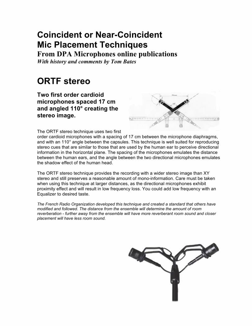
Coincident or Near-Coincident Mic Placement Techniques From DPA Microphones online publications With history and comments by Tom Bates ORTF stereo Two first order cardioid microphones spaced 17 cm and angled 110° creating the stereo image.
The ORTF stereo technique uses two first order cardioid microphones with a spacing of 17 cm between the microphone diaphragms, and with an 110° angle between the capsules. This technique is well suited for reproducing stereo cues that are similar to those that are used by the human ear to perceive directional information in the horizontal plane. The spacing of the microphones emulates the distance between the human ears, and the angle between the two directional microphones emulates the shadow effect of the human head. The ORTF stereo technique provides the recording with a wider stereo image than XY stereo and still preserves a reasonable amount of mono-information. Care must be taken when using this technique at larger distances, as the directional microphones exhibit proximity effect and will result in low frequency loss. You could add low frequency with an Equalizer to desired taste. The French Radio Organization developed this technique and created a standard that others have modified and followed. The distance from the ensemble will determine the amount of room reverberation - further away from the ensemble will have more reverberant room sound and closer placement will have less room sound.
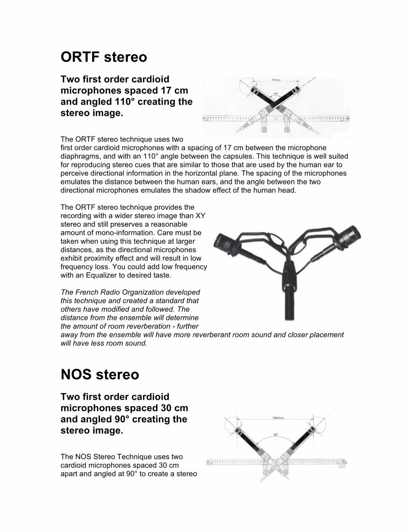
ORTF stereo Two first order cardioid microphones spaced 17 cm and angled 110° creating the stereo image.
The ORTF stereo technique uses two first order cardioid microphones with a spacing of 17 cm between the microphone diaphragms, and with an 110° angle between the capsules. This technique is well suited for reproducing stereo cues that are similar to those that are used by the human ear to perceive directional information in the horizontal plane. The spacing of the microphones emulates the distance between the human ears, and the angle between the two directional microphones emulates the shadow effect of the human head. The ORTF stereo technique provides the recording with a wider stereo image than XY stereo and still preserves a reasonable amount of mono-information. Care must be taken when using this technique at larger distances, as the directional microphones exhibit proximity effect and will result in low frequency loss. You could add low frequency with an Equalizer to desired taste. The French Radio Organization developed this technique and created a standard that others have modified and followed. The distance from the ensemble will determine the amount of room reverberation - further away from the ensemble will have more reverberant room sound and closer placement will have less room sound.
NOS stereo Two first order cardioid microphones spaced 30 cm and angled 90° creating the stereo image.
The NOS Stereo Technique uses two cardioid microphones spaced 30 cm apart and angled at 90° to create a stereo
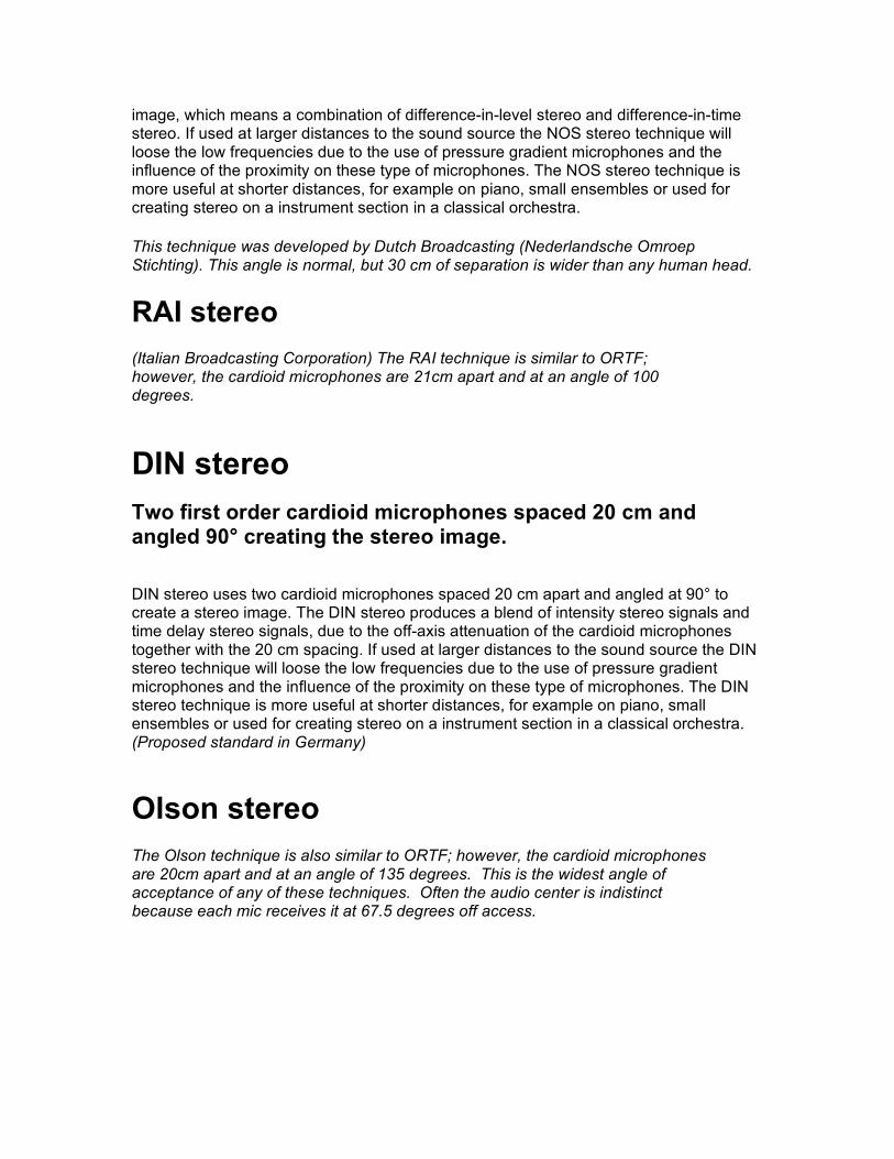
image, which means a combination of difference-in-level stereo and difference-in-time stereo. If used at larger distances to the sound source the NOS stereo technique will loose the low frequencies due to the use of pressure gradient microphones and the influence of the proximity on these type of microphones. The NOS stereo technique is more useful at shorter distances, for example on piano, small ensembles or used for creating stereo on a instrument section in a classical orchestra.
This technique was developed by Dutch Broadcasting (Nederlandsche Omroep Stichting). This angle is normal, but 30 cm of separation is wider than any human head.
RAI stereo (Italian Broadcasting Corporation) The RAI technique is similar to ORTF; however, the cardioid microphones are 21cm apart and at an angle of 100 degrees.
DIN stereo Two first order cardioid microphones spaced 20 cm and angled 90° creating the stereo image.
DIN stereo uses two cardioid microphones spaced 20 cm apart and angled at 90° to create a stereo image. The DIN stereo produces a blend of intensity stereo signals and time delay stereo signals, due to the off-axis attenuation of the cardioid microphones together with the 20 cm spacing. If used at larger distances to the sound source the DIN stereo technique will loose the low frequencies due to the use of pressure gradient microphones and the influence of the proximity on these type of microphones. The DIN stereo technique is more useful at shorter distances, for example on piano, small ensembles or used for creating stereo on a instrument section in a classical orchestra. (Proposed standard in Germany)
Olson stereo The Olson technique is also similar to ORTF; however, the cardioid microphones are 20cm apart and at an angle of 135 degrees. This is the widest angle of acceptance of any of these techniques. Often the audio center is indistinct because each mic receives it at 67.5 degrees off access.
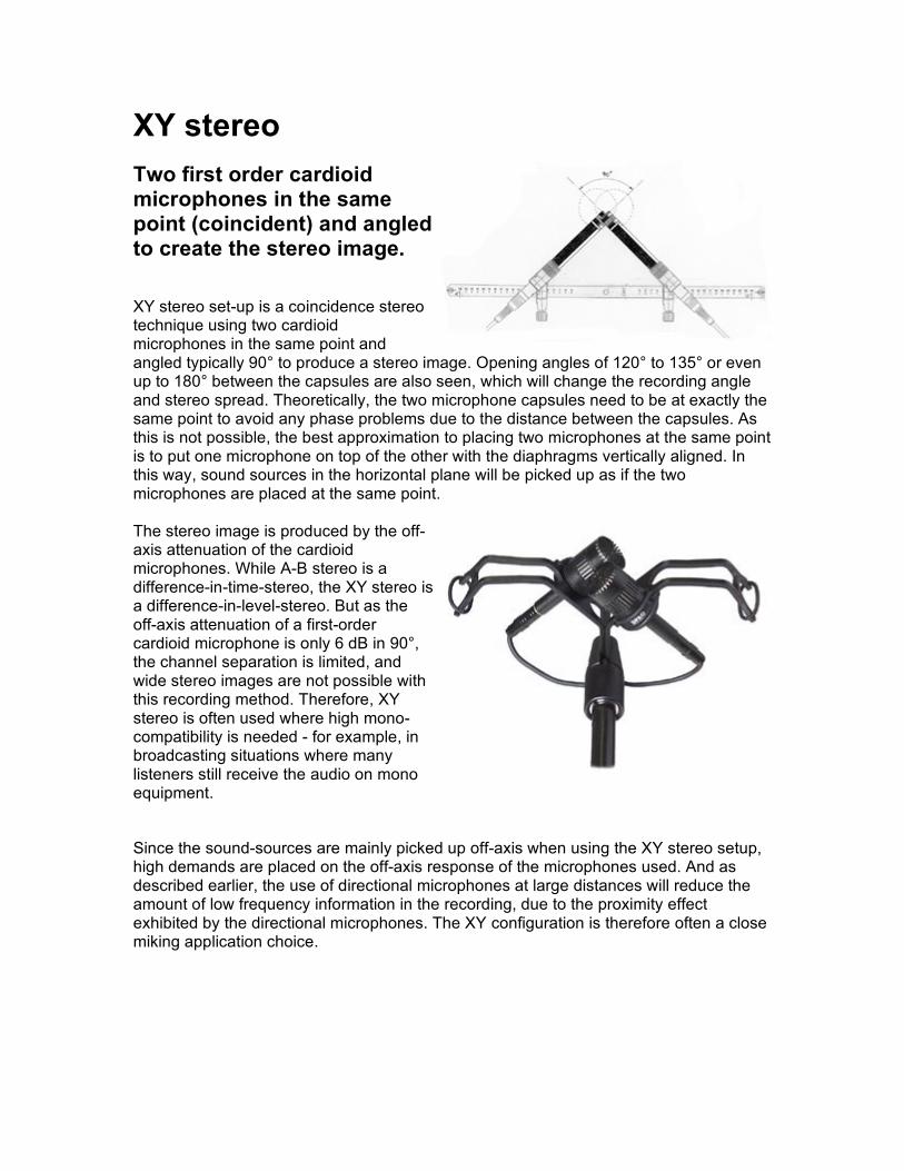
XY stereo Two first order cardioid microphones in the same point (coincident) and angled to create the stereo image.
XY stereo set-up is a coincidence stereo technique using two cardioid microphones in the same point and angled typically 90° to produce a stereo image. Opening angles of 120° to 135° or even up to 180° between the capsules are also seen, which will change the recording angle and stereo spread. Theoretically, the two microphone capsules need to be at exactly the same point to avoid any phase problems due to the distance between the capsules. As this is not possible, the best approximation to placing two microphones at the same point is to put one microphone on top of the other with the diaphragms vertically aligned. In this way, sound sources in the horizontal plane will be picked up as if the two microphones are placed at the same point. The stereo image is produced by the off-axis attenuation of the cardioid microphones. While A-B stereo is a difference-in-time-stereo, the XY stereo is a difference-in-level-stereo. But as the off-axis attenuation of a first-order cardioid microphone is only 6 dB in 90°, the channel separation is limited, and wide stereo images are not possible with this recording method. Therefore, XY stereo is often used where high mono-compatibility is needed - for example, in broadcasting situations where many listeners still receive the audio on mono equipment.
Since the sound-sources are mainly picked up off-axis when using the XY stereo setup, high demands are placed on the off-axis response of the microphones used. And as described earlier, the use of directional microphones at large distances will reduce the amount of low frequency information in the recording, due to the proximity effect exhibited by the directional microphones. The XY configuration is therefore often a close miking application choice.
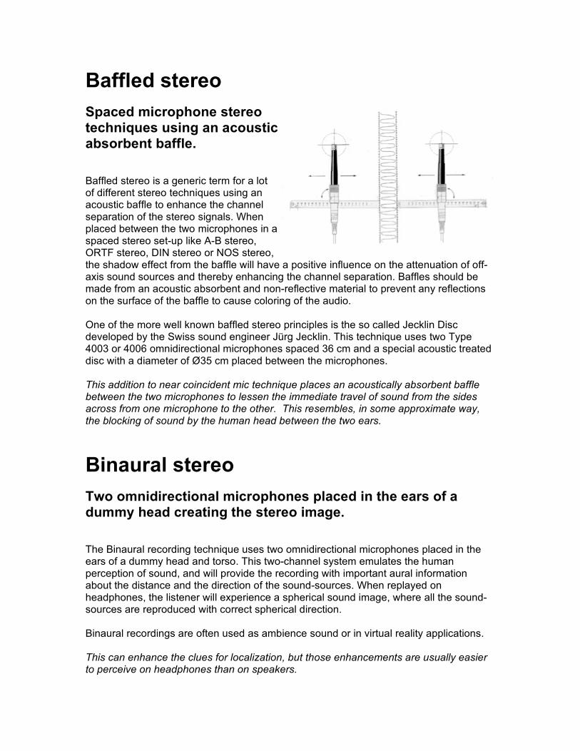
Baffled stereo Spaced microphone stereo techniques using an acoustic absorbent baffle.
Baffled stereo is a generic term for a lot of different stereo techniques using an acoustic baffle to enhance the channel separation of the stereo signals. When placed between the two microphones in a spaced stereo set-up like A-B stereo, ORTF stereo, DIN stereo or NOS stereo, the shadow effect from the baffle will have a positive influence on the attenuation of off-axis sound sources and thereby enhancing the channel separation. Baffles should be made from an acoustic absorbent and non-reflective material to prevent any reflections on the surface of the baffle to cause coloring of the audio. One of the more well known baffled stereo principles is the so called Jecklin Disc developed by the Swiss sound engineer Jürg Jecklin. This technique uses two Type 4003 or 4006 omnidirectional microphones spaced 36 cm and a special acoustic treated disc with a diameter of Ø35 cm placed between the microphones. This addition to near coincident mic technique places an acoustically absorbent baffle between the two microphones to lessen the immediate travel of sound from the sides across from one microphone to the other. This resembles, in some approximate way, the blocking of sound by the human head between the two ears.
Binaural stereo Two omnidirectional microphones placed in the ears of a dummy head creating the stereo image.
The Binaural recording technique uses two omnidirectional microphones placed in the ears of a dummy head and torso. This two-channel system emulates the human perception of sound, and will provide the recording with important aural information about the distance and the direction of the sound-sources. When replayed on headphones, the listener will experience a spherical sound image, where all the sound-sources are reproduced with correct spherical direction. Binaural recordings are often used as ambience sound or in virtual reality applications. This can enhance the clues for localization, but those enhancements are usually easier to perceive on headphones than on speakers.
Blumlein stereo Two bi-directional microphones placed in the same point and angled 90° creating the stereo image.
The Blumlein stereo set-up is a coincidence stereo technique, which uses two bi-directional microphones in the same point and angled at 90° to each other. This stereo technique will normally give the best results when used at shorter distances to the sound source, as bi-directional microphones are using the pressure gradient transducer technology and therefore is under influence of the proximity effect. At larger distances these microphones therefore will loose the low frequencies. The Blumlein stereo is purely producing intensity related stereo information. It has a higher channel separation than the XY stereo, but has the disadvantage, that sound sources located behind the stereo pair also will be picked up and even be reproduced with inverted phase. Because the microphones pick up in front and back, both the ensemble and the room sound are well represented.
MS-stereo One first order cardioid microphone and one bi-directional microphone in the same point and angled 90° creating a stereo image through a so called MS-matrix.
MS-Stereo uses a cardioid microphone capsule as center channel and a bi-directional microphone (figure-of-eight-microphone) at the same point, angled at 90° as the so-called surround channel. The MS-signal can not be monitored directly on a left-right system. The MS-matrix uses the phase cues between the center and the surround microphone to produce a left-right signal suitable for a normal stereo system. Due to the presence of the center microphone, this technique is well suited for stereo recordings where a good mono-compatibility is needed, and is extremely popular in broadcasting. The cardioid microphone is panned to center. The figure 8 microphone is split into two channels and panned hard left and right. The phase of the left remains normal while the right is phase reversed. By increasing the level of the figure 8 microphone channels, the room acoustics and angle of acceptance will increase. The MS stereo technique has excellent mono compatibility.
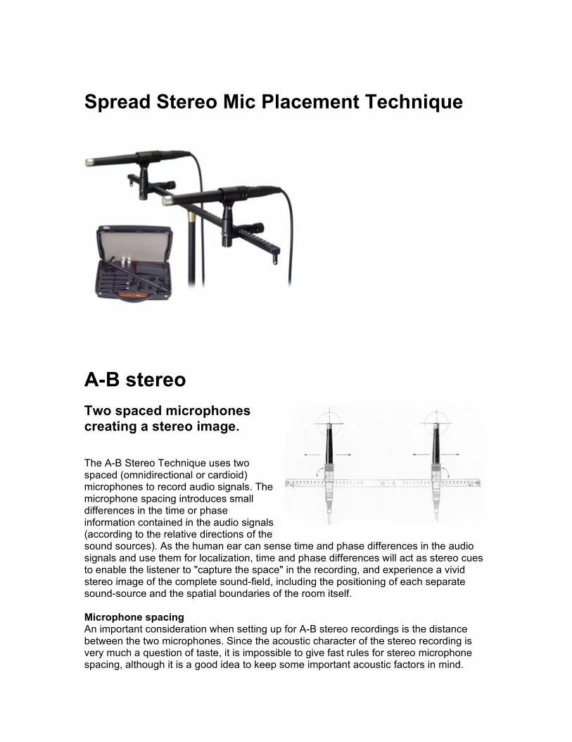
Spread Stereo Mic Placement Technique
A-B stereo Two spaced microphones creating a stereo image.
The A-B Stereo Technique uses two spaced (omnidirectional or cardioid) microphones to record audio signals. The microphone spacing introduces small differences in the time or phase information contained in the audio signals (according to the relative directions of the sound sources). As the human ear can sense time and phase differences in the audio signals and use them for localization, time and phase differences will act as stereo cues to enable the listener to "capture the space" in the recording, and experience a vivid stereo image of the complete sound-field, including the positioning of each separate sound-source and the spatial boundaries of the room itself. Microphone spacing An important consideration when setting up for A-B stereo recordings is the distance between the two microphones. Since the acoustic character of the stereo recording is very much a question of taste, it is impossible to give fast rules for stereo microphone spacing, although it is a good idea to keep some important acoustic factors in mind.
Since the stereo width of a recording is frequency-dependent, the deeper the tonal qualities you wish to reproduce in stereo, the wider your microphone spacing should be. Using a recommended microphone spacing of a quarter of the wavelength of the deepest tone, and taking into account the human ear's reduced ability to localize frequencies below 150Hz, leads to an optimal microphone spacing of between 40 and 60 cm. Smaller microphone spacings are often used close to sound-sources to prevent the sound image of a particular musical instrument from becoming "too wide" and unnatural. Spacings down to 17 to 20 cm are detectable by the human ear, as this distance is equivalent to the distance between the two ears themselves. It should also be noted, that an increase in microphone spacing will decrease the system's ability to reproduce the signals from sound-sources positioned directly between the microphones. This will also lead to a reduction in the quality of the stereo recording when it is played in mono. Distance between microphones and sound-source The ideal distance from the microphone pair to the sound-source not only depends on the type and size of the sound-source and on the surroundings in which the recording is to be made, but also on individual taste. The position from which the listener experiences the event - and hence the position from which the micro-phones record the event - should be chosen with care and feeling. Critical musical recordings, such as a full orchestra in a concert hall, are good examples of the importance of correct stereo microphone positioning. Here the microphones would typically be placed above or behind the conductor. And although most instruments project their sound in an upwards direction, the microphones should be placed high enough so that the individual musicians do not shadow each other. The mix of direct and diffuse sound in a recording is also of crucial importance, so much time can often be used establishing the optimum positioning of the microphones. It is here that the versatility of our A-B Stereo Kits comes into play. Using the different acoustical attachments for the microphones, the amount of ambience and the tonal color of the recording can be adjusted without adding any noise. The choice of floor and ceiling mounting of the boom can give you added flexibility when positioning the microphones. Omnidirectional microphones and A-B Stereo are often the preferred choice when the distance between microphone and the sound source is large. The reason is that omnidirectional microphones are able to capture the true low frequencies of the sound-source regardless of the distance, while directional microphones are influenced by the proximity effect. Directional microphones will therefore exhibit loss of low frequencies at larger distances. The DPA Wide Cardioid microphones are however designed with a richer bass response, making the bass loss at distances much less critical. Therefore these mics are a good alternative to omnis when a little directionality is preferred or needed. The sound color is very similar to our omnis.
Spaced Cardioids
Unlike the techniques discussed so far, spacing cardiod microphones apart and aiming them in toward the musicians is not a technique born of attempting to model the human listening experience. However, it can often prove more effective if a desire to include more of the room sound, or to achieve a flattering capture of the instruments, has led to a mic placement that is farther apart. If these events coincide with a narrow ensemble width to be recorded (such as a string quartet on a large stage, or a solo piano), then a more satisfying spread of the perceived stereo width can be created for the listener Spaced Omnis This technique uses two (or three for large ensembles) omni-directional microphones evenly placed in front of an ensemble. This technique is often blamed for producing phasing problems, but I have not often experienced that problem. Some cite a 3:1 rule which they say should be utilized. The 3 to 1 rule states that for every 1 unit of distance from the sound to the microphone should be 3 units of distance between microphones. (Example: microphones are 5 feet in front of the ensemble - the distance between the two microphones cannot be less than 15 feet - 7.5 feet each from the center line.) You must adapt to the situation, however, so such rules are only rough guidelines. Spaced omnis look like spaced cardioids, but the sound is quite different. Omnis must usually be placed much closer to the ensemble or there may be too much room sound. They have better balance of instruments in larger ensembles, but less of a distinct stereo separation than their cardioid counterparts. Omni Out-Riggers For large ensembles, all of the techniques mentioned above can be enhanced by adding a pair of omni out-riggers. These are placed some distance left and right of center, usually following the 3:1 rule cited above. .
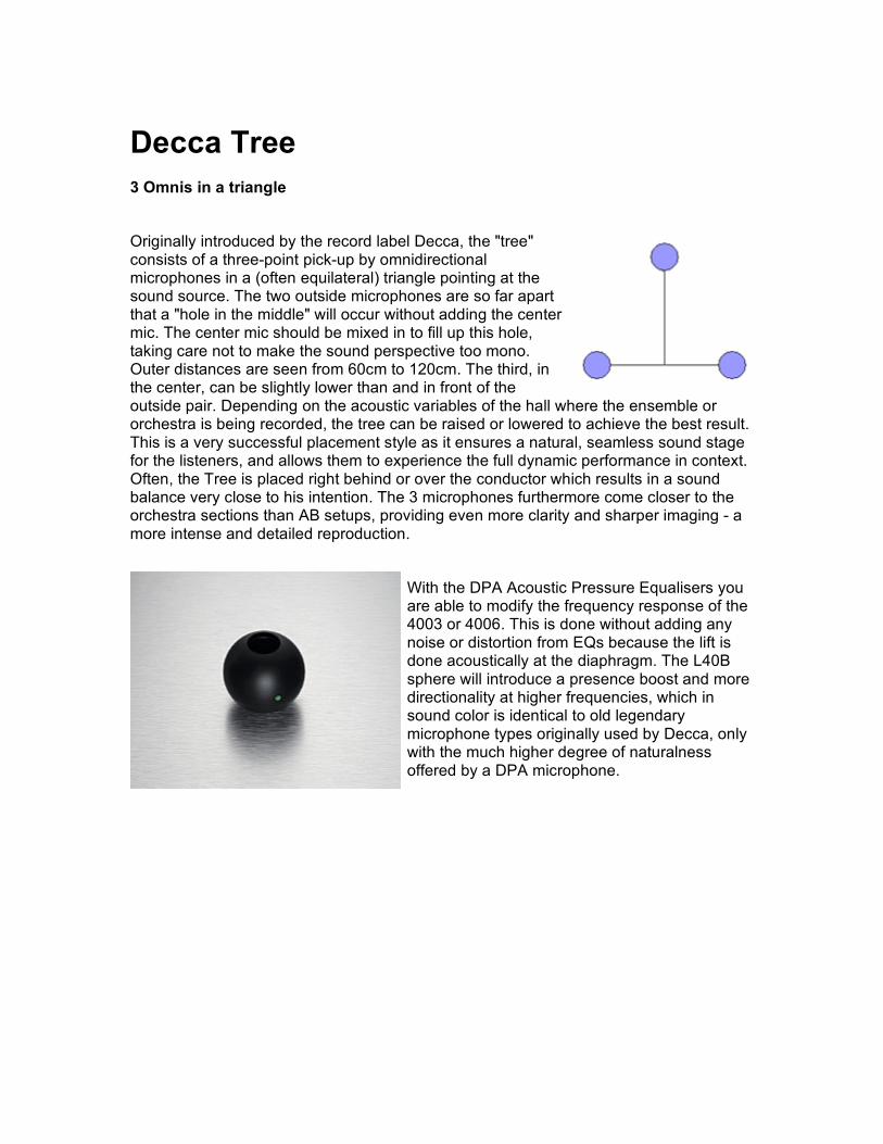
Decca Tree 3 Omnis in a triangle
Originally introduced by the record label Decca, the "tree" consists of a three-point pick-up by omnidirectional microphones in a (often equilateral) triangle pointing at the sound source. The two outside microphones are so far apart that a "hole in the middle" will occur without adding the center mic. The center mic should be mixed in to fill up this hole, taking care not to make the sound perspective too mono. Outer distances are seen from 60cm to 120cm. The third, in the center, can be slightly lower than and in front of the outside pair. Depending on the acoustic variables of the hall where the ensemble or orchestra is being recorded, the tree can be raised or lowered to achieve the best result. This is a very successful placement style as it ensures a natural, seamless sound stage for the listeners, and allows them to experience the full dynamic performance in context. Often, the Tree is placed right behind or over the conductor which results in a sound balance very close to his intention. The 3 microphones furthermore come closer to the orchestra sections than AB setups, providing even more clarity and sharper imaging - a more intense and detailed reproduction.
With the DPA Acoustic Pressure Equalisers you are able to modify the frequency response of the 4003 or 4006. This is done without adding any noise or distortion from EQs because the lift is done acoustically at the diaphragm. The L40B sphere will introduce a presence boost and more directionality at higher frequencies, which in sound color is identical to old legendary microphone types originally used by Decca, only with the much higher degree of naturalness offered by a DPA microphone.
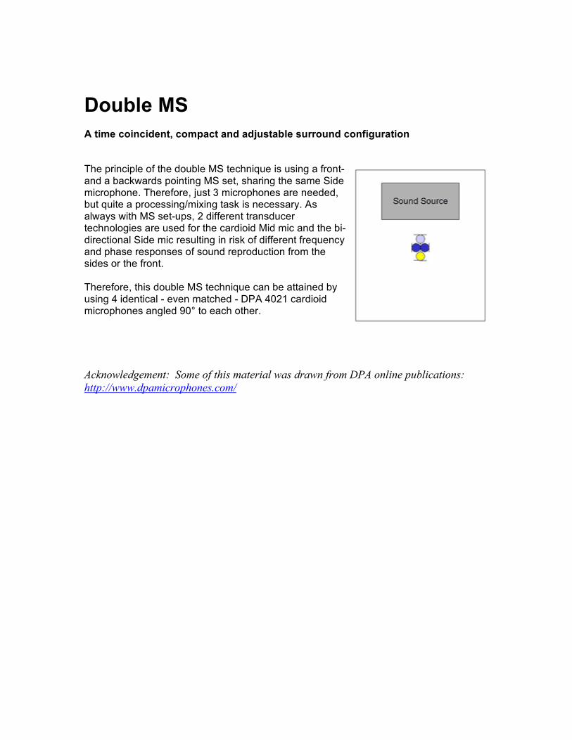
Double MS A time coincident, compact and adjustable surround configuration
The principle of the double MS technique is using a front- and a backwards pointing MS set, sharing the same Side microphone. Therefore, just 3 microphones are needed, but quite a processing/mixing task is necessary. As always with MS set-ups, 2 different transducer technologies are used for the cardioid Mid mic and the bi-directional Side mic resulting in risk of different frequency and phase responses of sound reproduction from the sides or the front. Therefore, this double MS technique can be attained by using 4 identical - even matched - DPA 4021 cardioid microphones angled 90° to each other. Acknowledgement: Some of this material was drawn from DPA online publications: http://www.dpamicrophones.com/
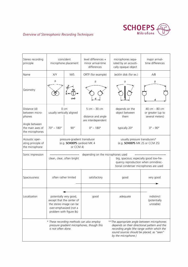
Overview of Stereophonic Recording Techniques
Stereo recording coincident level differences + microphones sepa- major arrival-principle microphone placement minor arrival-time rated by an acousti- time differences
differences cally opaque object
Name X/Y M/S ORTF (for example) Jecklin disk (for ex.) A/B
Geometry
Distance (d) 0 cm 5 cm – 30 cm depends on the 40 cm – 80 cmbetween micro- usually vertically aligned object between or greater (up tophones distance and angle them several meters)
are interdependentAngle betweenthe main axes of 70° – 180° 90° 0° – 180° typically 20° 0° – 90°the microphones
Acoustic oper- pressure-gradient transducer usually pressure transducers*ating principle of (e.g. SCHOEPS cardioid MK 4 (e.g. SCHOEPS MK 2S or CCM 2S)the microphone or CCM 4)
Sonic impression depending on the microphones usedclean, clear, often bright big, spacious; especially good low-fre-
quency reproduction when omnidirec-tional condenser microphones are used
Spaciousness often rather limited satisfactory good very good
Localization good adequate indistinct(potentiallyunstable)
* These recording methods can also employpressure gradient microphones, though thisis not often done.
**The appropriate angle between microphonesdepends on their directional pattern and therecording angle (the range within which thesound sources should be placed, as “seen“by the microphone.)
potentially very good,except that the center of the stereo image can beover-emphasized (not aproblem with figure 8s)