Embed Size (px)
Citation preview

75.5825.02 COLIBRI ONE 20160106 Page 1 of 4
COLIBRI ONE
5
1
3
4
2
Specifications are subject to changes without prior notice.Measured in specific conditions
TECHNICAL SPECIFICATIONS
DESCRIPTION
ENG
LISH
Unidirectional activation sensor*
1. main connector2. LED3. potentiometer for field size adjustment4. radar antenna (wide field)5. cover
Technology:Transmitter frequency: Transmitter radiated power:Transmitter power density:Detection mode:Min. detection speed:Supply voltage:Mains frequency:Max. power consumption:Output: Max. contact current: Max. contact voltage:Mounting height: Degree of protection:Temperature range:Dimensions:Tilt angles:Material:Weight:Cable lenght:Norm conformity:
microwave doppler radar24.150 GHz< 20 dBm EIRP< 5 mW/cm²motion2 in/s (measured in sensor axis)12 V to 24 V DC +30% / -10%50 to 60 Hz< 2 Wsolid-state-relay (free of potential change-over contact)100 mA35 V DC/ 24V ACfrom 6 ft to 10 ftIP54from -4 °F to + 131 °F3.15 in (W) x 2.36 in (H) x 2.17 in (D)0° to 90° vertical; -30° to +30° lateralABS & polycarbonate5 oz8 ftR&TTE 1999/5/EC; EMC 2004/108/EC
Other use of the device is outside the intended purpose and cannot be guaranteed by the manufacturer. The manufacturer cannot be held responsible for incorrect installations or inappropriate adjustments of the sensor.
Please keep for further useDesigned for color printing
For
prod
uct
vers
ion
0100
and
mor
e
*Not intended for pedestrian automatic doors
Page 2 of 4 75.5825.02 COLIBRI ONE 20160106
Before mounting After mounting
Avoid proximity to neon lamps or moving objects.
Do not cover the sensor.Avoid vibrations.Do not touch electronic parts.
Wall mounting Ceiling mounting
OPENING THE SENSOR
TIPS
APPLICATIONS
75.5825.02 COLIBRI ONE 20160106 Page 3 of 4
2
2 31
MIN MAX
1
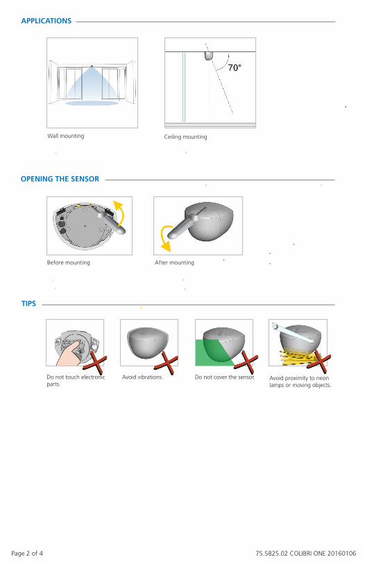
FIELD ADJUSTMENTS
Apply the mounting template.Drill 1 hole for the cable. Drill 2 holes for the screws.
Mount the sensor firmly.
AN
GLE
7 ft7 ft
Connect the cable and insert it through the hole.Connect the wires as follows:
SIZE
field size: max
vertical angle: 30°
7 ft 7 ft
MOUNTING & WIRING
13 ft x 6.5 ft (wide) 6.5 ft x 8 ft (narrow)available as accessory
WID
TH
7 ft 7 ft
RED - POWER SUPPLY 12-24 VBLACK - GROUND 0 VWHITE - COMGREEN - NO
Page 4 of 4 75.5825.02 COLIBRI ONE 20160106
1
123
1
12
1
1
©B
EA |
Ori
gina
l ins
truc
tion
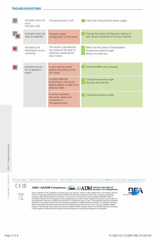
sTROUBLESHOOTING
Activation does not occur. The LED is OFF.
The sensor power is off. Check the wiring and the power supply.
Activation does not react as expected.
Activation and deactivation occurs constantly.
Improper output configuration on the sensor.
The sensor is disturbed by the closing of the door or vibrations caused by the door motion.
Activation occurs for no apparent reason.
It rains and the sensor detects the motion of the rain drops.
Change the output configuration setting on each sensor connected to the door operator.
Make sure the sensor is fixed properly.Increase the antenna angle.Reduce the field size.
Change the antenna angle.Decrease the field size.
Install the MRA (rain accessory).
In highly reflective environments, the sensor detects objects outside of its detection field.
In airlock vestibules, the sensor detects the movement of the opposite door.
Change the antenna angle.
Upon completion of the installation or service work, at a minimum, perform a daily safety check in accordance with theminimum inspection guidelines provided by AAADM. Provide each equipment owner with an owner’s manual that includes a daily safety checklist and contains, at a minimum, the information recommended by AAADM. Offer an information session with the equipment owner explaining how to perform daily inspections and point out the location of power/operation switches to disable the equipment if a compliance issue is noted. The equipment should be inspected annually in accordance with the minimum inspection guidelines. A safety check that includes, at a minimum, the items listed on the safety information label must be performed during each service call. If you are not an AAADM certified inspector, BEA strongly recommends you have an AAADM certified inspector perform an AAADM inspection and place a valid inspection sticker below the safety information label prior to putting the equipment into operation.
AAADM American Association of Automatic Door Manufactures
ANSI / AAADM Compliance
24/7 Tech Support: 1-800-407-4545 | Customer Service: 1-800-523-2462 | General Tech Questions: [email protected] | Tech Docs: www.beasensors.com