Embed Size (px)
Citation preview

QUALITY ASSURANCE/QUALITY CONTROL DOCUMENTATION SERIES
TITLE
COLLECTION OF OPTICAL MONITORING DATA (IMPROVE PROTOCOL)
TYPE
STANDARD OPERATING PROCEDURE
NUMBER
4300
DATE
MARCH 1993
AUTHORIZATIONS
TITLE NAME SIGNATURE
ORIGINATOR J. Carter Blandford
PROJECT MANAGER Mark Tigges
PROGRAM MANAGER David L. Dietrich
QA MANAGER Gloria S. Mercer
OTHER
REVISION HISTORY
REVISION NO.
CHANGE DESCRIPTION DATE AUTHORIZATIONS
Reviewed; no changes necessary. March 1994
Reviewed; no changes necessary. March 1995
0.1 Added responsibilities / minor text changes. June 1996
Reviewed; no changes necessary. June 1997
Reviewed; no changes necessary. June 1998
Reviewed; no changes necessary. June 1999
Reviewed; no changes necessary. June 2000
-- continued --

QUALITY ASSURANCE/QUALITY CONTROL DOCUMENTATION SERIES
TITLE
COLLECTION OF OPTICAL MONITORING DATA (IMPROVE PROTOCOL)
TYPE
STANDARD OPERATING PROCEDURE
NUMBER
4300
DATE
MARCH 1993
AUTHORIZATIONS
TITLE NAME SIGNATURE
ORIGINATOR J. Carter Blandford
PROJECT MANAGER Mark Tigges
PROGRAM MANAGER David L. Dietrich
QA MANAGER Gloria S. Mercer
OTHER
REVISION HISTORY
REVISION NO.
CHANGE DESCRIPTION DATE AUTHORIZATIONS
Reviewed; no changes necessary. June 2001
Reviewed; no changes necessary. June 2002
1.0 Delete strip charts/delete neph collection via DCP. December 2004

Number 4300 Revision 1.0 Date DEC 2004 Page i of i
TABLE OF CONTENTS Section Page 1.0 PURPOSE AND APPLICABILITY 1 2.0 RESPONSIBILITIES 2 2.1 Project Manager 2 2.2 Data Analyst 2 3.0 REQUIRED EQUIPMENT AND MATERIALS 3 4.0 METHODS 3 4.1 Optical Monitoring Station Configurations 4 4.1.1 Transmissometer Stations 4 4.1.2 Nephelometer Stations 5 4.2 Collection of Optical Monitoring Data 5 4.2.1 Collection of Transmissometer Data via DCP 5 4.2.2 Collection of Nephelometer Data via Telephone Modem 6 4.2.3 Collection of Nephelometer Data via Campbell Scientific Storage Module 7 5.0 REFERENCES 7

Number 4300 Revision 1.0 Date DEC 2004 Page 1 of 7
1.0 PURPOSE AND APPLICABILITY This standard operating procedure (SOP) outlines collection of optical visibility monitoring data from sites operated according to IMPROVE Protocol. Optical monitoring sites include those equipped with an Optec LPV transmissometer and/or Optec NGN nephelometer. The IMPROVE Program has partitioned visibility-related characteristics and measurements into three groups: optical, scene, and aerosol. This SOP pertains to the optical group and encompasses the following:
• Optical properties pertaining to the ability of the atmosphere to scatter or absorb light passing through it
• Physical properties of the atmosphere described by the atmospheric extinction
coefficient (bext), absorption coefficient (babs), scattering coefficient (bscat), and scattering phase function, an angular dependence of the scattering
• Optical characteristics integrating the effects of atmospheric aerosols and gases
• Optical extinction measurements made with transmissometers
• Optical scattering measurements made with nephelometers
Data are generally logged on-site by one of four datalogging approaches:
• Satellite data collection platforms (DCPs) (Handar 540/570)
• Campbell Scientific 21XL dataloggers
• Telephone modems
• Campbell Scientific storage modules This SOP serves as a guide to assure high quality data collection from transmissometer and nephelometer stations operated according to IMPROVE Protocol by:
• Assuring complete, error-free data downloads from Wallops Island or directly from individual monitoring stations via telephone modem.
• Assuring complete, error-free data downloads from sites with Campbell Scientific
dataloggers and backup Campbell Scientific storage modules.
• Processing data to reformat raw, downloaded data to Level-A validation.
• Reviewing data and examining error files for details regarding monitoring system performance, datalogger problems, or data acquisition problems.

Number 4300 Revision 1.0 Date DEC 2004 Page 2 of 7
Because most stations are remote, daily data review is critical to the identification and resolution of field problems. At sites with a DCP or Campbell Scientific datalogger and telephone modem, data are collected daily. At sites with a Campbell Scientific datalogger and storage module, or at sites where telephone line/telephone modem malfunction occurs, data are collected at approximately two-week intervals until the malfunction problem is resolved. Separate technical instructions (TIs) are developed for the following cases:
• TI 4300-4000 Data Collection via DCP (IMPROVE Protocol)
• TI 4300-4002 Nephelometer Data Collection via Telephone Modem (IMPROVE Protocol)
• TI 4300-4006 Nephelometer Data Collection via Campbell Scientific Data
Storage Module (IMPROVE Protocol)
• TI 4300-4023 Transmissometer Daily Compilation and Review of DCP-Collected Data (IMPROVE Protocol)
2.0 RESPONSIBILITIES 2.1 PROJECT MANAGER The project manager shall:
• Review data collection procedures with the data analyst to identify and correct problems.
• Review editing of instrument constants files with the data analyst.
• Coordinate with the NESDIS for allocation of DCP assignments.
2.2 DATA ANALYST The data analyst shall:
• Update all constants files pertaining to data collection and review with the project manager.
• Set up and initiate the data collection program(s).
• Check the status of the data collection and review data daily to assure the integrity of
the monitoring systems and to achieve complete, error-free data collection. • Update DCP platform description tables.

Number 4300 Revision 1.0 Date DEC 2004 Page 3 of 7
• Perform periodic data collection via data storage module for sites without DCP or
modem communication.
• Provide technical support to the site operator via telephone.
• Enter any information relating to the collection of the data and operation of the specific monitoring system into the site-specific Quality Assurance Database.
• Review Level-A files with the project manager to identify instrument problems.
3.0 REQUIRED EQUIPMENT AND MATERIALS All data collection occurs on IBM-PC compatible systems. Refer to the individual TIs for the monitoring system-specific computer system requirements. Required computer system components are as follows:
• IBM-PC Pentium class computer system with VGA and 80 megabyte hard disk and 64 megabytes of RAM
• Microsoft Windows98, or Windows2000 operating system
• Internal or external Hayes compatible modem configured for COM port #2
• Software for collection DCP data via Wallops Island
• Software for processing of data collected via DCP
• Software for telephone modem collection
• Campbell Scientific SC532 storage module interface
• NGN_PULL software Version 3.0 or later (ARS) • ASCII text editor • Wallops Island log book • Julian calendar
Information on the Campbell Scientific software is detailed in the Campbell Scientific PC208 Datalogger Support Software Instruction Manual. 4.0 METHODS This section includes two (2) major subsections: 4.1 Optical Monitoring Station Configurations 4.2 Collection of Optical Monitoring Data

Number 4300 Revision 1.0 Date DEC 2004 Page 4 of 7
These subsections describe the station configurations and data collection methods for each configuration. Collection of optical monitoring data is dependent on the configuration of individual sites. Transmissometer and nephelometer sites are generally configured differently. 4.1 OPTICAL MONITORING STATION CONFIGURATIONS Optical monitoring stations are configured based on the following:
• Transmissometer stations are generally configured with a DCP.
• Nephelometer stations are generally configured with a Campbell Scientific datalogger, telephone modem, and storage module.
4.1.1 Transmissometer Stations Transmissometers measure the ability of the atmosphere to transmit light. These measured light transmission properties can be represented in terms of the atmospheric extinction coefficient (bext). IMPROVE transmissometer sites generally include:
• A transmitter station with shelter, transmitter telescope, transmitter control box, and battery-backed power supply.
• A receiver station with shelter, receiver telescope, receiver computer, and battery-
backed power supply.
• A data collection platform (DCP).
• A collocated air temperature and relative humidity sensor (naturally aspirated).
• A solar powered operation (at some sites). The following data are collected via DCP from transmissometer sites operated according to IMPROVE Protocol:
• Ten-minute average raw transmissometer transmission values that are later converted to atmospheric extinction coefficient.
• Standard deviation of the 10 one-minute raw transmission values that make up the
10-minute average transmission value.
• Hourly, single reading ambient air temperature and relative humidity.
Number 4300 Revision 1.0 Date DEC 2004 Page 5 of 7
4.1.2 Nephelometer Stations Nephelometers measure the ability of the atmosphere to scatter light. These measured light scattering properties can be represented in terms of the atmospheric scattering coefficient (bscat). IMPROVE nephelometer sites generally include:
• An NGN-2 nephelometer mounted on a three-meter tower along with datalogger and power supply support system.
• A Campbell Scientific 21XL or 23XL datalogger.
• A Campbell Scientific storage module.
• An optional telephone modem.
• A collocated air temperature and relative humidity sensor (force aspirated).
• A solar powered operation (at some sites).
The following data are collected via telephone modem and storage module from nephelometer sites operated according to IMPROVE protocol:
• Five-minute nephelometer serial data stream
• Five-minute nephelometer analog channels A1 and A2
• Five-minute ambient air temperature and relative humidity
• Hourly codes summarizing the past hour’s operation of the nephelometer and support system
4.2 COLLECTION OF OPTICAL MONITORING DATA The method used to collect optical monitoring data depends on the type of site (transmissometer or nephelometer) and the site-specific configuration (telephone modem, storage module, DCP). The following subsections describe data collection procedures for the above listed station configurations. 4.2.1 Collection of Transmissometer Data via DCP Collection of transmissometer data via DCP is handled by Wallops.exe software. Specific procedures are detailed in TI 4300-4000, Data Collection via DCP (IMPROVE Protocol). Collection of transmissometer data via DCP includes:
• Updating the current list of sites in the site information file.
• Updating the next time to download data in the Wallops information file.

Number 4300 Revision 1.0 Date DEC 2004 Page 6 of 7
• Configuring the computer used for automatic data acquisition that downloads the data from Wallops the following day.
• Reviewing all downloaded data file for communication errors or indications of
monitoring, logging and data collection problems.
• Initiating manual data collection programs if automatic data collection failed.
• Executing the STRIP program which removes invalid characters and reformats the raw file.
• Executing the APPEND program to add the raw data to site-specific Level-A files.
• Resolving identified system inconsistencies according to TI 4110-3300,
Troubleshooting and Emergency Maintenance Procedures for Optec LPV-2 Transmissometer Systems (IMPROVE Protocol).
4.2.2 Collection of Nephelometer Data via Telephone Modem Collection of nephelometer data via telephone modem from sites configured with a Campbell Scientific datalogger is handled by the NGN_pull.exe software. Specific procedures are detailed in TI 4300-4002, Nephelometer Data Collection via Telephone Modem (IMPROVE Protocol). Collection of nephelometer data via modem includes the following:
• Updating the current list of sites.
• Updating the next time to download data.
• Initiating the automatic download timer.
• Polling each telephone modem station daily using the Campbell Scientific PC208 or LoggerNet program for all data since the last download.
• Dividing each downloaded data file into three parts:
- Nephelometer serial data, ambient temperature, and relative humidity - Nephelometer analog data, ambient temperature, and relative humidity - Hourly nephelometer status code and support system status code
• Reformatting and appending each site’s nephelometer serial data to site-specific Level-A plottable data files.
• Creating a daily nephelometer log file that contains a summary of the performance of
all of the sites downloaded.

Number 4300 Revision 1.0 Date DEC 2004 Page 7 of 7
• Resolving identified system inconsistencies according to TI 4100-3100, Routine Site Operator Maintenance Procedures for Optec NGN-2 Nephelometer Systems (IMPROVE Protocol).
4.2.3 Collection of Nephelometer Data via Campbell Scientific Storage Module Collection of nephelometer data via Campbell Scientific storage module is handled by the NGN_pull.exe software. Specific procedures are detailed in TI 4300-4006, Nephelometer Data Collection via Campbell Scientific Data Storage Module (IMPROVE Protocol). Collection of nephelometer data via storage module includes the following:
• Updating the current list of sites.
• Downloading data from the storage module using the Campbell Scientific PC208W or LoggerNet program into site-specific files compatible with data obtained via telephone modem.
• Dividing each downloaded data file into three parts:
- Nephelometer serial data, ambient temperature, and relative humidity - Nephelometer analog data, ambient temperature, and relative humidity - Hourly nephelometer status code and support system status code
• Reformatting and appending each site’s nephelometer serial data to site-specific plottable data files.
• Creating a nephelometer log file that contains a summary of the performance of all of
the sites downloaded.
• Resolving identified system inconsistencies according to TI 4100-3100. 5.0 REFERENCES Campbell Scientific, Inc., 1989, Campbell Scientific PC208 Datalogger Support Software Instruction Manual, February.

QUALITY ASSURANCE/QUALITY CONTROL DOCUMENTATION SERIES
TITLE
DATA COLLECTION VIA DCP (IMPROVE PROTOCOL)
TYPE
TECHNICAL INSTRUCTION
NUMBER
4300-4000
DATE
AUGUST 1993
AUTHORIZATIONS
TITLE NAME SIGNATURE
ORIGINATOR J. Carter Blandford
PROJECT MANAGER Mark Tigges
PROGRAM MANAGER David L. Dietrich
QA MANAGER Gloria S. Mercer
OTHER
REVISION HISTORY
REVISION NO.
CHANGE DESCRIPTION DATE AUTHORIZATIONS
0.1 Minor text modifications. June 1996
1.0 Changed software/ deleted Synergetics DCP. December 2004

Number 4300-4000 Revision 1.0 Date DEC 2004 Page i of ii
TABLE OF CONTENTS Section Page 1.0 PURPOSE AND APPLICABILITY 1 2.0 RESPONSIBILITIES 1 2.1 Project Manager 1 2.2 Data Analyst 1 3.0 REQUIRED EQUIPMENT AND MATERIALS 2 4.0 METHODS 2 4.1 General Information 2 4.1.1 GOES Satellite System 3 4.1.2 Data Collection Platforms (DCPs) 3 4.2 Data Collection Methods 4 4.2.1 Data Collection via Web Interface 4 4.2.2 Data Collection via Dial-Up 5 4.2.3 Data Collection via Telnet 5 4.2.4 Data Collection via Local Readout Ground Station (LRGS) Client Interface 6 4.3 Automatic Data Collection 6 4.4 Manual Data Collection 9 4.5 DCP Transmission Quality Check 12 4.6 Daily DCP Data Handling 15 4.7 Updating NESDIS Platform Description Tables (PDTs) 18 5.0 REFERENCES 18
LIST OF FIGURES Figure Page 4-1 Wallops Data Collection Properties Screen 7 4-2 Wallops Data Collection Security Screen 8 4-3 Wallops Data Collection Main Screen 9 4-4 Wallops Data Collection Manual Poll Screen 10

Number 4300-4000 Revision 1.0 Date DEC 2004 Page ii of ii
LIST OF FIGURES (CONTINUED) Figure Page 4-5 Wallops Data Collection Security Screen 11 4-6 Handar DCP Transmissometer Data Format (GALyyjjj.dat File) 13 4-7 DCP Transmission Quality Description 14 4-8 Example Siteinfo File for Daily Data Processing 16

Number 4300-4000 Revision 1.0 Date DEC 2004 Page 1 of 19
1.0 PURPOSE AND APPLICABILITY This technical instruction (TI) describes the collection of data logged by data collection platforms (DCPs) at transmissometer sites operated according to IMPROVE Protocol. The purpose of this TI is to assure quality data capture and minimize data loss by:
• Monitoring DCP operating parameters, including: transmission time, DCP battery voltage, signal strength, and transmission frequency deviation.
• Identifying and resolving problems affecting transmissometer systems, meteorological
sensors, data acquisition and control systems, and support equipment.
This TI, as referenced from Standard Operating Procedure (SOP) 4300, Collection of Optical Monitoring Data (IMPROVE Protocol), specifically describes:
• General information about data collection via DCP and data acquisition via the National Environmental Satellite Data and Information Service (NESDIS) downlink facility in Camp Springs, Maryland, via the satellite downlink station at Wallops Island, Virginia.
• Automatic and manual data acquisition procedures. • Daily handling of DCP data. • Verification of DCP transmission parameters. • Procedures for updating the NESDIS Platform Description Tables (PDTs). Troubleshooting procedures for DCPs are described in TI 4110-3300, Troubleshooting
and Emergency Maintenance Procedures for Optec LPV-2 Transmissometer Systems (IMPROVE Protocol). 2.0 RESPONSIBILITIES 2.1 PROJECT MANAGER The project manager shall:
• Coordinate with NESDIS for the allocation of DCP assignments for data collection.
• Review data acquired via DCP to detect and resolve problems. 2.2 DATA ANALYST The data analyst shall:
• Verify that automatic data collection via DCP is successful and perform manual data collection if unsuccessful.
• Review DCP-transmitted data to determine if the DCP and monitoring equipment are
functioning properly.

Number 4300-4000 Revision 1.0 Date DEC 2004 Page 2 of 19
• Provide technical support to the site operator via telephone to assure high quality data
capture from the DCP and monitoring equipment.
• Update NESDIS DCP platform description tables (PDTs) via telephone modem. 3.0 REQUIRED EQUIPMENT AND MATERIALS Equipment and materials generally required for data collection via DCP includes the following:
• Pentium class computer system with VGA and 80 megabyte hard disk and 64 megabytes of RAM
• Microsoft Windows98 or Windows2000 operating system
• Internal or external Hayes compatible modem configured for COM port #2 • Wallops automatic data collection software (Wallops.exe) (ARS) • User Interface Manual (UIM) for the Data Collection System Automatic Processing
System (DAPS), Version 1.1 • Wallops Island log book • Julian calendar • ASCII text editor such as Ultraedit.32
4.0 METHODS This section includes seven (7) major subsections: 4.1 General Information 4.2 Data Collection Methods 4.3 Automatic Data Collection 4.4 Manual Data Collection 4.5 DCP Transmission Quality Check 4.6 Daily DCP Data Handling 4.7 Updating NESDIS Platform Description Tables (PDTs) 4.1 GENERAL INFORMATION Data logged on data collection platforms (DCPs) are processed by several entities before being available for downloading via modem. Monitoring stations with DCPs undergo the following data downloading sequence:

Number 4300-4000 Revision 1.0 Date DEC 2004 Page 3 of 19
• The DCP logs transmissometer and/or meteorological data at pre-programmed intervals.
• At three-hour intervals, the DCP transmits the past three hours’ data and its internal
battery voltage to the GOES satellite.
• The GOES satellite retransmits the data to the NOAA/NESDIS downlink facility at Wallops Island, Virginia.
• The data are made available via the dissemination facility at Camp Springs, Maryland. • The data are downloaded via telephone modem to ARS.
4.1.1 GOES Satellite System The following general information summarizes how satellite data collection works: SATELLITE USE Use of the Geostationary Orbiting Earth Satellite (GOES) is free
to government agencies. Authorization and operation to use the satellite system is directed by the National Environmental Satellite Data and Information Service (NESDIS), a branch of the National Oceanic and Atmospheric Administration (NOAA).
DCP ASSIGNMENTS NESDIS assigns each DCP a one-minute data transmit time slot every three hours and a unique DCP identification code. Platform Description Tables (PDTs) describe the location and other operational parameters of each DCP. The PDTs must be updated via modem to reflect the status of all operational DCPs.
SATELLITE SYSTEM CAPACITY
Relay of data from DCPs to the downlink facility is a minor portion of the satellite’s job. Its primary function is to provide weather-related data and images to aid in weather forecasting. Each satellite is capable of utilizing 233 frequencies for a total capacity of over 12,000 DCPs per hour. The data transmission rate is 100 baud (bits per second). The majority of the DCPs in use throughout the United States help support early warning flood monitoring systems.
4.1.2 Data Collection Platforms (DCPs) DCPs manufactured by Handar are used at IMPROVE transmissometer monitoring sites. The DCPs have the following features:
• Low power, programmable, microprocessor-based system
• Analog sensor inputs

Number 4300-4000 Revision 1.0 Date DEC 2004 Page 4 of 19
• Real-time clock • GOES compatible radio transmitter
The dissemination facility makes the following data available via telephone modem a short time after the DCP transmits its data:
• Data logged by the DCP • Transmission date and time • DCP signal strength and deviation from the specified frequency • Quality of the DCP transmission
DCP transmission parameters are used to evaluate the performance of the DCP and to
resolve DCP-related problems quickly. 4.2 DATA COLLECTION METHODS Automatic data collection is completed internally by ARS computer software using one of the following techniques:
• Web interface • Dial-up • Telnet • Local Readout Ground Station (LRGS) Client Interface
4.2.1 Data Collection via Web Interface The Web interface method collects data from the DCS (Data Collection System) Web site at http://dcs.noaa.gov. This is accomplished using a Perl script that is called directly from Visual Basic using the appropriate command line arguments. Web site pages include:
• http://dcs.noaa.gov - initial page • http://dcs.noaa.gov/javascriptform.html - cookie information for security • http://dcs.noaa.gov/UserIE.asp - parameter selection and output generation page
Number 4300-4000 Revision 1.0 Date DEC 2004 Page 5 of 19
This data collection may also be manually initiated by performing the following:
• Visit http://dcs.noaa.gov and click on DAPS/DCS Beta Site. • Click User's Pages from the frame on the left. • Enter the necessary cookie information into the java script form and click GOTO
DAPS User Section or click cancel if cookie information has already been established.
• At the DCS/DAPS Beta Site Menu, select D/L Msg's by PDT# from the Download
Platform Data section and click GO. • If necessary, change polling parameters and click Send. • If the operation is successful, data should appear on a results Web page.
To disable the Web interface collection method, leave the Perl Path field on the Properties tab blank. 4.2.2 Data Collection via Dial-Up Dial-Up access utilizes the DCS dial-up connection to collect data from Wallops. HyperAccess is called directly from Visual Basic using OLE automation to access the HyperAccess phonebook entry: C:\Program Files\HAWin32\My Files\ WallopsDialUp.HAW. Dial-up access currently requires the following settings:
• Data Bits – 7 • Parity – even • Stop Bits – 1 • Terminal Emulation – TTY
Further information can be found at http://dcs.noaa.gov/dapsuser.htm. 4.2.3 Data Collection via Telnet Telnet would be the preferred method of data collection, but at this time the ARS firewall port 23 is not open and telnet is not available. Telnet requires that this port be open. Telnet access utilizes the DCS telnet site 128.154.62.173 to collect data from Wallops. HyperAccess is called directly from Visual Basic using OLE automation to access the HyperAccess phonebook entry: C:\Program Files\HAWin32\My Files\ WallopsTelnet.HAW. Telnet access currently requires the following settings:
• Terminal Emulation - TTY Further information can be found at http://dcs.noaa.gov/dapsuser.htm.

Number 4300-4000 Revision 1.0 Date DEC 2004 Page 6 of 19
4.2.4 Data Collection via Local Readout Ground Station (LRGS) Client Interface The Local Readout Ground Station Client Interface is a java program that is run on the local workstation to provide a graphical user interface to collect data from the Wallops system. This program requires Windows NT or higher. Further information can be found at http://cdadata.wcda.noaa.gov. 4.3 AUTOMATIC DATA COLLECTION The Wallops data collection software, configured for auto mode, will attempt to collect data beginning each day at the time specified in the Daily Poll Time field on the Properties tab of the software. The first attempt will be made using the Internet (Web interface) and the second attempt will be made using dial-up (with redial setup for backup telephone numbers, etc.). If both of these attempts are unsuccessful, the process will repeat each minute until successful.
The following detailed procedures describe automatic data collection of DCP data:
LOG ONTO NETWORK Log onto the ARS computer network Wallops data collection
workstation using your assigned username and password.
EXECUTE SOFTWARE The Wallops automatic data collection program will begin. To manually launch the data collection program, select the desktop shortcut to F:\ARS_soft\programs\wallops.exe. In the automatic mode, four tabs should appear in the user interface: 1) Main, 2) Manual Poll, 3) Properties, and 4) Security.
CHECK PROPERTIES
Fields on the Properties tab include (refer to Figure 4-1): • Network or Local – the program is able to run exclusively on the
local workstation or rely on network drives and directories. The default is network.
• Daily Poll Time (in local time zone) – time the daily automatic
collection program is scheduled to begin. • DPS Start Time – default start time for manual data collection. • Default Output Path – output directory for data collected during
automatic collection. Data collection properties are stored in a network and local file (network: O:\trans\Wallops\Wallops.ini and local: C:\Documents and Settings\administrator\Application Data\ARS\Wallops.ini). Changes may be made on the Wallops Data Collection interface; after making changes, select the Update Properties button and changes to the .ini file will take effect.

Number 4300-4000 Revision 1.0 Date DEC 2004 Page 7 of 19
CHECK PROPERTIES (continued)
. Figure 4-1. Wallops Data Collection Properties Screen.
CHECK SECURITY
Fields on the Security tab include (refer to Figure 4-2): • DAPS Firewall Username – DAPS firewall user name • DAPS Firewall Password – DAPS firewall password • DAPS Username – DAPS username • DAPS Password – DAPS password
Security properties are stored in a network and local file (network: O:\trans\Wallops\Wallops.ini and local: C:\Documents and Settings\ administrator\Application Data\ARS\Wallops.ini). Changes may be made on the Wallops Data Collection interface; after making changes, select the Update Properties button and changes to the .ini file will take effect.

Number 4300-4000 Revision 1.0 Date DEC 2004 Page 8 of 19
CHECK SECURITY (continued)
Figure 4-2. Wallops Data Collection Security Screen.
VERIFY SUCCESS
Fields on the Main tab include (refer to Figure 4-3): Check the Last Successful Automatic Poll window to determine when the last successful data collection occurred and/or check the Processing Status window to determine if automatic data collection yielded success or failure. Press the PAUSE/RESUME button to turn data collection off and on.

Number 4300-4000 Revision 1.0 Date DEC 2004 Page 9 of 19
VERIFY SUCCESS (continued)
Figure 4-3. Wallops Data Collection Main Screen.
4.4 MANUAL DATA COLLECTION Data may be collected manually via telephone modem from the data dissemination facility. The following procedures detail manual data collection of DCP data: LOG ONTO NETWORK Log onto the ARS computer network Wallops data collection
workstation or any workstation in the Data Collection Center using your assigned username and password.
EXECUTE SOFTWARE The Wallops manual data collection program will begin. To manually launch Wallops data collection, select the desktop shortcut to F:\ARS_soft\programs\wallops.exe. In the manual mode, three tabs should appear in the user interface: 1) Manual Poll, 2) Properties, and 3) Security. Manual mode will require that parameters be established on the Manual Poll tab and will only poll for the selected polling method once the GO! button has been pushed.

Number 4300-4000 Revision 1.0 Date DEC 2004 Page 10 of 19
CHECK DATES, TIMES, METHODS, AND FILE PATHS
Fields on the Manual Poll tab include (refer to Figure 4-4): • Start Julian Day - start Julian date for manual data collection • End Date – end Julian date for manual data collection • Start Time - start time (GMT) for manual data collection • End Time – end time (GMT) for manual data collection • Web Interface or Dial-Up – choose Web interface or dial-up
for manual collection • Output File - output directory for data collected during
manual collection Set each of the manual data collection fields. To save changes to the manual Output File path, press the Set Path button. When done with configuration, press GO! to begin data collection.
Figure 4-4. Wallops Data Collection Manual Poll Screen.

Number 4300-4000 Revision 1.0 Date DEC 2004 Page 11 of 19
CHECK SECURITY Fields on the Security tab include (refer to Figure 4-5): • DAPS Firewall Username – DAPS firewall user name • DAPS Firewall Password – DAPS firewall password • DAPS Username – DAPS username • DAPS Password – DAPS password Security properties are stored in a network and local file (network: O:\trans\Wallops\Wallops.ini and local: C:\Documents and Settings\ administrator\Application Data\ARS\ Wallops.ini). Changes may be made on the Wallops Data Collection interface; after making changes, select the Update Properties button and changes to the .ini file will take effect.
Figure 4-5. Wallops Data Collection Security Screen.
VERIFY SUCCESS Check the Processing Status to determine if manual data
collection yielded success or failure.
Number 4300-4000 Revision 1.0 Date DEC 2004 Page 12 of 19
4.5 DCP TRANSMISSION QUALITY CHECK The data satellite downlink facility analyzes DCP transmissions for transmission strength and quality. The data analyst should check the downloaded data file for correct DCP operation as follows:
• Edit the downloaded data file • Check the messages and news information at the beginning of the file • Check each DCP data transmission regarding:
- DCP address
- Transmission time (year, Julian day, hour, minute, and second)
- Failure code
- DAMS data quality measurements (signal strength, frequency deviation, modulation index, and modulation quality)
- DCP transmission channel
- Message length
- Transmissometer data transmission format The following procedures detail the DCP transmission quality check: EDIT THE FILE Edit the downloaded file using any ASCII editor such as
Ultraedit.32. Go to the downloaded data file, usually of the format GALyyjjj.dat, where yy is the year, and jjj is the Julian date.
CHECK MESSAGES AND NEWS
The downloaded data file may contain information about data dissemination processes, solar eclipses, data archiving, etc. This information may provide clues to failed DCP transmissions or poor quality data.
CHECK DCP TRANSMISSIONS
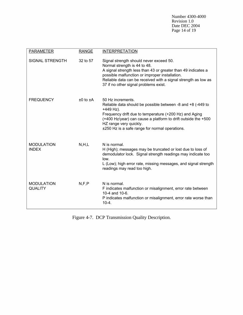
Each DCP transmission has associated quality assurance information added to the downloaded data file. Figure 4-6 details the information for a Handar DCP. Figure 4-7 details the ranges of acceptable values for the DCP transmission information. If any parameter is out of range, refer to TI 4110-3300, Troubleshooting and Emergency Maintenance Procedures for Optec LPV-2 Transmissometer Systems (IMPROVE Protocol).
CHECK DATA FORMAT Figure 4-6 details the data transmission formats for transmissometer stations. If the transmitted data are not in the correct format, refer to TI 4110-3000.

Number 4300-4000 Revision 1.0 Date DEC 2004 Page 13 of 19
Example Data Row Description FA42914E93085112729G38+1HN009EFF00143 Identification and quality 0501 001 004 0137 090 000 000 000 00.0 13.8 First hourly data 0495 000 004 0138 088 000 000 000 00.0 13.8 Second hourly data 0496 001 003 0138 086 000 000 000 00.0 13.8 Third hourly data 1 2 3 4 5 6 7 8 9 10 Data column Column Description 1 Raw transmission average (counts) 2 Receiver computer toggle 3 Standard deviation of the raw transmission (counts) 4 Ambient temperature (°F) (+ 100) 5 Ambient relative humidity (%) 6-9 Not used 10 DCP battery voltage (VDC) Identification and transmission quality: Characters Example Description 1-8 FA42914E DCP identification 9-10 93 Year of transmission 11-13 085 Julian date of transmission 14-15 11 Hour of transmission 16-17 27 Minute of transmission 18-19 29 Second of transmission 20 G Failure code 21-22 38 Signal strength 23-24 +1 Modulation frequency deviation from normal 25 H Modulation quality 26 N Modulation index 27-29 009 Satellite channel 30 E Satellite (East or West) 31-32 FF IFPD (Intermediate Frequency Presence Detector) 33-37 00143 Message length
Figure 4-6. Handar DCP Transmissometer Data Format (GALyyjjj.dat File).
Number 4300-4000 Revision 1.0 Date DEC 2004 Page 14 of 19
PARAMETER RANGE INTERPRETATION
SIGNAL STRENGTH 32 to 57 Signal strength should never exceed 50. Normal strength is 44 to 48. A signal strength less than 43 or greater than 49 indicates a possible malfunction or improper installation. Reliable data can be received with a signal strength as low as 37 if no other signal problems exist.
FREQUENCY ±0 to ±A 50 Hz increments. Reliable data should be possible between -8 and +8 (-449 to +449 Hz). Frequency drift due to temperature (+200 Hz) and Aging (+400 Hz/year) can cause a platform to drift outside the +500 HZ range very quickly. ±250 Hz is a safe range for normal operations.
MODULATION INDEX
N,H,L N is normal. H (High); messages may be truncated or lost due to loss of demodulator lock. Signal strength readings may indicate too low. L (Low); high error rate, missing messages, and signal strength readings may read too high.
MODULATION QUALITY
N,F,P N is normal. F indicates malfunction or misalignment, error rate between 10-4 and 10-6. P indicates malfunction or misalignment, error rate worse than 10-4.
Figure 4-7. DCP Transmission Quality Description.

Number 4300-4000 Revision 1.0 Date DEC 2004 Page 15 of 19
4.6 DAILY DCP DATA HANDLING Daily DCP data handling includes automatic removal of invalid characters from the downloaded file and reformatting the downloaded file into a form usable by processing software. Specifically, DCP data handling includes:
• Updating the Siteinfo file. • Running the Strip program to remove invalid characters and reformat the downloaded
data file. • Examining the stripped file to determine the beginning and ending dates and times for
the interval of the file. The file name is GALyyjjj.tmp (where yy is the year and jjj is the Julian date).
• Recording the interval in the Wallops Island log book. • Examining the Error.dat file for incomplete transmissions. • Examining the Message.dat file for information included in the header of the
downloaded data file. (This file is only available through the dial-up data collection method).
EDIT AND UPDATE THE SITEINFO FILE
The site list information file, Siteinfo, includes information for the current transmissometer sites, including associated DCP ID, site abbreviation, GMT time offset to Local Standard Time (LST), and number of lines in the DCP transmission. The information in the Siteinfo file is used by the Strip and Append programs to define which DCP IDs are valid and to which site they are assigned. The Siteinfo file is located in the O:\trans\Wallops directory. The Siteinfo file must be updated to reflect changes to DCP-related site configurations. The following procedures describe editing of the Siteinfo file: • Edit the Siteinfo file using any ASCII editor such as
Ultraedit.32. The file format for Siteinfo is detailed in Figure 4-8.
• Add, delete, or change the lines in the file to reflect the
currently operating DCP-equipped stations. • Update the number of stations in the first line of Siteinfo to
reflect the number of stations listed in the file. • Save the Siteinfo file.

Number 4300-4000 Revision 1.0 Date DEC 2004 Page 16 of 19
Line Number Siteinfo File Contents 1 14 2 FA42914E,ACAD1H,4,3,ACADIA,OK,BEXT 3 FA4315A0,BADL1H,7,3,BADLANDS,OK,BEXT 4 FA4380C2,BAND1T,7,3,BANDELIER,OK,BEXT 5 FA4356AA,BIBE1H,6,3,BIG BEND,OK,BEXT 6 FA43A62E,BRID1H,7,3,BRIDGER,OK,BEXT 7 FA44220E,BRME1O,7,6,BRYCE CANYON,OK,NONE 8 FA44F466,CANY1H,7,3,CANYONLANDS,OK,BEXT 9 FA450618,CHIR1H,7,3,CHIRICAHUA,OK,BEXT 10 FA441794,GLAC1T,7,3,GLACIER,OK,BEXT 11 FA44E710,GRBA1H,8,3,GREAT BASIN,OK,BEXT 12 FA44D28A,GRCA1H,7,3,GRAND CANYON (SOUTH RIM),OK,BEXT 13 FA43F652,GRCW1H,7,3,GRAND CANYON (IN-CANYON),OK,BEXT 14 FA42F4A8,GRCM1M,7,11,GRAND CANYON MET,OK,NONE 15 FA437046,GUMO1H,6,3,GUADALUPE,OK,BEXT Line Number Descriptions 1 Number of sites described in this file 2 One line per site in the format described below Siteinfo Line Format DCP ID, site abbreviation and type, GMT time offset to LST, number of data lines per transmission, expanded name, status, type of data Field Description DCP ID 8-Character DCP identification tag. Site abbreviation and type 5-Character site abbreviation plus 1-character site type:
T = Transmissometer with Handar AT/RH sensor H = Transmissometer with Rotronics AT/RH sensor O = Bryce Canyon meteorological station M = Grand Canyon Tonto Plateau meteorological station
GMT time offset to LST Number of hours between Greenwich Mean Time (GMT) (the time
programmed into the DCP) and Local Standard Time (LST) (the time used to tag the data).
Number of data lines Each transmission should contain x number of data lines (not counting the
DCP ID header line). Expanded name This appears at the top of the raw data plots. Status OK or TEST to indicate whether the site is active or not. (OK = active, TEST = not active). Type of data For transmissometers, this is always BEXT, otherwise it is NONE. There should be one line for every DCP-configured site.
Figure 4-8. Example Siteinfo File for Daily Data Processing.

Number 4300-4000 Revision 1.0 Date DEC 2004 Page 17 of 19
EXECUTE STRIP The Strip program performs the following functions:
• Strips the downloaded data file of invalid characters. • Saves the logon and file header information in the
Message.dat file. • Saves incomplete transmissions in the Error.dat file. • Reformats the downloaded data file and sorts it by
transmission date and time (GALyyjjj.tmp file).
The downloaded data file must be run through Strip before daily data processing of transmissometer data can proceed. The Strip program is started by clicking on Strip within the LPV_seas.exe software program. Refer to TI 4300-4023, Transmissometer Daily Compilation and Review of DCP-Collected Data (IMPROVE Protocol).
RECORD START AND END TIMES
The stripped downloaded data file is sorted by transmission data and time. Examine the first and last transmissions in the GALyyjjj.tmp file and record them in the Wallops Island logbook.
EXAMPLE ERROR FILE
The Error.dat file in O:\trans\Wallops contains incomplete transmissions from the downloaded data file. Examine this file for error messages. If error(s) exist, the data file contains incomplete transmissions that must be corrected. The following procedures describe how to edit the GALyyjjj.dat file that generated an error in the Error.dat file: • Edit the GALyyjjj.dat file using any ASCII editor such as
Ultraedit.32. • Each transmissometer data transmission format contains three
lines of data following the header line as follows: FA44D28A93110141630G51-1NN014WFF00143 0473 000 004 0136 026 000 000 000 00.0 12.8 0470 001 005 0135 026 000 000 000 00.0 12.8 0470 000 003 0139 023 000 000 000 00.0 13.1 • Add, delete, or change the lines in the data file so that the
transmission format is complete. For example: the error is “FA44D28A93110011630, 2 lines does not = 3 lines,” and the transmission in the GALyyjjj.dat file looks like –

Number 4300-4000 Revision 1.0 Date DEC 2004 Page 18 of 19
EXAMPLE ERROR FILE (continued)
FA44D28A93110141630G51-1NN014WFF00143 0473 000 004 0136 026 000 000 000 00.0 12.8 0470 001 005 0135 026 000 000 000 00.0 12.8 Add a third line with 999’s so the transmission looks like – FA44D28A93110141630G1-1NN014WFF00143 0473 000 004 0136 026 000 000 000 00.0 12.8 0470 001 005 0135 026 000 000 000 00.0 12.8 9999 999 999 9999 999 999 999 999 9999 9999 Once errors are corrected, run Strip again and reexamine the
Error.dat file. Do not proceed to the next processing stage until the Error.dat file is free of errors. (See TI 4300-4023, Transmissometer Daily Compilation and Review of DCP-Collected Data (IMPROVE Protocol).
EXAMINE MESSAGE FILE The Message.dat file in O:\trans\Wallops contains the header
information from the downloaded data file. (This file is only available through the dial-up data collection method).
PERFORM DAILY DATA COMPILATION AND REVIEW
Once the primary data collection is complete, the next phase in daily data handling includes compilation and review of the collected data. Refer to TI 4300-4023, Transmissometer Daily Compilation and Review of DCP-Collected Data (IMPROVE Protocol)
4.6 UPDATING NESDIS PLATFORM DESCRIPTION TABLES (PDTS) The NESDIS program information tables must be updated when any change in an operational parameter (location, etc.) occurs. Figure 4-9 details the contents of a typical PDT. Refer to the User Interface Manual (UIM) for the Data Collection System Automatic Processing System (DAPS), Version 1.1 for details on updating PDTs. 5.0 REFERENCES Integral Systems, Inc., 1990, User Interface Manual (UIM) for the Data Collection System Automatic Processing System (DAPS), Version 1.1, September.

Number 4300-4000 Revision 1.0 Date DEC 2004 Page 19 of 19
PARAMETER DESCRIPTION OWNER_ID Owner user ID (must be in UDT) PRIME_TYPE Primary Type: S: Self-timed I: Interrogate R: Random D: Dual PRIME_CHAN Primary CHANNEL: 1 - 266 (must be in CDT) PRIME_SCD Primary GOES spacecraft assigned: E: East, W: West SECND_ADDR Secondary address or Null SECND_TYPE Secondary type: R: Random I: Interrogate, or Null Note: Valid PRIME/SECND types are S/I, S/R SECND_CHAN Secondary channel: 0 - 266 (must be in CDT if > 0) SECND_SCID Secondary GOES spacecraft assigned: E: East, W: West, or Null TRIGGER_MODE Trigger mode: S: Special, T: Test, or Null Note: if not Null then: (a) PRIME_TYPE must be R (b) SECND_ADDR (trigger id) required FIRST_XMT
Time of first interrogation for I type platforms in HMMSS format
XMT_PERIOD Time period between transmissions (S/D) Time period between interrogations (I) in HHMMSS format XMT_WINDOW Maximum transmission window size in MMSS (S/D) XMT_RATE Data transmission rate in bps (100/300/1200) MAX_RETRIES Maximum number of interrogation retries (I) DATA_FORMAT DCPRS data format: A: ASCII, B: Binary PRIME_PREAMBLE DCPRS preamble type: L: Long, S: Short SECND_PREAMBLE DCPRS preamble type: L: Long, S: Short, or Null LOC_CODE Three-character location code LOC_REGION Location category: A: United States, B: Canada, C: South America, O: Other LOC_NAME Location name (31 characters) LATITUDE Latitude in DDMMSS LONGITUDE Longitude in DDMMSS MIN_ELEVATION Minimum elevation angle of platform (in DD) CATEGORY Platform category: Fixed: Fixed-buoy, D: Drifting-buoy A: Aircraft, S: Ship B: Balloon, L: Land-based O: Other
Figure 4-9. DCP Platform Description Table (PDT) Description.

QUALITY ASSURANCE/QUALITY CONTROL DOCUMENTATION SERIES
TITLE
TRANSMISSOMETER DAILY COMPILATION AND REVIEW OF DCP-COLLECTED DATA (IMPROVE PROTOCOL)
TYPE
TECHNICAL INSTRUCTION
NUMBER
4300-4023
DATE
JULY 1993
AUTHORIZATIONS
TITLE NAME SIGNATURE
ORIGINATOR J. Carter Blandford
PROJECT MANAGER Mark Tigges
PROGRAM MANAGER David L. Dietrich
QA MANAGER Gloria S. Mercer
OTHER
REVISION HISTORY
REVISION NO.
CHANGE DESCRIPTION DATE AUTHORIZATIONS
0.1 Minor text modifications. June 1996
1.0 Changed directory locations, updated file keys December 2004

Number 4300-4023 Revision 1.0 Date DEC 2004 Page i of i
TABLE OF CONTENTS Section Page 1.0 PURPOSE AND APPLICABILITY 1 2.0 RESPONSIBILITIES 1 2.1 Project Manager 1 2.2 Data Analyst 1 3.0 REQUIRED EQUIPMENT AND MATERIALS 2 4.0 METHODS 2
LIST OF FIGURES
Figure Page 4-1 Example Siteinfo File and Description 4 4-2 Example Lamp Calibration File (xxxxx_L) 5 4-3 Example Tprocess.con File and Description 7 4-4 Software Screen Showing Appending Daily Data 8 4-5 Example Level-A Transmissometer File and Description (xxxxx_T.yyq Files) 9

Number 4300-4023 Revision 1.0 Date DEC 2004 Page 1 of 9
1.0 PURPOSE AND APPLICABILITY This technical instruction (TI) describes the daily compilation and review of DCP transmissometer and meteorological data from an Optec LPV transmissometer station operated according to IMPROVE Protocol. The primary purpose of daily compilation and review is to assure quality data capture and minimize data loss by:
• Extracting each site’s DCP transmissometer and meteorological data from the stripped daily data file downloaded from the NOAA/NESS data dissemination facility at Wallops Island, Virginia.
• Reformatting and appending the data to site-specific Level-A validation data files.
Because most stations are remote and have limited operator visits, early identification of system problems during daily data review is critical to initiating timely corrective actions that minimize data loss. This TI, as referenced from Standard Operating Procedure (SOP) 4300, Collection of Optical Monitoring Data (IMPROVE Protocol), specifically describes:
• Updating the following transmissometer constants files:
- Siteinfo, the DCP site description file. - xxxxx_L, the site-specific lamp calibration files. - Tprocess.con, the data processing control file.
• Operation of the Level-A processing program (LPV_seas.exe). • File formats of the transmissometer constants files and site-specific Level-A validation
data files. 2.0 RESPONSIBILITIES 2.1 PROJECT MANAGER The project manager shall:
• Review editing of transmissometer constants files with the data analyst.
• Review the daily transmissometer data compilation to Level-A files with the data analyst to assure timely and accurate daily processing.
2.2 DATA ANALYST The data analyst shall:
• Update all transmissometer constants files and review with the project manager.
• Manually initiate the daily data append program.
• Review the Level-A files to identify instrument problems with the project manager.

Number 4300-4023 Revision 1.0 Date DEC 2004 Page 2 of 9
3.0 REQUIRED EQUIPMENT AND MATERIALS Transmissometer data compilation procedures require the following computer hardware and software:
• Pentium class computer system with VGA and 80 megabyte hard disk and 64 megabytes of RAM
• Microsoft Windows98 or Windows2000 operating system
• Internal or external Hayes compatible modem configured for COM port #2
• Transmissometer data validation (LPV_seas.exe) software (ARS)
• ASCII text editor such as Ultraedit.32
4.0 METHODS Transmissometer data collected via DCP are processed daily to reformat and append the data to site-specific Level-A validation data files. The Level-A files may then be reviewed and plotted. Review of transmissometer data is detailed in TI 4400-5000, Transmissometer Data Reduction and Validation (IMPROVE Protocol). Automatic and manual collection of DCP data is handled in accordance with TI 4300-4000, Data Collection via DCP (IMPROVE Protocol). Daily processing of DCP transmissometer data consists of the following steps:
• Updating the Siteinfo file containing the list of currently operating sites.
• Updating the site-specific lamp calibration files, xxxxx_L, (where xxxxx is the site abbreviation).
• Updating the Tprocess.con site information file.
• Executing the Level-A processing program (LPV_seas.exe).
The following procedures detail the steps for daily processing of transmissometer data:
LOG ONTO NETWORK Log onto the ARS computer network on the transmissometer data handling computer using your assigned username and password.
UPDATE THE SITEINFO FILE
The site list information file, Siteinfo, includes the currently operating transmissometer sites with their associated DCP ID, site abbreviation, GMT time offset to Local Standard Time (LST), and number of lines in the DCP transmission. Information in the Siteinfo file is used by the LPV_seas.exe program to define

Number 4300-4023 Revision 1.0 Date DEC 2004 Page 3 of 9
UPDATE THE SITEINFO FILE (continued)
which DCP IDs are valid and to which site they are assigned. The Siteinfo file is located on the network in the O:\Trans\Wallops directory. It must be updated to reflect changes to DCP-related site configurations. The following procedures describe editing of the Siteinfo file: • Edit the Siteinfo file using any ASCII editor such as
Ultraedit.32. The file format for Siteinfo is detailed in Figure 4-1. • Add, delete, or change the lines in the file to reflect the
currently operating DCP-equipped stations. • Update the number of stations on the first line of the file to
reflect the number of stations listed in the file. • Save the Siteinfo file.
UPDATE THE SITE-SPECIFIC LAMP FILES
The site-specific lamp calibration files include the following site-specific information: • Lamp installation and removal dates and times • Lamp serial numbers and calibration numbers • Path distance and Rayleigh coefficient • Lamp calibration curve set information The information in the transmissometer lamp files is required to calculate the atmospheric extinction coefficient (bext) from the raw transmission values collected via DCP. The lamp files must be edited with the most current information available regarding lamps. Each site has its own lamp file with file name xxxxx_L, where xxxxx is the site abbreviation. The following procedures detail the steps for editing individual lamp files: • Locate lamp files on the network in the O:\Trans\Site.con
directory. • Edit an individual lamp file using any ASCII editor. The file
format for lamp files is detailed in Figure 4-2. • Edit the fields in the lamp file to reflect current information
regarding the site. Commas must be included between fields. • Save the lamp file.

Number 4300-4023 Revision 1.0 Date DEC 2004 Page 4 of 9
Line Siteinfo File Contents 1 14 2 FA42914E,ACAD1H,4,3,ACADIA,OK,BEXT 3 FA4315A0,BADL1H,7,3,BADLANDS,OK,BEXT 4 FA4380C2,BAND1T,7,3,BANDELIER,OK,BEXT 5 FA4356AA,BIBE1H,6,3,BIG BEND,OK,BEXT 6 FA43A62E,BRID1H,7,3,BRIDGER,OK,BEXT 7 FA44220E,BRME1O,7,6,BRYCE CANYON,OK,NONE 8 FA44F466,CANY1H,7,3,CANYONLANDS,OK,BEXT 9 FA450618,CHIR1H,7,3,CHIRICAHUA,OK,BEXT 10 FA441794,GLAC1T,7,3,GLACIER,OK,BEXT 11 FA44E710,GRBA1H,8,3,GREAT BASIN,OK,BEXT 12 FA44D28A,GRCA1H,7,3,GRAND CANYON (SOUTH RIM),OK,BEXT 13 FA43F652,GRCW1H,7,3,GRAND CANYON (IN-CANYON),OK,BEXT 14 FA42F4A8,GRCM1M,7,11,GRAND CANYON MET,OK,NONE 15 FA437046,GUMO1H,6,3,GUADALUPE,OK,BEXT Line Descriptions 1 Number of sites described in this file 2 One site per line in the format described below Siteinfo Line Format DCP ID, site abbreviation and type, GMT time offset to LST, number of data lines per transmission, expanded name, status, type of data Field Description DCP ID 8-Character DCP identification tag. Site abbreviation and type 5-Character site abbreviation plus 1-character site type:
T = Transmissometer with Handar AT/RH sensor H = Transmissometer with Rotronics AT/RH sensor O = Bryce Canyon meteorological station M = Grand Canyon Tonto Plateau meteorological station
GMT time offset to LST Number of hours between Greenwich Mean Time (GMT) (the time
programmed into the DCP) and Local Standard Time (LST) (the time used to tag the data).
Number of data lines Each transmission should contain x number of data lines (not counting the
DCP ID header line). Expanded name This appears at the top of the raw data plots. Status OK if active or TEST if not active (to indicate whether to process the data
from this DCP) Type of data For transmissometers, this is always BEXT, otherwise it is NONE. There should be one line for every DCP-configured site.
Figure 4-1. Example Siteinfo File and Description.

Number 4300-4023 Revision 1.0 Date DEC 2004 Page 5 of 9
Line Contents of XXXXX_L File 1 GRAND CANYON NATIONAL PARK (SOUTH RIM, GRCA) 2 CONSTANTS FILE 3 WESTERN 4 02/24/93 5 INST LAMP CAL ON/ LAMP LAMP LAMP CAL 6 YYYYMMDD JD HRMM NUM NUM NUM OFF FACTOR OFFSET DISTANCE RAYLEIGH Curve Set COMMENT 7 !!!!!! !!! !!!! !!! !!!! !!! !!! !!!!!!! !!!! !!!!!!! !!!!!!! !!!!!!! 8 19861201, 335, 0, 001, 1005, 609, ON, -99, 0, 5.7904, 0.00935, 5, 9 19870217, 48, 1200, 001, 1005, 609, ON, -99, 0, 5.7904, 0.00935, 3, +500 HRS OF OPERATION 10 19870401, 91, 500, 001, 1006, -99, ON, -99, 0, 5.7904, 0.00935, 5, 11 19870618, 169, 1200, 001, 1006, -99, ON, -99, 0, 5.7904, 0.00935, 3, +500 HRS OF OPERATION 12 19870707, 188, 500, 002, 1007, 224, ON, -99, 0, 5.7904, 0.00935, 5, 13 19870717, 198, 500, 002, 1007, 224, OFF, -99, 0, 5.7904, 0.00935, 5, 14 19870728, 209, 400, 002, 1007, 224, ON, -99, 0, 5.7904, 0.00935, 5, 15 19871106, 310, 500, 007, 1008, 217, ON, -99, 0, 5.7904, 0.00935, 5,
Line Description 1 Site name 2 Information 3 WESTERN or EASTERN 4 Date this file was last edited 5-7 Headers 8- Lamp calibration information Field Description YYYYMMDD Year, month and day JD Julian date HRMM Hour and minute INST NUM Instrument number LAMP NUM Lamp number CAL NUM Calibration number or -99 for invalid lamp ON/OFF Lamp status during this interval LAMP FACTOR Lamp correction factor in percent per 500 hours or -99 for default LAMP OFFSET Number of hours the lamp has been used prior to this installation DISTANCE Path distance in kilometers RAYLEIGH Rayleigh coefficient in km-1 LAMP CAL Lamp calibration curve set (defined in Tprocess.con file) to use with this lamp CURVE SET COMMENT Comment concerning this line in the file Important: The fields must be separated by a comma! (No commas in the comment field).
Figure 4-2. Example Lamp Calibration File (xxxxx_L).

Number 4300-4023 Revision 1.0 Date DEC 2004 Page 6 of 9
UPDATE THE TPROCESS.CON FILE
The Tprocess.con file contains information that is used during quarterly processing of transmissometer data. Information in the file may also be used to calculate a corrected bext value in the Level-A files as raw data are appended using the LPV_seas.exe program. The Tprocess.con file should be updated when a site is installed, removed, or when calibration parameters change. The following procedures detail the steps for editing the Tprocess.con file: • Locate the Tprocess.con file on the network in the
O:\Trans\Site.con directory. • Edit the file using any ASCII editor. The file format for
Tprocess.con is detailed in Figure 4-3. • Edit the fields in Tprocess.con to reflect current information
regarding the site. Commas must be included between fields. • Save the Tprocess.con file.
EXECUTE SOFTWARE The LPV_seas.exe program extracts individual transmissometer data from the daily stripped DCP download file and appends to site-specific Level-A validation data files. During the append process, extinction is calculated from raw transmission values and is included in the site-specific files. The following procedures detail the steps to appending daily data (refer to Figure 4-4): • Click on the Select File box in the LPV_seas.exe processing
program. • Enter the name of the daily downloaded file to be stripped and
appended. The filename will be of the form GALyyjjj.dat, where yy is the year and jjj is the Julian date.
• Click on the Strip box and then view the GALyyjjj.tmp file (by
clicking the View Message.dat, Error.dat, and .tmp files box) to document the date and time interval of the downloaded data file.
• View the Error.dat file (it will automatically appear when the
.tmp file is closed) to check for errors in the downloaded data file.

Number 4300-4023 Revision 1.0 Date DEC 2004 Page 7 of 9
Line Contents of TPROCESS.CON 1 TPROCESS.CON 2 Transmissometer Data Processing Constants File 3 Last Updated: 4 02/27/93 5 Last Update by: Jim 6 7 Lamp Calibration Uncertainty Curves, (Power Y=a0*hrs^a1) 8 Number of curve sets, COMMENT 9 Curve set number, curve name,a0,a1,r, COMMENT 10 - - - - - - - - - - - - - - - - - - - - - - - - - - - - - - - - - - - - 11 1, <--- This is the number of curve sets 12 ************************************ 13 High lamp voltage - last bin removed 14 implemented 01/07/93 15 for processing Spring 91 - Summer 92 16 ************************************ 17 1,MEAN, 0.058466,0.684934,0.999970 18 1,UPPER,0.059746,0.764626,0.999694 19 1,LOWER,0.168204,0.331265,0.951433 20 - - - - - - - - - - - - - - - - - - - - - - - - - - - - - - - - - - - - 21 Constant bext Filters Cal. Uncal Cal Relative 22 First Second WX WX WX Lamp Lamp Num Temperature Humidity 23 Site Thresh Num Thresh Num Uncer Delta Max Uncer Uncer Uncer Min Max Del Min Max Delta 24 - - - - - - - - - - - - - - - - - - - - - - - - - - - - - - - - - - - - - - - - - - - - - - - - - - - 25 ACAD -0.001, 10 0.050, 3 0.018 0.010 -0.050 0.005 0.02 0.005 -50, 60, 10 1,100,30 26 BADL -0.001, 10 0.050, 3 0.018 0.010 -0.050 0.005 0.02 0.005 -50, 60, 10 1,100,30 27 BAND -0.001, 10 0.050, 3 0.018 0.010 -0.050 0.005 0.02 0.005 -50, 60, 10 1,100,30 Line Description 1-10 Information about this file 11 Number of curve sets listed below in this file 12-16 Description of the first curve set 17-19 Coefficients for the first curve set *Repeat lines 12-16 and 17-19 for the number of curve sets defined in line 11. 20-24 Field headers 25- Site-specific data processing constants Field Description Site Site abbreviation. Constant bext Filters When there are NUM or more of the same bext value greater than
THRESH, they are invalidated during quarterly processing.
WX Uncertainty Cutoff Uncertainty cutoff used in the weather removal algorithm (km-1). WX Delta Cutoff Delta cutoff used in the weather removal algorithm (km-1). WX Maximum Cutoff Maximum cutoff used in the weather removal algorithm (km-1). Lamp Uncertainties Not used. Calibration Number Uncertainty Percent uncertainty in the calibration number. Temperature MIN/MAX/DELTA Minimum and maximum acceptable temperatures (°C). Temperature
variations of more than DELTA are recorded in an error file during quarterly processing.
Relative Humidity MIN/MAX/DELTA Minimum and maximum acceptable relative humidity values (%). Relative humidity variations of more than DELTA are recorded in an error file during quarterly processing.
Figure 4-3. Example Tprocess.con File and Description.

Number 4300-4023 Revision 1.0 Date DEC 2004 Page 8 of 9
Figure 4-4. Software Screen Showing Appending Daily Data.
EXECUTE SOFTWARE (continued)
• View the Message.dat file (it will automatically appear when the Error.dat file is closed) for information about the satellite data collection operation. Note: The message.dat file is blank when data are collected via Web interface method.
• To append data to site-specific Level-A files, click on the
Select File box and select or type in the file name to be appended. The file name will be of the form GALyyjjj.tmp, where yy is the year and jjj is the Julian date. The program will append the data with file names of the form xxxxx_T.yyq, where xxxxx is the site abbreviation, yy is the year, and q is the quarter. If a new file is needed, the program automatically creates the new file in the appropriate directory.
• The Level-A processing program screen will be continuously
updated with the status of the append process.
REVIEW THE SITE-SPECIFIC FILES
The data in the site-specific Level-A validation data files may be reviewed and plotted in accordance with TI 4400-5000, Transmissometer Data Reduction and Validation (IMPROVE Protocol). Figure 4-5 details the file format for the site-specific Level-A files.

Number 4300-4023 Revision 1.0 Date DEC 2004 Page 9 of 9
Fields Site YYYYMMDD JJJ HHMM bext Raw SD AT RH Code GRCA1 19921201 336 0000 6 461 7 28 14 9 GRCA1 19921201 336 0100 6 460 5 30 13 9 GRCA1 19921201 336 0200 6 461 7 29 12 9 GRCA1 19921201 336 0300 6 460 7 33 5 9 GRCA1 19921201 336 0400 7 457 7 28 23 0 GRCA1 19921201 336 0500 8 454 5 31 11 0 GRCA1 19921201 336 0600 6 460 9 36 3 9 GRCA1 19921201 336 0700 7 458 7 34 6 0 Field Description Site 5-Character site abbreviation YYYYMMDD Year, month, and day JJJ Julian date HHMM Hour and minute bext bext (km-1 x 1000) Raw Mean of the 10 1-minute raw transmission values SD Standard deviation of the 10 1-minute raw transmission values AT Ambient air temperature (°F) RH Ambient relative humidity (%) Code bext validity code: 0 = Valid 6 = bext overrange 8 = missing data: data acquisition error 9 = bext less than Rayleigh
Figure 4-5. Example Level-A Transmissometer File and Description (xxxxx_T.yyq Files).