Embed Size (px)
Citation preview

UNIVERSITY OF NAIROBI
COLLEGE OF ARCHITECTURE AND ENGINEERING
SCHOOL OF ENGINEERING
DEPARTMENT OF MECHANICAL AND MANUFACTURING ENGINEERING
KINEMATIC AND STATIC FORCE TRANSMISSION ANALYSIS OF A SINGLE TOGGLE JAW CRUSHER
A final year project report submitted in partial fulfillment of the award of the Bachelor’s
degree in Mechanical Engineering of the University of Nairobi.
AUTHORS: BOGONKO BENSON OMWENGA F18/30288/2009
MWASHO GEORGE YAA F18/23937/2008
MUREITHI NYOTTA ROBINSON F18/2541/2008
SUPERVISORS: PROF. MOSES FRANK ODUORI
ENG. DAVID M. MUNYASI
PROJECT CODE: MFO 02/2014
You created this PDF from an application that is not licensed to print to novaPDF printer (http://www.novapdf.com)

ii
DECLARATION We declare that this is our original work and has not been presented for a degree in any other
University. Bogonko Benson Omwenga: Date:
Mwasho George Yaa: Date:
Mureithi Robinson Nyotta: Date:
This thesis has been submitted with our approval as University Supervisors:
Prof. Oduori M. Frank: Date:
Eng. Munyasi M. David: Date:
You created this PDF from an application that is not licensed to print to novaPDF printer (http://www.novapdf.com)

iii
ABSTRACT Stone crushing is important in many sectors of economy such as in construction and in mining.
Two types of equipment that are used in the crushing of stone are the horizontal Pittman stone
crusher and the Single toggle stone crusher. Both have different characteristics and mechanisms
that influence their application in crushing rocks. The following report aims at studying the
kinematic and static force characteristics of each mechanism in order to determine how the two
compare. The comparison began with the study of previously analyzed kinematics and torque
transmission characteristics of the horizontal Pittman stone crusher. The study was extended by
examining the torque transmission characteristics of the single toggle stone crusher. This was
done by theoretical analysis followed by an experiment on a modified single toggle stone
crusher, in order to collect results that were useful in establishing a relationship with a large scale
stone crusher. There are many different characteristics that each mechanism can be compared
against. Hence the choice of the mechanism to use is dependent on the application of the
machine.
You created this PDF from an application that is not licensed to print to novaPDF printer (http://www.novapdf.com)

iv
ACKNOWLEDGEMENT
We would like to thank God for spiritual guidance and strength as the project was being done,
our families for moral and financial support, the college for facilitating the equipment for
conducting experiments, our supervisors Prof. Oduori and Eng. Munyasi for their academic
guidance from the beginning to the completion of this project and finally our fellow student
Larvine Winda for her assistance.
You created this PDF from an application that is not licensed to print to novaPDF printer (http://www.novapdf.com)

v
TABLE OF CONTENTS
DECLARATION ..................................................................................................................... II
ABSTRACT............................................................................................................................ III
ACKNOWLEDGEMENT ..................................................................................................... IV
CHAPTER 1 ..............................................................................................................................1
1.1 INTRODUCTION .....................................................................................................................1 1.1.1 THEORY OF BREAKING DOWN AND CRUMBLING OF ROCKS ...................................................3 Essential requirements of breaking rocks .....................................................................................3 Rock material breakage patterns for single particle breakage .......................................................4 Shatter.........................................................................................................................................4 Cleavage .....................................................................................................................................5 Attrition (abrasion) and Chipping ................................................................................................6 1.1.2 SUMMARY OF BREAKAGE MODES ........................................................................................6 1.2 PROBLEM STATEMENT ..........................................................................................................7 1.3 AIM OF THE PROJECT ...........................................................................................................8 1.4 METHODOLOGY ....................................................................................................................8
CHAPTER 2 ..............................................................................................................................9
2.1 LITERATURE REVIEW ...........................................................................................................9
CHAPTER 3 ............................................................................................................................ 10
3.1 FUNCTIONAL ANALYSIS ...................................................................................................... 10 3.1.1 JAW CRUSHER WORKING PRINCIPLE ................................................................................... 10 3.1.2 JAW CRUSHER COMPONENTS ............................................................................................. 11
CHAPTER 4 ............................................................................................................................ 14
4.1 KINEMATIC ANALYSIS OF THE JAW CRUSHER .................................................................... 14 4.1.1 Position and Displacement Analysis ................................................................................. 15 4.1.2 Angular displacement of the Swing Jaw ........................................................................... 18 4.1.3 Position and Displacement of a Point in the Swing Jaw .................................................... 23 4.1.4 Angular Velocity of the Swing Jaw .................................................................................. 32 4.1.5 Velocity of a Point in the Swing Jaw ................................................................................ 35 4.1.6 Angular acceleration of the Swing Jaw ............................................................................. 40 4.1.7 Acceleration of a Point in the Swing Jaw .......................................................................... 43 4.2 STATIC FORCE ANALYSIS OF THE CRUSHER MECHANISM .................................................. 47
You created this PDF from an application that is not licensed to print to novaPDF printer (http://www.novapdf.com)

vi
4.1.1 DETERMINATION OF 3T EXPERIMENTALLY ......................................................................... 51 Assumptions made during the Experimental Analysis ............................................................... 51 4.2.2 DETERMINATION OF POWER CONSUMED ............................................................................ 52 4.4.3 DETERMINATION OF TORQUE APPLIED ON THE SWING JAW ................................................. 52
CHAPTER 5 ............................................................................................................................ 55
5.1 DISCUSSION ......................................................................................................................... 55 5.1.1 COMPARISON BETWEEN THE SINGLE TOGGLE AND THE HORIZONTAL PITTMAN STONE CRUSHERS ................................................................................................................................. 58 5.2 CONCLUSION ....................................................................................................................... 59 5.3 RECOMMENDATIONS ........................................................................................................... 59 5.3.1 SUMMARY OF THE ADVANTAGES OF THE RECOMMENDED IDEAS ......................................... 60
REFERENCES ........................................................................................................................ 61
You created this PDF from an application that is not licensed to print to novaPDF printer (http://www.novapdf.com)

vii
LIST OF TABLES
Table 1: Dimensions of a PE 400x600 Single Toggle Jaw Crusher ............................................ 18
Table 2: Analytically determined values of 3 for a given values of
2 ...................................... 21
Table 3: Locations of Selected Points along the Coupler ........................................................... 26
Table 4: Ranges of Displacements in the Y Direction................................................................. 26 Table 5: Ranges of Displacements in the Z Direction................................................................. 27
Table 6: Analytically Determined Values of 3 for Given Values of 2 ................................... 34
Table 7: Velocities in the Y Direction ........................................................................................ 36 Table 8: Velocities in the Z Direction ........................................................................................ 38
Table 9: Analytically Determined Values of 3 for Given Values of 2 .................................. 42
Table 10: Accelerations in the Y Direction................................................................................. 44 Table 11: Accelerations in the Z Direction................................................................................. 44
Table 12: Values of 2T and 23 /TT at different Crank Angles...................................................... 53
You created this PDF from an application that is not licensed to print to novaPDF printer (http://www.novapdf.com)

viii
LIST OF FIGURES
Figure 1: Brittle fracture process of a rock and related theories [Heikkilä, 1991] .........................3
Figure 2: Size distribution originating from single particle breakage in shattering [King, 2001]...4 Figure 3: Formation of progeny particles in cleavage. .................................................................5
Figure 4: Formation of progeny particles in attrition [King, 2001] ...............................................6 Figure 5: Effect of applied c rushing energy on degree of size reduction during uni-axial compression. Applied compression ratios were: (from right to left) 0.05, 0.17, 0.25 and crushing energies: 0.007, 0.010, 0.488 kWh/t. ...........................................................................................7
Figure 6: Cutaway view of a jaw crusher ................................................................................... 10 Figure 7: kinematic Model of a Single Toggle Jaw Crusher ....................................................... 14
Figure 8: Vector- Loop Closure ................................................................................................. 15 Figure 9: Another possible configuration of the Mechanism ...................................................... 20
Figure 10: Variation of Rocker Angle with Crank Angle ........................................................... 22 Figure 11: Location of a Point P in the Swing Jaw .................................................................... 24
Figure 12: The Locus of Point P1 for One Complete Cycle of Motion ....................................... 28 Figure 13: The Locus of Point P2 for One Complete Cycle of Motion ....................................... 29
Figure 14: The Locus of Point P3 for One Complete Cycle of Motion ....................................... 30 Figure 15: The Locus of Point P4 for One Complete Cycle of Motion ....................................... 31
Figure 16: The Locus of Point P5 for One Complete Cycle of Motion ....................................... 32
Figure 17: Variation of Swing Jaw Velocity 3 with Crank Angle 2 ........................................ 35
Figure 18: Vertical Components of Velocity of Points in the Swing Jaw ................................... 37 Figure 19: Horizontal Components of Velocity of Points in the Swing Jaw ............................... 39
Figure 20: Angular Accelerations of the Coupler versus Crank Angle ....................................... 43 Figure 21: Vertical Components of Acceleration of Points in the Swing Jaw ............................. 45
Figure 22: Horizontal Components of Acceleration of Points in the Swing Jaw ......................... 46 Figure 23: Direction of the Forces and Torques acting on the links ............................................ 47
Figure 24: Free body diagram of the Crank ............................................................................... 48 Figure 25: Free body diagram of the Rocker link ....................................................................... 49
Figure 26: Mechanism of a Modified small scale Single Toggle Stone Crusher ......................... 51 Figure 27: Variation of Normalized torque ratio with Crank angle obtained experimentally ...... 54
Figure 28: Theoretical variation of Normalized torque ratio with Crank Angle of the Horizontal Pittman jaw crusher ................................................................................................................... 59
You created this PDF from an application that is not licensed to print to novaPDF printer (http://www.novapdf.com)

ix
ABBREVIATIONS AND SYMBOLS
i - Angle of each member relative to the vertical
ir - Length of each member.
Y- Vertical axis direction.
Z- Horizontal axis direction.
P- Random location of a point on the swing jaw.
Zp- Location of the point P relative to the horizontal axis direction
Yp- Location of the point P relative to the vertical axis direction.
- Angular acceleration.
PV - Angular acceleration at a point P in the vertical axis direction.
PH - Angular acceleration at a point P in the vertical axis direction.
- Angular position of point P on the swing jaw, relative to the vertical.
Fi- Force experienced by each member.
Fy- The force resolved in the vertical direction.
Fz- The force resolved in the horizontal direction.
PVV - Velocity at a point in the vertical axis.
PHV - Velocity at a point in the horizontal axis.
iT - Torque on the members.
Where i= 1, 2, 3, 4...
You created this PDF from an application that is not licensed to print to novaPDF printer (http://www.novapdf.com)

1
CHAPTER 1
1.1 Introduction
Over the recent past there has been an increased attention paid to the Kenyan mining sector. This
has been credited mainly with the discovery of oil. This has raised the profile of Kenya as a
mining country. This is with the exploration of other minerals as well. One of the mining
machines that have found use in these operations is the stone crushers. The application of the
stone crusher in mining is to help in the breaking down of the ore to allow for processing. There
are various sizes of these crushers, the size being dependent on the application and the work load
required of the crusher. The stone crusher’s other application are in recycling and in quarrying.
In recycling the crusher is used to break down concrete to allow for easier disposal.
One area of application of the stone crusher that has found minimal use in Kenya and one that
would be of greatest potential is in that of quarrying. Currently most of the quarrying operations
in the country are undertaken by technology that is past its time. They usually involve the
breaking down of rocks by simple hand tools in small scale. These techniques are largely labor
intensive, produce inconsistencies in the aggregates that are produced and are limited in terms of
the production capacities. One of the proposed solutions to these issues may be in the adoption of
stone crushing technologies.
There are a number of factors that will play a role in the determination of what technologies will
be applied in the quarrying process. The physical and chemical characteristics of the rocks to be
crushed are one of these factors. They may be collectively thought of as the geological
characteristics of the rock. These are factors such as the hardness of the rocks, the structural
components of the rock and the abrasive nature of the rock amongst other factors. The
consideration also lies in the output that one seeks. Different technologies provide different end
products which may be suitable for different forms of applications. One factor that will be of
consideration in this paper is as regards the type of technology that will be applied. This is from
the realization that technologies may have limitations in their applications.
Stone crushing involves the use of machines that as earlier pointed out will vary in terms of the
work load that is applied. Stone crushers are mainly classed depending on the pivoting
mechanism of the swing jaw. In this major category one has the Blake crusher that is pivoted at
the top which provides it with fixed amount of feed. This is then categorized into the double
You created this PDF from an application that is not licensed to print to novaPDF printer (http://www.novapdf.com)
2
toggle and the single toggle stone crushers. The other two varieties are dodge crusher which is
pivoted at the bottom to provide fixed delivery and who use is limited to laboratory use. There is
also the universal crusher that is pivoted at the mid position of the swinging jaw (Willis, 2006).
The different types of jaw crushers have different advantages and disadvantages that dictate the
areas in which they are used. The construction of the double toggle jaw crusher enables its
application as a crusher for strong abrasive rocks, buts its use is limited to its size and cost. On
the other end the single toggle jaw crusher is favored for use due to its ability to provide greater
throughput with less abrasion. It is also able to provide better crushing capacity as compared to
the double toggle due to the angle of the jaw. The single toggle has a greater angle as compared
to the double toggle which allows it to handle a greater amount of aggregate.
In the making of aggregate as proposed in this research paper, stone crushers are ideal for three
main reasons. The first one is that they are efficient in the process of crushing stone. There is
more that can be done in a little amount of time and this can be done without a lot of wastage of
resources. The second is that it has cost saving benefits. The initial installation costs may be
high, but the benefits that will accrue from the savings in terms of labor will more than offset this
initial cost. Finally the stone crusher is able to provide consistency in the output which can be
controlled with certain types of crushers as desired. This is especially important in the
construction industry where the aggregate size determines the strength properties of the concrete
used.
Despite these advantages there is the need to study the application of the stone crusher to
determine its effectiveness in the application to which it has been placed under. There are various
factors that would need to be considered in this case. Some of these factors include the cost that
may be divided into initial cost of purchase of the crusher and the operational cost of the crusher.
The other cost lies in the processing ability of the crusher that one is using. This may be
dependent on the input that is fed to the crasher or the expected output from the crusher. These
two may be compared to achieve a given scale that may be used in the decision making process.
The most important of these considerations though may lie in the relative efficiencies of the
different types of crushers.
You created this PDF from an application that is not licensed to print to novaPDF printer (http://www.novapdf.com)

3
1.1.1 Theory of Breaking down and Crumbling of Rocks
Essential requirements of breaking rocks
Rock material breaks if tensile stresses inside the particle exceed critical value causing a
permanent deformation as crack propagates. Tensile stresses are obtained by loading the particle
between two rigid surfaces or through impaction. A relative compression of about 0.3-0.4 per
cent is needed in order to break a rock. Rock material breakage involves a series of steps in
which the amount of stress application determines the degree of eventual size reduction. This
fundamental concept known as a brittle rock fracture is presented in Figure 1.
Figure 1: Brittle fracture process of a rock and related theories [Heikkilä, 1991]
The stages of brittle rock fracture are as follows:
1. Inner cracks are closed when small amount of stress is applied to corresponding rock
2. After crack closing, material is subjected to linear elastic deformation
3. Fracture initiates when tensile stresses inside the particle exceeds the critical value
resulting a stable fracture propagation
You created this PDF from an application that is not licensed to print to novaPDF printer (http://www.novapdf.com)

4
4. If particle stresses exceed the critical energy release the fracture propagation will turn
unstable, resulting in the total rupture of a rock.
Rock material breakage patterns for single particle breakage
As presented in previous figure, an amount of stress application determines the degree of size
reduction in rock material breakage. Three different breakage patterns are identified for a single
particle breakage. Those patterns are shatter, cleavage and attrition.
Shatter
First breakage pattern is called shatter. Shatter takes place due to rapid application of
compressive stress. This is a fracture mechanism that produces a broad spectrum of
product sizes as material undergoes a total rupture. The formation of product size distribution in
shattering of parent particle is presented in Figure 2.
Figure 2: Size distribution originating from single particle breakage in shattering [King, 2001]
Shattering process consists of series of consecutive steps in which originating particle is
fractured as breakage of the parent particle is followed by sequential fracturing of successive
generations of daughter fragments until all energy available for fracture is dissipated. The
population of progeny particles is made of number of sub-populations; those from primary
fracture process and those from successive re-breakage. Shattering is the most common mode of
You created this PDF from an application that is not licensed to print to novaPDF printer (http://www.novapdf.com)

5
fracture for crushers using dynamic breakage, like vertical and horizontal shaft imp actors.
Shattering is also the breakage mode requiring the largest amount of crushing energy.
Cleavage
If there is not enough force for multiple fractures of daughter fragments, particle will be broken
into two particles close to equal in size. This breakage pattern is known as cleavage. Cleavage is
most likely to happen in uni-axial loading conditions where particle is loaded between two rigid
surfaces. Size distribution of product particles will be relatively narrow, often bimodal or
sometimes multi-modal as particles fall into two main categories. Formation of daughter
fragments is presented in Figure 3.
Figure 3: Formation of progeny particles in cleavage.
Most of the fine particles produced originate from contact surfaces along the crack lines due to
shear stresses. This breakage pattern is the most common in crushers using compressive action
like cone and gyratory crushers.
You created this PDF from an application that is not licensed to print to novaPDF printer (http://www.novapdf.com)
6
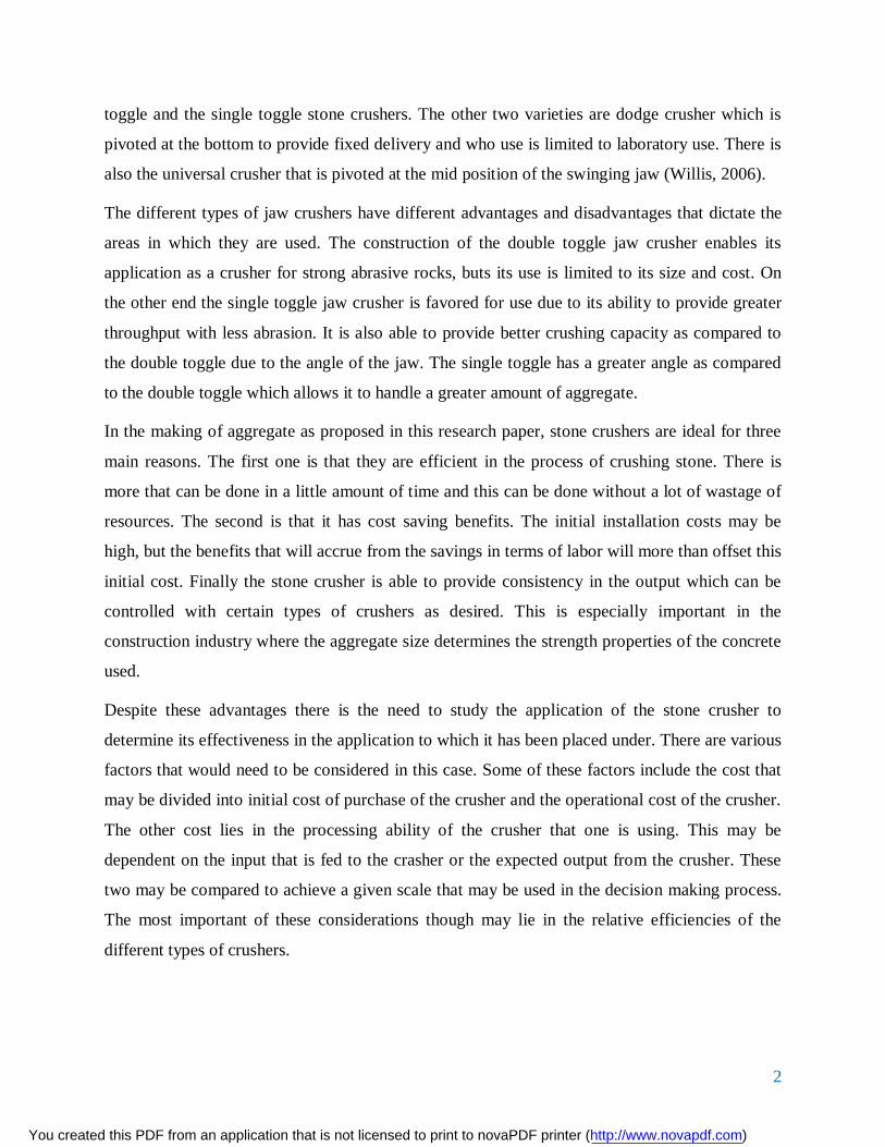
Attrition (abrasion) and Chipping
When stresses are not large enough to cause a fracture, attrition occurs at the weakest parts of a
particle. Parent particle size hardly changes but particle shape is affected so that corners are
chipped away. Generally this means that the particles become more cubic in shape. Formation of
progeny particles via attrition is presented in Figure 4. In order to achieve conditions suitable for
attrition, particle must be loaded from multiple points. Typically, such conditions can be
achieved in an inter particle crushing, where generation of particles are compressed against each
other. Such breakage pattern is dominant in fine crushers used in tertiary and quaternary stage,
where reduction ratio is low.
Figure 4: Formation of progeny particles in attrition [King, 2001]
1.1.2 Summary of Breakage Modes
Breakage pattern is controlled by the intensity of applied crushing energy; the higher the
intensity, the more complete rupture of originating particle is. This dependency between applied
energy and degree of size reduction can be seen clearly from Figure 2, presenting the uni-
axial compression tests of single particle.
These tests also reveal that attrition can be achieved with the lower crushing energy than
cleavage, whereas the shatter requires clearly most crushing energy of all. For every crusher type
You created this PDF from an application that is not licensed to print to novaPDF printer (http://www.novapdf.com)

7
there is a primary breakage mode that is the dominant over the other two. Thus every crusher
type has its own characteristic output curve.
Figure 5: Effect of applied c rushing energy on degree of size reduction during uni-axial compression. Applied
compression ratios were: (from right to left) 0.05, 0.17, 0.25 and crushing energies: 0.007, 0.010, 0.488 kWh/t.
1.2 Problem Statement
In the efficiency one is looking at the input and comparing this to the output that the crusher is
giving in terms of the work that is input into the crusher. In the research paper the examination
will look into the work that is supplied to the driving mechanisms from the motor and how this is
transmitted through the different mechanisms to yield the desired output. The efficiencies of the
different crushers may then be used to make an argument as to which crusher is mechanically
better than the others. This examination will go towards developing the major considerations that
will go into the final decision making in terms of the best crusher. This is despite the fact that
this may not be the only factor that is taken into consideration when considering the type of
crusher to use.
You created this PDF from an application that is not licensed to print to novaPDF printer (http://www.novapdf.com)

8
1.3 Aim of the Project
The aim of the project was to carry out a force analysis of a crank rocker single toggle
mechanism and compare it with the Pittman type stone crusher. Furthermore, make
recommendations on the conclusion drawn from the two mechanisms and make determinations
as to the best mechanism for use in stone crushing.
1.4 Methodology
o The project will begin by looking at past literature that is available on the existing
crusher mechanisms.
o Visiting various large scale stone crushing facilities in the country to determine their
needs.
o Studying the laboratory stone crusher to understand its operational mechanisms and
output.
o Analyze data from theoretical single toggle force analysis and comparing this with
laboratory experiment data.
You created this PDF from an application that is not licensed to print to novaPDF printer (http://www.novapdf.com)

9
CHAPTER 2
2.1 Literature Review
In considering the literature that is available on the jaw crusher there are two basic approaches
that one may take. The first would be to consider the theoretical background that has been
developed on the different types of jaw crushers. This considers texts on mechanics that look at
crushers and different academic journals that have researched the development of the available
information on the jaw crusher. The second approach would be to look at the information that is
presented for industrial crushers.
Hartman in his text indicate that the first jaw crusher was patented in 1830 and that there have
been many different types since then. This includes the single toggle, dodge type and the Blake
type also known as the double toggle. The double toggle finds use where the more heavy duty
crushing is being applied (Hartman et al. 1992). They introduce the first major difference
between the different type of crushers as well as some of the terminologies used.
Hendricks has built on this by examining the working mechanisms of the different types of jaw
crushers. This examination provides an introductory and basic look at the working mechanism of
the jaw crushers without examining the technical aspects (Hendricks, 2000). Additional
information on this is provided by Swain, who also goes ahead to consider some preliminary
scientific deduction on the workings of the jaw crusher. This is by providing mathematical
calculations by which the capacity of the jaw crusher may be determined (Swain, Patra & Roy,
2011).
Others such as Cao et al. presented data that has been used in the kinematic study of single
toggle jaw crushers (Cao et al. 2006). This includes by authors such as Deepak who presented
mathematical developed kinematic equations using this data. This data was also used by Garnaik
in the development of graphs using a mathematical program called MATLAB (Garnaik, 2010).
You created this PDF from an application that is not licensed to print to novaPDF printer (http://www.novapdf.com)

10
CHAPTER 3
3.1 Functional Analysis
3.1.1 Jaw crusher Working Principle
The jaw crusher is composed of a main frame, eccentric shaft, flywheel, toggle plate, jaw plate,
tension rod, fixed jaw, and movable jaw and so on. The motor or internal combustion engine
transmits power through a belt drive, drives the moving jaw, through the eccentric shaft, to
execute periodic motion towards, and away from the fixed jaw. The angle between the toggle
plate and the moving jaw plate varies as the moving jaw moves through its cycle. The feed
material will be crushed in this process. The final crushed material will be discharged from the
outlet, at the bottom of the crusher. The moving jaw of the crusher enables periodic crushing and
discharging to realize batch production.
Figure 6: Cutaway view of a jaw crusher
You created this PDF from an application that is not licensed to print to novaPDF printer (http://www.novapdf.com)

11
3.1.2 Jaw Crusher Components
1. Frame: Is a heavy duty design steel plates welded construction. It is welded by 2co shield
arc process. Stress is relieved after fabrication.
2. Crashing Chamber: Deep crushing chamber with sharp nip angle ensures high crushing
capacity.
3. Swing Jaw and Main Bearing Housing: Swing jaw is a robust steel casting with fully
machined face to support swing jaw. Main bearing housing allows removal from frame as
an integral sub assembly and permits of change over unit in the event bearings damage.
4. Flywheel: Balances the inertia forces and promotes smooth operation of the crusher.
5. Eccentric Shaft: Is a forged from hardened and tempered chrome molybdenum steel.
They have large diameters to suit heavy duty application
6. Bearing: Fag or SKF heavy duty self-aligning double row bearings on swing jaw and
main frame Bath oil lubrication ensures positive lubrication. Bearing life under typical
quarry application is in excess of 8 years.
7. Hydraulic Cylinder: The cylinder allows easy adjustment of discharge setting by moving
toggle block to the desired setting.
8. Shim: Allows easy adjustment of closed side setting.
9. Toggle plate: Designed to shear protecting crusher components if none crushable objects
is induced to crushers
10. Check plates: Plates are made of manganese steel castings that allow easy replacement.
11. Jaw plate: High manganese steel castings can be reversed allowing extended life. Wedge
or lug system allows easy replacement.
The single toggle jaw crusher is versatile and it can be used to crush rocks, whose hardness may
range from medium-hard to extremely hard, as well as different kinds of ore, building rubble and
glass, among other hard materials. It is widely used in a variety of demolition, extraction,
reclamation and recycling industries, but especially, in the mining and construction sectors
(AUBEMA Jaw Crushers, 2013; SBM Mining and Construction Machinery, 2013).
You created this PDF from an application that is not licensed to print to novaPDF printer (http://www.novapdf.com)
12
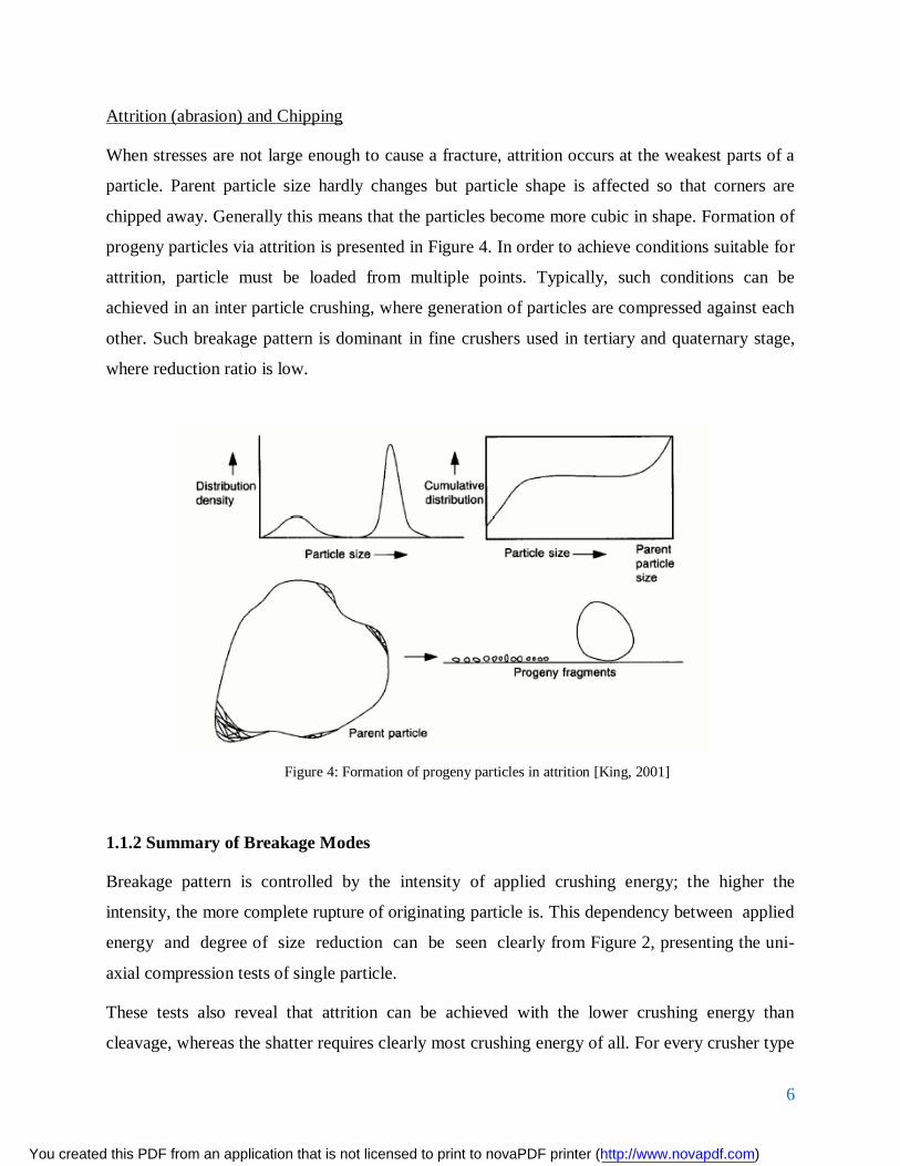
The heart of the crushing mechanism of a jaw crusher consists of two metallic jaw plates that are
slightly and oppositely inclined away from the vertical to form a V Shaped crushing zone with a
wide upper opening and a narrow lower opening. One of the jaw plates are fixed while the other
is movable and referred to as the swing jaw. When in operation, the charge of material to be
crushed is fed into the crushing zone through the upper opening. The swing jaw is driven to
execute a cyclic reversing
Motion and to apply cyclic intermittent compressive forces that crush the charge of material
against the fixed jaw. As the larger lumps of material are crushed into smaller lumps, they fall,
under gravity, into the narrower lower sections of the crushing zone, where they are crushed
again into even smaller lumps. This process is repeated until the charge of material is all crushed
into aggregates that are small enough to fall out of the crusher, through the opening at the lower
end of the crushing zone (Gupta and Yan, 2006). The crushing mechanism is enclosed in a box-
like steel frame. The jaw crusher can be crawler track-mounted or trailer-mounted to realize a
mobile unit that can be repositioned, when the need arises, even as the work advances.
Moreover, in many cases, the jaw crusher can be easily disassembled for relocation or access to
confined places (Carter, 1999). This enables the jaw crusher to be used in both surface and
underground mining. Other advantages of the jaw crusher include its simplicity in structure and
mechanism, reliability, ease of maintenance, and high capacity, as compared to other types of
crusher such as the Cone crusher, the gyratory crusher and the various designs of impact crushers
(Zhong and Chen, 2010).
Today, the most commonly used types of jaw crusher are the single toggle and the double toggle
designs. The original double toggle jaw crusher was designed by Eli Whitney Blake in the USA
in 1857 (Mular et. al., 2002). The motion of the swing jaw in a double toggle crusher is such that
it applies an almost purely compressive force upon the material being crushed. This minimizes
wear on the crushing surfaces of the jaws and makes the double toggle jaw crusher suitable for
crushing highly abrasive and very hard materials. Even today, the Blake design, with some
comparatively minor improvements, can still be found in mines and quarries around the world.
The single toggle design, which was developed between the 1920s and the 1950s, is a simpler,
lighter crusher (Mular et. al., 2002). Its swing jaw has an elliptical rolling motion such that it
applies a compressive as well as a rubbing force on the material being crushed. This has a force-
You created this PDF from an application that is not licensed to print to novaPDF printer (http://www.novapdf.com)

13
feeding effect that improves the throughput of the device but it also tends to cause rapid wear of
the crushing surfaces of the jaws.
However, the single toggle jaw crusher has a lower installed cost, as compared to the double
toggle design. Improvements in materials and design have made the single toggle jaw crusher
more common today as the primary crusher in quarrying operations (The Institute of Quarrying
Australia, 2013). According to Carter (1999), sales of the single toggle jaw crusher exceed those
of the double toggle jaw crusher by a factor of at least nine to one. The crushing action of a jaw
crusher is brought about by the motion of its swing jaw and the forces that it exerts on the
material being crushed (Gupta and Yan, 2006; Pennsylvania Crusher Corporation, 2006).
Therefore, in the study and design of the jaw crusher, it is important to understand the kinematics
of the swing jaw.
This paper sets out to obtain a complete kinematical description of the single toggle jaw crusher,
from first principles. The Pittman jaw crusher on the other hand, are Jaw crushers most easily
recognized any qurrying operation. They are also probably the oldest design of mechanical
crushers, except for spalling hammers and stamping batteries.
They generally consist of a heavy-duty steel box-like frame, fitted with a vertical, or nearly
vertical, fixed crushing jaw, at one end, and a moving swing jaw, at the opposite end. The swing
jaw is provided with a mechanism that drives it and causes it to move with a cyclic oscillating
motion. Thus, the swing jaw continuously moves towards and away from the fixed jaw, and in
so doing it subjects the charge of material to be crushed to continuous waves of compression.this
movement can beprovided a motor or internal combustion enginefixed as part of the crusher.the
motor or internal combustion enginetransmits powerthrough a belt drive,driving the movable
jaw,through the eccentric shaft,to excecutethe periodic motion towards and away fromthe fixed
jaw.
You created this PDF from an application that is not licensed to print to novaPDF printer (http://www.novapdf.com)
14
CHAPTER 4
4.1 Kinematic Analysis of the Jaw Crusher
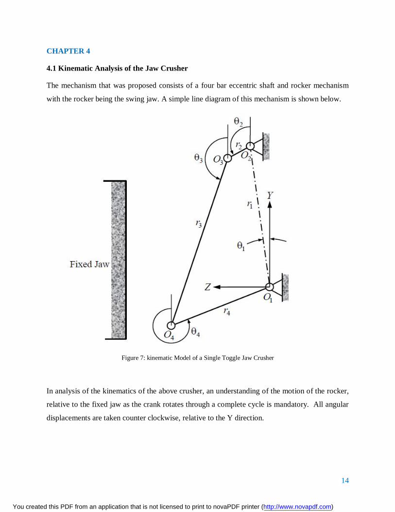
The mechanism that was proposed consists of a four bar eccentric shaft and rocker mechanism
with the rocker being the swing jaw. A simple line diagram of this mechanism is shown below.
Figure 7: kinematic Model of a Single Toggle Jaw Crusher
In analysis of the kinematics of the above crusher, an understanding of the motion of the rocker,
relative to the fixed jaw as the crank rotates through a complete cycle is mandatory. All angular
displacements are taken counter clockwise, relative to the Y direction.
You created this PDF from an application that is not licensed to print to novaPDF printer (http://www.novapdf.com)

15
4.1.1 Position and Displacement Analysis
The analysis of the position and displacement can be accomplished through use of the well-
known vector loop closure method, which is illustrated in figure 8 below.
Figure 8: Vector- Loop Closure
In Fig. 8, the vector loop equation can be written as follows:
04321 rrrr (1)
Equation 1 above can be re-written in complex notation as follows:
You created this PDF from an application that is not licensed to print to novaPDF printer (http://www.novapdf.com)

16
43214321
jjjj erererer (2)
Noting the Euler Identities:
sincossincos
jeje
j
j
(3)
For conciseness the following notation can also be introduced:
ii
ii
sc
sincos
(4)
Using equations (3) and (4), equation (2) can be re-written as:
0444333222111 jscrjscrjscrjscr (5)
The real and imaginary parts of the equation (5) could be separated to obtain:
)()(
44332211
44332211
srsrsrsrcrcrcrcr
(6)
Furthermore, both equations above could be squared to yield the following equations:
2
42
443432
32
32
22
221212
12
1
24
244343
23
23
22
222121
21
21
22
22
srssrrsrsrssrrsr
crccrrcrcrccrrcr (7)
By adding the corresponding terms in equation (7) above and noting that 122 ii sc , we obtain
the following:
24343434
23
22212121
21 2)(2 rssccrrrrssccrrr (8)
Rearranging equation (6) we have:
)()(
44221133
44221133
srsrsrsrcrcrcrcr
(9)
From trigonometry:
kikiki cossinsincoscos (10)
By substituting equation (9) into (8) and using the identity in equation (10), we obtain:
You created this PDF from an application that is not licensed to print to novaPDF printer (http://www.novapdf.com)

17
2442
24
23
22
2114411221
cos2cos2cos2
rrrrrrrrrr
(11)
From figure (11) above, 1 is a fixed quantity and for given values of 1r , 2r , 3r and 4r the value of
1 will be known.
Also, motion of the crank 32OO is the input motion. It may be considered to be a rotation at
uniform angular velocity 2 . At an instant time t, after commencement of motion, the value 2 in
radians will be determined as follows:
tt 22 )( (12)
For given lengths of the four links in the mechanism, equation (11) can be used to determine the
values of 4 that correspond to any given value of 2 .
Equation (11) describes all possible spatial configurations of the mechanism, for given lengths of
the four links. For the case where 01 , equation (11) becomes:
24422
42
32
22
1441221 cos2cos2cos2 rrrrrrrrrr (13)
Dividing each term by 422 rr , we obtain the following equation:
2442
24
23
22
21
42
12
4
1 cos2
coscos
rr
rrrrrr
rr
(14)
The above equation can also be written as follows:
42
24
23
22
21
3
2
12
4
11
2434221
2
coscoscos
rrrrrrK
rrK
rrK
KKK
(15)
You created this PDF from an application that is not licensed to print to novaPDF printer (http://www.novapdf.com)

18
Equation (15) is called the Freudenstein equation. For given values of the lengths of the four
links, the equation can be used to determine values of 4 that correspond to any given values
of 2 .
The data in Table 1 shall be used to demonstrate how the kinematic equations are applied.
Table 1: Dimensions of a PE 400x600 Single Toggle Jaw Crusher
11 sin r (mm) 11 cos r (mm) 2r (mm) 3r (mm) 4r (mm)
45.3 815.7 12 1085 455
From the data in Table 1 above, it follows to good approximation that,
mmr 8171 and 18.31 . This data will be used for the analysis of the crusher.
4.1.2 Angular displacement of the Swing Jaw
Equation (6) can be re-arranged to obtain the following equation:
44332211
44332211
srsrsrsrcrcrcrcr
(16)
Equation (16) can be substituted into equation (8) and using equation (10), the following is
obtained:
`1313
24
23
22
2123321221
cos2cos2cos2
rrrrrrrrrr
(17)
For given lengths of the four links in the mechanism, along with the value of 1 , equation (17)
can be used to determine corresponding values of 3 for the given values of 2 . When compared
to equation (11), equation (17) is of greater utility in describing the motion of the swing jaw,
relative to that of the crank.
If 01 equation (17) reduces to the following:
`23322
12
22
32
4313221 cos2cos2cos2 rrrrrrrrrr (18)
You created this PDF from an application that is not licensed to print to novaPDF printer (http://www.novapdf.com)

19
Equation (18) can be divided through by 322 rr to obtain the following:
2332
21
22
23
24
32
12
3
1 cos2
coscos
rr
rrrrrr
rr
(19)
The equation (19) above could be rewritten as follows:
32
21
22
23
24
3
2
12
3
11
2333221
2
coscoscos
rrrrrrK
rrK
rrK
KKK
(20)
Equation (20) may be regarded as another version of Freudenstein’s equation. For the given
values of the lengths of the four links, the equation can be used to determine the values of 3 that
correspond to given values of 2
By using the data in table 1, equation (17) could be reduced as follows:
223
22
21
33231
sin042.0cos75.09.628.3sin
68cos0sincos
KKKKKK
(21)
In equation (21), for any given value of 2 , 1K 2K and 3K can be determined.
Moreover, the first of equations (21) may be re-written as follows:
)sin(cos 33231 KKK (22)
By squaring both sides of equation (37), using the well-known trigonometric
identity 22 sin1cos and then re-arranging the result, the following can be obtained:
You created this PDF from an application that is not licensed to print to novaPDF printer (http://www.novapdf.com)

20
21
23
32
22
21
332
2
0sinsin
KKC
KKBKKA
CBA
(23)
For any given value of 2 , the equation (23) above is quadratic in 3sin and can therefore be
solved to yield 2 values of 3 . Thus there are two possible configurations of the four bar
mechanism in figure 8 for any possible value of 2 .
However, it is important to note that only one configuration is proper, that is, the one giving
value of 3 lying between 090 and 0180 as shown in figure 9 below.
The angle 3 being greater than 0180 would be absurd as per the crusher design and is therefore
unsuitable.
Figure 9: Another possible configuration of the Mechanism
You created this PDF from an application that is not licensed to print to novaPDF printer (http://www.novapdf.com)

21
Table 2: Analytically determined values of 3 for a given values of
2
2 (Degrees) 3 (Degrees) 2 (Degrees) 3 (Degrees)
0 160.2 195 160.8
15 160.5 210 160.6
30 160.7 225 160.4
45 160.9 240 160.1
60 161.1 255 160.1
75 161.3 270 160
90 161.5 285 159.7
105 161.5 300 159.7
120 161.6 315 159.8
135 161.5 330 159.9
150 161.4 345 160
165 161.3 360 160.2
180 161.1
For one full cycle of the crank, the minimum value of 3 is 07.159 , whereas the maximum value
of 3 is 06.161 . Thus, the range of variation of the inclination of the rocker, swing jaw, to the
vertical is about 09.1 . With the length of the rocker being mm1085 , this range of angular
oscillation of the swing jaw translates to a throw of about 24 mm at the lower end of the swing
jaw. A graph of the variation of 3 with 2 is shown in figure 10 below:
You created this PDF from an application that is not licensed to print to novaPDF printer (http://www.novapdf.com)

22
Figure 10: Variation of Rocker Angle with Crank Angle
By using equation (23) and the values of constants 1K , 2K and 3K , the following is obtained:
84.3955
46.8564245.4635
084.3955sin46.8564sin45.4635
21
23
32
22
21
332
KKC
KKBKKA
(24)
Equation (24) can be solved using the quadratic formula to yield two values of 3 which are
64.166 and 34.166
During the cycle of motion of the mechanism, two particular phases are of interest. These special
phases, which are known as toggle positions occur when the crank 32OO and the coupler 43OO
fall on the same straight line. For this to happen, either 3 must be equal to )180( 2 or 3 must
be equal to 2 . When these conditions are used in equation (17), along with the data in Table 1, it
is found that the toggle positions will occur when 35.1612 and when 3402 . In determining
You created this PDF from an application that is not licensed to print to novaPDF printer (http://www.novapdf.com)

23
the toggle positions, due regard must be given to the fact that, for each value of 2 , there will be
two possible configurations of the mechanism, only one of which will be suitable for the proper
operation of the crusher.
4.1.3 Position and Displacement of a Point in the Swing Jaw
It should be informative to be able to determine the motion of a point in the swing jaw,
particularly on the crushing surface of the swing jaw, as it varies with the motion of the crank.
The position of such a point would be fixed relative to that of the swing jaw 43OO (Fig. 7). For
the purpose of locating such a point, the coordinate system illustrated in Fig. 11 will be used.
You created this PDF from an application that is not licensed to print to novaPDF printer (http://www.novapdf.com)

24
Figure 11: Location of a Point P in the Swing Jaw
In Fig. 11, the ''ZY coordinate reference frame has its origin at 3O and it is fixed in the swing
jaw. The point P too is fixed in the swing jaw and its position is located by the vector r 5 , of
magnitude 5r , whose origin is at 3O and whose direction is indicated by the angle 5 . Thus:
You created this PDF from an application that is not licensed to print to novaPDF printer (http://www.novapdf.com)

25
55
55
sin'cos'
rzry (25)
The direction of the vector r 5 taken relative to the Y direction is indicated by the angle 5 , such
that:
90535 (26)
Thus the following equation is obtained:
5353535
5353535
sincoscossinsincoscoscossinsincossin (27)
In the special case where 905 , 5 becomes equal to 3 and the point P then lies on the
line 4OO , at a distance of 5r from 3O .
In Fig. 15, the location of point P relative to the YZ coordinate reference frame may now be
expressed as follows:
552211
552211
sinsinsincoscoscos
rrrzrrry
P
P (28)
By using equations (27), equations (28) can be re-written as follows:
535352211
535352211
coscossinsinsinsinsincoscossincoscos
rrrzrrry
P
P (29)
In the special case where 905 , equations (29) reduce to the following:
352211
352211
sinsinsincoscoscos
rrrzrrry
P
P (30)
Given the lengths 1r , 2r , 3r and 4r of the links, along with the angle 1 , equations (17) and (30)
can be used to determine the locus of any point on the line 43OO , for a complete cycle of rotation
of the crank 32OO , provided that the distance 5r of that point from 3O is known.
Five points were selected along the length of the line 43OO , whose distances from 3O are given in
Table 3 below. The point 1P is coincident with 3O and the point 5P is coincident with 4O . The
rest of the points are uniformly spaced along the length of the line 43OO .
You created this PDF from an application that is not licensed to print to novaPDF printer (http://www.novapdf.com)

26
Table 3: Locations of Selected Points along the Coupler
Point 1P 2P 3P 4P 5P
5r (mm) 0 271.25 542.5 813.75 1085
Using equations (30), along with the data given in Tables 1 and 3, the positions of the points 1P
through to 5P were determined for one complete cycle of motion of the mechanism. The data in
Tables 4 and 5 are representative of the results.
Table 4: Ranges of Displacements in the Y Direction
Point 1P 2P 3P 4P 5P
maxy (mm) 803.75 547.09 290.32 33.46 -223.47
miny (mm) 827.75 572.54 317.45 62.46 -192.44
Range of y 24 25.45 27.13 29 31.03
As can be seen in Table 4, the range of displacement in the Y direction increases monotonously,
and at a slightly increasing rate, as we move from point 1P through to 5P . Motion of the swing
jaw in the Y direction causes a rubbing action between the material being crushed and the swing
jaw, thereby causing the crushing surface of the swing jaw to wear. One could therefore expect
an increasing wear rate as we move from 1P through to 5P . On the other hand, during the
crushing stroke, any motion of the swing jaw in the downward vertical direction forcefully feeds
the material being crushed into the crushing chamber, which is desirable because it increases the
throughput of the crusher.
You created this PDF from an application that is not licensed to print to novaPDF printer (http://www.novapdf.com)

27
Table 5: Ranges of Displacements in the Z Direction
Point 1P 2P 3P 4P 5P
minz (mm) 33.18 126.57 219.02 308.98 396.52
maxz (mm) 57.18 143.67 231.02 320.44 412.44
Range of z 24 17.10 12.00 11.46 15.92
In Table 5, the range of displacement in the Z direction decreases at a decreasing rate, as we
move from point 1P through to 4P but then increases as we move from point 4P to 5P .
Displacement of the swing jaw in the Z direction should be the greater contributor to the crushing
action.
The loci of points 1P through to 5P , for one complete cycle of motion, are shown in Figs. 12 to
16. These loci have been referred to as coupler curves.
You created this PDF from an application that is not licensed to print to novaPDF printer (http://www.novapdf.com)

28
Figure 12: The Locus of Point P1 for One Complete Cycle of Motion
In Figs. 12 to 16, the scales on the Y and the Z axes should be equal in order for the forms of the
loci to be correct. In Fig. 12, the locus of point 1P is the circle that is described by the crankpin
3O and centered at 2O . With the data that were used to determine these loci, this circle has a
radius of mm12 .As can be seen in Figs. 13, 14 and 15, the loci of points 2P , 3P and 4P appear to
be ellipses of varying proportions. As we move from point 2P to 3P and on to 4P , the major axis
of the ellipses grows longer while the minor axis grows shorter. Moreover, the major and minor
axes of these ellipses are increasingly angled relative to the YZ coordinate reference frame.
You created this PDF from an application that is not licensed to print to novaPDF printer (http://www.novapdf.com)

29
Figure 13: The Locus of Point P2 for One Complete Cycle of Motion
You created this PDF from an application that is not licensed to print to novaPDF printer (http://www.novapdf.com)

30
Figure 14: The Locus of Point P3 for One Complete Cycle of Motion
You created this PDF from an application that is not licensed to print to novaPDF printer (http://www.novapdf.com)
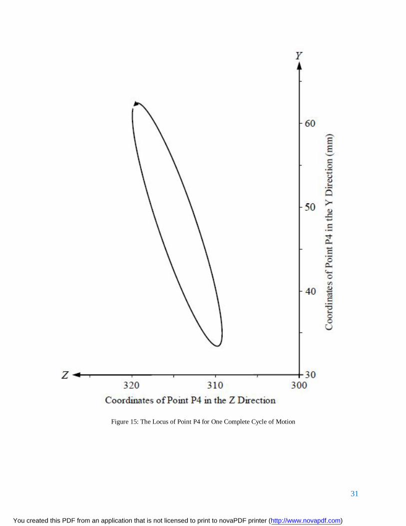
31
Figure 15: The Locus of Point P4 for One Complete Cycle of Motion
You created this PDF from an application that is not licensed to print to novaPDF printer (http://www.novapdf.com)

32
Figure 16: The Locus of Point P5 for One Complete Cycle of Motion
4.1.4 Angular Velocity of the Swing Jaw
An expression for the angular velocity of the coupler (swing jaw) can be obtained by
differentiating equation (17) with respect to time. In doing so, it should be noted that 1r , 1 2r 3r
and 4r are all constants with respect to time. The result of the differentiation is then as follows:
dtdrr
dtd
rrdt
drr
dtdrr
22332
32332
31313
21221
sin
sinsinsin
(31)
Equation (31) can be divided through by 32 rr to obtain the following:
You created this PDF from an application that is not licensed to print to novaPDF printer (http://www.novapdf.com)

33
dtd
dtd
dtd
rr
dtd
rr
323
323
212
3
1313
2
1
sin
sinsinsin
(32)
Moreover, the following additional notation can be introduced:
33
22
dtddt
d
(33)
While 3 is expected to vary with time, the crank (eccentric shaft) is assumed to rotate at
constant rotational velocity and therefore 2 should be constant. According to manufacturer’s
specifications, for a PE 400× 600 single toggle jaw crusher, 2 may be taken to be rpm275
or 18.28 rads . Thus, with the data given in Table 4, equation (32) may be re-written as follows:
13132
13
232
12123
11
32
122
32
123
sin08.68sin
sin
sin753.0sin
8.28
rrK
KrrK
KKKK
KKKK
(34)
In equation (34), for any given value of 2 , with the corresponding value of 4 having been
determined, 1K 2K and 3K will be constants. Equations (34) were used to determine the values
of 3 , as 2 varied from 00 to 0360 . Some of these calculated values are given in Table 6 as
shown below.
You created this PDF from an application that is not licensed to print to novaPDF printer (http://www.novapdf.com)

34
Table 6: Analytically Determined Values of 3 for Given Values of 2
2 (degrees) 3 (rad/s) 2 (degrees)
3 (rad/s)
0 0.407 195 -0.463
15 0.443 210 -0.476
30 0.450 225 -0.454
45 0.429 240 -0.397
60 0.381 255 -0.373
75 0.309 270 -0.206
90 0.216 285 -0.087
105 0.108 300 -0.036
120 -0.009 315 -0.154
135 -0.129 330 -0.259
150 -0.242 345 -0.345
165 -0.341 360 -0.407
180 -0.417
For one full cycle of rotation of the crank, the minimum value of 3 was found to be 1476.0 rads or rpm55.4 while the maximum value of 3 was found to be 1451.0 rads or rpm3.4 .
Thus, the angular velocity of the coupler (swing jaw) is generally small.
A graph of the variation of 3 with 2 is shown in Fig. 21 below:
You created this PDF from an application that is not licensed to print to novaPDF printer (http://www.novapdf.com)

35
Figure 17: Variation of Swing Jaw Velocity 3 with Crank Angle 2
A graph of the variation of 3 with 2 is shown in Fig. 16. Note in Fig. 16 that the angular
velocity of the swing jaw becomes zero at the instances where the angular displacement of the
swing jaw attained maximum and minimum values, as can be seen in Fig. 16. This is to be
expected since it is at these instances that the rate of change of angular displacement of the swing
jaw instantaneously becomes zero.
4.1.5 Velocity of a Point in the Swing Jaw
The position of a point in the swing jaw is determined by equations (29). In the particular case
where the point falls on line 43OO , its position is then described by equations (30). Thus the
vertical and horizontal components of the velocity of a point on line 43OO can be determined by
differentiating equations (30) with respect to time, to obtain the following:
353222
353222
coscossinsin
rrzrry
PPH
PPV
(35)
You created this PDF from an application that is not licensed to print to novaPDF printer (http://www.novapdf.com)

36
With the data given in Table 1 and with the value of 2 taken to be 28.8 radians per second,
equations (30) can be re-written as follows:
3532
3532
coscos3456.0sinsin3456.0
rzry
PPH
PPV
(36)
In equations (36), if 5r is given in meters, then, for any given value of 2 , the corresponding
values of 3 and 3 can be determined, as was earlier done, and therefore the velocity
components PV and PH can be determined in meters per second.
For the values of 5r given in Table 6, the values of the velocity components PV and PH were
determined for one complete cycle of motion of the mechanism. The data in Tables 7 and 8 are
representative of the results.
Table 7: Velocities in the Y Direction
Point 1P 2P 3P 4P 5P
miny (m/s) -0.346 -0.366 -0.389 -0.414 -0.442
maxy (m/s) 0.346 0.367 0.393 0.421 0.452
In Table 7, negative values of velocity indicate a vertically downward motion while positive
values indicate a vertically upward motion. As can be seen in Table 7, the maximum value of the
component of velocity in the Y direction, whether it is directed upward or downward, increases
monotonously, and at a slightly increasing rate, as we move from point 1P through to 5P . Once
again, this could suggest an increasing rate of wear as we move from 1P through to 5P .
Moreover, as we move from point 2P through to 5P , slightly greater velocities are achieved in
the vertically upward direction, as compared to the vertically downward direction, though the
difference is small.
The vertical components of velocity for points 1P through to 5P are compared graphically in
Fig. 18, for one complete rotation of the crank. It can be seen in Fig. 17 that the angular
You created this PDF from an application that is not licensed to print to novaPDF printer (http://www.novapdf.com)

37
oscillation of the swing jaw instantaneously stops when 81.1182 and when 625.2952 .
With no angular oscillation of the swing jaw, its motion becomes a pure translation and all the
points in it have the same vertical components of velocity, as can be seen in Fig. 18.
Figure 18: Vertical Components of Velocity of Points in the Swing Jaw
You created this PDF from an application that is not licensed to print to novaPDF printer (http://www.novapdf.com)

38
Table 8: Velocities in the Z Direction
Point 1P 2P 3P 4P 5P
minz (m/s) -0.346 -0.383 -0.421 -0.46 -0.50
maxz (m/s) 0.346 0.383 0.421 0.46 0.50
In Table 8, negative values of velocity indicate that the swing jaw is moving away from the fixed
jaw while positive values indicate that the swing jaw is moving towards the fixed jaw. It can be
seen in Table 8, the maximum value of the component of velocity in the Z direction increases at
an almost constant rate, as we move from point 1P through to 5P . Moreover, as we move from
point 1P through to 5P , the maximum value of the component of velocity in the Z direction
appears to remain unchanged, whether the swing jaw is moving towards the fixed jaw or away
from the fixed jaw.
The horizontal components of velocity for points 1P through to 5P are compared graphically in
Fig. 19, for one complete rotation of the crank. Again, the instances when the angular oscillation
of the swing jaw instantaneously stops are evidenced in Fig. 19 by the crank positions at which
all the points in the swing jaw have equal horizontal (as well as vertical) components of velocity.
You created this PDF from an application that is not licensed to print to novaPDF printer (http://www.novapdf.com)

39
Figure 19: Horizontal Components of Velocity of Points in the Swing Jaw
In Figs. 18 and 19, it can be seen that, for approximately the first quarter of rotation of the crank,
the swing jaw moves vertically downward and horizontally towards the fixed jaw, thus forcefully
feeding the charge of material into the crushing chamber and simultaneously crushing it. For the
second quarter of rotation of the crank, the swing jaw still moves vertically downward but
horizontally away from the fixed jaw, thus letting the crushed material fall through the crushing
chamber. For the third quarter of rotation of the crank, the swing jaw moves vertically upwards
and horizontally away from the fixed jaw, still letting the crushed material fall through the
crushing chamber.
Finally, in the last quarter of rotation of the crank, the swing jaw continues to move vertically
upwards but horizontally towards the fixed jaw, thus beginning another crushing cycle.
You created this PDF from an application that is not licensed to print to novaPDF printer (http://www.novapdf.com)
40
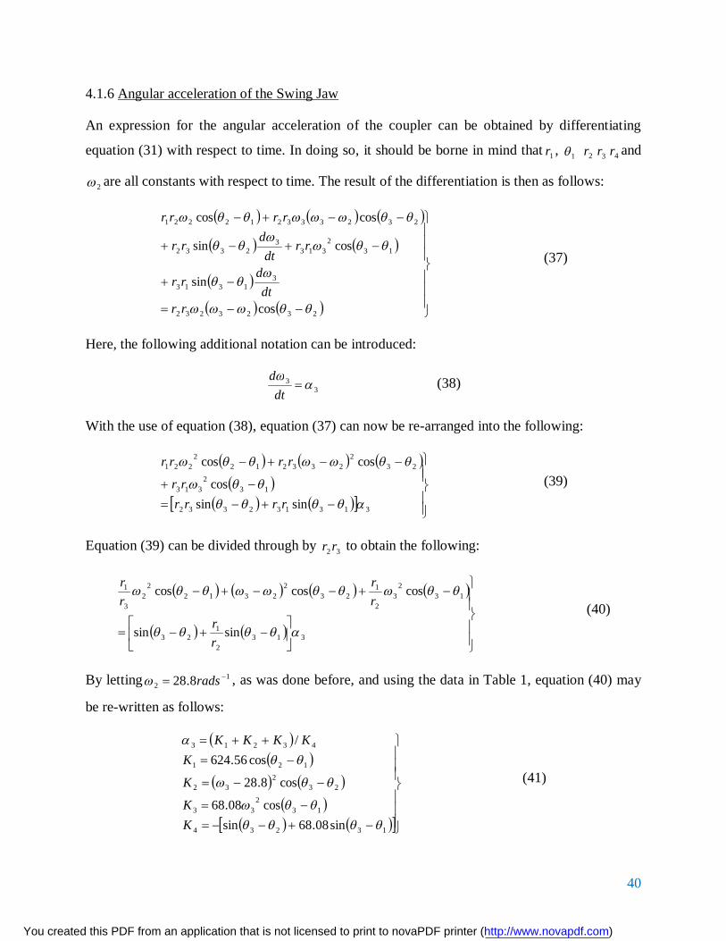
4.1.6 Angular acceleration of the Swing Jaw
An expression for the angular acceleration of the coupler can be obtained by differentiating
equation (31) with respect to time. In doing so, it should be borne in mind that 1r , 1 2r 3r 4r and
2 are all constants with respect to time. The result of the differentiation is then as follows:
2323232
31313
132
3133
2332
232333212221
cos
sin
cossin
coscos
rrdt
drr
rrdt
drr
rrrr
(37)
Here, the following additional notation can be introduced:
33
dtd (38)
With the use of equation (38), equation (37) can now be re-arranged into the following:
313132332
132
313
232
2332122
221
sinsincos
coscos
rrrrrr
rrrr (39)
Equation (39) can be divided through by 32 rr to obtain the following:
3132
123
132
32
123
22312
22
3
1
sinsin
coscoscos
rr
rr
rr
(40)
By letting 12 8.28 rads , as was done before, and using the data in Table 1, equation (40) may
be re-written as follows:
13234
132
33
232
32
121
43213
sin08.68sincos08.68
cos8.28
cos56.624/
KK
K
KKKKK
(41)
You created this PDF from an application that is not licensed to print to novaPDF printer (http://www.novapdf.com)

41
With the values of 3 and 3 that correspond to given values of 2 having been determined;
equations (41) were used to determine the values of 3 as 2 was varied from 0 to 360 . Some
of the calculated values are given in Table 9.
For one complete cycle of motion of the swing jaw, the minimum value of its angular
acceleration occurred at 9.1232 and was found to be −13.208 radians per square second
while the maximum value of its angular acceleration occurred at 2.2912 and was found to be
13.573 radians per square second. Thus, the angular acceleration of the swing jaw can attain
substantial magnitudes.
You created this PDF from an application that is not licensed to print to novaPDF printer (http://www.novapdf.com)

42
Table 9: Analytically Determined Values of 3 for Given Values of 2
2 (degrees) 3 (rad/s2) 2 (degrees) 3 (rad/s2)
0 5.415 195 -3.315
15 2.362 210 0.543
30 -0.767 225 4.384
45 -3.820 240 7.858
60 -6.657 255 10.659
75 -9.175 270 12.573
90 -11.150 285 13.490
105 -12.538 300 13.406
120 -13.179 315 12.407
135 -12.960 330 10.617
150 -11.813 345 8.226
165 -9.741 360 5.415
180 -6.841
A graph of the variation of 3 with 2 is shown in Fig. 20 below:
You created this PDF from an application that is not licensed to print to novaPDF printer (http://www.novapdf.com)

43
Figure 20: Angular Accelerations of the Coupler versus Crank Angle
4.1.7 Acceleration of a Point in the Swing Jaw
The vertical and horizontal components of the acceleration of a point on line 43OO can be
determined by differentiating equations (35) with respect to time, to obtain the following:
353352
3222
2
353352
3222
2
sinsinsin
sincoscos
rrrza
rrrya
PPH
PPV
(42)
In equations (42), if 5r is given, then, for any given value of 2 , the corresponding values of 3 ,
3 and 3 can be determined, and therefore the acceleration components PVa and PHa can also
be determined.
For the values of 5r given in Table 6, the values of the acceleration components PVa and
PHa were determined, using equations (42), for one complete cycle of motion of the mechanism.
The data in Tables 10 and 11 are representative of the results.
You created this PDF from an application that is not licensed to print to novaPDF printer (http://www.novapdf.com)

44
Table 10: Accelerations in the Y Direction
Point 1P
2P
3P
4P
5P
miny (m/s2) -9.953 -10.467 -11.092 -11.817 -12.629
maxy (m/s2) 9.953 10.467 11.420 12.252 13.132
In Table 10, negative values indicate an acceleration that is directed vertically downward and
would either slow down the vertical component of velocity of the swing jaw, if it were moving in
the upward direction, or speed up the vertical component of velocity of the swing jaw, if it were
moving in the downward direction. Positive values indicate an acceleration that is directed
vertically upward and would either slow down the vertical component of velocity of the swing
jaw, if it were moving in the downward direction, or speed up the vertical component of velocity
of the swing jaw, if it were moving in the upward direction. It can be seen in Table 10, the
maximum value of the component of acceleration in the Y direction increases monotonously.
This is at a slightly increasing rate, as we move from point 1P through to 5P .
Table 11: Accelerations in the Z Direction
Point 1P
2P
3P
4P
5P
minz (m/s2) -9.953 -8.993 -8.064 -7.176 -6.339
maxz (m/s2) 9.953 8.807 7.716 6.720 5.887
In Table 11, negative values indicate an acceleration that is directed horizontally away from the
fixed jaw and would either slow down the horizontal component of velocity of the swing jaw, if
it were moving towards the fixed jaw, or speed up the horizontal component of velocity of the
swing jaw, if it were moving away from the fixed jaw. Positive values indicate an acceleration
that is directed horizontally towards the fixed jaw and would either slow down the horizontal
You created this PDF from an application that is not licensed to print to novaPDF printer (http://www.novapdf.com)

45
component of velocity of the swing jaw, if it were moving away from the fixed jaw, or speed up
the horizontal component of velocity of the swing jaw, if it were moving towards the fixed jaw.
As can be seen in Table 11, the maximum value of the component of acceleration in the Z
direction decreases monotonously and at a slightly decreasing rate, as we move from point
1P through to 5P .
The vertical components of acceleration for points 1P through to 5P are compared graphically
in Fig. 25, for one complete rotation of the crank as shown below.
Figure 21: Vertical Components of Acceleration of Points in the Swing Jaw
It can be seen in Fig. 21 that the angular velocity of the swing jaw instantaneously becomes zero
when 32.262 and when 92.2072 . At these instances, the acceleration of the swing jaw
becomes purely translational and all the points in it have the same vertical component of
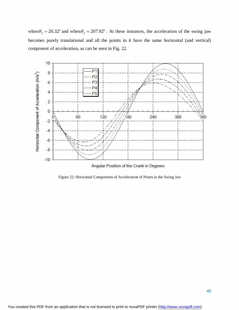
acceleration, as can be seen in Fig. 21.The horizontal components of acceleration for points 1P
through to 5P are compared graphically in Fig. 22, for one complete rotation of the crank. Again
it can be seen in Fig. 21 that the angular velocity of the swing jaw instantaneously becomes zero
You created this PDF from an application that is not licensed to print to novaPDF printer (http://www.novapdf.com)
46
when 32.262 and when 92.2072 . At these instances, the acceleration of the swing jaw
becomes purely translational and all the points in it have the same horizontal (and vertical)
component of acceleration, as can be seen in Fig. 22.
Figure 22: Horizontal Components of Acceleration of Points in the Swing Jaw
You created this PDF from an application that is not licensed to print to novaPDF printer (http://www.novapdf.com)

47
4.2 Static Force Analysis of the Crusher Mechanism
The forces acting in the links of the proposed mechanism are illustrated in Fig. 23 below:
Figure 23: Direction of the Forces and Torques acting on the links
In performing the static force analysis it shall be assumed that the masses of the links, as well as
friction forces are negligible. 2T is the driving torque, applied at the crank axis 2O to drive the
crank and the entire crusher mechanism. 3T is the torque, acting about the swing jaw axis 3O ,
due 2F and 3F are the forces in links and 3 ,respectively and they are all assumed to be
compressive. Considering the motion of the crank, the free body diagram in Fig. 24 below is
obtained:
You created this PDF from an application that is not licensed to print to novaPDF printer (http://www.novapdf.com)

48
Figure 24: Free body diagram of the Crank
The equilibrium of moments on the crank, about the joint 2O , leads to the following equation:
22322322
222322232
cossincossin0
rFFTTrFrF
ZY
ZY
(43)
Considering the motion of the rocker link, the following free body diagram could be drawn:
FY32
FZ32
T2
F2
O3
O2
You created this PDF from an application that is not licensed to print to novaPDF printer (http://www.novapdf.com)

49
Figure 25: Free body diagram of the Rocker link
The equilibrium of moments on the rocker, about the joint 4O , yields the following equation:
3334333433
333433343
cossincossin0
rrFrFTTrFrF
ZY
ZY
(44)
If the equilibrium of forces at joint 4O is considered in the Z direction, the following equation is
obtained:
FY23 FZ23
F3
T3
T3
FY43
FZ43
O3
O4
You created this PDF from an application that is not licensed to print to novaPDF printer (http://www.novapdf.com)

50
323343
3343
03343
sin0sin090cos
ZZ
Z
Z
FFFFF
FF
(45)
From equation (45) it follows that:
333423 sinFFF ZZ (46)
Similarly, considering the force acting on the Y direction at joint 4O , the following equation is
obtained:
323343
3343
03343
cos0cos090sin
YY
Y
Y
FFFFF
FF
(47)
Equations (46) and (47) can be substituted into equation (43) to obtain the following equation:
32322
2323322
22332332
sincossinsincos
cossinsincos
FrTFrT
rFFT (48)
Similarly, equations (45), (46) and (47) are substituted into equation 44 to yield the following
result:
3333
33333333
33333333
2sincossinsincos
cossinsincos
FrTFFrT
rFFT (49)
A relationship between 2T and 3T can be obtained by dividing equation (49) by equation (48), to
obtain the following equation:
32
3
32
23
sin2sin
rTrT
(50)
You created this PDF from an application that is not licensed to print to novaPDF printer (http://www.novapdf.com)

51
4.1.1 Determination of 3T Experimentally
The torque applied on the swing jaw 3T was obtained experimentally by using a modified single
toggle small scale stone crusher whose mechanism is shown by the picture below:
Figure 26: Mechanism of a Modified small scale Single Toggle Stone Crusher
Assumptions made during the Experimental Analysis
From Figure 26 above, it is seen that the rocker is not supported directly by the crank like in the
single toggle stone crusher. It has another link that connects the crank to the swing jaw. This
difference led to some assumptions being made for proper analysis.
The assumption that was made when conducting the experiment was that equation (50) can be
used to obtain the torque ratios in both mechanisms. Furthermore, the data used in Table 1 are
dimensions of a large scale stone crusher therefore; another assumption made was that the
dimensions of a large scale stone crusher could be used in conjunction with the power consumed
and angular velocity of a small scale stone crusher to obtain the torque 3T .
You created this PDF from an application that is not licensed to print to novaPDF printer (http://www.novapdf.com)

52
4.2.2 Determination of Power Consumed
The values of voltage and current used to operate the stone crusher were read off from a clamp
meter as 235rms and 8.07rms respectively.
VIP (51)
Where:
P = Power consumed in kilowatts
V = Voltage measured in volts
I = Current measured in amperes
Substituting the values of voltage and current in equation (51) the power consumed is was
determined as follows:
1000
207.82235 P = 3.7929Kw
4.4.3 Determination of Torque applied on the Swing Jaw
The torque applied on the rocker can be determined by using the following equation:
PT (52)
Where:
Angular speed of the motor in rad/s
T = Applied torque in Nm
But: 337rpm (obtained experimentally by use of a tachometer)
Using the information given above and equation (52) the applied torque 3T is obtained as follows:
602337
10007929.33
T 107.4763Nm
You created this PDF from an application that is not licensed to print to novaPDF printer (http://www.novapdf.com)

53
Equation (50) was then used in conjunction with the data in Table 1 to obtain the torque
2T applied at different crank angles. Moreover, the normalized torque ratios 23 /TT at different
crank angles 2 were obtained. The following table is representative of the results obtained.
Table 12: Values of 2T and 23 /TT at different Crank Angles
θ2 θ3 T3/T2 T2 θ2 θ3 T3/T2 T2
0 160.235 0
15 160.4574 196.5741 6.240344 195 160.8539 -51.3573 -23.8854
30 160.6913 -33.982 -36.0982 210 160.6075 745.6186 1.645198
45 160.9217 -81.7182 -15.0112 225 160.3634 -71.122 -17.2477
60 161.1343 55.84326 21.96666 240 160.1398 -60.8192 -20.1695
75 161.3157 100.7792 12.17206 255 159.9529 304.1136 4.033658
90 161.4541 -573.255 -2.13987 270 159.816 -56.9966 -21.5222
105 161.54 88.96087 13.7891 285 159.7383 90.48816 13.55636
120 161.5668 -92.5863 -13.2492 300 159.7241 4.601326 266.5949
135 161.5314 -16.939 -72.4179 315 159.773 -234.912 -5.22191
150 161.435 223.0355 5.499976 330 159.8805 -114.954 -10.6711
165 161.2828 27.93072 43.91902 345 160.0383 -120.048 -10.2183
180 161.0845 88.87776 13.80199 360 160.235 51.51498 23.8123
You created this PDF from an application that is not licensed to print to novaPDF printer (http://www.novapdf.com)

54
Figure 27: Variation of Normalized torque ratio with Crank angle obtained experimentally
A graph was drawn for a complete crank rotation. It was observed that the first spike in Fig. 26
indicates the great amplification of the crushing force that occurs at the toggle position, which
corresponds to a crank angle of about 90 . Theoretically, the crushing force amplification should
be infinite at this toggle position. The second spike in Fig. 26 occurs at a crank angle of
about 210 . This spike corresponds to the second toggle position of the mechanism. However,
as the crank rotates from 90 to 210 , the crusher would be on the idle stroke with the swing jaw
being retracted and no work being done in crushing the feed material. Therefore, the second
spike has no physical meaning in so far as crushing of the feed material is concerned.
You created this PDF from an application that is not licensed to print to novaPDF printer (http://www.novapdf.com)

55
CHAPTER 5
5.1 Discussion
The main objective of the experiment was to compare the characteristics of a horizontal Pittman
toggle stone crusher with the single toggle stone crusher. This comparison was used in
determining which of these methods was better. The analysis major consideration was the force
transmission characteristics of the two crushers.
In this project, we set out to analyze the force transmission characteristics of a single toggle
stone crusher. This began with the theoretical analysis of the force transmission characteristics of
the single toggle stone crusher. This was achieved by deriving the equations of the forces along
each member of the free body diagram in figure 23.
The swing jaw positional displacement was determined using the following equation,
352211
352211
sinsinsincoscoscos
rrrzrrry
P
P
Graphs were drawn for different values of 3 and selected points, 1P to 5P . In table 5, the range
of displacement in the Z direction increases, as we move from point 1P through to 5P .
Displacement of the swing jaw in the Z direction is the greater contributor to the crushing
action. The loci of points 2P through to 5P , for one complete cycle of motion, are shown in
Figs. 13 to 16. As can be seen in Figs. 13, 14 and 15, the loci of points 2P , 3P and 4P are
straight lines of varying lengths. As we move from point 1P to 5P , the lines increase in length
in both axes.
The following equation (32) was used to determine the velocity, 3 , as 2 varied from 0 to
360 .
dtdrr
dtd
rrdt
drr
dtdrr
22332
32332
31313
21221
sin
sinsinsin
You created this PDF from an application that is not licensed to print to novaPDF printer (http://www.novapdf.com)

56
For one full cycle of rotation of the crank, the minimum value of 3 was found to
be srad /42.0 , while the maximum value of 3 was found to be srad /415.0 . Thus, the angular
velocity of the coupler (swing jaw) is generally small.
The velocity of a point on the swing jaw was calculated using the following equation (36):
3532
3532
coscos3456.0sinsin3456.0
rzry
PPH
PPV
Data was tabulated and a graph of the velocity variation on the different points 1P to 5P was
shown in Figs. 18 and 19.
It was seen that, for approximately the first quarter of rotation of the crank, the swing jaw moves
vertically downward and horizontally towards the fixed jaw, thus forcefully feeding the charge of
material into the crushing chamber and simultaneously crushing it. For the second quarter of
rotation of the crank, the swing jaw still moves vertically downward but horizontally away from
the fixed jaw, thus letting the crushed material fall through the crushing chamber. For the third
quarter of rotation of the crank, the swing jaw moves vertically upwards and horizontally away
from the fixed jaw, still letting the crushed material fall through the crushing chamber. Finally,
in the last quarter of rotation of the crank, the swing jaw continues to move vertically upwards
but horizontally towards the fixed jaw, thus beginning another crushing cycle.
The angular acceleration was analyzed using the following equation, (40);
3132
123
132
32
123
22312
22
3
1
sinsin
coscoscos
rr
rr
rr
For one complete cycle of motion of the swing jaw, the minimum value of its angular
acceleration occurred at 1252 and was found to be 213 rads radians per second while the
maximum value of its angular acceleration occurred at 2902 and was found to be 25.13 rads .
Thus, the angular acceleration of the swing jaw can attain substantial magnitudes.
The normalized torque was analyzed by the following equation, (50);
You created this PDF from an application that is not licensed to print to novaPDF printer (http://www.novapdf.com)

57
32
3
32
23
sin2sin
rTrT
The graphs obtained from theoretical and experimental data have the same profile with one spike
formation in the positive torque ratio range and another in the negative torque ratio range. This
shows that there is significant change in direction of the torque applied. The greatest crushing
action is experienced at the two angles where the spike occurs. This is at 90 and 210 .
However there was a difference in the profile of the graph obtained from the theoretical analysis
and that of the experimental data. It is evident that the graph obtained theoretically was
asymptotic to the x-axis at 1. The experimental graph appeared slightly sinusoidal to the x axis.
This is credited to the assumptions made in the theoretical analysis did not take into account all
the variables in the practical analysis. One assumption is that the load distribution on the swing
jaw is a point load with the torque acting at the center of the arm. The load distribution in the
experiment could not be accurately determined. This is why five arbitrary points were taken from
the swing jaw to study the displacement, velocity and acceleration of various points of the swing
jaw.
You created this PDF from an application that is not licensed to print to novaPDF printer (http://www.novapdf.com)

58
5.1.1 Comparison between the Single Toggle and the Horizontal Pittman Stone Crushers
From the discussion, it is evident that the single toggle stone crusher has an oscillatory motion of
the swing jaw as opposed to the impact crushing of backward and forward in the horizontal
Pittman stone crusher. The oscillatory motion in the single toggle jaw crusher introduces a
rubbing effect between the swing jaw and the material being crushed thus the teeth of the swing
jaw wear out faster as compared to the horizontal Pittman stone crusher.
The magnitudes of the acceleration of the swing jaw in the single toggle jaw crusher are slightly
higher as compared to the acceleration magnitudes in the horizontal Pittman stone crusher.
Furthermore, these magnitudes are attained faster by the crank in the single toggle jaw crusher.
This implies that the crushing speed of the single toggle jaw crusher is better than the horizontal
Pittman crusher in cases where crushing time is considered a factor. However, the single toggle
jaw crusher has the disadvantage of overheating the joints in its mechanism quicker as compared
to the horizontal Pittman jaw crusher. This is because the high velocity that the rocker and crank
move at, causing friction between the joints.
Furthermore this increases the cost of maintenance of the single toggle jaw crusher as compared
to the horizontal Pittman jaw crusher. The single toggle jaw crusher also has increased
maintenance costs due to the rotational movements of the swing jaw meaning it has to be
replaced more frequently. Despite this, the Single toggle jaw crusher is less expensive in terms of
the initial purchase cost.
If the time taken to begin work is considered, it is evident that the single toggle jaw crusher takes
less time to start crushing the fed material as compared to the horizontal Pittman jaw crusher.
This is because in the horizontal Pittman stone crusher, the second spike occurs at around 252
as shown in the figure below:
You created this PDF from an application that is not licensed to print to novaPDF printer (http://www.novapdf.com)

59
-650
-500
-350
-200
-50
100
250
400
0 30 60 90 120 150 180 210 240 270 300 330 360
Angular Position of the Crank in Degrees
Nor
mal
ized
Tor
que
Rat
io
Figure 28: Theoretical variation of Normalized torque ratio with Crank Angle of the Horizontal Pittman jaw crusher
5.2 Conclusion
The main aim of the project was to compare the characteristics of the horizontal Pittman stone
crusher and the single toggle stone crusher.
This was done by mainly considering the torque transmission characteristics of the two types of
crushers. The graphical representation of these two mechanisms was then done. Experimental
data was used to simulate this torque transmission characteristic for a large scale stone crusher
using previously established dimensions.
5.3 Recommendations
If maintenance in considered a high priority factor, the stone crusher should secure trouble free
operation and increased uptime. For this to be achieved the following factors should be
considered:
Bearings are grease lubricated and should have grease-filled labyrinth seals to prevent
entry of dust.
You created this PDF from an application that is not licensed to print to novaPDF printer (http://www.novapdf.com)

60
Automatic lubrication system that can be connected to existing control systems for
remote alarm indication ensuring protection of roller bearings.
Quick and easy installation of jaw breaks by using clamping and support bars to fix the
jaw plates to the crusher.
The flywheel guards should be made as compact and service friendly as possible. The flywheel
guards should be bolted onto the crusher’s side plates and effectively protects operators from
potentially dangerous moving parts. Viewing windows and access doors allow service crews to
inspect and service the crusher. Their use also gives greater access to the crusher as the guards
are not laying on the service platform.
In conclusion, the feed chute should be custom designed to effectively guide the feed material
into the crusher’s cavity. Jaw and cheek plate removal and installation are carried out without
having to move or remove the feed chute. The feed chute is bolted to the crusher and can be
removed for other maintenance purposes.
5.3.1 Summary of the Advantages of the Recommended Ideas
The recommendations above have the following advantages:
1. Easy automation of the crusher.
2. Full mobility with the lokotrack range.
3. High quality and reliability.
4. Outstanding performance.
5. Low operating and installation costs.
You created this PDF from an application that is not licensed to print to novaPDF printer (http://www.novapdf.com)

61
References 1. Cao, J., X. Rong and S. Yang (2006). Jaw Plate Kinematical Analysis for Single Toggle
Jaw Crusher Design. International Technology and Innovation Conference, 2006, Section
1: Advanced Manufacturing Technology. Pages 62-66.
2. Carmichael, R. D. and E. R. Smith (1962). Mathematical Tables and Formulas. Dover
Publications Incorporated, New York.
3. Carter, Russell A. (1999). New Jaw Crushers are Reliable, Affordable and Transportable.
Rock Products, July 1999. Available at
http://www.rockproducts.com/index.php/features/51-archives/1240.pdf (accessed in May
2013).
4. Deepak, B. B. V. L. (2010). Optimum Design and Analysis of (the) Swinging Jaw Plate of
a Single Toggle Jaw Crusher. A Master of Technology Thesis. Department of
Mechanical Engineering, National Institute of Technology, Rourkela, Odisha, India.
Available at http://www.scribd.com/doc/37399105/Deepak-Project-on-Jaw-Crusher
(accessed in May 2013).
5. Erdman, A. G. and G. N. Sandor (1991). Mechanism Design, Volume 1. Prentice-Hall.
6. Garnaik, Sobhan K. (2010). Computer Aided Design of (the) Jaw Crusher. A Bachelor of
Technology Thesis. Department of Mechanical Engineering, National Institute of
Technology, Rourkela, Odisha, India. Available at
http://ethesis.nitrkl.ac.in/1812/1/thesis_sobhan.pdf (accessed in May 2013).
7. Gupta, A. and D. S. Yan (2006). Mineral Processing, Design and Operations: An
Introduction. Chapter 4: Jaw Crushers. Elsevier. Monday, 19 August 2013 34 of 35
8. Ham, C. W., E. J. Crane and W. L. Rogers (1958). Mechanics of Machinery, Fourth
Edition. McGraw-Hill Book Company Incorporated.
9. Hartman, H. L., Seeley W. Mudd Memorial Fund of AIME., & Society for Mining,
Metallurgy, and Exploration (U.S.). (1992). SME mining engineering handbook.
Littleton, Colo: Society for Mining, Metallurgy, and Exploration.
10. Henan Hongxing Mining Machinery Company Limited (2013). Available at
http://www.hxjqchina.com/UpLoadFile/01.pdf (accessed in January 2013).
You created this PDF from an application that is not licensed to print to novaPDF printer (http://www.novapdf.com)

62
11. Hendriks, C. F. (2000). Sustainable raw materials: Construction and demolition waste.
Cachan: RILEM Publ.
12. Kalnins, L. M. (2009). Coordinate Systems. Department of Earth Sciences, University of
Oxford. Available at http://www.earth.ox.ac.uk/~larak/MMES/CoordinateSystems.pdf
(accessed in July 2013).
13. Kimbrell, J. T. (1991). Kinematics Analysis and Synthesis. McGraw-Hill Incorporated.
14. Martin George, H. (1982). Kinematics and Dynamics of Machines, Second Edition.
McGraw-Hill Incorporated.
15. Mathcentre (2009). Cartesian Components of Vectors. Available at
http://www.mathcentre.ac.uk/resources/uploaded/mc-ty-cartesian1-2009-1.pdf (accessed
in July 2013).
16. MIT (2013). Review B: Coordinate Systems. Massachusetts Institute of Technology,
Department of Physics. Available at
http://web.mit.edu/8.02t/www/materials/modules/ReviewB.pdf (accessed in July 2013).
17. Monkova, K., P. Monka, S. Hloch and J. Valicek (2011). Kinematic Analysis of the
Quick-Return Mechanism in Three Various Approaches. Technical Gazette 18, 2(2011),
pages 295 to 299. Available at hrcak.srce.hr/file/103770. (downloaded in May 2013).
18. Mular, A. L., N. H. Doug and D. J. Barrat (2002). Mineral Processing Plant Design,
Practice and Control: Proceedings, Volume 1, pages 584 to 605. Society for Mining,
Metallurgy and Exploration, Incorporated (SME).
19. Pennsylvania Crusher Corporation (2006). Handbook of Crushing. Available at
http://www.mne.eng.psu.ac.th/pdf/Handbook%20of%20Crushing2003.pdf
20. SBM Mining and Construction Machinery (2013). A brochure available at
http://www.sbmchina.com/pdf/jaw_crusher.pdf (accessed in May 2013).
21. Shigley, J. E. and J. J. Uicker Jr. (1980). Theory of Machines and Mechanisms. McGraw-
Hill Book Company.
22. Swain, A. K., Patra, H., & Roy, G. K. (2011). Mechanical operations. New Delhi: Tata
McGraw Hill.
You created this PDF from an application that is not licensed to print to novaPDF printer (http://www.novapdf.com)