Embed Size (px)
Citation preview

General rights Copyright and moral rights for the publications made accessible in the public portal are retained by the authors and/or other copyright owners and it is a condition of accessing publications that users recognise and abide by the legal requirements associated with these rights.
Users may download and print one copy of any publication from the public portal for the purpose of private study or research.
You may not further distribute the material or use it for any profit-making activity or commercial gain
You may freely distribute the URL identifying the publication in the public portal If you believe that this document breaches copyright please contact us providing details, and we will remove access to the work immediately and investigate your claim.
Downloaded from orbit.dtu.dk on: Aug 22, 2019
Collisions damage assessment of ships and jack-up rigs
Zhang, Shengming; Pedersen, P. Terndrup; Ocakli, Hasan
Published in:Ships and Offshore Structures
Link to article, DOI:10.1080/17445302.2014.1003173
Publication date:2015
Document VersionPeer reviewed version
Link back to DTU Orbit
Citation (APA):Zhang, S., Pedersen, P. T., & Ocakli, H. (2015). Collisions damage assessment of ships and jack-up rigs. Shipsand Offshore Structures, 10(5), 470-478. https://doi.org/10.1080/17445302.2014.1003173
1
COLLISIONS DAMAGE ASSESSMENT OF SHIPS AND JACK-UP RIGS
Shengming Zhang Lloyd’s Register EMEA., Global Technology Centre, Southampton, UK
P Terndrup Pedersen Department of Mechanical Engineering
Technical University of Denmark
Hasan Ocakli Lloyd’s Register Asia
Republic of Korea
ABSTRACT Ship collision with offshore installations is one of the key concerns in design and assess of platforms performance and safety. This
paper presents an analysis on collision energy and structural damage in ship and offshore platform collisions for various collision
scenarios. The platform or rig is treated as either rigid or flexible and its sensitivity on collision energy and structural damage is
studied. An application example where an ice-strengthened supply vessel collides against a Jack-up rig is analyzed and the crushing
resistance of the involved thin-walled structures is evaluated.
1. INTRODUCTION Offshore platforms and drilling rigs are constantly
serviced by supply vessels during its operations. Collisions
between them are unavoidable. The key concern during design
and operating of the structural system is to make sure that they
have sufficient safety in case of collision incidents.
The current design practice is described for example in the
Guidance Notes for Collision Analysis (2014) published by
Lloyd’s Register. Here a procedure is described and a number
of recognized standards and practices for collision analysis are
listed.
The basic impact design philosophy is that the offshore
structure should be able to withstand accidental conditions from
supply ships drifting out of control with a speed of 2 m/s. Such
an impact may require major repair after the incident but not
lead to total collapse even in a storm with a return period of one
year. The size of traditional typical supply vessels is about
5,000 tonnes in displacement in the North Sea (Gjerde et al
1999). The size of supply vessels has increased in recent years.
Vessels servicing the installations on the Norwegian Shelf have
increased significantly up to 7500–10000 ton displacements
(Storheim and Amdahl, 2014). With the increase in vessel size
the collision energy will also increase. Thus the risk of damages
in case of collisions with supply vessels could be significant.
Therefore, such risks should be carefully assessed and reviewed
(Pedersen 2014).
The aim of the present study is to present an analysis on
collision energy and structural damage in ship and offshore
jack-up rig collisions. An accurate assessment of damages to the
offshore rig is complicated by the problem of specifying the
relevant collision conditions such as ship structural
arrangement, impact velocity, impact angle and position. It will
be shown that it is important to take into account the jack-up
flexibility in order to estimate the impact energy more
accurately which is to be absorbed for structural damage.
Application examples of vessels colliding to a jack-up rig are
analysed and the crushing resistance of the thin-walled
structures is evaluated.
2. ANALYSIS METHODS FOR COLLISION ENERGY The analysis methods for collision energy between
ships and offshore platforms were developed by the authors in
references (Zhang 1999 and Pedersen & Zhang 1998). The
assumptions behind this calculation method are the platform
natural period (typically about 8 s) which is larger than the
duration of the initial force contact between the colliding vessel
and the platform, and that the global displacement of the topside
of the jack-up is small until after the initial maximum contact
forces between the colliding bodies is achieved. The procedure
is also based on an assumption of ship translations in the
horizontal plane only. The crushing load-deflection behavior is
approximately linear, and that the structural response of the
platform has a linear structural response.
The colliding system can be approximated as a two-mass
system where one generalized mass represents the supply vessel
and the other represents the platform, as shown in Figure 1.
Thus, the following force-stiffness relations may represent the
platform behavior:
F k kb p 11 12
F k k Mp b p p p
21 22
where F is the collision force between the supply vessel and
the platform, pF is the transmitted force acting on the
generalized topside mass pM of the jack-up, b is the
2
displacement of the collision point on a leg, and p is the
displacement of the topside.
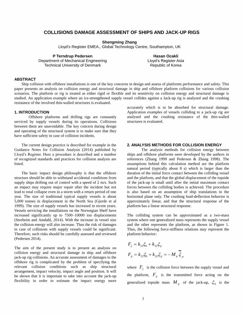
Figure 1. Simplified 2D model of a supply vessel impacting a
chord of a jack-up platform
The interaction between the ship and the jack-up is simplified
as:
Fk for
for
s a b a b
a b
( ),
,
0
0 0
Here k k k k ks11 22 12 21, , , , are stiffness coefficients, and a
is the displacement at the collision point of the supply vessel.
In Pedersen and Jensen (1991), it is shown that at the end of the
collision where the velocities ba
, the displacement (ξp)
of the platform topside can be assumed to be small. Therefore,
we get the generalized force at this moment:
Fk
kFp
21
11
The impact impulse of the collision between the supply vessel
and the platform can be expressed as:
IM
D
a
a
a
[ ( ) ]0
where,
2
2
22
]cos)(sin[
1
1
cos1
1sin
1
1
a
acc
a
ayax
a
R
xxy
j
mmD
and aM is the mass of the supply vessel. The radius of the
ship mass inertia around the centre of gravity is aR , the
coordinate of the centre of gravity of the striking ship is
( , )xa 0 , the coordinate of the impact point is ( , )x yc c , the
added mass coefficient for the surge motion is axm and it is
taken 0.05, the added mass coefficient for the sway motion is
aym and it is taken as 0.5 and the added mass coefficient of
moment for the rotation around the centre of the gravity is aj
and it is taken as 0.25 in this paper.
The impact impulse on the generalized platform mass can be
expressed as:
Ik
kMI ppp
11
21
At the end of the crushing, the velocity of the supply vessel and
the velocity of the platform at the collision point are equal. We
get:
a p
k
k
12
11
The velocity of the topside of the platform is obtained as
pp a
a
k
k
k
k
M D
M
( )0
12
11
11
21
The velocity of the ship at the end of the collision can be
expressed as:
3
))0(()1(
sinsin)0( a
axa
axmD
v
))0(()1(
coscos)0( a
aya
axmD
v
))0(()1(
cos)(sin2 a
aaa
acc
aDjR
xxy
where,
( )( )
00
112 21
11
2
aa
p a
k k
k
M
M D
The energy to be absorbed by the crushing of the supply vessel
and deformation of the jack-up rig is:
)(0 psc EEEE
where,
E M m ma ax ay0
2 2 21
21 1 0
[( ) sin ( )cos ] ( ) is the
initial kinetic energy of the supply vessel,
EM
k
k
k
k
M D
M
p
p
p a
a
1
2
0 2
12
11
11
21
2
( )
( )
is the kinetic energy of the
jack-up topside at the end of the collision,
)
)1(
2
)1(
1()0(
2
1
2
11
2112
2
2
11
2112
2
0
ap
aa
ap
aa
as
DM
M
k
kkD
DM
M
k
kkD
MEE
is the kinetic energy of the supply vessel at the end of the
collision.
The energy to be dissipated by the crushing of the ship structure
and/or the jack-up rig is:
)( 0
11
11ps
s
crush EEEkk
kE
The energy stored in the deformation of the platform is:
)( 0
11
ps
s
splatform EEE
kk
kE
3. DAMAGE ANALYSIS AND EXAMPLES
3.1 COLLISION ENERGY ANALYSIS OF SUPPLY
VESSELS COLLIDING TO A JACK-UP RIG Let us consider an ice-strengthened supply vessel
colliding with the leg of the jack-up rig in different locations of
the ship at a velocity of V = 2 m/s in a direction normal to the
colliding ship side. The length of the supply vessel is 82.5m, the
breadth is 18.8m and the displacement is 5,000t. The jack-up
rig is a self-elevating drilling rig with a topside overall length of
84 m, width overall 90 m and depth 9.4m capable of operation
in water depth up to 100m. The generalized mass of the jack-up
is 19700t which was determined from a calculation of the
lowest natural frequency of the jack-up using a beam model
where the fixity at the spud cans are estimated and the
flexibility at the clamping mechanism is determined from a
FEA. The legs of the rig were modelled as equivalent
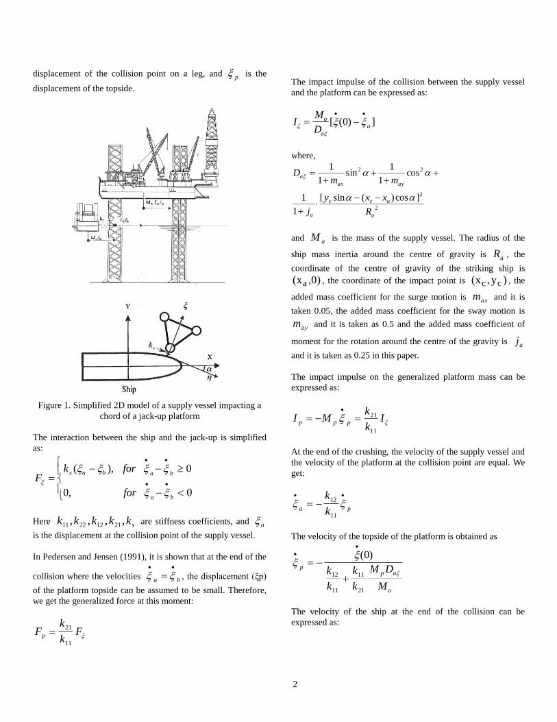
Timoshenko beams. The collision situation is illustrated in
Figure 2. Other collision scenarios can be found in NORSOK
2004.
V
Jack-up
Figure 2. A supply vessel impacting a jack-up rig
Two collision cases were considered to show the effect of the
structural flexibility on the impact energy; the jack-up rig was
considered as rigid as well as flexible. For the flexible case, the
stiffness coefficients in Table 1 are determined from the same
beam model used for estimation of the generalized mass for the
platform. The crushing stiffness ks refers to the results in Figure
7. For different impact locations Figure 3 shows the total kinetic
energy of the supply vessel just before impact, the energy
released for crushing of ship and/or platform in the case of a
rigid platform and in the case of a flexible jack-up structure,
and finally the elastic energy stored in global deformations of
the jack-up.
Table 1: Stiffness coefficients for the flexible case
Coefficients MN/m
11k 34.5
22k 48.9
2112 kk -27.8
sk 48.0

4
It is seen from the results in Figure 3 that the energies released
for crushing are reduced considerably if the flexibility of the
jack-up rig is considered. For the case where the supply vessel
is colliding sideways to the rig with impact midship, the
collision energy to be absorbed by structural crushing is 15MJ
for the rigid case which is equal to the total initial kinetic
energy and it is 5.03MJ for the flexible case. The platform
absorbs 7MJ in elastic bending of the collided leg. The
remaining energy of 2.97MJ is stored in the supply vessel and
the platform in kinetic form. So, it is important to consider the
flexibility of the platform in ship-platform collision analysis.
Figure 3. Energy analysis for the 5,000t supply vessel impacts
the jack-up rig
If the jack-up rig hit by a 10,000t vessel, the energies to be
absorbed by crushing of the vessel and the platform are
calculated and presented in Figure 4. It is seen that for the case
where the supply vessel hits the rig sideway at midship, the ship
and jack-up will absorb 8.39MJ by crushing and the jack-up leg
will store 11.68MJ by elastic bending. The remaining energy of
9.93MJ is stored in the supply vessel and the platform in kinetic
form.
Figure 4. Collision energy to be absorbed by the 10,000t supply
vessel and the platform
For a central head on collision the energy released for crushing
of the bow and jack-up structure is found to be 5.88 MJ for the
5000 t supply vessel and 10.25 MJ for 10 000 t vessel in the
flexible case.
3.2 DAMAGE ANALYSIS METHODOLOGY OF SUPPLY
VESSELS COLLIDING TO A JACK-UP RIG When the colliding ship types and sizes and the
distribution of energy released for crushing are known, the next
step in a consequence analysis is to determine the distribution of
crushing damages to be absorbed by the ships and to the jack-up
structure.
The breakdown of damages between the involved structures
depends on the relative strength of the ship structure and the
impacted parts of the jack-up leg. If the ship is assumed to be
infinitely stiff all the energy has to be dissipated by the jack-up
structure. However, normally it will be much more cost
effective to take into account the finite strength of the colliding
ships. In this case both the striking ship and the installation will
undergo local damage and absorb energy. When this is the
situation the design is based on shared energy. If the strength of
the jack-up is so large that the major part of the energy can be
expected to be absorbed by the striking vessel then the
installation is said to be strength designed. Thus, in order to
determine the consequences of the energy released for structural
damage, it is necessary first to determine the relative strength of
the involved structures.
3.3 LOCAL DAMAGE TO SUPPLY VESSEL The damage caused by the supply vessel can be
estimated by detailed FEA, See for example Paik I and II 2007,
and Samuelides 2014. But often also simplified procedures are
used. The methodologies used in the following to determine the
local capacity/damage of vessels were developed by the authors
in references (Zhang 1999 and Pedersen & Zhang 2000). Figure
5 illustrates the deformation/damage modes of a cylinder
crushing into the side of a supply vessel. The main deformation
mode in the side shell is plastic tension and it is folding and
crushing in deck and bottom. Approximations for the force-
displacement relations for side shell can be expressed as:
))((3
4 10
b
b
b
HtFp
01 bbb
b
Rb 0 , ( Rb 0 )
Approximations for the force-displacement relations for the
deck or for the outer or inner bottom can be expressed as:
5
33.0
33.1
05.0
67.083.1
0
1290.1
1262.1
btbtFd
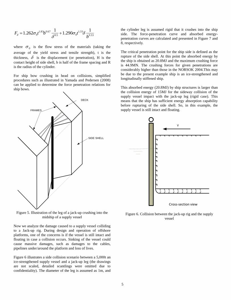
where 0 is the flow stress of the materials (taking the
average of the yield stress and tensile strength), t is the
thickness, is the displacement (or penetration), H is the
contact height of side shell, b is half of the frame spacing and R
is the radius of the cylinder.
For ship bow crushing in head on collisions, simplified
procedures such as illustrated in Yamada and Pedersen (2008)
can be applied to determine the force penetration relations for
ship bows.
SIDE SHELL
DECK
FRAMES
Figure 5. Illustration of the leg of a jack-up crushing into the
midship of a supply vessel
Now we analyze the damage caused to a supply vessel colliding
to a Jack-up rig. During design and operation of offshore
platforms, one of the concerns is if the vessel is still intact and
floating in case a collision occurs. Sinking of the vessel could
cause massive damages, such as damages to the cables,
pipelines under/around the platform and loss of lives.
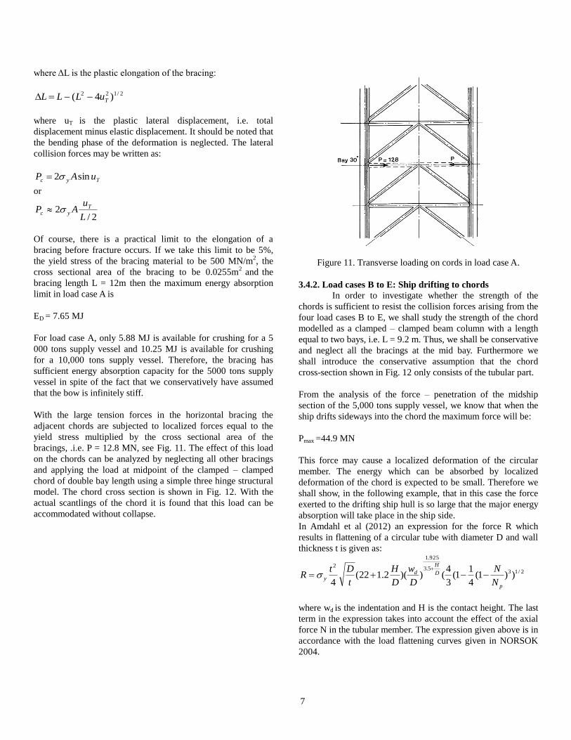
Figure 6 illustrates a side collision scenario between a 5,000t an
ice-strengthened supply vessel and a jack-up leg (the drawings
are not scaled, detailed scantlings were omitted due to
confidentiality). The diameter of the leg is assumed as 1m, and
the cylinder leg is assumed rigid that it crushes into the ship
side. The force-penetration curve and absorbed energy-
penetration curves are calculated and presented in Figure 7 and
8, respectively.
The critical penetration point for the ship side is defined as the
rupture of the side shell. At this point the absorbed energy by
the ship is obtained as 20.8MJ and the maximum crushing force
is 44.9MN. The crushing forces for given penetrations are
considerably higher than those in the NORSOK 2004.This may
be due to the present example ship is an ice-strengthened and
longitudinally stiffened ship.
This absorbed energy (20.8MJ) by ship structures is larger than
the collision energy of 15MJ for the sideway collision of the
supply vessel impact with the jack-up leg (rigid case). This
means that the ship has sufficient energy absorption capability
before rupturing of the side shell. So, in this example, the
supply vessel is still intact and floating.
Cross-section view
V
Figure 6. Collision between the jack-up rig and the supply
vessel

6
Figure 7. Force-penetration curve of the supply vessel crushing
onto the jack-up leg (rigid case)
Figure 8. Energy-penetration curve of the supply vessel
crushing onto the jack-up leg
3.4 LOCAL DAMAGE TO JACK-UP LEGS The methodology used in the following to determine
the local capacity of the jack-up legs against ship impact loads
is a simplified approach based on stepwise determination of
plastic hinges.
Fig. 9 shows a part of the leg of the considered jack-up rig for
collision analysis. For a complete analysis this portion of the leg
has to be analyzed for the five indicated load cases A to E.
Figure 9. Part of jack-up leg with five load cases.
3.4.1 Load case A: Bow collisions.
Let us as a first example consider load case A which is
a bow collision on a horizontal bracing member, see Fig. 10.
Firstly, we assume that the bow of the colliding vessel is
infinitely stiff and the impact is against the mid-part with the
largest contact area and therefore, the largest bow collision
force.
Figure 10. Central load on bracing (Load case A)
If we make the conservative assumption that the secondary
bracing does not exist and that also the diagonal bracings are
ineffective then we can determine the lower bound for the
energy absorbed in the horizontal by membrane yielding simply
as:
LAE yD
7
where ΔL is the plastic elongation of the bracing:
2/122 )4( TuLLL
where uT is the plastic lateral displacement, i.e. total
displacement minus elastic displacement. It should be noted that
the bending phase of the deformation is neglected. The lateral
collision forces may be written as:
Tyc uAP sin2
or
2/2
L
uAP T
yc
Of course, there is a practical limit to the elongation of a
bracing before fracture occurs. If we take this limit to be 5%,
the yield stress of the bracing material to be 500 MN/m2, the
cross sectional area of the bracing to be 0.0255m2
and the
bracing length L = 12m then the maximum energy absorption
limit in load case A is
ED = 7.65 MJ
For load case A, only 5.88 MJ is available for crushing for a 5
000 tons supply vessel and 10.25 MJ is available for crushing
for a 10,000 tons supply vessel. Therefore, the bracing has
sufficient energy absorption capacity for the 5000 tons supply
vessel in spite of the fact that we conservatively have assumed
that the bow is infinitely stiff.
With the large tension forces in the horizontal bracing the
adjacent chords are subjected to localized forces equal to the
yield stress multiplied by the cross sectional area of the
bracings, .i.e. P = 12.8 MN, see Fig. 11. The effect of this load
on the chords can be analyzed by neglecting all other bracings
and applying the load at midpoint of the clamped – clamped
chord of double bay length using a simple three hinge structural
model. The chord cross section is shown in Fig. 12. With the
actual scantlings of the chord it is found that this load can be
accommodated without collapse.
Figure 11. Transverse loading on cords in load case A.
3.4.2. Load cases B to E: Ship drifting to chords
In order to investigate whether the strength of the
chords is sufficient to resist the collision forces arising from the
four load cases B to E, we shall study the strength of the chord
modelled as a clamped – clamped beam column with a length
equal to two bays, i.e. L = 9.2 m. Thus, we shall be conservative
and neglect all the bracings at the mid bay. Furthermore we
shall introduce the conservative assumption that the chord
cross-section shown in Fig. 12 only consists of the tubular part.
From the analysis of the force – penetration of the midship
section of the 5,000 tons supply vessel, we know that when the
ship drifts sideways into the chord the maximum force will be:
Pmax =44.9 MN
This force may cause a localized deformation of the circular
member. The energy which can be absorbed by localized
deformation of the chord is expected to be small. Therefore we
shall show, in the following example, that in this case the force
exerted to the drifting ship hull is so large that the major energy
absorption will take place in the ship side.
In Amdahl et al (2012) an expression for the force R which
results in flattening of a circular tube with diameter D and wall
thickness t is given as:
2/135.3
925.1
2
))1(4
11(
3
4())(2.122(
4 p
D
H
dy
N
N
D
w
D
H
t
DtR
where wd is the indentation and H is the contact height. The last
term in the expression takes into account the effect of the axial
force N in the tubular member. The expression given above is in
accordance with the load flattening curves given in NORSOK
2004.
8
Figure 12. Cross-section of chord.
In the present case the stresses due to axial loads on the chord
are small compared to the yield stress and the buckling stress Np
and it is ignored in the following example.
If the chord depicted in Fig. 12 is approximated by the tubular
part only and the chord material has a yield stress of 700
MN/m2 , a chord diameter of 1 m and an thickness t = 0.053 m
then we obtain the maximum indentation:
Wd1 =0.134 m
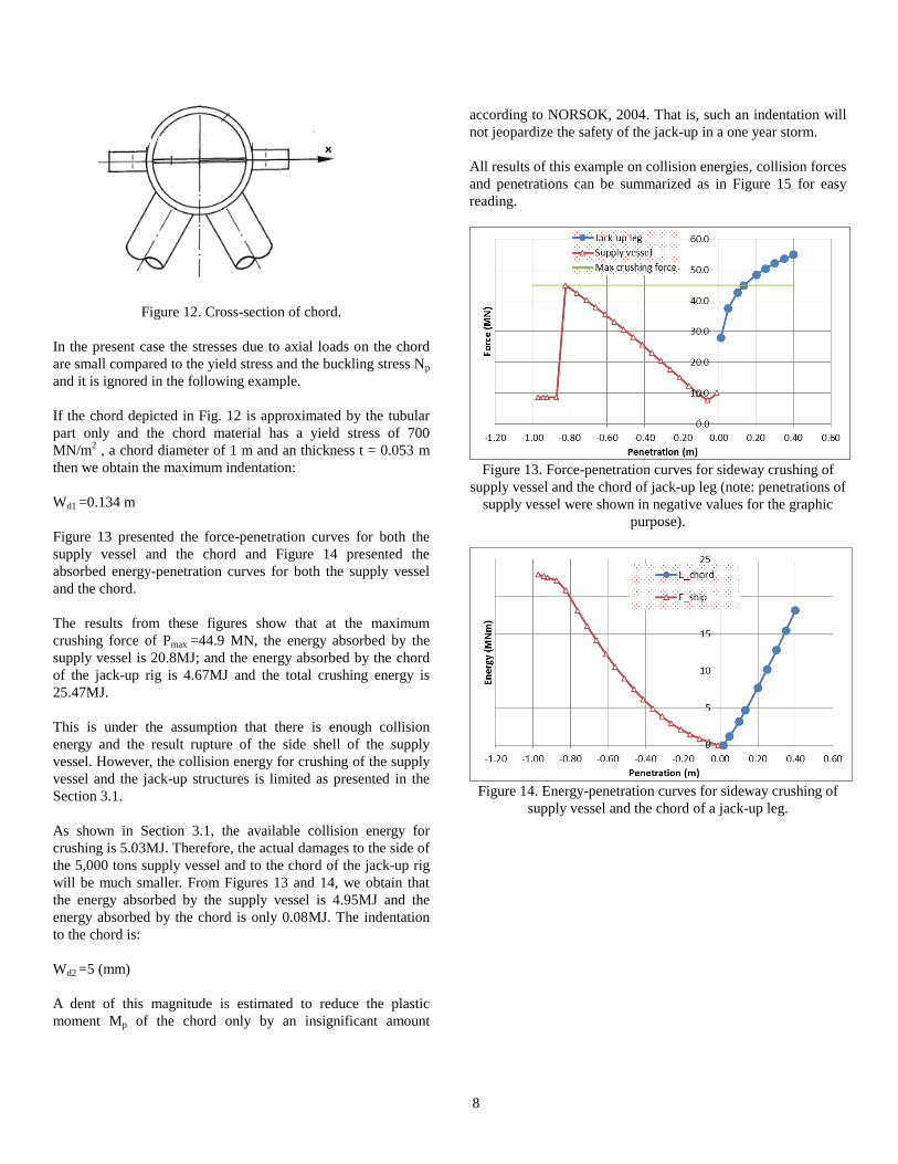
Figure 13 presented the force-penetration curves for both the
supply vessel and the chord and Figure 14 presented the
absorbed energy-penetration curves for both the supply vessel
and the chord.
The results from these figures show that at the maximum
crushing force of Pmax =44.9 MN, the energy absorbed by the
supply vessel is 20.8MJ; and the energy absorbed by the chord
of the jack-up rig is 4.67MJ and the total crushing energy is
25.47MJ.
This is under the assumption that there is enough collision
energy and the result rupture of the side shell of the supply
vessel. However, the collision energy for crushing of the supply
vessel and the jack-up structures is limited as presented in the
Section 3.1.
As shown in Section 3.1, the available collision energy for
crushing is 5.03MJ. Therefore, the actual damages to the side of
the 5,000 tons supply vessel and to the chord of the jack-up rig
will be much smaller. From Figures 13 and 14, we obtain that
the energy absorbed by the supply vessel is 4.95MJ and the
energy absorbed by the chord is only 0.08MJ. The indentation
to the chord is:
Wd2 =5 (mm)
A dent of this magnitude is estimated to reduce the plastic
moment Mp of the chord only by an insignificant amount
according to NORSOK, 2004. That is, such an indentation will
not jeopardize the safety of the jack-up in a one year storm.
All results of this example on collision energies, collision forces
and penetrations can be summarized as in Figure 15 for easy
reading.
Figure 13. Force-penetration curves for sideway crushing of
supply vessel and the chord of jack-up leg (note: penetrations of
supply vessel were shown in negative values for the graphic
purpose).
Figure 14. Energy-penetration curves for sideway crushing of
supply vessel and the chord of a jack-up leg.

9
Figure 15. Force-penetration and energy-penetration curves for
crushing of supply vessel and the chord of a jack-up leg.
3.4.3 Overall jack-up strength and stability.
As a final check of the ability of the rig to sustain the
collision loads, the overall strength of the transversely impacted
leg must be checked as well as the overturning moment must be
ensured to be acceptable. Simplified expressions for the
overturning moment in the worst case of central impacts can be
found in Pedersen and Jensen (1991).
4. CONCLUSION REMARKS The aim of this study has been to illustrate a simplified
procedure for analysis of the ability of jack-up rigs to sustain
operational and accidental impact loads from supply vessels
serving these offshore structures.
An accurate assessment of damages to offshore installations
caused by ship impact loads is complicated by the large amount
of scenarios to be studied. These include various ship sizes and
structures, impact locations, impact velocities and angles, etc.
Therefore, even if comprehensive, time consuming, numerical
analysis procedures exist, see Storheim & Amdahl 2014, then
simplified procedures are needed which are easy to apply and
has sufficient accuracy to ensure the ability of the installation to
resist the impact loads associated with normal operating
conditions and accidental conditions such as supply vessels
drifting out of control against the installation.
The focus of the paper has been on the capability of a large
jack-up rig to sustain the accidental impacts from a
longitudinally stiffened, ice-strengthened 5,000 tons supply
vessel. It is shown that due to the flexibility of the jack-up rig
only part of the initially available kinetic energy is released for
crushing and that the collision energy is accommodated either
by crushing of bracings in the jack-up legs in the case of bow
impacts or by crushing of the side shell in case of sideway
drifting into a leg without total collapse of the jack-up rig.
ACKNOWLEDGMENTS The authors wish to thank Dr Sai Wong and colleagues
at Lloyd’s Register for their comments and support. The views
expressed in this paper are those of the authors and are not
necessarily those of Lloyd’s Register. The main work of the
paper was carried out during the time that the authors worked at
the Technical University of Denmark.
Lloyd’s Register and variants of it are trading names of Lloyd’s
Register Group Limited, its subsidiaries and affiliates. Lloyd’s
Register EMEA (Reg. no. 29592R) is an Industrial and
Provident Society registered in England and Wales. Registered
office: 71 Fenchurch Street, London, EC3M 4BS, UK. A
member of the Lloyd’s Register group.
Lloyd’s Register Group Limited, its affiliates and subsidiaries
and their respective officers, employees or agents are,
individually and collectively, referred to in this clause as the
‘Lloyd’s Register'. Lloyd’s Register assumes no responsibility
and shall not be liable to any person for any loss, damage or
expense caused by reliance on the information or advice in this
document or howsoever provided, unless that person has
signed a contract with the relevant Lloyd’s Register entity for
the provision of this information or advice and in that case any
responsibility or liability is exclusively on the terms and
conditions set out in that contract
REFERENCES Amdahl, J.; Watam, R.; Hu, Z. & Holmås,T., 2012, Broad side
ship collision with jacket legs: Examination of NORSOK
N-004 Analysis Procedure. OMAE Proceedings, Rio de
Janeiro, OMAE2012-84266.
Gjerde, P.; Parsons,S.J. & Igbenabor, S.C. 1999.: Assessment of
jack-up boat impact analysis methodology, Marine
Structures, 12,pp 371-401.
Lloyd’s Register, 2014.: Guidance Notes for Collision Analysis.
Published by Lloyd’s Register Group Limited.
NORSOK Standard N-004, 2004: Design of steel structures,
Appendix A, Design against accidental actions.
Paik, J.K. and Thayamballi, A.K., 2007, Ship-shaped Offshore
Installations: Design, Building, and Operation, Cambridge
University Press, Cambridge, UK.
Paik, J.K., 2007, Practical techniques for finite element
modelling to simulate structural crashworthiness in ship
collisions and grounding (Part I. Theory), Ships and
Offshore Structures, Vol. 2, Issue 1, pp. 69-80.
Paik, J.K., 2007, Practical techniques for finite element
modelling to simulate structural crashworthiness in ship

10
collisions and grounding (Part II Verification), Ships and
Offshore Structures, Vol. 2, Issue 1, pp. 81-85.
Pedersen, P.T., 2014, Risk assessment for ship collisions against
offshore structures, Invited Lecture, Maritime Technology
and Engineering- eds. Guedes Soares& Santos, Taylor &
Francis Group, London, ISBN 978-1-138-02727-5.
Pedersen P. T. and Jensen J. J., 1991, Ship Impact Analysis for
Bottom Supported Offshore Structures, Advances in Marine
Structures II, Elsevier Applied Sciences.
Pedersen P. Terndrup & Zhang S., 1998, On Impact Mechanics
in Ship Collisions, Journal of Marine Structures, Vol. 11,
pp. 429-449.
Pedersen P. Terndrup & Zhang S., 2000, Absorbed Energy in
Ship collisions and Grounding – Revising Minorsky's
Empirical Method", Journal of Ship Research, Vol. 44, No.
2, pp. 140 – 154.
Samuelides, M., 2014, Recent Advances and future trends in
structural crashworthiness of ship structures, Proceedings
of 7th
International Conference on Thin-Walled Structures,
Editors Paik; Kim and Song, ICTWS2014-0007. To be
published in Ships and Offshore Structures?
Storheim M. and Amdahl J., 2014: Design of offshore structures
against accidental ship collisions. Vol. 37, Marine
Structures.
Yamada, Y. and Pedersen, P.T., 2008, A Benchmark Study of
Procedures for Analysis of Axial Crushing of Bulbous
Bows, Marine Structures, Vol. 21. Issues 2-3, pp. 257 –
293.
Zhang S., 1999, The Mechanics of Ship Collisions, PhD theses,
Technical University of Denmark, Denmark, ISBN 87-
89502-05-1.

11