Embed Size (px)
Citation preview
Color Camera
Operating InstructionsBefore operating the unit, please read this manual thoroughly and retain it for future reference.
HDC4800
4-599-592-13 (1)
© 2016 Sony Corporation
2
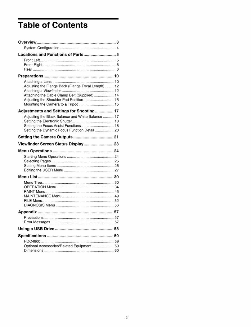
Table of Contents
Overview..................................................................... 3System Configuration.......................................................4
Locations and Functions of Parts............................ 5Front Left ..........................................................................5Front Right .......................................................................6Rear .................................................................................6
Preparations............................................................. 10Attaching a Lens ............................................................10Adjusting the Flange Back (Flange Focal Length) .........12Attaching a Viewfinder ...................................................12Attaching the Cable Clamp Belt (Supplied) ....................14Adjusting the Shoulder Pad Position..............................15Mounting the Camera to a Tripod ..................................15
Adjustments and Settings for Shooting................ 17Adjusting the Black Balance and White Balance ...........17Setting the Electronic Shutter.........................................18Setting the Focus Assist Functions ................................18Setting the Dynamic Focus Function Detail ...................20
Setting the Camera Outputs ................................... 21
Viewfinder Screen Status Display.......................... 23
Menu Operations ..................................................... 24Starting Menu Operations ..............................................24Selecting Pages .............................................................25Setting Menu Items ........................................................26Editing the USER Menu .................................................27
Menu List .................................................................. 30Menu Tree......................................................................30OPERATION Menu ........................................................34PAINT Menu...................................................................45MAINTENANCE Menu ...................................................49FILE Menu......................................................................52DIAGNOSIS Menu .........................................................56
Appendix .................................................................. 57Precautions ....................................................................57Error Messages..............................................................57
Using a USB Drive ................................................... 58
Specifications .......................................................... 59HDC4800 .......................................................................59Optional Accessories/Related Equipment ......................60Dimensions ....................................................................60

Overview
The HDC4800 is a camera unit, equipped with a newly developed S-35mm 4K CMOS imaging sensor, for a Super Motion video camera system. When connected with a BPU4800 Baseband Processor Unit, it supports a maximum of 8× shooting speed in 4K format, and a maximum of 16× in HD format.*Power can be supplied to the camera, and the functions and operability of a system camera, such as an intercom, are supported by connecting the BPU4800 to an HDCU2000/2500 Camera Control Unit.
* HD format is supported by BPU4800 version V1.10 and later.For details, contact a Sony dealer or Sony service representative.
3
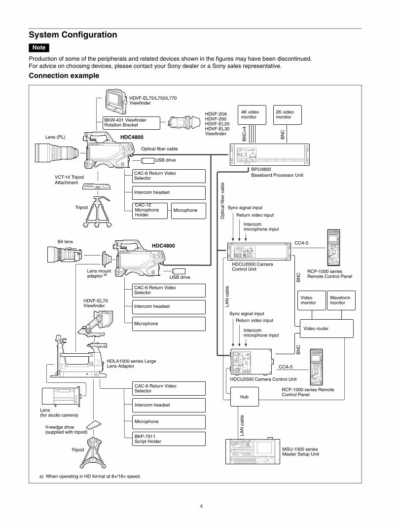
System Configuration
Production of some of the peripherals and related devices shown in the figures may have been discontinued.For advice on choosing devices, please contact your Sony dealer or a Sony sales representative.
Connection example
Note
Lens (PL)
VCT-14 Tripod Attachment
Tripod
USB driveLens mount adaptor a)
HDVF-EL70Viewfinder
CAC-6 Return Video Selector
Intercom headset
Microphone
HDLA1500-series Large Lens Adaptor
Lens(for studio camera)
HDVF-EL75/L750/L770Viewfinder
BKW-401 Viewfinder Rotation Bracket
HDC4800
Optical fiber cable
CAC-6 Return Video Selector
Intercom headset
CAC-12 Microphone Holder
Microphone
HDC4800
HDVF-20AHDVF-200HDVF-EL20HDVF-EL30Viewfinder
a) When operating in HD format at 8×/16× speed.
USB drive
CAC-6 Return Video Selector
Intercom headset
Microphone
BKP-7911Script Holder
V-wedge shoe (supplied with tripod)
Tripod
HDCU2000 Camera Control Unit
BN
C
HDCU2500 Camera Control Unit
MSU-1000 seriesMaster Setup Unit
RCP-1000 series Remote Control Panel
BN
CVideomonitor
Waveformmonitor
Video router
CCA-5LA
N c
able
Opt
ical
fibe
r ca
ble
Hub
RCP-1000 series Remote Control Panel
CCA-5
Sync signal input
Return video input
Intercommicrophone input
BPU4800Baseband Processor Unit
BN
C×
4
2K videomonitor
BN
C
4K videomonitor
LAN
cab
le
Sync signal input
Return video input
Intercommicrophone input
B4 lens
4
Locations and Functions of Parts
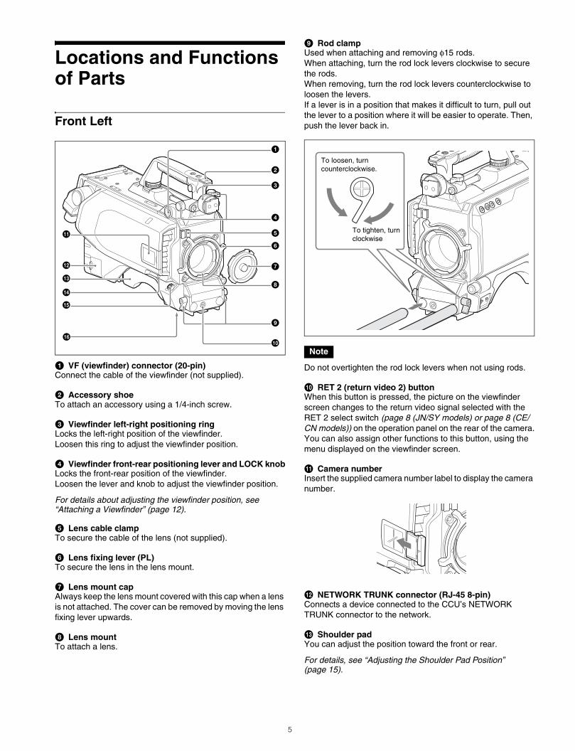
Front Left
a VF (viewfinder) connector (20-pin)Connect the cable of the viewfinder (not supplied).
b Accessory shoeTo attach an accessory using a 1/4-inch screw.
c Viewfinder left-right positioning ringLocks the left-right position of the viewfinder.Loosen this ring to adjust the viewfinder position.
d Viewfinder front-rear positioning lever and LOCK knobLocks the front-rear position of the viewfinder.Loosen the lever and knob to adjust the viewfinder position.
For details about adjusting the viewfinder position, see “Attaching a Viewfinder” (page 12).
e Lens cable clampTo secure the cable of the lens (not supplied).
f Lens fixing lever (PL)To secure the lens in the lens mount.
g Lens mount capAlways keep the lens mount covered with this cap when a lens is not attached. The cover can be removed by moving the lens fixing lever upwards.
h Lens mountTo attach a lens.
i Rod clampUsed when attaching and removing φ15 rods.When attaching, turn the rod lock levers clockwise to secure the rods.When removing, turn the rod lock levers counterclockwise to loosen the levers.If a lever is in a position that makes it difficult to turn, pull out the lever to a position where it will be easier to operate. Then, push the lever back in.
Do not overtighten the rod lock levers when not using rods.
j RET 2 (return video 2) buttonWhen this button is pressed, the picture on the viewfinder screen changes to the return video signal selected with the RET 2 select switch (page 8 (JN/SY models) or page 8 (CE/CN models)) on the operation panel on the rear of the camera.You can also assign other functions to this button, using the menu displayed on the viewfinder screen.
k Camera numberInsert the supplied camera number label to display the camera number.
l NETWORK TRUNK connector (RJ-45 8-pin)Connects a device connected to the CCU’s NETWORK TRUNK connector to the network.
m Shoulder padYou can adjust the position toward the front or rear.
For details, see “Adjusting the Shoulder Pad Position” (page 15).
c
d
e
f
g
h
i
j
a
b
k
l
m
n
o
p
Note
To loosen, turn counterclockwise.
To tighten, turn clockwise
5
n RET 1 (return video 1) buttonThe return video 1 signal from the camera control unit is monitored on the viewfinder screen while this button is pressed. It functions the same as the RET 1 buttons on the handle (page 6) and on the operation panel on the rear of the camera (page 8 (JN/SY models) or page 8 (CE/CN models)).You can also assign other functions to this button, using the menu displayed on the viewfinder screen.
o LENS connector (12-pin)Connect the lens cable. The camera can control the lens functions through this cable.
p Tripod mountAttach the VCT-14 Tripod Attachment when mounting the camera on a tripod.
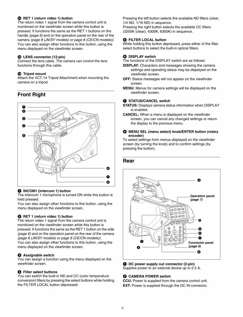
Front Right
a INCOM1 (intercom 1) buttonThe intercom 1 microphone is turned ON while this button is held pressed.You can also assign other functions to this button, using the menu displayed on the viewfinder screen.
b RET 1 (return video 1) buttonThe return video 1 signal from the camera control unit is monitored on the viewfinder screen while this button is pressed. It functions the same as the RET 1 button on the side (page 6) and on the operation panel on the rear of the camera (page 8 (JN/SY models) or page 8 (CE/CN models)).You can also assign other functions to this button, using the menu displayed on the viewfinder screen.
c Assignable switchYou can assign a function using the menu displayed on the viewfinder screen.
d Filter select buttonsYou can switch the built-in ND and CC (color temperature conversion) filters by pressing the select buttons while holding the FILTER LOCAL button depressed.
Pressing the left button selects the available ND filters (clear, 1/4 ND, 1/16 ND) in sequence.Pressing the right button selects the available CC filters (3200K (clear), 4300K, 6300K) in sequence.
e FILTER LOCAL buttonWhile holding this button depressed, press either of the filter select buttons to select the built-in optical filters.
f DISPLAY switchThe functions of the DISPLAY switch are as follows:DISPLAY: Characters and messages showing the camera
settings and operating status may be displayed on the viewfinder screen.
OFF: Status messages will not appear on the viewfinder screen.
MENU: Menus for camera settings will be displayed on the viewfinder screen.
g STATUS/CANCEL switchSTATUS: Displays camera status information when DISPLAY
is enabled.CANCEL: When a menu is displayed on the viewfinder
screen, you can cancel any changed settings or return the display to the previous menu.
h MENU SEL (menu select) knob/ENTER button (rotary encoder)
To select settings from menus displayed on the viewfinder screen (by turning the knob) and to confirm settings (by pressing the button).
Rear
a DC power supply out connector (2-pin)Supplies power to an external device up to 2.5 A.
b CAMERA POWER switchCCU: Power is supplied from the camera control unit.EXT: Power is supplied through the DC IN connector.
b
c
d
e
f
g
h
a
b
c
Operation panel (page 7)
d
a
f
e
g
h
Connector panel (page 9)
6
c Tally lamp and switchON: The tally lamp lights when a tally signal is input to the
connected camera control unit or a call signal is generated in response to pressing the CALL button.
OFF: The tally lamp is prevented from lighting.
d BPU (Baseband Processor Unit) connector (optical/electrical multi-connector)
Connect to BPU4800 Baseband Processor Unit using an optical/electrical multi cable.
e SDI 1 (serial digital interface 1) connector (BNC-type)For 3G-SDI, HD-SDI or HD PROMPTER signal output.
f SDI 2 (serial digital interface 2) connector (BNC-type)For HD-SDI signal output.Functions as an input when used as HD TRUNK IN.
g PROMPTER2 connector (BNC-type)For prompter 2 signal output.Available only when connecting a camera control unit with a prompter 2 input connector.
h CALL buttonWhen this button is pressed, the red tally lamp of the RCP-1000 series Remote Control Panel or the MSU-1000 series Master Setup Unit will light. Use to call the operator of the RCP or MSU.
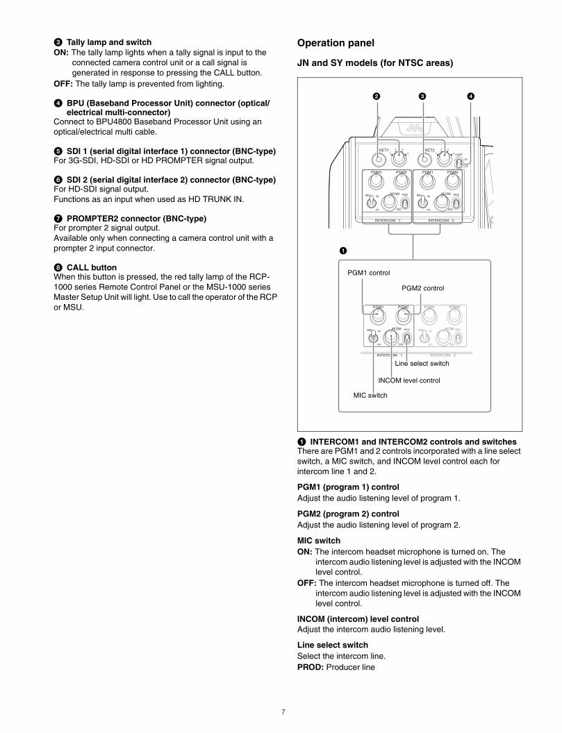
Operation panel
JN and SY models (for NTSC areas)
a INTERCOM1 and INTERCOM2 controls and switchesThere are PGM1 and 2 controls incorporated with a line select switch, a MIC switch, and INCOM level control each for intercom line 1 and 2.
PGM1 (program 1) controlAdjust the audio listening level of program 1.
PGM2 (program 2) controlAdjust the audio listening level of program 2.
MIC switchON: The intercom headset microphone is turned on. The
intercom audio listening level is adjusted with the INCOM level control.
OFF: The intercom headset microphone is turned off. The intercom audio listening level is adjusted with the INCOM level control.
INCOM (intercom) level controlAdjust the intercom audio listening level.
Line select switchSelect the intercom line.PROD: Producer line
b c
a
PGM1 control
PGM2 control
Line select switch
INCOM level control
d
MIC switch
7
ENG: Engineer line
b RET 1 (return video 1) button and select switchPress the button to display the return video signal selected with the switch on the viewfinder screen.
c RET 2 (return video 2) button and select switchIf you use an additional return video system in addition to return video 1, press the button to display the return video signal selected with the switch on the viewfinder screen.
The RET 1 button has priority over the RET 2 button if both buttons are pressed.If RET 1 and RET 2 buttons are pressed at the same time, the two buttons function as the RET 3 button according to the setting of the <RETURN> page in the OPERATION menu.
d LIGHT switchSet to ON to illuminate the operation panel.
CE and CN models (for PAL areas)
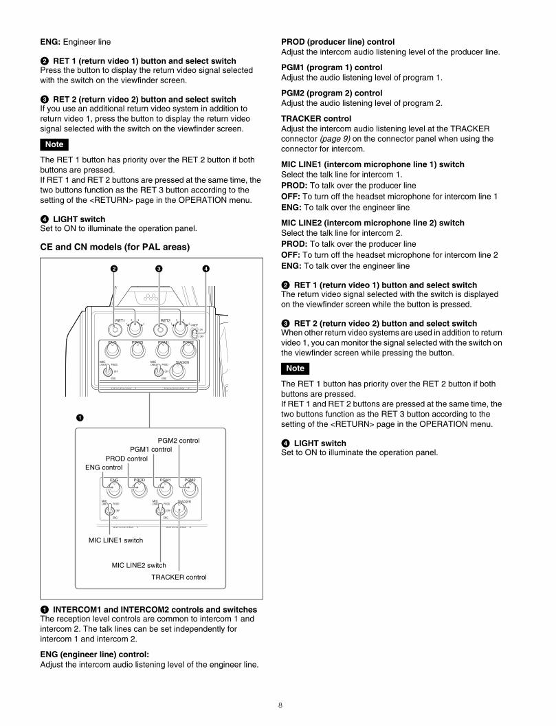
a INTERCOM1 and INTERCOM2 controls and switchesThe reception level controls are common to intercom 1 and intercom 2. The talk lines can be set independently for intercom 1 and intercom 2.
ENG (engineer line) control: Adjust the intercom audio listening level of the engineer line.
PROD (producer line) controlAdjust the intercom audio listening level of the producer line.
PGM1 (program 1) controlAdjust the audio listening level of program 1.
PGM2 (program 2) controlAdjust the audio listening level of program 2.
TRACKER controlAdjust the intercom audio listening level at the TRACKER connector (page 9) on the connector panel when using the connector for intercom.
MIC LINE1 (intercom microphone line 1) switchSelect the talk line for intercom 1.PROD: To talk over the producer lineOFF: To turn off the headset microphone for intercom line 1ENG: To talk over the engineer line
MIC LINE2 (intercom microphone line 2) switchSelect the talk line for intercom 2.PROD: To talk over the producer lineOFF: To turn off the headset microphone for intercom line 2ENG: To talk over the engineer line
b RET 1 (return video 1) button and select switchThe return video signal selected with the switch is displayed on the viewfinder screen while the button is pressed.
c RET 2 (return video 2) button and select switchWhen other return video systems are used in addition to return video 1, you can monitor the signal selected with the switch on the viewfinder screen while pressing the button.
The RET 1 button has priority over the RET 2 button if both buttons are pressed.If RET 1 and RET 2 buttons are pressed at the same time, the two buttons function as the RET 3 button according to the setting of the <RETURN> page in the OPERATION menu.
d LIGHT switchSet to ON to illuminate the operation panel.
Note
PGM1 control PGM2 control
MIC LINE1 switch
TRACKER control
ENG control PROD control
MIC LINE2 switch
a
2 3 4
Note
8
Connector panel
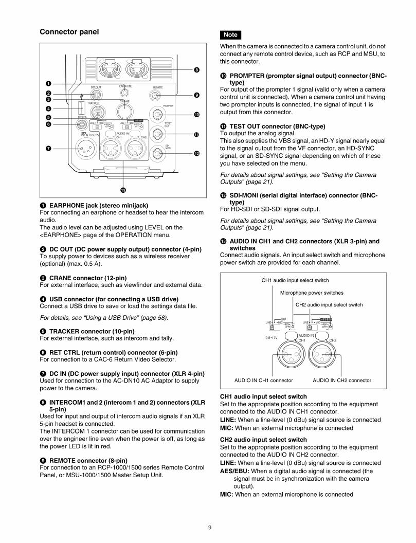
a EARPHONE jack (stereo minijack)For connecting an earphone or headset to hear the intercom audio.The audio level can be adjusted using LEVEL on the <EARPHONE> page of the OPERATION menu.
b DC OUT (DC power supply output) connector (4-pin)To supply power to devices such as a wireless receiver (optional) (max. 0.5 A).
c CRANE connector (12-pin)For external interface, such as viewfinder and external data.
d USB connector (for connecting a USB drive)Connect a USB drive to save or load the settings data file.
For details, see “Using a USB Drive” (page 58).
e TRACKER connector (10-pin)For external interface, such as intercom and tally.
f RET CTRL (return control) connector (6-pin)For connection to a CAC-6 Return Video Selector.
g DC IN (DC power supply input) connector (XLR 4-pin)Used for connection to the AC-DN10 AC Adaptor to supply power to the camera.
h INTERCOM1 and 2 (intercom 1 and 2) connectors (XLR 5-pin)
Used for input and output of intercom audio signals if an XLR 5-pin headset is connected.The INTERCOM 1 connector can be used for communication over the engineer line even when the power is off, as long as the power LED is lit in red.
i REMOTE connector (8-pin)For connection to an RCP-1000/1500 series Remote Control Panel, or MSU-1000/1500 Master Setup Unit.
When the camera is connected to a camera control unit, do not connect any remote control device, such as RCP and MSU, to this connector.
j PROMPTER (prompter signal output) connector (BNC-type)
For output of the prompter 1 signal (valid only when a camera control unit is connected). When a camera control unit having two prompter inputs is connected, the signal of input 1 is output from this connector.
k TEST OUT connector (BNC-type)To output the analog signal.This also supplies the VBS signal, an HD-Y signal nearly equal to the signal output from the VF connector, an HD-SYNC signal, or an SD-SYNC signal depending on which of these you have selected on the menu.
For details about signal settings, see “Setting the Camera Outputs” (page 21).
l SDI-MONI (serial digital interface) connector (BNC-type)
For HD-SDI or SD-SDI signal output.
For details about signal settings, see “Setting the Camera Outputs” (page 21).
m AUDIO IN CH1 and CH2 connectors (XLR 3-pin) and switches
Connect audio signals. An input select switch and microphone power switch are provided for each channel.
CH1 audio input select switchSet to the appropriate position according to the equipment connected to the AUDIO IN CH1 connector.LINE: When a line-level (0 dBu) signal source is connectedMIC: When an external microphone is connected
CH2 audio input select switchSet to the appropriate position according to the equipment connected to the AUDIO IN CH2 connector.LINE: When a line-level (0 dBu) signal source is connectedAES/EBU: When a digital audio signal is connected (the
signal must be in synchronization with the camera output).
MIC: When an external microphone is connected
bc
d
ef
g
h
i
j
k
a
l
m
Note
CH1 audio input select switch
Microphone power switches
CH2 audio input select switch
AUDIO IN CH2 connectorAUDIO IN CH1 connector
9
Microphone power switchesWhen a microphone is connected to the corresponding AUDIO IN connector, set whether or not to supply a power to the microphone.+48V: To supply +48 V power supply.OFF: Not to supply power.(No function has been assigned to the lowermost position. No power is supplied to the microphone.)
To supply +12 V power, contact a Sony sales representative or Sony service representative.
Preparations
Attaching a Lens
For information on handling lenses, refer to the lens’ operation manual.
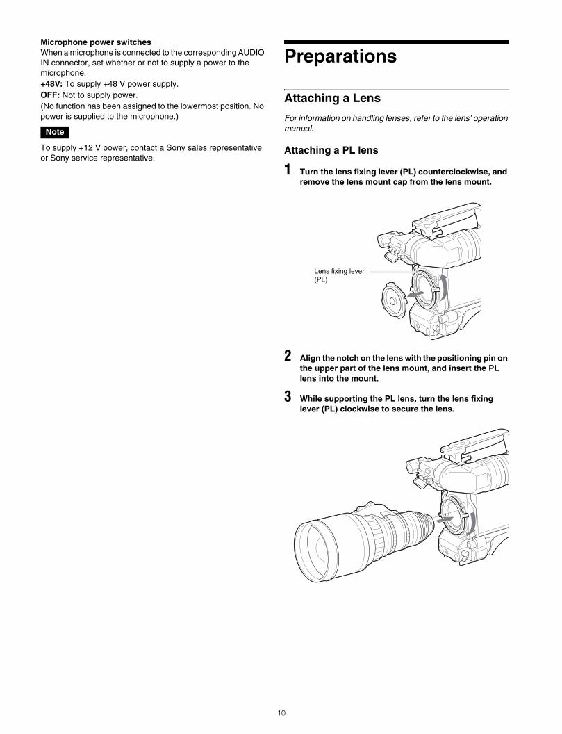
Attaching a PL lens
1 Turn the lens fixing lever (PL) counterclockwise, and remove the lens mount cap from the lens mount.
2 Align the notch on the lens with the positioning pin on the upper part of the lens mount, and insert the PL lens into the mount.
3 While supporting the PL lens, turn the lens fixing lever (PL) clockwise to secure the lens.
Note
Lens fixing lever (PL)
10
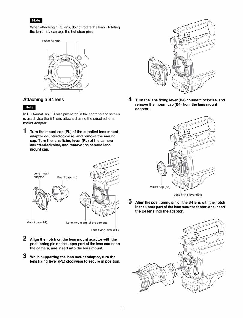
When attaching a PL lens, do not rotate the lens. Rotating the lens may damage the hot shoe pins.
Attaching a B4 lens
In HD format, an HD-size pixel area in the center of the screen is used. Use the B4 lens attached using the supplied lens mount adaptor.
1 Turn the mount cap (PL) of the supplied lens mount adaptor counterclockwise, and remove the mount cap. Turn the lens fixing lever (PL) of the camera counterclockwise, and remove the camera lens mount cap.
2 Align the notch on the lens mount adaptor with the positioning pin on the upper part of the lens mount on the camera, and insert into the lens mount.
3 While supporting the lens mount adaptor, turn the lens fixing lever (PL) clockwise to secure in position.
4 Turn the lens fixing lever (B4) counterclockwise, and remove the mount cap (B4) from the lens mount adaptor.
5 Align the positioning pin on the B4 lens with the notch in the upper part of the lens mount adaptor, and insert the B4 lens into the adaptor.
Note
Note
Hot shoe pins
Lens mount cap of the cameraMount cap (B4)
Mount cap (PL)Lens mount adaptor
Lens fixing lever (PL)
Lens fixing lever (B4)
Mount cap (B4)
11
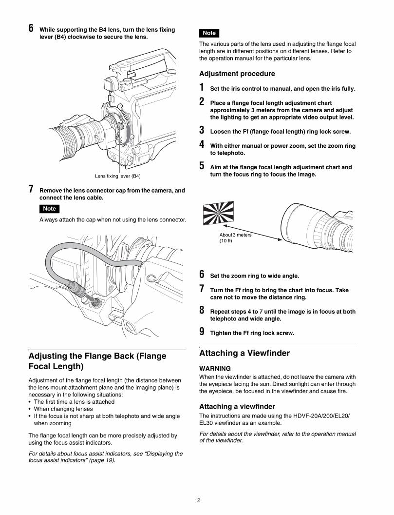
6 While supporting the B4 lens, turn the lens fixing lever (B4) clockwise to secure the lens.
7 Remove the lens connector cap from the camera, and connect the lens cable.
Always attach the cap when not using the lens connector.
Adjusting the Flange Back (Flange Focal Length)
Adjustment of the flange focal length (the distance between the lens mount attachment plane and the imaging plane) is necessary in the following situations:• The first time a lens is attached• When changing lenses• If the focus is not sharp at both telephoto and wide angle
when zooming
The flange focal length can be more precisely adjusted by using the focus assist indicators.
For details about focus assist indicators, see “Displaying the focus assist indicators” (page 19).
The various parts of the lens used in adjusting the flange focal length are in different positions on different lenses. Refer to the operation manual for the particular lens.
Adjustment procedure
1 Set the iris control to manual, and open the iris fully.
2 Place a flange focal length adjustment chart approximately 3 meters from the camera and adjust the lighting to get an appropriate video output level.
3 Loosen the Ff (flange focal length) ring lock screw.
4 With either manual or power zoom, set the zoom ring to telephoto.
5 Aim at the flange focal length adjustment chart and turn the focus ring to focus the image.
6 Set the zoom ring to wide angle.
7 Turn the Ff ring to bring the chart into focus. Take care not to move the distance ring.
8 Repeat steps 4 to 7 until the image is in focus at both telephoto and wide angle.
9 Tighten the Ff ring lock screw.
Attaching a Viewfinder
WARNINGWhen the viewfinder is attached, do not leave the camera with the eyepiece facing the sun. Direct sunlight can enter through the eyepiece, be focused in the viewfinder and cause fire.
Attaching a viewfinderThe instructions are made using the HDVF-20A/200/EL20/EL30 viewfinder as an example.
For details about the viewfinder, refer to the operation manual of the viewfinder.
Note
Lens fixing lever (B4)
Note
About 3 meters (10 ft)
12
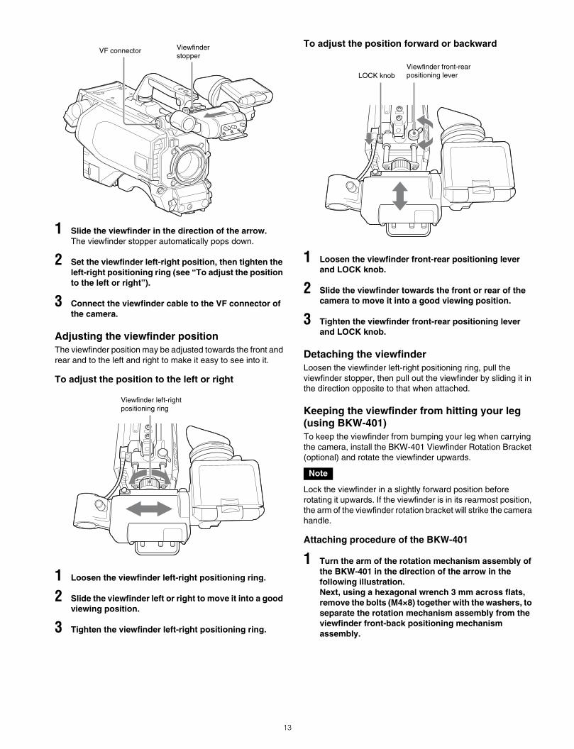
1 Slide the viewfinder in the direction of the arrow.The viewfinder stopper automatically pops down.
2 Set the viewfinder left-right position, then tighten the left-right positioning ring (see “To adjust the position to the left or right”).
3 Connect the viewfinder cable to the VF connector of the camera.
Adjusting the viewfinder positionThe viewfinder position may be adjusted towards the front and rear and to the left and right to make it easy to see into it.
To adjust the position to the left or right
1 Loosen the viewfinder left-right positioning ring.
2 Slide the viewfinder left or right to move it into a good viewing position.
3 Tighten the viewfinder left-right positioning ring.
To adjust the position forward or backward
1 Loosen the viewfinder front-rear positioning lever and LOCK knob.
2 Slide the viewfinder towards the front or rear of the camera to move it into a good viewing position.
3 Tighten the viewfinder front-rear positioning lever and LOCK knob.
Detaching the viewfinderLoosen the viewfinder left-right positioning ring, pull the viewfinder stopper, then pull out the viewfinder by sliding it in the direction opposite to that when attached.
Keeping the viewfinder from hitting your leg (using BKW-401)To keep the viewfinder from bumping your leg when carrying the camera, install the BKW-401 Viewfinder Rotation Bracket (optional) and rotate the viewfinder upwards.
Lock the viewfinder in a slightly forward position before rotating it upwards. If the viewfinder is in its rearmost position, the arm of the viewfinder rotation bracket will strike the camera handle.
Attaching procedure of the BKW-401
1 Turn the arm of the rotation mechanism assembly of the BKW-401 in the direction of the arrow in the following illustration.Next, using a hexagonal wrench 3 mm across flats, remove the bolts (M4×8) together with the washers, to separate the rotation mechanism assembly from the viewfinder front-back positioning mechanism assembly.
Viewfinderstopper
VF connector
Viewfinder left-right positioning ring
Note
Viewfinder front-rear positioning leverLOCK knob
13
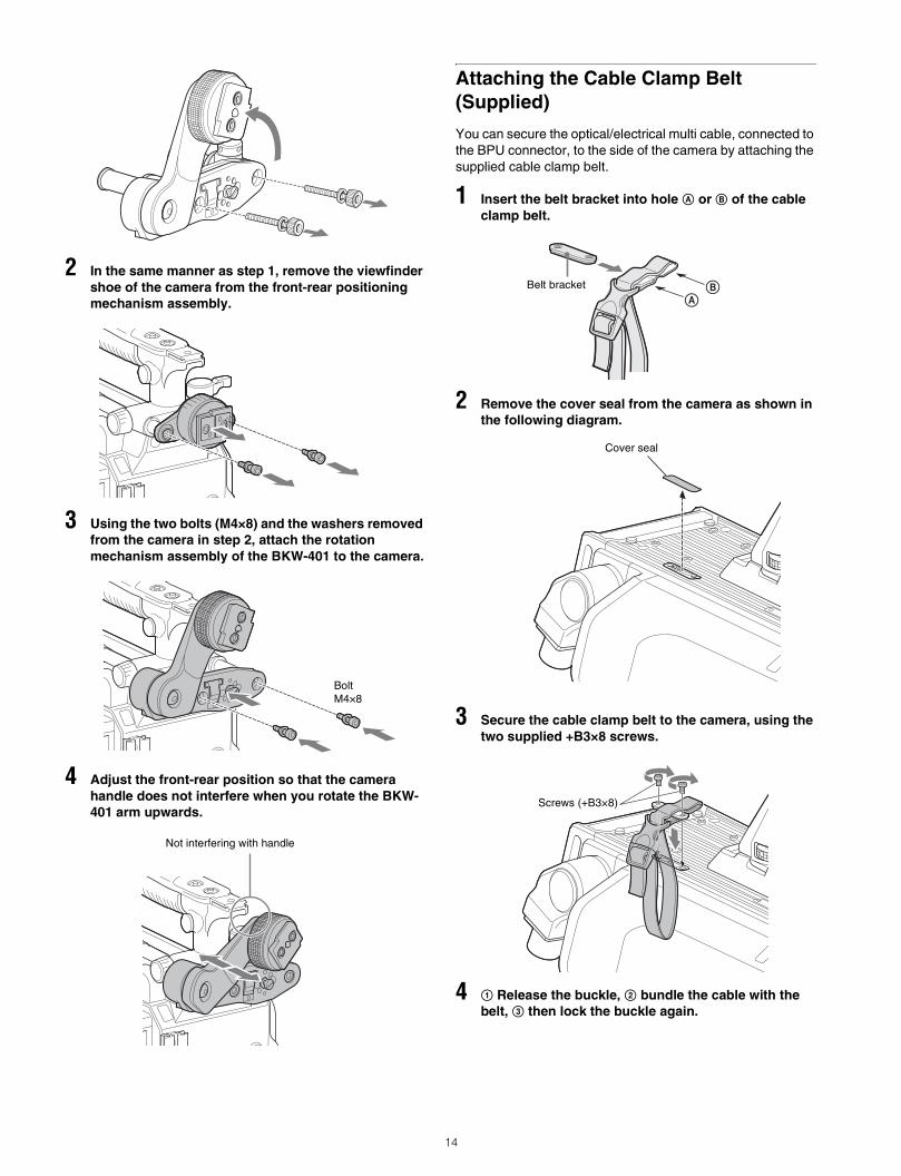
2 In the same manner as step 1, remove the viewfinder shoe of the camera from the front-rear positioning mechanism assembly.
3 Using the two bolts (M4×8) and the washers removed from the camera in step 2, attach the rotation mechanism assembly of the BKW-401 to the camera.
4 Adjust the front-rear position so that the camera handle does not interfere when you rotate the BKW-401 arm upwards.
Attaching the Cable Clamp Belt (Supplied)
You can secure the optical/electrical multi cable, connected to the BPU connector, to the side of the camera by attaching the supplied cable clamp belt.
1 Insert the belt bracket into hole A or B of the cable clamp belt.
2 Remove the cover seal from the camera as shown in the following diagram.
3 Secure the cable clamp belt to the camera, using the two supplied +B3×8 screws.
4 1 Release the buckle, 2 bundle the cable with the belt, 3 then lock the buckle again.
BoltM4×8
Not interfering with handle
ABBelt bracket
Cover seal
Screws (+B3×8)
14
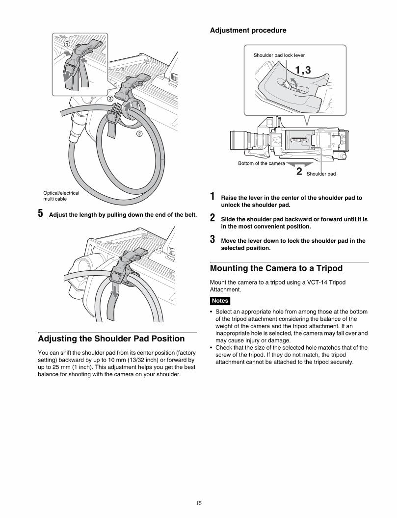
5 Adjust the length by pulling down the end of the belt.
Adjusting the Shoulder Pad Position
You can shift the shoulder pad from its center position (factory setting) backward by up to 10 mm (13/32 inch) or forward by up to 25 mm (1 inch). This adjustment helps you get the best balance for shooting with the camera on your shoulder.
Adjustment procedure
1 Raise the lever in the center of the shoulder pad to unlock the shoulder pad.
2 Slide the shoulder pad backward or forward until it is in the most convenient position.
3 Move the lever down to lock the shoulder pad in the selected position.
Mounting the Camera to a Tripod
Mount the camera to a tripod using a VCT-14 Tripod Attachment.
• Select an appropriate hole from among those at the bottom of the tripod attachment considering the balance of the weight of the camera and the tripod attachment. If an inappropriate hole is selected, the camera may fall over and may cause injury or damage.
• Check that the size of the selected hole matches that of the screw of the tripod. If they do not match, the tripod attachment cannot be attached to the tripod securely.
Optical/electrical multi cable
Notes
1,3
2 Shoulder pad
Bottom of the camera
Shoulder pad lock lever
15
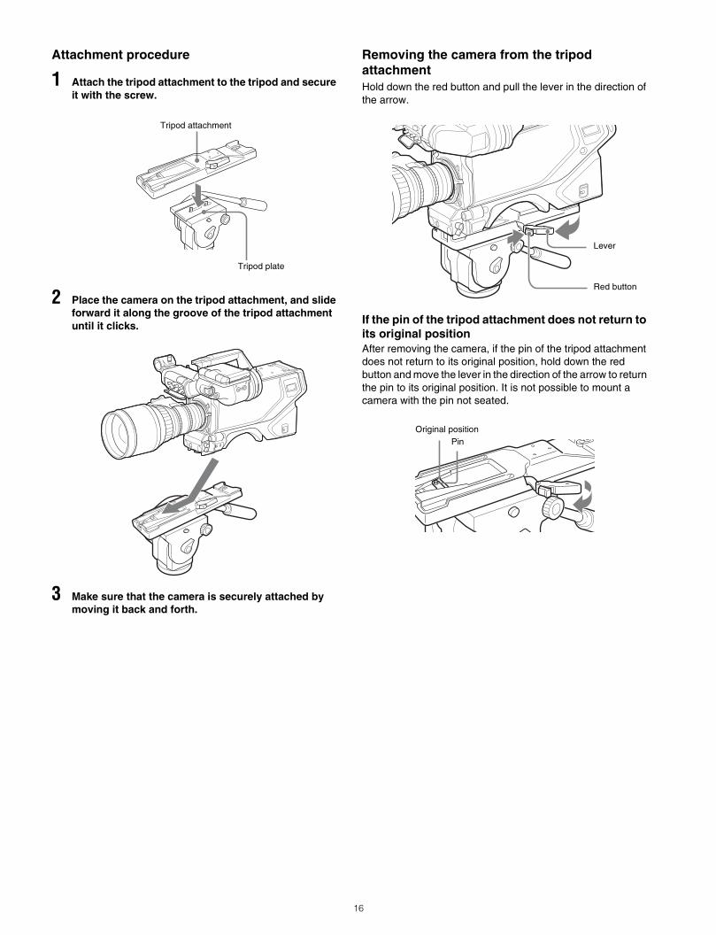
Attachment procedure
1 Attach the tripod attachment to the tripod and secure it with the screw.
2 Place the camera on the tripod attachment, and slide forward it along the groove of the tripod attachment until it clicks.
3 Make sure that the camera is securely attached by moving it back and forth.
Removing the camera from the tripod attachmentHold down the red button and pull the lever in the direction of the arrow.
If the pin of the tripod attachment does not return to its original positionAfter removing the camera, if the pin of the tripod attachment does not return to its original position, hold down the red button and move the lever in the direction of the arrow to return the pin to its original position. It is not possible to mount a camera with the pin not seated.
Tripod attachment
Tripod plate
Red button
Lever
PinOriginal position
16

Adjustments and Settings for Shooting
Adjusting the Black Balance and White Balance
In order to maintain high picture quality, it is necessary to set the black balance and white balance appropriately for the conditions.
Black balance adjustmentThe black balance needs adjustment in situations like the following:• The first time the camera is used• When the camera is used after a long period of disuse• When the surrounding temperature changes greatly• When the gain value is changed using the setup menusNormally, there is no need to adjust the black balance every time the camera is turned on.
White balance adjustmentAlways readjust the white balance when lighting conditions change.
About the viewfinder screenAfter the process of adjusting the black balance or white balance begins, messages about the progress and results of the adjustment will be displayed on the viewfinder screen.
Adjusted values set through automatic adjustment, and other settings, are stored in the camera’s memory and preserved even when the camera power is turned off.
Adjusting the black balanceExecute auto black balance (ABB) adjustment from the MSU or RCP.Automatic adjustment of black balance begins.In automatic adjustment of black balance, both the black set and black balance are adjusted.During adjustment, a message like the one in the figure below will be displayed on the viewfinder screen.
When the adjustment process is completed, the message “ABB : OK” will be displayed. The adjusted value is automatically stored in memory.
• During black balance adjustment, the iris will be automatically closed.
• During black balance adjustment, the gain switching circuit will work automatically, and the viewfinder screen will flicker several times. This is not a malfunction.
• If not in a completely shielded environment, attach the lens cap and then execute auto black balance (ABB) adjustment.
When automatic black balance adjustment failsIf the automatic black balance adjustment process does not end successfully, the error message “ABB : NG” will be displayed on the viewfinder screen for approximately three seconds.If this error message is displayed, try black balance adjustment again.If the error message continues to be displayed after several attempts, the camera requires internal inspection.
About black balance memoryThe black balance values stored in memory will be preserved even when the camera power is turned off.
Adjusting the white balance
1 Execute auto white balance (AWB) adjustment from the MSU or RCP.
2 Select the filter setting according to the lighting conditions.
To select the ND filterPress the ND filter select button while holding the FILTER LOCAL button depressed.Each press of the select button switches the available ND filters (clear, 1/4 ND, 1/16 ND) in sequence.
To select the CC (color temperature conversion) filterPress the CC filter select button while holding the FILTER LOCAL button depressed.Each press of the select button switches the available CC filters (3200K, 4300K, 6300K) in sequence.
Note
Notes
ABB:EXECUTING
ND filter Color temperature conversion filter
1 Clear A 3200K (clear)
FILTER LOCAL button
ND filter select button
CC filter select button
17
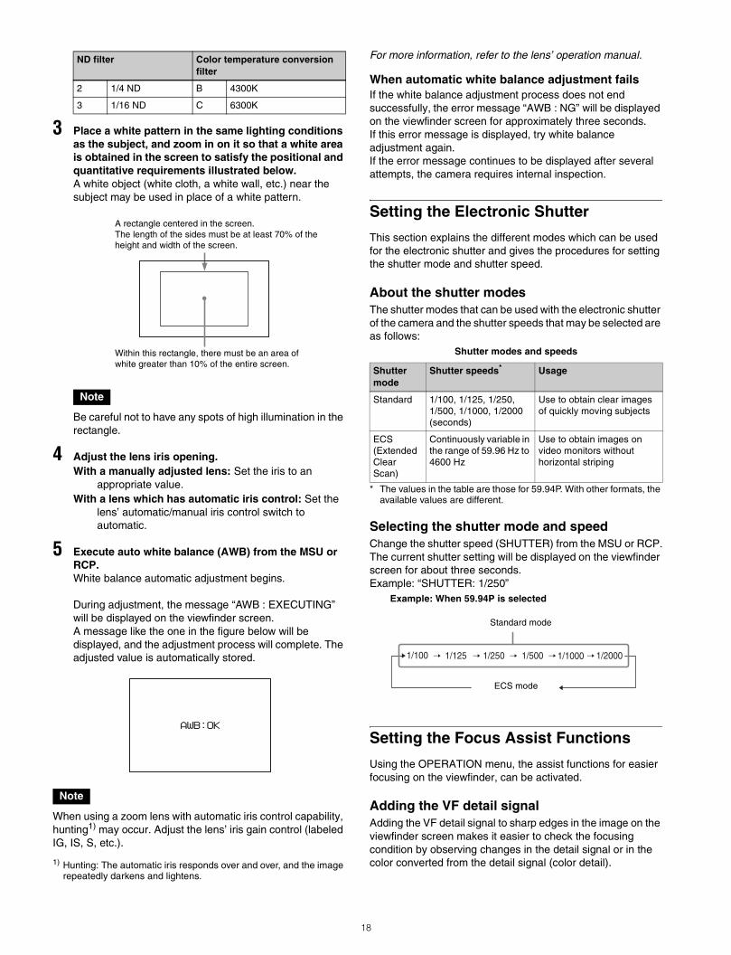
3 Place a white pattern in the same lighting conditions as the subject, and zoom in on it so that a white area is obtained in the screen to satisfy the positional and quantitative requirements illustrated below.A white object (white cloth, a white wall, etc.) near the subject may be used in place of a white pattern.
Be careful not to have any spots of high illumination in the rectangle.
4 Adjust the lens iris opening.With a manually adjusted lens: Set the iris to an
appropriate value.With a lens which has automatic iris control: Set the
lens’ automatic/manual iris control switch to automatic.
5 Execute auto white balance (AWB) from the MSU or RCP.White balance automatic adjustment begins.
During adjustment, the message “AWB : EXECUTING” will be displayed on the viewfinder screen.A message like the one in the figure below will be displayed, and the adjustment process will complete. The adjusted value is automatically stored.
When using a zoom lens with automatic iris control capability, hunting1) may occur. Adjust the lens’ iris gain control (labeled IG, IS, S, etc.).
1) Hunting: The automatic iris responds over and over, and the image repeatedly darkens and lightens.
For more information, refer to the lens’ operation manual.
When automatic white balance adjustment failsIf the white balance adjustment process does not end successfully, the error message “AWB : NG” will be displayed on the viewfinder screen for approximately three seconds.If this error message is displayed, try white balance adjustment again.If the error message continues to be displayed after several attempts, the camera requires internal inspection.
Setting the Electronic Shutter
This section explains the different modes which can be used for the electronic shutter and gives the procedures for setting the shutter mode and shutter speed.
About the shutter modesThe shutter modes that can be used with the electronic shutter of the camera and the shutter speeds that may be selected are as follows:
* The values in the table are those for 59.94P. With other formats, the available values are different.
Selecting the shutter mode and speedChange the shutter speed (SHUTTER) from the MSU or RCP.The current shutter setting will be displayed on the viewfinder screen for about three seconds.Example: “SHUTTER: 1/250”
Example: When 59.94P is selected
Setting the Focus Assist Functions
Using the OPERATION menu, the assist functions for easier focusing on the viewfinder, can be activated.
Adding the VF detail signalAdding the VF detail signal to sharp edges in the image on the viewfinder screen makes it easier to check the focusing condition by observing changes in the detail signal or in the color converted from the detail signal (color detail).
2 1/4 ND B 4300K
3 1/16 ND C 6300K
Note
Note
ND filter Color temperature conversion filter
A rectangle centered in the screen.The length of the sides must be at least 70% of the height and width of the screen.
Within this rectangle, there must be an area of white greater than 10% of the entire screen.
AWB:OK
Shutter modes and speeds
Shutter mode
Shutter speeds* Usage
Standard 1/100, 1/125, 1/250,1/500, 1/1000, 1/2000 (seconds)
Use to obtain clear images of quickly moving subjects
ECS (Extended Clear Scan)
Continuously variable in the range of 59.96 Hz to 4600 Hz
Use to obtain images on video monitors without horizontal striping
1/100 1/20001/10001/5001/2501/125
Standard mode
ECS mode
18
The focus setting where the detail signal becomes strongest is the best focus setting.
1 Turn on the camera.
2 Set the DISPLAY switch to MENU while holding the MENU SEL knob/ENTER button pressed.The camera enters Menu mode, and “TOP” is displayed at the upper right corner of the screen.
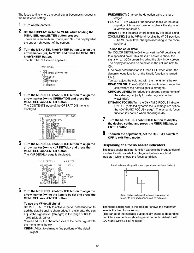
3 Turn the MENU SEL knob/ENTER button to align the arrow marker (,) to “TOP” and press the MENU SEL knob/ENTER button.The TOP MENU screen appears.
4 Turn the MENU SEL knob/ENTER button to align the arrow marker (,) to OPERATION and press the MENU SEL knob/ENTER button.The CONTENTS page of the OPERATION menu is displayed.
5 Turn the MENU SEL knob/ENTER button to align the arrow marker (,) to <VF DETAIL> and press the MENU SEL knob/ENTER button.The <VF DETAIL> page is displayed.
6 Turn the MENU SEL knob/ENTER button to align the arrow marker (,) to the item to be set and press the MENU SEL knob/ENTER button.
To use the VF detail signalSet VF DETAIL to ON to activate the VF detail function to add the detail signal to sharp edges in the image. You can adjust the signal level (strength) in the range of 0% to 100% (default: 25%).You can adjust the characteristics of the detail signal with the menu items below.CRISP: Adjust to eliminate fine portions of the detail
signal.
FREQUENCY: Change the detection band of sharp edges.
FLICKER: Turn ON/OFF the function to flicker the detail signal, which makes it easier to check the signal on a viewfinder screen.
AREA: To limit the area where to display the detail signal.ZOOM LINK: Set the VF detail level at the WIDE position.
(The VF detail level changes according to the zoom position.)
To use the color detailSet COLOR DETAIL to ON to convert the VF detail signal to a specified color. This makes it easier to check the signal on an LCD screen, including the viewfinder screen. The display color can be selected in the column next to ON.(The color detail function is turned OFF when either the dynamic focus function or the kinetic function is turned ON.)You can adjust the coloring with the menu items below.PEAK COLOR: Turn ON/OFF the function to change the
color where the detail signal is strongest.CHROMA LEVEL: To reduce the chroma components of
the video signal (only for video signals on the viewfinder).
DYNAMIC FOCUS: Turn the DYNAMIC FOCUS indicator ON/OFF (detailed dynamic focus settings are set on the <DYNAMIC FOCUS> page). The dynamic focus function is enabled when shooting in 4K.
7 Turn the MENU SEL knob/ENTER button to display the desired setting and press the MENU SEL knob/ENTER button.
8 To finish the adjustment, set the DISPLAY switch to OFF to exit Menu mode.
Displaying the focus assist indicatorsThe focus assist indicator function extracts the irregularities of a subject and converts the integrated values to a level indicator, which shows the focus condition.
The focus setting where the indicator shows the maximum level is the best focus setting.(The range of the indicator substantially changes depending on picture elements or shooting environments. Adjust it with GAIN and OFFSET as required.)
<TOP MENU>
USER
USER MENU CUSTOMIZE
ALL
OPERATION
PAINT
MAINTENANCE
FILE
DIAGNOSIS
CONTENTS 00 TOP
01.<VF DISPLAY>
02.<'!'IND>
03.<VF MARKER>
04.<VF DETAIL>
05.<DYNAMIC FOCUS>
06.<FOCUS POSITION METER1>
07.<FOCUS POSITION METER2>
08.<FOLLOW FOCUS>
09.<FOCUS ASSIST>
10.<ZEBRA>
<VF DETAIL> 04 TOP
VF DETAIL : ON (25%)
CRISP : 0
FREQUENCY: 9M
FLICKER : OFF
AREA : 100%
ZOOM LINK: ON 50%
COLOR DETAIL : OFF BLUE
PEAK COLOR : OFF
CHROMA LEVEL: 25%
DYNAMIC FOCUS: OFF
Level indicator (its position and operations can be adjusted.)
Area marker to display the detection area of the focus (its size and position can be adjusted.)
19
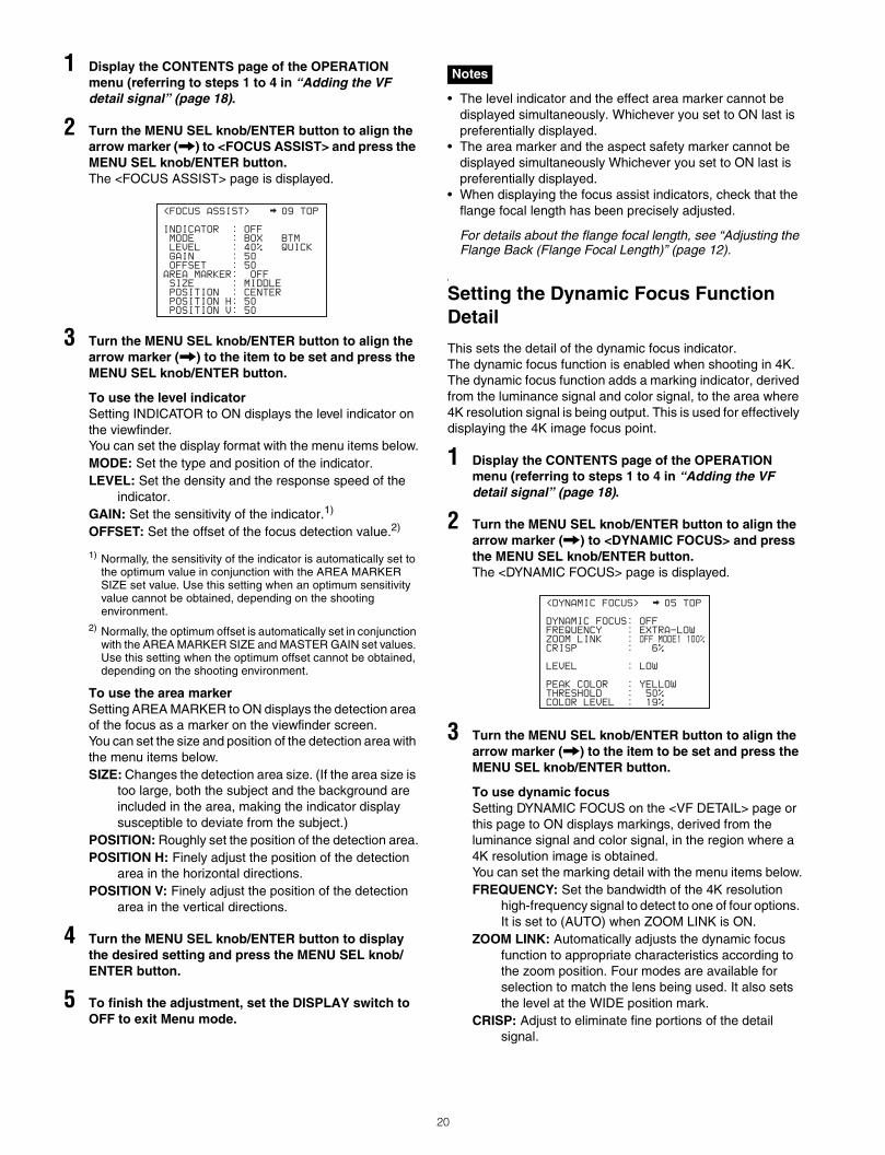
1 Display the CONTENTS page of the OPERATION menu (referring to steps 1 to 4 in “Adding the VF detail signal” (page 18).
2 Turn the MENU SEL knob/ENTER button to align the arrow marker (,) to <FOCUS ASSIST> and press the MENU SEL knob/ENTER button.The <FOCUS ASSIST> page is displayed.
3 Turn the MENU SEL knob/ENTER button to align the arrow marker (,) to the item to be set and press the MENU SEL knob/ENTER button.
To use the level indicatorSetting INDICATOR to ON displays the level indicator on the viewfinder.You can set the display format with the menu items below.MODE: Set the type and position of the indicator.LEVEL: Set the density and the response speed of the
indicator.GAIN: Set the sensitivity of the indicator.1)
OFFSET: Set the offset of the focus detection value.2)
1) Normally, the sensitivity of the indicator is automatically set to the optimum value in conjunction with the AREA MARKER SIZE set value. Use this setting when an optimum sensitivity value cannot be obtained, depending on the shooting environment.
2) Normally, the optimum offset is automatically set in conjunction with the AREA MARKER SIZE and MASTER GAIN set values. Use this setting when the optimum offset cannot be obtained, depending on the shooting environment.
To use the area markerSetting AREA MARKER to ON displays the detection area of the focus as a marker on the viewfinder screen.You can set the size and position of the detection area with the menu items below.SIZE: Changes the detection area size. (If the area size is
too large, both the subject and the background are included in the area, making the indicator display susceptible to deviate from the subject.)
POSITION: Roughly set the position of the detection area.POSITION H: Finely adjust the position of the detection
area in the horizontal directions.POSITION V: Finely adjust the position of the detection
area in the vertical directions.
4 Turn the MENU SEL knob/ENTER button to display the desired setting and press the MENU SEL knob/ENTER button.
5 To finish the adjustment, set the DISPLAY switch to OFF to exit Menu mode.
• The level indicator and the effect area marker cannot be displayed simultaneously. Whichever you set to ON last is preferentially displayed.
• The area marker and the aspect safety marker cannot be displayed simultaneously Whichever you set to ON last is preferentially displayed.
• When displaying the focus assist indicators, check that the flange focal length has been precisely adjusted.
For details about the flange focal length, see “Adjusting the Flange Back (Flange Focal Length)” (page 12).
Setting the Dynamic Focus Function Detail
This sets the detail of the dynamic focus indicator.The dynamic focus function is enabled when shooting in 4K.The dynamic focus function adds a marking indicator, derived from the luminance signal and color signal, to the area where 4K resolution signal is being output. This is used for effectively displaying the 4K image focus point.
1 Display the CONTENTS page of the OPERATION menu (referring to steps 1 to 4 in “Adding the VF detail signal” (page 18).
2 Turn the MENU SEL knob/ENTER button to align the arrow marker (,) to <DYNAMIC FOCUS> and press the MENU SEL knob/ENTER button.The <DYNAMIC FOCUS> page is displayed.
3 Turn the MENU SEL knob/ENTER button to align the arrow marker (,) to the item to be set and press the MENU SEL knob/ENTER button.
To use dynamic focusSetting DYNAMIC FOCUS on the <VF DETAIL> page or this page to ON displays markings, derived from the luminance signal and color signal, in the region where a 4K resolution image is obtained.You can set the marking detail with the menu items below.FREQUENCY: Set the bandwidth of the 4K resolution
high-frequency signal to detect to one of four options. It is set to (AUTO) when ZOOM LINK is ON.
ZOOM LINK: Automatically adjusts the dynamic focus function to appropriate characteristics according to the zoom position. Four modes are available for selection to match the lens being used. It also sets the level at the WIDE position mark.
CRISP: Adjust to eliminate fine portions of the detail signal.
<FOCUS ASSIST> 09 TOP
INDICATOR : OFF
MODE : BOX BTM
LEVEL : 40% QUICK
GAIN : 50
OFFSET : 50
AREA MARKER: OFF
SIZE : MIDDLE
POSITION : CENTER
POSITION H: 50
POSITION V: 50
Notes
<DYNAMIC FOCUS> 05 TOP
DYNAMIC FOCUS: OFF
FREQUENCY : EXTRA-LOW
ZOOM LINK : OFF MODE1 100%
CRISP : 6%
LEVEL : LOW
PEAK COLOR : YELLOW
THRESHOLD : 50%
COLOR LEVEL : 19%
20
LEVEL: Set the brightness level of the marking signal to add.
PEAK COLOR: Set the color added to the marking indicator where the detected value exceeds a fixed level.
THRESHOLD: Set the threshold value for displaying PEAK COLOR.
COLOR LEVEL: Set the saturation of the color of the PEAK COLOR indicator.
4 Turn the MENU SEL knob/ENTER button to display the desired setting and press the MENU SEL knob/ENTER button.
5 To finish the adjustment, set the DISPLAY switch to OFF to exit Menu mode.
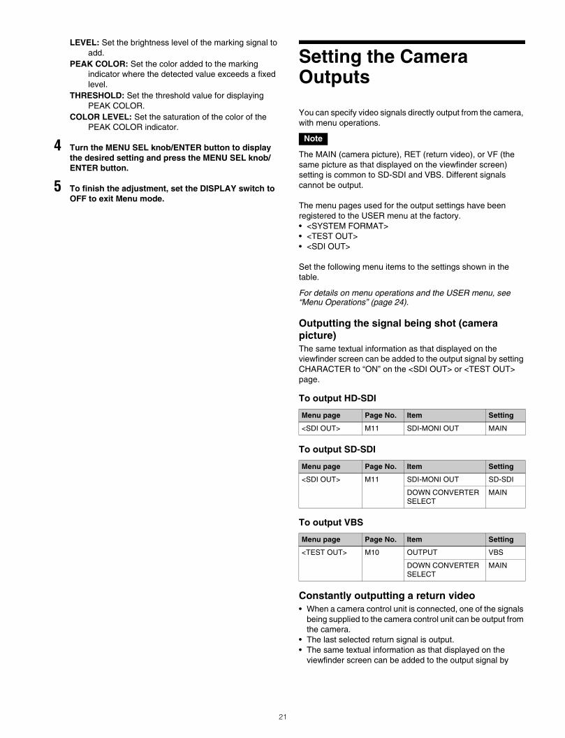
Setting the Camera Outputs
You can specify video signals directly output from the camera, with menu operations.
The MAIN (camera picture), RET (return video), or VF (the same picture as that displayed on the viewfinder screen) setting is common to SD-SDI and VBS. Different signals cannot be output.
The menu pages used for the output settings have been registered to the USER menu at the factory.• <SYSTEM FORMAT>• <TEST OUT>• <SDI OUT>
Set the following menu items to the settings shown in the table.
For details on menu operations and the USER menu, see “Menu Operations” (page 24).
Outputting the signal being shot (camera picture)The same textual information as that displayed on the viewfinder screen can be added to the output signal by setting CHARACTER to “ON” on the <SDI OUT> or <TEST OUT> page.
To output HD-SDI
To output SD-SDI
To output VBS
Constantly outputting a return video• When a camera control unit is connected, one of the signals
being supplied to the camera control unit can be output from the camera.
• The last selected return signal is output.• The same textual information as that displayed on the
viewfinder screen can be added to the output signal by
Note
Menu page Page No. Item Setting
<SDI OUT> M11 SDI-MONI OUT MAIN
Menu page Page No. Item Setting
<SDI OUT> M11 SDI-MONI OUT SD-SDI
DOWN CONVERTER SELECT
MAIN
Menu page Page No. Item Setting
<TEST OUT> M10 OUTPUT VBS
DOWN CONVERTER SELECT
MAIN
21
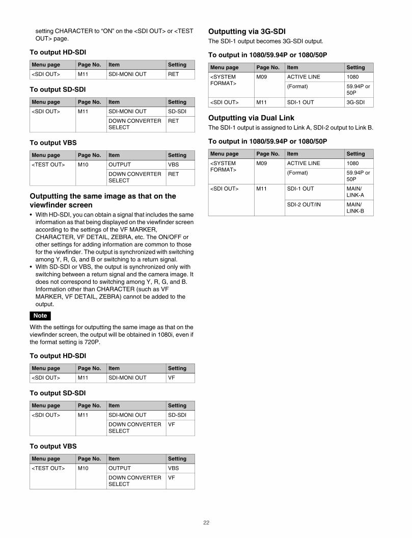
setting CHARACTER to “ON” on the <SDI OUT> or <TEST OUT> page.
To output HD-SDI
To output SD-SDI
To output VBS
Outputting the same image as that on the viewfinder screen• With HD-SDI, you can obtain a signal that includes the same
information as that being displayed on the viewfinder screen according to the settings of the VF MARKER, CHARACTER, VF DETAIL, ZEBRA, etc. The ON/OFF or other settings for adding information are common to those for the viewfinder. The output is synchronized with switching among Y, R, G, and B or switching to a return signal.
• With SD-SDI or VBS, the output is synchronized only with switching between a return signal and the camera image. It does not correspond to switching among Y, R, G, and B. Information other than CHARACTER (such as VF MARKER, VF DETAIL, ZEBRA) cannot be added to the output.
With the settings for outputting the same image as that on the viewfinder screen, the output will be obtained in 1080i, even if the format setting is 720P.
To output HD-SDI
To output SD-SDI
To output VBS
Outputting via 3G-SDIThe SDI-1 output becomes 3G-SDI output.
To output in 1080/59.94P or 1080/50P
Outputting via Dual LinkThe SDI-1 output is assigned to Link A, SDI-2 output to Link B.
To output in 1080/59.94P or 1080/50P
Menu page Page No. Item Setting
<SDI OUT> M11 SDI-MONI OUT RET
Menu page Page No. Item Setting
<SDI OUT> M11 SDI-MONI OUT SD-SDI
DOWN CONVERTER SELECT
RET
Menu page Page No. Item Setting
<TEST OUT> M10 OUTPUT VBS
DOWN CONVERTER SELECT
RET
Note
Menu page Page No. Item Setting
<SDI OUT> M11 SDI-MONI OUT VF
Menu page Page No. Item Setting
<SDI OUT> M11 SDI-MONI OUT SD-SDI
DOWN CONVERTER SELECT
VF
Menu page Page No. Item Setting
<TEST OUT> M10 OUTPUT VBS
DOWN CONVERTER SELECT
VF
Menu page Page No. Item Setting
<SYSTEM FORMAT>
M09 ACTIVE LINE 1080
(Format) 59.94P or 50P
<SDI OUT> M11 SDI-1 OUT 3G-SDI
Menu page Page No. Item Setting
<SYSTEM FORMAT>
M09 ACTIVE LINE 1080
(Format) 59.94P or 50P
<SDI OUT> M11 SDI-1 OUT MAIN/LINK-A
SDI-2 OUT/IN MAIN/LINK-B
22
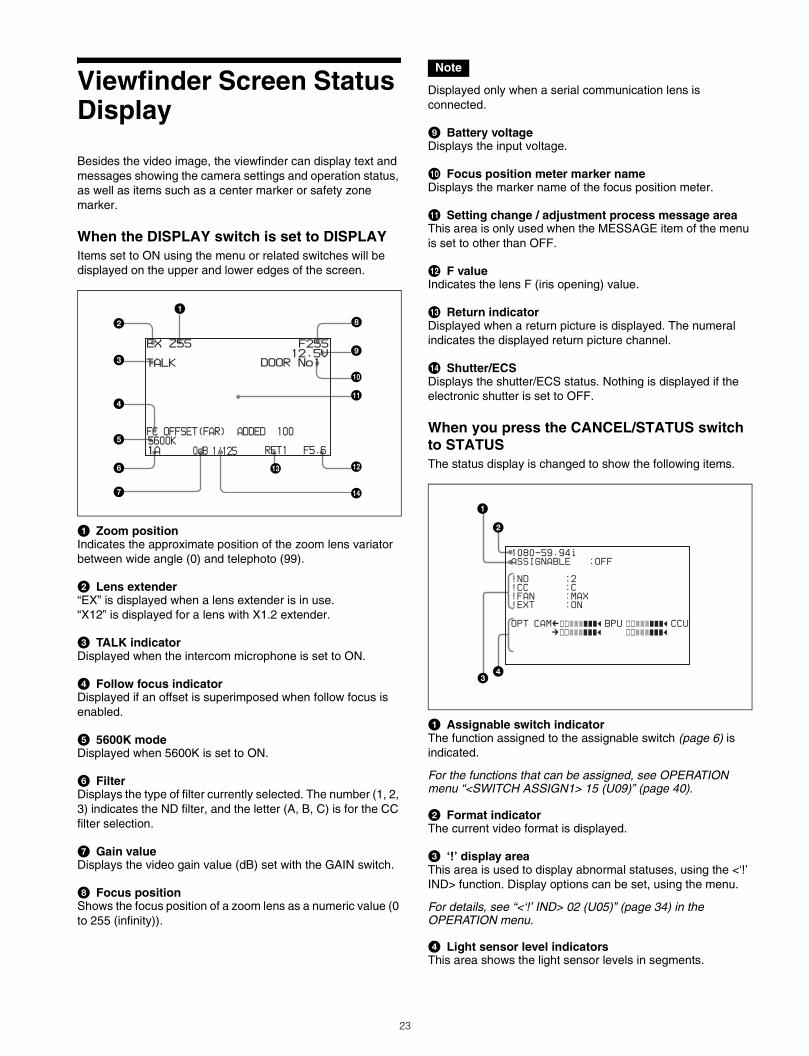
Viewfinder Screen Status Display
Besides the video image, the viewfinder can display text and messages showing the camera settings and operation status, as well as items such as a center marker or safety zone marker.
When the DISPLAY switch is set to DISPLAYItems set to ON using the menu or related switches will be displayed on the upper and lower edges of the screen.
a Zoom positionIndicates the approximate position of the zoom lens variator between wide angle (0) and telephoto (99).
b Lens extender“EX” is displayed when a lens extender is in use.“X12” is displayed for a lens with X1.2 extender.
c TALK indicatorDisplayed when the intercom microphone is set to ON.
d Follow focus indicatorDisplayed if an offset is superimposed when follow focus is enabled.
e 5600K modeDisplayed when 5600K is set to ON.
f FilterDisplays the type of filter currently selected. The number (1, 2, 3) indicates the ND filter, and the letter (A, B, C) is for the CC filter selection.
g Gain valueDisplays the video gain value (dB) set with the GAIN switch.
h Focus positionShows the focus position of a zoom lens as a numeric value (0 to 255 (infinity)).
Displayed only when a serial communication lens is connected.
i Battery voltageDisplays the input voltage.
j Focus position meter marker nameDisplays the marker name of the focus position meter.
k Setting change / adjustment process message areaThis area is only used when the MESSAGE item of the menu is set to other than OFF.
l F valueIndicates the lens F (iris opening) value.
m Return indicatorDisplayed when a return picture is displayed. The numeral indicates the displayed return picture channel.
n Shutter/ECSDisplays the shutter/ECS status. Nothing is displayed if the electronic shutter is set to OFF.
When you press the CANCEL/STATUS switch to STATUSThe status display is changed to show the following items.
a Assignable switch indicatorThe function assigned to the assignable switch (page 6) is indicated.
For the functions that can be assigned, see OPERATION menu “<SWITCH ASSIGN1> 15 (U09)” (page 40).
b Format indicatorThe current video format is displayed.
c ‘!’ display areaThis area is used to display abnormal statuses, using the <‘!’ IND> function. Display options can be set, using the menu.
For details, see “<‘!’ IND> 02 (U05)” (page 34) in the OPERATION menu.
d Light sensor level indicatorsThis area shows the light sensor levels in segments.
F255 12.5V
DOOR No1
EX Z55
1A F5.6RET15600K
TALK
FC OFFSET(FAR) ADDED 100
1/1250dB
a
d
e
f
g
h
i
j
k
l
b
c
m
n
Note
1080-59.94i
ASSIGNABLE :OFF
!ND :2
!CC :C
!FAN :MAX
!EXT :ON
OPT CAMCssxxxxxxb BPU ssxxxxxxb CCU
cssxxxxxxb ssxxxxxxb
a
cd
b
23
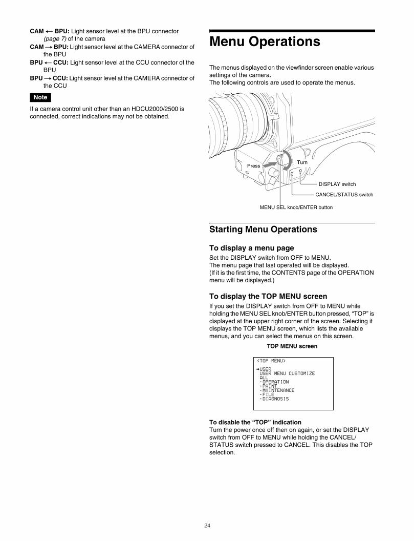
CAM T BPU: Light sensor level at the BPU connector (page 7) of the camera
CAM t BPU: Light sensor level at the CAMERA connector of the BPU
BPU T CCU: Light sensor level at the CCU connector of the BPU
BPU t CCU: Light sensor level at the CAMERA connector of the CCU
If a camera control unit other than an HDCU2000/2500 is connected, correct indications may not be obtained.
Menu Operations
The menus displayed on the viewfinder screen enable various settings of the camera.The following controls are used to operate the menus.
Starting Menu Operations
To display a menu pageSet the DISPLAY switch from OFF to MENU.The menu page that last operated will be displayed.(If it is the first time, the CONTENTS page of the OPERATION menu will be displayed.)
To display the TOP MENU screenIf you set the DISPLAY switch from OFF to MENU while holding the MENU SEL knob/ENTER button pressed, “TOP” is displayed at the upper right corner of the screen. Selecting it displays the TOP MENU screen, which lists the available menus, and you can select the menus on this screen.
TOP MENU screen
To disable the “TOP” indicationTurn the power once off then on again, or set the DISPLAY switch from OFF to MENU while holding the CANCEL/STATUS switch pressed to CANCEL. This disables the TOP selection.
Note
CANCEL/STATUS switch
DISPLAY switch
MENU SEL knob/ENTER button
PressTurn
<TOP MENU>
USER
USER MENU CUSTOMIZE
ALL
OPERATION
PAINT
MAINTENANCE
FILE
DIAGNOSIS
24
Available menus
USER menuThis menu can include menu pages selected from among the OPERATION, PAINT, MAINTENANCE, FILE, and DIAGNOSIS menus, for convenience. Changing, adding, and deleting pages can be performed with the USER MENU CUSTOMIZE menu.
USER MENU CUSTOMIZE menuThis menu allows you to edit the USER menu.
For details, see “Editing the USER Menu” (page 27).
ALL menuThis menu permits you to control all items of the OPERATION menu, PAINT menu, MAINTENANCE menu, FILE menu, and DIAGNOSIS menu as a single menu.
OPERATION menuThis menu contains items for camera operators to operate the camera. It mainly permits viewfinder, intercom, and switch settings.
PAINT menuThis menu contains items for making detailed image adjustments while using a waveform monitor to monitor the waveforms output from the camera. Support of a video engineer is usually required to use this menu.These item settings are mainly for use with an external remote control panel or master setup unit.
MAINTENANCE menuThis menu contains items for performing camera maintenance operations, such as changing the system or setting infrequently used “paint” items.
FILE menuThis menu is for performing file operations, such as writing or clearing the reference file.
DIAGNOSIS menuThis menu enables you to confirm the self-diagnostic information.
To select a menu on the TOP MENU screen
1 Turn the MENU SEL knob/ENTER button to align the arrow marker (,) with the desired menu indication.
2 Press the MENU SEL knob/ENTER button.The CONTENTS page or the last operated page of the selected menu is displayed.
Selecting Pages
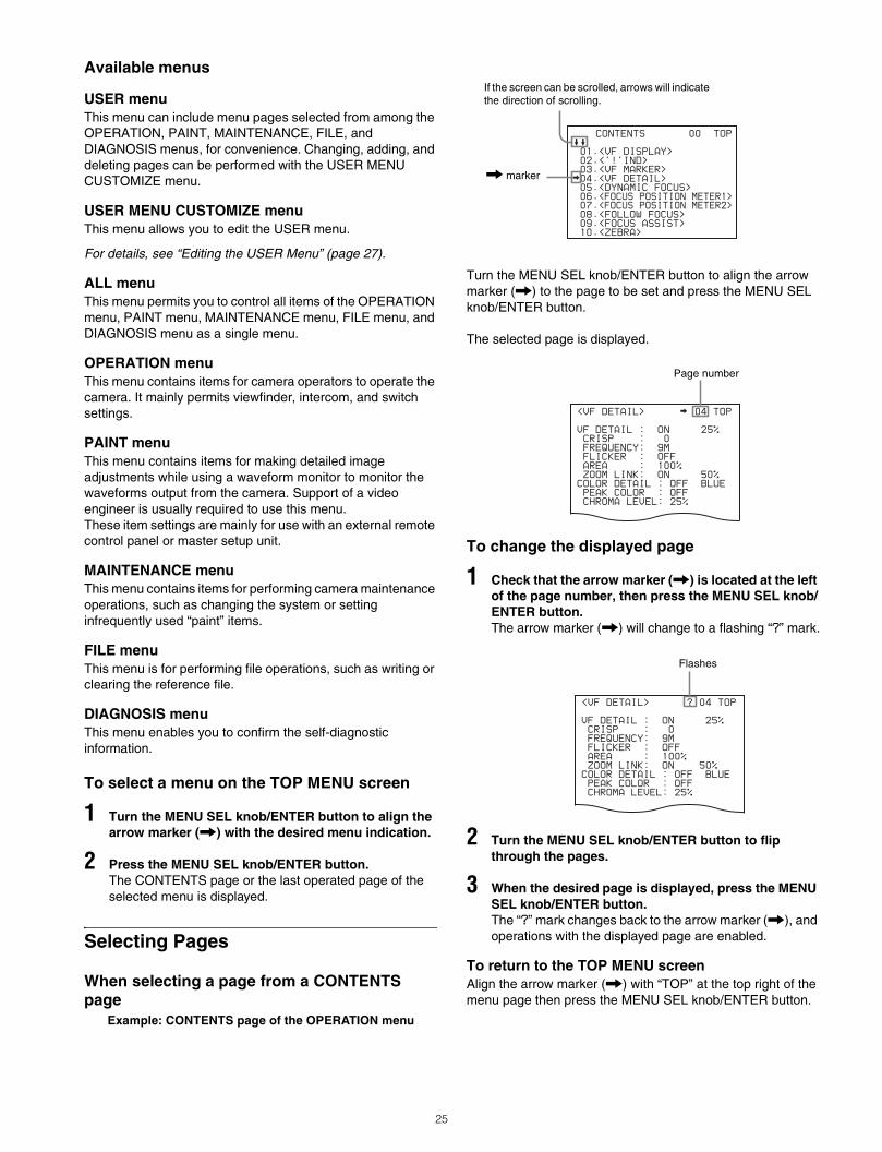
When selecting a page from a CONTENTS page
Example: CONTENTS page of the OPERATION menu
Turn the MENU SEL knob/ENTER button to align the arrow marker (,) to the page to be set and press the MENU SEL knob/ENTER button.
The selected page is displayed.
To change the displayed page
1 Check that the arrow marker (,) is located at the left of the page number, then press the MENU SEL knob/ENTER button.The arrow marker (,) will change to a flashing “?” mark.
2 Turn the MENU SEL knob/ENTER button to flip through the pages.
3 When the desired page is displayed, press the MENU SEL knob/ENTER button.The “?” mark changes back to the arrow marker (,), and operations with the displayed page are enabled.
To return to the TOP MENU screenAlign the arrow marker (,) with “TOP” at the top right of the menu page then press the MENU SEL knob/ENTER button.
CONTENTS 00 TOP
01.<VF DISPLAY>
02.<'!'IND>
03.<VF MARKER>
04.<VF DETAIL>
05.<DYNAMIC FOCUS>
06.<FOCUS POSITION METER1>
07.<FOCUS POSITION METER2>
08.<FOLLOW FOCUS>
09.<FOCUS ASSIST>
10.<ZEBRA>
If the screen can be scrolled, arrows will indicate the direction of scrolling.
, marker
<VF DETAIL> 04 TOP
VF DETAIL : ON 25%
CRISP : 0
FREQUENCY: 9M
FLICKER : OFF
AREA : 100%
ZOOM LINK: ON 50%
COLOR DETAIL : OFF BLUE
PEAK COLOR : OFF
CHROMA LEVEL: 25%
Page number
<VF DETAIL> ? 04 TOP
VF DETAIL : ON 25%
CRISP : 0
FREQUENCY: 9M
FLICKER : OFF
AREA : 100%
ZOOM LINK: ON 50%
COLOR DETAIL : OFF BLUE
PEAK COLOR : OFF
CHROMA LEVEL: 25%
Flashes
25
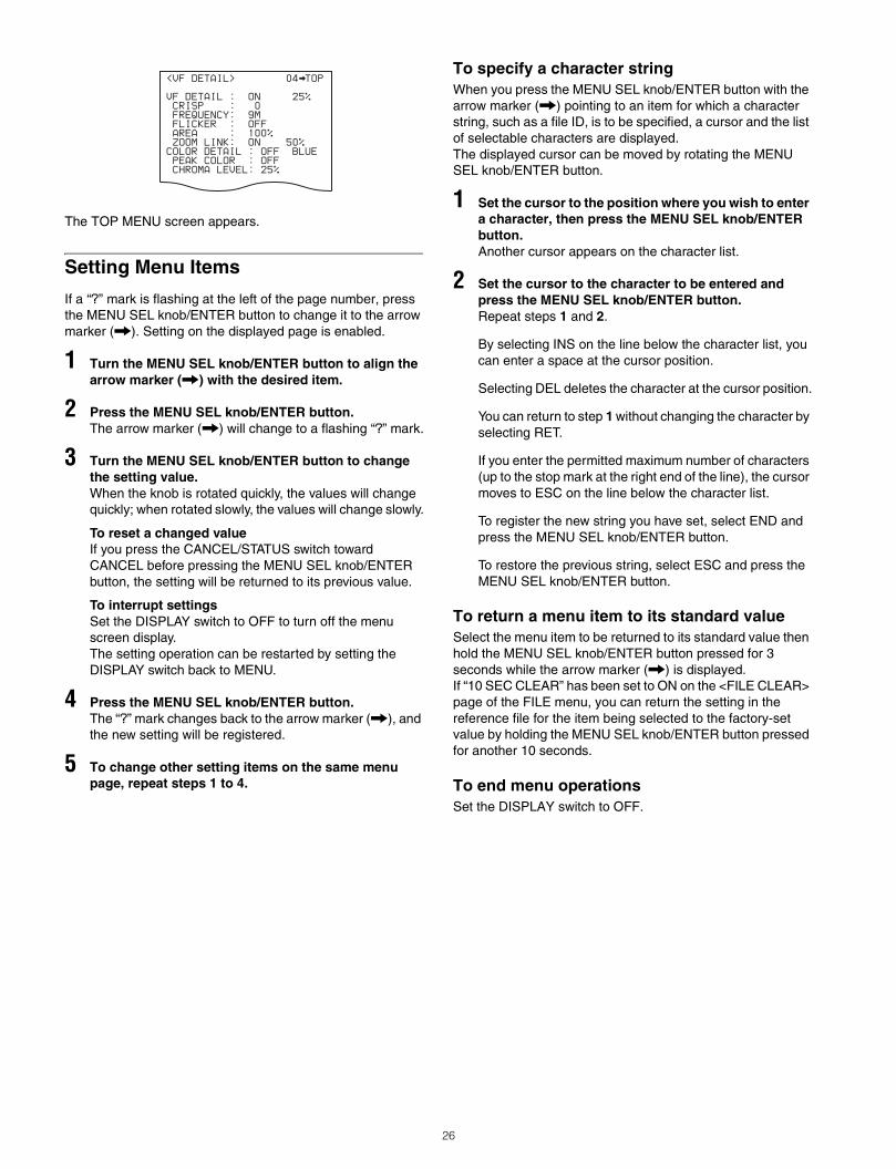
The TOP MENU screen appears.
Setting Menu Items
If a “?” mark is flashing at the left of the page number, press the MENU SEL knob/ENTER button to change it to the arrow marker (,). Setting on the displayed page is enabled.
1 Turn the MENU SEL knob/ENTER button to align the arrow marker (,) with the desired item.
2 Press the MENU SEL knob/ENTER button.The arrow marker (,) will change to a flashing “?” mark.
3 Turn the MENU SEL knob/ENTER button to change the setting value.When the knob is rotated quickly, the values will change quickly; when rotated slowly, the values will change slowly.
To reset a changed valueIf you press the CANCEL/STATUS switch toward CANCEL before pressing the MENU SEL knob/ENTER button, the setting will be returned to its previous value.
To interrupt settingsSet the DISPLAY switch to OFF to turn off the menu screen display.The setting operation can be restarted by setting the DISPLAY switch back to MENU.
4 Press the MENU SEL knob/ENTER button.The “?” mark changes back to the arrow marker (,), and the new setting will be registered.
5 To change other setting items on the same menu page, repeat steps 1 to 4.
To specify a character stringWhen you press the MENU SEL knob/ENTER button with the arrow marker (,) pointing to an item for which a character string, such as a file ID, is to be specified, a cursor and the list of selectable characters are displayed.The displayed cursor can be moved by rotating the MENU SEL knob/ENTER button.
1 Set the cursor to the position where you wish to enter a character, then press the MENU SEL knob/ENTER button.Another cursor appears on the character list.
2 Set the cursor to the character to be entered and press the MENU SEL knob/ENTER button.Repeat steps 1 and 2.
By selecting INS on the line below the character list, you can enter a space at the cursor position.
Selecting DEL deletes the character at the cursor position.
You can return to step 1 without changing the character by selecting RET.
If you enter the permitted maximum number of characters (up to the stop mark at the right end of the line), the cursor moves to ESC on the line below the character list.
To register the new string you have set, select END and press the MENU SEL knob/ENTER button.
To restore the previous string, select ESC and press the MENU SEL knob/ENTER button.
To return a menu item to its standard valueSelect the menu item to be returned to its standard value then hold the MENU SEL knob/ENTER button pressed for 3 seconds while the arrow marker (,) is displayed.If “10 SEC CLEAR” has been set to ON on the <FILE CLEAR> page of the FILE menu, you can return the setting in the reference file for the item being selected to the factory-set value by holding the MENU SEL knob/ENTER button pressed for another 10 seconds.
To end menu operationsSet the DISPLAY switch to OFF.
<VF DETAIL> 04 TOP
VF DETAIL : ON 25%
CRISP : 0
FREQUENCY: 9M
FLICKER : OFF
AREA : 100%
ZOOM LINK: ON 50%
COLOR DETAIL : OFF BLUE
PEAK COLOR : OFF
CHROMA LEVEL: 25%
26
Editing the USER Menu
You can select desired pages and items from the OPERATION, PAINT, MAINTENANCE, FILE, and DIAGNOSIS menus and register them to the USER menu.If you specify pages or items frequently used for the USER menu, you can easily call and use them.
The following pages are included on the factory-set USER menu:
For the items on each page, see the corresponding source menu page in the table in “Menu List” (page 30).
The USER MENU CUSTOMIZE menu allows you to configure a USER menu that consists only of pages and items that you need, by your adding, deleting or replacing pages.
Editing by itemsThe USER MENU CUSTOMIZE menu allows you to add a new page to the USER menu and add desired items to the page.While the EDIT page contains factory-preset items, the USER 1 EDIT to USER 19 EDIT pages are all blank in their initial state. You can register up to 10 items, including blank lines, on each of these pages.
To add items to a pageProceed as follows.
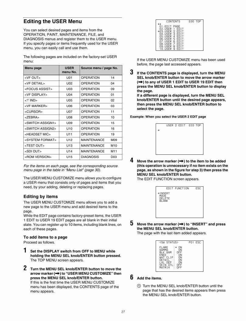
1 Set the DISPLAY switch from OFF to MENU while holding the MENU SEL knob/ENTER button pressed.The TOP MENU screen appears.
2 Turn the MENU SEL knob/ENTER button to move the arrow marker (,) to “USER MENU CUSTOMIZE” then press the MENU SEL knob/ENTER button.If this is the first time the USER MENU CUSTOMIZE menu has been displayed, the CONTENTS page of the menu appears.
If the USER MENU CUSTOMIZE menu has been used before, the page last accessed appears.
3 If the CONTENTS page is displayed, turn the MENU SEL knob/ENTER button to move the arrow marker (,) to any of USER 1 EDIT to USER 19 EDIT then press the MENU SEL knob/ENTER button to display the page.If a different page is displayed, turn the MENU SEL knob/ENTER button until the desired page appears, then press the MENU SEL knob/ENTER button to select the page.
Example: When you select the USER 2 EDIT page
4 Move the arrow marker (,) to the item to be added (this operation is unnecessary if no item exists on the page, as shown in the figure for step 3) then press the MENU SEL knob/ENTER button.The EDIT FUNCTION screen appears.
5 Move the arrow marker (,) to “INSERT” and press the MENU SEL knob/ENTER button.The page with the last item added appears.
6 Add the items.
1 Turn the MENU SEL knob/ENTER button until the page that has the desired items appears then press the MENU SEL knob/ENTER button.
Menu page USERmenu No.
Source menu / page No.
<VF OUT> U01 OPERATION 14
<VF DETAIL> U02 OPERATION 04
<FOCUS ASSIST> U03 OPERATION 09
<VF DISPLAY> U04 OPERATION 01
<‘!’ IND> U05 OPERATION 02
<VF MARKER> U06 OPERATION 03
<CURSOR> U07 OPERATION 11
<ZEBRA> U08 OPERATION 10
<SWITCH ASSIGN1> U09 OPERATION 15
<SWITCH ASSIGN2> U10 OPERATION 16
<HEADSET MIC> U11 OPERATION 19
<SYSTEM FORMAT> U12 MAINTENANCE M09
<TEST OUT> U13 MAINTENANCE M10
<SDI OUT> U14 MAINTENANCE M11
<ROM VERSION> U15 DIAGNOSIS D03
CONTENTS E00
xx
01.EDIT PAGE
02.USER 1 EDITc03.USER 2 EDIT
04.USER 3 EDIT
05.USER 4 EDIT
06.USER 5 EDIT
07.USER 6 EDIT
08.USER 7 EDIT
09.USER 8 EDIT
10.USER 9 EDIT
TOP
USER 2 EDIT E03
c
TOP
EDIT FUNCTION
cINSERT
MOVE
DELETE
BLANK
ESC
<SW STATUS> P01
FLARE :c ON
GAMMA : ON
BLK GAM : OFF
KNEE : ON
WHT CLIP: ON
DETAIL : ON
LVL DEP : ON
SKIN DTL: OFF
MATRIX : OFF
ESC
27
2 Turn the MENU SEL knob/ENTER button to move the arrow marker (,) to the desired item then press the MENU SEL knob/ENTER button.
The USER 2 EDIT page appears again, displaying the newly added item.
7 Add the remaining items by repeating steps 4 to 6.You can add up to 10 items on one page.
To delete items from a pageProceed as follows.
1 Move the arrow marker (,) to the item to be deleted, and press the MENU SEL knob/ENTER button.The EDIT FUNCTION screen appears.
2 Select DELETE then press the MENU SEL knob/ENTER button.The previously displayed page appears again, and the message “DELETE OK? YES,NO” appears at the upper right.
3 To delete, turn the MENU SEL knob/ENTER button to move the arrow marker (,) to “YES,” and press the MENU SEL knob/ENTER button.
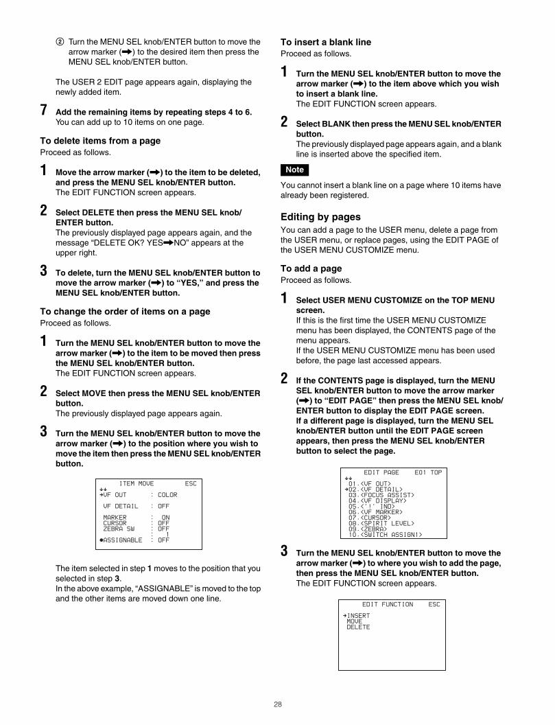
To change the order of items on a pageProceed as follows.
1 Turn the MENU SEL knob/ENTER button to move the arrow marker (,) to the item to be moved then press the MENU SEL knob/ENTER button.The EDIT FUNCTION screen appears.
2 Select MOVE then press the MENU SEL knob/ENTER button.The previously displayed page appears again.
3 Turn the MENU SEL knob/ENTER button to move the arrow marker (,) to the position where you wish to move the item then press the MENU SEL knob/ENTER button.
The item selected in step 1 moves to the position that you selected in step 3.In the above example, “ASSIGNABLE” is moved to the top and the other items are moved down one line.
To insert a blank lineProceed as follows.
1 Turn the MENU SEL knob/ENTER button to move the arrow marker (,) to the item above which you wish to insert a blank line.The EDIT FUNCTION screen appears.
2 Select BLANK then press the MENU SEL knob/ENTER button.The previously displayed page appears again, and a blank line is inserted above the specified item.
You cannot insert a blank line on a page where 10 items have already been registered.
Editing by pagesYou can add a page to the USER menu, delete a page from the USER menu, or replace pages, using the EDIT PAGE of the USER MENU CUSTOMIZE menu.
To add a pageProceed as follows.
1 Select USER MENU CUSTOMIZE on the TOP MENU screen.If this is the first time the USER MENU CUSTOMIZE menu has been displayed, the CONTENTS page of the menu appears.If the USER MENU CUSTOMIZE menu has been used before, the page last accessed appears.
2 If the CONTENTS page is displayed, turn the MENU SEL knob/ENTER button to move the arrow marker (,) to “EDIT PAGE” then press the MENU SEL knob/ENTER button to display the EDIT PAGE screen.If a different page is displayed, turn the MENU SEL knob/ENTER button until the EDIT PAGE screen appears, then press the MENU SEL knob/ENTER button to select the page.
3 Turn the MENU SEL knob/ENTER button to move the arrow marker (,) to where you wish to add the page, then press the MENU SEL knob/ENTER button.The EDIT FUNCTION screen appears.
ITEM MOVE
xx
cVF OUT : COLOR
VF DETAIL : OFF
MARKER : ON
CURSOR : OFF
ZEBRA SW : OFF
: 1zASSIGNABLE : OFF
ESC
Note
EDIT PAGE E01
xx
01.<VF OUT>c02.<VF DETAIL>
03.<FOCUS ASSIST>
04.<VF DISPLAY>
05.<'!' IND>
06.<VF MARKER>
07.<CURSOR>
08.<SPIRIT LEVEL>
09.<ZEBRA>
10.<SWITCH ASSIGN1>
TOP
EDIT FUNCTION
cINSERT
MOVE
DELETE
ESC
28
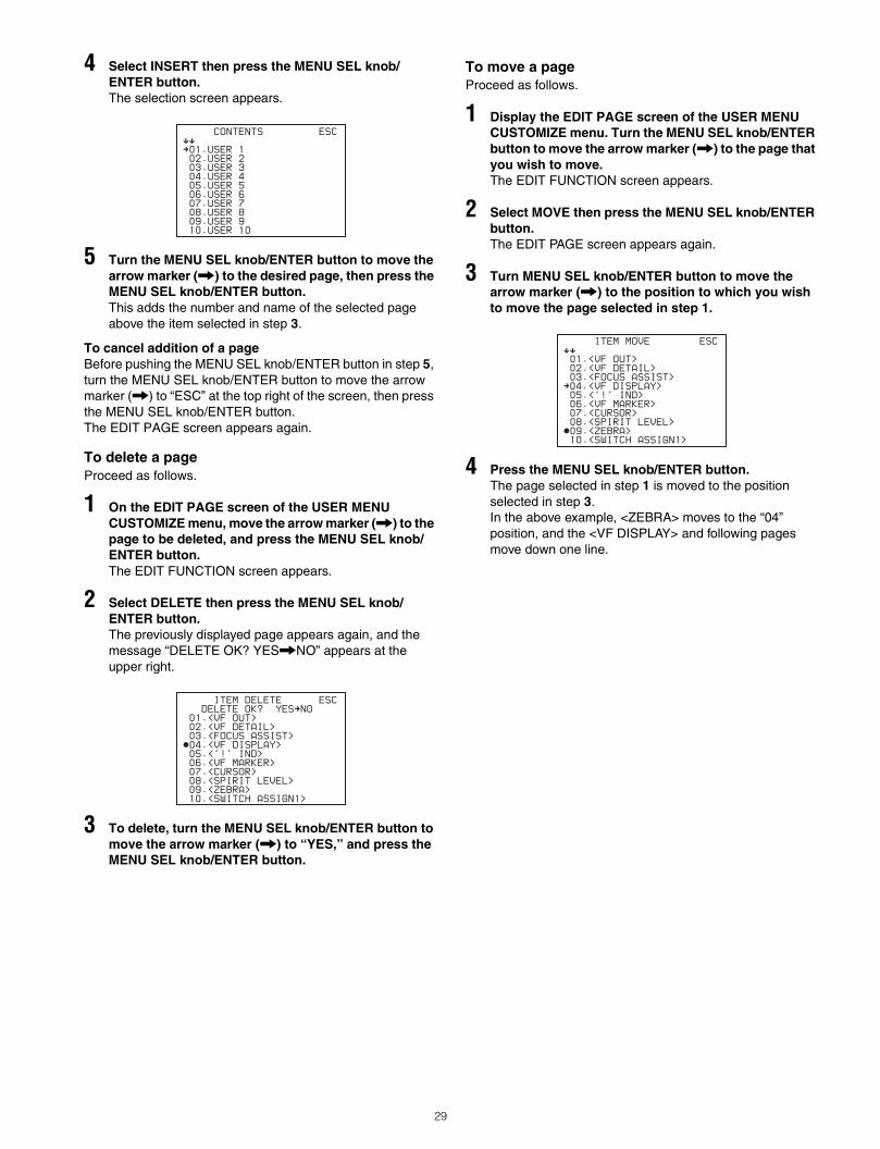
4 Select INSERT then press the MENU SEL knob/ENTER button.The selection screen appears.
5 Turn the MENU SEL knob/ENTER button to move the arrow marker (,) to the desired page, then press the MENU SEL knob/ENTER button.This adds the number and name of the selected page above the item selected in step 3.
To cancel addition of a pageBefore pushing the MENU SEL knob/ENTER button in step 5, turn the MENU SEL knob/ENTER button to move the arrow marker (,) to “ESC” at the top right of the screen, then press the MENU SEL knob/ENTER button.The EDIT PAGE screen appears again.
To delete a pageProceed as follows.
1 On the EDIT PAGE screen of the USER MENU CUSTOMIZE menu, move the arrow marker (,) to the page to be deleted, and press the MENU SEL knob/ENTER button.The EDIT FUNCTION screen appears.
2 Select DELETE then press the MENU SEL knob/ENTER button.The previously displayed page appears again, and the message “DELETE OK? YES,NO” appears at the upper right.
3 To delete, turn the MENU SEL knob/ENTER button to move the arrow marker (,) to “YES,” and press the MENU SEL knob/ENTER button.
To move a pageProceed as follows.
1 Display the EDIT PAGE screen of the USER MENU CUSTOMIZE menu. Turn the MENU SEL knob/ENTER button to move the arrow marker (,) to the page that you wish to move.The EDIT FUNCTION screen appears.
2 Select MOVE then press the MENU SEL knob/ENTER button.The EDIT PAGE screen appears again.
3 Turn MENU SEL knob/ENTER button to move the arrow marker (,) to the position to which you wish to move the page selected in step 1.
4 Press the MENU SEL knob/ENTER button.The page selected in step 1 is moved to the position selected in step 3.In the above example, <ZEBRA> moves to the “04” position, and the <VF DISPLAY> and following pages move down one line.
CONTENTS
xx
c01.USER 1
02.USER 2
03.USER 3
04.USER 4
05.USER 5
06.USER 6
07.USER 7
08.USER 8
09.USER 9
10.USER 10
ESC
ITEM DELETE
DELETE OK? YEScNO
01.<VF OUT>
02.<VF DETAIL>
03.<FOCUS ASSIST>z04.<VF DISPLAY>
05.<'!' IND>
06.<VF MARKER>
07.<CURSOR>
08.<SPIRIT LEVEL>
09.<ZEBRA>
10.<SWITCH ASSIGN1>
ESC
ITEM MOVE
xx
01.<VF OUT>
02.<VF DETAIL>
03.<FOCUS ASSIST>c04.<VF DISPLAY>
05.<'!' IND>
06.<VF MARKER>
07.<CURSOR>
08.<SPIRIT LEVEL>z09.<ZEBRA>
10.<SWITCH ASSIGN1>
ESC
29
Menu List
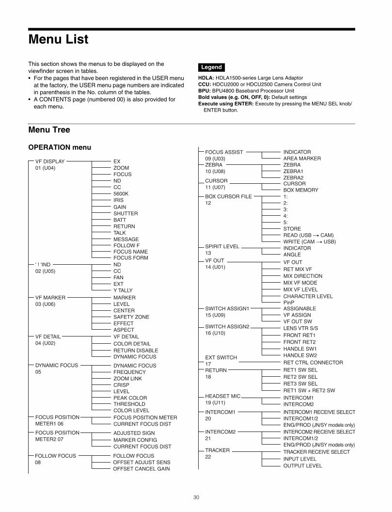
This section shows the menus to be displayed on the viewfinder screen in tables.• For the pages that have been registered in the USER menu
at the factory, the USER menu page numbers are indicated in parenthesis in the No. column of the tables.
• A CONTENTS page (numbered 00) is also provided for each menu.
HDLA: HDLA1500-series Large Lens AdaptorCCU: HDCU2000 or HDCU2500 Camera Control UnitBPU: BPU4800 Baseband Processor UnitBold values (e.g. ON, OFF, 0): Default settingsExecute using ENTER: Execute by pressing the MENU SEL knob/
ENTER button.
Menu Tree
OPERATION menu
Legend
VF DISPLAY01 (U04)
' ! 'IND02 (U05)
VF MARKER03 (U06)
VF DE
DYNAMIC FOCUS05
TAIL04 (U02)
EXZOOMFOCUSNDCC5600KIRISGAINSHUTTERBATTRETURNTALKMESSFOLLOW FFOCUS NAMEFOCUS FORM
AGE
NDCCFANEXTY TALLYMARKERLEVELCENTERSAFETY ZONEEFFECTASPECT
DYNAMIC FOCUSFREQUENCY
FOCUS POSITION METER1 06
FOCUS POSITION METERCURRENT FOCUS DIST
FOCUS POSITION METER2 07
ADJUSTED SIGNMARKER CONFIGCURRENT FOCUS DIST
ZOOM LINKCRISPLEVELPEAK COLORTHRESHOLDCOLOR LEVEL
VF DETAILCOLOR DERETURN DISABLEDYNAMIC FOCUS
TAIL
FOLLOW FOCUS08
FOLLOW FOCUSOFFSET ADJUST SENSOFFSET CANCEL GAIN
FOCUS ASSIST09 (U03)
RET MIX VFMIX DIRECTIONMIX VF MODEMIX VF LEVELCHARACTER LEVEL
ZEBRA10 (U08)
ZEBRAZEBRA1ZEBRA2
SWITCH ASSIGN115 (U09)
ASSIGNABLEVF ASSIGNVF OUT SW
INDICATORAREA MARKER
CURSOR11 (U07)
CURSORBOX MEMORY1:2:3:4:5:STOREREAD (USB t CAM)WRITE (CAM t USB)
SPIRIT LEVEL13
BOX CURSOR FILE12
INDICATORANGLE
VF OUT14 (U01)
HEADSET MIC19 (U11)
INTERCOM1INTERCOM2
INTERCOM120
INTERCOM1 RECEIVE SELECTINTERCOM1/2ENG/PROD (JN/SY models only)
INTERCOM221
INTERCOM2 RECEIVE SELECTINTERCOM1/2ENG/PROD (JN/SY models only)
VF OUT
PinP
FRONT RET1FRONT RET2HANDLE SW1
SWITCH ASSIGN216 (U10)
LENS VTR S/S
RET2 SW SELRET3 SW SELRET1 SW + RET2 SW
RETURN18
RET1 SW SEL
INPUT LEVELOUTPUT LEVEL
TRACKER22
TRACKER RECEIVE SELECT
HANDLE SW2EXT SWITCH17 RET CTRL CONNECTOR
30
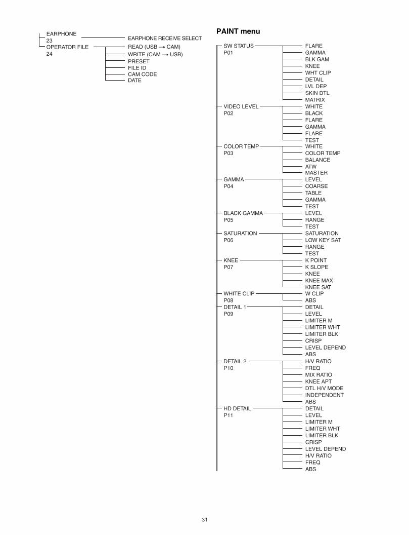
PAINT menu
WRITE (CAM t USB)PRESETFILE ID
OPERATOR FILE24
READ (USB t CAM)
CAM CODEDATE
EARPHONE23 EARPHONE RECEIVE SELECT
SW STATUSP01
VIDEO LEVELP02
COLOR TEMPP03
GAMMAP04
BLACK GAMMAP05
SATURATIONP06
KNEEP07
WHITE CLIPP08DETAIL 1P09
FLAREGAMMABLK GAMKNEEWHT CLIPDETAILLVL DEPSKIN DTLMATRIXWHITEBLACKFLAREGAMMAFLARETESTWHITE
ATW
COLOR TEMPBALANCE
MASTERLEVELCOARSETABLEGAMMATESTLEVELRANGETESTSATURATIONLOW KEY SATRANGETESTK POINTK SLOPEKNEEKNEE MAXKNEE SATW CLIPABSDETAILLEVELLIMITER MLIMITER WHTLIMITER BLKCRISPLEVEL DEPENDABS
DETAIL 2P10
H/V R
HD DETAIL DETAILP11 LEVEL LIMITER M LIMITER WHT LIMITER BLK CRISP LEVEL DEPEND H/V RATIO FREQ ABS
ATIOFREQMIX RATIOKNEE APTDTL H/V MODEINDEPENDENTABS
31
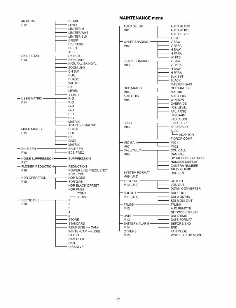
MAINTENANCE menu
DISSOLVE
SKIN DE
4K DETAILP12
TAILP13
USER MATRIXP14
MULTI MATRIXP15
SHUTTERP16
SKIN DTL
DETAILLEVELLIMITER MLIMITER WHTLIMITER BLKCRISPH/V RATIOFREQABS
SKIN GATENATURAL SKINDTLZOOM LINKCH SWHUEPHASEWIDTHSLEVEL
AT
Y LIMITR-GR-BG-RG-BB-RB-GMATRIXADAPTIVE MATRIXPHASEHUESATGATEMATRIXSHUTTERECS FREQ
NOISE SUPPRESSIONP17
SCENE FILEP20
FLICKER REDUCTIONP18 P
ACM TYPEOWER LINE FREQUENCY
REDUCTION
SUPPRESSION
12345STORESTANDARDREAD (USB t CAM)WRITE (CAM t USB)FILE IDCAM CODEDATE
HDR OPERATIONP19
HDR MODESDR GAINHDR BLACK OFFSETHDR KNEE POINT SLOPE
AUTO SETUPM01
WHITE SHADINGM02
BLACK SHADINGM03
OHB MATRIXM04AUTO IRISM05
LENSM06
MIC GAINM07 CALL/TALLYM08
SYSTEM FORMATM09 (U12)
AUTO BLACKAUTO WHITEAUTO LEVELTESTV SAWV PARAH SAWH PARAWHITEV SAWV PARAH SAWH PARABLK SETBLACKMASTER GAINOHB MATRIXMATRIXAUTO IRISWINDOWOVERRIDEIRIS LEVELAPL RATIOIRIS GAINIRIS CLOSEF NAF DISPLAY
O. DISP
ALAC ADAPTORF DROP COMPMIC1MIC2CCU CALLCAM CALLUP TALLY BRIGHTNESS
CAMERA NUMBERNUMBER DISPLAY
TALLY GUARDCURRENT
TEST OUTM10 (U13)
OUTPUTVBS-OUTDOWN CONVERTER
SDI OUTM11 (U14)
TRUNKM12
DATEM13BATTERY ALARMM14OTHERSM15
SDI-1 OUTSDI-2 OUT/INSDI-MONI OUTTRUNKAUX REMOTENETWORK TRUNKDATE/TIMEDATE FORMATBEFORE ENDENDFAN MODEWHITE SETUP MODE
32
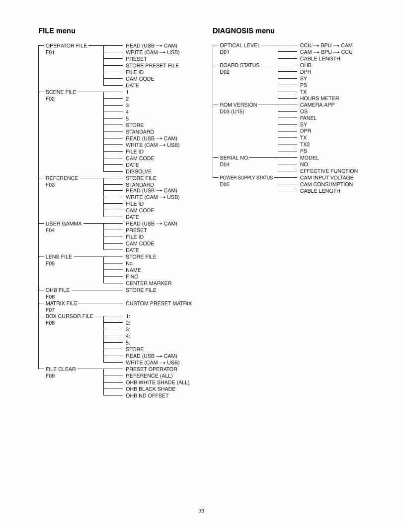
FILE menu DIAGNOSIS menu
OPERATOR FILEF01
SCENE FILEF02
REFERENCEF03
USER GAMMAF04
LENS FILEF05
OHB FILEF06
FILE CLEARF09
READ (USB t CAM)WRITE (CAM t USB)PRESETSTORE PRESET FILEFILE IDCAM CODEDATE12345STORESTANDARDREAD (USB t CAM)WRITE (CAM t USB)FILE IDCAM CODEDDISSOLVE
ATE
STORE FILESTANDARDREAD (USB t CAM)WRITE (CAM t USB)FILE IDCAM CODEDATEREAD (USB t CAM)PRESETFILE IDCAM CODEDATESTORE FILENo.NAMEF NOCENTER MARKERSTORE FILE
PRESET OPER
BOX CURSOR FILEF08
1:2:3:4:5:STOREREAD (USB t CAM)WRITE (CAM t USB)
ATORREFERENCE (ALL)OHB WHITE SHADE (ALL)OHB BLACK SHADEOHB ND OFFSET
MATRIX FILEF07
CUSTOM PRESET MATRIX
EFFECTIVE FUNCTIONCAM INPUT VOLTAGECAM CONSUMPTIONCABLE LENGTH
OPTICAL LEVELD01
BOARD STATUSD02
ROM VERSIOND03 (U15)
SERIAL NO.D04
POWER SUPPLY STATUSD05
CCU t BPU t CAMCAM t BPU t CCU
OHBDPR
DPR
SYPSTXHOURS METERCAMERA APPOSPANELSY
TXTX2PSMODELNO.
CABLE LENGTH
33
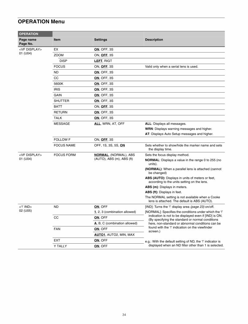
OPERATION Menu
OPERATION
Page namePage No.
Item Settings Description
<VF DISPLAY>01 (U04)
EX ON, OFF, 3S
ZOOM ON, OFF, 3S
DISP LEFT, RIGT
FOCUS ON, OFF, 3S Valid only when a serial lens is used.
ND ON, OFF, 3S
CC ON, OFF, 3S
5600K ON, OFF, 3S
IRIS ON, OFF, 3S
GAIN ON, OFF, 3S
SHUTTER ON, OFF, 3S
BATT ON, OFF, 3S
RETURN ON, OFF, 3S
TALK ON, OFF, 3S
MESSAGE ALL, WRN, AT, OFF ALL: Displays all messages.
WRN: Displays warning messages and higher.
AT: Displays Auto Setup messages and higher.
FOLLOW F ON, OFF, 3S
FOCUS NAME OFF, 1S, 3S, 5S, ON Sets whether to show/hide the marker name and sets the display time.
<VF DISPLAY>01 (U04)
FOCUS FORM NORMAL, (NORMAL), ABS (AUTO), ABS (m), ABS (ft)
Sets the focus display method.
NORMAL: Displays a value in the range 0 to 255 (no units).
(NORMAL): When a parallel lens is attached (cannot be changed)
ABS (AUTO): Displays in units of meters or feet, according to the units setting on the lens.
ABS (m): Displays in meters.
ABS (ft): Displays in feet.
The NORMAL setting is not available when a Cooke lens is attached. The default is ABS (AUTO).
<‘!’ IND>02 (U05)
ND ON, OFF
1, 2, 3 (combination allowed)
[IND]: Turns the ‘!’ display area (page 23) on/off.
[NORMAL]: Specifies the conditions under which the ‘!’ indication is not to be displayed even if [IND] is ON. (By specifying the standard or normal conditions here, non-standard or abnormal conditions can be found with the ‘!’ indication on the viewfinder screen.)
e.g.: With the default setting of ND, the ‘!’ indicator is displayed when an ND filter other than 1 is selected.
CC ON, OFF
A, B, C (combination allowed)
FAN ON, OFF
AUTO1, AUTO2, MIN, MAX
EXT ON, OFF
Y TALLY ON, OFF
34
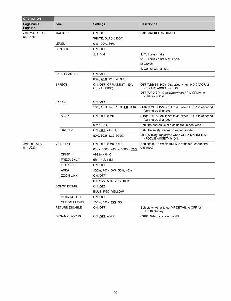
<VF MARKER>03 (U06)
MARKER ON, OFF Sets MARKER to ON/OFF.
WHITE, BLACK, DOT
LEVEL 0 to 100%, 40%
CENTER ON, OFF
1, 2, 3, 4 1: Full cross hairs
2: Full cross hairs with a hole
3: Center
4: Center with a hole
SAFETY ZONE ON, OFF
80.0, 90.0, 92.5, 95.0%
EFFECT ON, OFF, OFF(ASSIST IND), OFF(AF DISP)
OFF(ASSIST IND): Displayed when INDICATOR of <FOCUS ASSIST> is ON.
OFF(AF DISP): Displayed when AF DISPLAY of <LENS> is ON.
ASPECT ON, OFF
16:9, 15:9, 14:9, 13:9, 4:3, (4.3) (4.3): If VF SCAN is set to 4:3 when HDLA is attached (cannot be changed)
MASK ON, OFF, (ON) (ON): If VF SCAN is set to 4:3 when HDLA is attached (cannot be changed)
0 to 15, 12 Sets the darken level outside the aspect area.
SAFETY ON, OFF, (AREA) Sets the safety marker in Aspect mode.
OFF(AREA): Displayed when AREA MARKER of <FOCUS ASSIST> is ON.
80.0, 90.0, 92.5, 95.0%
<VF DETAIL>04 (U02)
VF DETAIL ON, OFF, (ON), (OFF) Settings in ( ): When HDLA is attached (cannot be changed)0% to 100%, (0% to 100%), 25%
CRISP –99 to +99, 0
FREQUENCY 9M, 14M, 18M
FLICKER ON, OFF
AREA 100%, 70%, 60%, 50%, 40%
ZOOM LINK ON, OFF
0%, 25%, 50%, 75%, 100%
COLOR DETAIL ON, OFF
BLUE, RED, YELLOW
PEAK COLOR ON, OFF
CHROMA LEVEL 100%, 50%, 25%, 0%
RETURN DISABLE ON, OFF Selects whether to set VF DETAIL to OFF for RETURN display.
DYNAMIC FOCUS ON, OFF, (OFF) (OFF): When shooting in HD
OPERATION
Page namePage No.
Item Settings Description
35
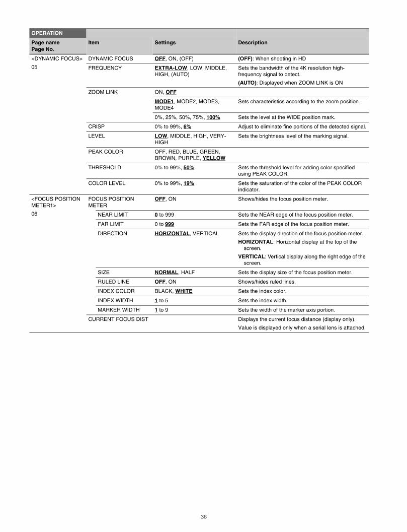
<DYNAMIC FOCUS>
05
DYNAMIC FOCUS OFF, ON, (OFF) (OFF): When shooting in HD
FREQUENCY EXTRA-LOW, LOW, MIDDLE, HIGH, (AUTO)
Sets the bandwidth of the 4K resolution high-frequency signal to detect.
(AUTO): Displayed when ZOOM LINK is ON
ZOOM LINK ON, OFF
MODE1, MODE2, MODE3, MODE4
Sets characteristics according to the zoom position.
0%, 25%, 50%, 75%, 100% Sets the level at the WIDE position mark.
CRISP 0% to 99%, 6% Adjust to eliminate fine portions of the detected signal.
LEVEL LOW, MIDDLE, HIGH, VERY-HIGH
Sets the brightness level of the marking signal.
PEAK COLOR OFF, RED, BLUE, GREEN, BROWN, PURPLE, YELLOW
THRESHOLD 0% to 99%, 50% Sets the threshold level for adding color specified using PEAK COLOR.
COLOR LEVEL 0% to 99%, 19% Sets the saturation of the color of the PEAK COLOR indicator.
<FOCUS POSITION METER1>
06
FOCUS POSITION METER
OFF, ON Shows/hides the focus position meter.
NEAR LIMIT 0 to 999 Sets the NEAR edge of the focus position meter.
FAR LIMIT 0 to 999 Sets the FAR edge of the focus position meter.
DIRECTION HORIZONTAL, VERTICAL Sets the display direction of the focus position meter.
HORIZONTAL: Horizontal display at the top of the screen.
VERTICAL: Vertical display along the right edge of the screen.
SIZE NORMAL, HALF Sets the display size of the focus position meter.
RULED LINE OFF, ON Shows/hides ruled lines.
INDEX COLOR BLACK, WHITE Sets the index color.
INDEX WIDTH 1 to 5 Sets the index width.
MARKER WIDTH 1 to 9 Sets the width of the marker axis portion.
CURRENT FOCUS DIST Displays the current focus distance (display only).
Value is displayed only when a serial lens is attached.
OPERATION
Page namePage No.
Item Settings Description
36
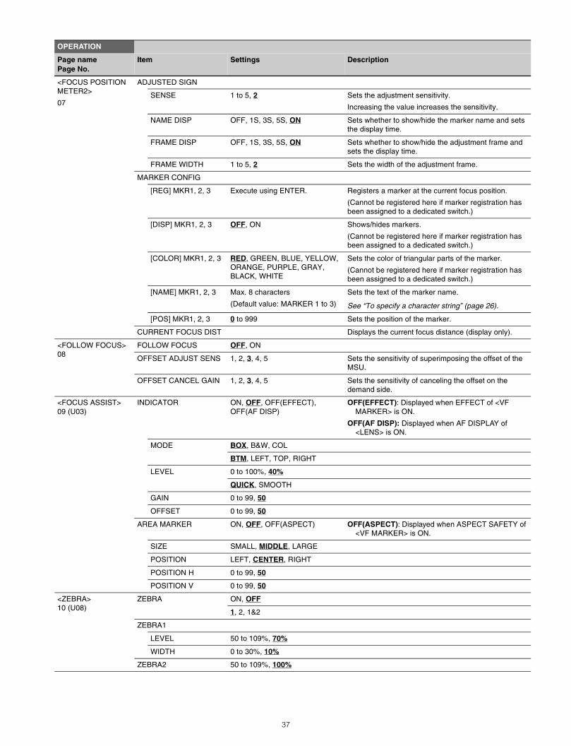
<FOCUS POSITION METER2>
07
ADJUSTED SIGN
SENSE 1 to 5, 2 Sets the adjustment sensitivity.
Increasing the value increases the sensitivity.
NAME DISP OFF, 1S, 3S, 5S, ON Sets whether to show/hide the marker name and sets the display time.
FRAME DISP OFF, 1S, 3S, 5S, ON Sets whether to show/hide the adjustment frame and sets the display time.
FRAME WIDTH 1 to 5, 2 Sets the width of the adjustment frame.
MARKER CONFIG
[REG] MKR1, 2, 3 Execute using ENTER. Registers a marker at the current focus position.
(Cannot be registered here if marker registration has been assigned to a dedicated switch.)
[DISP] MKR1, 2, 3 OFF, ON Shows/hides markers.
(Cannot be registered here if marker registration has been assigned to a dedicated switch.)
[COLOR] MKR1, 2, 3 RED, GREEN, BLUE, YELLOW, ORANGE, PURPLE, GRAY, BLACK, WHITE
Sets the color of triangular parts of the marker.
(Cannot be registered here if marker registration has been assigned to a dedicated switch.)
[NAME] MKR1, 2, 3 Max. 8 characters
(Default value: MARKER 1 to 3)
Sets the text of the marker name.
See “To specify a character string” (page 26).
[POS] MKR1, 2, 3 0 to 999 Sets the position of the marker.
CURRENT FOCUS DIST Displays the current focus distance (display only).
<FOLLOW FOCUS>08
FOLLOW FOCUS OFF, ON
OFFSET ADJUST SENS 1, 2, 3, 4, 5 Sets the sensitivity of superimposing the offset of the MSU.
OFFSET CANCEL GAIN 1, 2, 3, 4, 5 Sets the sensitivity of canceling the offset on the demand side.
<FOCUS ASSIST>09 (U03)
INDICATOR ON, OFF, OFF(EFFECT), OFF(AF DISP)
OFF(EFFECT): Displayed when EFFECT of <VF MARKER> is ON.
OFF(AF DISP): Displayed when AF DISPLAY of <LENS> is ON.
MODE BOX, B&W, COL
BTM, LEFT, TOP, RIGHT
LEVEL 0 to 100%, 40%
QUICK, SMOOTH
GAIN 0 to 99, 50
OFFSET 0 to 99, 50
AREA MARKER ON, OFF, OFF(ASPECT) OFF(ASPECT): Displayed when ASPECT SAFETY of <VF MARKER> is ON.
SIZE SMALL, MIDDLE, LARGE
POSITION LEFT, CENTER, RIGHT
POSITION H 0 to 99, 50
POSITION V 0 to 99, 50
<ZEBRA>10 (U08)
ZEBRA ON, OFF
1, 2, 1&2
ZEBRA1
LEVEL 50 to 109%, 70%
WIDTH 0 to 30%, 10%
ZEBRA2 50 to 109%, 100%
OPERATION
Page namePage No.
Item Settings Description
37
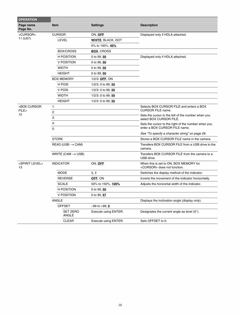
<CURSOR>11 (U07)
CURSOR ON, OFF Displayed only if HDLA attached.
LEVEL WHITE, BLACK, DOT
0% to 100%, 40%
BOX/CROSS BOX, CROSS
H POSITION 0 to 99, 50 Displayed only if HDLA attached.
V POSITION 0 to 99, 50
WIDTH 0 to 99, 50
HEIGHT 0 to 99, 50
BOX MEMORY 1/2/3: OFF, ON
H POSI 1/2/3: 0 to 99, 50
V POSI 1/2/3: 0 to 99, 50
WIDTH 1/2/3: 0 to 99, 50
HEIGHT 1/2/3: 0 to 99, 50
<BOX CURSOR FILE>12
1: Selects BOX CURSOR FILE and enters a BOX CURSOR FILE name.
Sets the cursor to the left of the number when you select BOX CURSOR FILE.
Sets the cursor to the right of the number when you enter a BOX CURSOR FILE name.
See “To specify a character string” on page 26.
2:
3:
4:
5:
STORE Stores a BOX CURSOR FILE name in the camera.
READ (USB t CAM) Transfers BOX CURSOR FILE from a USB drive to the camera.
WRITE (CAM t USB) Transfers BOX CURSOR FILE from the camera to a USB drive.
<SPIRIT LEVEL>13
INDICATOR ON, OFF When this is set to ON, BOX MEMORY for <CURSOR> does not function.
MODE 1, 2 Switches the display method of the indicator.
REVERSE OFF, ON Inverts the movement of the indicator horizontally.
SCALE 50% to 150%, 100% Adjusts the horizontal width of the indicator.
H POSITION 0 to 99, 50
V POSITION 0 to 99, 97
ANGLE Displays the inclination angle (display only).
OFFSET –99 to +99, 0
SET ZERO ANGLE
Execute using ENTER. Designates the current angle as level (0°).
CLEAR Execute using ENTER. Sets OFFSET to 0.
OPERATION
Page namePage No.
Item Settings Description
38
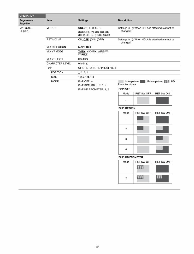
<VF OUT>14 (U01)
VF OUT COLOR, Y, R, G, B,
(COLOR), (Y), (R), (G), (B), (RET), (R+G), (R+B), (G+B)
Settings in ( ): When HDLA is attached (cannot be changed)
RET MIX VF ON, OFF, (ON), (OFF) Settings in ( ): When HDLA is attached (cannot be changed)
MIX DIRECTION MAIN, RET
MIX VF MODE Y-MIX, Y/C-MIX, WIRE(W), WIRE(B)
MIX VF LEVEL 0 to 99%
CHARACTER LEVEL 0 to 5, 4
PinP OFF, RETURN, HD PROMPTER
POSITION 1, 2, 3, 4
SIZE 1/2.5, 1/3, 1/4
MODE PinP OFF: ---
PinP RETURN: 1, 2, 3, 4
PinP HD PROMPTER: 1, 2
: Main picture, : Return picture, : HD Prompter picture
OPERATION
Page namePage No.
Item Settings Description
PinP: OFF
PinP: RETURN
PinP: HD PROMPTER
Mode RET SW OFF RET SW ON
---
Mode RET SW OFF RET SW ON
1
2
3
4
Mode RET SW OFF RET SW ON
1
2
39
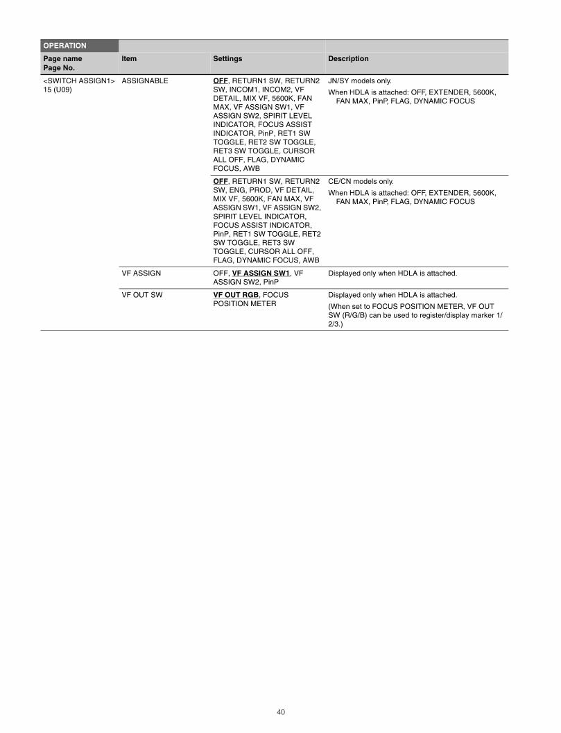
<SWITCH ASSIGN1>15 (U09)
ASSIGNABLE OFF, RETURN1 SW, RETURN2 SW, INCOM1, INCOM2, VF DETAIL, MIX VF, 5600K, FAN MAX, VF ASSIGN SW1, VF ASSIGN SW2, SPIRIT LEVEL INDICATOR, FOCUS ASSIST INDICATOR, PinP, RET1 SW TOGGLE, RET2 SW TOGGLE, RET3 SW TOGGLE, CURSOR ALL OFF, FLAG, DYNAMIC FOCUS, AWB
JN/SY models only.
When HDLA is attached: OFF, EXTENDER, 5600K, FAN MAX, PinP, FLAG, DYNAMIC FOCUS
OFF, RETURN1 SW, RETURN2 SW, ENG, PROD, VF DETAIL, MIX VF, 5600K, FAN MAX, VF ASSIGN SW1, VF ASSIGN SW2, SPIRIT LEVEL INDICATOR, FOCUS ASSIST INDICATOR, PinP, RET1 SW TOGGLE, RET2 SW TOGGLE, RET3 SW TOGGLE, CURSOR ALL OFF, FLAG, DYNAMIC FOCUS, AWB
CE/CN models only.
When HDLA is attached: OFF, EXTENDER, 5600K, FAN MAX, PinP, FLAG, DYNAMIC FOCUS
VF ASSIGN OFF, VF ASSIGN SW1, VF ASSIGN SW2, PinP
Displayed only when HDLA is attached.
VF OUT SW VF OUT RGB, FOCUS POSITION METER
Displayed only when HDLA is attached.
(When set to FOCUS POSITION METER, VF OUT SW (R/G/B) can be used to register/display marker 1/2/3.)
OPERATION
Page namePage No.
Item Settings Description
40
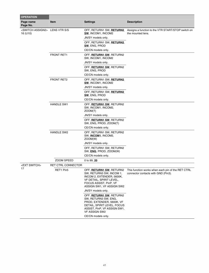
<SWITCH ASSIGN2>16 (U10)
LENS VTR S/S OFF, RETURN1 SW, RETURN2 SW, INCOM1, INCOM2
JN/SY models only.
Assigns a function to the VTR START/STOP switch on the mounted lens.
OFF, RETURN1 SW, RETURN2 SW, ENG, PROD
CE/CN models only.
FRONT RET1 OFF, RETURN1 SW, RETURN2 SW, INCOM1, INCOM2
JN/SY models only.
OFF, RETURN1 SW, RETURN2 SW, ENG, PROD
CE/CN models only.
FRONT RET2 OFF, RETURN1 SW, RETURN2 SW, INCOM1, INCOM2
JN/SY models only.
OFF, RETURN1 SW, RETURN2 SW, ENG, PROD
CE/CN models only.
HANDLE SW1 OFF, RETURN1 SW, RETURN2 SW, INCOM1, INCOM2, ZOOM(T)
JN/SY models only.
OFF, RETURN1 SW, RETURN2 SW, ENG, PROD, ZOOM(T)
CE/CN models only.
HANDLE SW2 OFF, RETURN1 SW, RETURN2 SW, INCOM1, INCOM2, ZOOM(W)
JN/SY models only.
OFF, RETURN1 SW, RETURN2 SW, ENG, PROD, ZOOM(W)
CE/CN models only.
ZOOM SPEED 0 to 99, 20
<EXT SWITCH>17
RET CTRL CONNECTOR
RET1 Pin5 OFF, RETURN1 SW, RETURN2 SW, RETURN3 SW, INCOM 1, INCOM 2, EXTENDER, 5600K, VF DETAIL, SPIRIT LEVEL, FOCUS ASSIST, PinP, VF ASSIGN SW1, VF ASSIGN SW2
JN/SY models only.
This function works when each pin of the RET CTRL connector contacts with GND (Pin3).
OFF, RETURN1 SW, RETURN2 SW, RETURN3 SW, ENG, PROD, EXTENDER, 5600K, VF DETAIL, SPIRIT LEVEL, FOCUS ASSIST, PinP, VF ASSIGN SW1, VF ASSIGN SW2
CE/CN models only.
OPERATION
Page namePage No.
Item Settings Description
41
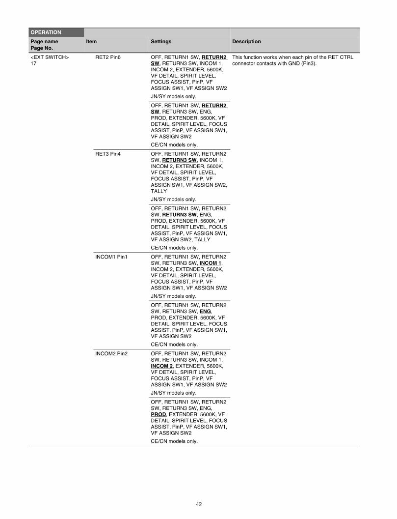
<EXT SWITCH>17
RET2 Pin6 OFF, RETURN1 SW, RETURN2 SW, RETURN3 SW, INCOM 1, INCOM 2, EXTENDER, 5600K, VF DETAIL, SPIRIT LEVEL, FOCUS ASSIST, PinP, VF ASSIGN SW1, VF ASSIGN SW2
JN/SY models only.
This function works when each pin of the RET CTRL connector contacts with GND (Pin3).
OFF, RETURN1 SW, RETURN2 SW, RETURN3 SW, ENG, PROD, EXTENDER, 5600K, VF DETAIL, SPIRIT LEVEL, FOCUS ASSIST, PinP, VF ASSIGN SW1, VF ASSIGN SW2
CE/CN models only.
RET3 Pin4 OFF, RETURN1 SW, RETURN2 SW, RETURN3 SW, INCOM 1, INCOM 2, EXTENDER, 5600K, VF DETAIL, SPIRIT LEVEL, FOCUS ASSIST, PinP, VF ASSIGN SW1, VF ASSIGN SW2, TALLY
JN/SY models only.
OFF, RETURN1 SW, RETURN2 SW, RETURN3 SW, ENG, PROD, EXTENDER, 5600K, VF DETAIL, SPIRIT LEVEL, FOCUS ASSIST, PinP, VF ASSIGN SW1, VF ASSIGN SW2, TALLY
CE/CN models only.
INCOM1 Pin1 OFF, RETURN1 SW, RETURN2 SW, RETURN3 SW, INCOM 1, INCOM 2, EXTENDER, 5600K, VF DETAIL, SPIRIT LEVEL, FOCUS ASSIST, PinP, VF ASSIGN SW1, VF ASSIGN SW2
JN/SY models only.
OFF, RETURN1 SW, RETURN2 SW, RETURN3 SW, ENG, PROD, EXTENDER, 5600K, VF DETAIL, SPIRIT LEVEL, FOCUS ASSIST, PinP, VF ASSIGN SW1, VF ASSIGN SW2
CE/CN models only.
INCOM2 Pin2 OFF, RETURN1 SW, RETURN2 SW, RETURN3 SW, INCOM 1, INCOM 2, EXTENDER, 5600K, VF DETAIL, SPIRIT LEVEL, FOCUS ASSIST, PinP, VF ASSIGN SW1, VF ASSIGN SW2
JN/SY models only.
OFF, RETURN1 SW, RETURN2 SW, RETURN3 SW, ENG, PROD, EXTENDER, 5600K, VF DETAIL, SPIRIT LEVEL, FOCUS ASSIST, PinP, VF ASSIGN SW1, VF ASSIGN SW2
CE/CN models only.
OPERATION
Page namePage No.
Item Settings Description
42
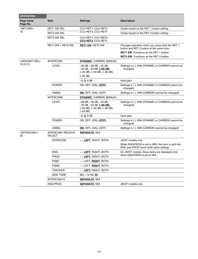
<RETURN>18
RET1 SW SEL CCU RET1, CCU RET2, CCU RET3, CCU RET4
Varies based on the RET 1 button setting.
RET2 SW SEL Varies based on the RET 2 button setting.
RET3 SW SEL CCU RET1, CCU RET2, CCU RET3, CCU RET4
RET1 SW + RET2 SW RET1 SW, RET3 SW Changes operation when you press both the RET 1 button and RET 2 button at the same time.
RET1 SW: Functions as the RET 1 button.
RET3 SW: Functions as the RET 3 button.
<HEADSET MIC>19 (U11)
INTERCOM1 DYNAMIC, CARBON, MANUAL
LEVEL –60 dB, –50 dB, –40 dB,–30 dB, –20 dB, (–60 dB), (–50 dB), (–40 dB), (–30 dB),
(–20 dB)
Settings in ( ): With DYNAMIC or CARBON (cannot be changed)
–6, 0, 6 dB Input gain
POWER ON, OFF, (ON), (OFF) Settings in ( ): With DYNAMIC or CARBON (cannot be changed)
UNBAL ON, OFF, (ON), (OFF) Settings in ( ): With CARBON (cannot be changed)
INTERCOM2 DYNAMIC, CARBON, MANUAL
LEVEL –60 dB, –50 dB, –40 dB,–30 dB, –20 dB, (–60 dB), (–50 dB), (–40 dB), (–30 dB), (–20 dB)
Settings in ( ): With DYNAMIC or CARBON (cannot be changed)
–6, 0, 6 dB Input gain
POWER ON, OFF, (ON), (OFF) Settings in ( ): With DYNAMIC or CARBON (cannot be changed)
UNBAL ON, OFF, (ON), (OFF) Settings in ( ): With CARBON (cannot be changed)
<INTERCOM1>20
INTERCOM1 RECEIVE SELECT
SEPARATE, MIX
INTERCOM ---, LEFT, RIGHT, BOTH JN/SY models only
When ENG/PROD is set to MIX, this item is split into ENG and PROD items (with same setting).
ENG ---, LEFT, RIGHT, BOTH On JN/SY models, these items are displayed only when ENG/PROD is set to MIX.PROD ---, LEFT, RIGHT, BOTH
PGM1 ---, LEFT, RIGHT, BOTH
PGM2 ---, LEFT, RIGHT, BOTH
TRACKER ---, LEFT, RIGHT, BOTH
SIDE TONE MU, 1 to 99, 50
INTERCOM1/2 SEPARATE, MIX
ENG/PROD SEPARATE, MIX JN/SY models only.
OPERATION
Page namePage No.
Item Settings Description
43
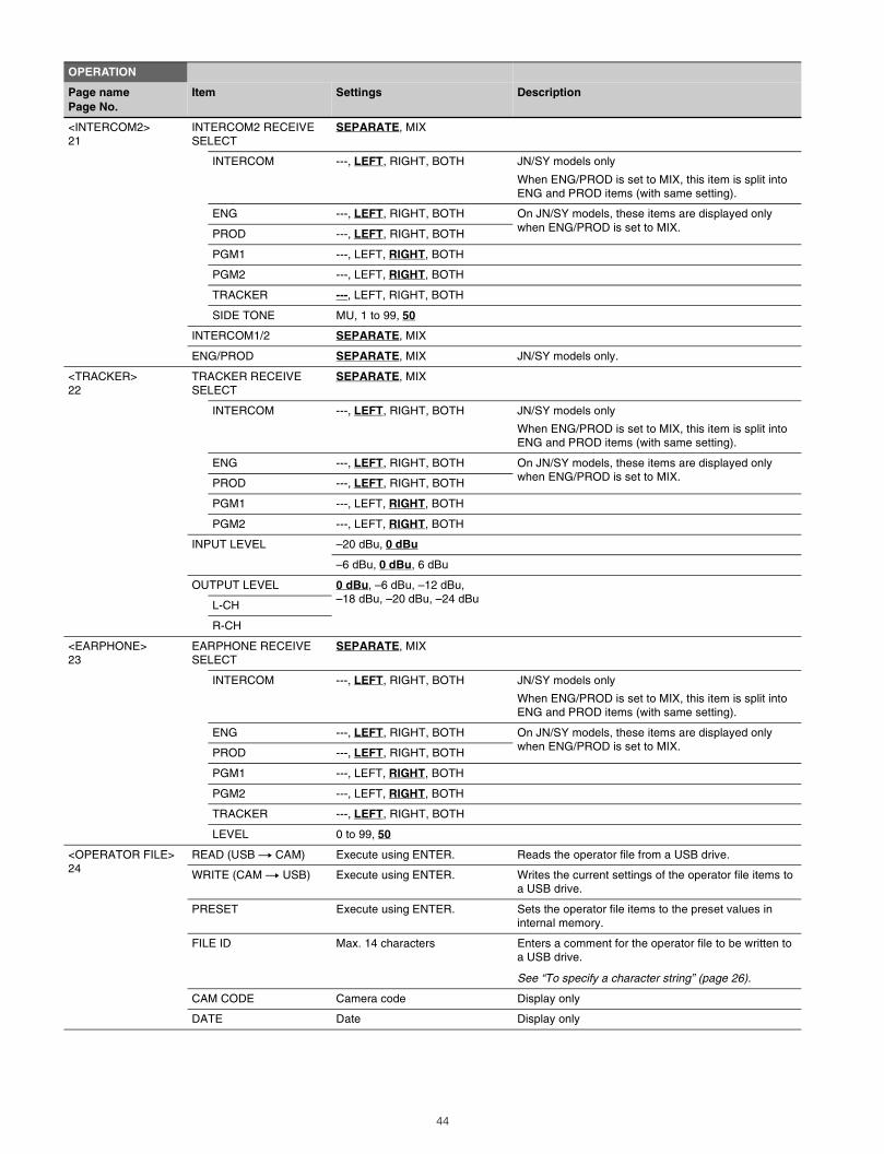
<INTERCOM2>21
INTERCOM2 RECEIVE SELECT
SEPARATE, MIX
INTERCOM ---, LEFT, RIGHT, BOTH JN/SY models only
When ENG/PROD is set to MIX, this item is split into ENG and PROD items (with same setting).
ENG ---, LEFT, RIGHT, BOTH On JN/SY models, these items are displayed only when ENG/PROD is set to MIX.PROD ---, LEFT, RIGHT, BOTH
PGM1 ---, LEFT, RIGHT, BOTH
PGM2 ---, LEFT, RIGHT, BOTH
TRACKER ---, LEFT, RIGHT, BOTH
SIDE TONE MU, 1 to 99, 50
INTERCOM1/2 SEPARATE, MIX
ENG/PROD SEPARATE, MIX JN/SY models only.
<TRACKER>22
TRACKER RECEIVE SELECT
SEPARATE, MIX
INTERCOM ---, LEFT, RIGHT, BOTH JN/SY models only
When ENG/PROD is set to MIX, this item is split into ENG and PROD items (with same setting).
ENG ---, LEFT, RIGHT, BOTH On JN/SY models, these items are displayed only when ENG/PROD is set to MIX.PROD ---, LEFT, RIGHT, BOTH
PGM1 ---, LEFT, RIGHT, BOTH
PGM2 ---, LEFT, RIGHT, BOTH
INPUT LEVEL –20 dBu, 0 dBu
–6 dBu, 0 dBu, 6 dBu
OUTPUT LEVEL 0 dBu, –6 dBu, –12 dBu, –18 dBu, –20 dBu, –24 dBuL-CH
R-CH
<EARPHONE>23
EARPHONE RECEIVE SELECT
SEPARATE, MIX
INTERCOM ---, LEFT, RIGHT, BOTH JN/SY models only
When ENG/PROD is set to MIX, this item is split into ENG and PROD items (with same setting).
ENG ---, LEFT, RIGHT, BOTH On JN/SY models, these items are displayed only when ENG/PROD is set to MIX.PROD ---, LEFT, RIGHT, BOTH
PGM1 ---, LEFT, RIGHT, BOTH
PGM2 ---, LEFT, RIGHT, BOTH
TRACKER ---, LEFT, RIGHT, BOTH
LEVEL 0 to 99, 50
<OPERATOR FILE>24
READ (USB t CAM) Execute using ENTER. Reads the operator file from a USB drive.
WRITE (CAM t USB) Execute using ENTER. Writes the current settings of the operator file items to a USB drive.
PRESET Execute using ENTER. Sets the operator file items to the preset values in internal memory.
FILE ID Max. 14 characters Enters a comment for the operator file to be written to a USB drive.
See “To specify a character string” (page 26).
CAM CODE Camera code Display only
DATE Date Display only
OPERATION
Page namePage No.
Item Settings Description
44
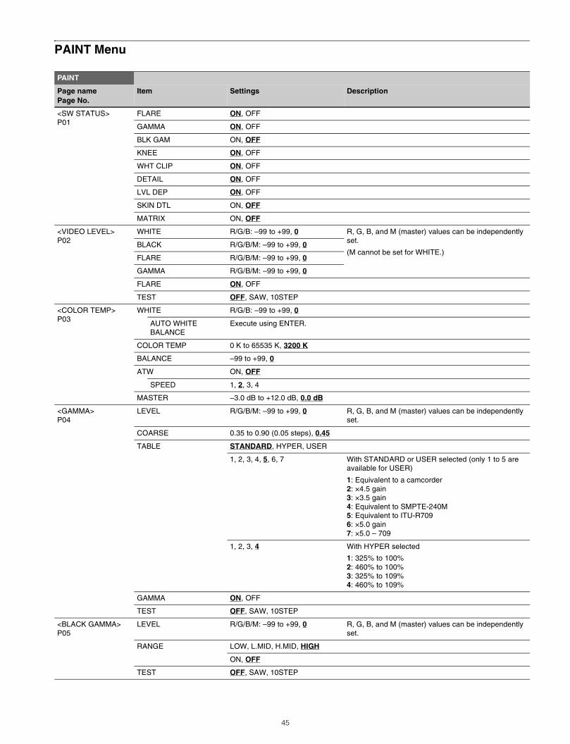
PAINT Menu
PAINT
Page namePage No.
Item Settings Description
<SW STATUS>P01
FLARE ON, OFF
GAMMA ON, OFF
BLK GAM ON, OFF
KNEE ON, OFF
WHT CLIP ON, OFF
DETAIL ON, OFF
LVL DEP ON, OFF
SKIN DTL ON, OFF
MATRIX ON, OFF
<VIDEO LEVEL>P02
WHITE R/G/B: –99 to +99, 0 R, G, B, and M (master) values can be independently set.
(M cannot be set for WHITE.)BLACK R/G/B/M: –99 to +99, 0
FLARE R/G/B/M: –99 to +99, 0
GAMMA R/G/B/M: –99 to +99, 0
FLARE ON, OFF
TEST OFF, SAW, 10STEP
<COLOR TEMP>P03
WHITE R/G/B: –99 to +99, 0
AUTO WHITE BALANCE
Execute using ENTER.
COLOR TEMP 0 K to 65535 K, 3200 K
BALANCE –99 to +99, 0
ATW ON, OFF
SPEED 1, 2, 3, 4
MASTER –3.0 dB to +12.0 dB, 0.0 dB
<GAMMA>P04
LEVEL R/G/B/M: –99 to +99, 0 R, G, B, and M (master) values can be independently set.
COARSE 0.35 to 0.90 (0.05 steps), 0.45
TABLE STANDARD, HYPER, USER
1, 2, 3, 4, 5, 6, 7 With STANDARD or USER selected (only 1 to 5 are available for USER)
1: Equivalent to a camcorder2: ×4.5 gain3: ×3.5 gain4: Equivalent to SMPTE-240M5: Equivalent to ITU-R7096: ×5.0 gain7: ×5.0 – 709
1, 2, 3, 4 With HYPER selected
1: 325% to 100%2: 460% to 100%3: 325% to 109%4: 460% to 109%
GAMMA ON, OFF
TEST OFF, SAW, 10STEP
<BLACK GAMMA>P05
LEVEL R/G/B/M: –99 to +99, 0 R, G, B, and M (master) values can be independently set.
RANGE LOW, L.MID, H.MID, HIGH
ON, OFF
TEST OFF, SAW, 10STEP
45
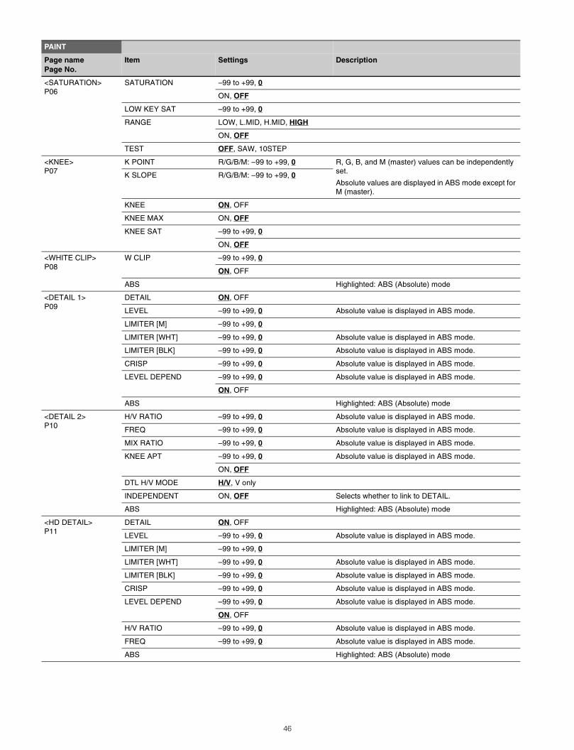
<SATURATION>P06
SATURATION –99 to +99, 0
ON, OFF
LOW KEY SAT –99 to +99, 0
RANGE LOW, L.MID, H.MID, HIGH
ON, OFF
TEST OFF, SAW, 10STEP
<KNEE>P07
K POINT R/G/B/M: –99 to +99, 0 R, G, B, and M (master) values can be independently set.
Absolute values are displayed in ABS mode except for M (master).
K SLOPE R/G/B/M: –99 to +99, 0
KNEE ON, OFF
KNEE MAX ON, OFF
KNEE SAT –99 to +99, 0
ON, OFF
<WHITE CLIP>P08
W CLIP –99 to +99, 0
ON, OFF
ABS Highlighted: ABS (Absolute) mode
<DETAIL 1>P09
DETAIL ON, OFF
LEVEL –99 to +99, 0 Absolute value is displayed in ABS mode.
LIMITER [M] –99 to +99, 0
LIMITER [WHT] –99 to +99, 0 Absolute value is displayed in ABS mode.
LIMITER [BLK] –99 to +99, 0 Absolute value is displayed in ABS mode.
CRISP –99 to +99, 0 Absolute value is displayed in ABS mode.
LEVEL DEPEND –99 to +99, 0 Absolute value is displayed in ABS mode.
ON, OFF
ABS Highlighted: ABS (Absolute) mode
<DETAIL 2>P10
H/V RATIO –99 to +99, 0 Absolute value is displayed in ABS mode.
FREQ –99 to +99, 0 Absolute value is displayed in ABS mode.
MIX RATIO –99 to +99, 0 Absolute value is displayed in ABS mode.
KNEE APT –99 to +99, 0 Absolute value is displayed in ABS mode.
ON, OFF
DTL H/V MODE H/V, V only
INDEPENDENT ON, OFF Selects whether to link to DETAIL.
ABS Highlighted: ABS (Absolute) mode
<HD DETAIL>P11
DETAIL ON, OFF
LEVEL –99 to +99, 0 Absolute value is displayed in ABS mode.
LIMITER [M] –99 to +99, 0
LIMITER [WHT] –99 to +99, 0 Absolute value is displayed in ABS mode.
LIMITER [BLK] –99 to +99, 0 Absolute value is displayed in ABS mode.
CRISP –99 to +99, 0 Absolute value is displayed in ABS mode.
LEVEL DEPEND –99 to +99, 0 Absolute value is displayed in ABS mode.
ON, OFF
H/V RATIO –99 to +99, 0 Absolute value is displayed in ABS mode.
FREQ –99 to +99, 0 Absolute value is displayed in ABS mode.
ABS Highlighted: ABS (Absolute) mode
PAINT
Page namePage No.
Item Settings Description
46
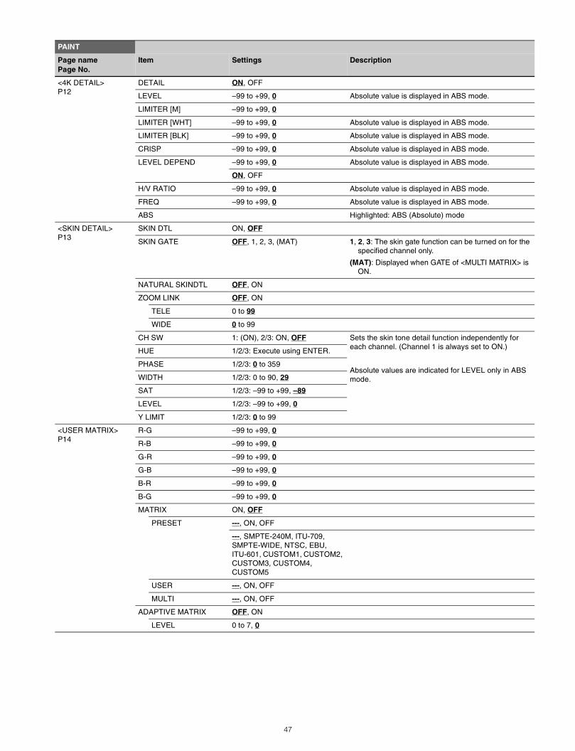
<4K DETAIL>P12
DETAIL ON, OFF
LEVEL –99 to +99, 0 Absolute value is displayed in ABS mode.
LIMITER [M] –99 to +99, 0
LIMITER [WHT] –99 to +99, 0 Absolute value is displayed in ABS mode.
LIMITER [BLK] –99 to +99, 0 Absolute value is displayed in ABS mode.
CRISP –99 to +99, 0 Absolute value is displayed in ABS mode.
LEVEL DEPEND –99 to +99, 0 Absolute value is displayed in ABS mode.
ON, OFF
H/V RATIO –99 to +99, 0 Absolute value is displayed in ABS mode.
FREQ –99 to +99, 0 Absolute value is displayed in ABS mode.
ABS Highlighted: ABS (Absolute) mode
<SKIN DETAIL>P13
SKIN DTL ON, OFF
SKIN GATE OFF, 1, 2, 3, (MAT) 1, 2, 3: The skin gate function can be turned on for the specified channel only.
(MAT): Displayed when GATE of <MULTI MATRIX> is ON.
NATURAL SKINDTL OFF, ON
ZOOM LINK OFF, ON
TELE 0 to 99
WIDE 0 to 99
CH SW 1: (ON), 2/3: ON, OFF Sets the skin tone detail function independently for each channel. (Channel 1 is always set to ON.)
Absolute values are indicated for LEVEL only in ABS mode.
HUE 1/2/3: Execute using ENTER.
PHASE 1/2/3: 0 to 359
WIDTH 1/2/3: 0 to 90, 29
SAT 1/2/3: –99 to +99, –89
LEVEL 1/2/3: –99 to +99, 0
Y LIMIT 1/2/3: 0 to 99
<USER MATRIX>P14
R-G –99 to +99, 0
R-B –99 to +99, 0
G-R –99 to +99, 0
G-B –99 to +99, 0
B-R –99 to +99, 0
B-G –99 to +99, 0
MATRIX ON, OFF
PRESET ---, ON, OFF
---, SMPTE-240M, ITU-709, SMPTE-WIDE, NTSC, EBU, ITU-601, CUSTOM1, CUSTOM2, CUSTOM3, CUSTOM4, CUSTOM5
USER ---, ON, OFF
MULTI ---, ON, OFF
ADAPTIVE MATRIX OFF, ON
LEVEL 0 to 7, 0
PAINT
Page namePage No.
Item Settings Description
47
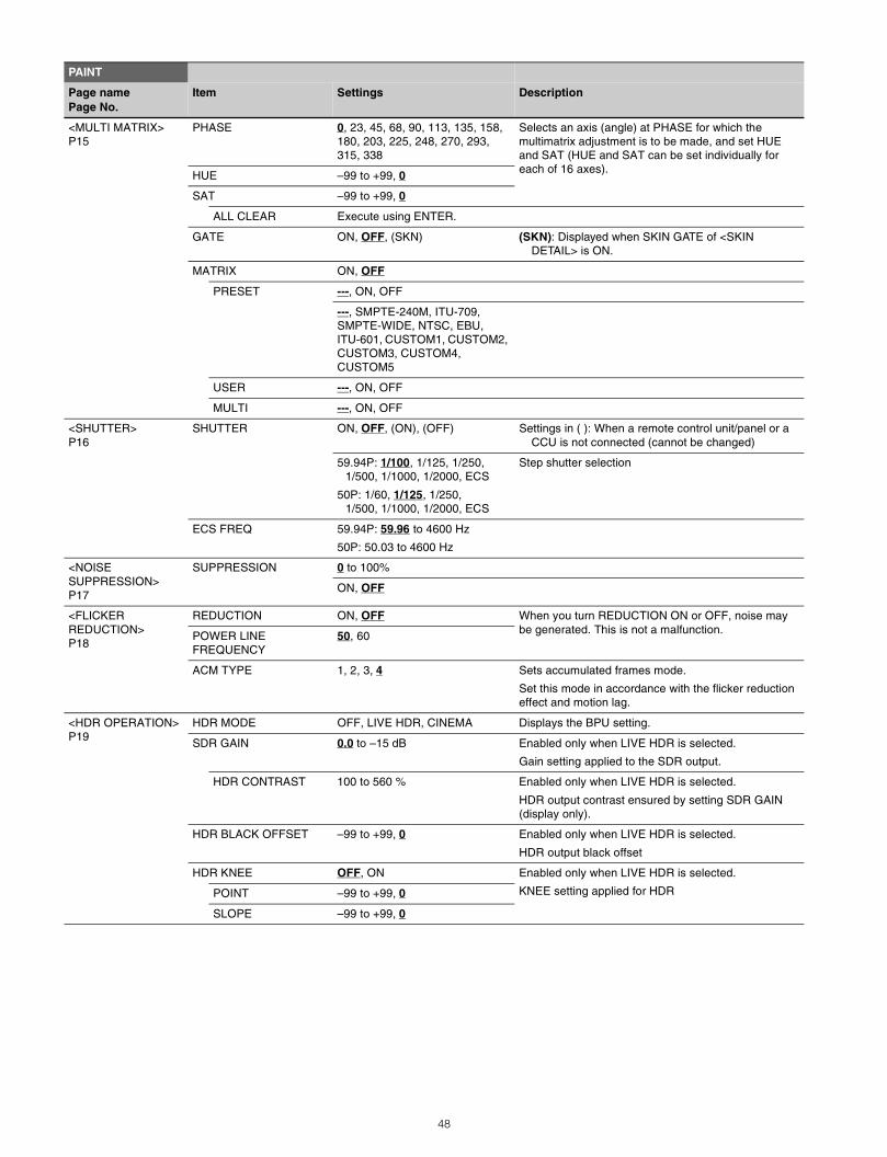
<MULTI MATRIX>P15
PHASE 0, 23, 45, 68, 90, 113, 135, 158, 180, 203, 225, 248, 270, 293, 315, 338
Selects an axis (angle) at PHASE for which the multimatrix adjustment is to be made, and set HUE and SAT (HUE and SAT can be set individually for each of 16 axes).HUE –99 to +99, 0
SAT –99 to +99, 0
ALL CLEAR Execute using ENTER.
GATE ON, OFF, (SKN) (SKN): Displayed when SKIN GATE of <SKIN DETAIL> is ON.
MATRIX ON, OFF
PRESET ---, ON, OFF
---, SMPTE-240M, ITU-709, SMPTE-WIDE, NTSC, EBU, ITU-601, CUSTOM1, CUSTOM2, CUSTOM3, CUSTOM4, CUSTOM5
USER ---, ON, OFF
MULTI ---, ON, OFF
<SHUTTER>P16
SHUTTER ON, OFF, (ON), (OFF) Settings in ( ): When a remote control unit/panel or a CCU is not connected (cannot be changed)
59.94P: 1/100, 1/125, 1/250, 1/500, 1/1000, 1/2000, ECS
50P: 1/60, 1/125, 1/250, 1/500, 1/1000, 1/2000, ECS
Step shutter selection
ECS FREQ 59.94P: 59.96 to 4600 Hz
50P: 50.03 to 4600 Hz
<NOISE SUPPRESSION> P17
SUPPRESSION 0 to 100%
ON, OFF
<FLICKER REDUCTION>P18
REDUCTION ON, OFFNoteWhen you turn REDUCTION ON or OFF, noise may be generated. This is not a malfunction.POWER LINE
FREQUENCY50, 60
ACM TYPE 1, 2, 3, 4 Sets accumulated frames mode.
Set this mode in accordance with the flicker reduction effect and motion lag.
<HDR OPERATION>P19
HDR MODE OFF, LIVE HDR, CINEMA Displays the BPU setting.
SDR GAIN 0.0 to –15 dB Enabled only when LIVE HDR is selected.
Gain setting applied to the SDR output.
HDR CONTRAST 100 to 560 % Enabled only when LIVE HDR is selected.
HDR output contrast ensured by setting SDR GAIN (display only).
HDR BLACK OFFSET –99 to +99, 0 Enabled only when LIVE HDR is selected.
HDR output black offset
HDR KNEE OFF, ON Enabled only when LIVE HDR is selected.
KNEE setting applied for HDRPOINT –99 to +99, 0
SLOPE –99 to +99, 0
PAINT
Page namePage No.
Item Settings Description
48
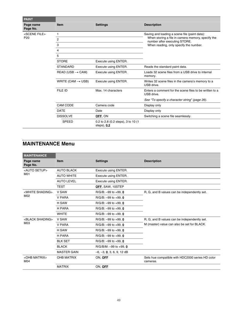
MAINTENANCE Menu
<SCENE FILE>P20
1 Saving and loading a scene file (paint data):When storing a file in camera memory, specify the number after executing STORE.When reading, only specify the number.
2
3
4
5
STORE Execute using ENTER.
STANDARD Execute using ENTER. Reads the standard paint data.
READ (USB t CAM) Execute using ENTER. Loads 32 scene files from a USB drive to internal memory.
WRITE (CAM t USB) Execute using ENTER. Writes 32 scene files in the camera’s memory to a USB drive.
FILE ID Max. 14 characters Enters a comment for the scene files to be written to a USB drive.
See “To specify a character string” (page 26).
CAM CODE Camera code Display only
DATE Date Display only
DISSOLVE OFF, ON Switching a scene file seamlessly.
SPEED 0.2 to 2.8 (0.2 steps), 3 to 10 (1 steps), 0.2
MAINTENANCE
Page namePage No.
Item Settings Description
<AUTO SETUP>M01
AUTO BLACK Execute using ENTER.
AUTO WHITE Execute using ENTER.
AUTO LEVEL Execute using ENTER.
TEST OFF, SAW, 10STEP
<WHITE SHADING>M02
V SAW R/G/B: –99 to +99, 0 R, G, and B values can be independently set.
V PARA R/G/B: –99 to +99, 0
H SAW R/G/B: –99 to +99, 0
H PARA R/G/B: –99 to +99, 0
WHITE R/G/B: –99 to +99, 0
<BLACK SHADING>M03
V SAW R/G/B: –99 to +99, 0 R, G, and B values can be independently set.
M (master) value can also be set for BLACK.V PARA R/G/B: –99 to +99, 0
H SAW R/G/B: –99 to +99, 0
H PARA R/G/B: –99 to +99, 0
BLK SET R/G/B: –99 to +99, 0
BLACK R/G/B/M: –99 to +99, 0
MASTER GAIN –6, –3, 0, 3, 6, 9, 12 dB
<OHB MATRIX>M04
OHB MATRIX ON, OFF Sets hue compatible with HDC2000 series HD color cameras.
MATRIX ON, OFF
PAINT
Page namePage No.
Item Settings Description
49
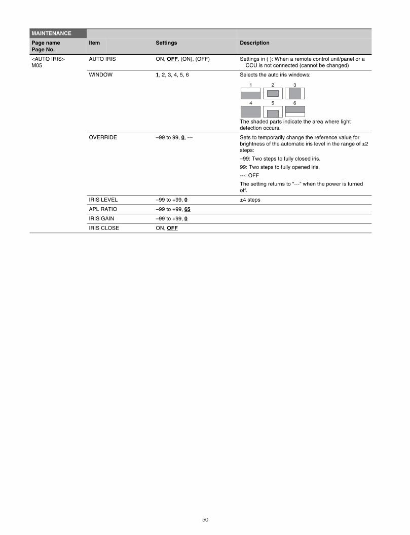
<AUTO IRIS>M05
AUTO IRIS ON, OFF, (ON), (OFF) Settings in ( ): When a remote control unit/panel or a CCU is not connected (cannot be changed)
WINDOW 1, 2, 3, 4, 5, 6 Selects the auto iris windows:
The shaded parts indicate the area where light detection occurs.
OVERRIDE –99 to 99, 0, --- Sets to temporarily change the reference value for brightness of the automatic iris level in the range of ±2 steps:
–99: Two steps to fully closed iris.
99: Two steps to fully opened iris.
---: OFF
The setting returns to “---” when the power is turned off.
IRIS LEVEL –99 to +99, 0 ±4 steps
APL RATIO –99 to +99, 65
IRIS GAIN –99 to +99, 0
IRIS CLOSE ON, OFF
MAINTENANCE
Page namePage No.
Item Settings Description
1 2 3
4 5 6
50
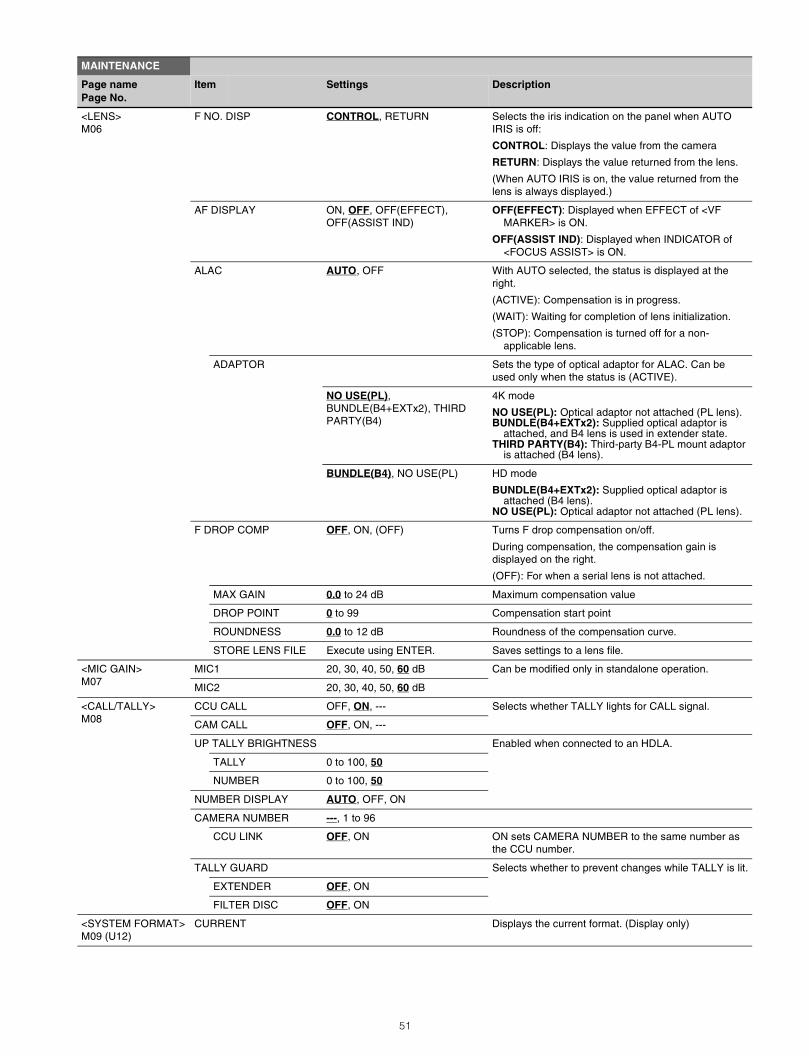
<LENS>M06
F NO. DISP CONTROL, RETURN Selects the iris indication on the panel when AUTO IRIS is off:
CONTROL: Displays the value from the camera
RETURN: Displays the value returned from the lens.
(When AUTO IRIS is on, the value returned from the lens is always displayed.)
AF DISPLAY ON, OFF, OFF(EFFECT), OFF(ASSIST IND)
OFF(EFFECT): Displayed when EFFECT of <VF MARKER> is ON.
OFF(ASSIST IND): Displayed when INDICATOR of <FOCUS ASSIST> is ON.
ALAC AUTO, OFF With AUTO selected, the status is displayed at the right.
(ACTIVE): Compensation is in progress.
(WAIT): Waiting for completion of lens initialization.
(STOP): Compensation is turned off for a non-applicable lens.
ADAPTOR Sets the type of optical adaptor for ALAC. Can be used only when the status is (ACTIVE).
NO USE(PL), BUNDLE(B4+EXTx2), THIRD PARTY(B4)
4K mode
NO USE(PL): Optical adaptor not attached (PL lens).BUNDLE(B4+EXTx2): Supplied optical adaptor is
attached, and B4 lens is used in extender state.THIRD PARTY(B4): Third-party B4-PL mount adaptor
is attached (B4 lens).
BUNDLE(B4), NO USE(PL) HD mode
BUNDLE(B4+EXTx2): Supplied optical adaptor is attached (B4 lens).
NO USE(PL): Optical adaptor not attached (PL lens).
F DROP COMP OFF, ON, (OFF) Turns F drop compensation on/off.
During compensation, the compensation gain is displayed on the right.
(OFF): For when a serial lens is not attached.
MAX GAIN 0.0 to 24 dB Maximum compensation value
DROP POINT 0 to 99 Compensation start point
ROUNDNESS 0.0 to 12 dB Roundness of the compensation curve.
STORE LENS FILE Execute using ENTER. Saves settings to a lens file.
<MIC GAIN>M07
MIC1 20, 30, 40, 50, 60 dB Can be modified only in standalone operation.
MIC2 20, 30, 40, 50, 60 dB
<CALL/TALLY>M08
CCU CALL OFF, ON, --- Selects whether TALLY lights for CALL signal.
CAM CALL OFF, ON, ---
UP TALLY BRIGHTNESS Enabled when connected to an HDLA.
TALLY 0 to 100, 50
NUMBER 0 to 100, 50
NUMBER DISPLAY AUTO, OFF, ON
CAMERA NUMBER ---, 1 to 96
CCU LINK OFF, ON ON sets CAMERA NUMBER to the same number as the CCU number.
TALLY GUARD Selects whether to prevent changes while TALLY is lit.
EXTENDER OFF, ON
FILTER DISC OFF, ON
<SYSTEM FORMAT>M09 (U12)
CURRENT Displays the current format. (Display only)
MAINTENANCE
Page namePage No.
Item Settings Description
51
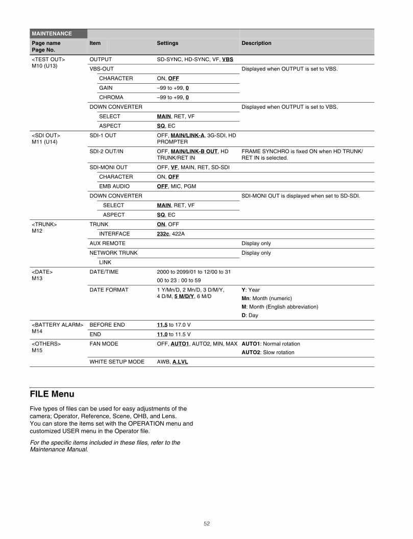
FILE Menu
Five types of files can be used for easy adjustments of the camera; Operator, Reference, Scene, OHB, and Lens.You can store the items set with the OPERATION menu and customized USER menu in the Operator file.
For the specific items included in these files, refer to the Maintenance Manual.
<TEST OUT>M10 (U13)
OUTPUT SD-SYNC, HD-SYNC, VF, VBS
VBS-OUT Displayed when OUTPUT is set to VBS.
CHARACTER ON, OFF
GAIN –99 to +99, 0
CHROMA –99 to +99, 0
DOWN CONVERTER Displayed when OUTPUT is set to VBS.
SELECT MAIN, RET, VF
ASPECT SQ, EC
<SDI OUT>M11 (U14)
SDI-1 OUT OFF, MAIN/LINK-A, 3G-SDI, HD PROMPTER
SDI-2 OUT/IN OFF, MAIN/LINK-B OUT, HD TRUNK/RET IN
FRAME SYNCHRO is fixed ON when HD TRUNK/RET IN is selected.
SDI-MONI OUT OFF, VF, MAIN, RET, SD-SDI
CHARACTER ON, OFF
EMB AUDIO OFF, MIC, PGM
DOWN CONVERTER SDI-MONI OUT is displayed when set to SD-SDI.
SELECT MAIN, RET, VF
ASPECT SQ, EC
<TRUNK>M12
TRUNK ON, OFF
INTERFACE 232c, 422A
AUX REMOTE Display only
NETWORK TRUNK Display only
LINK
<DATE>M13
DATE/TIME 2000 to 2099/01 to 12/00 to 31
00 to 23 : 00 to 59
DATE FORMAT 1 Y/Mn/D, 2 Mn/D, 3 D/M/Y, 4 D/M, 5 M/D/Y, 6 M/D
Y: Year
Mn: Month (numeric)
M: Month (English abbreviation)
D: Day
<BATTERY ALARM>M14
BEFORE END 11.5 to 17.0 V
END 11.0 to 11.5 V
<OTHERS>M15
FAN MODE OFF, AUTO1, AUTO2, MIN, MAX AUTO1: Normal rotation
AUTO2: Slow rotation
WHITE SETUP MODE AWB, A.LVL
MAINTENANCE
Page namePage No.
Item Settings Description
52
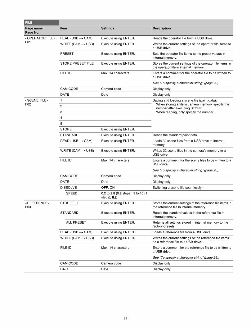
FILE
Page namePage No.
Item Settings Description
<OPERATOR FILE>F01
READ (USB t CAM) Execute using ENTER. Reads the operator file from a USB drive.
WRITE (CAM t USB) Execute using ENTER. Writes the current settings of the operator file items to a USB drive.
PRESET Execute using ENTER. Sets the operator file items to the preset values in internal memory.
STORE PRESET FILE Execute using ENTER. Stores the current settings of the operator file items in the operator file in internal memory.
FILE ID Max. 14 characters Enters a comment for the operator file to be written to a USB drive.
See “To specify a character string” (page 26).
CAM CODE Camera code Display only
DATE Date Display only
<SCENE FILE>F02
1 Saving and loading a scene file (paint data):When storing a file in camera memory, specify the number after executing STORE.When reading, only specify the number.
2
3
4
5
STORE Execute using ENTER.
STANDARD Execute using ENTER. Reads the standard paint data.
READ (USB t CAM) Execute using ENTER. Loads 32 scene files from a USB drive to internal memory.
WRITE (CAM t USB) Execute using ENTER. Writes 32 scene files in the camera’s memory to a USB drive.
FILE ID Max. 14 characters Enters a comment for the scene files to be written to a USB drive.
See “To specify a character string” (page 26).
CAM CODE Camera code Display only
DATE Date Display only
DISSOLVE OFF, ON Switching a scene file seamlessly.
SPEED 0.2 to 2.8 (0.2 steps), 3 to 10 (1 steps), 0.2
<REFERENCE>F03
STORE FILE Execute using ENTER. Stores the current settings of the reference file items in the reference file in internal memory.
STANDARD Execute using ENTER. Reads the standard values in the reference file in internal memory.
ALL PRESET Execute using ENTER. Returns all settings stored in internal memory to the factory-presets.
READ (USB t CAM) Execute using ENTER. Loads a reference file from a USB drive.
WRITE (CAM t USB) Execute using ENTER. Writes the current settings of the reference file items as a reference file to a USB drive.
FILE ID Max. 14 characters Enters a comment for the reference file to be written to a USB drive.
See “To specify a character string” (page 26).
CAM CODE Camera code Display only
DATE Date Display only
53
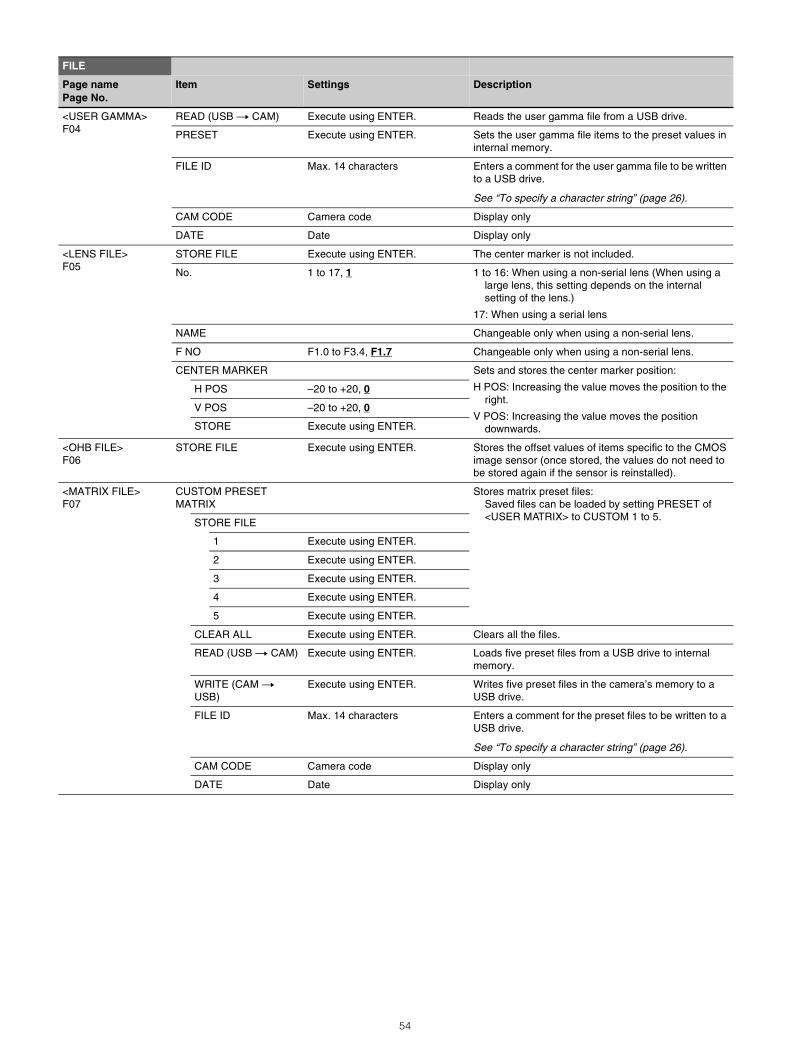
<USER GAMMA>F04
READ (USB t CAM) Execute using ENTER. Reads the user gamma file from a USB drive.
PRESET Execute using ENTER. Sets the user gamma file items to the preset values in internal memory.
FILE ID Max. 14 characters Enters a comment for the user gamma file to be written to a USB drive.
See “To specify a character string” (page 26).
CAM CODE Camera code Display only
DATE Date Display only
<LENS FILE>F05
STORE FILE Execute using ENTER. The center marker is not included.
No. 1 to 17, 1 1 to 16: When using a non-serial lens (When using a large lens, this setting depends on the internal setting of the lens.)
17: When using a serial lens
NAME Changeable only when using a non-serial lens.
F NO F1.0 to F3.4, F1.7 Changeable only when using a non-serial lens.
CENTER MARKER Sets and stores the center marker position:
H POS: Increasing the value moves the position to the right.
V POS: Increasing the value moves the position downwards.
H POS –20 to +20, 0
V POS –20 to +20, 0
STORE Execute using ENTER.
<OHB FILE>F06
STORE FILE Execute using ENTER. Stores the offset values of items specific to the CMOS image sensor (once stored, the values do not need to be stored again if the sensor is reinstalled).
<MATRIX FILE>F07
CUSTOM PRESET MATRIX
Stores matrix preset files:Saved files can be loaded by setting PRESET of <USER MATRIX> to CUSTOM 1 to 5.STORE FILE
1 Execute using ENTER.
2 Execute using ENTER.
3 Execute using ENTER.
4 Execute using ENTER.
5 Execute using ENTER.
CLEAR ALL Execute using ENTER. Clears all the files.
READ (USB t CAM) Execute using ENTER. Loads five preset files from a USB drive to internal memory.
WRITE (CAM t USB)
Execute using ENTER. Writes five preset files in the camera’s memory to a USB drive.
FILE ID Max. 14 characters Enters a comment for the preset files to be written to a USB drive.
See “To specify a character string” (page 26).
CAM CODE Camera code Display only
DATE Date Display only
FILE
Page namePage No.
Item Settings Description
54
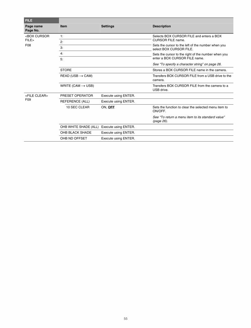
<BOX CURSOR FILE>
F08
1: Selects BOX CURSOR FILE and enters a BOX CURSOR FILE name.
Sets the cursor to the left of the number when you select BOX CURSOR FILE.
Sets the cursor to the right of the number when you enter a BOX CURSOR FILE name.
See “To specify a character string” on page 26.
2:
3:
4:
5:
STORE Stores a BOX CURSOR FILE name in the camera.
READ (USB t CAM) Transfers BOX CURSOR FILE from a USB drive to the camera.
WRITE (CAM t USB) Transfers BOX CURSOR FILE from the camera to a USB drive.
<FILE CLEAR>F09
PRESET OPERATOR Execute using ENTER.
REFERENCE (ALL) Execute using ENTER.
10 SEC CLEAR ON, OFF Sets the function to clear the selected menu item to ON/OFF.
See “To return a menu item to its standard value” (page 26).
OHB WHITE SHADE (ALL) Execute using ENTER.
OHB BLACK SHADE Execute using ENTER.
OHB ND OFFSET Execute using ENTER.
FILE
Page namePage No.
Item Settings Description
55
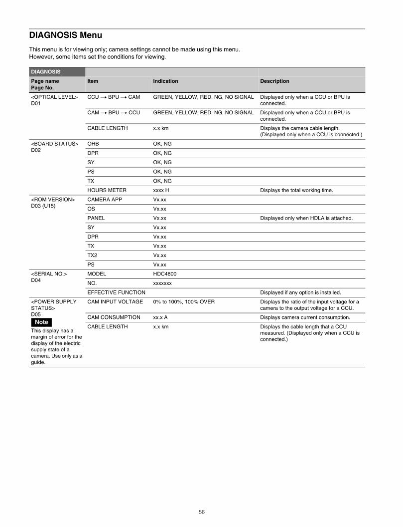
DIAGNOSIS Menu
This menu is for viewing only; camera settings cannot be made using this menu.However, some items set the conditions for viewing.
DIAGNOSIS
Page namePage No.
Item Indication Description
<OPTICAL LEVEL>D01
CCU t BPU t CAM GREEN, YELLOW, RED, NG, NO SIGNAL Displayed only when a CCU or BPU is connected.
CAM t BPU t CCU GREEN, YELLOW, RED, NG, NO SIGNAL Displayed only when a CCU or BPU is connected.
CABLE LENGTH x.x km Displays the camera cable length. (Displayed only when a CCU is connected.)
<BOARD STATUS>D02
OHB OK, NG
DPR OK, NG
SY OK, NG
PS OK, NG
TX OK, NG
HOURS METER xxxx H Displays the total working time.
<ROM VERSION>D03 (U15)
CAMERA APP Vx.xx
OS Vx.xx
PANEL Vx.xx Displayed only when HDLA is attached.
SY Vx.xx
DPR Vx.xx
TX Vx.xx
TX2 Vx.xx
PS Vx.xx
<SERIAL NO.>D04
MODEL HDC4800
NO. xxxxxxx
EFFECTIVE FUNCTION Displayed if any option is installed.
<POWER SUPPLY STATUS>D05
This display has a margin of error for the display of the electric supply state of a camera. Use only as a guide.
CAM INPUT VOLTAGE 0% to 100%, 100% OVER Displays the ratio of the input voltage for a camera to the output voltage for a CCU.
CAM CONSUMPTION xx.x A Displays camera current consumption.
CABLE LENGTH x.x km Displays the cable length that a CCU measured. (Displayed only when a CCU is connected.)
Note
56
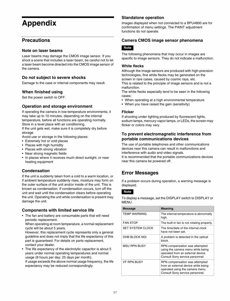
Appendix
Precautions
Note on laser beamsLaser beams may damage the CMOS image sensor. If you shoot a scene that includes a laser beam, be careful not to let a laser beam become directed into the CMOS image sensor of the camera.
Do not subject to severe shocksDamage to the case or internal components may result.
When finished usingSet the power switch to OFF.
Operation and storage environmentIf operating the camera in low-temperature environments, it may take up to 10 minutes, depending on the internal temperature, before all functions are operating normally.Store in a level place with air conditioning.If the unit gets wet, make sure it is completely dry before storage.Avoid use or storage in the following places:• Extremely hot or cold places• Places with high humidity• Places with strong vibration• Near strong magnetic fields• In places where it receives much direct sunlight, or near
heating equipment
CondensationIf the unit is suddenly taken from a cold to a warm location, or if ambient temperature suddenly rises, moisture may form on the outer surface of the unit and/or inside of the unit. This is known as condensation. If condensation occurs, turn off the unit and wait until the condensation clears before operating the unit. Operating the unit while condensation is present may damage the unit.
Components with limited service life• The fan and battery are consumable parts that will need
periodic replacement.When operating at room temperature, a normal replacement cycle will be about 5 years. However, this replacement cycle represents only a general guideline and does not imply that the life expectancy of this part is guaranteed. For details on parts replacement, contact your dealer.
• The life expectancy of the electrolytic capacitor is about 5 years under normal operating temperatures and normal usage (8 hours per day; 25 days per month).If usage exceeds the above normal usage frequency, the life expectancy may be reduced correspondingly.
Standalone operationImages displayed when not connected to a BPU4800 are for confirmation of menu settings. The PAINT adjustment functions do not operate.
Camera CMOS image sensor phenomena
The following phenomena that may occur in images are specific to image sensors. They do not indicate a malfunction.
White flecksAlthough the image sensors are produced with high-precision technologies, fine white flecks may be generated on the screen in rare cases, caused by cosmic rays, etc.This is related to the principle of image sensors and is not a malfunction.The white flecks especially tend to be seen in the following cases:• When operating at a high environmental temperature• When you have raised the gain (sensitivity)
FlickerIf shooting under lighting produced by fluorescent lights, sodium lamps, mercury-vapor lamps, or LEDs, the screen may flicker or colors may vary.
To prevent electromagnetic interference from portable communications devicesThe use of portable telephones and other communications devices near this camera can result in malfunctions and interference with audio and video signals.It is recommended that the portable communications devices near this camera be powered off.
Error Messages
If a problem occurs during operation, a warning message is displayed.
To display a message, set the DISPLAY switch to DISPLAY or MENU.
Note
Note
Message Meaning
TEMP WARNING The internal temperature is abnormally high.
FAN STOP The built-in fan is not rotating properly.
SET SYSTEM CLOCK The time/date of the internal clock have not been set.
OHB BLOCK NG! A problem is detected in the optical block.
MSU RPN BUSY RPN compensation was attempted using the camera menu while being operated from an external device. Consult Sony service personnel.
VF RPN BUSY RPN compensation was attempted from an external device while being operated using the camera menu. Consult Sony service personnel.
57
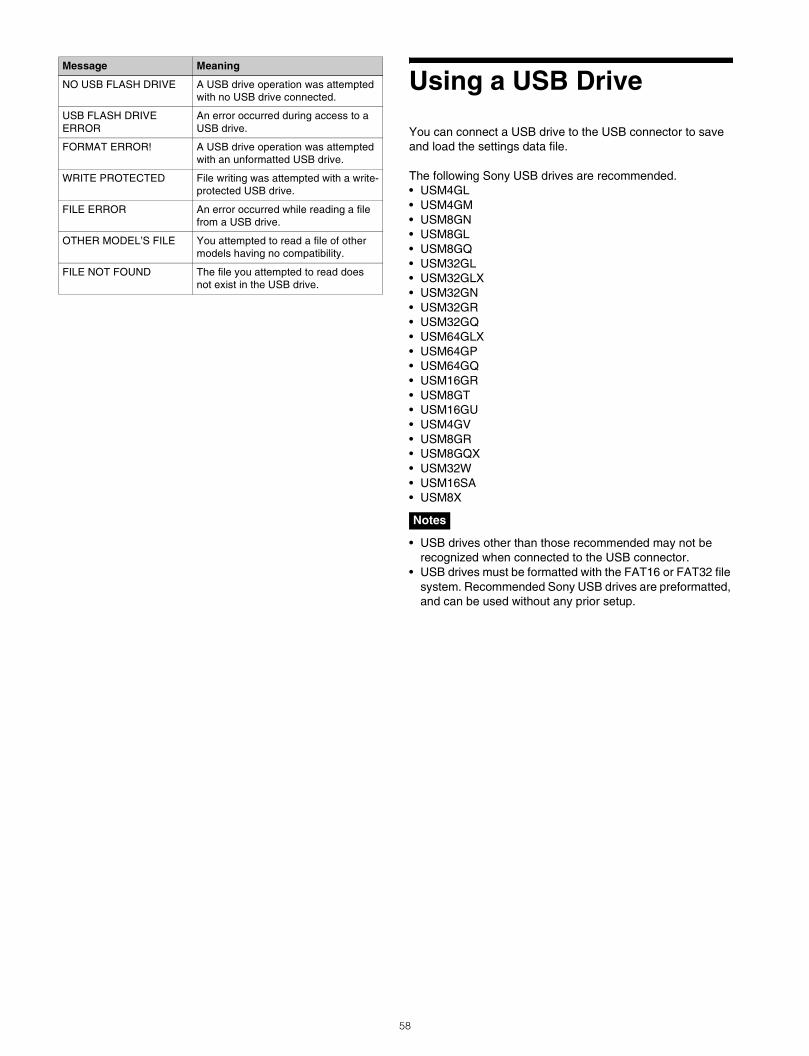
Using a USB Drive
You can connect a USB drive to the USB connector to save and load the settings data file.
The following Sony USB drives are recommended.• USM4GL• USM4GM• USM8GN• USM8GL• USM8GQ• USM32GL• USM32GLX• USM32GN• USM32GR• USM32GQ• USM64GLX• USM64GP• USM64GQ• USM16GR• USM8GT• USM16GU• USM4GV• USM8GR• USM8GQX• USM32W• USM16SA• USM8X
• USB drives other than those recommended may not be recognized when connected to the USB connector.
• USB drives must be formatted with the FAT16 or FAT32 file system. Recommended Sony USB drives are preformatted, and can be used without any prior setup.
NO USB FLASH DRIVE A USB drive operation was attempted with no USB drive connected.
USB FLASH DRIVE ERROR
An error occurred during access to a USB drive.
FORMAT ERROR! A USB drive operation was attempted with an unformatted USB drive.
WRITE PROTECTED File writing was attempted with a write-protected USB drive.
FILE ERROR An error occurred while reading a file from a USB drive.
OTHER MODEL’S FILE You attempted to read a file of other models having no compatibility.
FILE NOT FOUND The file you attempted to read does not exist in the USB drive.
Message Meaning
Notes
58
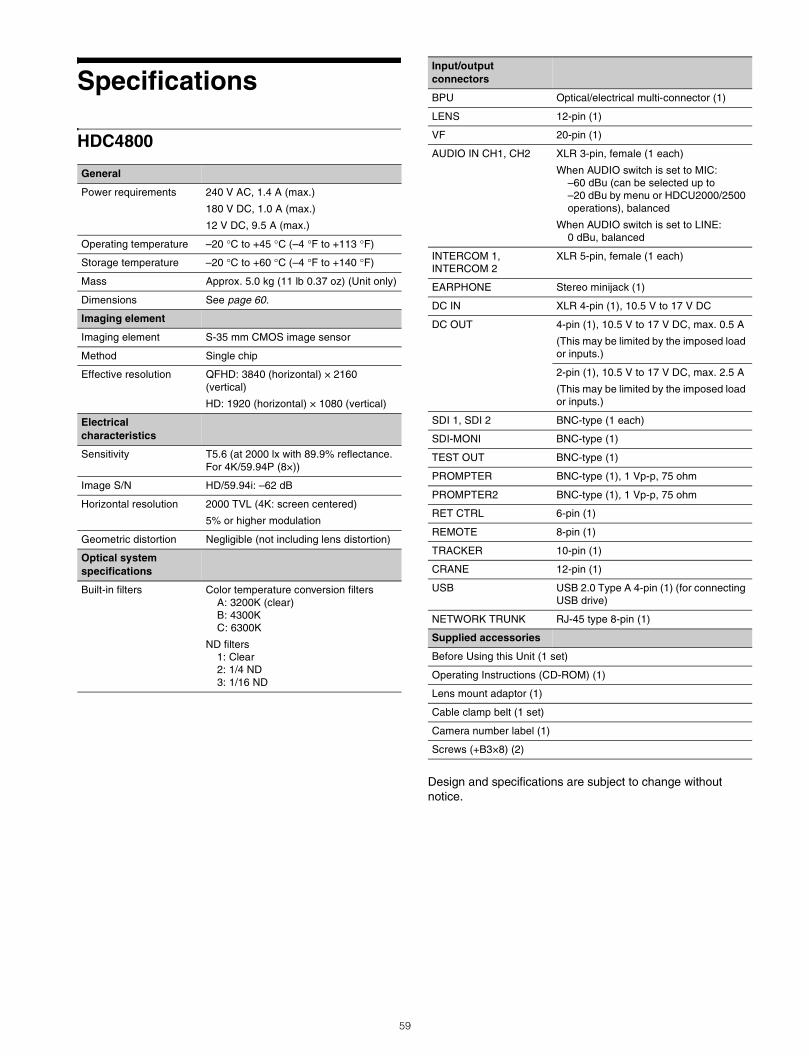
Specifications
HDC4800
Design and specifications are subject to change without notice.
General
Power requirements 240 V AC, 1.4 A (max.)
180 V DC, 1.0 A (max.)
12 V DC, 9.5 A (max.)
Operating temperature –20 °C to +45 °C (–4 °F to +113 °F)
Storage temperature –20 °C to +60 °C (–4 °F to +140 °F)
Mass Approx. 5.0 kg (11 lb 0.37 oz) (Unit only)
Dimensions See page 60.
Imaging element
Imaging element S-35 mm CMOS image sensor
Method Single chip
Effective resolution QFHD: 3840 (horizontal) × 2160 (vertical)
HD: 1920 (horizontal) × 1080 (vertical)
Electrical characteristics
Sensitivity T5.6 (at 2000 lx with 89.9% reflectance.For 4K/59.94P (8×))
Image S/N HD/59.94i: –62 dB
Horizontal resolution 2000 TVL (4K: screen centered)
5% or higher modulation
Geometric distortion Negligible (not including lens distortion)
Optical system specifications
Built-in filters Color temperature conversion filtersA: 3200K (clear)B: 4300KC: 6300K
ND filters1: Clear2: 1/4 ND3: 1/16 ND
Input/output connectors
BPU Optical/electrical multi-connector (1)
LENS 12-pin (1)
VF 20-pin (1)
AUDIO IN CH1, CH2 XLR 3-pin, female (1 each)
When AUDIO switch is set to MIC: –60 dBu (can be selected up to –20 dBu by menu or HDCU2000/2500 operations), balanced
When AUDIO switch is set to LINE:0 dBu, balanced
INTERCOM 1, INTERCOM 2
XLR 5-pin, female (1 each)
EARPHONE Stereo minijack (1)
DC IN XLR 4-pin (1), 10.5 V to 17 V DC
DC OUT 4-pin (1), 10.5 V to 17 V DC, max. 0.5 A
(This may be limited by the imposed load or inputs.)
2-pin (1), 10.5 V to 17 V DC, max. 2.5 A
(This may be limited by the imposed load or inputs.)
SDI 1, SDI 2 BNC-type (1 each)
SDI-MONI BNC-type (1)
TEST OUT BNC-type (1)
PROMPTER BNC-type (1), 1 Vp-p, 75 ohm
PROMPTER2 BNC-type (1), 1 Vp-p, 75 ohm
RET CTRL 6-pin (1)
REMOTE 8-pin (1)
TRACKER 10-pin (1)
CRANE 12-pin (1)
USB USB 2.0 Type A 4-pin (1) (for connecting USB drive)
NETWORK TRUNK RJ-45 type 8-pin (1)
Supplied accessories
Before Using this Unit (1 set)
Operating Instructions (CD-ROM) (1)
Lens mount adaptor (1)
Cable clamp belt (1 set)
Camera number label (1)
Screws (+B3×8) (2)
59
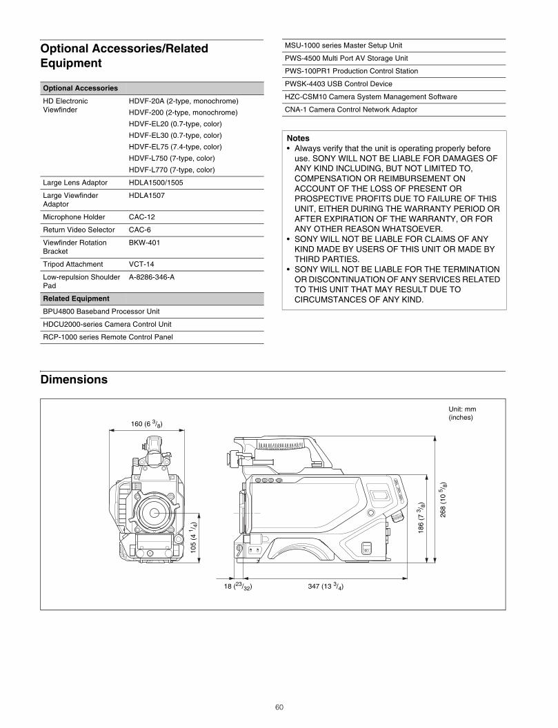
Optional Accessories/Related Equipment
Dimensions
Optional Accessories
HD Electronic Viewfinder
HDVF-20A (2-type, monochrome)
HDVF-200 (2-type, monochrome)
HDVF-EL20 (0.7-type, color)
HDVF-EL30 (0.7-type, color)
HDVF-EL75 (7.4-type, color)
HDVF-L750 (7-type, color)
HDVF-L770 (7-type, color)
Large Lens Adaptor HDLA1500/1505
Large Viewfinder Adaptor
HDLA1507
Microphone Holder CAC-12
Return Video Selector CAC-6
Viewfinder Rotation Bracket
BKW-401
Tripod Attachment VCT-14
Low-repulsion Shoulder Pad
A-8286-346-A
Related Equipment
BPU4800 Baseband Processor Unit
HDCU2000-series Camera Control Unit
RCP-1000 series Remote Control Panel
MSU-1000 series Master Setup Unit
PWS-4500 Multi Port AV Storage Unit
PWS-100PR1 Production Control Station
PWSK-4403 USB Control Device
HZC-CSM10 Camera System Management Software
CNA-1 Camera Control Network Adaptor
Notes• Always verify that the unit is operating properly before
use. SONY WILL NOT BE LIABLE FOR DAMAGES OF ANY KIND INCLUDING, BUT NOT LIMITED TO, COMPENSATION OR REIMBURSEMENT ON ACCOUNT OF THE LOSS OF PRESENT OR PROSPECTIVE PROFITS DUE TO FAILURE OF THIS UNIT, EITHER DURING THE WARRANTY PERIOD OR AFTER EXPIRATION OF THE WARRANTY, OR FOR ANY OTHER REASON WHATSOEVER.
• SONY WILL NOT BE LIABLE FOR CLAIMS OF ANY KIND MADE BY USERS OF THIS UNIT OR MADE BY THIRD PARTIES.
• SONY WILL NOT BE LIABLE FOR THE TERMINATION OR DISCONTINUATION OF ANY SERVICES RELATED TO THIS UNIT THAT MAY RESULT DUE TO CIRCUMSTANCES OF ANY KIND.
Unit: mm (inches)
160 (6 3/8)
347 (13 3/4)
268
(10
5 /8)
186
(7 3 /
8)
105
(4 1 /
4)
18 (23/32)
60