Embed Size (px)
Citation preview
2017-05-26 18:11 1/22 Color Control GX manual
Victron Energy - https://www.victronenergy.com/live/
Color Control GX manual
Note: this manual corresponds to the latest software. When internet connected, the device will updateto the latest version automatically. Check our blog posts for the latest firmware:https://www.victronenergy.com/blog/category/firmware-software/
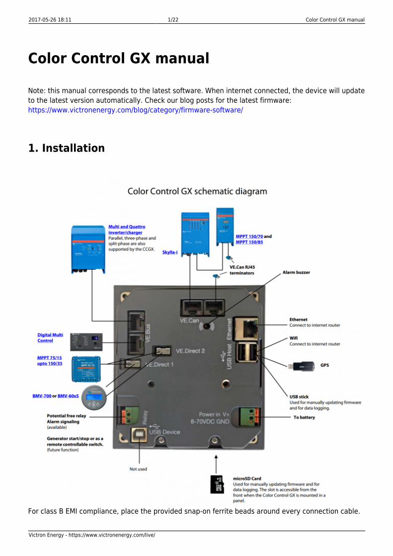
1. Installation
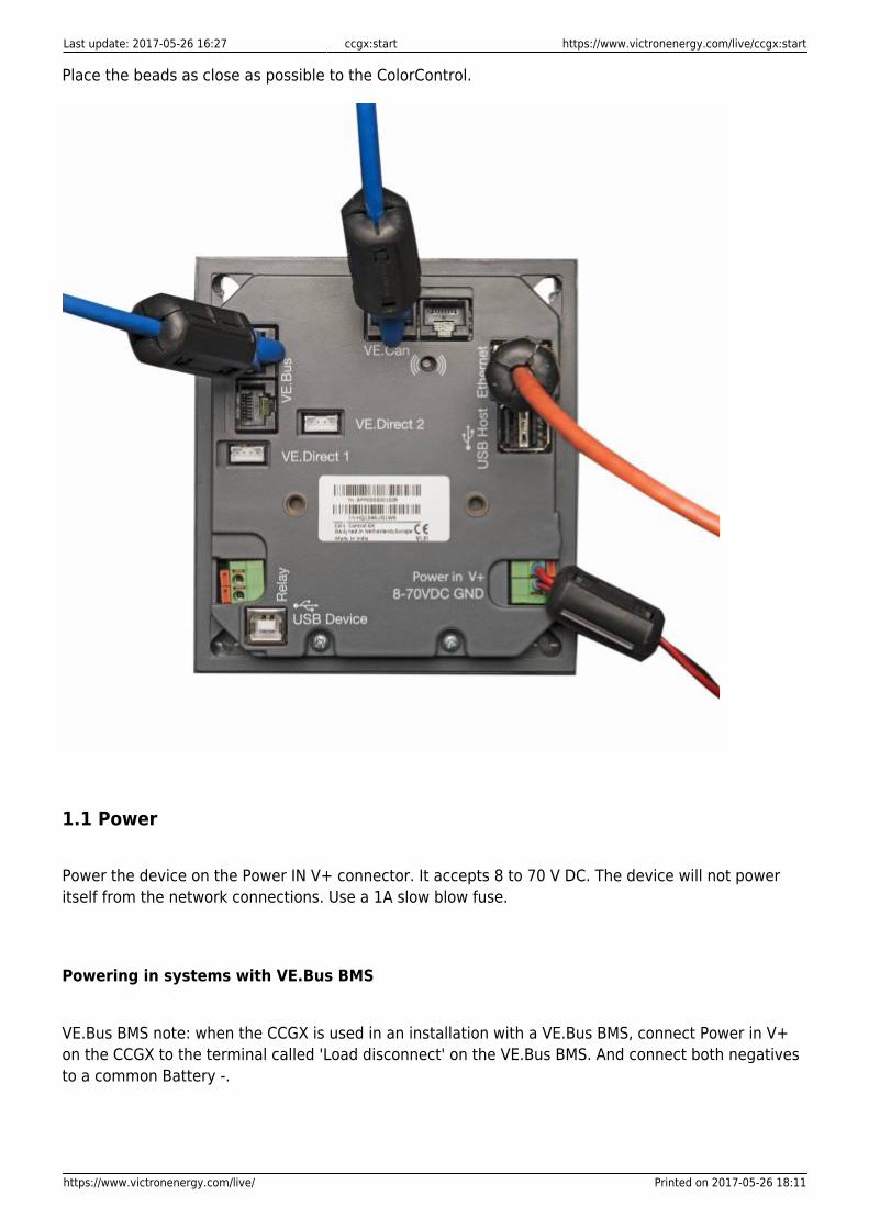
For class B EMI compliance, place the provided snap-on ferrite beads around every connection cable.
Last update: 2017-05-26 16:27 ccgx:start https://www.victronenergy.com/live/ccgx:start
https://www.victronenergy.com/live/ Printed on 2017-05-26 18:11
Place the beads as close as possible to the ColorControl.
1.1 Power
Power the device on the Power IN V+ connector. It accepts 8 to 70 V DC. The device will not poweritself from the network connections. Use a 1A slow blow fuse.
Powering in systems with VE.Bus BMS
VE.Bus BMS note: when the CCGX is used in an installation with a VE.Bus BMS, connect Power in V+on the CCGX to the terminal called 'Load disconnect' on the VE.Bus BMS. And connect both negativesto a common Battery -.
2017-05-26 18:11 3/22 Color Control GX manual
Victron Energy - https://www.victronenergy.com/live/
Powering from AC-out of a VE.Bus Inverter, Multi or Quattro
If you power the CCGX from an AC adaptor connected to the AC-out of VE.Bus products (Inverter,Multi or Quattro), then a deadlock will happen after the VE.Bus products are powered down for anyreason (after any operational fault or during a black start). The VE.Bus devices will inhibit their bootprocess until the CCGX is powered up, but the CCGX will not boot until it has power. This deadlock canbe verified by briefly unplugging the CCGX VE.Bus cable and observing that the VE.Bus productsimmediately start to boot.
This deadlock can be avoided in two ways:
Power the CCGX from the battery; or●
Cut pin 7 in the VE.Bus cable connected to the CCGX●
Cutting pin 7 of the VE.Bus cable to the CCGX (brown/white according to standard RJ45 ethernet cablecolour coding) allows the VE.Bus products to start up without waiting for the CCGX to boot up first.
The disadvantage of cutting that pin is that switching the VE.Bus device off will be less effective:though it will stop charging and inverting, it is still in standby mode and therefore its current draw onthe battery is higher than in a system with pin 7 in place. Typically only relevant in Marine orAutomotive systems, where it is normal to regularly switch the VE.Bus device off. For those types ofsystems, do not cut pin 7, but simply power the CCGX from the battery.
Isolation
Because the CCGX is connected to many different products, ensure that proper care is taken withisolation to prevent ground loops. In 99% of installations this will not be a problem.
The VE.Bus ports are isolated●
The VE.Direct ports are isolated●
The VE.Can ports are isolated●
The USB ports are not isolated. Connecting a Wi-Fi Dongle or GPS Dongle does not create a problem,●
since it is not connected to another power supply. Even though there will be ground loop when youmount a separately powered USB hub, we did extensive testing and it did not cause any issuesThe Ethernet port is isolated, except for the shield: use unshielded UTP cables for the Ethernet●
network
Extending USB ports: use a self-powered USB hub
Extending the number of USB ports by using a hub: there is a limit to the amount of power that theonboard USB port can provide. Especially when extending the number of ports, we recommend toalways use powered USB hubs. And to minimize the chance of issues, do not use the lowest cost USBhub available.
Last update: 2017-05-26 16:27 ccgx:start https://www.victronenergy.com/live/ccgx:start
https://www.victronenergy.com/live/ Printed on 2017-05-26 18:11
1.2 Connecting Victron products
1.2.1 Multis/Quattros/Inverters (VE.Bus products)
To keep this text short, Multis, Quattros and Inverters are referenced as VE.Bus products.
The minimal version of the VE.Bus devices connected is 19xx111 or 20xx111, released in 2007.VE.Bus firmware 26xxxxx and 27xxxxx is also supported. 18xxxxx is not.
Note that it is not possible to use the Remote on/off (header on the VE.Bus control PCB) incombination with a CCGX. The jumper link needs to be in the header, as it is by default.
Single VE.Bus productsTo connect a single VE.Bus product, connect it to one of the VE.Bus sockets on the back of the CCGX.Both sockets are identical, use either one. Use a standard RJ45 UTP cable, see our pricelist.
Parallel, split- and three-phase VE.Bus systemsTo connect multiple VE.Bus products, configured as a parallel, split-phase or three phase VE.Bussystem, connect either the first or the last VE.Bus product in the chain to the VE.Bus sockets on theback of the CCGX. Both sockets are identical, use either one. Use a standard RJ45 UTP cable, see ourpricelist.
Hub-1 systems using the VE.Bus to VE.Can interfaceIn certain feed-in hub-1 systems, with one or more MPPT 150/70 or 150/85 solar chargers, the VE.Bussystem can be connected to VE.Can using the VE.Bus to VE.Can interface (ASS030520105). See themanual of that interface for more information.
When using that VE.Bus/VE.Can interface, the VE.Bus system should not be connected directly to theVE.Bus ports on the back of the CCGX as well. Connecting the CCGX to the VE.Can network issufficient: it will use the canbus to communicate to both the VE.Bus system as well as the solarchargers.
VE.Bus systems with Lithium batteries and a VE.Bus BMS
Connect the CCGX to the socket labeled ‘MultiPlus/Quattro’, or to one of the Multis/Quattros in the●
system. Do not connect to the Remote panel socket on the VE.Bus BMS.Note that it will not be possible to control the On/Off/Charger Only switch or change the input●
current limit with the CCGX: these options will (automatically) be disabled in the CCGX menu when aVE.Bus BMS is used. The only option to control a Multi or Quattro when used with a VE.Bus BMS is toadd a Digital Multi Control to the system.Combining MultiPlus/Quattro with a VE.Bus BMS and a Digital Multi Control is possible. Connect the●
Digital Multi Control to the RJ-45 socket on the VE.Bus BMS labeled ‘Remote panel’.To auto-power-down the CCGX in case of a low battery, power the CCGX through the VE.Bus BMS:●
connect Power in V+ on the CCGX to Load disconnect on the VE.Bus BMS. And connect bothnegatives to a common Battery -.
Combining the CCGX with a Digital Multi ControlIt is possible to connect both a CCGX and a Digital Multi control to a VE.Bus system. The ability toswitch the product On, Off or set it to Charger Only via the CCGX will be disabled. Same for the inputcurrent limit: when there is a Digital Multi Control in the system, the input current limit set at that
2017-05-26 18:11 5/22 Color Control GX manual
Victron Energy - https://www.victronenergy.com/live/
control panel is leading, and changing it on the CCGX is not possible.
Connecting multiple VE.Bus systems to a single CCGX
Only one VE.Bus system can be connected to the VE.Bus ports on the back of the CCGX. Theprofessional solution to monitor more, is to add a second CCGX.
To connect more than one system to the same CCGX, use one VE.Bus to VE.Can interface(ASS030520105) for each additional system. Note that the VE.Can network needs to terminated andpowered. For powering the VE.Can network, see Q17 in our data communication whitepaper.
Note that the functionality will be very limited: only one VE.Bus system will be made visible in theoverviews. And the data on the VRM Portal will either be incorrect or will only contain data from one ofthe VE.Bus systems. There are no short term plans to improve this.
In case you were wondering: using an USB-MK2 to connect the second system is, unfortunately, notpossible.
1.2.2 BMV-700 series and MPPTs with a VE.Direct port
Up to two such products can be connected directly on the back of the CCGX, using a standardVE.Direct cable. There are two types of VE.Direct cable available:
Straight VE.Direct cables, ASS030530xxx1.VE.Direct cables with an angled connector on one side, to minimize required depth behind a panel,2.ASS030531xxx
VE.Direct cables have a maximum length of 10 meters. It is not possible to extend them. If longerlengths are needed, use the VE.Direct to VE.Can interface. Note that this is only works for BMVs. Notfor the MPPT solar chargers with a VE.Direct port. See next paragraph for more information on thatVE.Can interface.
Connecting more than two VE.Direct products to a single CCGXOption 1: use the VE.Direct to USB interface (ASS030530000). The CCGX has two USB ports. Use aUSB-hub when more than two USB ports are needed.
The maximum amount of VE.Direct devices that can be connected is 5. This includes the two deviceson a direct connection, leaving max three on USB.
Option 2: BMVs can also be connected using the VE.Direct to VE.Can interface (ASS030520400).MPPTs cannot be connected using this canbus interface since it does not (yet) translate the solarcharger data into canbus messages. When using the VE.Direct to VE.Can interface, make sure thatthe VE.Can network is terminated, and also powered. For powering the VE.Can network, see Q17 inour data communication whitepaper.
Notes about older VE.Direct MPPTs
The MPPTs need to run firmware version v1.09 or later. Contact Victron Service for update●
instructions and files if necessary.An MPPT 70/15 needs to be from year/week 1308 or later. Earlier 70/15s are not compatible with the●
Last update: 2017-05-26 16:27 ccgx:start https://www.victronenergy.com/live/ccgx:start
https://www.victronenergy.com/live/ Printed on 2017-05-26 18:11
CCGX, upgrading MPPT firmware will not help. To find the year/week number, look for the serialnumber which is printed on a label on the back. For example number HQ1309DER4F means 2013,week 09.
1.2.3 Skylla-i, Lynx Shunt VE.Can, Lynx Ion + Shunt and MPPTs with a VE.Can port
To connect a product with a VE.Can port, use a standard RJ45 UTP cable. See our pricelist,ASS030064xxx and ASS030065xxx.
Do not forget to terminate the VE.Can network on both ends, using a VE.Can terminator. A bag withtwo terminators is supplied with each VE.Can product. They are also available separately:ASS030700000.
Other notes:
To work with the CCGX, an MPPT 150/70 needs run firmware v2.00 or newer.1.It is possible to combine a Skylla-i control panel with a CCGX.2.It is possible to combine a Ion Control panel with a CCGX.3.The Skylla-i, Lynx Shunt VE.Can, Lynx Ion + Shunt and the MPPTs with a VE.Can port all power the4.VE.Can network. It is therefore not necessary to separately power the VE.Can network. All theprotocol converters, for example the VE.Bus to VE.Can interface, and the BMV to VE.Can interface,do not power the VE.Can network.
1.2.4 BMV-600 series
Use the VE.Direct to BMV-60xS cables, ASS0305322xx
1.2.5 DC Link box
Connect the DC Link box to a BMV-700, using the supplier RJ-12 cable. Then connect the BMV-700 tothe CCGX, see above paragraph for instructions.
1.2.6 VE.Can Resistive Tank Sender Adapter
See its page and manual on our website for details about the Adapter.
To connect a product with a VE.Can port, use a standard RJ45 UTP cable. See our pricelist,ASS030064xxx and ASS030065xxx.
Do not forget to terminate the VE.Can network on both ends, using a VE.Can terminator. A bag withtwo terminators is supplied with each VE.Can product. They are also available separately:ASS030700000.
2017-05-26 18:11 7/22 Color Control GX manual
Victron Energy - https://www.victronenergy.com/live/
Make sure that the canbus is powered, see the Power chapter in the Tank Sender Adapter manual fordetails.
1.2.7 NMEA Tank senders from other manufacturers
All tank senders that transmit the NMEA2000 Fluid Level PGN, 127505, are supported: the tank levelwill be visible on th CCGX.
For some tank senders it is also possible to configure the capacity and the fluid type from the CCGX.For example the Maretron TLA100. Others might work as well. Try to find out.
To connect an NMEA2000 network to the CCGX, use the VE.Can to NMEA2000 cable.
1.3 Measuring PV Inverter output
Measuring the output of a PV Inverter is recommended to provide the user with a total overview ofboth actual power balance and energy distribution. Note that these measurements are only used fordisplaying purposes, and that they are not used, nor necessary, for any algorithms to operate.
There are multiple options to display the output of a PV Inverter:
AC Current Sensor, wired to the analog inputs of a Multi or Quattro (lowest cost, least accurate). AC1.Current Sensor Manual.Fronius PV Inverters can be read out digitally via the local LAN. See the CCGX / Fronius manual.2.Energy Meter, either wired to the CCGX, or connected wireless using our Zigbee to USB/RS4853.interfaces. See the Energy Meter EM24 manualWireless AC sensors. See the Wireless AC Sensor manual.4.
1.4 Internet connectivity
Connect the CCGX to the internet to get all the advantages of the VRM Portal. The CCGX will send thedata gathered from the connected products to the VRM portal (https://vrm.victronenergy.com/). Hereit is possible to monitor your energy usage, view the current status of connected products, configureemail alarms and download data in CSV and Excel formats.
Download the iOS or Android VRM App to monitor your system from your smartphone or tablet.
Besides sending data for remote monitoring, an active internet connection will also allow the CCGX toregularly check for a new firmware version, which will be (automatically) downloaded and installed. Itis not necessary do this manually using a microSD or USB flash drive.
There are several ways to connect a CCGX to the internet:
Run a network cable to its Ethernet LAN port●
Connect to Wi-Fi, using a USB Wi-Fi dongle plugged into the CCGX●
Last update: 2017-05-26 16:27 ccgx:start https://www.victronenergy.com/live/ccgx:start
https://www.victronenergy.com/live/ Printed on 2017-05-26 18:11
To a mobile (cellular) network, using a 3G or 4G router●
USB Tethering on a mobile phone●
The four chapters below describe these options in detail.
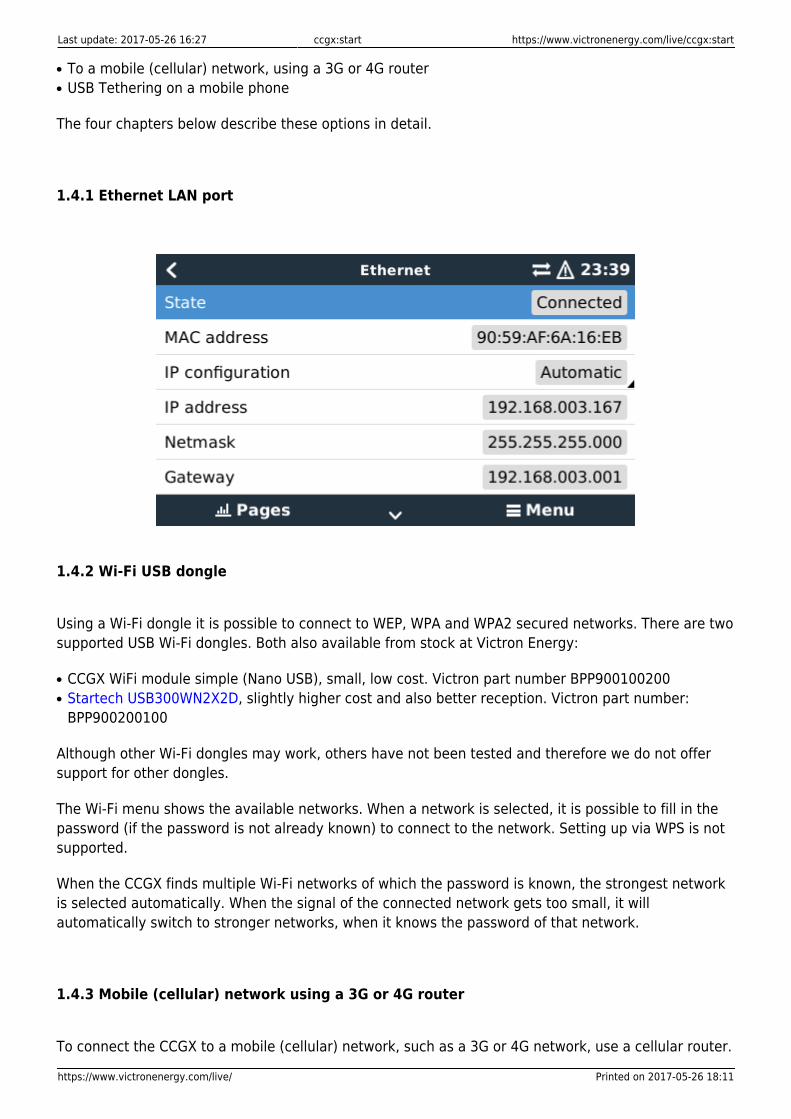
1.4.1 Ethernet LAN port
1.4.2 Wi-Fi USB dongle
Using a Wi-Fi dongle it is possible to connect to WEP, WPA and WPA2 secured networks. There are twosupported USB Wi-Fi dongles. Both also available from stock at Victron Energy:
CCGX WiFi module simple (Nano USB), small, low cost. Victron part number BPP900100200●
Startech USB300WN2X2D, slightly higher cost and also better reception. Victron part number:●
BPP900200100
Although other Wi-Fi dongles may work, others have not been tested and therefore we do not offersupport for other dongles.
The Wi-Fi menu shows the available networks. When a network is selected, it is possible to fill in thepassword (if the password is not already known) to connect to the network. Setting up via WPS is notsupported.
When the CCGX finds multiple Wi-Fi networks of which the password is known, the strongest networkis selected automatically. When the signal of the connected network gets too small, it willautomatically switch to stronger networks, when it knows the password of that network.
1.4.3 Mobile (cellular) network using a 3G or 4G router
To connect the CCGX to a mobile (cellular) network, such as a 3G or 4G network, use a cellular router.
2017-05-26 18:11 9/22 Color Control GX manual
Victron Energy - https://www.victronenergy.com/live/
Connect the CCGX to that router with either a LAN cable or the router's Wi-Fi network.
Make sure to use router that is designed for unattended setups. Do not use low cost consumer-graderouters, intended for business or leisure travel. The more expensive professional router will quicklypay for itself. And won't require you to travel up and down to only find out that it needs a power cycle.Examples of such professional routers are the H685 4G LTE from Proroute, as well as the Industrial 4Grouter range from Pepwave.
More information in this blogpost.
Note that the CCGX does not support USB 3G/4G dongles.
1.4.4 USB tethering on a mobile phone
Note that this is in the category: nice that it works, as long as it works, but don't rely on it. Enable USBtethering on your phone (See Google on how to do that for your particular make, model and operatingsystem). It has been reported to work on:
Samsung Galaxy S4●
And reported not to work on:
iPhone 5s with iOS 8.1.1●
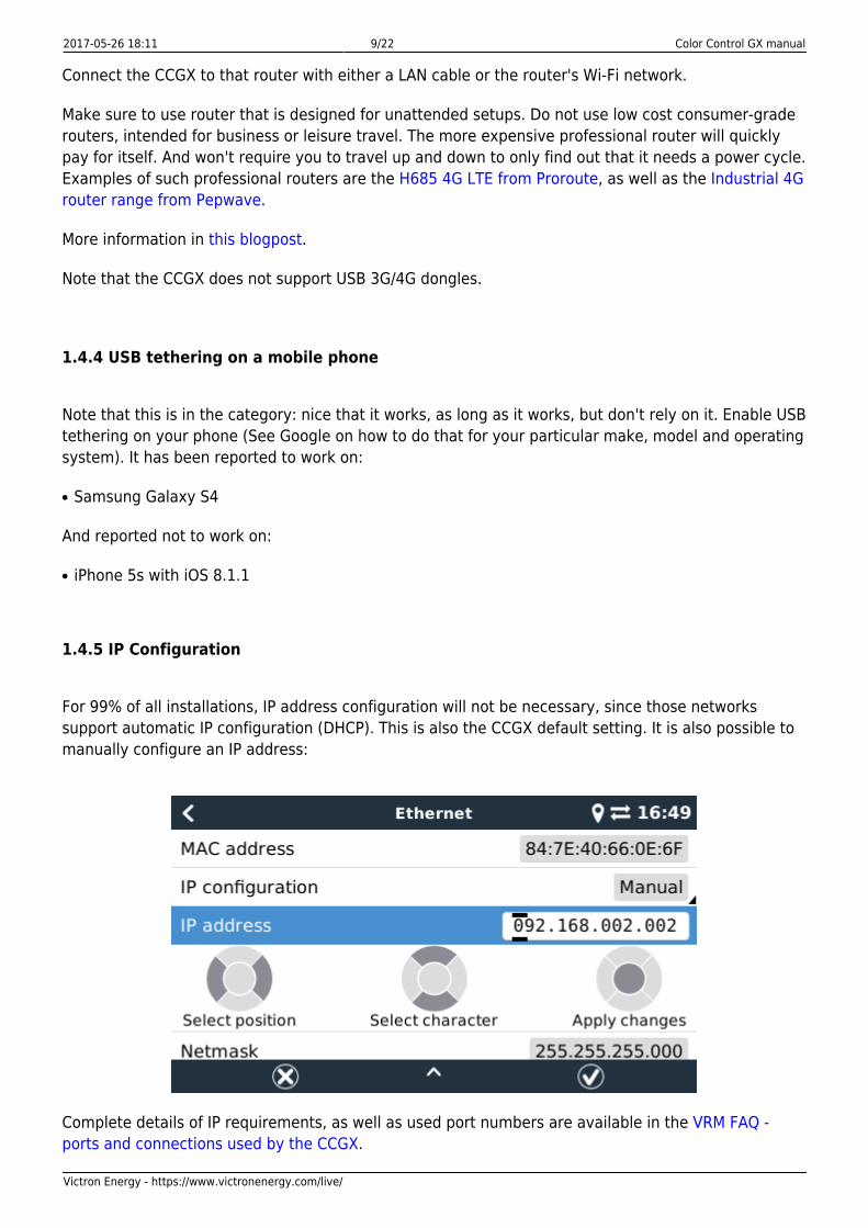
1.4.5 IP Configuration
For 99% of all installations, IP address configuration will not be necessary, since those networkssupport automatic IP configuration (DHCP). This is also the CCGX default setting. It is also possible tomanually configure an IP address:
Complete details of IP requirements, as well as used port numbers are available in the VRM FAQ -ports and connections used by the CCGX.
Last update: 2017-05-26 16:27 ccgx:start https://www.victronenergy.com/live/ccgx:start
https://www.victronenergy.com/live/ Printed on 2017-05-26 18:11
1.4.6 Connecting both Ethernet and Wi-Fi (failover)
It is possible to connect the CCGX to both Ethernet and Wi-Fi. In this case, the CCGX will try todetermine which interface provides an active internet connection and then use that interface. Whenboth have an active internet connection, the Ethernet connection is used. The CCGX will automaticallycheck again for active internet connections when something changes on the interfaces.
1.4.7 Minimize internet traffic
In situations where internet traffic is expensive, for example a satellite uplink or with roamingGSM/cellular charges, you may want to minimize the internet traffic. The steps to take are:
Disable auto-update●
Do not enable remote support●
Possibly set the Logging interval to a very low frequency. Note that state changes (charging →●
inverting, or bulk→float) and also alarms will cause extra messages to be sent
To find out how much traffic you need, in order to purchase the right plan, the best way is really to letthe system run for a couple of days and monitor the internet RX and TX counters in your 3G or 4Grouter. Or even better, some mobile companies will report the data used via a website. Besides theabove three points, the amount of data used is also very dependent on the system:
More products connected will generate more data●
A state change (from inverter to charger for example) will trigger a data transmission, so a system●
with very frequent state changes will also tend to generate more data. This is especially true incertain Hub-1 and Hub-2 systems.
Note that CCGX versions prior to v1.18 would still check for software updates daily, even whenauto-update was be switched off. This has been changed in v1.18: disabling auto-update also disablesthe check, saving a lot of data.
We recommend to set the mobile plan up in such a way that there are no surprises. Make sure to puta cap on data usage, or use pre-paid plans.
One customer has come up with an even more advanced plan. They had to, since they are usingglobal roaming SIM Cards that start at EUR 0,20 cents per megabyte, but in the more interestingcountries to visit they go up to several Euros per megabyte. His solution is using a VPN and hemodified the IP routing table to route ALL traffic to and from the CCGX via his VPN. Using a firewall atthe VPN server allows him to control traffic according to time, connection type, place and destinations.Note that this is really out of scope for Victron to support you with. If you need this, look for a Linuxand networking expert that can help you.
1.4.8 More information about setting up an internet connection and VRM
Setting up a VRM account●
2017-05-26 18:11 11/22 Color Control GX manual
Victron Energy - https://www.victronenergy.com/live/
Trouble shooting connectivity between the CCGX and the VRM Portal●
VRM Portal alarms and monitoring●
VRM Portal - Frequently asked questions●
1.5 Connecting a USB GPS
Use a GPS to track remote vehicles or boats and optionally get an alarm when they leave adesignated area (geofencing). It is also possible to download a gps-tracks.kml file which can beopened with Navlink and Google Earth for example.
Use an off-the-shelf USB-GPS, Victron does not sell them. Plug it into one of the two USB sockets. Aftera while, which can take up to a few minutes, the CCGX will automatically recognize the GPS. Thelocation is automatically sent to the VRM online portal, where it is used to show the position on themap.
The CCGX supports GPS modules that work with the NMEA0183 command-set, as almost all do. Both4800 and 38400 baud. Tested for compatibility are:
Globalsat BU353-W SiRF STAR III 4800 baud●
Globalsat ND100 SiRF STAR III 38400 baud●
Globalsat BU353S4 SiRF STAR IV 4800 baud●
Globalsat MR350 + BR305US SiRF STAR III 4800 baud●
2 Configuration
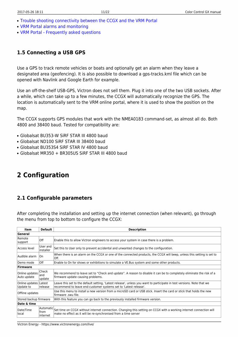
2.1 Configurable parameters
After completing the installation and setting up the internet connection (when relevant), go throughthe menu from top to bottom to configure the CCGX:
Item Default DescriptionGeneralRemotesupport Off Enable this to allow Victron engineers to access your system in case there is a problem.
Access level User andinstaller Set this to User only to prevent accidental and unwanted changes to the configuration.
Audible alarm On When there is an alarm on the CCGX or one of the connected products, the CCGX will beep, unless this setting is set toOff.
Demo mode Off Enable to On for shows or exhibitions to simulate a VE.Bus system and some other products.Firmware
Online updates:Auto update
Checkandupdate
We recommend to leave set to “Check and update”. A reason to disable it can be to completely eliminate the risk of afirmware update causing problems.
Online updates:Update to
Latestrelease
Leave this set to the default setting, 'Latest release', unless you want to participate in test versions. Note that werecommend to leave end-customer systems set to 'Latest release'.
Offline updates Use this menu to install a new version from a microSD card or USB stick. Insert the card or stick that holds the newfirmware .swu file.
Stored backup firmware With this feature you can go back to the previously installed firmware version.Date & time
Date/Timelocal
Automaticfrominternet
Set time on CCGX without internet connection. Changing this setting on CCGX with a working internet connection willmake no effect as it will be re-synchronised from a time server
Last update: 2017-05-26 16:27 ccgx:start https://www.victronenergy.com/live/ccgx:start
https://www.victronenergy.com/live/ Printed on 2017-05-26 18:11
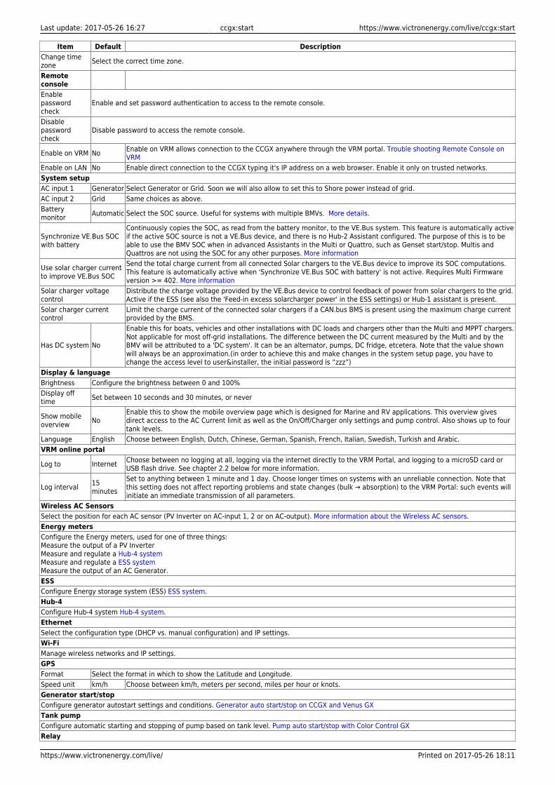
Item Default DescriptionChange timezone Select the correct time zone.
RemoteconsoleEnablepasswordcheck
Enable and set password authentication to access to the remote console.
Disablepasswordcheck
Disable password to access the remote console.
Enable on VRM No Enable on VRM allows connection to the CCGX anywhere through the VRM portal. Trouble shooting Remote Console onVRM
Enable on LAN No Enable direct connection to the CCGX typing it's IP address on a web browser. Enable it only on trusted networks.System setupAC input 1 Generator Select Generator or Grid. Soon we will also allow to set this to Shore power instead of grid.AC input 2 Grid Same choices as above.Batterymonitor Automatic Select the SOC source. Useful for systems with multiple BMVs. More details.
Synchronize VE.Bus SOCwith battery
Continuously copies the SOC, as read from the battery monitor, to the VE.Bus system. This feature is automatically activeif the active SOC source is not a VE.Bus device, and there is no Hub-2 Assistant configured. The purpose of this is to beable to use the BMV SOC when in advanced Assistants in the Multi or Quattro, such as Genset start/stop. Multis andQuattros are not using the SOC for any other purposes. More information
Use solar charger currentto improve VE.Bus SOC
Send the total charge current from all connected Solar chargers to the VE.Bus device to improve its SOC computations.This feature is automatically active when 'Synchronize VE.Bus SOC with battery' is not active. Requires Multi Firmwareversion >= 402. More information
Solar charger voltagecontrol
Distribute the charge voltage provided by the VE.Bus device to control feedback of power from solar chargers to the grid.Active if the ESS (see also the 'Feed-in excess solarcharger power' in the ESS settings) or Hub-1 assistant is present.
Solar charger currentcontrol
Limit the charge current of the connected solar chargers if a CAN.bus BMS is present using the maximum charge currentprovided by the BMS.
Has DC system No
Enable this for boats, vehicles and other installations with DC loads and chargers other than the Multi and MPPT chargers.Not applicable for most off-grid installations. The difference between the DC current measured by the Multi and by theBMV will be attributed to a 'DC system'. It can be an alternator, pumps, DC fridge, etcetera. Note that the value shownwill always be an approximation.(in order to achieve this and make changes in the system setup page, you have tochange the access level to user&installer, the initial password is “zzz”)
Display & languageBrightness Configure the brightness between 0 and 100%Display offtime Set between 10 seconds and 30 minutes, or never
Show mobileoverview No
Enable this to show the mobile overview page which is designed for Marine and RV applications. This overview givesdirect access to the AC Current limit as well as the On/Off/Charger only settings and pump control. Also shows up to fourtank levels.
Language English Choose between English, Dutch, Chinese, German, Spanish, French, Italian, Swedish, Turkish and Arabic.VRM online portal
Log to Internet Choose between no logging at all, logging via the internet directly to the VRM Portal, and logging to a microSD card orUSB flash drive. See chapter 2.2 below for more information.
Log interval 15minutes
Set to anything between 1 minute and 1 day. Choose longer times on systems with an unreliable connection. Note thatthis setting does not affect reporting problems and state changes (bulk → absorption) to the VRM Portal: such events willinitiate an immediate transmission of all parameters.
Wireless AC SensorsSelect the position for each AC sensor (PV Inverter on AC-input 1, 2 or on AC-output). More information about the Wireless AC sensors.Energy metersConfigure the Energy meters, used for one of three things:Measure the output of a PV InverterMeasure and regulate a Hub-4 systemMeasure and regulate a ESS systemMeasure the output of an AC Generator.ESSConfigure Energy storage system (ESS) ESS system.Hub-4Configure Hub-4 system Hub-4 system.EthernetSelect the configuration type (DHCP vs. manual configuration) and IP settings.Wi-FiManage wireless networks and IP settings.GPSFormat Select the format in which to show the Latitude and Longitude.Speed unit km/h Choose between km/h, meters per second, miles per hour or knots.Generator start/stopConfigure generator autostart settings and conditions. Generator auto start/stop on CCGX and Venus GXTank pumpConfigure automatic starting and stopping of pump based on tank level. Pump auto start/stop with Color Control GXRelay
2017-05-26 18:11 13/22 Color Control GX manual
Victron Energy - https://www.victronenergy.com/live/
Item Default Description
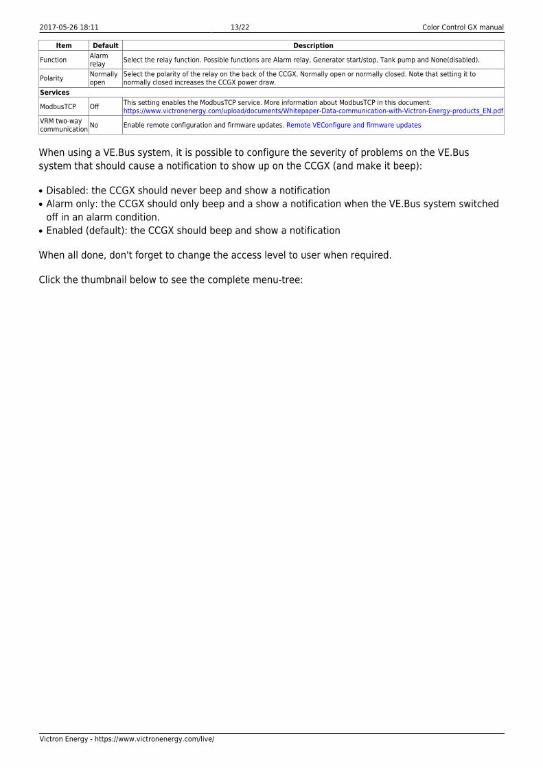
Function Alarmrelay Select the relay function. Possible functions are Alarm relay, Generator start/stop, Tank pump and None(disabled).
Polarity Normallyopen
Select the polarity of the relay on the back of the CCGX. Normally open or normally closed. Note that setting it tonormally closed increases the CCGX power draw.
Services
ModbusTCP Off This setting enables the ModbusTCP service. More information about ModbusTCP in this document:https://www.victronenergy.com/upload/documents/Whitepaper-Data-communication-with-Victron-Energy-products_EN.pdf
VRM two-waycommunication No Enable remote configuration and firmware updates. Remote VEConfigure and firmware updates
When using a VE.Bus system, it is possible to configure the severity of problems on the VE.Bussystem that should cause a notification to show up on the CCGX (and make it beep):
Disabled: the CCGX should never beep and show a notification●
Alarm only: the CCGX should only beep and a show a notification when the VE.Bus system switched●
off in an alarm condition.Enabled (default): the CCGX should beep and show a notification●
When all done, don't forget to change the access level to user when required.
Click the thumbnail below to see the complete menu-tree:
Last update: 2017-05-26 16:27 ccgx:start https://www.victronenergy.com/live/ccgx:start
https://www.victronenergy.com/live/ Printed on 2017-05-26 18:11
2.2 Logging data for the VRM portal
The CCGX can be used in combination with the Victron Remote Management (VRM) portal: The CCGXmonitors all products connected to it and the VRM portal makes the statistics easily accessible.
Since version 1.40, dealing with an absent or intermittent internet connection has changed. Data issent out via the Internet if it's available, and will fall back to non-volatile storage when there is a
2017-05-26 18:11 15/22 Color Control GX manual
Victron Energy - https://www.victronenergy.com/live/
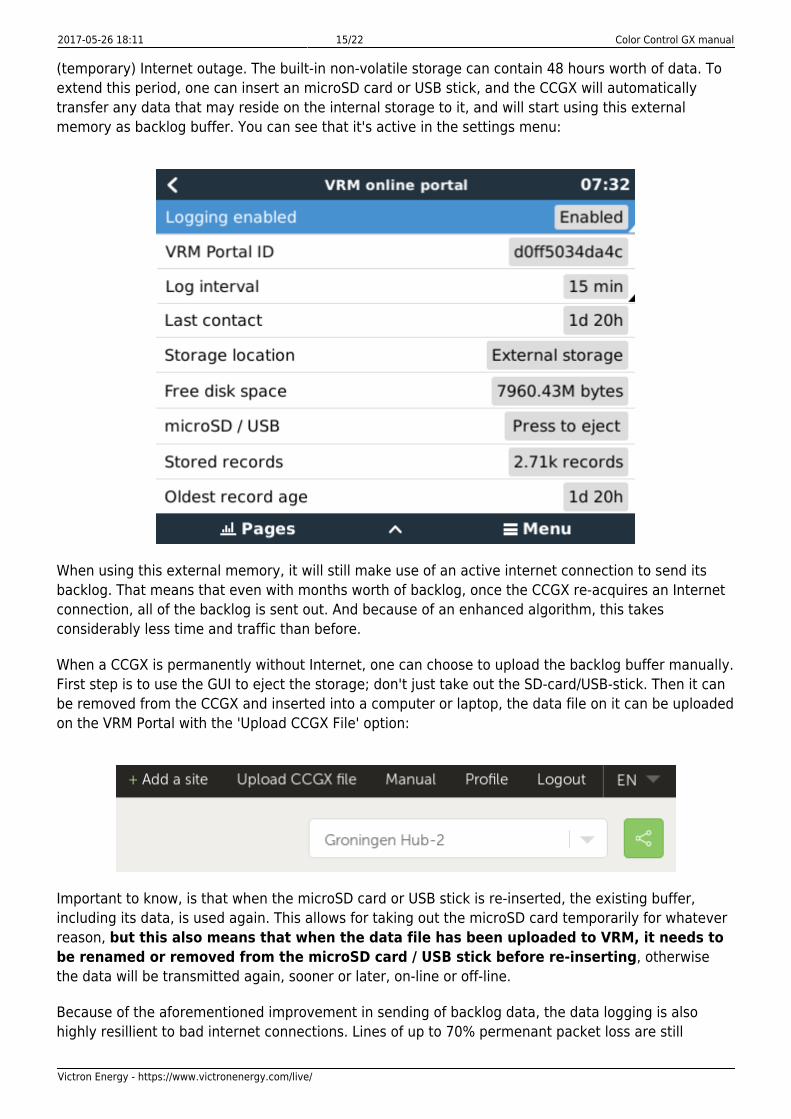
(temporary) Internet outage. The built-in non-volatile storage can contain 48 hours worth of data. Toextend this period, one can insert an microSD card or USB stick, and the CCGX will automaticallytransfer any data that may reside on the internal storage to it, and will start using this externalmemory as backlog buffer. You can see that it's active in the settings menu:
When using this external memory, it will still make use of an active internet connection to send itsbacklog. That means that even with months worth of backlog, once the CCGX re-acquires an Internetconnection, all of the backlog is sent out. And because of an enhanced algorithm, this takesconsiderably less time and traffic than before.
When a CCGX is permanently without Internet, one can choose to upload the backlog buffer manually.First step is to use the GUI to eject the storage; don't just take out the SD-card/USB-stick. Then it canbe removed from the CCGX and inserted into a computer or laptop, the data file on it can be uploadedon the VRM Portal with the 'Upload CCGX File' option:
Important to know, is that when the microSD card or USB stick is re-inserted, the existing buffer,including its data, is used again. This allows for taking out the microSD card temporarily for whateverreason, but this also means that when the data file has been uploaded to VRM, it needs tobe renamed or removed from the microSD card / USB stick before re-inserting, otherwisethe data will be transmitted again, sooner or later, on-line or off-line.
Because of the aforementioned improvement in sending of backlog data, the data logging is alsohighly resillient to bad internet connections. Lines of up to 70% permenant packet loss are still
Last update: 2017-05-26 16:27 ccgx:start https://www.victronenergy.com/live/ccgx:start
https://www.victronenergy.com/live/ Printed on 2017-05-26 18:11
sufficient to get the data out, albeit a bit delayed sometimes.
With a log interval of once per minute, the required storage space roughly amounts to about 25 MBper month, depending on the amount of products that are connected. So with a 1 GB microSD card,you can store about 3 years of backlog. In other words, any microSD card or USB stick should besufficient to store the 6 months of data VRM retains.
Should the storage space run out, no more data is logged. This is due to the nature of Sqlite files.Removing data from the Sqlite database doesn't free up usable disk space, and because of internalfragmentation, it's also not guaranteed that there is enough free internal space.
If both a microSD card and a USB flash drive are connected to the CCGX, then data is logged to theone that was inserted first. If one is removed, the CCGX will not try to write to the other, but willcreate an internal backlog buffer until a new storage medium is inserted and then use that storagemedium.
The microSD card or USB flash drive must be formatted as FAT12, FAT16 or FAT32 file system and notexFAT or NTFS. SD and SDHC type microSD cards which are less than or equal to 32 GB are soldcontaining FAT12, FAT16 or FAT32. This means they can be used without a problem, unless they aresubsequently formatted to a different and non acceptable file system. SDXC type microSD cardswhich are mostly greater than 32 are sold with exFAT, and therefore cannot be used with the CCGXwithout reformatting and possibly repartitioning.
2.3 Using the Multi and Quattro input current limiter setting
Interaction with the Overruled by remote setting in VEConfigure
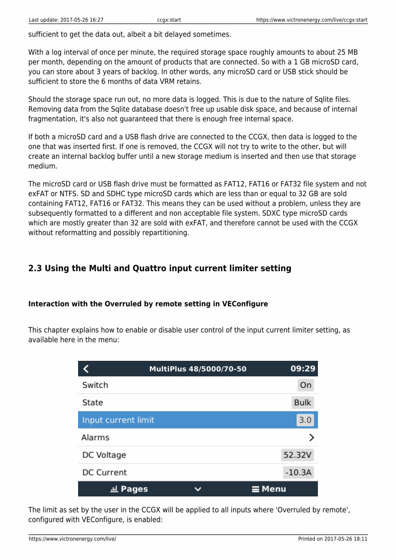
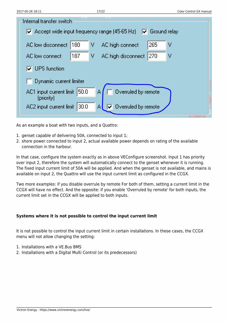
This chapter explains how to enable or disable user control of the input current limiter setting, asavailable here in the menu:
The limit as set by the user in the CCGX will be applied to all inputs where 'Overruled by remote',configured with VEConfigure, is enabled:
2017-05-26 18:11 17/22 Color Control GX manual
Victron Energy - https://www.victronenergy.com/live/
As an example a boat with two inputs, and a Quattro:
genset capable of delivering 50A, connected to input 1;1.shore power connected to input 2, actual available power depends on rating of the available2.connection in the harbour.
In that case, configure the system exactly as in above VEConfigure screenshot. Input 1 has priorityover input 2, therefore the system will automatically connect to the genset whenever it is running.The fixed input current limit of 50A will be applied. And when the genset is not available, and mains isavailable on input 2, the Quattro will use the input current limit as configured in the CCGX.
Two more examples: if you disable overrule by remote For both of them, setting a current limit in theCCGX will have no effect. And the opposite: if you enable 'Overruled by remote' for both inputs, thecurrent limit set in the CCGX will be applied to both inputs.
Systems where it is not possible to control the input current limit
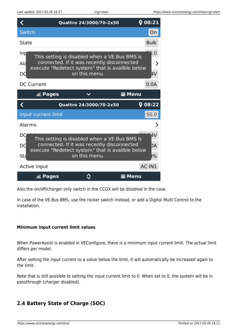
It is not possible to control the input current limit in certain installations. In these cases, the CCGXmenu will not allow changing the setting:
Installations with a VE.Bus BMS1.Installations with a Digital Multi Control (or its predecessors)2.
Last update: 2017-05-26 16:27 ccgx:start https://www.victronenergy.com/live/ccgx:start
https://www.victronenergy.com/live/ Printed on 2017-05-26 18:11
Also the on/off/charger only switch in the CCGX will be disabled in the case.
In case of the VE.Bus BMS, use the rocker switch instead, or add a Digital Multi Control to theinstallation.
Minimum input current limit values
When PowerAssist is enabled in VEConfigure, there is a minimum input current limit. The actual limitdiffers per model.
After setting the input current to a value below the limit, it will automatically be increased again tothe limit.
Note that is still possible to setting the input current limit to 0. When set to 0, the system will be inpassthrough (charger disabled).
2.4 Battery State of Charge (SOC)
2017-05-26 18:11 19/22 Color Control GX manual
Victron Energy - https://www.victronenergy.com/live/
2.4.1 System Components
There are three products types that calculate State Of Charge (SOC). The CCGX itself does notcalculate SOC, it only retrieves it from the connected devices.
The three products that calculate SOC are:
dedicated Battery Monitors, such as the BMVs, the Lynx Shunt, or the Lynx Ion BMS1.Multi and Quattro inverter/chargers2.Batteries with built-in battery monitor and a (mostly CAN bus) connection to the CCGX.3.
A dedicated battery monitor such as the mentioned BMV and Lynx products, are only required forcertain systems:
Battery and Multi or Quattro (a typical backup system)
No battery monitor is required: the Multi or Quattro is the only product connected to the battery andhas full control over all charge and discharge currents.
Configuration:
Enable and configure the Battery Monitor in VEConfigure.1.In the CCGX, in Settings → System setup, verify the selected Battery Monitor. It should be set to the2.Multi or Quattro.
Battery with Multi or Quattro and MPPT Solar Chargers
No battery monitor is required, as long as all MPPT Solar Chargers are Victron and connected to theCCGX. The CCGX will continuously read the actual charge current from all solar chargers, and sendthe total to the Multi (or Quattro) which then uses that information in its SOC calculations.
Configuration:
Enable and configure the Battery Monitor in VEConfigure.1.In the CCGX, in Settings → System setup, verify the selected Battery Monitor. It should be the Multi2.or Quattro.In the same menu, verify that the 'Use solar charger current to improve VE.Bus SOC' is enabled.3.Note that this is not a setting, it just an indicator of an automatic process.
Note that this feature requires recent firmware versions in both the Multis or Quattros (402 minimum),and the CCGX (v2.06 minimum).
An EasySolar with CCGX built-in
See previous.
Batteries with a built-in battery monitor
In case the system includes a battery with a built-in battery monitor and SOC calculation, such asmany of the batteries listed here, a dedicated battery monitor is not required.
Configuration:
Last update: 2017-05-26 16:27 ccgx:start https://www.victronenergy.com/live/ccgx:start
https://www.victronenergy.com/live/ Printed on 2017-05-26 18:11
Connect the battery communications cable to the CCGX according to the instructions.1.In the CCGX, in Settings → System setup, verify that the selected Battery Monitor is the battery.2.
Note that the Battery Monitor setting in VEConfigure3 is irrelevant. For systems like this, changing thissetting has no effect to the charge or any other mechanisms in this type of system.
Other system types
When there are more chargers, or loads, connected to the battery than just the Multi or MPPT SolarChargers, a dedicated Battery Monitor will be required. Examples are:
House loads in Marine or Vehicle system.●
PWM Solar Chargers●
AC chargers, such as Skylla-is, Phoenix chargers, non Victron chargers, etc.●
Alternators●
DC-DC chargers●
Wind turbines●
Hydro turbines●
Configuration:
Configure all BMV parameters (see BMV documentation)1.In the CCGX, in Settings → System setup, verify the selected Battery Monitor. It should be the BMV2.Battery Monitor.
Note that the Battery Monitor setting in VEConfigure3 is irrelevant. For systems like this, changing thissetting has no effect to the charge- or any other mechanisms in this type of system.
Notes
Note that this is about showing an accurate state of charge to the user, not about the system●
working well. The SOC percentage is not used for normal battery charging. an example there it isrequired for system function is when a genset needs to be started and stopped automatically basedon battery SOC.For hub-2 installations we recommend to not add a BMV to the system. Since it will only confuse the●
user of the system as there are then two different SOCs being calculated and shown to the user.
More information:
VRM Portal FAQ - difference between BMV SOC and VE.Bus SOC●
CCGX Manual - configurable parameters. See Battery Monitor selection and Has DC System.●
2.4.2 Selecting SOC source
(Settings → System Setup → Battery monitor)
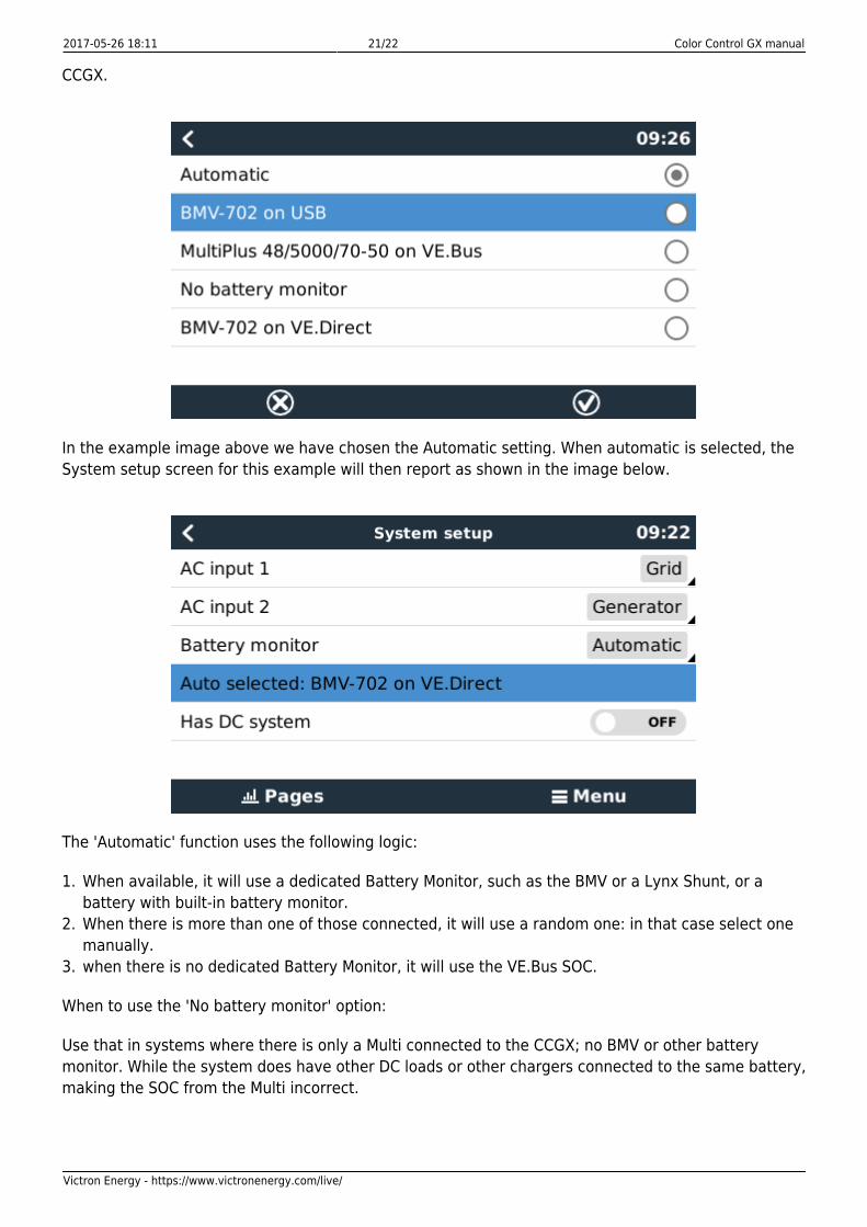
In the image below you can see a range of selectable choices for the SOC values that will be shown inthe main Overview screen. Choose the source you want to see on the main Overview screen of your
2017-05-26 18:11 21/22 Color Control GX manual
Victron Energy - https://www.victronenergy.com/live/
CCGX.
In the example image above we have chosen the Automatic setting. When automatic is selected, theSystem setup screen for this example will then report as shown in the image below.
The 'Automatic' function uses the following logic:
When available, it will use a dedicated Battery Monitor, such as the BMV or a Lynx Shunt, or a1.battery with built-in battery monitor.When there is more than one of those connected, it will use a random one: in that case select one2.manually.when there is no dedicated Battery Monitor, it will use the VE.Bus SOC.3.
When to use the 'No battery monitor' option:
Use that in systems where there is only a Multi connected to the CCGX; no BMV or other batterymonitor. While the system does have other DC loads or other chargers connected to the same battery,making the SOC from the Multi incorrect.
Last update: 2017-05-26 16:27 ccgx:start https://www.victronenergy.com/live/ccgx:start
https://www.victronenergy.com/live/ Printed on 2017-05-26 18:11
3 More information resources
CCGX Genset start/stop●
CCGX Frequently asked questions●
CCGX Firmware upgrade to v2.00 or later●
CCGX Manually updating firmware●
CCGX Remote VEConfigure and remote firmware updates●
CCGX Datasheet●
VRM Portal●
VRM Portal - trouble shooting Remote Console●
Open source●
DISQUS CommentsView the discussion thread.
From:https://www.victronenergy.com/live/ - Victron Energy
Permanent link:https://www.victronenergy.com/live/ccgx:start
Last update: 2017-05-26 16:27