Embed Size (px)
Citation preview

COLOR GPS PLOTTER GP-3300COLOR VIDEO PLOTTER GD-3300
Your Local Agent/DealerYour Local Agent/Dealer
9-52 Ashihara-cho,9-52 Ashihara-cho,Nishinomiya, JapanNishinomiya, Japan
Telephone :Telephone : 0798-65-21110798-65-2111Telefax :Telefax : 0798-65-42000798-65-4200
FIRST EDITION :FIRST EDITION : AUG.AUG. 19981998Printed in JapanPrinted in JapanAll rights reserved.All rights reserved.D :D : JUL.JUL. 22,200222,2002
PUB.No.PUB.No. IME-43920-DIME-43920-D*00080834700**00080834700**00080834700**00080834700*(( TENITENI )) GD/GP-3300GD/GP-3300
* 0 0 0 8 0 8 3 4 7 0 0 ** 0 0 0 8 0 8 3 4 7 0 0 *
*IME43920D00**IME43920D00**IME43920D00**IME43920D00*
* I M E 4 3 9 2 0 D 0 0 ** I M E 4 3 9 2 0 D 0 0 *
iiiiiiiiiiiii i
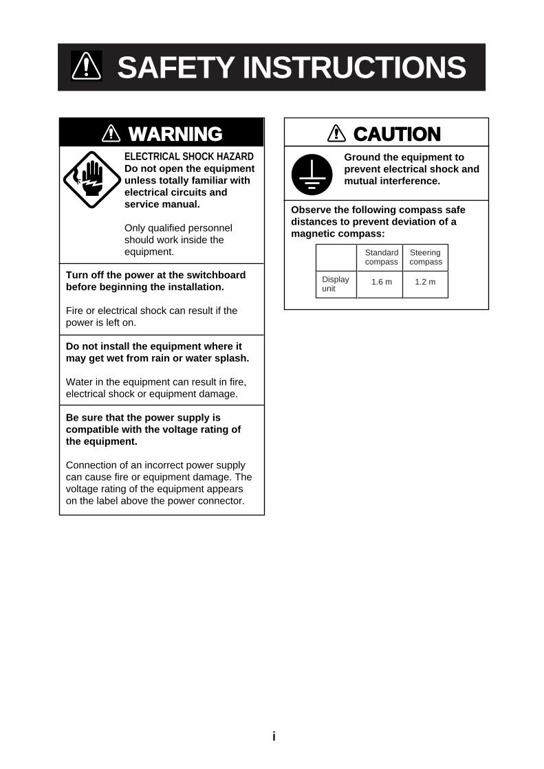
SAFETY INSTRUCTIONS
WARNING
Turn off the power at the switchboardbefore beginning the installation.
Fire or electrical shock can result if thepower is left on.
Do not install the equipment where itmay get wet from rain or water splash.
Water in the equipment can result in fire,electrical shock or equipment damage.
Be sure that the power supply iscompatible with the voltage rating ofthe equipment.
Connection of an incorrect power supplycan cause fire or equipment damage. Thevoltage rating of the equipment appearson the label above the power connector.
ELECTRICAL SHOCK HAZARDDo not open the equipmentunless totally familiar withelectrical circuits andservice manual.
Only qualified personnelshould work inside theequipment.
CAUTION
Observe the following compass safedistances to prevent deviation of amagnetic compass:
Ground the equipment toprevent electrical shock andmutual interference.
Displayunit
Standard Steeringcompass compass
1.6 m 1.2 m

1
TABLE OF CONTENTS
SYSTEM CONFIGURATION .................................................................................................2
EQUIPMENT LISTS ...............................................................................................................3
DISPLAY UNIT .......................................................................................................................5
ANTENNA UNIT (GP-3300) ...................................................................................................7
WIRING ..................................................................................................................................9
DGPS BEACON RECEIVER GR-80 CONNECTION (GP-3300 only) ................................. 10
INITIAL SETTINGS .............................................................................................................. 11
JUMPER WIRE, DIP SWITCH SETTINGS ON GDC BOARD.............................................15
I/O DATA DESCRIPTION .....................................................................................................18

2
SYSTEM CONFIGURATION
GPS PLOTTER
ON
POWER
OFF
9
6
32
5
87
4
1
0
BRILLECONO
ENT
CENTER
SELECT
MARKCOLOR
FR/TO WPT ROUTE ALARM
TRACKCOLOR
PLOTINTVL
CHART
CLR
EVENT
PLOT
MODEVIDEOPILOT
NAVDATA MANU
ZOOMIN
ZOOMOUT
CURSORON/OFF
GPS ANTENNA UNITGPA-017S(For GP-3300)
Navigator (for GD-3300)Video SounderRadarAutopilotEvent Switch
Differential GPSReceiver GR-80*(GP-3300 only)
: Option: Connectable external equipment
* Cannot be connected to GD-3300.
DISPLAY UNIT GP-3300-E/GD-3300-E
SHIP’S MAINS10.8 - 31.2 VDC
RectifierPR-62
100/110/220/230 VAC,1φ, 50/60 Hz
Figure 1 System configuration
3
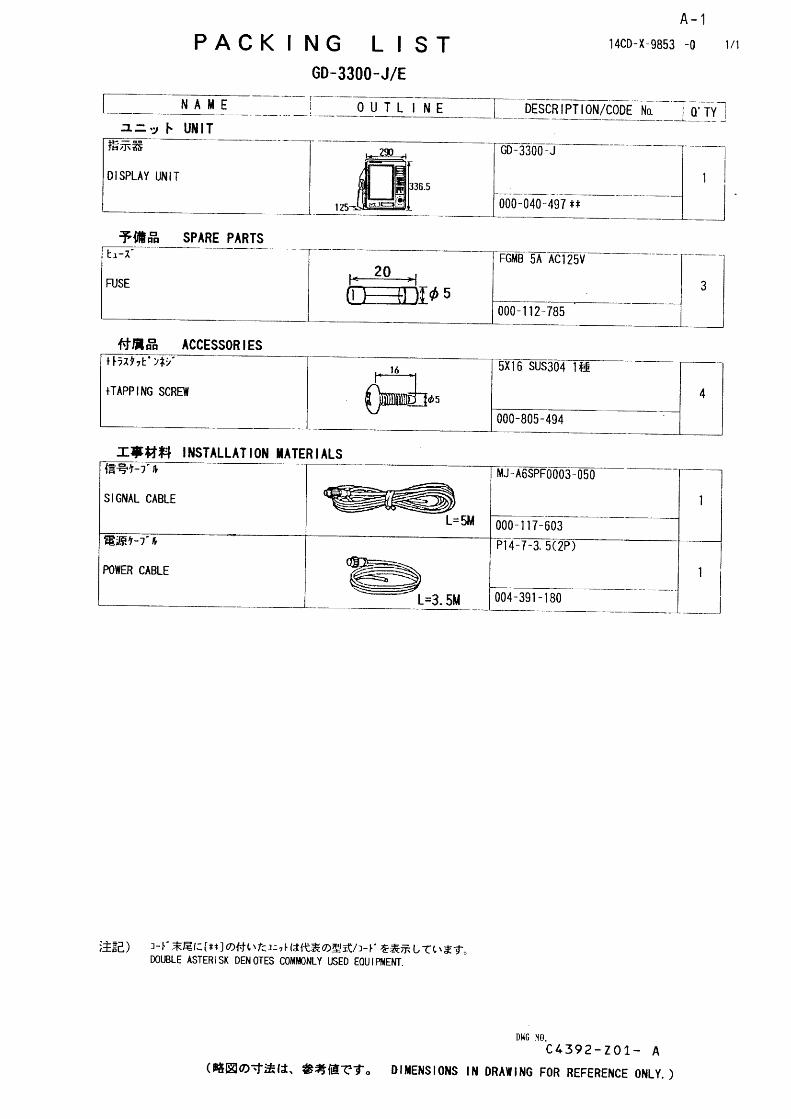
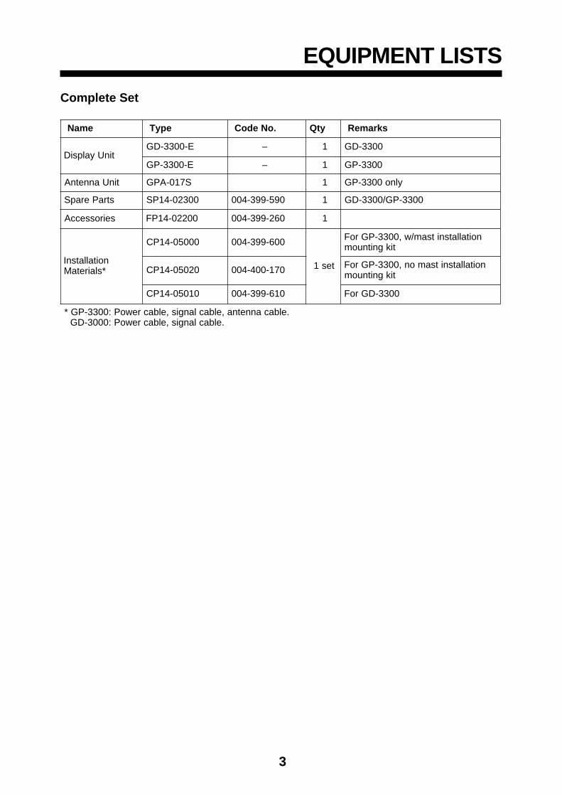
EQUIPMENT LISTS
Complete Set
emaN epyT .oNedoC ytQ skrameR
tinUyalpsiDE-0033-DG – 1 0033-DG
E-0033-PG – 1 0033-PG
tinUannetnA S710-APG 1 ylno0033-PG
straPerapS 00320-41PS 095-993-400 1 0033-PG/0033-DG
seirosseccA 00220-41PF 062-993-400 1
noitallatsnI*slairetaM
00050-41PC 006-993-400
tes1
noitallatsnitsam/w,0033-PGroFtikgnitnuom
02050-41PC 071-004-400 noitallatsnitsamon,0033-PGroFtikgnitnuom
01050-41PC 016-993-400 0033-DGroF
.elbacannetna,elbaclangis,elbacrewoP:0033-PG*.elbaclangis,elbacrewoP:0003-DG

4
Optional Equipment
emaN epyT edoC ytQ skrameR
reifitceR
5.1/5YG5.226-RP5#TN 584-310-000
1
CAV011
5.1/5YG5.226-RP5#TN 784-310-000 CAV032
5#TN2/7G5.226-RP 984-310-000 CAV011
5#TN2/7G5.226-RP 194-310-000 CAV032
draCMAR)dracyromeM(
100-C652MAR00 070-123-4001
BK652
200-C215MAR00 032-223-400 BK215
gnitnuoMtsaMtiKnoitallatsnI 11110-02PC 087-563-400 1
.yssAelbaCannetnA 00440-41PC 070-373-400 1 annetnarof,m03noisnetxeelbac
.yssAelbaCannetnA 01440-41PC 080-373-400 1 annetnarof,m05noisnetxeelbac
gnitnuoMelgnAthgiResaB 033AQ-31.oN 932-308-000 1
annetnagnitnuomroF0033-PGfotinuesaBgnitnuoMelgna-L 013AQ-31.oN 042-308-000 1
esaBgnitnuoMliardnaH 0615CR-31.oN 411-608-000 1
.yssAelbaC
001-7000FPS6A-JM 732-521-000
1
,m01,tolipotuaroFrotcennocP6/w,thgiarts
sdnehtobta
001-2100FPS6A-JM 718-331-000
ohce,rotagivanroF,ssorc,m01,rednuoshtobtarotcennocP6/w
sdne
050-2100FPS6A-JM 424-431-000
ohcerorotagivanroF,ssorc,m5,rednuos
htobtarotcennocP6/wsdne
050-1100FPS6A-JM 442-231-000 ,radarroF ,ssorc,m5rotcennocP4-P6/w
001-1100FPS6A-JM 633-231-000 ,radarroF -P6/w,m01rotcennocP4
050-3000FPS7A-JM 10-037-631-000,SPGDroF,0033-PG
tarotcennocP7/w,m5sdnehtob
elbaClangiS 050-3000FPS6A-JM 306-711-000 1
ohce,rotagivaN,rednuos tolipotua ,m5,
htobtarotcennocP6/wsdne

5
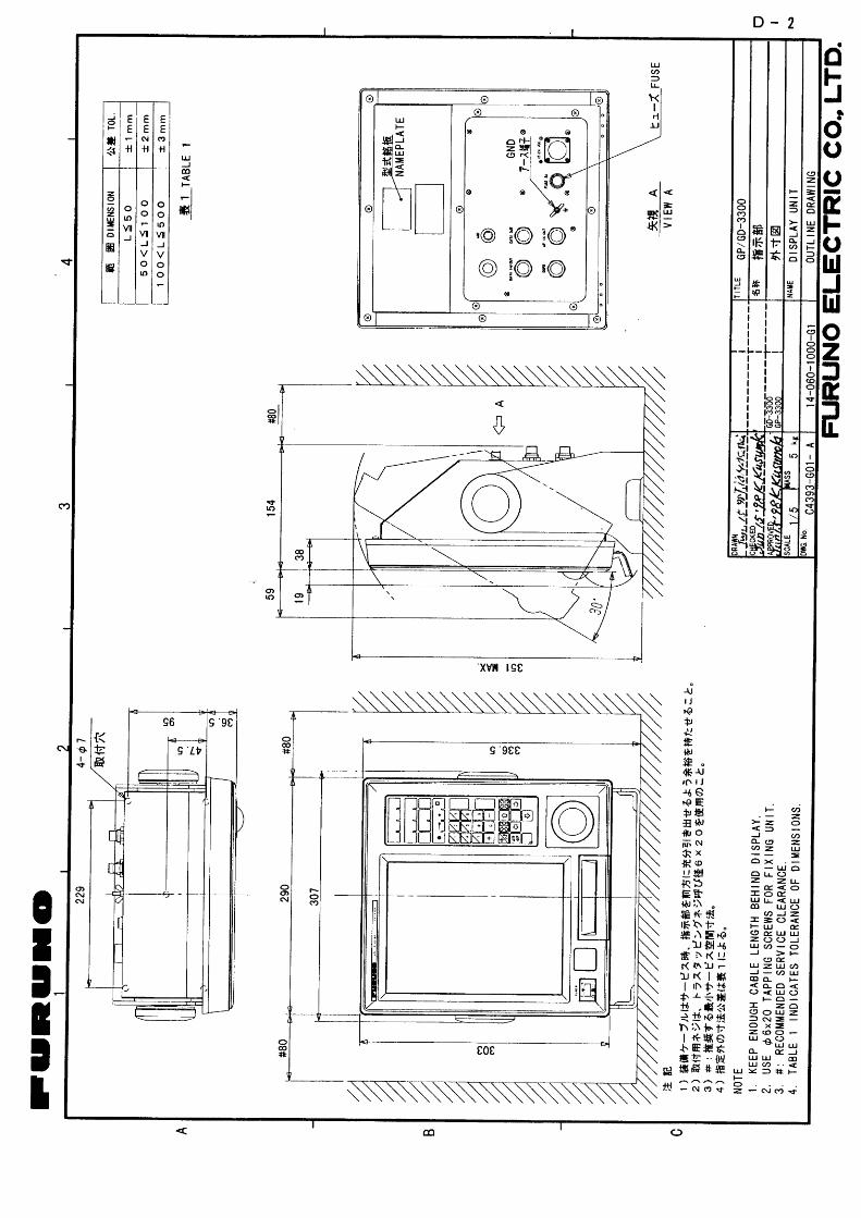
DISPLAY UNIT
Mounting Considerations
The display unit can be installed on a tabletop or on the over-head. When selecting a mounting location keep in mind thefollowing points.
• Install the unit where it can be easily viewed and operated.
• Keep the unit out of direct sunlight.
• Locate the unit well away from a place exposed to rain orwater splash.
• Locate the unit away from air-conditioner or heater.
• Select a location where vibration is minimal.
• Be sure the mounting area is well ventilated.
• Select a mounting location of moderate temperature and lowhumidity.
• Locate the unit well away from equipment which generate amagnetic field.
• Be sure the mounting location is strong enough to supportthe weight of the unit. If necessary, reinforce the mountingarea.

6
Mounting Procedure
Follow the procedure below to mount the display unit on a table-top.
1. Fix the hanger to the mounting location with tapping screws(supplied). (For added support, use nuts, bolts and flat wash-ers instead of the tapping screws.)
2. Screw knobs in display unit.
3. Set the display unit to the hanger and tighten knobs.
Tapping screw (4 pcs.)
HangerKnob
Figure 2 How to mount the display unit

7
ANTENNA UNIT (GP-3300)
Mounting Considerations
Install the antenna unit referring to the installation diagram onpage D-1. When selecting a mounting location for the antennaunit, keep in mind the following points.
• Select a location out of the radar beam. The radar beam willobstruct or prevent reception of the GPS satellite signal.
• Be sure the location offers a clean line-of-sight to satellite.Objects within line-of-sight to a satellite, for example, a mastor funnel, block reception and cause prolonged acquiringtime or interruption of position fix.
• Mount the unit as high as possible. Mounting the antennaas high as possible keeps it free of water spray, which canintercept reception of GPS satellite signal, if water spray isfrozen.
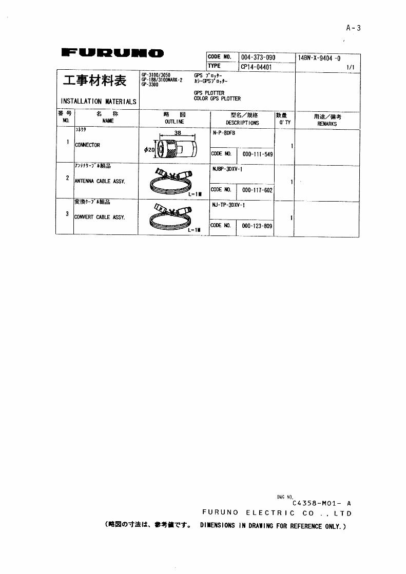
Extending Antenna Cable Length
The standard cable is 15 m long. 30 m and 50 m long exten-sion cable sets are optionally available.
Extension cable line-up
Fabricate the end of antenna cable and attach the coaxial con-nector. Details are shown on next page.
To display unit
: Connector fitted
1 m
Fabricate locally. (See next page.)
ConversionCable Assy.
Antenna Cable
30 m or 50 m1 m
Antenna Unit
Figure 3 How to extend antenna cable

8
Waterproofing the connector
Wrap connector with vulcanizing tape and then vinyl tape. Bindthe tape end with cable-tie.
Figure 4 How to waterproof the connector
How to attach the N-P-8DFB connector
Figure 5 How to attach N-P-8DFB connector

9
WIRING
The figure below shows the location of connectors at the rearof the display unit.
AP IN/OUT
ANT
DATA IN/OUT
FUSE 5A12-24 VDC
DGPS
Autopilot
Ship’s MainsWhite (+)Black (-)
DGPSBeaconReceiver
DATA OUT
ExternalEquipment
Antenna
Ground
Figure 6 Wiring
Grounding
The display unit contains CPU circuits that radiate noise, whichcan interfere with other radio equipment. Ground the unit toprevent mutual interference.
Ground the equipment toprevent mutual interference.
CAUTION

10
DGPS BEACON RECEIVER GR-80CONNECTION (GP-3300 only)
The GR-80 DGPS Beacon Receiver may be connected to theGP-3300 to further improve position accuracy.
GP-3300 DGPS
TD-A
TD-B
RD-A
RD-B
1
2
3
4
5
6
7
RD-A
RD-B
TD-A
TD-B
GND
4
3
2
1
7
GR-80 DATA
Use MJ-A7SPF0003-050(option)
WHT
BLK
YEL
GRN
Figure 7 Connection of DPGS beacon receiver GR-80

11
INITIAL SETTINGS
GD/GP-3300Displaying the initial settings menu
1. Turn on the unit.
2. Press [MENU] and [8] to display the INITIAL SETTINGSmenu.
8 INITIAL SETTINGS
PAGE CHANGE (TO GPS INITIAL SETTINGS)
INTERNAL NAV = ON OFF
EXTERNAL NAV = GPS LC LA DC DR OFF
I/O DATA FORMAT = CIF NMEA183 NMEA180/182
L/L SMOOTHING = 00(0-15) L/L
PLOT INTERVAL 1 = TIME (00M10S) DIST (0.10NM)
PLOT INTERVAL 2 = TIME (00M10S) DIST (0.10NM)
WAYPOINT MARK = ON OFF
EVENT MARK = ON OFF
TRACK(HOLD PLOT) = ON OFF
LINE (HOLD PLOT) = ON OFF
MAGNETIC DEVIATION = AUTO (07°W) MAN (06°E) (0~99)
BEARING = TRUE MAGNETIC
COURSE VECTOR = VECTOR LINE OFF
MARK SIZE = LARGE SMALL
CURSOR SIZE = LARGE SMALL
OWN SHIP MARK = LARGE SMALL
TRACK WIDTH = THICK THIN
RANGE UNIT = NM Km SM
VTD AVG TIME = 10MIN
DATE = 1998-04-10 (YYYY-MM-DD)
TIME = 10: 01: 50
EXTERNAL CLOCK = ON OFF
AUTOPILOT DISPLAY = ON OFF
TD INDICATION = LA LC OFF
*
*
*: For GP-3300 only.
Figure 8 INITIAL SETTINGS menu

12
Navigator selection
Position information, which is used to plot ship’s track, can befed from the internal GPS receiver (GP-3300 only) or an exter-nal navigator. Select one as follows.
3. For the GP-3300, if you are going to use the internal GPSreceiver, simply confirm that INTERNAL NAV is set to ON.
4. Press [↓] to select EXTERNAL NAV.
5. Select navigator; GPS, Loran C, Loran A, Decca, or DeadReckoning.
I/O data format
If position data is fed from an external navigator, select theoutput format of the navigator as follows.
6. Select I/O DATA FORMAT.
7. Select I/O data format of navigator connected.
Note 1: Input and output cannot be selected independently.Note 2: I/O data talker (GP) cannot be changed.
Time and date
8. Select DATE.
9. Enter year in four digits and month and day in two each.Enter leading zeroes in case of single digit month or day.
10. Select TIME.
11. Enter UTC time.
For the GD-3000, press [ENT] followed by [MENU] to finish.For the GP-3300, go to the next page.

13
GP-3300Entering antenna height
1. Press [↑] to place cursor on PAGE CHANGE (TO GPS INI-TIAL SETTINGS).
8 GPS INITIAL SETTINGS
PAGE CHANGE (TO INITIAL SETTINGS)
POSITION FIXING MODE = 2D 3D 2D/3D
GEODETIC DATUM = WGS-84 WGS-72 TOKYO NAD
EURO AUST MISC (007)
HDOP THRESHOLD = 20 (2~99)
TIME DIFFERENCE = 09:00
LATITUDE = 34° 00. 000’ N
LONGITUDE = 135° 00. 000’ E
DELTA LATITUDE = 00. 000’ N
DELTA LONGITUDE = 00. 000’ E
SMOOTHING = 00~00 L/L-SPD (0~99)
ANTENNA HEIGHT = 005 M
COLD START = NO YES
CST SATELLITE NO. = 07
MIN. ELEVATION ANGLE = 05° (5~9)
DESELECT SAT NO. = – –
D.GPS MODE = ON OFF
RTCM VER = 1.0 2.0
BYTE FORM = 8-6 8-8
FIRST BIT = MSB LSB
PARITY BIT = EVEN ODD NONE
STOP BIT = 1 2
BIT RATE = 7 8
BAUD RATES = 300 600 1200
2400 4800 9600
: SELECT ITEM
: SELECT PARAMETER
PROGRAM NO. : 48501050xx
Figure 9 GPS INITIAL SETTINGS menu
2. Press [↓] to select ANTENNA HEIGHT.
3. Enter antenna height above the waterline.
If there is no DPGS beacon receiver installed, press [ENT] fol-lowed by [MENU] to finish.

14
Differential DGPS
When a DGPS beacon receiver is connected to the GP-3300turn on the differential GPS mode and enter specifications ofthe DGPS beacon receiver.
4. Select ON from the D.GPS MODE field.
5. Set RTCM VER, BYTE FORM, FIRST BIT, PARITY BIT,STOP BIT, BIT RATE and BAUD RATES according to speci-fications of DGPS beacon receiver.

15
JUMPER WIRE, DIP SWITCH SETTINGSON GDC BOARD
The GDC Board has jumper blocks and DIP switches whichtailor the specifications of the equipment. Table 4 shows thespecifications available by the jumper blocks and DIP switches.
The data to be output by the #1 and #2 pins of the DATA OUTconnector can be selected by the jumper block JP6 on the GDCBoard. The default setting outputs external navigator positiondata. Input and output data formats cannot be selected inde-pendently.
The external event switch can be selected by J5 on the GDCboard. The default setting outputs data from DATA IN/ OUTconnector.
Table 1 Specifications of jumpers and DIP SW on GDC board
repmuJPID/kcolB
WS
gnitteS noitacificepS
5JoD .rotcennocTUO/NIATADfoatademasstuptuO
vE .hctiwstnevelanretxemorflangiserusolctcatnocstupnI
6J
NI tuptuorotcennocTUOfosnip2#dna1#:0033-PG.reviecerSPGlanretnimorfatadnoitisop
tuptuorotcennocTUOfosnip2#dna1#:0033-DG.tamrofFICniatadtneve
TUO rotagivanlanretxetuptuorotcennocTUOfosnip2#dna1#.atadnoitisop
PID1WS
1# foegnahcretfanonruT).ffoyllamronhctiwS(.seiromemllasraelC.skcoldraobyeknehwro,margorp
4# noitacificeps0033-PG:FFOnoitacificeps0033-DG:NO
3# .yalpsidtolipoedivnotrahcsyalpsiD:FFO.yalpsidtolipoedivnotrahcfoyalpsidselbasiD:NO
2# gnittesyrotcaF:FFO
To set the jumper block JP6;

16
1. Turn off the display unit.
2. Remove the display unit from the hanger and lay it frontside down on a table.
3. Unfasten 13 screws fixing the cover. See the arrows in thefigure below for the location of the screws.
Figure 10 Display unit, rear view
4. Set the jumper block J5/ J6 as appropriate.
J3
IN OUT
J8 J7 J5 J6 J2
J6
GB-94Board
GDCBoard
J5
Figure 11 Display unit, rear view, cover removed

17
4. Reattach the cover.
Note: When no external navigator is connected to the GP-3300,JP6 must be set for “IN" to output position data.

18
I/O DATA DESCRIPTION
Table 2 GP-3300 I/O data description
rotcennoC noitceleSuneM O/I snoitacificepS skrameR
3J ATADTUO/NI
FICtupnI :5,85,75,*4,*3,*2,11FIC pooltnerruC
tuptuO 86,:5,45,35,84,83,82,11FIC pooltnerruC
3810-AEMN
tupnI,AMR,LLG,TBD,WTM,GTV
,CWB,RWB,LPW,BMR,CMRAGG,LLT,ADZ
pooltnerruC
tuptuO ,DTG,LPW,CMR,GTV,LLGAGG,BMR,RWB pooltnerruC
/2810-AEMNC0810
tupnI L/L pooltnerruC
tuptuO tniopyaW,rorrekcartssorC,L/Lgniraeb pooltnerruC
4J TUOATAD
2#,1# tuptuO 3Jurhttupni/tuptuoataD6Jfognittesotgnidrocca pooltnerruC
4#,3# O/I tuptuotnevelanretxe/tuptuoataD5Jfognittesotgnidrocca
,pooltnerruClangistcatnoc
5J TUO/NIPA
3810-AEMNtupnI APFGA pooltnerruC
tuptuO BPA,ETX,GTV,DOB,MAA pooltnerruC
S0810-AEMNtupnI enoN pooltnerruC
tuptuO rorrekcartssorC pooltnerruC
6J SPGDtupnI atad401-CSMCTR 224-SR
tuptuO 3JurhttuptuosaatademaS 224-SR
Table 3 GD-3300 I/O data description
rotcennoC noitceleSuneM O/I snoitacificepS skrameR
3J ATADTUO/NI
FICtupnI :5,85,75,*4,*3,*2,11FIC pooltnerruC
tuptuO 45,35,83,:5FIC pooltnerruC
3810-AEMNtupnI
,AMR,LLG,TBD,WTM,GTV,CWB,RWB,LPW,BMR,CMR
AGG,LLT,ADZpooltnerruC
tuptuO RWB,DTG,LPW pooltnerruC
/2810-AEMNC0810
tupnI L/L pooltnerruC
tuptuO tniopyaW,rorrekcartssorC,L/Lgniraeb pooltnerruC
4J TUOATAD
2#,1# tuptuO 3Jurhttupni/tuptuoataD6Jfognittesotgnidrocca pooltnerruC
4#,3# O/I tuptuotnevelanretxe/tuptuoataD5Jfognittesotgnidrocca
,pooltnerruClangistcatnoc
5J TUO/NIPA
3810-AEMNtupnI APFGA pooltnerruC
tuptuO BPA,ETX,GTV,DOB,MAA pooltnerruC
S0810-AEMNtupnI enoN pooltnerruC
tuptuO rorrekcartssorC pooltnerruC