Embed Size (px)
Citation preview

ColorLogic® 4.0 Installation Guide
©Copyright 2011 Hayward Industries
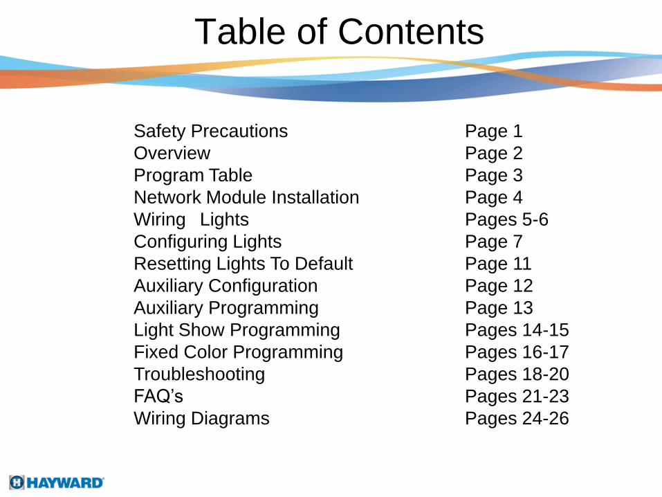
Table of Contents
Safety Precautions Page 1
Overview Page 2
Program Table Page 3
Network Module Installation Page 4
Wiring Lights Pages 5-6
Configuring Lights Page 7
Resetting Lights To Default Page 11
Auxiliary Configuration Page 12
Auxiliary Programming Page 13
Light Show Programming Pages 14-15
Fixed Color Programming Pages 16-17
Troubleshooting Pages 18-20
FAQ’s Pages 21-23
Wiring Diagrams Pages 24-26
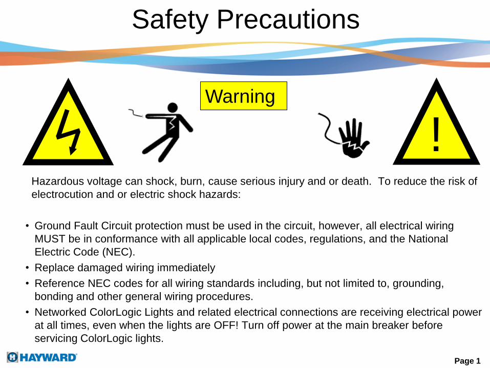
Safety Precautions
Page 1
Hazardous voltage can shock, burn, cause serious injury and or death. To reduce the risk of
electrocution and or electric shock hazards:
• Ground Fault Circuit protection must be used in the circuit, however, all electrical wiring
MUST be in conformance with all applicable local codes, regulations, and the National
Electric Code (NEC).
• Replace damaged wiring immediately
• Reference NEC codes for all wiring standards including, but not limited to, grounding,
bonding and other general wiring procedures.
• Networked ColorLogic Lights and related electrical connections are receiving electrical power
at all times, even when the lights are OFF! Turn off power at the main breaker before
servicing ColorLogic lights.
Warning
!

Compatibility
• The AQL-COLOR-MODHV is compatible with all Goldline Controls Pro Logic PS controls
operating with software version 4.00 or greater and whose enclosures provide a cutout for
installation.
• The ColorLogic Network Module will only operate with Generation 4 or later Hayward
ColorLogic 120VAC pool/spa light(s).
Description
• The ColorLogic Network Module is used with the Pro Logic to fully control the color, speed,
motion and brightness of pre-set light shows in a compatible Hayward ColorLogic pool/spa
light(s). After installing the ColorLogic Network Module and enabling the function in the Pro
Logic, the user can program various parameters to fully customize their pool/spa light(s)
operation.
• The ColorLogic Network Module can be used to control up to 32 pool or spa lights
simultaneously. This method of control features 2 user defined programs; five fixed colors
and eleven color-changing shows. All fixed colors and shows can be modified or changed.
The factory set colors and shows are listed in the Program Table on the next page and can
also be found on the color laminated card included with the light. A color chart can be found
on the same card and will help when programming colors for the ColorLogic lights.
Overview
Page 2
Program Table
Page 3

Network Module Installation
Holding the modem at an angle,
insert the top of the modem into
the cutout.
Step A
Insert the bottom of the modem in place and rotate
the modem until it seats into the cutout.
Step B
Page 4
Remove the plastic plate by sliding it
towards the front of the enclosure.
Step C
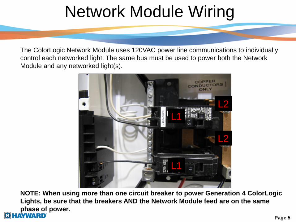
The ColorLogic Network Module uses 120VAC power line communications to individually
control each networked light. The same bus must be used to power both the Network
Module and any networked light(s).
Network Module Wiring
NOTE: When using more than one circuit breaker to power Generation 4 ColorLogic
Lights, be sure that the breakers AND the Network Module feed are on the same
phase of power.
Page 5
L1
L1
L2
L2
Network Module Wiring
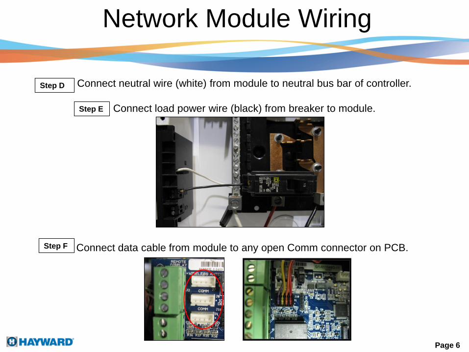
Connect neutral wire (white) from module to neutral bus bar of controller.
Connect load power wire (black) from breaker to module.Step E
Step D
Connect data cable from module to any open Comm connector on PCB.Step F
Page 6

ColorLogic Lights Wiring
Connect the pig-tail
wire of the GFCI
breaker to the
neutral bus bar.
Step G
Connect the line power wire
(from breaker) and load power
wire (to lights) to the Lights
Relay.
Step H
To light(s)
Connect the load neutral wire
(from light) to the GFCI breaker.Step I
From light(s) Page 7

Configuring Lights
Note: Once the ColorLogic configuration process begins,
there is no way to exit and the process must be completed.
During ColorLogic configuration, the Pro Logic will find all networked lights in the
system and assign an identification number to each using the prefix "LT".
Press the + button to activate
ColorLogic options
Step J Press the + button to find ColorLogic
lights
Step K
Page 8
Configuring Lights
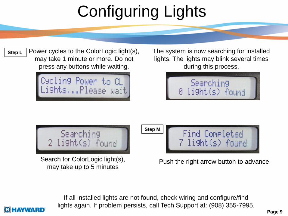
Power cycles to the ColorLogic light(s),
may take 1 minute or more. Do not
press any buttons while waiting.
The system is now searching for installed
lights. The lights may blink several times
during this process.
Push the right arrow button to advance.
If all installed lights are not found, check wiring and configure/find
lights again. If problem persists, call Tech Support at: (908) 355-7995.
Search for ColorLogic light(s),
may take up to 5 minutes
Step L
Step M
Page 9
Configuring Lights
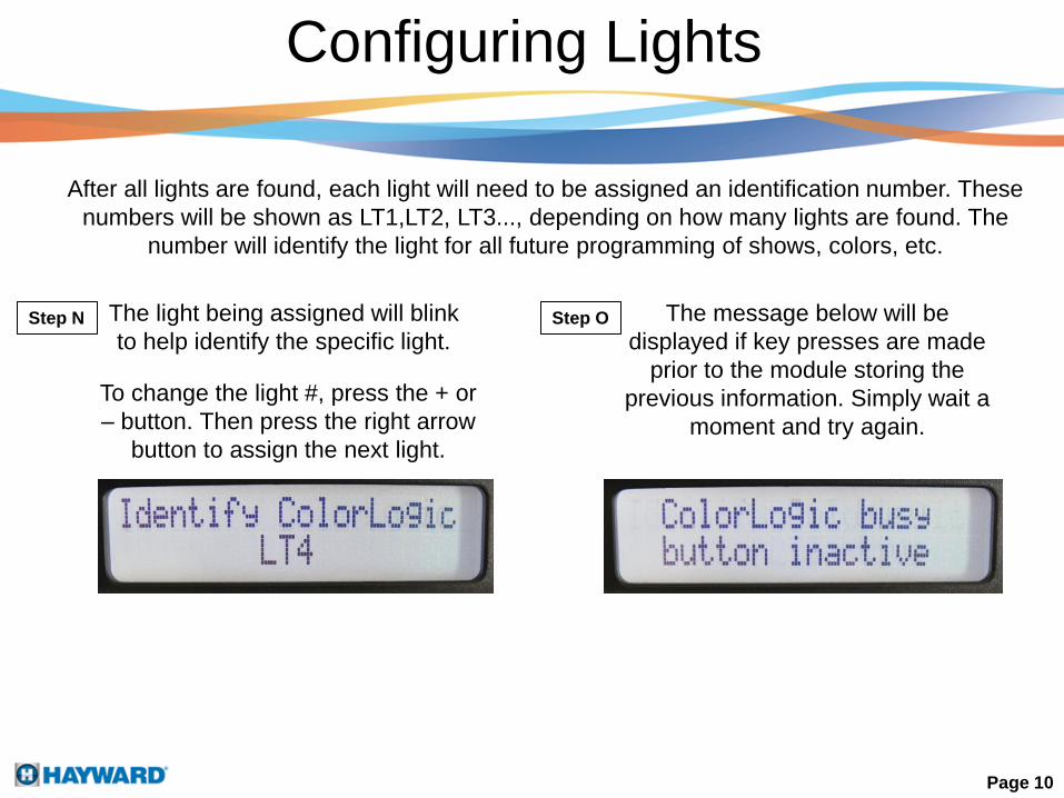
After all lights are found, each light will need to be assigned an identification number. These
numbers will be shown as LT1,LT2, LT3..., depending on how many lights are found. The
number will identify the light for all future programming of shows, colors, etc.
The light being assigned will blink
to help identify the specific light.
To change the light #, press the + or
– button. Then press the right arrow
button to assign the next light.
The message below will be
displayed if key presses are made
prior to the module storing the
previous information. Simply wait a
moment and try again.
Step N Step O
Page 10
Resetting Lights to Default
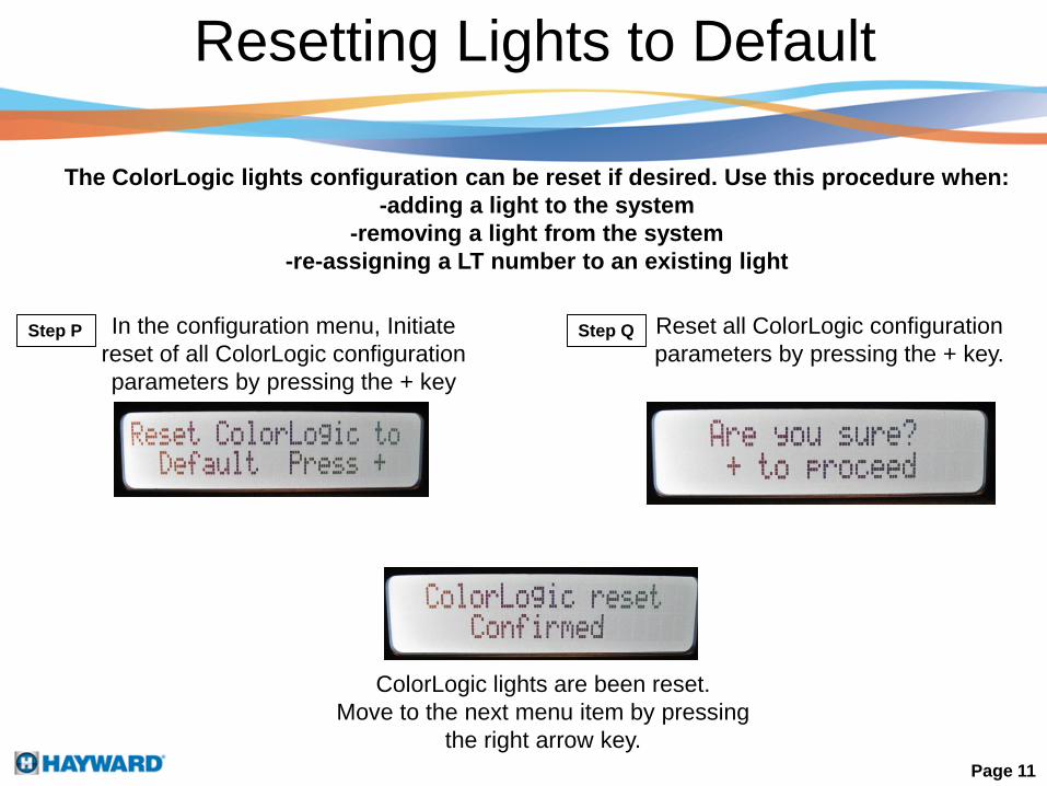
The ColorLogic lights configuration can be reset if desired. Use this procedure when:
-adding a light to the system
-removing a light from the system
-re-assigning a LT number to an existing light
In the configuration menu, Initiate
reset of all ColorLogic configuration
parameters by pressing the + key
Step P Step Q Reset all ColorLogic configuration
parameters by pressing the + key.
ColorLogic lights are been reset.
Move to the next menu item by pressing
the right arrow key.
Page 11

Auxiliary Configuration
Any Aux output can be configured to control a ColorLogic fixed color or light show,
(Aux 4 is used for example in this guide). A virtual Aux output can also be used on Pro Logic
Virtual models (see the Pro Logic manual for more information). A ColorLogic light can be
assigned to more than one Aux and if more than one show is desired, additional Aux outputs
can be configured
Page 12
Step Q Select the desired Aux and press +.
Step R Scroll thru the list of available names
using the + and – buttons. Select the
name you want displayed and press
the right arrow button.
Select the function for how the Aux
will operate ( Manual, Timeclock, or
Countdown). Press the right arrow
button to move to the next step.
Step S
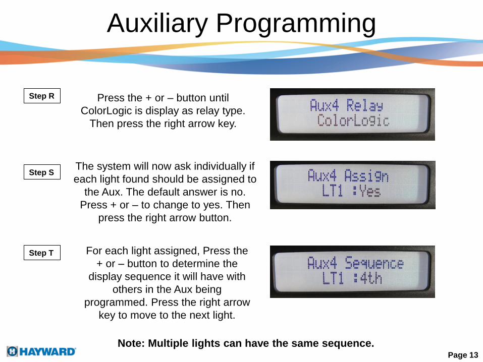
Auxiliary Programming
Page 13
Step R Press the + or – button until
ColorLogic is display as relay type.
Then press the right arrow key.
Step S
Step T
The system will now ask individually if
each light found should be assigned to
the Aux. The default answer is no.
Press + or – to change to yes. Then
press the right arrow button.
For each light assigned, Press the
+ or – button to determine the
display sequence it will have with
others in the Aux being
programmed. Press the right arrow
key to move to the next light.
Note: Multiple lights can have the same sequence.
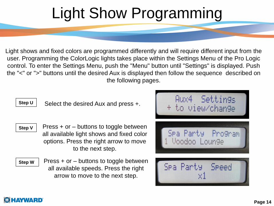
Light shows and fixed colors are programmed differently and will require different input from the
user. Programming the ColorLogic lights takes place within the Settings Menu of the Pro Logic
control. To enter the Settings Menu, push the "Menu" button until "Settings" is displayed. Push
the "<" or ">" buttons until the desired Aux is displayed then follow the sequence described on
the following pages.
Light Show Programming
Select the desired Aux and press +.Step U
Press + or – buttons to toggle between
all available light shows and fixed color
options. Press the right arrow to move
to the next step.
Step V
Press + or – buttons to toggle between
all available speeds. Press the right
arrow to move to the next step.
Step W
Page 14

Light Show Programming
Press + or – buttons to toggle between
all available motion options. Press the
right arrow to move to the next step.
Step X
Step Y Press + or – buttons to toggle between
all available brightness options. Press
the right arrow to move to the next step.
Note: When motion is set to OFF, there is no delay and all lights will illuminate at
the same time. When motion is set to a positive value (+0.2 to +1.2), the order of
illumination will start from the lowest LT number and advance to the highest. If a
negative motion value is selected (-1.2 to -0.2), the illumination sequence will be the
opposite (highest LT to lowest).
Page 15
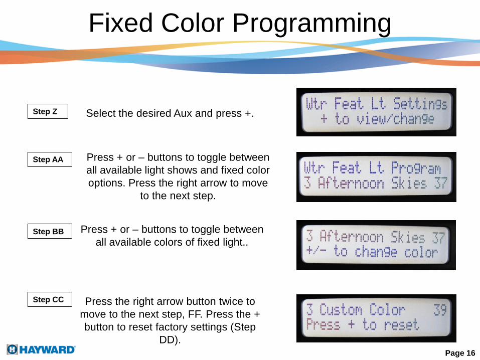
Fixed Color Programming
Select the desired Aux and press +.Step Z
Page 16
Press + or – buttons to toggle between
all available light shows and fixed color
options. Press the right arrow to move
to the next step.
Step AA
Press + or – buttons to toggle between
all available colors of fixed light..
Press the right arrow button twice to
move to the next step, FF. Press the +
button to reset factory settings (Step
DD).
Step CC
Step BB
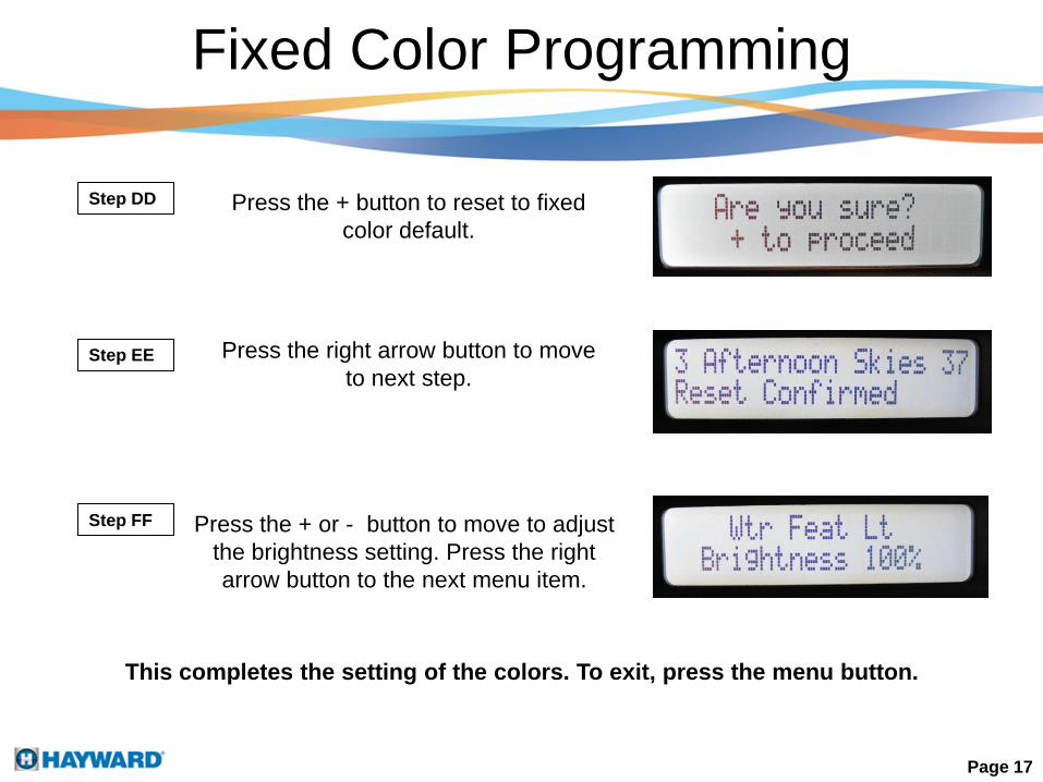
Fixed Color Programming
Page 17
Step DD Press the + button to reset to fixed
color default.
Press the right arrow button to move
to next step.Step EE
Step FF Press the + or - button to move to adjust
the brightness setting. Press the right
arrow button to the next menu item.
This completes the setting of the colors. To exit, press the menu button.

Troubleshooting
ColorLogic Lights system is not recognized by the Pro Logic and no ColorLogic
menu options are shown.
Verify that the Lights indicator light automatically turns on upon applying power to the Pro
Logic. If the indicator does not turn on, the Pro Logic is not communicating with the Network
Module which means you should check the RS-485 connection (i.e., the four wire
connection) between the Pro Logic main board and the Network Module.
Multiple lights blink at the same time during the identification process.
During the identification process only a single light should be blinking at any given time.
Each time the right arrow is pressed, a command is sent to turn off the current light and to
start the next light blinking. If two lights are blinking, previous light did not process the
command to turn off. Use the “Left Arrow” to return to the previous light and then continue
to identify the lights using the right arrow.
Page 18

Troubleshooting
Lights are running different shows when they should all be running the same
show.
Each light maintains a local set of information which identifies the AUX buttons it is
assigned to. Each light also maintains a local copy of the actions (e.g., which light show
to run when an AUX button is pressed) it takes in response to the AUX button.
If the settings menu is adjusted when a light is powered off or not connected to the
network, information can get out of sync with the other lights. When this happens, the
corrective action is to adjust the settings for the AUX while the light is powered on.
How can I tell if the lights are operating correctly?
Power off the lights for at least one minute. Once power is applied to the light, it should
immediately turn on an all white light for approximately fifteen seconds. If the light is
installed with a pool controller and has been configured with a working Network Module,
the light will flash red, green, and blue before turning off after fifteen seconds of white has
been displayed.
Note: For larger systems, this cycle of red, green and blue can last up to 3 minutes. If the
light is set up to run in a stand alone mode, it will start the light show after the fifteen
seconds of white light.
Page 19
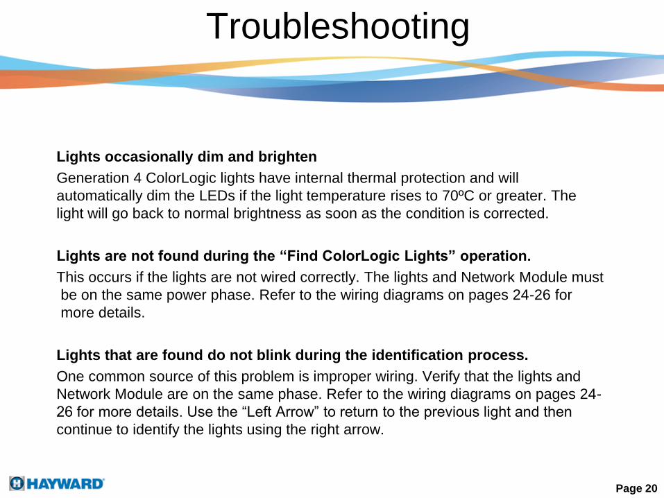
Lights occasionally dim and brighten
Generation 4 ColorLogic lights have internal thermal protection and will
automatically dim the LEDs if the light temperature rises to 70ºC or greater. The
light will go back to normal brightness as soon as the condition is corrected.
Lights are not found during the “Find ColorLogic Lights” operation.
This occurs if the lights are not wired correctly. The lights and Network Module must
be on the same power phase. Refer to the wiring diagrams on pages 24-26 for
more details.
Lights that are found do not blink during the identification process.
One common source of this problem is improper wiring. Verify that the lights and
Network Module are on the same phase. Refer to the wiring diagrams on pages 24-
26 for more details. Use the “Left Arrow” to return to the previous light and then
continue to identify the lights using the right arrow.
Troubleshooting
Page 20

Even when the lights are off, why does the Lights indicator on the Pro Logic control
panel always turn on whenever the Pro Logic is turned on?
The Lights indicator reflects the state of power to the lights and power is always applied to the
lights when the pool controller is on. The lights run a light show, turn on, or turn off under
program control which is initiated from the Pro Logic. In general, lights will have power applied
even if the lights are not displaying visible light.
Can the Lights relay be configured when used with a ColorLogic Lights Generation 4.0
(CLLG4) system?
No. The Pro Logic automatically assigns the Lights relay to the CLLG4 system and enables
power to the light. Lights are always powered when the pool controller is powered on. To force
this relay off, use Service Mode or System Off mode.
How does the Lights button work?
The Lights button is used for emergency white lighting of the pool. The Lights button sends a
command to toggle the light state. The lights will either turn on (full white) or off. If you press
the button and the lights remain off, press the button again to turn the lights on full white. If you
press the button and the lights stay on, press the button again to make the lights turn off.
Normal color operation of the lights is done through Aux buttons.
FAQs
Page 21

Can lights be assigned to multiple Aux buttons?
Yes. Moreover, different light shows can be set up for each Aux button. For instance, a light
can be assigned to Aux 1 and Aux 2. Aux 1 can be set to Voodoo Lounge while Aux 2 can
be set to Deep Blue Sea.
What happens when lights are assigned to multiple Aux buttons?
Lights process the command associated with the last button which was turned on.
Do all lights have to be assigned to the same Aux button?
No. A subset of lights can be assigned to any Aux button. For instance, if you are using a
Pro Logic with eight Aux buttons, pool lights can be assigned to Aux 4 and spa lights can be
assigned to Aux 5. If Aux 4 and Aux 5 are set up this way, different light shows can be
assigned to Aux 4 and Aux 5. Moreover, if lights are separated between pool and spa, both
the pool and spa lights can run different light shows at the same time. Another Aux can run
all the lights at once.
FAQs
Page 22

Can light show settings be changed while a show is running?
Yes. The settings for a show can be changed while a show is running. If you pause
a few seconds between key presses, you will be able to see the effect of the
changes while the show is running.
How do lights go from stand alone mode to program control mode?
Lights are originally shipped in stand alone mode. This mode allows the light shows
to be controlled using power line interrupts (toggling power to the light) and is similar
to the previous generation lights. The lights automatically go into program control
mode when they are configured with a Pro Logic pool controller and AQL-COLOR-
MODHV.
How do lights go from program control mode to stand alone mode?
Lights which have been installed and configured with a pool controller can be
returned to stand alone mode by using the “Reset ColorLogic” option in the Pro
Logic configuration menu. You also will need to remove the network module and
move the lights input and output power to another relay.
Can I mix ColorLogic 4.0 lights with ColorLogic 2.5 lights in stand alone
mode?
No. The timing of light shows in version 4.0 lights is not the same as version 2.5
lights. The lights will not perform at the same speed or intensity.
FAQs
Page 23
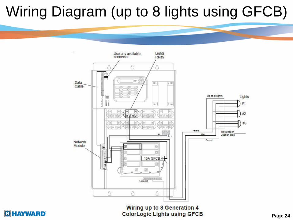
Wiring Diagram (up to 8 lights using GFCB)
Page 24

Wiring Diagram (up to 8 lights using GFCI receptacle)
Page 25
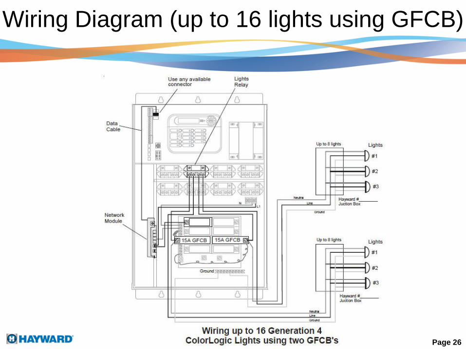
Wiring Diagram (up to 16 lights using GFCB)
Page 26