Embed Size (px)
Citation preview

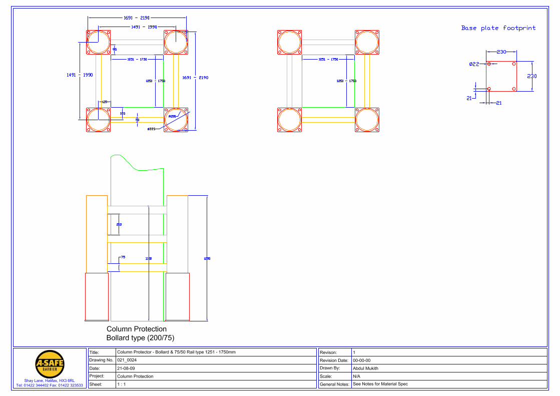
Column Protection
Bollard & Rail
Post & Rail

Bollard & Rail Column Protection
Post & Rail Column Protection

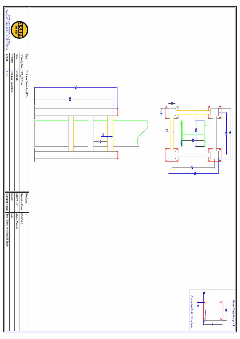

Car park
Car Park Barrier
Car Park Barrier + Anti Climb Attachment

A M O R E F L E X I B L E S O L U T I O N
In a factory one small accident can lead to a verylarge bill.
A-Safe Traffic Barrier is the perfect way to avoid
unnecessary damage to your property. It will protect walls,
building supports, valuable machinery and vulnerable
equipment by repelling wayward fork lift trucks, lorries,
factory sweepers and cars.
When used in conjunction with our pedestrian rail
attachment they offer exceptional protection for personnel
and customers. Gates and Health & Safety signage can be
incorporated with the pedestrian rail attachment. The vivid
colours of our traffic barriers also make them ideal for
highlighting designated vehicle routes.
C A R P A R K B A R R I E R
C ALL 01422 344402 FAX 01422 323533 OR VIS IT www.asafe.co.uk
B A R R I E R
In a car park even a small bump with the perimeter structure can lead to expensive vehicle body and structure repairs. Even worse, in multi-storey car park upper levels a vehicle could be driven off an edge. A-Safe Car Park Barrier is the perfect way to avoid unnecessary damage to both vehicles and structures. It will protet perimeter fencing or walls and its inherent flexibility and impact absorption properties ensures any vehicle hitting it will suffer little or no damage. It can be used as a barrier to define and segregate a car park perimeter. The 445mm impact height centre and the optionally available anti-climb attachment make the barrier fully compliant with current car park regulations.
In line with our continuousimprovement policy wereserve the right to changeproduct specificationswithout prior notice.
An A-Fax Affiliated Company
MAKE SURE YOU ARE COMPLIANT WITH HSC WORKPLACE REGULATIONS 1992 AND
EC WORKPLACE DIRECTIVE 89/654/EEC
Shay Lane Halifax HX3 6RLC ALL 01422 344402 FAX 01422 323533 OR V IS I T www.asafe . co .uk
•
•••••••••••••••
Ideal for car park perimeter structures and for edge protectionin multi-storey car parksHigh impact absorption propertiesAssembly from standard modular componentsSupplied with post floor fixingsInternal or external usageTested and certified to British StandardsStrong, durable and flexibleAestheticallY pleasingHighly visibleEasy to installNo screws or welding requiredNo paintingLittle or no maintenanceSimple to repairReusableCompetitively pricedPatent pending
560
¯200
445
1100
10 1
1600 250
1160
All dimensions shown in mm
Base Plate Footprint
180
15
15¯14 ¯14 to takeM12 fixing bolts
15
15
18015
170
6
10
2725
75
CAR PARK BARRIER DIMENSIONS
The anti-climb attachment is supplied as pre-assembled panels for fitting into the attachment posts. Where two barrier sections are butted together at 90° corner ant-climb units are available.
The anti-climb attachment should always be mounted on the non-traffic side of the car park barrier to which it is fitted.


Manual reference CPB001
Rev2 Issued 17/03/09
© A-Safe (UK) Ltd 2008
A-Safe (UK) Ltd Shay Lane Halifax HX3 6RL
Car Park Barrier
Car Park Barrier without A-Safe Pedestrian Edge Restraint
Car Park Barrier with A-Safe Pedestrian Edge Restraint

1.0 Introduction 2.0 A-Safe Company Structure and contact details 3.0 Applicable Standards and regulations 4.0 Load Testing and Conformance Requirements 5.0 Technical Product Information 6.0 Dimension Drawing and Component Part Details 7.0 Cleaning and maintenance schedule 8.0 Appendix 1 – Test Certificates 9.0 Appendix 2 – Fixing Bolt Test Results
Contents
1.0 Introduction
This manual provides information regarding applicable standards andregulations, technical product information, component and dimension detailsand care and maintenance requirements for the range of barriers availablefrom A-Safe (UK) Ltd for installation and use in Car Park Environments. The products are installed within a car park as static internal fixtures and thismanual therefore has no product operation section. As standard the products are supplied in a yellow/black colour combinationand are also available in a cool grey colour option. The drawings andillustrations contained in this manual will generally show the barrier in itsstandard black and yellow colour format. Whatever colour option is providedthe products are identical. The products are of modular construction and, with the exception of the steelbase plates, are manufactured from lightweight extruded plastic sections. They are quickly and easily assembled without the use of nuts and bolts,brackets or welding. Installation is achieved by anchoring the post baseplates to a concrete surface using high quality steel fixing bolts, supplied withthe products as standard. The Car Park Barrier is assembled from end and mid post modules with200mm OD rails between adjacent post modules and is installed as standardon 1600mm post centres. Where necessary a reduced post centre is used toprovide an assembled barrier section of a given overall length. The post centre used on the Car Park Barrier never exceeds 1600mm. Thisis due to the fact that the Car Park Barrier section that was tested to confirmcompliance with the load requirements stated in BS6399 was installed on1600mm post centres, see Sections 4.1 and 4.2. Each post is anchored via a base plate into concrete using 4 fixing bolts in100mm deep drilled holes. The barrier components and dimensions areshown in the tables and drawings in Section 6.0.

Contact with A-Safe may be made by post, telephone, fax or emailaddressed to the relevant contact. Alternatively information is obtainable viathe companies’ web site A-Safe (UK) Ltd Shay Lane Halifax West Yorkshire HX3 6RL T 01422 344402 F 01422 323533 e [email protected] w www.asafe.co.uk Contacts Health and Safety James Smith [email protected] Technical Luke Smith [email protected] Sales Neil Clifford [email protected] Repairs Luke Smith [email protected]
2.0 Company Structure and Contact Details

The barrier supplied by A-Safe has been designed and produced to becompliant with the following standards and regulations. Where applicable,specific references are made to these documents in this manual.
• BS6180 Barriers in and about buildings – Code of Practice
• BS6399 Loading for buildings Part 1 Code of practice for dead and imposed loads
• Building Regulations 2000 – Approved Document K
• DETR Edge Protection in Multi-Storey Car Parks – Design Specification and Compliance Testing Final Report October 2001
In addition recommendations have also been made in reports published by the Institute of Civil Engineers and the Institution of Structural Engineers which were incorporated in the report Partners in Innovation published by the Office of the Deputy Prime Minister in 2002.
3.0 Applicable Standards and Regulations

The method of calculation for the horizontal impact that must be withstood bya rigid barrier system is detailed in BS6399. For perimeter barriers thecalculated figure is 152kN, which is the horizontal impact force imparted by avehicle weighing 1500kg moving at a speed of 4.5m/sec (16km or 10 milesper hr). The impact force must be withstood at an impact height of 445mmas determined in the DETR Edge Protection in Multi-Storey Car Parks FinalReport October 2001. Both the DETR Final Report and BS6180 state that where a vehicleapproach to any vehicle restraint exceeds 20m in a straight line, such asdeck ends or opposite down ramps a barrier must be able to withstand animpact at 2 x Force (Twice–Force), i.e. 304kN, see section 4.2.2.2. Theimpact height at which the Twice-Force must be withstood is stated in theDETR report as being 445mm. Where a Pedestrian Edge Restraint is required, see section 4.2.3.2 therequirements are given in the Building Regulations Approved Document,BS6180 and BS6399. The impact force load the restraint must withstand is areduced impact force load of 1.5kN/m2 on the restraint handrail, 1.5kN/m2on the restraint area or 1.5kN/m2 or 1.5kN at any point location on therestraint.
4.0 Load Testing and Conformance Requirements
4.1 Load Test Requirements
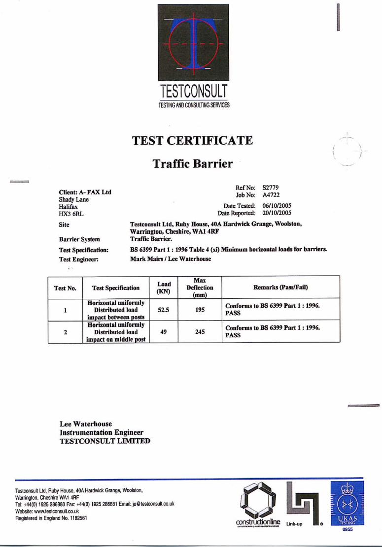
Both the Car Park Barrier and Pedestrian Edge Restraint, A-Safe use the term Anti-climb Attachment, supplied by A-Safe (UK) Ltd have been tested as complying with the impact loads specified in section 4.1 above. Copies of the certificates are contained in Section 8.0, Appendix 1 of this manual. Being manufactured from extruded plastic sections the assembled Car ParkBarrier supplied by A-Safe exhibits an inherent flexibility. This means that theequivalent impact force loads the Barrier must withstand are lower than the152kN that must be withstood by a rigid barrier. The equivalent loadsindicated on the test certificate in Appendix 1, where the barrier system istermed Traffic Barrier, actually exceed the static load requirement for a rigid barrier system of 152kN. During conformance testing the Pedestrian Edge Restraint, shown as TrafficPlus Barrier, Vertical Infill Panel on the certificate in Appendix 1, withstood aload of 2.25kN, which exceeds the specified load requirement of 1.5kN indicated on the certificate.
4.2 Standard Conformance
4.2.1 Impact Force Load Requirements

Both BS6399 and the DETR Final Report October 2001 take into accountthat vehicle impact with barrier mounted at ramp edges is highly unlikely tooccur normally to the vehicle barrier and will be at a reduced incident angle. Accordingly the impact force load requirement that barriers installed onramps have to withstand is reduced to one half of the load (½ force) for horizontal impact given in Section 4.1. The standards allow the ½ forcerequirement to be achieved by reducing the barrier post centre span to 1.6times its standard value. For barriers installed on ramp edges A-Safe supply the standard Car Park Barrier product the same impact force load protection as required forperimeter barriers, thereby providing a higher level of impact protection thanrequired.
4.2.2 Other Vehicle Barrier Conformance Requirements
4.0 Load Testing and Conformance Requirements
4.2.2.1 Ramp Edge Protection
4.2.2.2 Ends of Decks and Opposite Down Ramps
The DETR Edge Protection in Multi-Storey Car Parks report October 2001requires that when a vehicles approach length to any vehicle restraint exceeds20m in a straight line, at the end of decks or ramps, the vehicle restraint mustbe capable of withstanding twice the calculated static force acting at an impactheight of 445mm. The report states that this can be achieved by reducing the horizontal span(post centre) of the restraint to 0.6 times its standard value. Accordingly to meet this requirement in locations where twice force is requiredthe standard post centre of the A-Safe Car Park Barrier is reduced from1600mm to 960mm.
4.2.2.3 Split Level Deck Edge Protection
Where the drop between split deck levels is greater than 380mm thestandards and regulations require that edge protection must be provided toprevent vehicles falling between deck levels over the open edge space. The barriers installed in such situations must meet the same requirements asbarriers installed at perimeter edges. The standard Car Park Barrier Productsupplied by A-Safe meets these requirements.

The Building Regulations, BS6399, BS6180 and DETR Final Report 2001detail requirements which must be met by the Edge Restraint and where it is required. The primary requirement is for Pedestrian Edge Restraints to beused in locations where pedestrians, including children, from accidentallyendangering themselves. The load requirements for Pedestrian Edge Restraints are contained in BS6399 and have already been addressed in sections 4.1 and 4.2 of thismanual. The additional requirements for a Pedestrian Edge Restraint can besummarised as follows:
Gaps in the Restraint System used that would allow the passage of a100mm diameter sphere are not allowed
Where the vehicle barrier is located inside the Edge Restraint Systemused, the Pedestrian Edge Restraint must be provided to a height of1.1m measured above the highest reachable by a rise of less than550mm.
The Edge Restraint system supplied by A-Safe is a panel based system, A-safe use the term Anti-Climb Attachment to refer to the system. The systemis an add-on attachment to the standard Car Park Barrier. The panel design is such that there no gaps that will permit access of a100mm diameter sphere. When fitted to the Car Park Barrier, as there is noreachable foothold at a height less than 550mm, the Anti-climb Attachment system is provided to comply with the 1.1m height requirement
4.2.3 Pedestrian Edge Restraint Requirements
4.0 Load Testing and Conformance Requirements
4.2.3.1 Design Criteria
4.2.3.2 Required Locations
The standards and regulations require that Pedestrian Edge Restraints are used at perimeter edges, including ramps and split deck levels, where there is a drop greater than 380mm. The DETR Final Report October 2001 states that Pedestrian Edge Restraint on ramps is not required where the drop to the adjoining deck is less than 600mm providing that pedestrians are directed not to use the vehicle ramps.

5.0 Technical Product Information
The material used to manufacture the barrier: • Contains no substances classified as hazardous. • Is not classified as dangerous • Burns but is not classified as flammable. Water in a spread jet, dry chemicals or foam are suitable extinguishing media. • Has a working environmental temperature range of –10 to +50 °C • Has an ignition point of 360 °C in the presence of a burner flame and 409 °C in the absence of a burner flame. • Will not give off toxic or noxious fumes should it ignite • Contains no re-cycled material but is itself 100% recyclable
5.1 Technical Information Summary
5.2 Specific Technical Information
5.2.1 UV Protection*
Barriers may be installed externally or internally within car parks and aretherefore exposed to daylight (containing UV radiation) to a greater or lesserextent. To protect the products against UV degradation A-Safe use a UV protectionpackage in their extruded sections as standard. This package provides arecommended performance period for UV protection of 15-20 years out doorsin Northern Europe and 10 years in the southern hemisphere. * Further technical details regarding UV Protection are available on request
5.2.2 Operational Temperature Range
The working environmental temperature range specified for the A-Safe Barrierproducts is -10°C to +50°C. The Izod impact strength of the material has beentested by the material manufacturers to the relevant standards. The product will perform below -10°C but exhibit a reduction in mechanicalperformance. Below –20°C the extruded sections from which the products areassembled reaches its glass transition temperature (the temperature at whicha polymer becomes solid). Below this temperature it-10 °C is prone to crackingunder point load impact conditions, however it will still stop vehicles under theforce requirements set out in British Standard BS6399 and required by theDETR Edge Protection in Multi-Storey Car Parks report.

5.0 Technical Product Information
5.2.3 Ignition Point and Flammability
The ignition point of the material from which the extruded sections aremanufactured is 360°C (in the case of burner flame being present) and 407°C(in the absence of a burner flame). The rate at which the material burns is 100mm/min. The materials’ Combustible class is HB. In the unlikely event that an ignition point of 360°C or 407°C occurs, if thistemperature is reached most of the contents and structure in which thebarriers are located will already have been destroyed or suffered severedamage. The barrier materials will not give off any toxic or noxious fumes should theybe ignited.
The same material type is used extensively in automotive parts, e.g. bumpers, radiator expansion tanks, brake fluid reservoir, windscreen washer tanks and parts of ventilation systems.

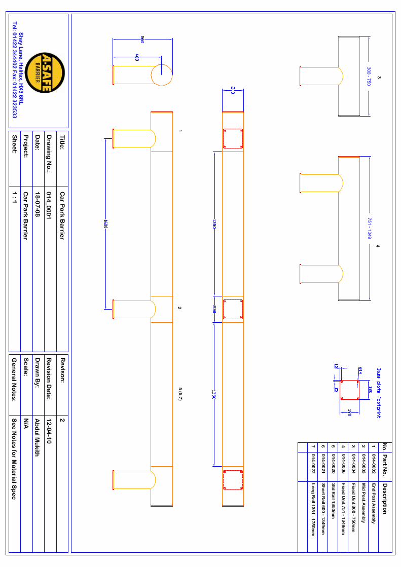
No Description Product Code
Drawing Ref.
Posts
1 End Post Assembly 014_0002 1 2 Mid Post Assembly 014_0003 2
Rails
3 Standard Rail 1350mm 014_0020 3 4 Short Rail 600mm – 1349mm 014_0021
Fixed Units
5 Fixed Unit 300 – 750mm 014_0004 6 Fixed Unit 500mm 014_0005 7 Fixed Unit 751 – 1349mm 014_0006
Other Parts
8 Post Base Plate 001_0001 4 9 Rail End Cap 904_0004 5 10 Locking Pin 904_0005 6 11 S12/40 Fixing Bolt 901_0021
6.0 Dimension Drawing and Component Part Details
6.1 Car Park Barrier
6.1.1 Component Parts
The car park barrier is assembled from modular components. Standard raillengths are used to assemble a barrier section on 1600mm post centres.However it is unlikely that the overall barrier section will allow assembly of arequired barrier section length using only standard rails. A short non-standardrail is available which, in combination with standard rails, allows barriersections to be assembled to any desired overall length. The minimum barrier section length that can be assembled using modularcomponents is 1350mm. In circumstances where shorter section lengths arerequired pre-assembled fixed units are available which allows barrier sectionsdown to 300mm to be catered for within a required barrier layout. All post fixing bolts, 4 per post, needed to install a barrier section are suppliedas part of the post assemblies. Details of the available component parts aredetailed in the table below.
6.0 Dimension Drawing and Component Part Details
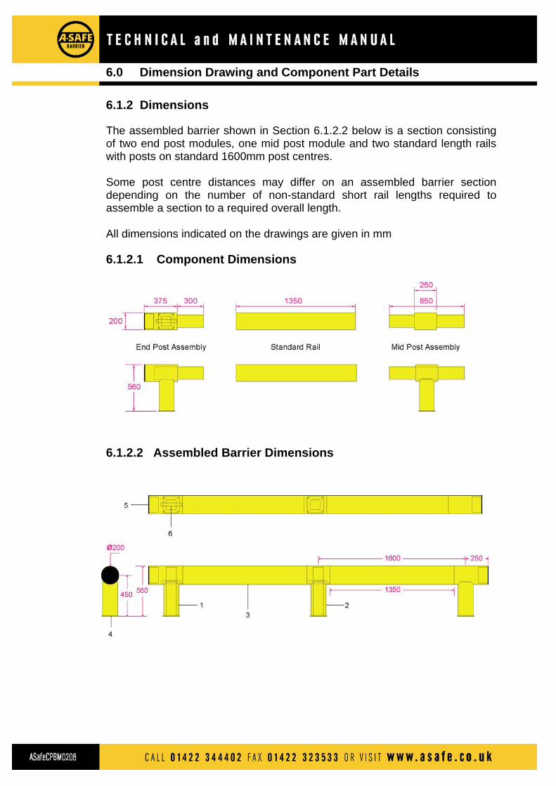
6.1.2 Dimensions
The assembled barrier shown in Section 6.1.2.2 below is a section consistingof two end post modules, one mid post module and two standard length railswith posts on standard 1600mm post centres. Some post centre distances may differ on an assembled barrier sectiondepending on the number of non-standard short rail lengths required toassemble a section to a required overall length. All dimensions indicated on the drawings are given in mm
6.1.2.1 Component Dimensions
6.1.2.2 Assembled Barrier Dimensions

6.0 Dimension Drawing and Component Part Details
6.1.2.3 Corner Layout and Base Plate Footprint

No Description Product Code
Drawing Ref.
Posts
1 Universal Post Assembly 016_0002 1 2 Mid Post Assembly 014_0003 2
Attachment Panels
3 Standard Attachment Panel 1600mm 016_0020 3 4 Non-std Attachment Panel 850mm – 1599mm 016_0021 5 End Attachment Panel 016_0023
Attachment Corner Units
6 90° Internal Corner Unit 016_0024 7 90° External Corner Unit 016_0025
Other Parts
8 Attachment Post Mounting Bracket 001_0025 4 9 Attachment Post End Cap 901_0002 5 10 Attachment Post 75/50 Hole Blanking Cap 901_0022 11 Locking Pin 904_0001 6 12 Attachment Post S12/40 Fixing Bolt 900_0004
6.0 Dimension Drawing and Component Part Details
6.2.1 Component Parts
The Anti-climb attachment is assembled and fitted to the Car Park Barrier afterthe Car Park Barrier has been assembled and the post base plates located ontheir fixing bolts. Like the Car Park Barrier it is assembled from modularcomponents, posts and panels. The panels are supplied in standard and non-standard lengths to suit the rail lengths used to assemble the Car Park Barriersection. The Anti-Climb Attachment posts and panels are always fitted to the non-traffic side of the Car Park Barrier rail. The Attachment posts are fitted withmounting brackets to allow fitting and securing to the Car Park Barrier postassemblies using the two rear base plate fixing bolts that anchor the Car ParkBarrier post modules. The Attachment post is further secured by using a singlefixing bolt at the rear of the Attachment post mounting bracket. End panel Anti-Climb Attachment panels are also supplied to ensure that thePedestrian edge restraint system is the same overall length as the Car ParkBarrier to which it is fitted. Details of the Anti-climb Attachment Componentparts are given in the table on the following page.
6.2 Anti-climb Attachment

6.0 Dimension Drawing and Component Part Details
6.2.2.1 Component Dimensions
6.2.2 Component and Assembled Dimensions
The drawing in Section 6.2.2.2 shows the standard Anti-climb Attachmentcomponents fitted to a Car Park Barrier consisting of two end post modules,one mid post module and two standard length rails with posts on standard1600mm post centres. Some post centre distances may differ on an assembled barrier sectiondepending on the number of non-standard short rail lengths required toassemble a section to a required overall length. All dimension given on the drawings are in mm
6.1.2.2 Assembled Attachment Dimensions

6.0 Dimension Drawing and Component Part Details
6.2.2.3 Corner Layout and Post Mounting Bracket Details

7.0 Cleaning and Routine Maintenance Schedule
7.1 General The materials used in construction of the barrier products, extrudedpolypropylene sections and steel base plates, together with the designtechniques employed in relation to barrier assembly and performanceprovide a barrier that requires minimal routine maintenance tasks to beundertaken. Routine and other maintenance is required to ensure correctproduct performance and to maintain its' appearance and high visibility.Attention is drawn to sub-section 6.4 7.2 Cleaning
Dust and other particulate material can be easily removed by simply wipingthe product with a damp cloth. Marks on the product caused by knocks and scrapes can generally beremoved using a mildly abrasive liquid or cream cleaner. Cleaning should be performed after impact or barrier repair, otherwisecleaning to preserve general barrier appearance and cleanliness can bedone at periods determined by the car park operator 7.3 Maintenance Routine maintenance is required to ensure barrier integrity and thereforeperformance is maintained over time. Areas where barrier integrity can beaffected are post base plate fixing bolt nuts not being at the correct torquesettings and damage occurring to barrier component parts (post modulesand rails). It is highly unlikely that every occurrence of impact on the barrier will beknown about or even recorded. If a known impact event occurs the followingmaintenance procedures MUST be undertaken after impact on allcomponent parts of the barrier section subject to impact. If no known impactevents occur during a three month period the following maintenanceprocedures MUST be undertaken at three monthly intervals and beperformed on a minimum of at least 20% of all the barrier sections mountedon an individual car park level and at least 20% of the post base plates, baseplate anchoring bolt nuts, post components and rail components for eachbarrier section inspected. The components on which the routine threemonthly maintenance procedures are performed on each barrier section maybe chosen at random.

7.3.1 Fixing Bolt Integrity All four base plate fixing bolts on each base plate inspected should beinspected for slippage, pull out and correct positioning in the holes in whichthey are located. If a fixing bolt is not properly located the bolt should be hammered back in,or further into, the hole in which it is located and the fixing bolt nut correctlytorqued to a setting of 65Nm. If a fixing bolt nut cannot be tightened to thecorrect torque after relocation A-Safe (UK) Limited are to be contactedregarding the correct procedures to be followed. PLEASE NOTE. Should the location and integrity of a fixing bolt found to beincorrect on inspection then the location of all fixing bolts on that barriersection must be checked and corrected. 7.3.2 Fixing Bolt Nuts Torque Setting The torque settings of all four base plate fixing bolt nuts on each base plateinspected should be checked to be at the correct setting of 65Nm. If lowerthan 65Nm the nuts should be re-tightened to the correct setting of 65Nm. PLEASE NOTE. Should any of the torque settings checked be found to beincorrect nut torque settings on all fixing bolts anchoring the barrier sectionmust be checked and re-tightened as necessary. If a nut cannot be re-tightened to the correct torque setting refer to section 6.3.2.
7.0 Cleaning and Routine Maintenance Schedule

7.0 Cleaning and Routine Maintenance Schedule
7.3.3 Condition & Integrity of individual barrier components The plastic material of the barrier post modules should be visually inspectedfor signs of stress, usually indicated by white marking on the material at thepoint of stress, and straightness and correct location within the assembledbarrier section. Stressed or non-straight components are to be replaced with newcomponents. Incorrectly located components are to be correctly relocated within thebarrier section assembly. If correct relocation cannot be achieved due tofixing bolt integrity problems, refer to section 6.3.2. PLEASE NOTE. Should a barrier component be found to be defective thenall components on that barrier section should be inspected for defects andremedial action be taken as indicated above. 7.4 Routine Maintenance Sub-Contractor Warranty Disclaimer The routine and other maintenance procedures given in section 6.3 MUSTbe carried out as detailed and at the time or time intervals specified for thesub-contactor warranty agreement that is in place regarding the contract tobe fully maintained and honoured by A-Safe (UK) Ltd. It is therefore recommended that a log is maintained by the organisationperforming undertaking the maintenance to indicate that requiredmaintenance and remedial action to the barrier has been carried.

8.0 Appendix 1 Test Certificates – Car Park Barrier
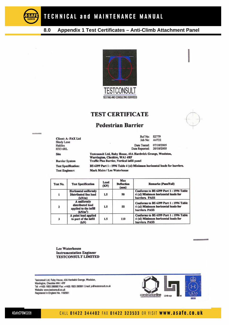
8.0 Appendix 1 Test Certificates – Anti-Climb Attachment Panel
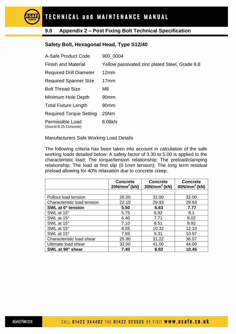
9.0 Appendix 2 – Post Fixing Bolt Technical Specification
Safety Bolt, Hexagonal Head, Type S12/40 A-Safe Product Code 900_0004
Finish and Material Yellow passivated zinc plated Steel, Grade 8.8
Required Drill Diameter 12mm
Required Spanner Size 17mm
Bolt Thread Size M8
Minimum Hole Depth 90mm
Total Fixture Length 90mm
Required Torque Setting 25Nm
Permissible Load 6.06kN (Sound B 25 Concrete)
Manufacturers Safe Working Load Details The following criteria has been taken into account in calculation of the safe working loads detailed below: A safety factor of 3.30 to 5.00 is applied to the characteristic load; The torque/tension relationship; The preload/clamping relationship; The load at first slip (0.1mm tension); The long term residual preload allowing for 40% relaxation due to concrete creep. Concrete
20N/mm2 (kN) Concrete
30N/mm2 (kN) Concrete
40N/mm2 (kN) Pullout load tension 26.00 32.00 32.00 Characteristic load tension 22.10 29.93 29.93 SWL at 0° tension 5.50 6.63 7.77 SWL at 15° 5.75 6.92 8.1 SWL at 15° 6.40 7.71 9.02 SWL at 15° 7.10 8.51 9.92 SWL at 15° 8.55 10.32 12.10 SWL at 15° 7.65 9.31 10.97 Characteristic load shear 25.90 31.22 36.57 Ultimate load shear 32.00 41.00 44.00 SWL at 90° shear 7.40 8.92 10.45

Accessories
Swing Gate
Slide Gate
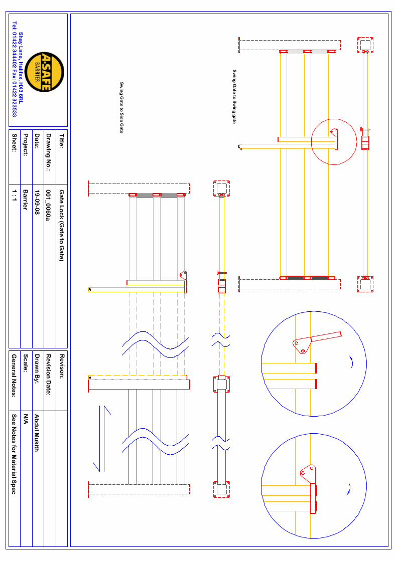
Gate Lock (Gate to Gate)
Gate Lock (Gate to Post)
Gate Stop (Post)
Gate Stop (Wall)
Sign Boards & signs
Kick Plates
Removable Barrier Slider Plates

C A L L 014 2 2 3 4 4 4 0 2 F A X 014 2 2 3 2 3 5 3 3 O R V I S I T www. a s a f e . c o . u k
A C C E S S O R I E S & A D D I T I O N A L P R O D U C T S
Access Gates . Signs . Height Restrictors . Rack Protectors . Kick Plates . Safety Matting . Micro Barriers . Base Plates
Access Gates•Compatible for use with Pedestrian Barrier, Handrail
and Traffic Barrier when fitted with Pedestrian RailAttachment
•Swing (Double action) and Sliding options•Standard opening sizes of 1000mm, 1500mm and
2000mm•Can be installed in pairs to give openings to a
maximum of 4000mm.•Can be installed as part of a barrier section or as a
stand-alone gate•Single swing gates can be mounted in-line with or at
right angles to a barrier section•Non-standard sizes are optionally availableOptions available for:•Indicating access points for fire exits, fire or safety
equipment or medical assistance. Gates supplied infire exit green
•Limiting a swing gate action to swing in onedirection only
•Securing gates in an open or closed position•Locking gates in a closed position
Health & Safety Signs & Signboards•Compatible for use with Pedestrian Barrier, Handrail
and Traffic Barrier when fitted with Pedestrian RailAttachment
•All signs accredited to ISO9001 - 2000•Signboards available for display of single or multiple
message signs and charts•Signs supplied in rigid plastic. Self adhesive signs are
optionally available.•Large standard range of commonly used signs•Customised signs available to meet specific symbol,
layout and text design requirementsFor prominent display in a necessary or desiredlocation of:•Prohibition, Hazard/Warning, Mandatory, Safe
Condition and Fire Equipment message signs•Health and Safety Rules and Regulations required to
be displayed by law•Company Rules and Regulations as required to be
displayed by Company Policy

Gate Lock (Gate to Gate)
Gate Lock (Gate to Post)
Gate Stop (Wall) Gate Stop (Post)

Removable Barrier Slider Plates


DescriptionPart Code
2
Hinge section metal parts
Gate section
Barrier post (not supplied with gate)
Central gate support
End gate support with nylon wheel
No
3
4
5
Next barrier section end post 6
1
3* 6Overall length
Post centre to post centre
1000mm Gate mounted to barrier post
3
NORTHSOUTH
WEST
EAST
BARRIER
Gate mounting position orientation convention.Where the gate is mounted to a 90°corner post thebarrier entry/exit is always South/East. Gate orientation can ONLY be North or West.
665
21
1160
Gate Opening5
43*
Overall length
1100
Gate larger than 1000mm mounted to barrier post
All dimensions shown in mm*Barrier post not supplied as part of the gate
Part Code Supports FittedDimensions
1000mm1500mm2000mm
1000-2000mm
1105mm1605mm2105mm
Opening + 105mm
1180mm1680mm2120mm
Opening + 180mm
Opening Overall Central End
No NoYes YesYes Yes
Yes Yes
010_0001010_0002010_0003
010_0004
Post centre to gate end
Post centre to post centre
T E C H N I C A L I N F O R M A T I O N
S w i n g G a t e D i m e n s i o n s
C A L L 0 14 2 2 3 4 4 4 0 2 F A X 0 14 2 2 3 2 3 5 3 3 O R V I S I T w w w . a s a f e . c o . u kASafeSwG0207


Overall gate length (closed)
Gate opening
1160
Barrier section
1107.5
1100 1160
1 4
2
NORTHSOUTH
WEST
EAST
BARRIER
DescriptionPart Code
2Gate barrier sectionGate sliding section Barrier post (not supplied with gate)
No
3Next barrier section end post4
1
All dimensions shown in mm* Post not supplied as part of gate barrier section
3*
3
3* 3
Part Gate Dimensions
1000mm1500mm2000mm
1000-2000mm
2205mm3205mm4205mm
2260mm3260mm4260mm
Opening Overall
1100mm1600mm2100mm
Barrier Section
010_0020010_0021010_0022
010_0023
Post centre to gate end
Post centre to post centre
Gate mounting position orientation convention.Where the gate is mounted to a 90° corner post thebarrier entry/exit is always South/East. Gateorientation can ONLY be North or West.
T E C H N I C A L I N F O R M A T I O N
S l i d i n g G a t e D i m e n s i o n s
C A L L 0 14 2 2 3 4 4 4 0 2 F A X 0 14 2 2 3 2 3 5 3 3 O R V I S I T w w w . a s a f e . c o . u kASafeSlG0308
Gate opening (x 2) +205mm
Gate opening +260mm
Gate opening +100mm


A C C E S S O R I E S & A D D I T I O N A L P R O D U C T S
Kick Plates•Compatible for use with Pedestrian Barrier and
Handrail
•To prevent low level access (eg FLT forks, hand pallet
trucks) passing under a barrier for protection of
walls, structures and equipment
•To prevent items (eg tools, equipment, goods) falling
from height when a barrier is installed along a raised
edge (eg mezzanine floor, loading bay)
•Not retrofittable, must be specified with relevant
barrier system at time of purchase
C A L L 014 2 2 3 4 4 4 0 2 F A X 014 2 2 3 2 3 5 3 3 O R V I S I T www. a s a f e . c o . u k
Kick Plates