Embed Size (px)
DESCRIPTION
COM 117 Introduction to Application Building. Introduction to the module Learning outcomes Assessment Lecture on DFDs Practical activity Tutorial activity. Assessment Strategy. Group project 60%. Assessment Strategy TCT on design techniques (multiple choice and short answer)20% - PowerPoint PPT Presentation
Citation preview

COM 117 Introduction to Application Building
• Introduction to the module
• Learning outcomes
• Assessment
• Lecture on DFDs
• Practical activity
• Tutorial activity

Assessment Strategy
• Assessment Strategy• TCT on design techniques
(multiple choice and short answer) 20%
• TCT lab test on further Access Database Skills20%
• Group project 60%••
Group project 60%• Good interface (Input/output design)
10%
• Modelled requirements’ documentation
20%
• Level of complexity and accuracy in application
30%
• Ease of use of system
10%
• Choice of sample data
10%
• Reports
10%
• Testing documentation
10%

Timetable
• http://osiris.sunderland.ac.uk/~cs0lhu/Lynne/com117.htm

Data Flow Diagrams

IntroductionSSADMWhat is a Data Flow Diagram?
Why do we use DFDs?Levelling ConventionsDecomposition and AbstractionThe Elements
Process and Data StoresExternal EntityData FlowThe LevelsRules

Constructing DFDs
The Document Flow DiagramThe Context Diagram
Draw the external entities and data stores
Level 1 Physical DFDExample: Hairdressing Salon Level
1 Physical DFDSummary

S.S.A.D.M.
• S.S.A.D.M. - Structured Systems Analysis and Design Method
• Uses different techniques to model a system– Data Flow Diagrams – Entity Relational Model (Logical Data
Stores)– Normalisation

What is a Data Flow Diagram?
• Known as DFDs
• A way to model a real world situation
• They model the real world situation which aids discussion and clarity amongst users, analysts and designers.

Why do we use DFDs?• It is a way of taking the physical view
and converting it into a logical view.• The physical view - all documents
involved• The logical view - the data they
contain• Their main purpose is to
communicate with the user, the analyst’s understanding of the scope of the required system

Levelling• Levels determine the amount of
information shown• Context diagrams show environment• Each level shows more info. than the last • DFDs are expanded or decomposed into
levels.• Separating each process into sub
processes• Uncovers more and more detail

ConventionsBalancing
Process at lower level should have identical data flows if they flow out of a process
Modelling Data Stores
Only use DATA STORES used within this process on the diagram
Numbering
1 - 1.1 - 1.1.1
1.2 - 1.2.1
Labels
Should carry as much meaning as possible

Decomposition and Abstraction
• Decomposition - Divide and subdivide into manageable size problems
• Abstraction - Concentrate on the important issues and ignore the irrelevant

The ElementsThe four main elements of DFDs notation
Data Flows, with a label to indicate what data is flowing
Processes, that handle the data
Data stores, within the system (diary, filing cabinet or computer file)
External entities, outside sources of data

Process and Data Stores
A process is made up of
Data Stores
Process Number
Destination (Place or Name)
Process description Should be descriptive, starting with a verb.
M1
Can be M for manual or D for computer base data stores.
Name of Store

External Entity
Is anything outside the system that is of interest to the system. Can be a person, a company or another system.Outside entity shows the Name and a lowercase alpha character is used to uniquely identify it.
If an outside entity is repeated for the purpose of neat layout a line is added across the top.
Customer a
Customer a

Data Flow
Is shown by a line with an arrowhead, indicating the direction of the flow of data.
Each data flow should be named to indicate what data is being passed.
Nouns or adjectives only no verbs are permitted.

The Levels• Context - Overview - contains only one
process• Level 1 - Utilises all four elements• Level 2 - A breakdown of a level 1 process• Level 3 - A breakdown of a level 2 process• There is no rule as to how many levels of
DFD that can be used.

RulesSequence not important - getting the
Process correct is• Context or Level 0 - Identifies the
system/ boundary/External Links• Level 1 - Overview of function• Level 2 - Breakdown to Understand
Hard to know where to stopRule of ThumbIf there are more than 8 data flows
break itProcess of Identifying major
Processes
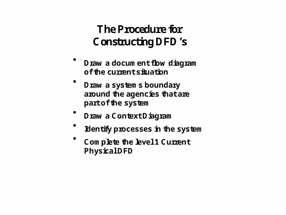
The Procedure forConstructing DFD’s
Draw a document flow diagramof the current situation
Draw a systems boundaryaround the agencies that arepart of the system
Draw a Context Diagram
Identify processes in the system
Complete the level 1 CurrentPhysical DFD

The Document Flow Diagram
The task of modelling a business situation can be daunting at first. Itis best to start with something simple such as a document flowdiagram.
Production Planning
Stock Control
FactoryDesign
Purchasing
Supplier
Stock
NoteWithdrawal
Production Plan Purchase
Order
Delivery Note
Material Requirements List
Bill ofMaterials
Supplier Details Update Form
DeliveryNote

The Context Diagram
You decide which agencies are to be part of the system thatyou are examining.
These agencies fall inside the system boundary and arereduced to one box in the centre.
This is a Context Diagram
Production Planning
Stock Control
Factory
Design Purchasing
Supplier
Stock
NoteWithdrawal
Production Plan
Delivery Note
Material Requirements List
Bill of Materials
Supplier Details Update Form
DeliveryNote
MaintainStock System
a b
c
d
e
(Lejk & Deeks)

All data flows going into the system must be received by a process. All data flows going out of the system must be generated by process. The first task is therefore to identify these processes:
Stock clerk
Maintain
1
2
3
Stock clerk
Stock clerk
planned call-off
Maintainstock cards
Preparematerial reqmnts
list
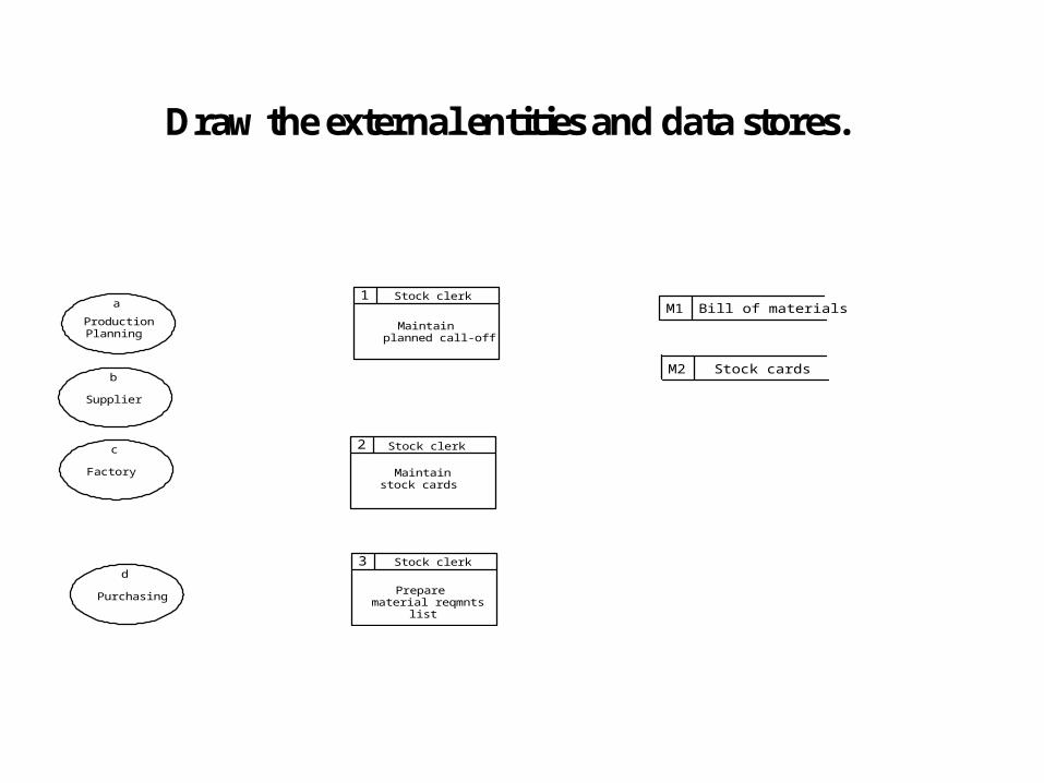
Draw the external entities and data stores.
Production
Stock clerk
Maintain
a Bill of materialsM11
2
3
Stock clerk
Stock cardsM2
Stock clerk
planned call-off
Maintainstock cards
Preparematerial reqmnts
list
Planning
Supplier
b
Factory
c
Purchasing
d

Level 1 Physical DFD - Complete
Finally draw in the data flows to give acompleted diagram. Note that a data flow musthave a process at the end .
Production
Stock clerk
Maintain
a Bill of materialsM11
2
3
Stock clerk
Stock cardsM2
Delivery note
B O M details
Planned call-off
details
Stock details
Stock clerk
planned call-off
Maintainstock cards
Preparematerial reqmnts
list
Planning
Production
Plan
Supplier
b
Factory
c
Stock withdrawal note
Purchasing
d
Material requirementslist
Updated supply details
Deliverynote
Stock details
(Lejk & Deeks)

Hairdressing Salon Level 1Physical DFD
Client
Receptionist
Register
a
Client card indexM1
1
Confirm
2
Hairdresser/Rcptnst
Conduct
3
arrival
Receptionist
Appointment
Appointment diaryM2
appointment
Appointmentdetails
Change ofhairstyle etc.
Appointmentdetails Confirmation
Request
ConfirmationDetails
New clientdetails
Existing clientdetails
Appointmentdetails
Confirmation ofarrival
Change ofhairstyle etc.
Appointmentdetails
(Lejk & Deeks)
(Lejk & Deeks)

Process 3 Level 2
3 Hair/Reception
Cliea
Hair Details
Clienta
3.1 Hairdresser
Conduct Appointment
3.2 Hairdresser
Inform Reception
3.3 Receptionist
Complete Appointment
M2 Diary
Appointment Details
M3 Client Card
Change of Hair Details

Naming of DFD processesLevel 0 Level 1 Level 2 Level 3 Level 4
Client
OverallProcess
Client
Process
Process
Process
1
2
3
2
2.1
2.2
2.3
SubProcess
SubProcess
SubProcess
SubProcessSubProcess
Process
2.2
Sub - SubProcess
2.1.1
2.1.2
Sub - SubProcess
Elementaryprocessdescriptions.
Decision treesDecision tableStructuredEnglish
2.1.1
There must be consistency between levels, with allthe data appearing on the higher level DFD. If a datastore is used only for one process it is placed withthat process. Outside entities are always shownoutside the boundary of a lower level DFD process,even if they only communicate with that one process.

What happens if part of the system is on computer?
• Electronic datastores • The above example was based on a manual system. If
the datastores are computer records rather than manual files the convention is to label the datastore D1, D2 etc.
D1

Summary
SSADMWhat a DFD is & Why we use themThe conventionsWhat the elements are