Embed Size (px)
Citation preview
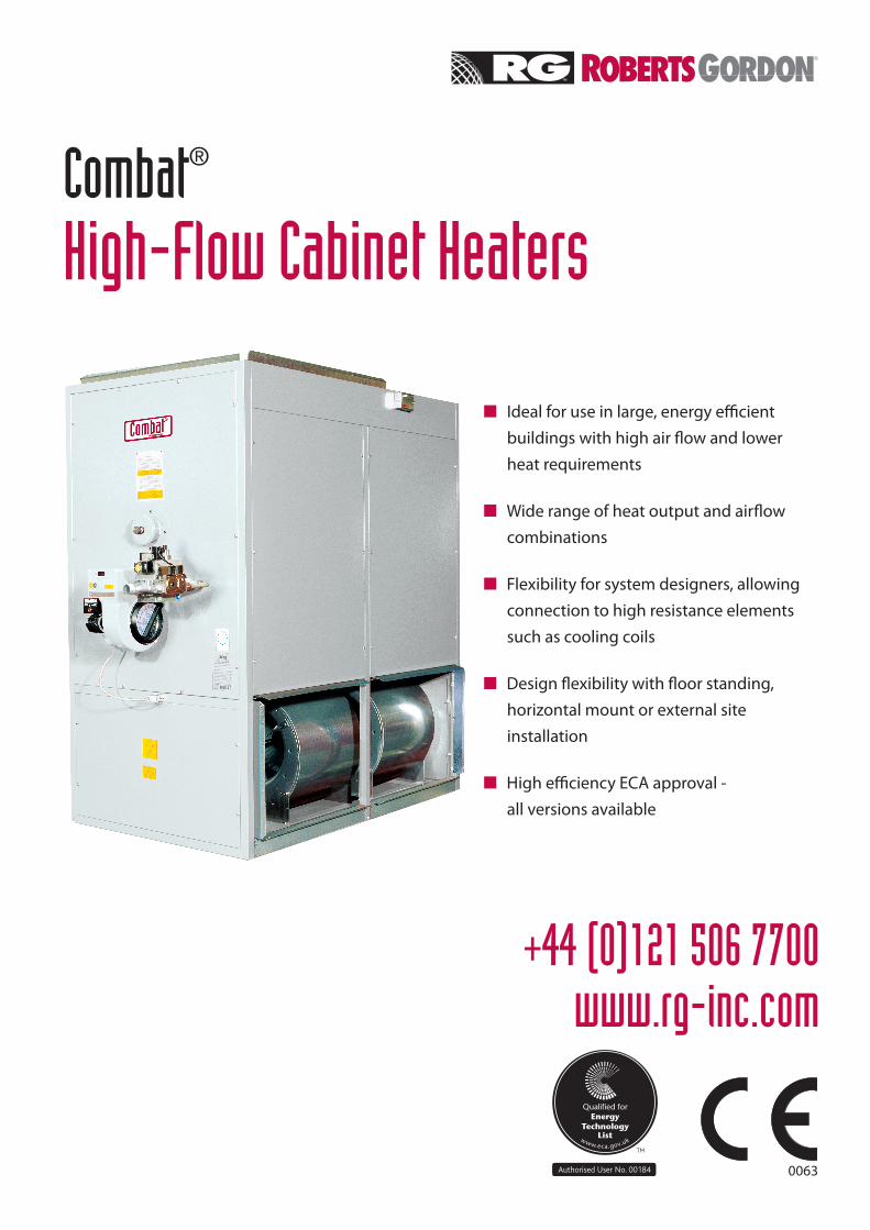
Combat®
High-Flow Cabinet Heaters
+44 (0)121 506 7700www.rg-inc.com
n Ideal for use in large, energy efficient buildings with high air flow and lower heat requirements
nWide range of heat output and airflow combinations
nFlexibility for system designers, allowing connection to high resistance elements such as cooling coils
nDesign flexibility with floor standing, horizontal mount or external site installation
nHigh efficiency ECA approval - all versions available
0063
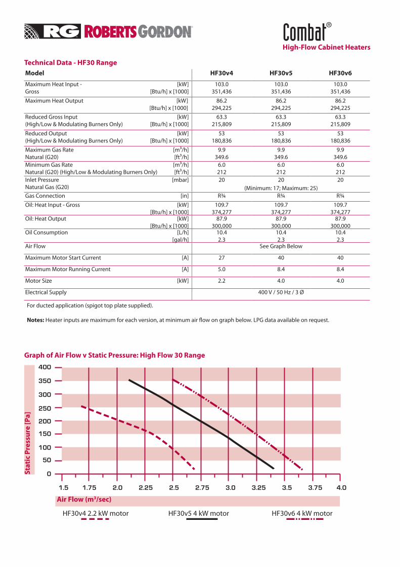
Technical Data - HF30 RangeModel HF30v4 HF30v5 HF30v6
Maximum Heat Input - [kW] Gross [Btu/h] x [1000]
103.0351,436
103.0351,436
103.0351,436
Maximum Heat Output [kW] [Btu/h] x [1000]
86.2294,225
86.2294,225
86.2294,225
Reduced Gross Input [kW] (High/Low & Modulating Burners Only) [Btu/h] x [1000]
63.3215,809
63.3215,809
63.3215,809
Reduced Output [kW] (High/Low & Modulating Burners Only) [Btu/h] x [1000]
53180,836
53180,836
53180,836
Maximum Gas Rate [m³/h] Natural (G20) [ft³/h]
9.9349.6
9.9349.6
9.9349.6
Minimum Gas Rate [m³/h] Natural (G20) (High/Low & Modulating Burners Only) [ft³/h]
6.0212
6.0212
6.0212
Inlet Pressure [mbar] Natural Gas (G20)
20 20 20(Minimum: 17; Maximum: 25)
Gas Connection [in] R¾ R¾ R¾
Oil: Heat Input - Gross [kW] [Btu/h] x [1000]
109.7374,277
109.7374,277
109.7374,277
Oil: Heat Output [kW] [Btu/h] x [1000]
87.9300,000
87.9300,000
87.9300,000
Oil Consumption [L/h] [gal/h]
10.42.3
10.42.3
10.42.3
Air Flow See Graph Below
Maximum Motor Start Current [A] 27 40 40
Maximum Motor Running Current [A] 5.0 8.4 8.4
Motor Size [kW] 2.2 4.0 4.0
Electrical Supply 400 V / 50 Hz / 3 Ø
For ducted application (spigot top plate supplied).
Notes: Heater inputs are maximum for each version, at minimum air flow on graph below. LPG data available on request.
Combat®
High-Flow Cabinet Heaters
Graph of Air Flow v Static Pressure: High Flow 30 Range
Stat
ic P
ress
ure
[Pa]
Air Flow (m3/sec)
HF30v4 2.2 kW motor HF30v5 4 kW motor HF30v6 4 kW motor
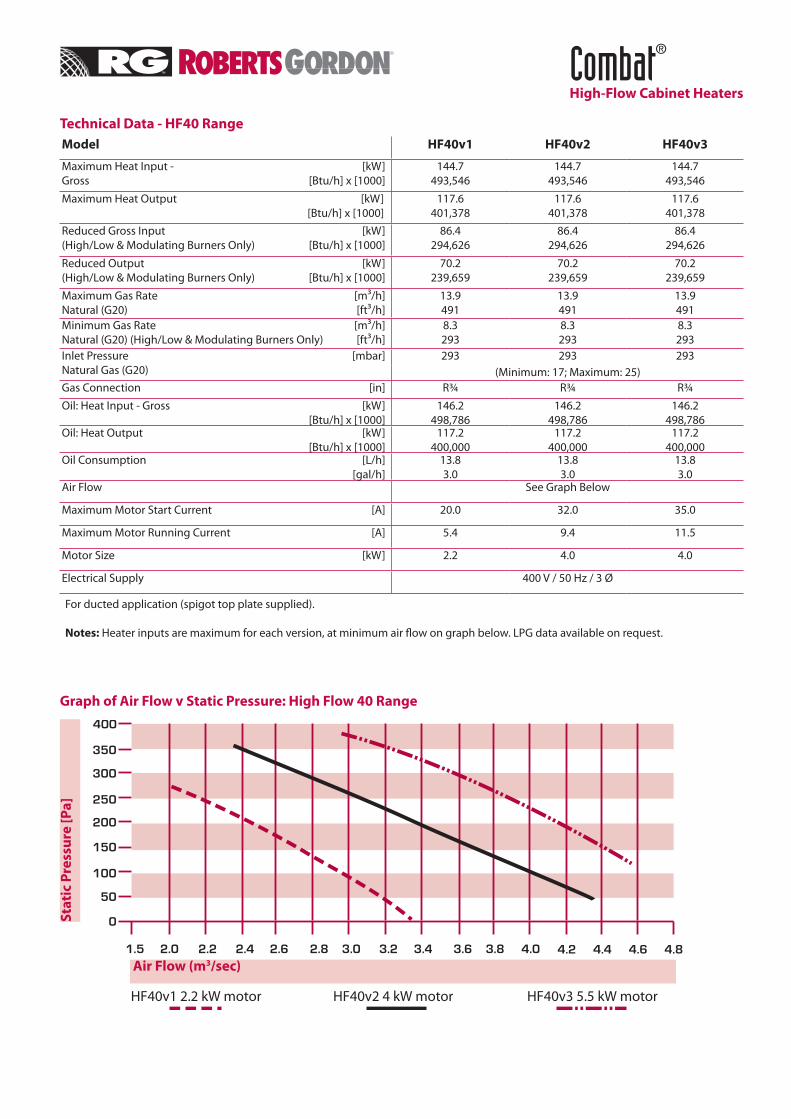
Technical Data - HF40 RangeModel HF40v1 HF40v2 HF40v3
Maximum Heat Input - [kW] Gross [Btu/h] x [1000]
144.7493,546
144.7493,546
144.7493,546
Maximum Heat Output [kW] [Btu/h] x [1000]
117.6401,378
117.6401,378
117.6401,378
Reduced Gross Input [kW] (High/Low & Modulating Burners Only) [Btu/h] x [1000]
86.4294,626
86.4294,626
86.4294,626
Reduced Output [kW] (High/Low & Modulating Burners Only) [Btu/h] x [1000]
70.2239,659
70.2239,659
70.2239,659
Maximum Gas Rate [m³/h] Natural (G20) [ft³/h]
13.9491
13.9491
13.9491
Minimum Gas Rate [m³/h] Natural (G20) (High/Low & Modulating Burners Only) [ft³/h]
8.3293
8.3293
8.3293
Inlet Pressure [mbar] Natural Gas (G20)
293 293 293(Minimum: 17; Maximum: 25)
Gas Connection [in] R¾ R¾ R¾
Oil: Heat Input - Gross [kW] [Btu/h] x [1000]
146.2498,786
146.2498,786
146.2498,786
Oil: Heat Output [kW] [Btu/h] x [1000]
117.2400,000
117.2400,000
117.2400,000
Oil Consumption [L/h] [gal/h]
13.83.0
13.83.0
13.83.0
Air Flow See Graph Below
Maximum Motor Start Current [A] 20.0 32.0 35.0
Maximum Motor Running Current [A] 5.4 9.4 11.5
Motor Size [kW] 2.2 4.0 4.0
Electrical Supply 400 V / 50 Hz / 3 Ø
For ducted application (spigot top plate supplied).
Notes: Heater inputs are maximum for each version, at minimum air flow on graph below. LPG data available on request.
Combat®
High-Flow Cabinet Heaters
Graph of Air Flow v Static Pressure: High Flow 40 Range
Stat
ic P
ress
ure
[Pa]
Air Flow (m3/sec)
HF40v1 2.2 kW motor HF40v2 4 kW motor HF40v3 5.5 kW motor
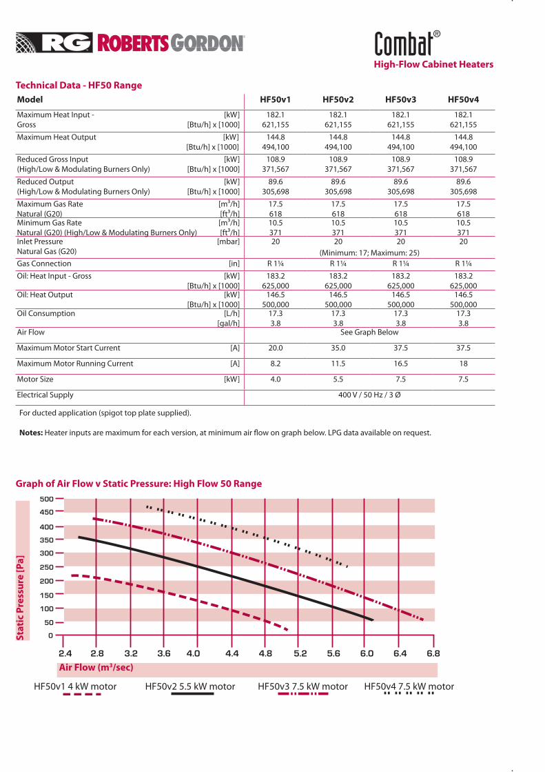
Technical Data - HF50 RangeModel HF50v1 HF50v2 HF50v3 HF50v4
Maximum Heat Input - [kW] Gross [Btu/h] x [1000]
182.1621,155
182.1621,155
182.1621,155
182.1621,155
Maximum Heat Output [kW] [Btu/h] x [1000]
144.8494,100
144.8494,100
144.8494,100
144.8494,100
Reduced Gross Input [kW] (High/Low & Modulating Burners Only) [Btu/h] x [1000]
108.9371,567
108.9371,567
108.9371,567
108.9371,567
Reduced Output [kW] (High/Low & Modulating Burners Only) [Btu/h] x [1000]
89.6305,698
89.6305,698
89.6305,698
89.6305,698
Maximum Gas Rate [m³/h] Natural (G20) [ft³/h]
17.5618
17.5618
17.5618
17.5618
Minimum Gas Rate [m³/h] Natural (G20) (High/Low & Modulating Burners Only) [ft³/h]
10.5371
10.5371
10.5371
10.5371
Inlet Pressure [mbar] Natural Gas (G20)
20 20 20 20(Minimum: 17; Maximum: 25)
Gas Connection [in] R 1¼ R 1¼ R 1¼ R 1¼
Oil: Heat Input - Gross [kW] [Btu/h] x [1000]
183.2625,000
183.2625,000
183.2625,000
183.2625,000
Oil: Heat Output [kW] [Btu/h] x [1000]
146.5500,000
146.5500,000
146.5500,000
146.5500,000
Oil Consumption [L/h] [gal/h]
17.33.8
17.33.8
17.33.8
17.33.8
Air Flow See Graph Below
Maximum Motor Start Current [A] 20.0 35.0 37.5 37.5
Maximum Motor Running Current [A] 8.2 11.5 16.5 18
Motor Size [kW] 4.0 5.5 7.5 7.5
Electrical Supply 400 V / 50 Hz / 3 Ø
For ducted application (spigot top plate supplied).
Notes: Heater inputs are maximum for each version, at minimum air flow on graph below. LPG data available on request.
Combat®
High-Flow Cabinet Heaters
Graph of Air Flow v Static Pressure: High Flow 50 Range
Stat
ic P
ress
ure
[Pa]
Air Flow (m3/sec)
HF50v1 4 kW motor HF50v2 5.5 kW motor HF50v3 7.5 kW motor HF50v4 7.5 kW motor
Combat®
High-Flow Cabinet Heaters
ControlsCombat® High-Flow cabinet heaters are designed to be operated with external controls and are fitted with electrical terminals to accommodate these.
Burner Options COMBAT® High-Flow cabinet heaters are fitted On/Off burners as standard. High/Low burners are available as an option on all models, and a fully modulating burner is available as an option on all Natural Gas and LPG fired models.
Inlet & Outlet Ducts Where there is a need for the heater to be connected to fresh air or air from an adjacent area for its intake of distribution air, inlet duct connections can be provided. Note: Supply air inlet connections can be made from either side, but not from the front or rear of the heater. When employing an inlet duct arrangement, there must be adequate provision for the supply of combustion air. Please contact Roberts-Gordon for advice. High-Flow cabinet heaters are fitted with an air outlet spigot fitted as standard.
FuelCombat® High-Flow cabinet heaters are designed for use on either: Natural Gas (G20), Propane (G31), Butane (G30), or Oil (Class D fuel oil to BS2869 (35 sec Redwood No .1).
Oil Connection KitFor all oil fired heaters, an oil line connection kit comprising of a gate valve, spring operated fire valve, oil filter and connecting nipples are required for installation on site.
Important NoticeThe equipment described in this Data Sheet is suitable for most commercial and industrial heating applications. However, in certain environments, particularly where there is a chlorinated atmosphere (e.g. near degreasing plant or other solvent processes), or a particularly dusty atmosphere, specialist advice should be sought at the design stage. Please consult Roberts-Gordon.
Roberts-Gordon reserves the right to alter product specification details without notice.
Installation Code and Annual Inspections: All installations and service of ROBERTS GORDON® equipment must be performed by a contractor qualified in the installation and service of equipment sold and supplied by Roberts-Gordon and conform to all requirements set forth in the ROBERTS GORDON® manuals and all applicable governmental authorities pertaining to the installation, service and operation of the equipment. To help facilitate optimum performance and safety, Roberts-Gordon recommends that a qualified contractor con-duct, at a minimum, annual inspections of your ROBERTS GORDON® equipment and perform service where necessary, using only replacement parts sold and supplied by Roberts-Gordon.Further Information: Applications, engineering and detailed guidance on systems design, installation and equipment performance is available through ROBERTS GORDON® representatives. Please contact us for any further information you may require, including the Installation, Operation and Service Manual.This product is not for residential use.This document is intended to assist licensed professionals in the exercise of their professional judgement.
COMBAT® High-Flow Cabinet Heaters are high efficiency heaters and are listed on the Enhanced Capital Allowance Scheme ‘Energy Technology Product List’. The ETL symbol is a UK registered certification mark of the carbon trust.
Combat®
High-Flow Cabinet Heaters
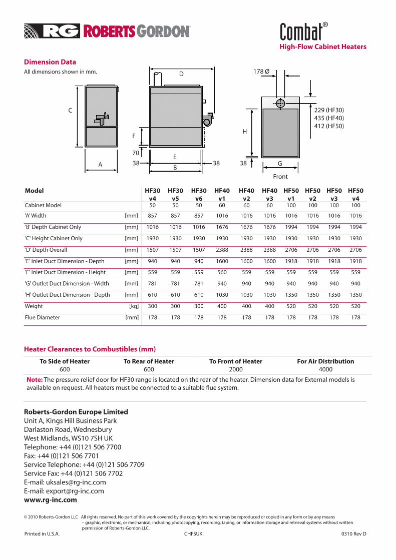
Dimension DataAll dimensions shown in mm.
Roberts-Gordon Europe LimitedUnit A, Kings Hill Business ParkDarlaston Road, WednesburyWest Midlands, WS10 7SH UKTelephone: +44 (0)121 506 7700Fax: +44 (0)121 506 7701Service Telephone: +44 (0)121 506 7709Service Fax: +44 (0)121 506 7702E-mail: [email protected]: [email protected]
© 2010 Roberts-Gordon LLC All rights reserved. No part of this work covered by the copyrights herein may be reproduced or copied in any form or by any means – graphic, electronic, or mechanical, including photocopying, recording, taping, or information storage and retrieval systems without written permission of Roberts-Gordon LLC.Printed in U.S.A. CHFSUK 0310 Rev D
Heater Clearances to Combustibles (mm)
To Side of Heater 600
To Rear of Heater 600
To Front of Heater 2000
For Air Distribution 4000
Note: The pressure relief door for HF30 range is located on the rear of the heater. Dimension data for External models is available on request. All heaters must be connected to a suitable flue system.
Model HF30v4
HF30v5
HF30v6
HF40v1
HF40v2
HF40v3
HF50v1
HF50v2
HF50v3
HF50v4
Cabinet Model 50 50 50 60 60 60 100 100 100 100
'A' Width [mm] 857 857 857 1016 1016 1016 1016 1016 1016 1016
'B' Depth Cabinet Only [mm] 1016 1016 1016 1676 1676 1676 1994 1994 1994 1994
'C' Height Cabinet Only [mm] 1930 1930 1930 1930 1930 1930 1930 1930 1930 1930
'D' Depth Overall [mm] 1507 1507 1507 2388 2388 2388 2706 2706 2706 2706
'E' Inlet Duct Dimension - Depth [mm] 940 940 940 1600 1600 1600 1918 1918 1918 1918
'F' Inlet Duct Dimension - Height [mm] 559 559 559 560 559 559 559 559 559 559
'G' Outlet Duct Dimension - Width [mm] 781 781 781 940 940 940 940 940 940 940
'H' Outlet Duct Dimension - Depth [mm] 610 610 610 1030 1030 1030 1350 1350 1350 1350
Weight [kg] 300 300 300 400 400 400 520 520 520 520
Flue Diameter [mm] 178 178 178 178 178 178 178 178 178 178
C
AE
D
FH
G
Front
229 (HF30)435 (HF40)412 (HF50)
70
178 Ø
38 38 38B