Embed Size (px)
Citation preview
1
Florida Combating Roadway Departures & Roadside Safety Design Workshop – Day 3
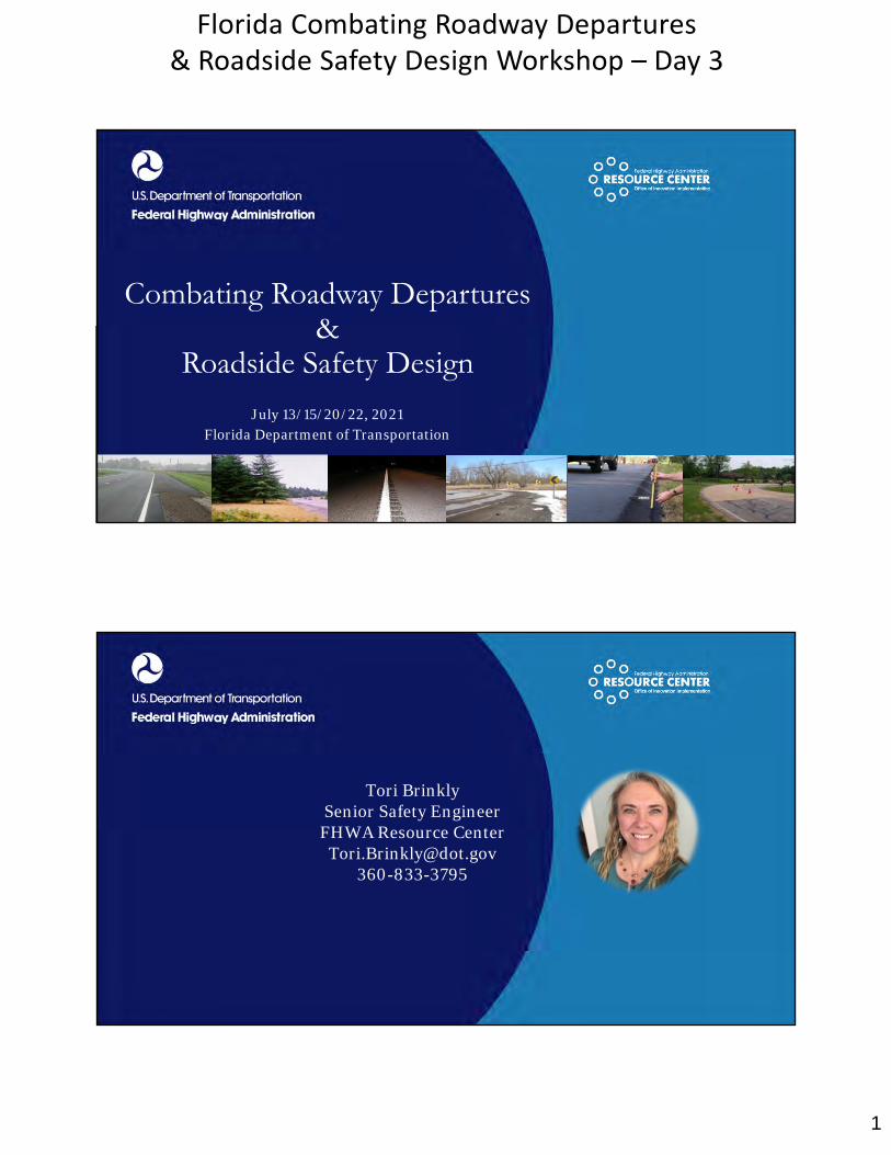
Combating Roadway Departures &
Roadside Safety Design
July 13/15/20/22, 2021Florida Department of Transportation
Tori BrinklySenior Safety EngineerFHWA Resource Center
2
Florida Combating Roadway Departures & Roadside Safety Design Workshop – Day 3
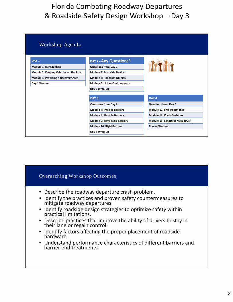
Workshop Agenda
DAY 1
Module 1: Introduction
Module 2: Keeping Vehicles on the Road
Module 3: Providing a Recovery Area
Day 1 Wrap‐up
DAY 2 –Any Questions?Questions from Day 1
Module 4: Roadside Devices
Module 5: Roadside Objects
Module 6: Urban Environments
Day 2 Wrap‐up
DAY 3
Questions from Day 2
Module 7: Intro to Barriers
Module 8: Flexible Barriers
Module 9: Semi‐Rigid Barriers
Module 10: Rigid Barriers
Day 3 Wrap‐up
DAY 4
Questions from Day 3
Module 11: End Treatments
Module 12: Crash Cushions
Module 13: Length of Need (LON)
Course Wrap‐up
Overarching Workshop Outcomes
• Describe the roadway departure crash problem.• Identify the practices and proven safety countermeasures tomitigate roadway departures.
• Identify roadside design strategies to optimize safety withinpractical limitations.
• Describe practices that improve the ability of drivers to stay intheir lane or regain control.
• Identify factors affecting the proper placement of roadsidehardware.
• Understand performance characteristics of different barriers andbarrier end treatments.
3
Florida Combating Roadway Departures & Roadside Safety Design Workshop – Day 3
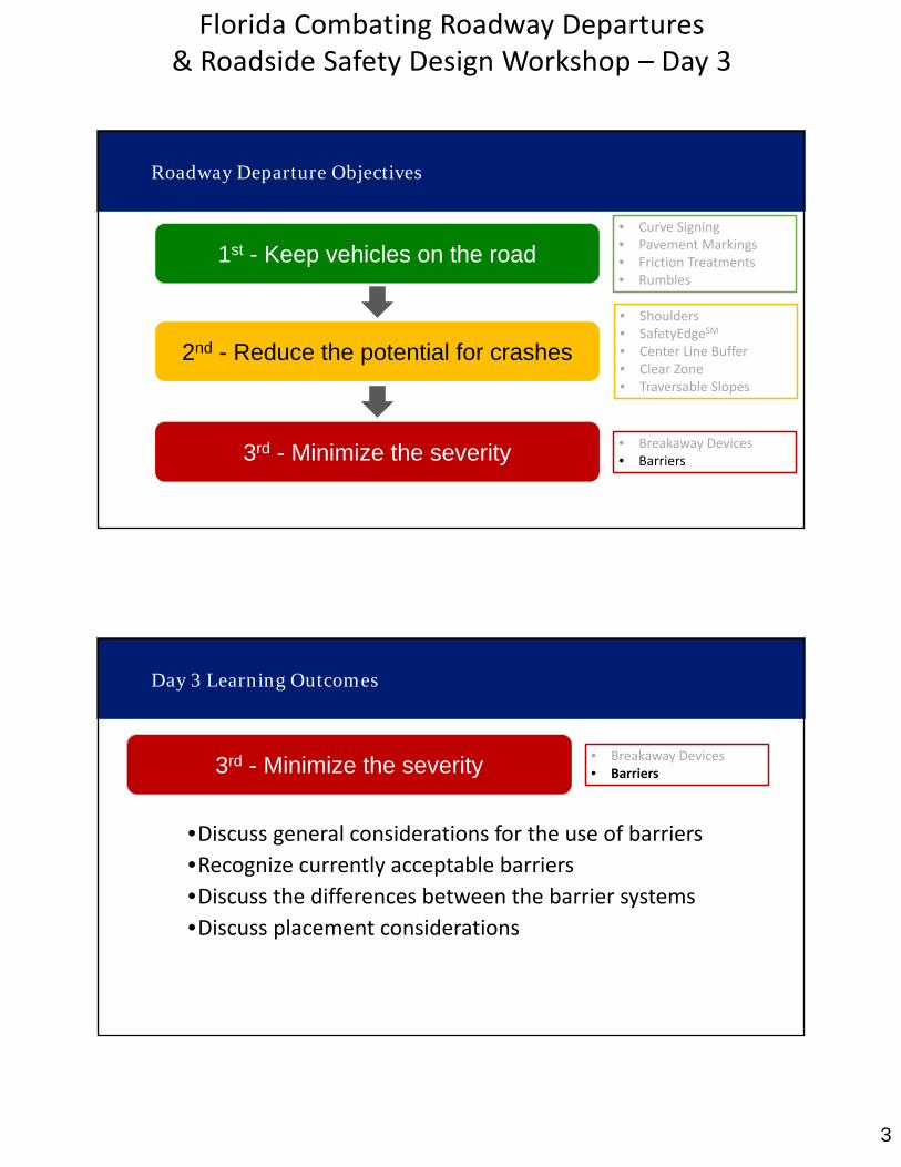
Roadway Departure Objectives
1st - Keep vehicles on the road
2nd - Reduce the potential for crashes
3rd - Minimize the severity
• Curve Signing• Pavement Markings• Friction Treatments• Rumbles
• Shoulders• SafetyEdgeSM
• Center Line Buffer• Clear Zone• Traversable Slopes
• Breakaway Devices• Barriers
Day 3 Learning Outcomes
•Discuss general considerations for the use of barriers•Recognize currently acceptable barriers•Discuss the differences between the barrier systems
•Discuss placement considerations
3rd - Minimize the severity • Breakaway Devices• Barriers

4
Florida Combating Roadway Departures & Roadside Safety Design Workshop – Day 3
Module 7
Introduction to Barriers
RDG Chapter 5 & 6
•REMOVE the obstacle
•REDESIGN the obstacle for safe traversal•RELOCATE the obstacle•REDUCE severity (make breakaway)
•SHIELD the obstacle•DELINEATE the obstacle
RDG Page 1‐4
Roadside Obstacle Mitigation

5
Florida Combating Roadway Departures & Roadside Safety Design Workshop – Day 3
Roadside Barriers
Barriers are fixed objects that can result in injuries or fatalities when hit.
Source: FARS 2017-2019
Poles/ Sign Posts
Barriers955 fatality/yr
Other Fixed Objects
The most common barriers systems are:• W‐beam guardrail• Concrete barriers• Cable barriers
Barriers are 12% of Fixed Object Fatalities
Trees
•Roadside Barriers
•Median Barriers
•Bridge Railings
Barrier Context
6
Florida Combating Roadway Departures & Roadside Safety Design Workshop – Day 3
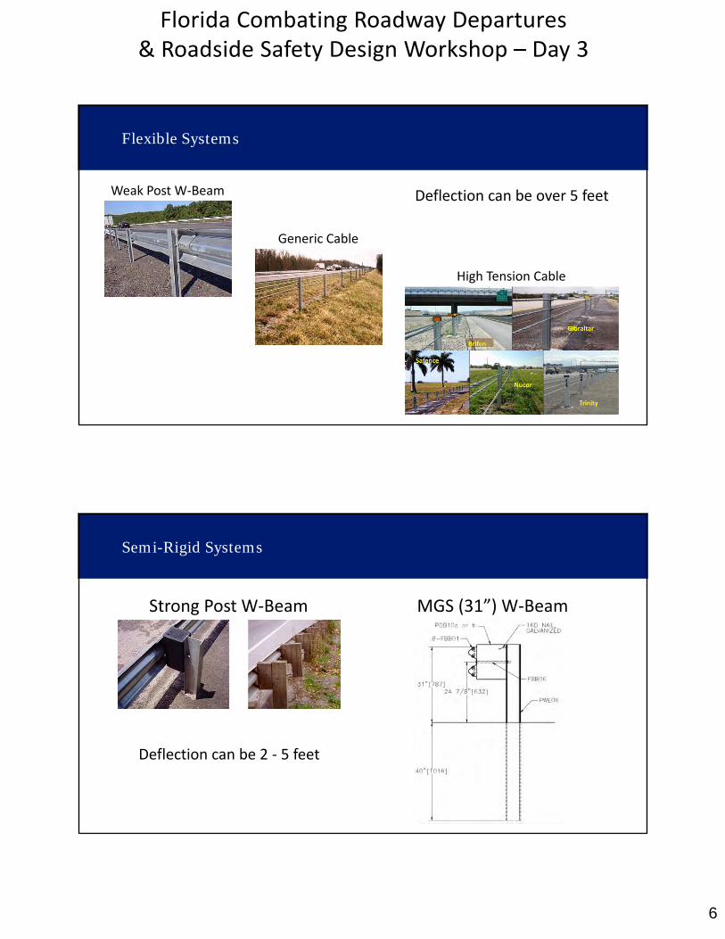
Flexible Systems
Weak Post W‐Beam
Generic Cable
High Tension Cable
Deflection can be over 5 feet
Strong Post W‐Beam
Semi-Rigid Systems
MGS (31”) W‐Beam
Deflection can be 2 ‐ 5 feet
7
Florida Combating Roadway Departures & Roadside Safety Design Workshop – Day 3
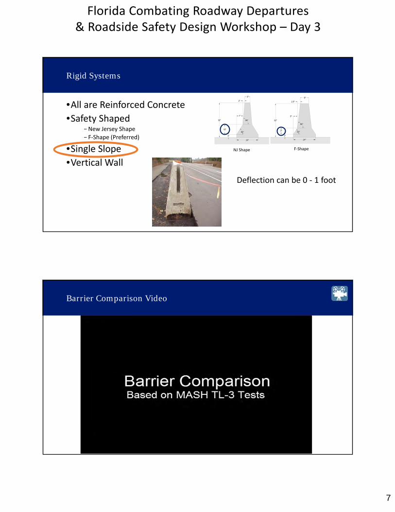
•All are Reinforced Concrete•Safety Shaped
−New Jersey Shape
− F‐Shape (Preferred)
•Single Slope•Vertical Wall
Rigid Systems
NJ Shape F‐Shape
Deflection can be 0 ‐ 1 foot
Barrier Comparison Video
8
Florida Combating Roadway Departures & Roadside Safety Design Workshop – Day 3
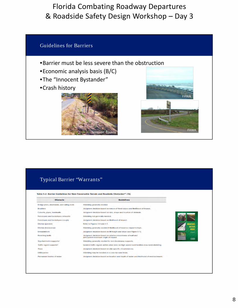
Simpson County
FHWA
Guidelines for Barriers
•Barrier must be less severe than the obstruction
•Economic analysis basis (B/C)
•The “Innocent Bystander”•Crash history
FHWA
Typical Barrier “Warrants”

9
Florida Combating Roadway Departures & Roadside Safety Design Workshop – Day 3
Typical Barrier “Warrants” – Bridge Piers
Typical Barrier “Warrants” – Large Culverts
10
Florida Combating Roadway Departures & Roadside Safety Design Workshop – Day 3
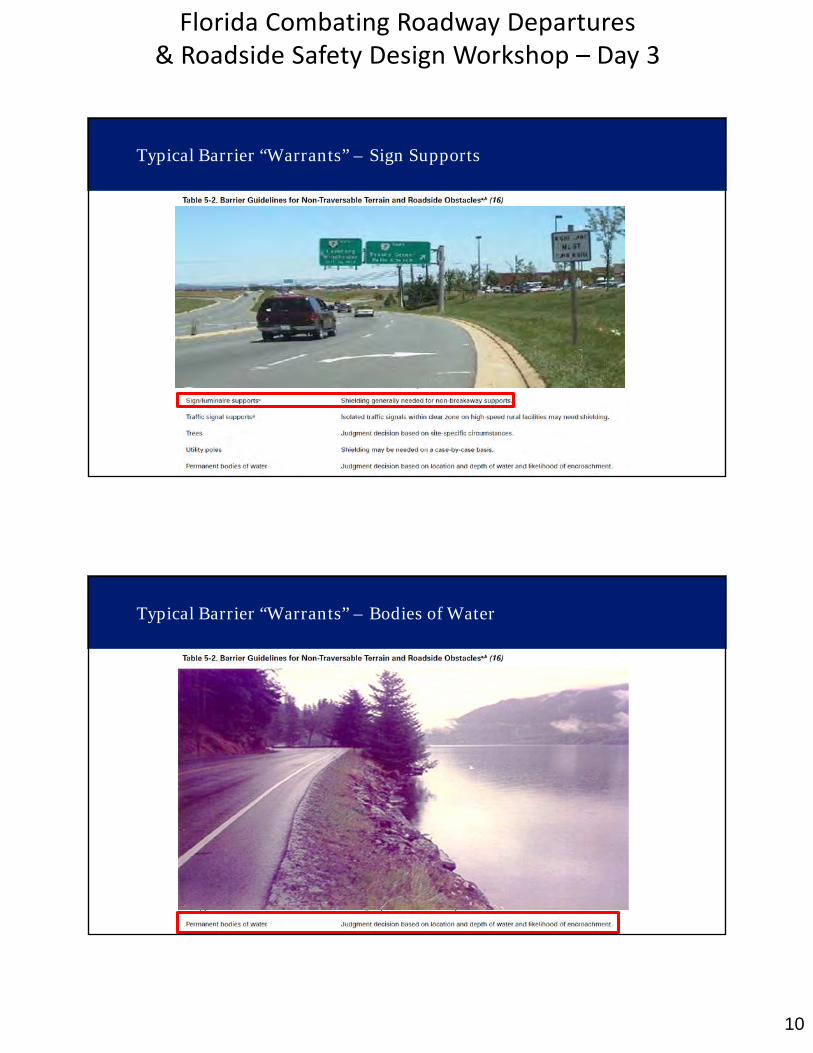
Typical Barrier “Warrants” – Sign Supports
Typical Barrier “Warrants” – Bodies of Water

11
Florida Combating Roadway Departures & Roadside Safety Design Workshop – Day 3
Typical Barrier “Warrants” - Embankment
Embankments – Comparative Risk
Basis for shielding embankment is
Comparative Risk: Slope risk vs. Barrier risk
RDG Figure 5‐1
12
Florida Combating Roadway Departures & Roadside Safety Design Workshop – Day 3
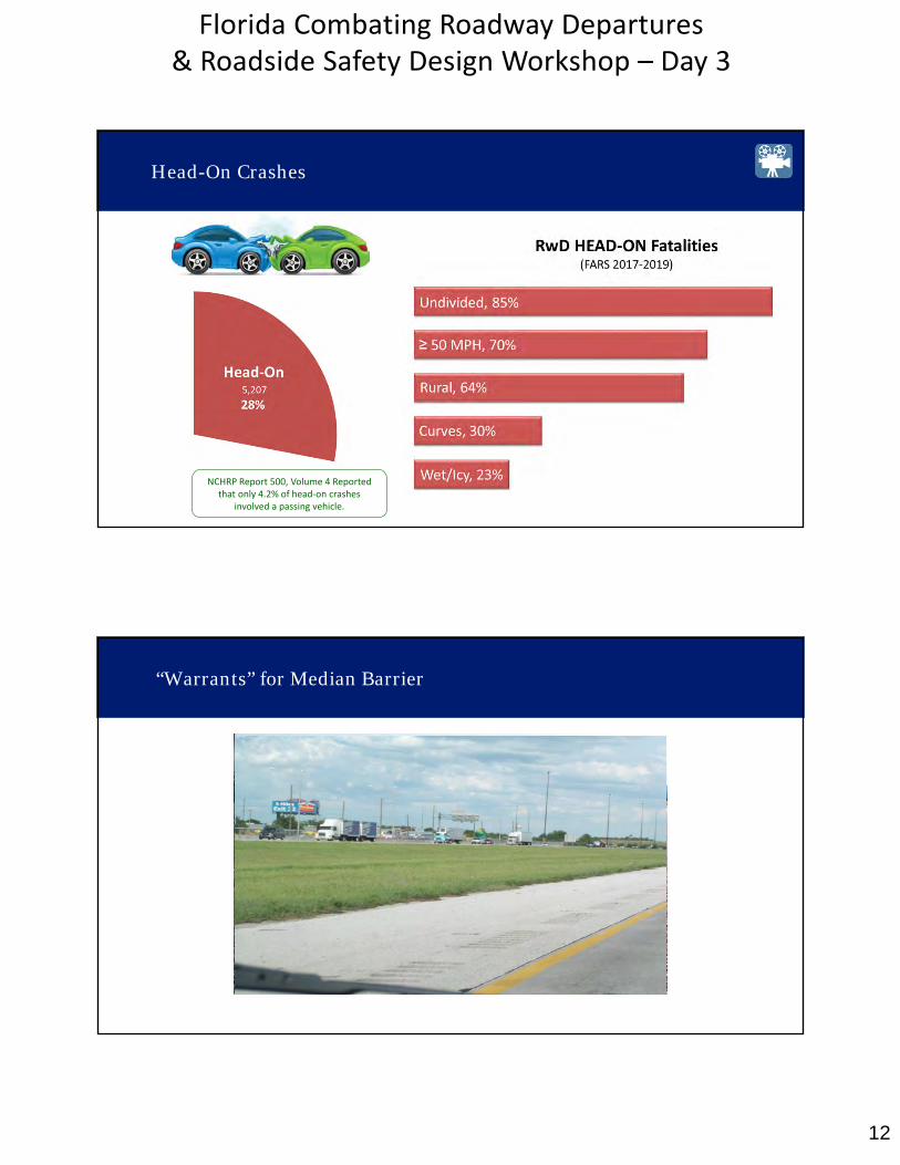
Head-On Crashes
NCHRP Report 500, Volume 4 Reported that only 4.2% of head‐on crashes
involved a passing vehicle.
“Warrants” for Median Barrier
13
Florida Combating Roadway Departures & Roadside Safety Design Workshop – Day 3
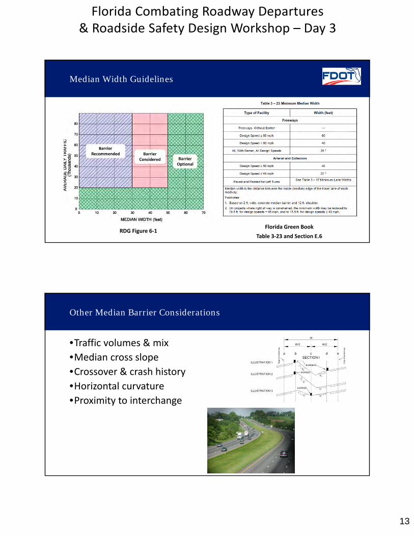
RDG Figure 6‐1
Median Width Guidelines
Florida Green Book
Table 3‐23 and Section E.6
•Traffic volumes & mix
•Median cross slope
•Crossover & crash history•Horizontal curvature•Proximity to interchange
Other Median Barrier Considerations
14
Florida Combating Roadway Departures & Roadside Safety Design Workshop – Day 3
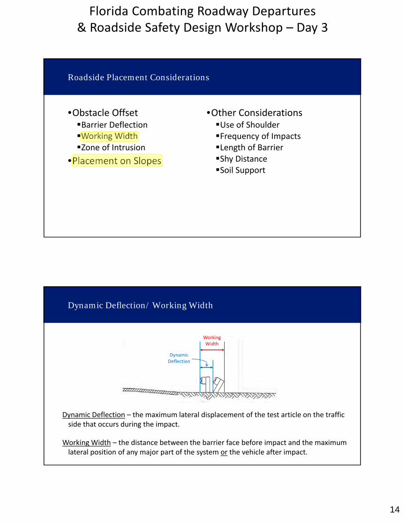
Roadside Placement Considerations
•Obstacle OffsetBarrier DeflectionWorking WidthZone of Intrusion
•Placement on Slopes
•Other ConsiderationsUse of ShoulderFrequency of ImpactsLength of BarrierShy DistanceSoil Support
Dynamic Deflection – the maximum lateral displacement of the test article on the traffic side that occurs during the impact.
DynamicDeflection
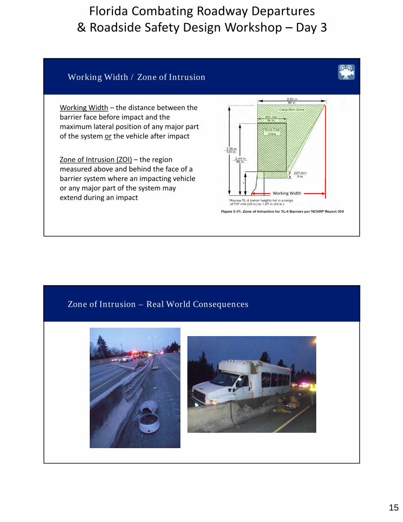
Working Width – the distance between the barrier face before impact and the maximum lateral position of any major part of the system or the vehicle after impact.
Working Width
Dynamic Deflection/ Working Width
15
Florida Combating Roadway Departures & Roadside Safety Design Workshop – Day 3
Zone of Intrusion (ZOI) – the region measured above and behind the face of a barrier system where an impacting vehicle or any major part of the system may extend during an impact Working Width
Zone of Intrusion
Working Width – the distance between the barrier face before impact and the maximum lateral position of any major part of the system or the vehicle after impact
Working Width
Working Width / Zone of Intrusion
Zone of Intrusion – Real World Consequences
16
Florida Combating Roadway Departures & Roadside Safety Design Workshop – Day 3
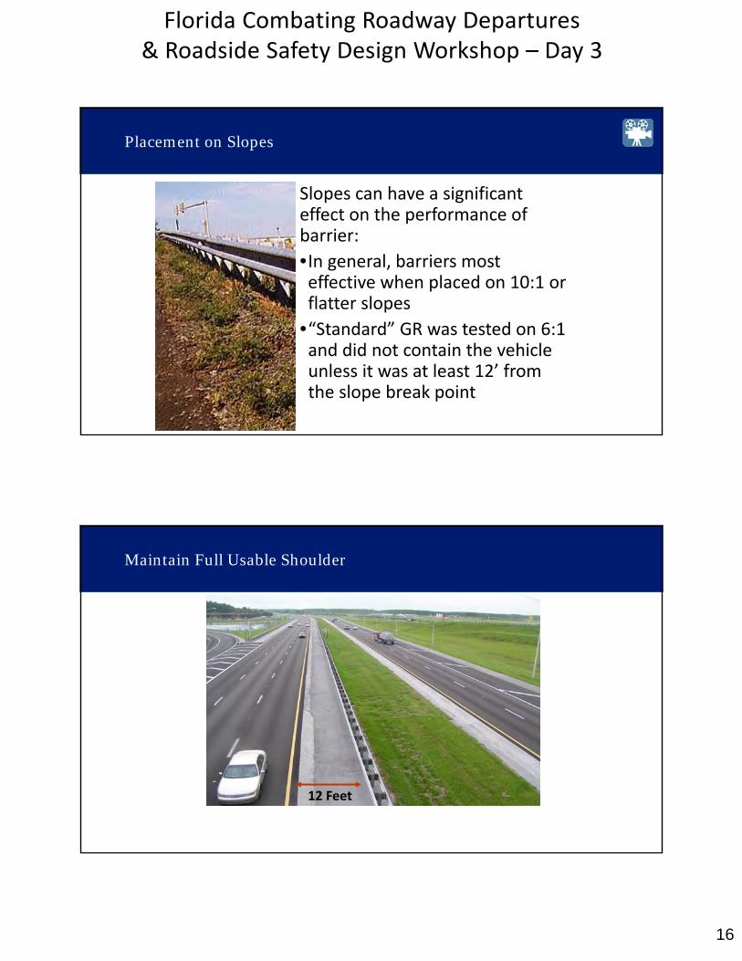
Placement on Slopes
Slopes can have a significant effect on the performance of barrier:
•In general, barriers mosteffective when placed on 10:1 orflatter slopes
•“Standard” GR was tested on 6:1 and did not contain the vehicle unless it was at least 12’ from the slope break point
12 Feet
Maintain Full Usable Shoulder

17
Florida Combating Roadway Departures & Roadside Safety Design Workshop – Day 3
•Discomfort may cause drivers to slow, shift lanes and position
•More of an issue on the right side
•Rule of Thumb: Place as far away from travel lane as practicalwithout affecting function
Shy Line Effect
Barrier Systems
Barrier systems include:
• Standard Sections
• End Treatments
• Transitions
It is important to ensure tension continuity throughout the system!
18
Florida Combating Roadway Departures & Roadside Safety Design Workshop – Day 3
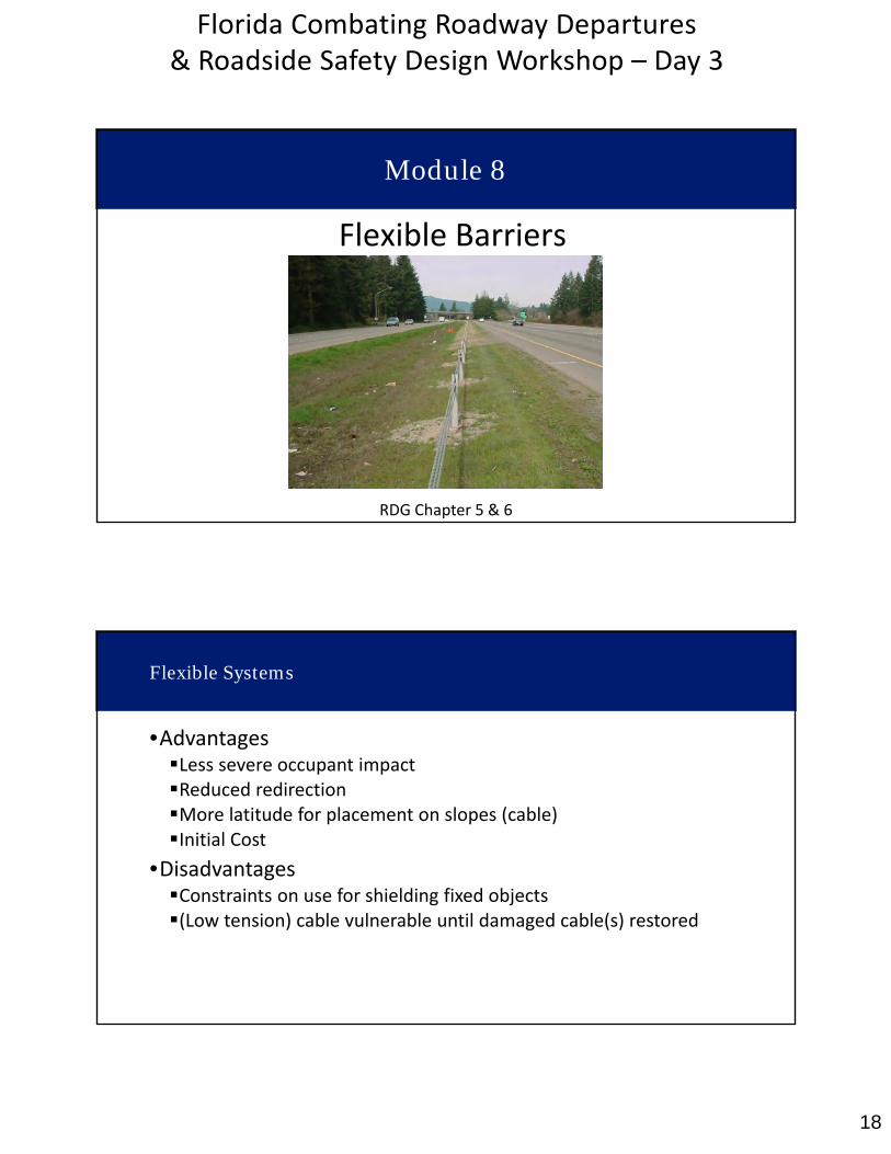
Module 8
Flexible Barriers
RDG Chapter 5 & 6
Flexible Systems
•AdvantagesLess severe occupant impactReduced redirectionMore latitude for placement on slopes (cable)Initial Cost
•DisadvantagesConstraints on use for shielding fixed objects(Low tension) cable vulnerable until damaged cable(s) restored
19
Florida Combating Roadway Departures & Roadside Safety Design Workshop – Day 3
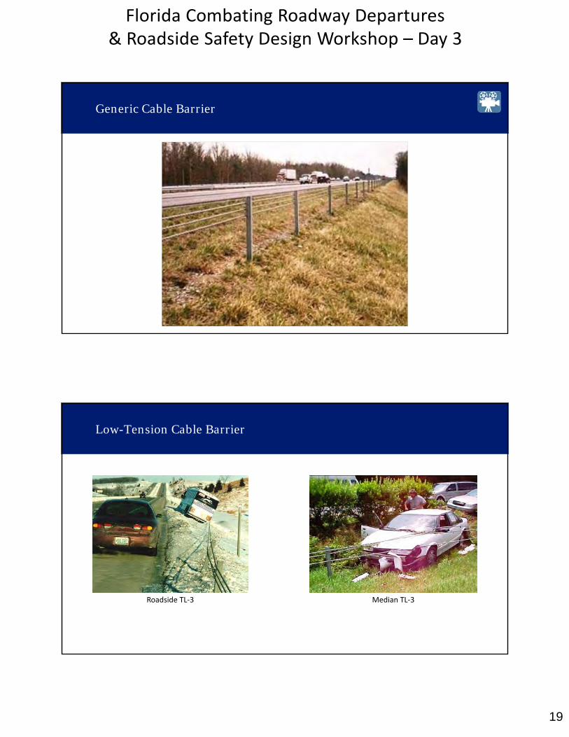
Generic Cable Barrier
Low-Tension Cable Barrier
Roadside TL‐3 Median TL‐3

20
Florida Combating Roadway Departures & Roadside Safety Design Workshop – Day 3
High-Tension Cable Systems
TL‐3 Low Tension 3 StrandI‐26 South Carolina
TL‐4Nucor High TensionI‐10 Louisiana
High Tension vs Low Tension Cable Barrier
21
Florida Combating Roadway Departures & Roadside Safety Design Workshop – Day 3
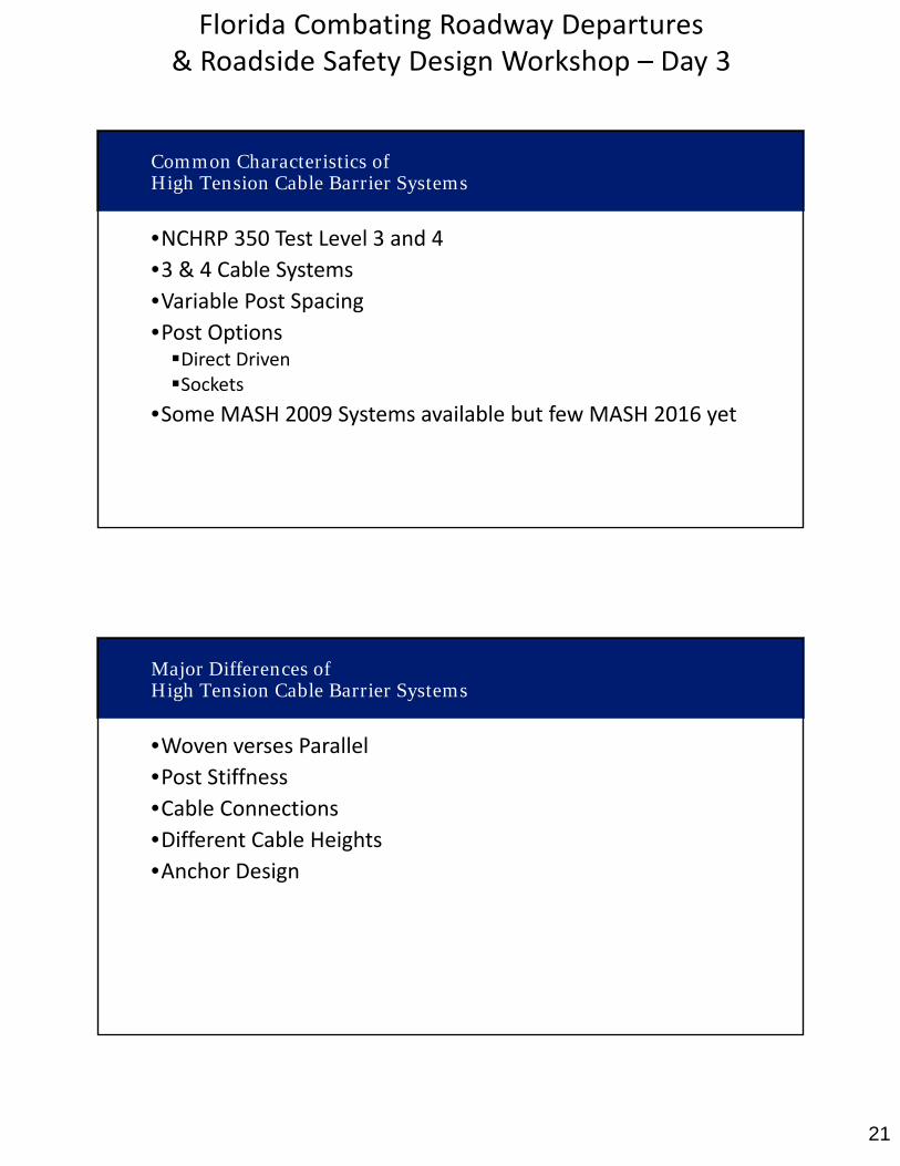
•NCHRP 350 Test Level 3 and 4•3 & 4 Cable Systems
•Variable Post Spacing•Post OptionsDirect DrivenSockets
•Some MASH 2009 Systems available but few MASH 2016 yet
Common Characteristics of High Tension Cable Barrier Systems
Major Differences of High Tension Cable Barrier Systems
•Woven verses Parallel
•Post Stiffness•Cable Connections•Different Cable Heights•Anchor Design

22
Florida Combating Roadway Departures & Roadside Safety Design Workshop – Day 3
High Tension Cable Barrier and FDOT IPL
Brifen
http://brifenusa.com/
23
Florida Combating Roadway Departures & Roadside Safety Design Workshop – Day 3
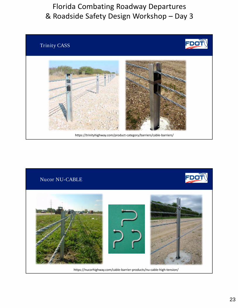
Trinity CASS
https://trinityhighway.com/product‐category/barriers/cable‐barriers/
Nucor NU-CABLE
https://nucorhighway.com/cable‐barrier‐products/nu‐cable‐high‐tension/
24
Florida Combating Roadway Departures & Roadside Safety Design Workshop – Day 3
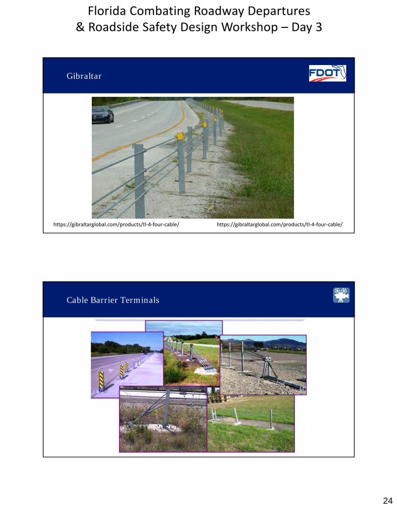
Gibraltar
https://gibraltarglobal.com/products/tl‐4‐four‐cable/https://gibraltarglobal.com/products/tl‐4‐four‐cable/
Cable Barrier Terminals

25
Florida Combating Roadway Departures & Roadside Safety Design Workshop – Day 3
Cable Barrier Terminals in Weak Soils
Barrier Performance Characteristics
•Design decisions that affect deflection, including placementin a curve
•Placement on slopes
•Dynamic design considerations to address barrierpenetration
•Which side of the median should the cable barrier be placed?
•Narrow median application
26
Florida Combating Roadway Departures & Roadside Safety Design Workshop – Day 3
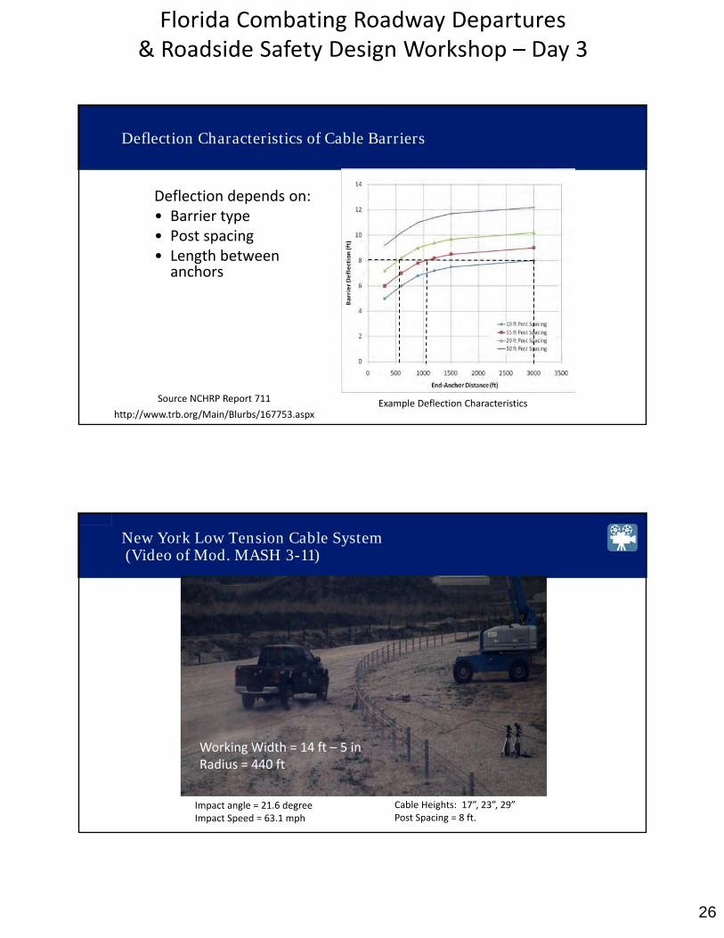
Example Deflection Characteristics
Deflection depends on:• Barrier type• Post spacing• Length betweenanchors
Source NCHRP Report 711
Deflection Characteristics of Cable Barriers
http://www.trb.org/Main/Blurbs/167753.aspx
New York Low Tension Cable System(Video of Mod. MASH 3-11)
Impact angle = 21.6 degreeImpact Speed = 63.1 mph
Cable Heights: 17”, 23”, 29”Post Spacing = 8 ft.
Working Width = 14 ft – 5 inRadius = 440 ft
27
Florida Combating Roadway Departures & Roadside Safety Design Workshop – Day 3
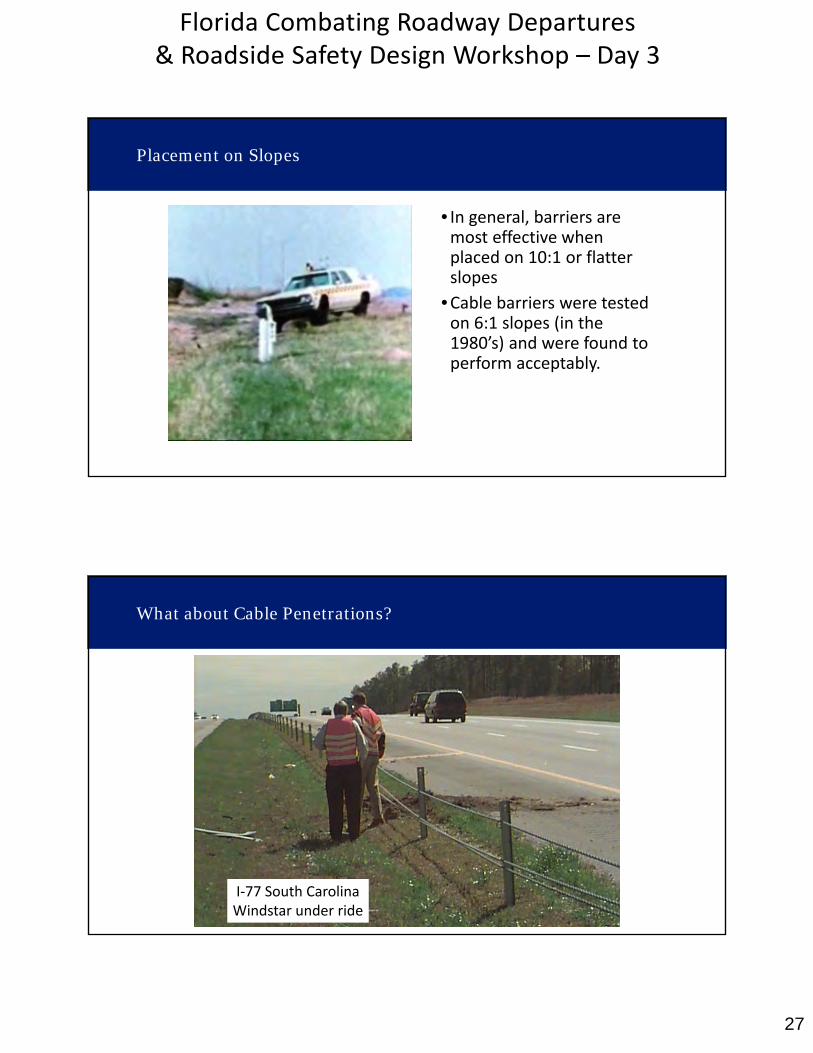
Placement on Slopes
• In general, barriers aremost effective whenplaced on 10:1 or flatterslopes
•Cable barriers were testedon 6:1 slopes (in the1980’s) and were found toperform acceptably.
I‐77 South CarolinaWindstar under ride
What about Cable Penetrations?
28
Florida Combating Roadway Departures & Roadside Safety Design Workshop – Day 3
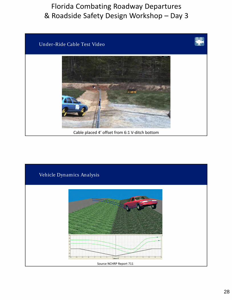
Cable placed 4’ offset from 6:1 V‐ditch bottom
Under-Ride Cable Test Video
Source NCHRP Report 711
Vehicle Dynamics Analysis
29
Florida Combating Roadway Departures & Roadside Safety Design Workshop – Day 3
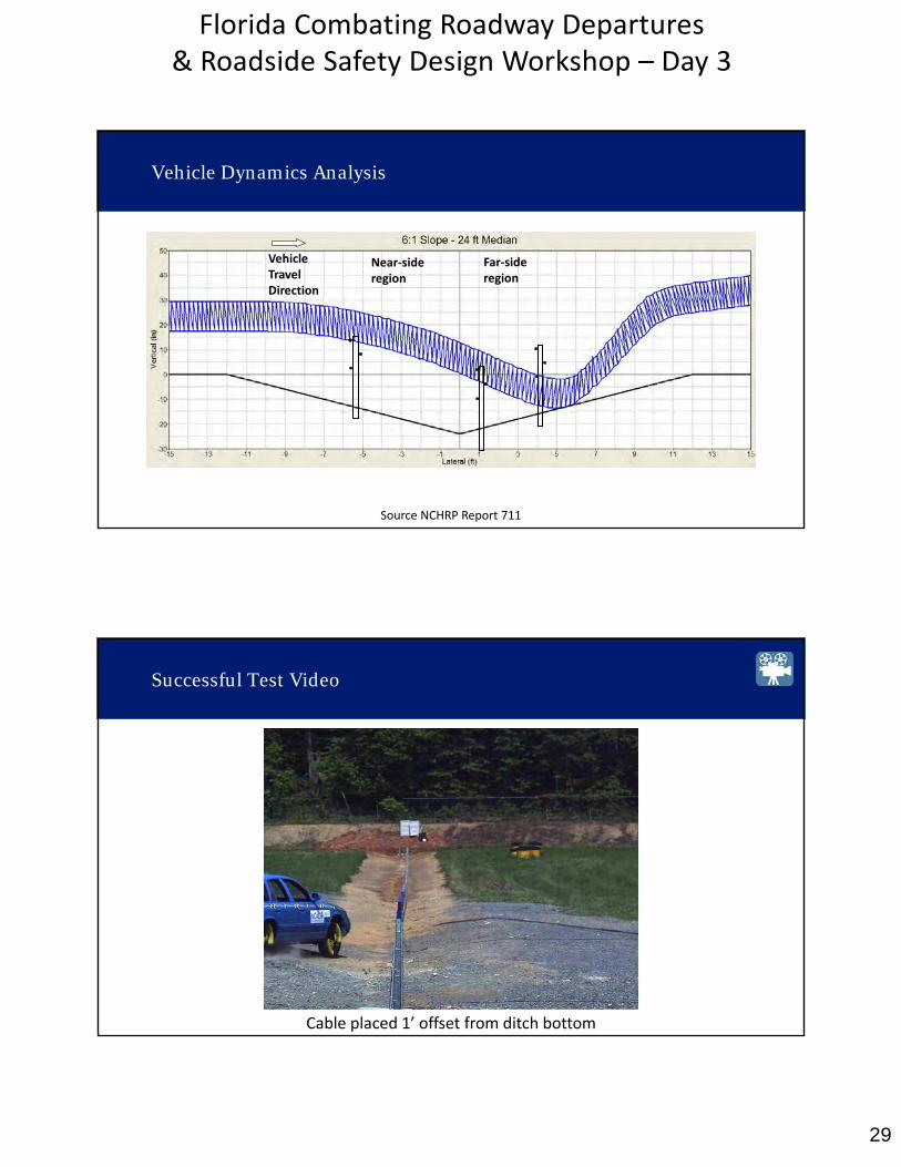
Vehicle Dynamics Analysis
Vehicle Travel Direction
Near‐side region
Far‐side region
Source NCHRP Report 711
Successful Test Video
Cable placed 1’ offset from ditch bottom
30
Florida Combating Roadway Departures & Roadside Safety Design Workshop – Day 3
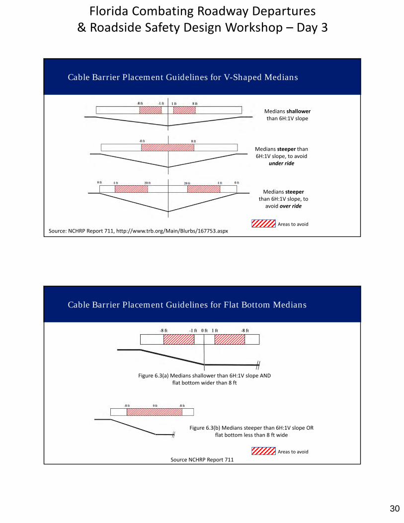
Cable Barrier Placement Guidelines for V-Shaped Medians
Source: NCHRP Report 711, http://www.trb.org/Main/Blurbs/167753.aspx
Medians shallowerthan 6H:1V slope
Medians steeper than 6H:1V slope, to avoid
under ride
Medians steeperthan 6H:1V slope, to
avoid over ride
Areas to avoid
Cable Barrier Placement Guidelines for Flat Bottom Medians
Source NCHRP Report 711
Figure 6.3(b) Medians steeper than 6H:1V slope OR flat bottom less than 8 ft wide
Figure 6.3(a) Medians shallower than 6H:1V slope AND flat bottom wider than 8 ft
Areas to avoid
31
Florida Combating Roadway Departures & Roadside Safety Design Workshop – Day 3
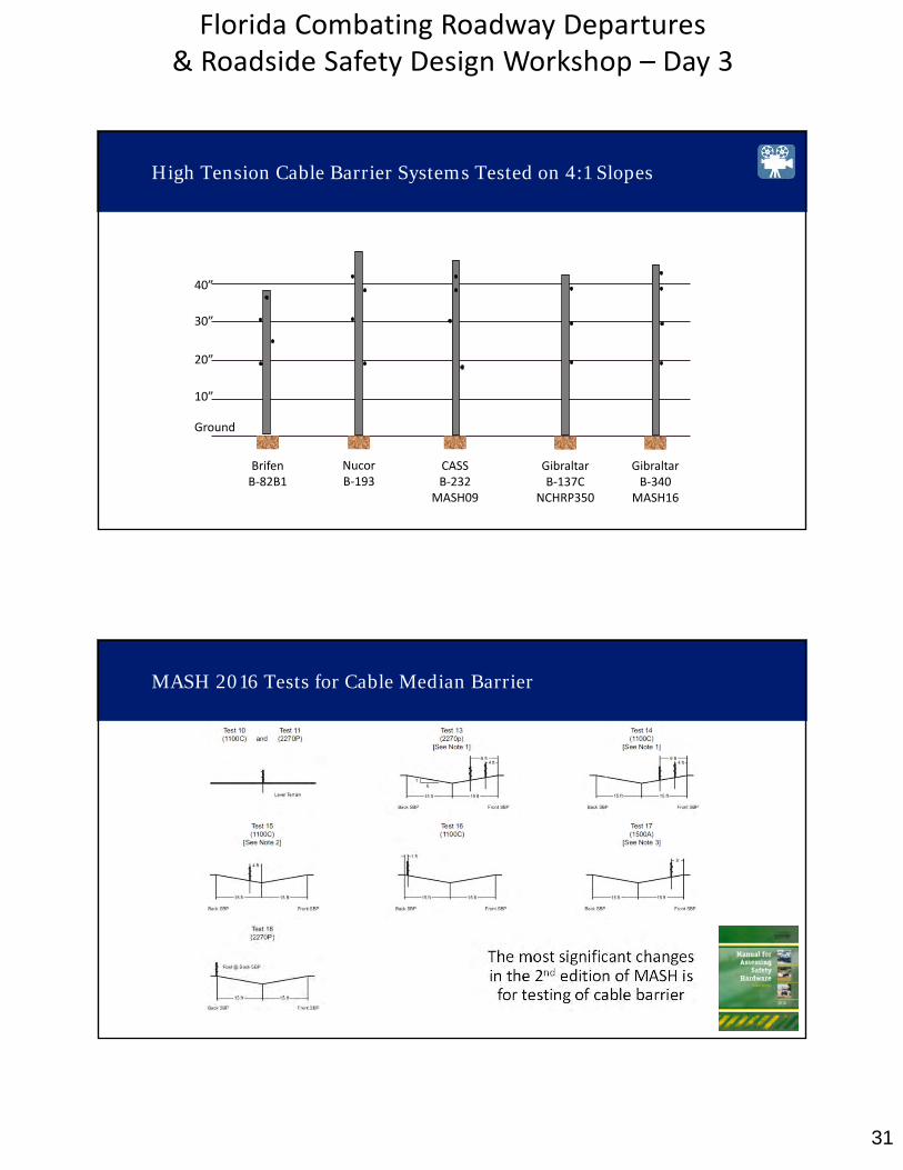
High Tension Cable Barrier Systems Tested on 4:1 Slopes
40”
30”
20”
10”
Ground
BrifenB‐82B1
NucorB‐193
CASSB‐232
MASH09
GibraltarB‐137C
NCHRP350
GibraltarB‐340
MASH16
MASH 2016 Tests for Cable Median Barrier
The most significant changes in the 2nd edition of MASH is for testing of cable barrier
32
Florida Combating Roadway Departures & Roadside Safety Design Workshop – Day 3
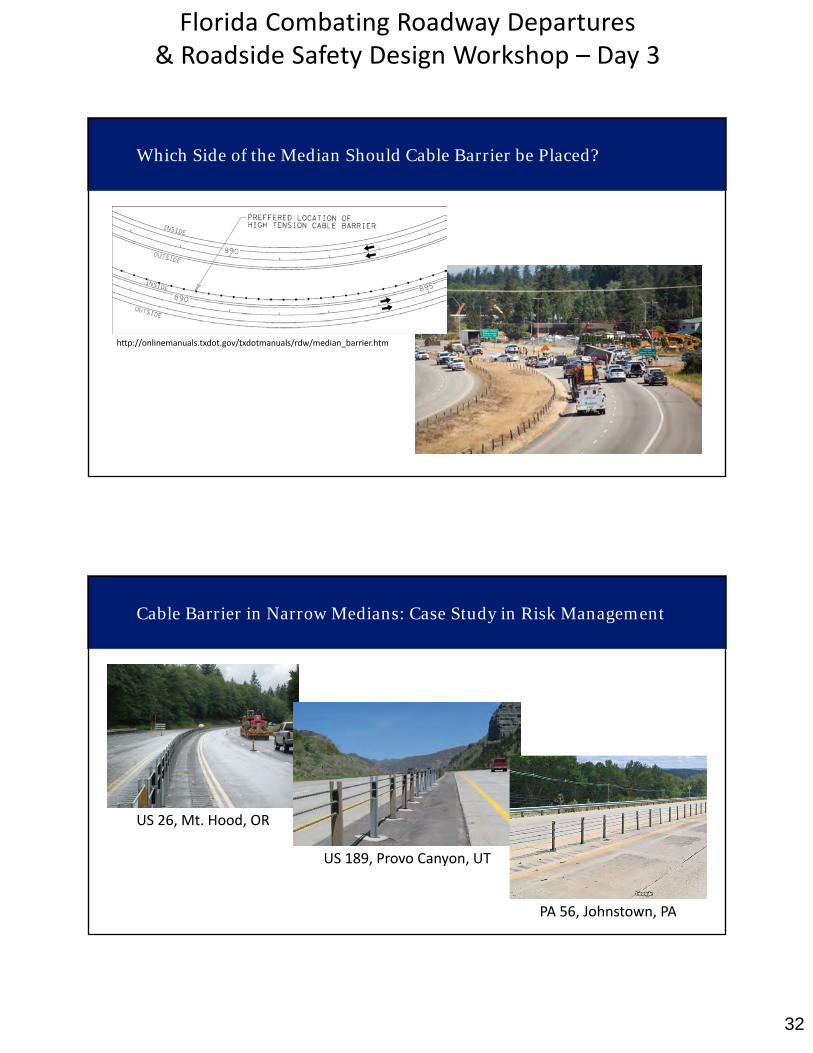
Which Side of the Median Should Cable Barrier be Placed?
http://onlinemanuals.txdot.gov/txdotmanuals/rdw/median_barrier.htm
US 26, Mt. Hood, OR
US 189, Provo Canyon, UT
Cable Barrier in Narrow Medians: Case Study in Risk Management
PA 56, Johnstown, PA
33
Florida Combating Roadway Departures & Roadside Safety Design Workshop – Day 3
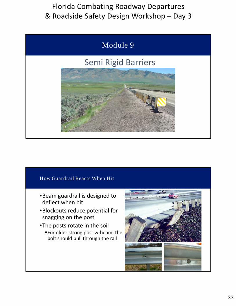
Semi Rigid Barriers
Module 9
How Guardrail Reacts When Hit
•Beam guardrail is designed todeflect when hit
•Blockouts reduce potential forsnagging on the post
•The posts rotate in the soilFor older strong post w‐beam, thebolt should pull through the rail
34
Florida Combating Roadway Departures & Roadside Safety Design Workshop – Day 3
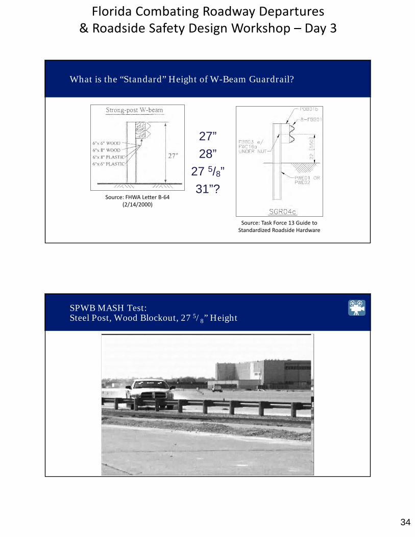
27”
28”
27 5/8”
31”?Source: FHWA Letter B‐64
(2/14/2000)
Source: Task Force 13 Guide to Standardized Roadside Hardware
What is the “Standard” Height of W-Beam Guardrail?
SPWB MASH Test: Steel Post, Wood Blockout, 27 5/8” Height
35
Florida Combating Roadway Departures & Roadside Safety Design Workshop – Day 3
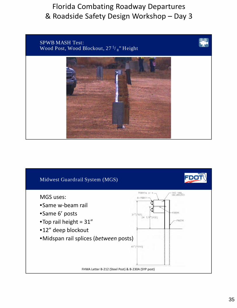
SPWB MASH Test: Wood Post, Wood Blockout, 27 5/8” Height
FHWA Letter B‐212 (Steel Post) & B‐230A (SYP post)
Midwest Guardrail System (MGS)
MGS uses:
•Same w‐beam rail
•Same 6’ posts
•Top rail height = 31”•12” deep blockout•Midspan rail splices (between posts)

36
Florida Combating Roadway Departures & Roadside Safety Design Workshop – Day 3
Working Width – 48.6”FHWA Letter B‐212
MGS Test: Steel Post, 12” Wood Blockout, 31” Height
Working Width – 53.8”FHWA Letter B‐230A
MGS Test: Wood Post, 12” Wood Blockout, 31” Height
37
Florida Combating Roadway Departures & Roadside Safety Design Workshop – Day 3
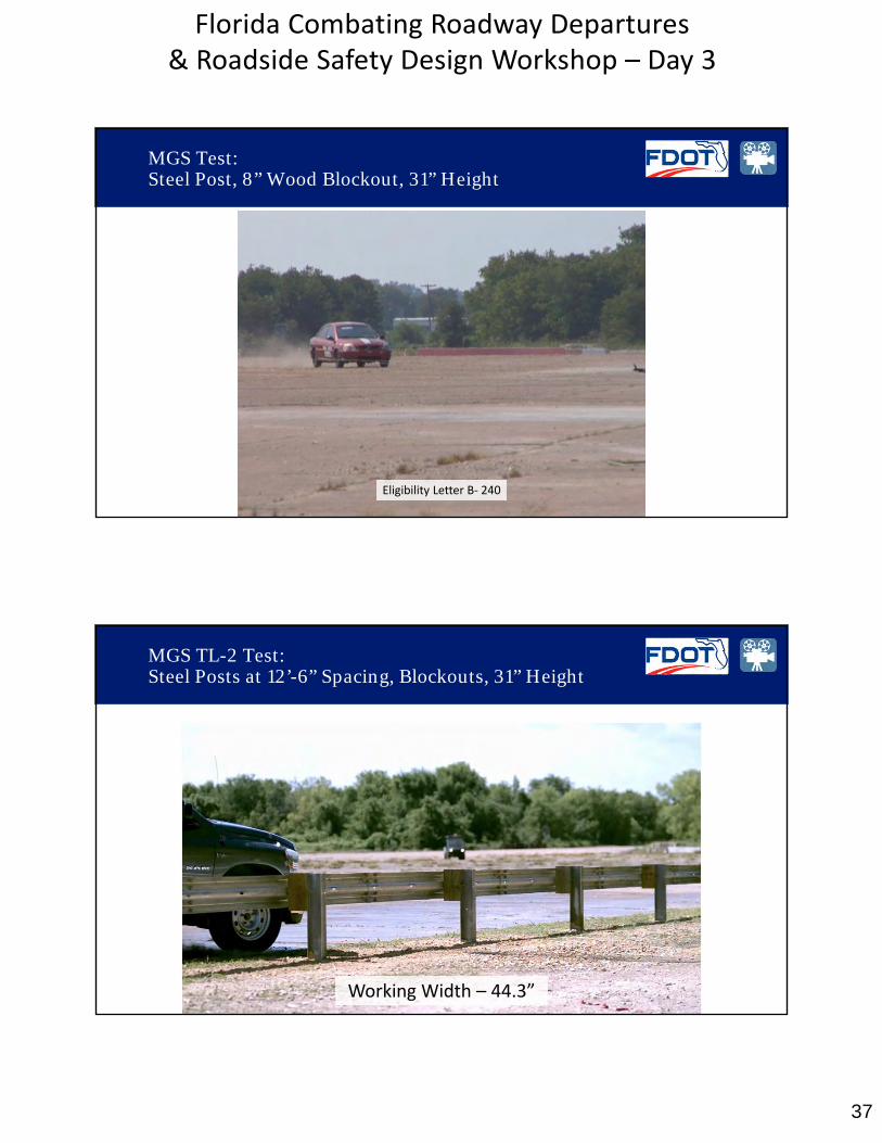
Eligibility Letter B‐ 240
MGS Test: Steel Post, 8” Wood Blockout, 31” Height
Working Width – 44.3”
MGS TL-2 Test: Steel Posts at 12’-6” Spacing, Blockouts, 31” Height
38
Florida Combating Roadway Departures & Roadside Safety Design Workshop – Day 3
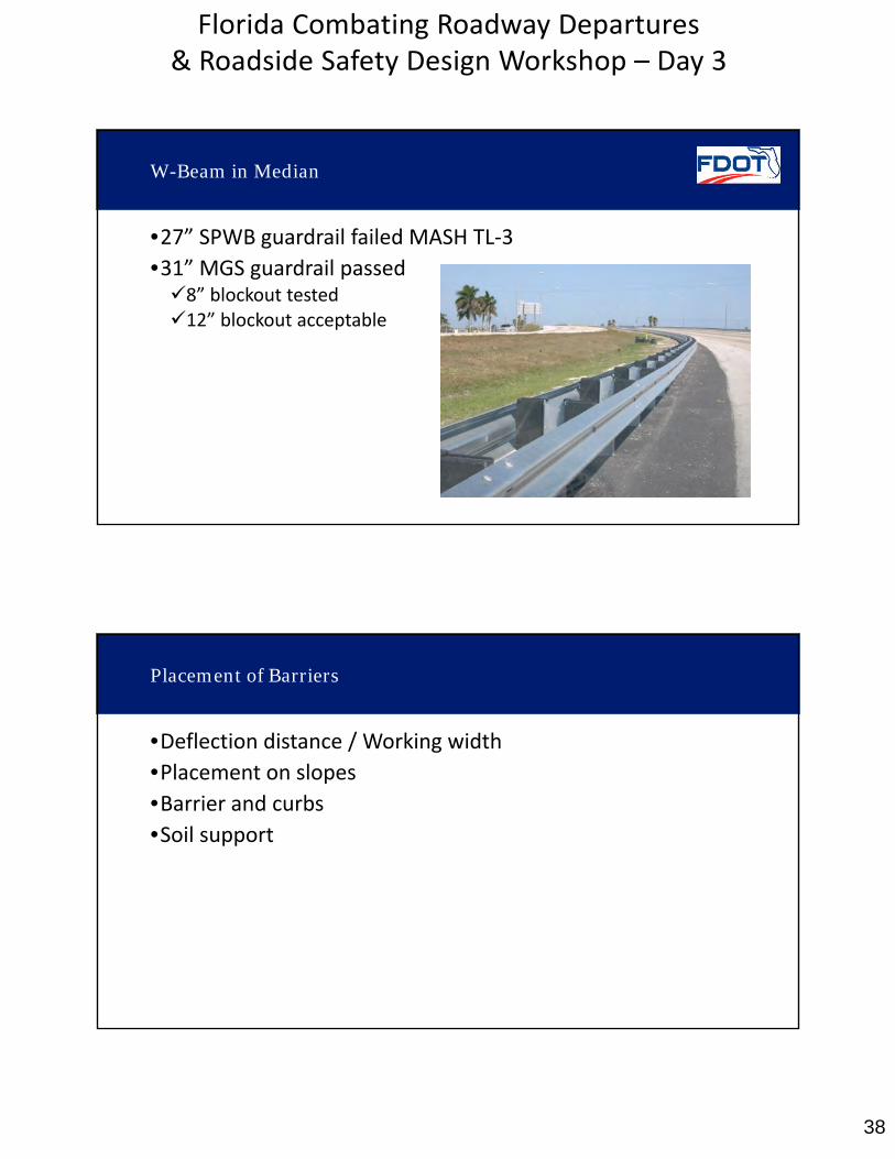
W-Beam in Median
•27” SPWB guardrail failed MASH TL‐3
•31” MGS guardrail passed8” blockout tested12” blockout acceptable
Placement of Barriers
•Deflection distance / Working width
•Placement on slopes
•Barrier and curbs•Soil support
39
Florida Combating Roadway Departures & Roadside Safety Design Workshop – Day 3
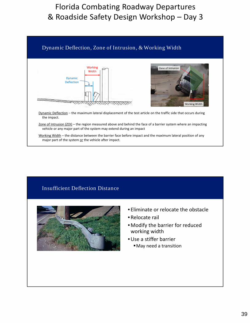
Dynamic Deflection – the maximum lateral displacement of the test article on the traffic side that occurs during the impact.
Zone of Intrusion (ZOI) – the region measured above and behind the face of a barrier system where an impacting vehicle or any major part of the system may extend during an impact
Working Width – the distance between the barrier face before impact and the maximum lateral position of any major part of the system or the vehicle after impact.
DynamicDeflection
Working Width
Dynamic Deflection, Zone of Intrusion, & Working Width
Insufficient Deflection Distance
•Eliminate or relocate the obstacle
•Relocate rail•Modify the barrier for reducedworking width
•Use a stiffer barrierMay need a transition
40
Florida Combating Roadway Departures & Roadside Safety Design Workshop – Day 3
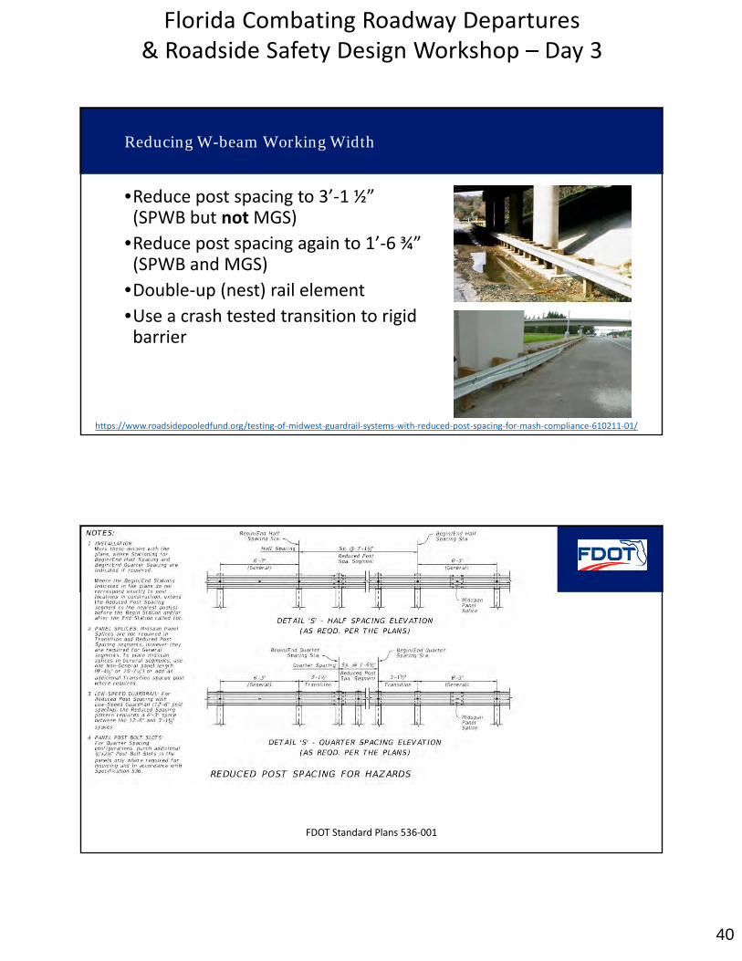
Reducing W-beam Working Width
•Reduce post spacing to 3’‐1 ½”(SPWB but notMGS)
•Reduce post spacing again to 1’‐6 ¾”(SPWB and MGS)
•Double‐up (nest) rail element
•Use a crash tested transition to rigidbarrier
https://www.roadsidepooledfund.org/testing‐of‐midwest‐guardrail‐systems‐with‐reduced‐post‐spacing‐for‐mash‐compliance‐610211‐01/
FDOT Standard Plans 536‐001
41
Florida Combating Roadway Departures & Roadside Safety Design Workshop – Day 3
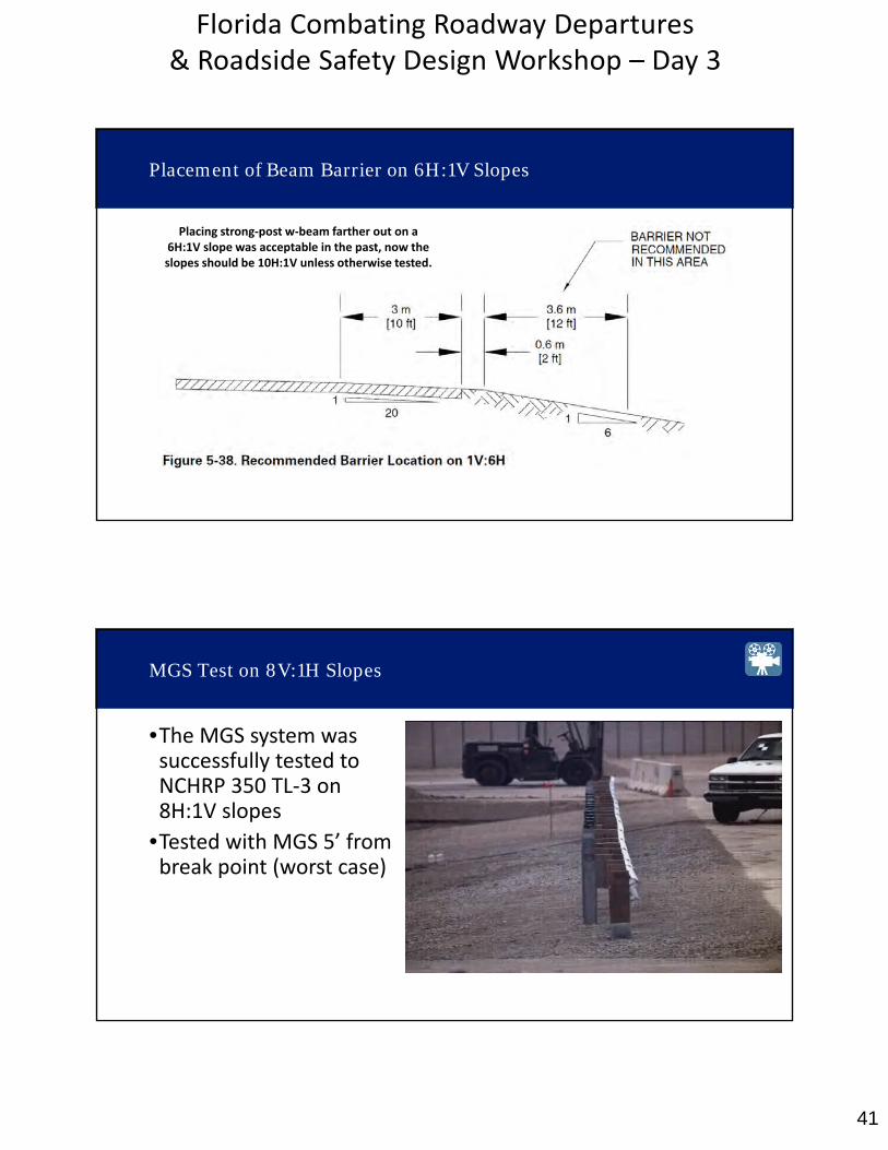
Placement of Beam Barrier on 6H:1V Slopes
Placing strong‐post w‐beam farther out on a 6H:1V slope was acceptable in the past, now the slopes should be 10H:1V unless otherwise tested.
MGS Test on 8V:1H Slopes
•The MGS system wassuccessfully tested toNCHRP 350 TL‐3 on8H:1V slopes
•Tested with MGS 5’ frombreak point (worst case)
42
Florida Combating Roadway Departures & Roadside Safety Design Workshop – Day 3
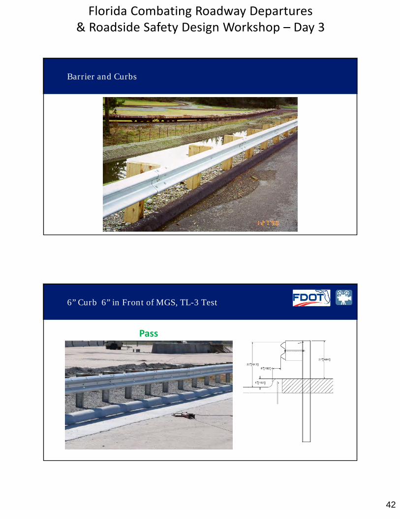
Barrier and Curbs
6” Curb 6” in Front of MGS, TL-3 Test
Pass
43
Florida Combating Roadway Departures & Roadside Safety Design Workshop – Day 3
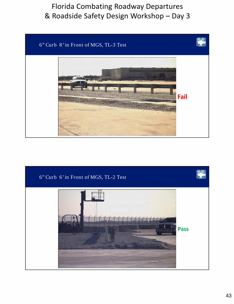
6” Curb 8’ in Front of MGS, TL-3 Test
Fail
6” Curb 6’ in Front of MGS, TL-2 Test
Pass

44
Florida Combating Roadway Departures & Roadside Safety Design Workshop – Day 3
Alternative Curb Options
Soil Support
45
Florida Combating Roadway Departures & Roadside Safety Design Workshop – Day 3
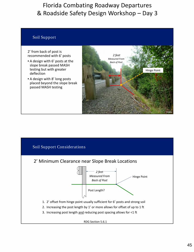
2’ from back of post is recommended with 6’ posts
• A design with 6’ posts at theslope break passed MASHtesting but with greaterdeflection
• A design with 8’ long postsplaced beyond the slope breakpassed MASH testing
Soil Support
2 feetMeasured From
Back of Post
Hinge Point
FHWA
Soil Support Considerations
2’ Minimum Clearance near Slope Break Locations
1. 2’ offset from hinge point usually sufficient for 6’ posts and strong soil
2. Increasing the post length by 1’ or more allows for offset of up to 1 ft
3. Increasing post length and reducing post spacing allows for <1 ft
2 feet
Measured From
Back of PostHinge Point
Post Length?
RDG Section 5.6.1
46
Florida Combating Roadway Departures & Roadside Safety Design Workshop – Day 3
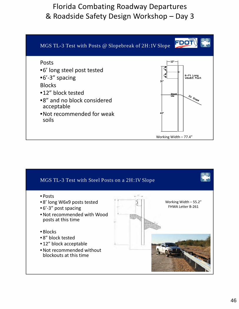
MGS TL-3 Test with Posts @ Slopebreak of 2H:1V Slope
Posts•6’ long steel post tested•6’‐3” spacingBlocks•12” block tested•8” and no block consideredacceptable
•Not recommended for weaksoils
Working Width – 77.4”
MGS TL-3 Test with Steel Posts on a 2H:1V Slope
•Posts•8’ long W6x9 posts tested•6’‐3” post spacing•Not recommended with Woodposts at this time
•Blocks•8” block tested•12” block acceptable•Not recommended withoutblockouts at this time
Working Width – 55.2”FHWA Letter B‐261
47
Florida Combating Roadway Departures & Roadside Safety Design Workshop – Day 3
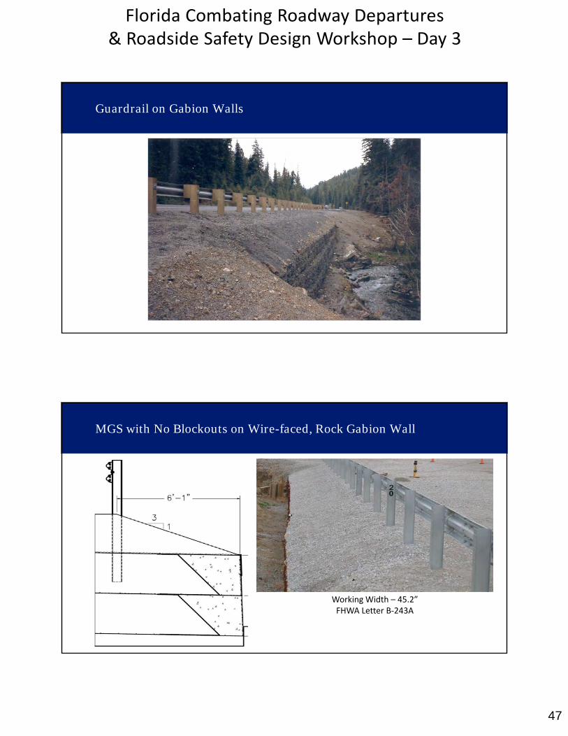
Guardrail on Gabion Walls
MGS with No Blockouts on Wire-faced, Rock Gabion Wall
Working Width – 45.2”FHWA Letter B‐243A

48
Florida Combating Roadway Departures & Roadside Safety Design Workshop – Day 3
Intercepted Length of Need
FHWA Letter B‐209 – NCHRP 350 TL 2
FDOT Standard Plans 536‐001CRT Systems for Side Roads & Driveways
MASH TL-3 Test of Short Radius Guardrail
49
Florida Combating Roadway Departures & Roadside Safety Design Workshop – Day 3
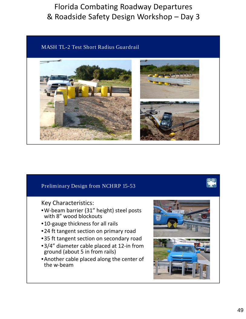
MASH TL-2 Test Short Radius Guardrail
Preliminary Design from NCHRP 15-53
Key Characteristics:•W‐beam barrier (31” height) steel postswith 8” wood blockouts
•10‐gauge thickness for all rails•24 ft tangent section on primary road•35 ft tangent section on secondary road•3/4” diameter cable placed at 12‐in fromground (about 5 in from rails)
•Another cable placed along the center ofthe w‐beam
50
Florida Combating Roadway Departures & Roadside Safety Design Workshop – Day 3
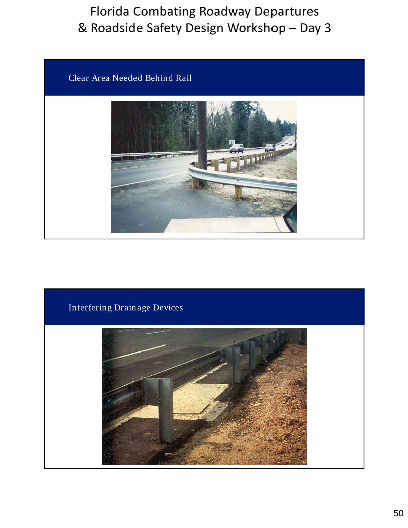
Clear Area Needed Behind Rail
Interfering Drainage Devices
51
Florida Combating Roadway Departures & Roadside Safety Design Workshop – Day 3
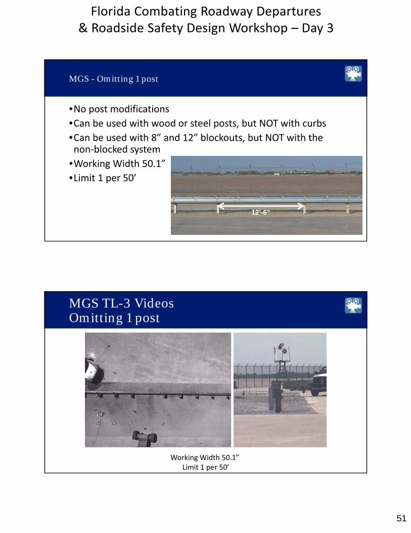
MGS - Omitting 1 post
•No post modifications
•Can be used with wood or steel posts, but NOT with curbs•Can be used with 8” and 12” blockouts, but NOT with thenon‐blocked system
•Working Width 50.1”
•Limit 1 per 50’
12’-6”
MGS TL-3 VideosOmitting 1 post
Working Width 50.1” Limit 1 per 50’

52
Florida Combating Roadway Departures & Roadside Safety Design Workshop – Day 3
For 27 ¾” Guardrail•3 weakened posts on each side ofspan with double 8” blockouts
•100 feet of nested rail
For 31” (MGS) Guardrail•3 weakened posts on each side ofspan with single 12” blockouts
•Single rail
FHWA Letter B‐ 58 (350) & B‐189 (MASH)
Long Span Designs
MGS TL-3 Test Omitting 3 Posts
Working Width – 94” Eligibility Letter B‐189
53
Florida Combating Roadway Departures & Roadside Safety Design Workshop – Day 3
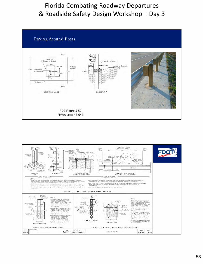
RDG Figure 5‐52FHWA Letter B‐64B
Paving Around Posts
FDOT Standard Plan 536‐001
54
Florida Combating Roadway Departures & Roadside Safety Design Workshop – Day 3
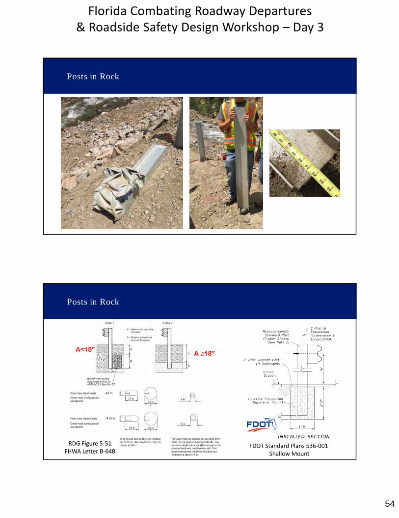
Posts in Rock
A<18” A ≥18”
RDG Figure 5‐51FHWA Letter B‐64B
Posts in Rock
FDOT Standard Plans 536‐001Shallow Mount
55
Florida Combating Roadway Departures & Roadside Safety Design Workshop – Day 3
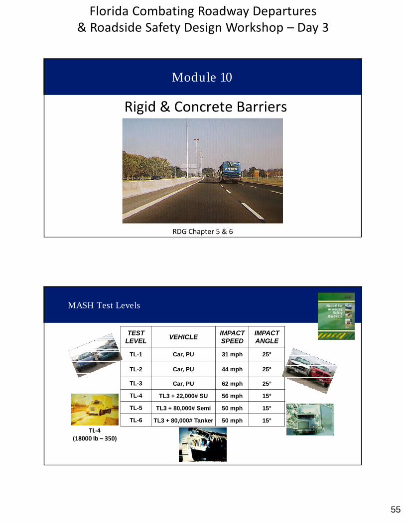
Rigid & Concrete Barriers
RDG Chapter 5 & 6
Module 10
MASH Test Levels
TESTLEVEL
VEHICLEIMPACTSPEED
IMPACT ANGLE
TL-1 Car, PU 31 mph 25°
TL-2 Car, PU 44 mph 25°
TL-3 Car, PU 62 mph 25°
TL-4 TL3 + 22,000# SU 56 mph 15°
TL-5 TL3 + 80,000# Semi 50 mph 15°
TL-6 TL3 + 80,000# Tanker 50 mph 15°
TL‐4(18000 lb – 350)
56
Florida Combating Roadway Departures & Roadside Safety Design Workshop – Day 3
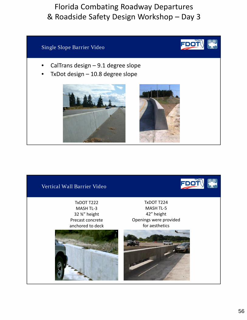
Single Slope Barrier Video
• CalTrans design – 9.1 degree slope
• TxDot design – 10.8 degree slope
TxDOT T224MASH TL‐542” height
Openings were provided for aesthetics
TxDOT T222MASH TL‐332 ¾” height
Precast concrete anchored to deck
Vertical Wall Barrier Video
57
Florida Combating Roadway Departures & Roadside Safety Design Workshop – Day 3
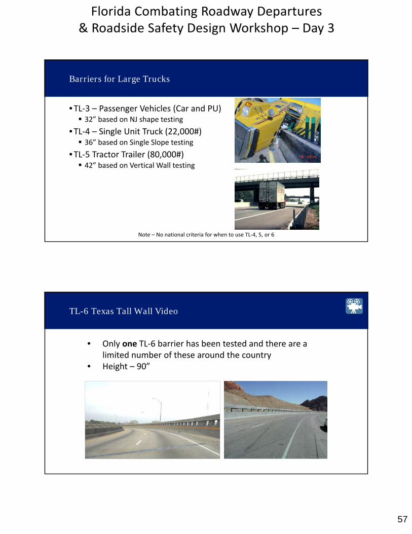
Barriers for Large Trucks
•TL‐3 – Passenger Vehicles (Car and PU) 32” based on NJ shape testing
•TL‐4 – Single Unit Truck (22,000#) 36” based on Single Slope testing
•TL‐5 Tractor Trailer (80,000#) 42” based on Vertical Wall testing
Note – No national criteria for when to use TL‐4, 5, or 6
• Only one TL‐6 barrier has been tested and there are alimited number of these around the country
• Height – 90”
TL-6 Texas Tall Wall Video
58
Florida Combating Roadway Departures & Roadside Safety Design Workshop – Day 3
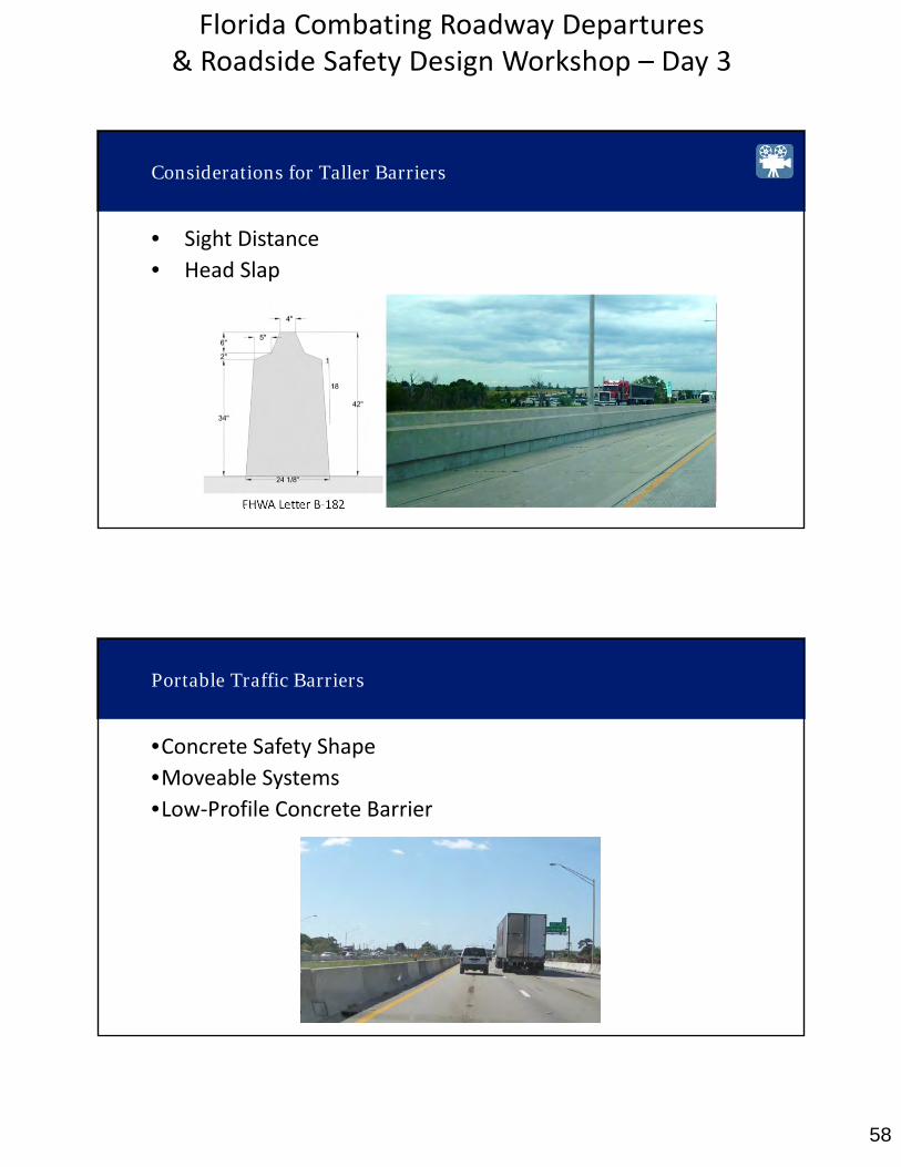
FHWA Letter B‐182
Considerations for Taller Barriers
• Sight Distance
• Head Slap
Portable Traffic Barriers
•Concrete Safety Shape•Moveable Systems
•Low‐Profile Concrete Barrier

59
Florida Combating Roadway Departures & Roadside Safety Design Workshop – Day 3
Portable Concrete Barriers Details
•Shape•Connections•Deflection•Anchorage
RDG Chapter 9
FHWA Letter B‐215
Iowa F-Shape Precast Barrier Video

60
Florida Combating Roadway Departures & Roadside Safety Design Workshop – Day 3
Deflection Factors
•Number of joints
•Connection type•Anchorage
61
Florida Combating Roadway Departures & Roadside Safety Design Workshop – Day 3
62
Florida Combating Roadway Departures & Roadside Safety Design Workshop – Day 3
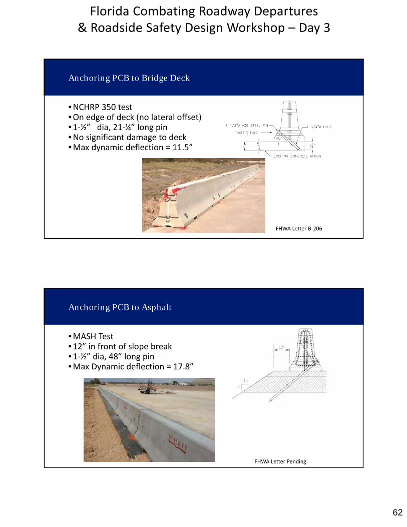
Anchoring PCB to Bridge Deck
•NCHRP 350 test•On edge of deck (no lateral offset)•1‐½” dia, 21‐¼” long pin•No significant damage to deck•Max dynamic deflection = 11.5”
FHWA Letter B‐206
Anchoring PCB to Asphalt
•MASH Test•12” in front of slope break•1‐½” dia, 48” long pin•Max Dynamic deflection = 17.8”
FHWA Letter Pending
63
Florida Combating Roadway Departures & Roadside Safety Design Workshop – Day 3
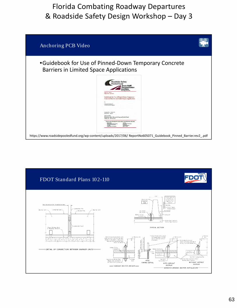
Anchoring PCB Video
•Guidebook for Use of Pinned‐Down Temporary ConcreteBarriers in Limited Space Applications
https://www.roadsidepooledfund.org/wp‐content/uploads/2017/06/ ReportNo605071_Guidebook_Pinned_Barrier.rev2_.pdf
FDOT Standard Plans 102-110
64
Florida Combating Roadway Departures & Roadside Safety Design Workshop – Day 3
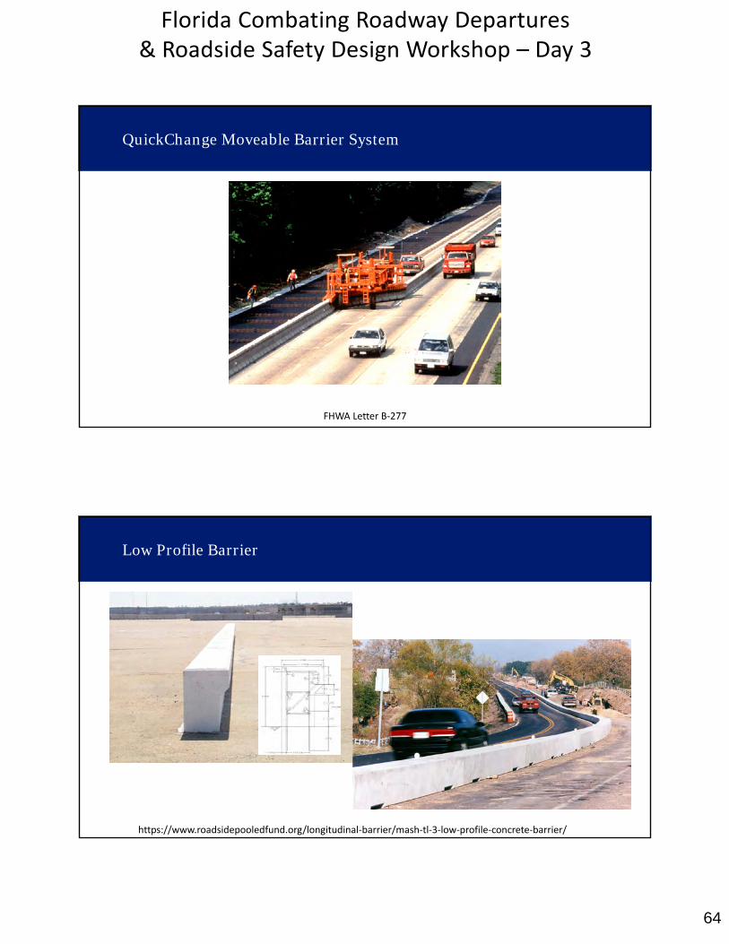
QuickChange Moveable Barrier System
FHWA Letter B‐277
Low Profile Barrier
https://www.roadsidepooledfund.org/longitudinal‐barrier/mash‐tl‐3‐low‐profile‐concrete‐barrier/
65
Florida Combating Roadway Departures & Roadside Safety Design Workshop – Day 3
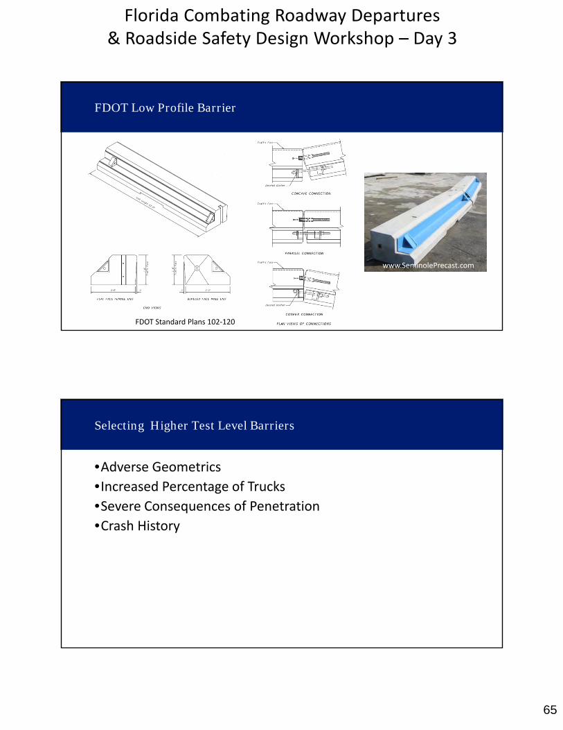
FDOT Low Profile Barrier
FDOT Standard Plans 102‐120
www.SeminolePrecast.com
Selecting Higher Test Level Barriers
•Adverse Geometrics
•Increased Percentage of Trucks•Severe Consequences of Penetration•Crash History
66
Florida Combating Roadway Departures & Roadside Safety Design Workshop – Day 3
Questions/Comments
Day 3 To-Dos
• MASH Crash Testing Overview Video(15 minutes)https://connectdot.connectsolutions.com/rsd_mash/
• Visit https://www.roadsidepooledfund.org/mash‐implementation/search/