Embed Size (px)
Citation preview
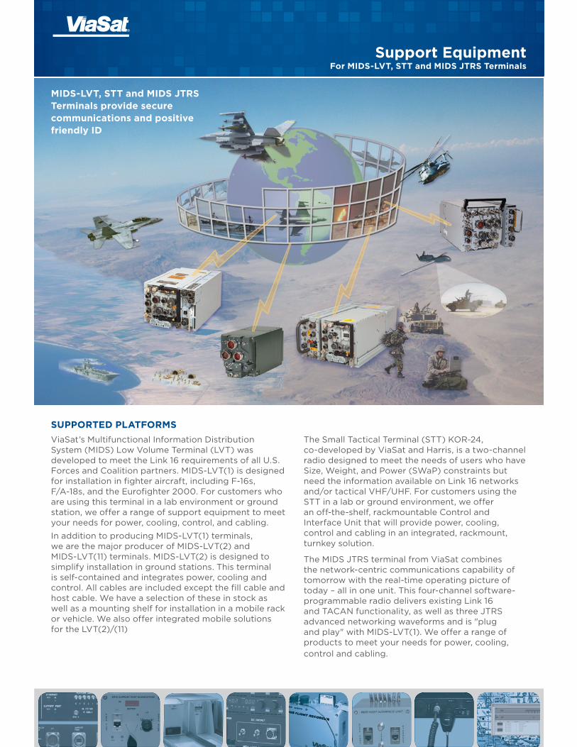
Support EquipmentFor MIDS-LVT, STT and MIDS JTRS Terminals
MIDS-LVT, STT and MIDS JTRS Terminals provide secure communications and positive friendly ID
SUPPORTED PLATFORMSViaSat’s Multifunctional Information Distribution System (MIDS) Low Volume Terminal (LVT) was developed to meet the Link 16 requirements of all U.S. Forces and Coalition partners. MIDS-LVT(1) is designed for installation in fighter aircraft, including F-16s, F/A-18s, and the Eurofighter 2000. For customers who are using this terminal in a lab environment or ground station, we offer a range of support equipment to meet your needs for power, cooling, control, and cabling.
In addition to producing MIDS-LVT(1) terminals, we are the major producer of MIDS-LVT(2) and MIDS-LVT(11) terminals. MIDS-LVT(2) is designed to simplify installation in ground stations. This terminal is self-contained and integrates power, cooling and control. All cables are included except the fill cable and host cable. We have a selection of these in stock as well as a mounting shelf for installation in a mobile rack or vehicle. We also offer integrated mobile solutions for the LVT(2)/(11)
The Small Tactical Terminal (STT) KOR-24, co-developed by ViaSat and Harris, is a two-channel radio designed to meet the needs of users who have Size, Weight, and Power (SWaP) constraints but need the information available on Link 16 networks and/or tactical VHF/UHF. For customers using the STT in a lab or ground environment, we offer an off-the-shelf, rackmountable Control and Interface Unit that will provide power, cooling, control and cabling in an integrated, rackmount, turnkey solution.
The MIDS JTRS terminal from ViaSat combines the network-centric communications capability of tomorrow with the real-time operating picture of today – all in one unit. This four-channel software-programmable radio delivers existing Link 16 and TACAN functionality, as well as three JTRS advanced networking waveforms and is "plug and play" with MIDS-LVT(1). We offer a range of products to meet your needs for power, cooling, control and cabling.
Support Equipment for MIDS-LVT, STT, and MIDS JTRS Terminals
2
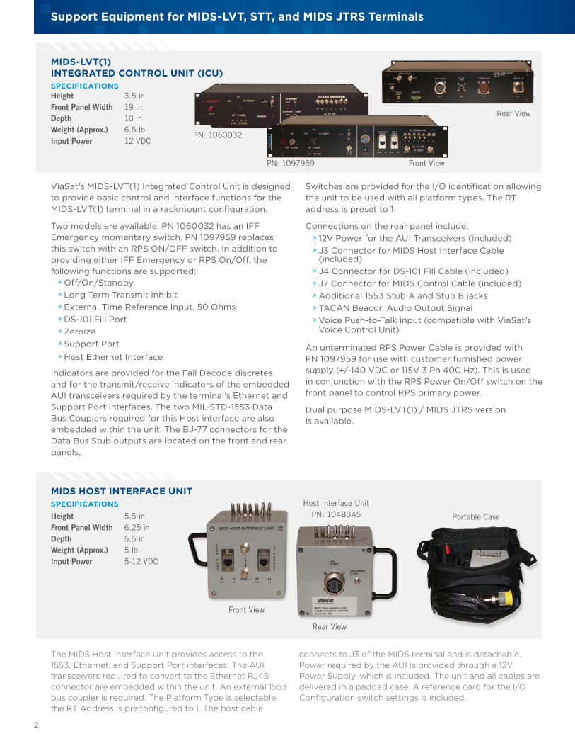
MIDS-LVT(1)INTEGRATED CONTROL UNIT (ICU)SPECIFICATIONSHeight 3.5 in Front Panel Width 19 inDepth 10 in Weight (Approx.) 6.5 lbInput Power 12 VDC
ViaSat’s MIDS-LVT(1) Integrated Control Unit is designed to provide basic control and interface functions for the MIDS-LVT(1) terminal in a rackmount configuration.
Two models are available. PN 1060032 has an IFF Emergency momentary switch. PN 1097959 replaces this switch with an RPS ON/OFF switch. In addition to providing either IFF Emergency or RPS On/Off, the following functions are supported:
» Off/On/Standby » Long Term Transmit Inhibit » External Time Reference Input, 50 Ohms » DS-101 Fill Port » Zeroize » Support Port » Host Ethernet Interface
Indicators are provided for the Fail Decode discretes and for the transmit/receive indicators of the embedded AUI transceivers required by the terminal’s Ethernet and Support Port interfaces. The two MIL-STD-1553 Data Bus Couplers required for this Host interface are also embedded within the unit. The BJ-77 connectors for the Data Bus Stub outputs are located on the front and rear panels.
Rear View
Switches are provided for the I/O identification allowing the unit to be used with all platform types. The RT address is preset to 1.
Connections on the rear panel include: » 12V Power for the AUI Transceivers (included) » J3 Connector for MIDS Host Interface Cable (included) » J4 Connector for DS-101 Fill Cable (included) » J7 Connector for MIDS Control Cable (included) » Additional 1553 Stub A and Stub B jacks » TACAN Beacon Audio Output Signal » Voice Push-to-Talk input (compatible with ViaSat’s Voice Control Unit)
An unterminated RPS Power Cable is provided with PN 1097959 for use with customer furnished power supply (+/-140 VDC or 115V 3 Ph 400 Hz). This is used in conjunction with the RPS Power On/Off switch on the front panel to control RPS primary power.
Dual purpose MIDS-LVT(1) / MIDS JTRS version is available.
PN: 1060032
PN: 1097959 Front View
MIDS HOST INTERFACE UNITSPECIFICATIONSHeight 5.5 in Front Panel Width 6.25 in Depth 5.5 in Weight (Approx.) 5 lbInput Power 5-12 VDC
Rear View
Front View
The MIDS Host Interface Unit provides access to the 1553, Ethernet, and Support Port interfaces. The AUI transceivers required to convert to the Ethernet RJ45 connector are embedded within the unit. An external 1553 bus coupler is required. The Platform Type is selectable; the RT Address is preconfigured to 1. The host cable
Host Interface UnitPN: 1048345 Portable Case
connects to J3 of the MIDS terminal and is detachable. Power required by the AUI is provided through a 12V Power Supply, which is included. The unit and all cables are delivered in a padded case. A reference card for the I/O Configuration switch settings is included.
The following MIDS control functions are supported by the MIDS-LVT(1) Control Panel:
» On/Off
» Standby On/Off
» Long Term Transmit Inhibit (LTTI)
» Zeroize on Open
» Zeroize on Close
» I/O Identification
» RT Address
» Push to Talk 1 (PTT-1)
» Push to Talk 2 (PTT-2)
» MIL-STD 1553B Channels A and B (Host)
» MIL-STD-1553B Channels A and B (Monitor)
» MIDS Support Port
» MIDS Ethernet Port
3
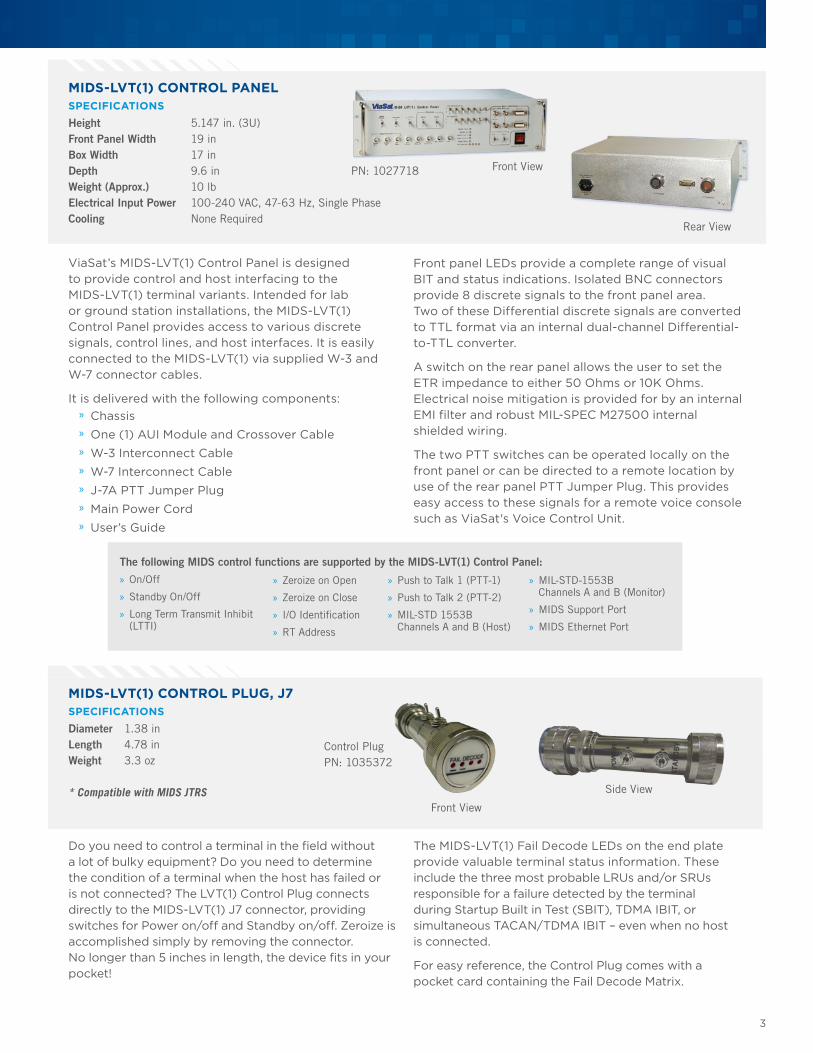
MIDS-LVT(1) CONTROL PANELSPECIFICATIONSHeight 5.147 in. (3U)Front Panel Width 19 inBox Width 17 inDepth 9.6 inWeight (Approx.) 10 lbElectrical Input Power 100-240 VAC, 47-63 Hz, Single PhaseCooling None Required
ViaSat’s MIDS-LVT(1) Control Panel is designed to provide control and host interfacing to the MIDS-LVT(1) terminal variants. Intended for lab or ground station installations, the MIDS-LVT(1) Control Panel provides access to various discrete signals, control lines, and host interfaces. It is easily connected to the MIDS-LVT(1) via supplied W-3 and W-7 connector cables.
It is delivered with the following components: » Chassis » One (1) AUI Module and Crossover Cable » W-3 Interconnect Cable » W-7 Interconnect Cable » J-7A PTT Jumper Plug » Main Power Cord » User’s Guide
Front View
Rear View
PN: 1027718
Front panel LEDs provide a complete range of visual BIT and status indications. Isolated BNC connectors provide 8 discrete signals to the front panel area. Two of these Differential discrete signals are converted to TTL format via an internal dual-channel Differential-to-TTL converter.
A switch on the rear panel allows the user to set the ETR impedance to either 50 Ohms or 10K Ohms. Electrical noise mitigation is provided for by an internal EMI filter and robust MIL-SPEC M27500 internal shielded wiring.
The two PTT switches can be operated locally on the front panel or can be directed to a remote location by use of the rear panel PTT Jumper Plug. This provides easy access to these signals for a remote voice console such as ViaSat's Voice Control Unit.
Control PlugPN: 1035372
MIDS-LVT(1) CONTROL PLUG, J7SPECIFICATIONSDiameter 1.38 inLength 4.78 inWeight 3.3 oz
* Compatible with MIDS JTRS
Do you need to control a terminal in the field without a lot of bulky equipment? Do you need to determine the condition of a terminal when the host has failed or is not connected? The LVT(1) Control Plug connects directly to the MIDS-LVT(1) J7 connector, providing switches for Power on/off and Standby on/off. Zeroize is accomplished simply by removing the connector. No longer than 5 inches in length, the device fits in your pocket!
The MIDS-LVT(1) Fail Decode LEDs on the end plate provide valuable terminal status information. These include the three most probable LRUs and/or SRUs responsible for a failure detected by the terminal during Startup Built in Test (SBIT), TDMA IBIT, or simultaneous TACAN/TDMA IBIT – even when no host is connected.
For easy reference, the Control Plug comes with a pocket card containing the Fail Decode Matrix.
Front View
Side View
Support Equipment for MIDS-LVT, STT, and MIDS JTRS Terminals
4
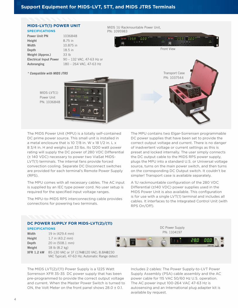
The MPU contains two Elgar-Sorrensen programmable DC power supplies that have been set to provide the correct output voltage and current. There is no danger of inadvertent voltage or current settings as this is preset and locked internally. The user simply connects the DC output cable to the MIDS RPS power supply, plugs the MPU into a standard U.S. or Universal voltage source, turns on the main power switch, and then turns on the corresponding DC Output switch. It couldn’t be simpler! Transport case is available separately.
A 1U rackmountable configuration of the 280 VDC Differential (±140 VDC) power supplies used in the MIDS Power Unit is also available. This configuration is for use with a single LVT(1) terminal and includes all cables. It interfaces to the Integrated Control Unit (with RPS On/Off).
DC POWER SUPPLY FOR MIDS-LVT(2)/(11)SPECIFICATIONSWidth 19 in (429.4 mm)Height 1.7 in (43.2 mm)Depth 20 in (508.1 mm)Weight 18 lb (8.2 kg)XFR 1.2 kW 85-130 VAC or 1F (17A@120 VAC; 8.8A@230 VAC Typical), 47-63 Hz; Automatic Range detect
The MIDS LVT(2)/(11) Power Supply is a 1225 Watt Sorrenson XFR 35-35 DC power supply that has been pre-programmed to provide the correct output voltage and current. When the Master Power Switch is turned to ON, the Volt Meter on the front panel shows 28.0 ± 0.1.
MIDS-LVT(1) POWER UNITSPECIFICATIONSPower Unit PN 1036848Height 8.75 inWidth 10.875 inDepth 18.5 inWeight (Approx.) 33 lbElectrical Input Power 90 – 132 VAC, 47-63 Hz orAutoranging 180 – 264 VAC, 47-63 Hz
* Compatible with MIDS JTRS
MIDS-LVT(1)Power UnitPN: 1036848
DC Power SupplyPN: 1104197
Transport CasePN: 1037544
The MIDS Power Unit (MPU) is a totally self-contained DC prime power source. This small unit is installed in a metal enclosure that is 10 7/8 in. W x 18 1/2 in. L x 8 3/4 in. H and weighs just 33 lbs. Its 1200 watt power rating will supply the DC power of 280 VDC Differential (± 140 VDC) necessary to power two ViaSat MIDS-LVT(1) terminals. The internal fans provide forced convection cooling. Separate DC Disconnect switches are provided for each terminal’s Remote Power Supply (RPS).
The MPU comes with all necessary cables. The AC input is supplied by an IEC type power cord. No user setup is required for the specified input voltage ranges.
The MPU-to-MIDS RPS interconnecting cable provides connections for powering two terminals.
Front View
MIDS 1U Rackmountable Power Unit, PN: 1095983
Includes 2 cables: The Power Supply-to-LVT Power Supply Assembly (PSA) cable assembly and the AC power cable for 115 VAC 50/60 Hz U.S. operation. The AC power input 100-264 VAC 47-63 Hz is autosensing and an International plug adapter kit is available by request.
PN 1037542 (Transport Case)
5
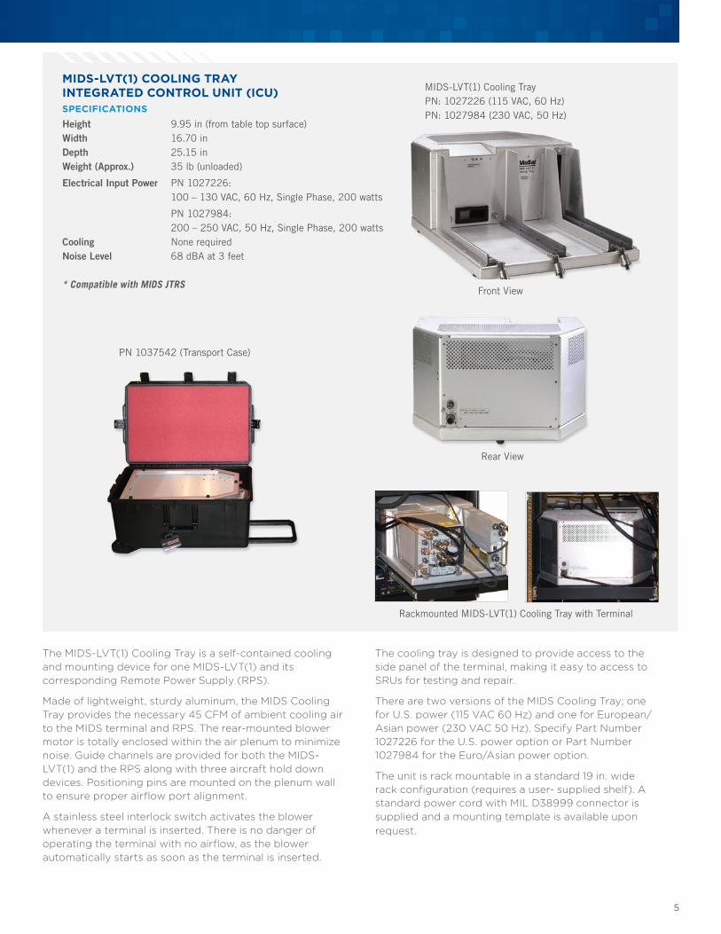
MIDS-LVT(1) COOLING TRAYINTEGRATED CONTROL UNIT (ICU) SPECIFICATIONSHeight 9.95 in (from table top surface)Width 16.70 inDepth 25.15 inWeight (Approx.) 35 lb (unloaded)
Electrical Input Power PN 1027226: 100 – 130 VAC, 60 Hz, Single Phase, 200 watts
PN 1027984: 200 – 250 VAC, 50 Hz, Single Phase, 200 wattsCooling None requiredNoise Level 68 dBA at 3 feet
* Compatible with MIDS JTRS
The MIDS-LVT(1) Cooling Tray is a self-contained cooling and mounting device for one MIDS-LVT(1) and its corresponding Remote Power Supply (RPS).
Made of lightweight, sturdy aluminum, the MIDS Cooling Tray provides the necessary 45 CFM of ambient cooling air to the MIDS terminal and RPS. The rear-mounted blower motor is totally enclosed within the air plenum to minimize noise. Guide channels are provided for both the MIDS-LVT(1) and the RPS along with three aircraft hold down devices. Positioning pins are mounted on the plenum wall to ensure proper airflow port alignment.
A stainless steel interlock switch activates the blower whenever a terminal is inserted. There is no danger of operating the terminal with no airflow, as the blower automatically starts as soon as the terminal is inserted.
The cooling tray is designed to provide access to the side panel of the terminal, making it easy to access to SRUs for testing and repair.
There are two versions of the MIDS Cooling Tray; one for U.S. power (115 VAC 60 Hz) and one for European/Asian power (230 VAC 50 Hz). Specify Part Number 1027226 for the U.S. power option or Part Number 1027984 for the Euro/Asian power option.
The unit is rack mountable in a standard 19 in. wide rack configuration (requires a user- supplied shelf). A standard power cord with MIL D38999 connector is supplied and a mounting template is available upon request.
Front View
Rear View
Rackmounted MIDS-LVT(1) Cooling Tray with Terminal
MIDS-LVT(1) Cooling Tray PN: 1027226 (115 VAC, 60 Hz)PN: 1027984 (230 VAC, 50 Hz)
Support Equipment for MIDS-LVT, STT, and MIDS JTRS Terminals
6
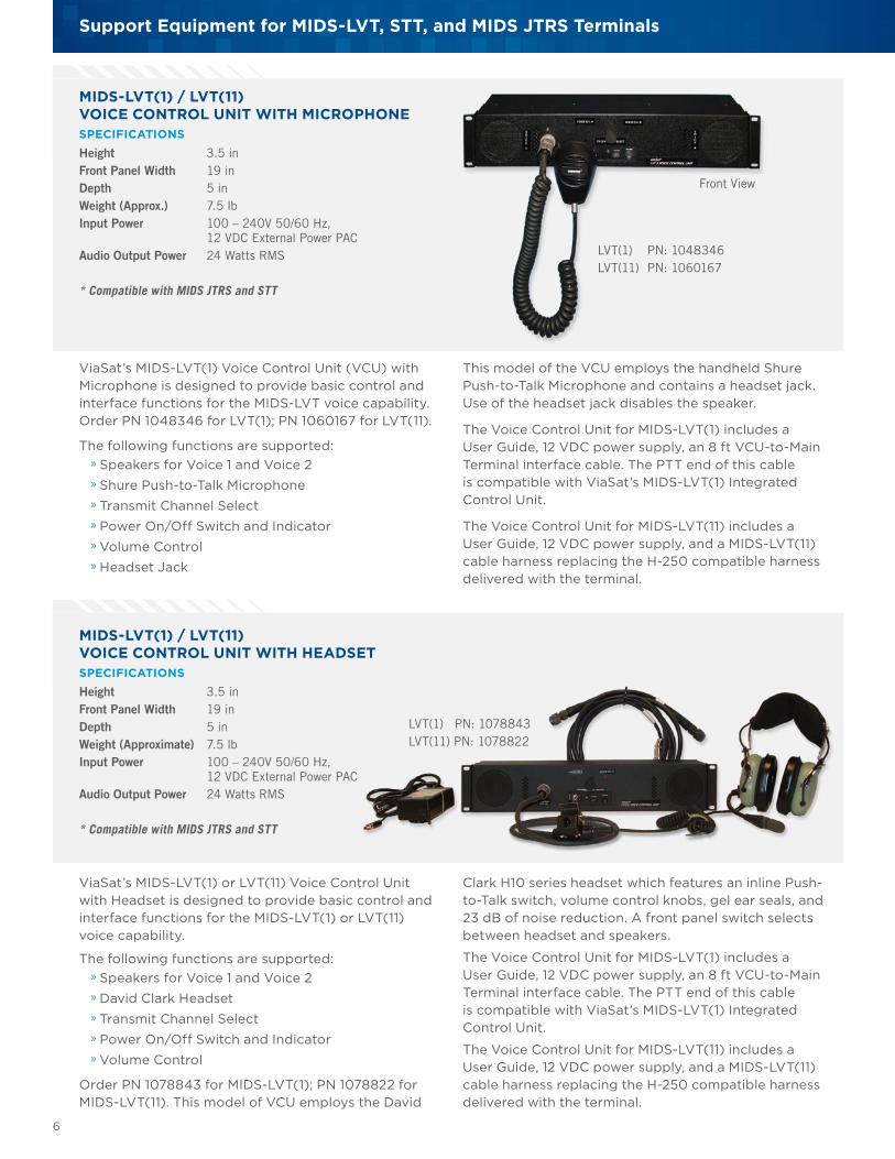
MIDS-LVT(1) / LVT(11) VOICE CONTROL UNIT WITH MICROPHONESPECIFICATIONS Height 3.5 in Front Panel Width 19 in Depth 5 in Weight (Approx.) 7.5 lbInput Power 100 – 240V 50/60 Hz, 12 VDC External Power PACAudio Output Power 24 Watts RMS
* Compatible with MIDS JTRS and STT
ViaSat’s MIDS-LVT(1) Voice Control Unit (VCU) with Microphone is designed to provide basic control and interface functions for the MIDS-LVT voice capability. Order PN 1048346 for LVT(1); PN 1060167 for LVT(11).
The following functions are supported: » Speakers for Voice 1 and Voice 2 » Shure Push-to-Talk Microphone » Transmit Channel Select » Power On/Off Switch and Indicator » Volume Control » Headset Jack
This model of the VCU employs the handheld Shure Push-to-Talk Microphone and contains a headset jack. Use of the headset jack disables the speaker.
The Voice Control Unit for MIDS-LVT(1) includes a User Guide, 12 VDC power supply, an 8 ft VCU-to-Main Terminal interface cable. The PTT end of this cable is compatible with ViaSat’s MIDS-LVT(1) Integrated Control Unit.
The Voice Control Unit for MIDS-LVT(11) includes a User Guide, 12 VDC power supply, and a MIDS-LVT(11) cable harness replacing the H-250 compatible harness delivered with the terminal.
MIDS-LVT(1) / LVT(11)VOICE CONTROL UNIT WITH HEADSET SPECIFICATIONS Height 3.5 in Front Panel Width 19 in Depth 5 in Weight (Approximate) 7.5 lbInput Power 100 – 240V 50/60 Hz, 12 VDC External Power PACAudio Output Power 24 Watts RMS
* Compatible with MIDS JTRS and STT
ViaSat’s MIDS-LVT(1) or LVT(11) Voice Control Unit with Headset is designed to provide basic control and interface functions for the MIDS-LVT(1) or LVT(11) voice capability.
The following functions are supported: » Speakers for Voice 1 and Voice 2 » David Clark Headset » Transmit Channel Select » Power On/Off Switch and Indicator » Volume Control
Order PN 1078843 for MIDS-LVT(1); PN 1078822 for MIDS-LVT(11). This model of VCU employs the David
Clark H10 series headset which features an inline Push-to-Talk switch, volume control knobs, gel ear seals, and 23 dB of noise reduction. A front panel switch selects between headset and speakers.
The Voice Control Unit for MIDS-LVT(1) includes a User Guide, 12 VDC power supply, an 8 ft VCU-to-Main Terminal interface cable. The PTT end of this cable is compatible with ViaSat’s MIDS-LVT(1) Integrated Control Unit.
The Voice Control Unit for MIDS-LVT(11) includes a User Guide, 12 VDC power supply, and a MIDS-LVT(11) cable harness replacing the H-250 compatible harness delivered with the terminal.
Front View
LVT(1) PN: 1048346LVT(11) PN: 1060167
LVT(1) PN: 1078843LVT(11) PN: 1078822
7
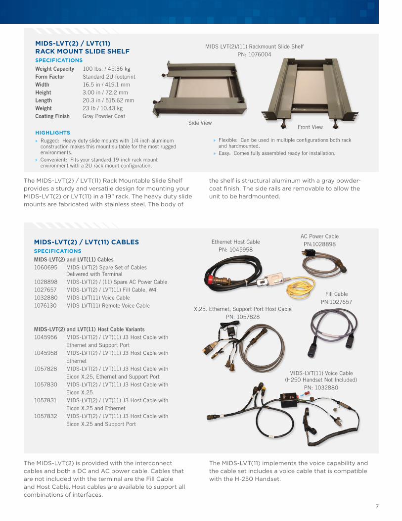
MIDS-LVT(2) / LVT(11) RACK MOUNT SLIDE SHELFSPECIFICATIONS Weight Capacity 100 lbs. / 45.36 kgForm Factor Standard 2U footprint Width 16.5 in / 419.1 mmHeight 3.00 in / 72.2 mmLength 20.3 in / 515.62 mmWeight 23 lb / 10.43 kgCoating Finish Gray Powder Coat
HIGHLIGHTS » Rugged: Heavy duty slide mounts with 1/4 inch aluminum construction makes this mount suitable for the most rugged environments.
» Convenient: Fits your standard 19-inch rack mount environment with a 2U rack mount configuration.
The MIDS-LVT(2) / LVT(11) Rack Mountable Slide Shelf provides a sturdy and versatile design for mounting your MIDS-LVT(2) or LVT(11) in a 19” rack. The heavy duty slide mounts are fabricated with stainless steel. The body of
Fill CablePN:1027657
Ethernet Host CablePN: 1045958
AC Power CablePN:1028898MIDS-LVT(2) / LVT(11) CABLES
SPECIFICATIONS MIDS-LVT(2) and LVT(11) Cables 1060695 MIDS-LVT(2) Spare Set of Cables Delivered with Terminal1028898 MIDS-LVT(2) / (11) Spare AC Power Cable1027657 MIDS-LVT(2) / LVT(11) Fill Cable, W41032880 MIDS-LVT(11) Voice Cable1076130 MIDS-LVT(11) Remote Voice Cable
MIDS-LVT(2) and LVT(11) Host Cable Variants1045956 MIDS-LVT(2) / LVT(11) J3 Host Cable with Ethernet and Support Port1045958 MIDS-LVT(2) / LVT(11) J3 Host Cable with Ethernet1057828 MIDS-LVT(2) / LVT(11) J3 Host Cable with Eicon X.25, Ethernet and Support Port1057830 MIDS-LVT(2) / LVT(11) J3 Host Cable with Eicon X.251057831 MIDS-LVT(2) / LVT(11) J3 Host Cable with Eicon X.25 and Ethernet1057832 MIDS-LVT(2) / LVT(11) J3 Host Cable with Eicon X.25 and Support Port
The MIDS-LVT(2) is provided with the interconnect cables and both a DC and AC power cable. Cables that are not included with the terminal are the Fill Cable and Host Cable. Host cables are available to support all combinations of interfaces.
The MIDS-LVT(11) implements the voice capability and the cable set includes a voice cable that is compatible with the H-250 Handset.
X.25. Ethernet, Support Port Host CablePN: 1057828
MIDS-LVT(11) Voice Cable (H250 Handset Not Included)
PN: 1032880
MIDS LVT(2)/(11) Rackmount Slide ShelfPN: 1076004
Front ViewSide View
» Flexible: Can be used in multiple configurations both rack and hardmounted.
» Easy: Comes fully assembled ready for installation.
the shelf is structural aluminum with a gray powder-coat finish. The side rails are removable to allow the unit to be hardmounted.
Support Equipment for MIDS-LVT, STT, and MIDS JTRS Terminals
8
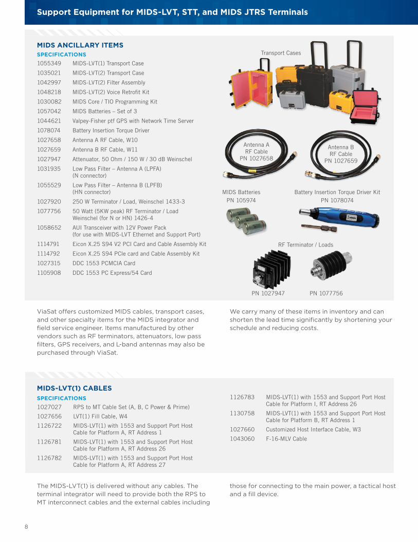
MIDS ANCILLARY ITEMSSPECIFICATIONS 1055349 MIDS-LVT(1) Transport Case
1035021 MIDS-LVT(2) Transport Case
1042997 MIDS-LVT(2) Filter Assembly
1048218 MIDS-LVT(2) Voice Retrofit Kit
1030082 MIDS Core / TIO Programming Kit
1057042 MIDS Batteries – Set of 3
1044621 Valpey-Fisher ptf GPS with Network Time Server
1078074 Battery Insertion Torque Driver
1027658 Antenna A RF Cable, W10
1027659 Antenna B RF Cable, W11
1027947 Attenuator, 50 Ohm / 150 W / 30 dB Weinschel
1031935 Low Pass Filter – Antenna A (LPFA) (N connector)
1055529 Low Pass Filter – Antenna B (LPFB) (HN connector)
1027920 250 W Terminator / Load, Weinschel 1433-3
1077756 50 Watt (5KW peak) RF Terminator / Load Weinschel (for N or HN) 1426-4
1058652 AUI Transceiver with 12V Power Pack (for use with MIDS-LVT Ethernet and Support Port)
1114791 Eicon X.25 S94 V2 PCI Card and Cable Assembly Kit
1114792 Eicon X.25 S94 PCle card and Cable Assembly Kit
1027315 DDC 1553 PCMCIA Card
1105908 DDC 1553 PC Express/54 Card
ViaSat offers customized MIDS cables, transport cases, and other specialty items for the MIDS integrator and field service engineer. Items manufactured by other vendors such as RF terminators, attenuators, low pass filters, GPS receivers, and L-band antennas may also be purchased through ViaSat.
The MIDS-LVT(1) is delivered without any cables. The terminal integrator will need to provide both the RPS to MT interconnect cables and the external cables including
MIDS-LVT(1) CABLES
MIDS BatteriesPN 105974
Battery Insertion Torque Driver KitPN 1078074
RF Terminator / Loads
We carry many of these items in inventory and can shorten the lead time significantly by shortening your schedule and reducing costs.
those for connecting to the main power, a tactical host and a fill device.
Transport Cases
Antenna B RF Cable
PN 1027659
Antenna A RF Cable
PN 1027658
SPECIFICATIONS 1027027 RPS to MT Cable Set (A, B, C Power & Prime)
1027656 LVT(1) Fill Cable, W4
1126722 MIDS-LVT(1) with 1553 and Support Port Host Cable for Platform A, RT Address 1
1126781 MIDS-LVT(1) with 1553 and Support Port Host Cable for Platform A, RT Address 26
1126782 MIDS-LVT(1) with 1553 and Support Port Host Cable for Platform A, RT Address 27
PN 1077756
1126783 MIDS-LVT(1) with 1553 and Support Port Host Cable for Platform I, RT Address 26
1130758 MIDS-LVT(1) with 1553 and Support Port Host Cable for Platform B, RT Address 1
1027660 Customized Host Interface Cable, W3
1043060 F-16-MLV Cable
PN 1027947
9
LEGS, TE, orOther Support
Port Application
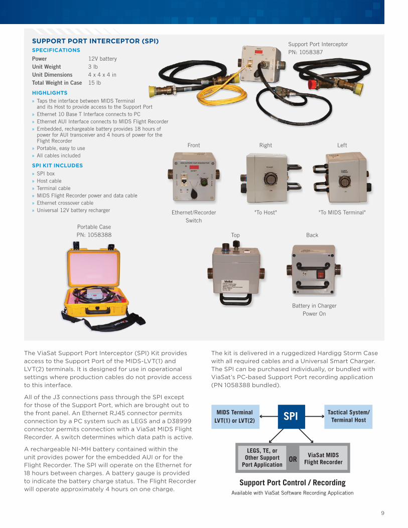
The kit is delivered in a ruggedized Hardigg Storm Case with all required cables and a Universal Smart Charger. The SPI can be purchased individually, or bundled with ViaSat’s PC-based Support Port recording application (PN 1058388 bundled).
SUPPORT PORT INTERCEPTOR (SPI)SPECIFICATIONSPower 12V batteryUnit Weight 3 lbUnit Dimensions 4 x 4 x 4 inTotal Weight in Case 15 lb
HIGHLIGHTS » Taps the interface between MIDS Terminal and its Host to provide access to the Support Port
» Ethernet 10 Base T Interface connects to PC » Ethernet AUI Interface connects to MIDS Flight Recorder » Embedded, rechargeable battery provides 18 hours of power for AUI transceiver and 4 hours of power for the Flight Recorder
» Portable, easy to use » All cables included
SPI KIT INCLUDES » SPI box » Host cable » Terminal cable » MIDS Flight Recorder power and data cable » Ethernet crossover cable » Universal 12V battery recharger
The ViaSat Support Port Interceptor (SPI) Kit provides access to the Support Port of the MIDS-LVT(1) and LVT(2) terminals. It is designed for use in operational settings where production cables do not provide access to this interface.
All of the J3 connections pass through the SPI except for those of the Support Port, which are brought out to the front panel. An Ethernet RJ45 connector permits connection by a PC system such as LEGS and a D38999 connector permits connection with a ViaSat MIDS Flight Recorder. A switch determines which data path is active.
A rechargeable NI-MH battery contained within the unit provides power for the embedded AUI or for the Flight Recorder. The SPI will operate on the Ethernet for 18 hours between charges. A battery gauge is provided to indicate the battery charge status. The Flight Recorder will operate approximately 4 hours on one charge.
Ethernet/Recorder Switch
Front
"To Host"
Right
Battery in ChargerPower On
Back
"To MIDS Terminal"
Left
TopPortable CasePN: 1058388
Support Port InterceptorPN: 1058387
Support Port Control / RecordingAvailable with ViaSat Software Recording Application
MIDS TerminalLVT(1) or LVT(2)
Tactical System/Terminal HostSPI
ViaSat MIDSFlight RecorderOR
Support Equipment for MIDS-LVT, STT, and MIDS JTRS Terminals
10
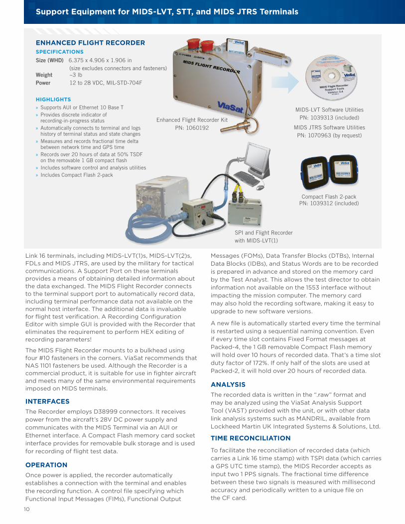
ENHANCED FLIGHT RECORDERSPECIFICATIONS Size (WHD) 6.375 x 4.906 x 1.906 in (size excludes connectors and fasteners) Weight ~3 lbPower 12 to 28 VDC, MIL-STD-704F
HIGHLIGHTS » Supports AUI or Ethernet 10 Base T » Provides discrete indicator of recording-in-progress status
» Automatically connects to terminal and logs history of terminal status and state changes
» Measures and records fractional time delta between network time and GPS time
» Records over 20 hours of data at 50% TSDF on the removable 1 GB compact flash
» Includes software control and analysis utilities » Includes Compact Flash 2-pack
Link 16 terminals, including MIDS-LVT(1)s, MIDS-LVT(2)s, FDLs and MIDS JTRS, are used by the military for tactical communications. A Support Port on these terminals provides a means of obtaining detailed information about the data exchanged. The MIDS Flight Recorder connects to the terminal support port to automatically record data, including terminal performance data not available on the normal host interface. The additional data is invaluable for flight test verification. A Recording Configuration Editor with simple GUI is provided with the Recorder that eliminates the requirement to perform HEX editing of recording parameters!
The MIDS Flight Recorder mounts to a bulkhead using four #10 fasteners in the corners. ViaSat recommends that NAS 1101 fasteners be used. Although the Recorder is a commercial product, it is suitable for use in fighter aircraft and meets many of the same environmental requirements imposed on MIDS terminals.
INTERFACESThe Recorder employs D38999 connectors. It receives power from the aircraft’s 28V DC power supply and communicates with the MIDS Terminal via an AUI or Ethernet interface. A Compact Flash memory card socket interface provides for removable bulk storage and is used for recording of flight test data.
OPERATIONOnce power is applied, the recorder automatically establishes a connection with the terminal and enables the recording function. A control file specifying which Functional Input Messages (FIMs), Functional Output
Messages (FOMs), Data Transfer Blocks (DTBs), Internal Data Blocks (IDBs), and Status Words are to be recorded is prepared in advance and stored on the memory card by the Test Analyst. This allows the test director to obtain information not available on the 1553 interface without impacting the mission computer. The memory card may also hold the recording software, making it easy to upgrade to new software versions.
A new file is automatically started every time the terminal is restarted using a sequential naming convention. Even if every time slot contains Fixed Format messages at Packed-4, the 1 GB removable Compact Flash memory will hold over 10 hours of recorded data. That’s a time slot duty factor of 172%. If only half of the slots are used at Packed-2, it will hold over 20 hours of recorded data.
ANALYSISThe recorded data is written in the “.raw” format and may be analyzed using the ViaSat Analysis Support Tool (VAST) provided with the unit, or with other data link analysis systems such as MANDRIL, available from Lockheed Martin UK Integrated Systems & Solutions, Ltd.
TIME RECONCILIATION
To facilitate the reconciliation of recorded data (which carries a Link 16 time stamp) with TSPI data (which carries a GPS UTC time stamp), the MIDS Recorder accepts as input two 1 PPS signals. The fractional time difference between these two signals is measured with millisecond accuracy and periodically written to a unique file on the CF card.
MIDS-LVT Software UtilitiesPN: 1039313 (included)
MIDS JTRS Software UtilitiesPN: 1070963 (by request)
Compact Flash 2-pack PN: 1039312 (included)
SPI and Flight Recorder with MIDS-LVT(1)
Enhanced Flight Recorder KitPN: 1060192
11
ViaSat has a turnkey solution for employing the ViaSat-Harris Small Tactical Terminal (STT) KOR-24 in a ground or lab environment! The STT implements UHF, VHF and Link 16. The Control and Interface Unit (CIU) is a rack mountable enclosure providing all power, cooling, cabling, and control functions needed to operate the STT. Insert the terminal directly into the integrated Fan Tray and lock it in place with ARINC fasteners. Connect the cables provided to the front of the STT and the rear
panel of the CIU, routing them through the cable tray below the front panel. Turn the master Power ON/OFF switch on the rear of the unit and you’re ready to begin operations! The master ON/OFF switch provides 28V DC power to the STT and all components of the CIU. A Power On Indicator illuminates when power is applied. Separate On/Off switches control each channel. An embedded PCB converts a 5V or 10V GPS 1 PPS signal to the 5V Differential signal required by the STT.
STT CABLES AND ACCESSORIES (AVAILABLE SEPARATELY) » 1117277 STT Link 16 (RF) Antenna A Cable (W8) – 1 meter cable terminating SMA(m) connector suitable for interfacing to other connectors
» 1117279 STT Link 16 (RF) Antenna B Cable (W9) – 1 meter cable terminating SMA(m) connector suitable for interfacing to other connectors
» 1124366 STT Mating Connector Kit Set of Mating Connectors for the STT: J1, J2, J3, J4, J5, J6, J7, J10
» 1117574 STT Fan Tray (Sheet Metal) for the STT Includes Power Cable
» 1118069 Falcon III Keypad Display Unit (KDU) for controlling the STT UHF/VHF Channels
» 1142642 2U STT Voice Control Unit (with Microphone)
» 1142643 1U STT Voice Control Unit (with Microphone)
» 1142644 2U STT Voice Control Unit (with Headset)
» 1142645 1U STT Voice Control Unit (with Headset)
» 11044621 ptf GPS with Network Time Server the provides 1 PPS signal suitable for use as ETR to STT Terminals. GPS Antenna and 100 foot cable included.
» VA-022801-9000 LEGS Full-up System with Ethernet implements the platform interface employed by STT.
ViaSat PN 1117279 STT Antenna “B”(W-9)
Cable Assy
ViaSat PN 1117277 STT Antenna “A”(W-8)
Cable Assy
SMAConnector
SMAConnector
Riveted Model PN 1117574STT FAN TRAY ASSY
Rear
FrontSide
ANTENNA CABLES
STT Control and Interface UnitPN: 1115296
STT Not Included
Front
Rear
STT CONTROL AND INTERFACE UNIT (CIU)The STT Control and Interface Unit (CIU) provides everything needed to operate the ViaSat/Harris Small Tactical Terminal (STT) KOR-24.All interconnect cables:
» Integrated power supply with Master Power On/Off
» Integrated Fan Tray
» Integrated Keypad/Display Unit (KDU) switchable between Channel 1 and Channel 2
» Indicators for Channel 1 Fail, Channel 2 Fail, and Link 16 Fail
» Access to Host interfaces
» Access to Voice interfaces
» Link 16 Discretes: Zeroize, Long Term Transmit Inhibit (LTTI), and IFF Emergency
» Access to Link 16 transmit signals and suppression discretes (both differential and single-ended)
» Conversion of GPS ETR 5V, 10V to Differential Signal as required by STT
Support Equipment for MIDS-LVT, STT, and MIDS JTRS Terminals
12
POWER, COOLING, CONTROL, AND ACCESSORIES FOR MIDS JTRSSPECIFICATIONS
MIDS JTRS CABLES 1052414 RPS-MT W105 B Power
1052382 RPS-MT W112 C Power (Interchangelable with MIDS-LVT W12)
1052380 MIDS JTRS W104 Fill Cable (Interchangelable with MIDS-LVT W4)
1048766 MIDS JTRS W103 Host Cable with 1553 and Ethernet for Platform A, RT Address 1
1126528 JTRS HMI Bus, J16 Cable
1126394 MIDS JTRS Pass Through Cable (Provides Access to Support Port)
MIDS JTRS CAN BE USED WITH THE FOLLOWING ITEMS 1027226 MIDS-LVT(1) Cooling Tray Unit (115VAC 60 Hz)
1027984 MIDS-LVT(1) Cooling Tray Unit (230VAC 50 Hz-Euro)
1035372 MIDS-LVT(1) Control Plug, J7
1111689 MIDS-LVT(1) VCU with Microphone, 1U
1048346 MIDS-LVT(1) VCU with Microphone, 2U
1078843 MIDS-LVT(1) VCU with Headset, 2U
1060192 Enhanced MIDS Flight Recorder (Fighter-Qualified)
1036848 MIDS Power Unit
1095983 MIDS 1U Rackmountable Power Unit
1060032 MIDS-LVT(1) Integrated Control Unit (Can be customized for MIDS JTRS)
GPS Receiver provides 1 PPS signal suitable for use as ETR to MIDS, MIDS JTRS, and STT terminals. GPS antenna and cable included.
GPS NETWORK TIME SERVERSPECIFICATIONS Part Number 1044621
Dimensions 1U x 19 in x 12 in
Relative Humidity 0-95% (non-cond.) in.
Valpey-Fisher ptf GPS with Network Time Server PN: 11044621
» GPS Tracking: 12 parallel channels » Acquisition Time: <1.5 minutes (warm start) » Accuracy (1 PPS): <20ns » Holdover: <0.2 micro seconds/day (Rb opt) » 100/10 Base T Ethernet
» NTP Telnet, TCP/IP, FTP » Monitor/Control I/F » Alarm indicator and output » GPS Antenna and 100 ft. Cable included » 1 PPS: 10V, 5V and 5V Differential
Control PlugPN: 1035372
MIDS-LVT(1) Cooling Tray PN: 1027226 (115VAC)PN: 1027984 (230VAC)
Enhanced Flight RecorderPN: 1060192
MIDS-LVT(1) Power UnitPN: 1036848
MIDS 1U Rackmountable Power Unit PN: 1095983
MIDS-LVT(1) Voice Control Unit with Microphone LVT(1) PN: 1048346
MIDS-LVT(1) Voice Control Unit with Headset LVT(1) PN: 1078843
13
RF NETWORKSPECIFICATIONS Part Number 1028051 1036073
Height 2.0 in. 3.5 in.
Width 7.0 in. 9 in.
Depth 7.0 in. 8.0 in.
Weight (Approx.) 3.5 lbs. 5.5 lbs.
RF Cables and attenuators are not included.
The RF Network Unit permits multiple RF devices to be hubbed together in a network. It is intended for lab usage and operates over a frequency range of 0 to 2 GHz. There are 6 Type N female RF low level (1 watt) connectors on the chassis and a variable step attenuator that ranges between 0 and 110 dB in 1-dB steps.
An L-Band antenna is required to transmit Link 16 over the air. ViaSat recommends the high gain XVO 7-960-1215/1120 omni antenna made by European Antennas. This antenna covers the Link 16 band, 960 to 1215 MHz, and has a 7 dBi gain, nearly doubling the range of a system. Receive sensitivity – usually the limiting factor for communications with distant airborne platforms – is increased significantly. The antenna is lightweight (1.7 kg) and has an has an alloy base plate with 4 Stainless Steel bolts, a 1-inch offset spigot, and M16 Stainless Steel bolt and washers.
Mounting pole and guy wires are not included.
PN: 1028051
PN: 1036073
L-BAND GROUND ANTENNASPECIFICATIONS Weight 3.75 lbDimensions 40 x 3 in (1029 mm x 76.2 mm)
HIGHLIGHTS » L-band 960-1215 MHz » Gain 7 dBi
» Operating Temperature -40° C to +50° C
Be prepared! Armed with the 5-pound ViaSat Portable Antenna, a field service engineer, training instructor, or test engineer can conduct limited ground-to-air tests in the field. This L-band blade antenna is delivered with a 52-inch tripod and features a quick-connect mounting shoe that holds the antenna plate. It can be used in testing related to all L-band applications and is packaged in an expandable, zippered nylon bag.
The RF Network has an approximate 14 dB insertion loss between ports, and is perfect for bench-top or field use. Included with the unit are four 50-Ohm terminations for use on unused RF ports. The RF Network is available in a 19-inch rackmount model and a portable model measuring just 7 in. x 7 in. x 2 in; small enough to fit in a field service kit.
PORTABLE ANTENNASPECIFICATIONS Weight 5 lbDimensions 24 x 8 in (in bag)
HIGHLIGHTS » L-band 960-1220 MHz » 2500 watts at 50,000 ft. » Lightweight metal tripod
RF ANTENNA CABLESSPECIFICATIONS RF Cables 1003220 RF Antenna Cable, 50 ft Heliax1100541 RF Antenna Cable, 50 ft RG-214 double-shielded
PN: 1044620
PN: 1058390
RF Antenna Cable, Outdoor NM-NM 50 ft Heliax with 2.34 dB of loss per 100 ft. DC-18 GHz, 1900 watts max
RF Antenna Cable, Outdoor NM-NM 50 ft RG-214 double-shielded with 8 dB of loss per 100 ft.
Support Equipment for MIDS-LVT, STT, and MIDS JTRS Terminals
14
Link 16 Environment Gateway Stimulator (LEGS) is an essential MIDS support tool. Prime developers use this software in the integration of MIDS terminals, and ground facilities and Field Service Engineers rely on the LEGS application for terminal troubleshooting and maintenance, The tool is also used by test facilities for Link 16 system performance measurement and evaluation, and by instructors for MIDS training.
A low-cost version (LEGS-Lite) that does not include the scenario generation or situation display capabilities
ViaSat’s Link 16 Flight-line Tool (LiFT) software is designed to support “go/no-go” testing and troubleshooting of Multifunctional Information Distribution System Low Volume Terminals (MIDS-LVT) in a field environment. The LiFT application is available installed on a Tablet PC or as a software package for
is also available. The J LEGS version of the application implements the JTRS Platform A interface and is available to U.S. Customers.
ViaSat can tailor LEGS Remote Interface Modules (RIMs) to support your special requirements. We have developed RIMs for GPS testing, ETR testing, OTAR testing, Voice testing, and Navigation Testing. And, we have an API to support automated testing using products such as LabView and VEF-Pro. An ICD is available by special request. If you have special needs, let us know.
customers who want to install the LiFT application on their own equipment, such as the GoBook 3.
This software is intended for use by technicians and allows the user to read, reconfigure, update, and monitor terminal parameters. Data is provided in dynamic graphical displays.
Licenses are available for installation on customer-furnished equipment after initial purchase.
LINK 16 ENVIRONMENT GATEWAY STIMULATOR (LEGS)HIGHLIGHTS » Terminal Initialization Control » Terminal Status Monitoring » Detailed Recording » MIDS Re-programmer » Scenario Generation » Situation Awareness » Gateway to up to 8 Client Applications
» Multi-Terminal Control
SUPPORTED TERMINAL TYPES » MIDS LVT(1) Platform A, B, D, I and Support Port » MIDS LVT(2) X.25, Plaform J, JREAP-C and
Support Port » MIDS on Ship (MOS) Platform M and Support Port » MIDS LVT(3) FDL and Support Port » Class 2 Navy Shipboard, Navy Airborne, Army 2M,
and USAF F-15LEGS-LITE » A low-cost version of the LEGS software that does not include the scenario generation or situation display capabilities is available.
LINK 16 FLIGHT-LINE TOOL (LIFT)HIGHLIGHTS » Obtain Terminal Status: IPF Fail, TDMA Rcv/Tx Fail, TDMA
Degraded, Thermal Overload and Sanitization Confirmation
» Initiate Built-In Test (IBIT)
» View SDU Alert Status
» View Position Data
» View Cockpit ID
» Modify a Limited Number of Settings: Set/Change CCPD, STN, NTR, Time, Tx Mode, Output Power Mode, TACAN Settings and Voice Channel
» Load an Initialization File
» Start Net Entry
» Participate in a Network
» View 12-Sec Counters
» Observe Received RF Messages by Type » Exercise TACAN Function
» Sanitize Terminal for Shipment
PN: VA-022801-9000
PN: 1043057
PN: VA-022801-9500
PN 1043057 LiFT Handheld KitPN 1043058 Software License and CD
15
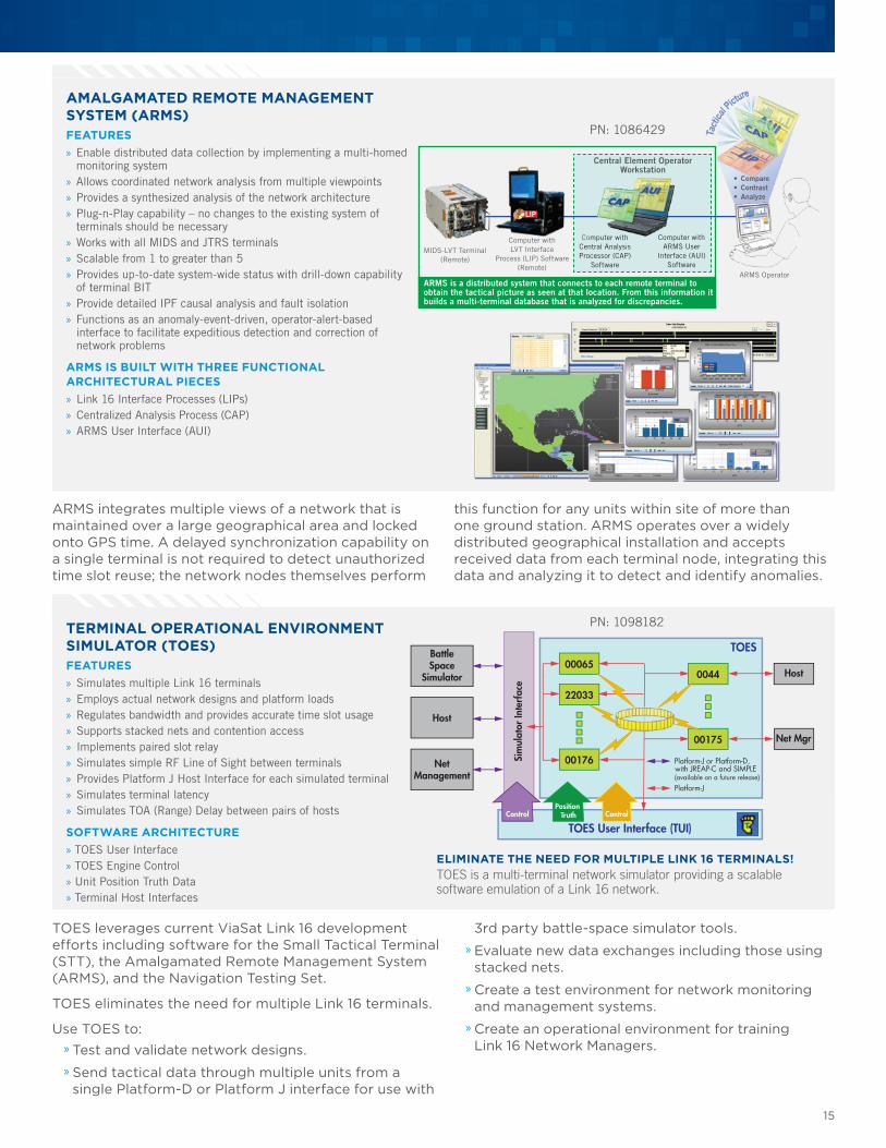
AMALGAMATED REMOTE MANAGEMENT SYSTEM (ARMS)FEATURES » Enable distributed data collection by implementing a multi-homed monitoring system
» Allows coordinated network analysis from multiple viewpoints » Provides a synthesized analysis of the network architecture » Plug-n-Play capability – no changes to the existing system of terminals should be necessary
» Works with all MIDS and JTRS terminals » Scalable from 1 to greater than 5 » Provides up-to-date system-wide status with drill-down capability of terminal BIT
» Provide detailed IPF causal analysis and fault isolation » Functions as an anomaly-event-driven, operator-alert-based interface to facilitate expeditious detection and correction of network problems
ARMS IS BUILT WITH THREE FUNCTIONAL ARCHITECTURAL PIECES » Link 16 Interface Processes (LIPs) » Centralized Analysis Process (CAP) » ARMS User Interface (AUI)
ARMS integrates multiple views of a network that is maintained over a large geographical area and locked onto GPS time. A delayed synchronization capability on a single terminal is not required to detect unauthorized time slot reuse; the network nodes themselves perform
MIDS-LVT Terminal(Remote)
Computer withLVT Interface
Process (LIP) Software(Remote)
Computer withCentral Analysis Processor (CAP)
Software
Computer withARMS User
Interface (AUI) Software
Central Element Operator Workstation
ARMS is a distributed system that connects to each remote terminal to obtain the tactical picture as seen at that location. From this information it builds a multi-terminal database that is analyzed for discrepancies.
ARMS Operator
• Compare• Contrast• Analyze
LIP
this function for any units within site of more than one ground station. ARMS operates over a widely distributed geographical installation and accepts received data from each terminal node, integrating this data and analyzing it to detect and identify anomalies.
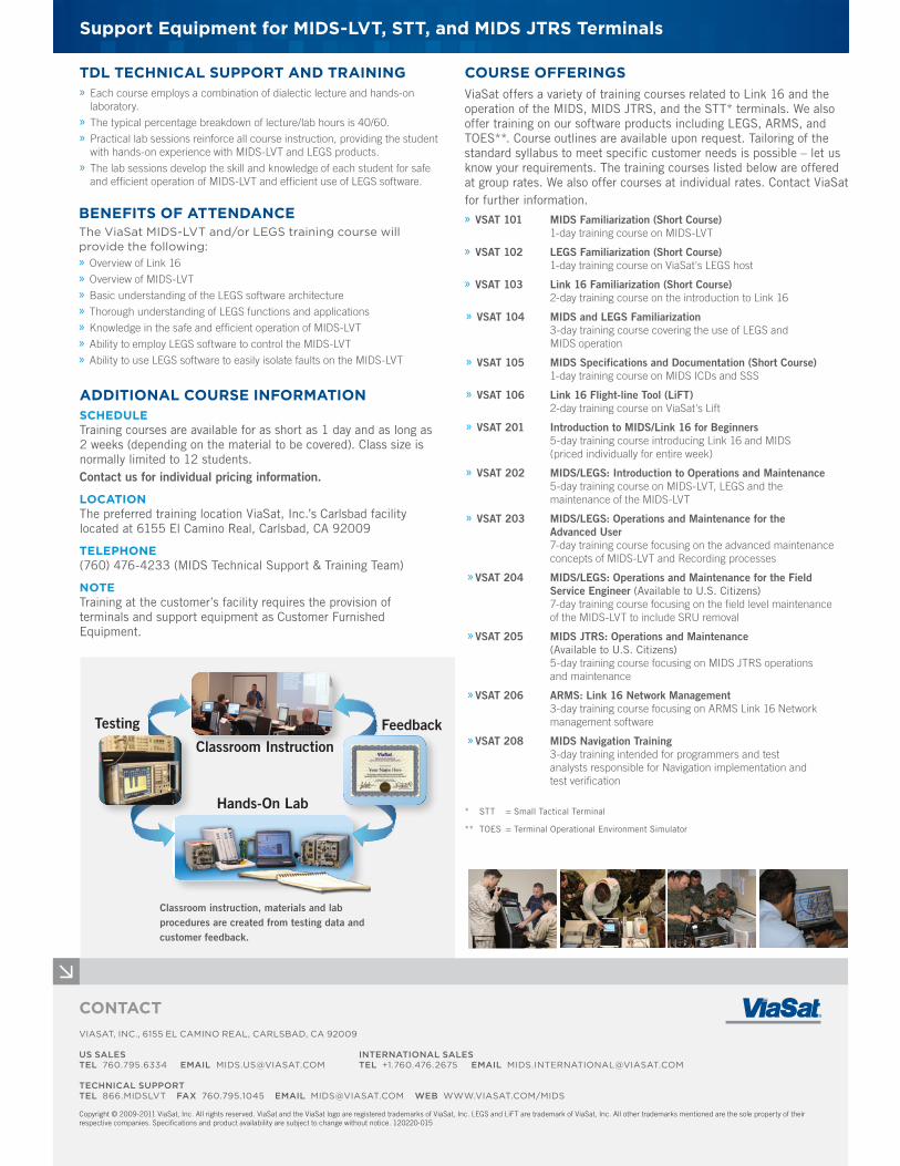
TOES is a multi-terminal network simulator providing a scalable software emulation of a Link 16 network.
TOES
TOES User Interface (TUI)Control
Sim
ulat
or In
terf
ace
Position Truth Control
Platform-J or Platform-D,
Platform-J
with JREAP-C and SIMPLE (available on a future release)
Host
Net Mgr
Host
BattleSpace
Simulator
NetManagement
00065
22033
00176
00175
0044
ELIMINATE THE NEED FOR MULTIPLE LINK 16 TERMINALS!
TOES leverages current ViaSat Link 16 development efforts including software for the Small Tactical Terminal (STT), the Amalgamated Remote Management System (ARMS), and the Navigation Testing Set.
TOES eliminates the need for multiple Link 16 terminals.
Use TOES to: » Test and validate network designs. » Send tactical data through multiple units from a single Platform-D or Platform J interface for use with
TERMINAL OPERATIONAL ENVIRONMENT SIMULATOR (TOES)FEATURES » Simulates multiple Link 16 terminals » Employs actual network designs and platform loads » Regulates bandwidth and provides accurate time slot usage » Supports stacked nets and contention access » Implements paired slot relay » Simulates simple RF Line of Sight between terminals » Provides Platform J Host Interface for each simulated terminal » Simulates terminal latency » Simulates TOA (Range) Delay between pairs of hosts
SOFTWARE ARCHITECTURE » TOES User Interface » TOES Engine Control » Unit Position Truth Data » Terminal Host Interfaces
3rd party battle-space simulator tools. » Evaluate new data exchanges including those using stacked nets. » Create a test environment for network monitoring and management systems. » Create an operational environment for training Link 16 Network Managers.
PN: 1098182
PN: 1086429
Support Equipment for MIDS-LVT, STT, and MIDS JTRS Terminals
ADDITIONAL COURSE INFORMATIONSCHEDULETraining courses are available for as short as 1 day and as long as 2 weeks (depending on the material to be covered). Class size is normally limited to 12 students.Contact us for individual pricing information.
LOCATIONThe preferred training location ViaSat, Inc.’s Carlsbad facility located at 6155 El Camino Real, Carlsbad, CA 92009
TELEPHONE(760) 476-4233 (MIDS Technical Support & Training Team)
NOTETraining at the customer’s facility requires the provision of terminals and support equipment as Customer Furnished Equipment.
BENEFITS OF ATTENDANCEThe ViaSat MIDS-LVT and/or LEGS training course will provide the following: » Overview of Link 16 » Overview of MIDS-LVT » Basic understanding of the LEGS software architecture » Thorough understanding of LEGS functions and applications » Knowledge in the safe and efficient operation of MIDS-LVT » Ability to employ LEGS software to control the MIDS-LVT » Ability to use LEGS software to easily isolate faults on the MIDS-LVT
COURSE OFFERINGSViaSat offers a variety of training courses related to Link 16 and the operation of the MIDS, MIDS JTRS, and the STT* terminals. We also offer training on our software products including LEGS, ARMS, and TOES**. Course outlines are available upon request. Tailoring of the standard syllabus to meet specific customer needs is possible – let us know your requirements. The training courses listed below are offered at group rates. We also offer courses at individual rates. Contact ViaSat for further information. » VSAT 101 MIDS Familiarization (Short Course) 1-day training course on MIDS-LVT
» VSAT 102 LEGS Familiarization (Short Course) 1-day training course on ViaSat's LEGS host
» VSAT 103 Link 16 Familiarization (Short Course) 2-day training course on the introduction to Link 16
» VSAT 104 MIDS and LEGS Familiarization 3-day training course covering the use of LEGS and MIDS operation
» VSAT 105 MIDS Specifications and Documentation (Short Course) 1-day training course on MIDS ICDs and SSS
» VSAT 106 Link 16 Flight-line Tool (LiFT) 2-day training course on ViaSat's Lift
» VSAT 201 Introduction to MIDS/Link 16 for Beginners 5-day training course introducing Link 16 and MIDS (priced individually for entire week)
» VSAT 202 MIDS/LEGS: Introduction to Operations and Maintenance 5-day training course on MIDS-LVT, LEGS and the maintenance of the MIDS-LVT
» VSAT 203 MIDS/LEGS: Operations and Maintenance for the Advanced User 7-day training course focusing on the advanced maintenance concepts of MIDS-LVT and Recording processes
» VSAT 204 MIDS/LEGS: Operations and Maintenance for the Field Service Engineer (Available to U.S. Citizens) 7-day training course focusing on the field level maintenance of the MIDS-LVT to include SRU removal
» VSAT 205 MIDS JTRS: Operations and Maintenance (Available to U.S. Citizens) 5-day training course focusing on MIDS JTRS operations and maintenance
» VSAT 206 ARMS: Link 16 Network Management 3-day training course focusing on ARMS Link 16 Network management software
» VSAT 208 MIDS Navigation Training 3-day training intended for programmers and test analysts responsible for Navigation implementation and test verification
TDL TECHNICAL SUPPORT AND TRAINING » Each course employs a combination of dialectic lecture and hands-on laboratory.
» The typical percentage breakdown of lecture/lab hours is 40/60. » Practical lab sessions reinforce all course instruction, providing the student with hands-on experience with MIDS-LVT and LEGS products.
» The lab sessions develop the skill and knowledge of each student for safe and efficient operation of MIDS-LVT and efficient use of LEGS software.
CONTACT VIASAT, INC., 6155 EL CAMINO REAL, CARLSBAD, CA 92009
US SALES INTERNATIONAL SALESTEL 760.795.6334 EMAIL [email protected] TEL +1.760.476.2675 EMAIL [email protected]
TECHNICAL SUPPORTTEL 866.MIDSLVT FAX 760.795.1045 EMAIL [email protected] WEB WWW.VIASAT.COM/MIDS
Copyright © 2009-2011 ViaSat, Inc. All rights reserved. ViaSat and the ViaSat logo are registered trademarks of ViaSat, Inc. LEGS and LiFT are trademark of ViaSat, Inc. All other trademarks mentioned are the sole property of their respective companies. Specifications and product availability are subject to change without notice. 120220-015
Classroom InstructionFeedbackTesting
Classroom instruction, materials and lab procedures are created from testing data and customer feedback.
Hands-On Lab* STT = Small Tactical Terminal
** TOES = Terminal Operational Environment Simulator