Embed Size (px)
Citation preview
IOSR Journal of Mechanical and Civil Engineering (IOSR-JMCE)
e-ISSN: 2278-1684,p-ISSN: 2320-334X, Volume 11, Issue 2 Ver. VIII (Mar- Apr. 2014), PP 52-78
www.iosrjournals.org
www.iosrjournals.org 52 | Page
Combined Core Pillar Concept for Earthquake Resistant
Building
Shubham Gupta Pursuing civil engineering from Galgotia’s College Of Engineering & Technology, greater noida(U.P) 201306-
India
Abstract : The main aim of this paper is to introduce “Combined Core Pillar Concept” for earthquake
resistant design of a building . A 12 storey building model of height 43m is taken in which this concept is
applied .All other methods which has been used in this model are - building with friction isolator (FI) , with
rubber bearing (RB) , with shearwall (fixed base), with shearwall having base as rubber bearing and
friction isolator, with cross bracing & with k-type bracing . A comparative study of the model with
these different techniques is done with the help of software SAP 2000.The method used for the
analysis is RESPONSE SPECTRUM METHOD . Here the design spectra recommended by Indian
Standard Code IS 1893-2002(PART I) is used. From comparative study the Combined Core Pillar concept
is found to be most effective.
I. Introduction The main challenge in earthquake resistant design is to reduce the earthquake forces so that an
economic & safe design of members of the structure can be done.Basically two criterias must be fulfilled the
strength criteria & the deflection criteria.To resist the earthquake forces many methods have been used in
buildings like use of shearwalls at appropriate positions in the buildings, use of bracings (cross bracing , k-
type bracing etc). In all these cases the value of base shear , base moments are high & according to
these values the different components of building are designed, obviously the sectional requirement of the
components in these cases are high to resist such high forces. Since in seismic analysis of a building base
shear is distributed to the different floors according to the floor heights & then these floor forces are
distributed among the lateral force resisting elements at that floor so if the base shear is high then the
sectional requirement of these components will also high.So to reduce the base shear & the inertia forces
induced in the structure due to earthquake, base isolation technique is frequently used in practice. In base
isolation technique the base of the structure is isolated so that the fundamental period of the structure is shifted
out of the dangerous resonance range & concentration of the deformation demand at the isolation system.
But I have used a different method to shift the fundamental period of the structure that is “COMBINED CORE
PILLAR CONCEPT” . So to compare response of building with different techniques used , a parametric
study on reinforced concrete (RC) building is done. For this purpose the different techniques used in a
same model are :
1. RC building model with fixed column base.
2. RC building model with Rubber bearing (RB)column base .
3. RC building model with friction isolated(FI) column base.
4. RC building model with shearwalls at corners having fixed base.
5. RC building model with shearwalls at corners with rubber bearings base.
6. RC building model with shearwalls at corners with friction isolator as base.
7. RC building model with cross bracings.
8. RC building model with k-type bracings.
9. RC building model with combined core pillar concept having hinged base of core steel column.
10. RC building model with combined core pillar concept having fixed base of core steel column.
Combined Core Pillar Concept for Earthquake Resistant Building
www.iosrjournals.org 53 | Page
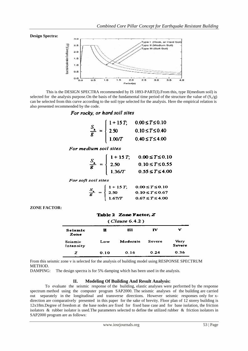
Design Spectra:
This is the DESIGN SPECTRA recommended by IS 1893-PART(I).From this, type II(medium soil) is
selected for the analysis purpose.On the basis of the fundamental time period of the structure the value of (Sa/g)
can be selected from this curve according to the soil type selected for the analysis. Here the empirical relation is
also presented recommended by the code.
ZONE FACTOR:
From this seismic zone v is selected for the analysis of building model using RESPONSE SPECTRUM
METHOD.
DAMPING: The design spectra is for 5% damping which has been used in the analysis.
II. Modeling Of Building And Result Analysis: To evaluate the seismic response of the building, elastic analyses were performed by the response
spectrum method using the computer program SAP2000. The seismic analyses of the building are carried
out separately in the longitudinal and transverse directions. However seismic responses only for x-
direction are comparatively presented in this paper for the sake of brevity. Floor plan of 12 storey building is
12x18m.Degree of freedom at the base nodes are fixed for fixed base case and for base isolation, the friction
isolators & rubber isolator is used.The parameters selected to define the utilized rubber & friction isolators in
SAP2000 program are as follows:
Combined Core Pillar Concept for Earthquake Resistant Building
www.iosrjournals.org 54 | Page
Non-linear link type: Rubber Bearing->
1. U1 linear effective stiffness = 1500000 KN/m
2. U2 & U3 linear effective stiffness: 800 KN/m
3. U2 & U3 nonlinear stiffness : 2500 KN/m
4. U2 & U3 yield strength : 80 KN
5. U2 & U3 post yield stiffness ratio: 0.1
Non-linear link type friction isolator->
1. U1 linear effective stiffness : 15000000 KN/m.
2. U2 & U3 non linear stiffness: 15000KN/m
3. U2 & U3 friction coefficient, slow: 0.03, fast:0.05
4. Rate parameter: 40
5. U2 & U3 radius of sliding surface: 2.23
Columns and beams are modeled with frame elements, slabs and structural walls are modeled with
shell elements. Slab has been considered as a rigid diaphragm in each storey level . In the analysis Young’s
modulus and the unit weight of concrete are taken to be 28000MPa and 25 KN/m3 respectively. The
damping ratio is assumed as 5% in all modes. The reference peak ground acceleration is taken to be .4g that is
recommended in IS code. Thus it is assumed that the building is suited in high seismicity zone. Seismic
analysis of the building accounting for the influence of the local ground conditions is carried out with the help of
the design spectra of IS code.
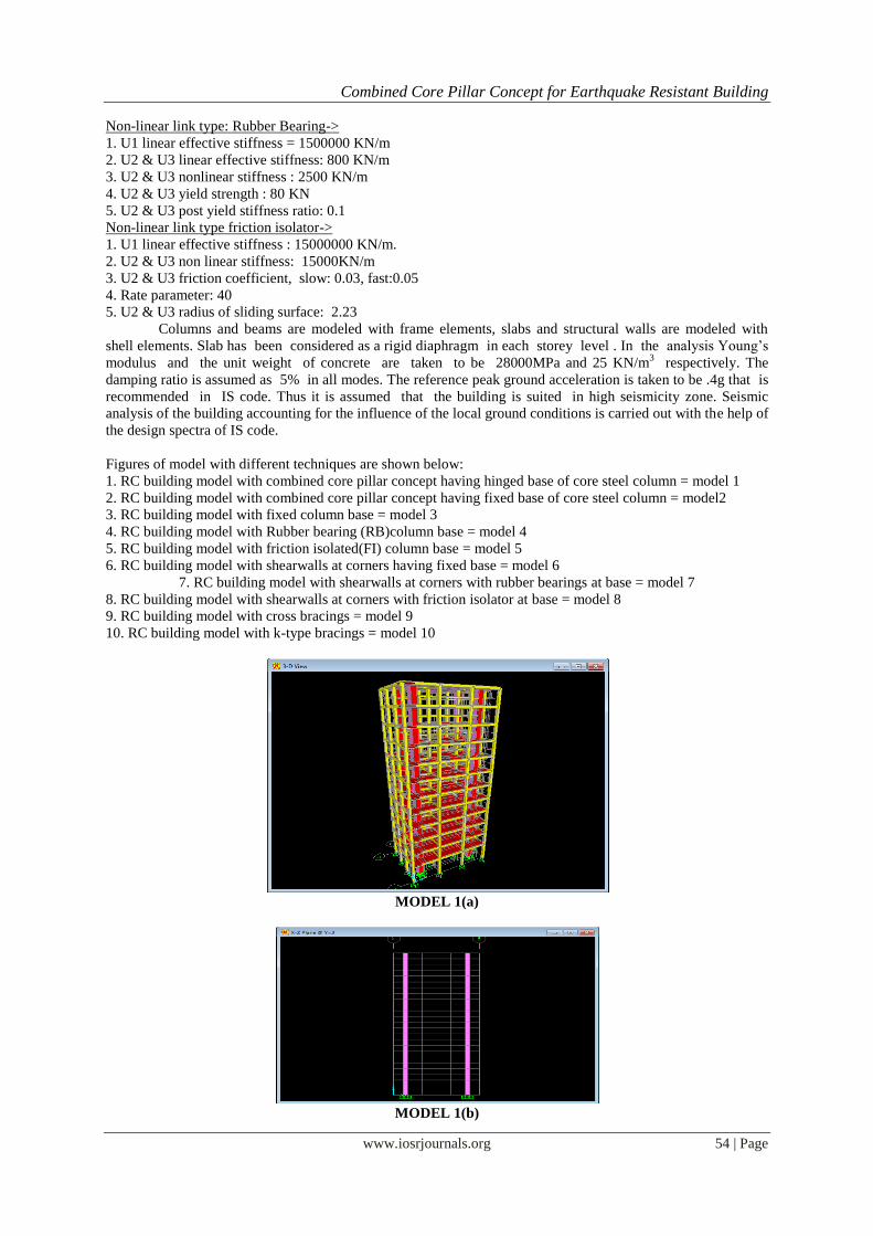
Figures of model with different techniques are shown below:
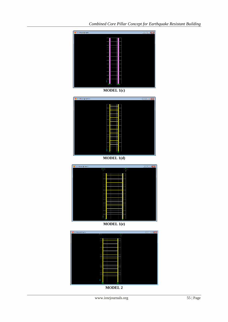
1. RC building model with combined core pillar concept having hinged base of core steel column = model 1
2. RC building model with combined core pillar concept having fixed base of core steel column = model2
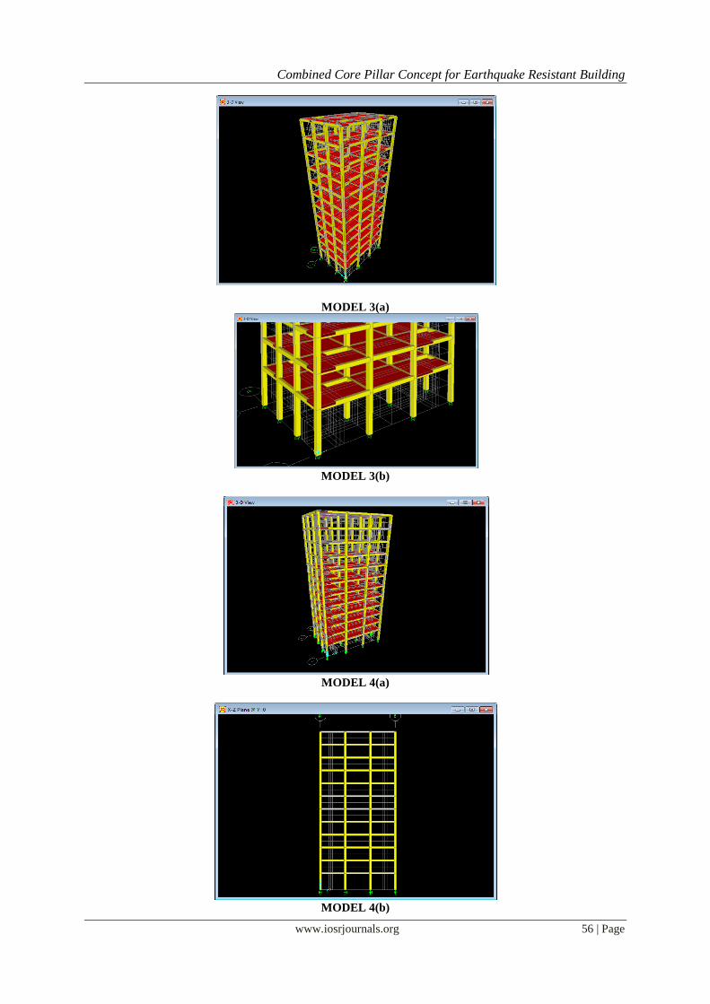
3. RC building model with fixed column base = model 3
4. RC building model with Rubber bearing (RB)column base = model 4
5. RC building model with friction isolated(FI) column base = model 5
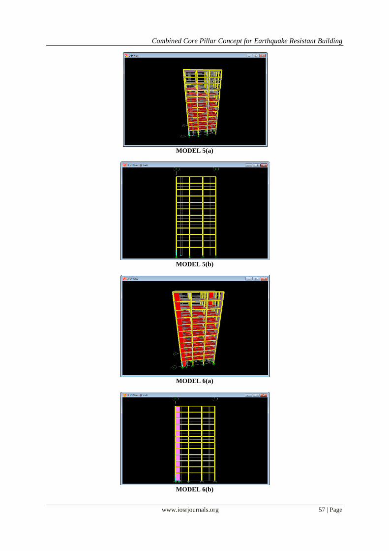
6. RC building model with shearwalls at corners having fixed base = model 6
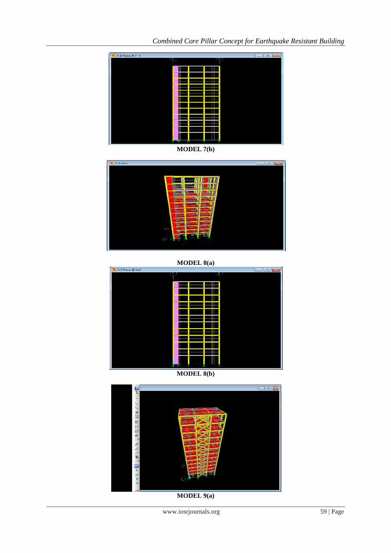
7. RC building model with shearwalls at corners with rubber bearings at base = model 7
8. RC building model with shearwalls at corners with friction isolator at base = model 8
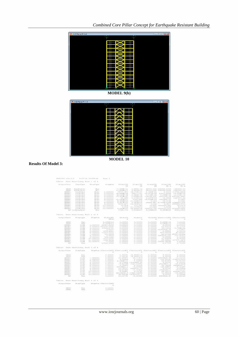
9. RC building model with cross bracings = model 9
10. RC building model with k-type bracings = model 10
MODEL 1(a)
MODEL 1(b)
Combined Core Pillar Concept for Earthquake Resistant Building
www.iosrjournals.org 55 | Page
MODEL 1(c)
MODEL 1(d)
MODEL 1(e)
MODEL 2
Combined Core Pillar Concept for Earthquake Resistant Building
www.iosrjournals.org 56 | Page
MODEL 3(a)
MODEL 3(b)
MODEL 4(a)
MODEL 4(b)
Combined Core Pillar Concept for Earthquake Resistant Building
www.iosrjournals.org 57 | Page
MODEL 5(a)
MODEL 5(b)
MODEL 6(a)
MODEL 6(b)
Combined Core Pillar Concept for Earthquake Resistant Building
www.iosrjournals.org 58 | Page
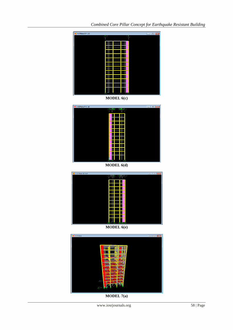
MODEL 6(c)
MODEL 6(d)
MODEL 6(e)
MODEL 7(a)
Combined Core Pillar Concept for Earthquake Resistant Building
www.iosrjournals.org 59 | Page
MODEL 7(b)
MODEL 8(a)
MODEL 8(b)
MODEL 9(a)
Combined Core Pillar Concept for Earthquake Resistant Building
www.iosrjournals.org 60 | Page
MODEL 9(b)
MODEL 10
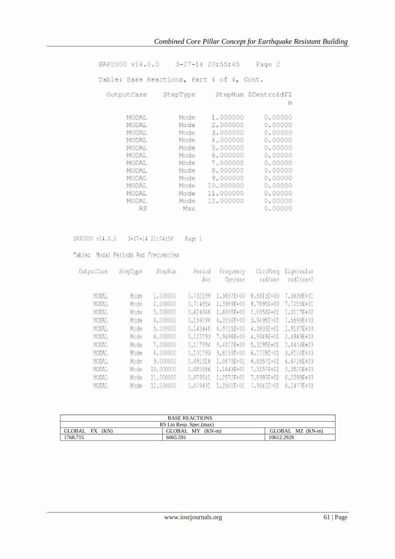
Results Of Model 3:
Combined Core Pillar Concept for Earthquake Resistant Building
www.iosrjournals.org 61 | Page
BASE REACTIONS
RS Lin Resp. Spec.(max)
GLOBAL FX (KN) GLOBAL MY (KN-m) GLOBAL MZ (KN-m)
1768.715 6065.591 10612.2928
Combined Core Pillar Concept for Earthquake Resistant Building
www.iosrjournals.org 62 | Page
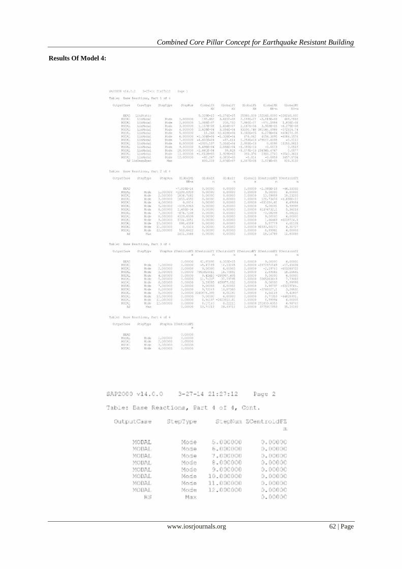
Results Of Model 4:
Combined Core Pillar Concept for Earthquake Resistant Building
www.iosrjournals.org 63 | Page
BASE REACTIONS
RS Lin Resp. spec.(max)
GLOBAL FX (KN) GLOBAL MY (KN-m) GLOBAL MZ(KN-m)
400.226 826.313 2401.356
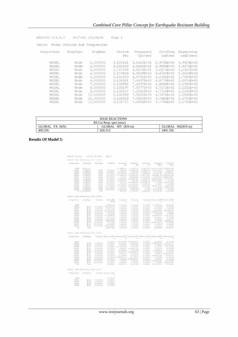
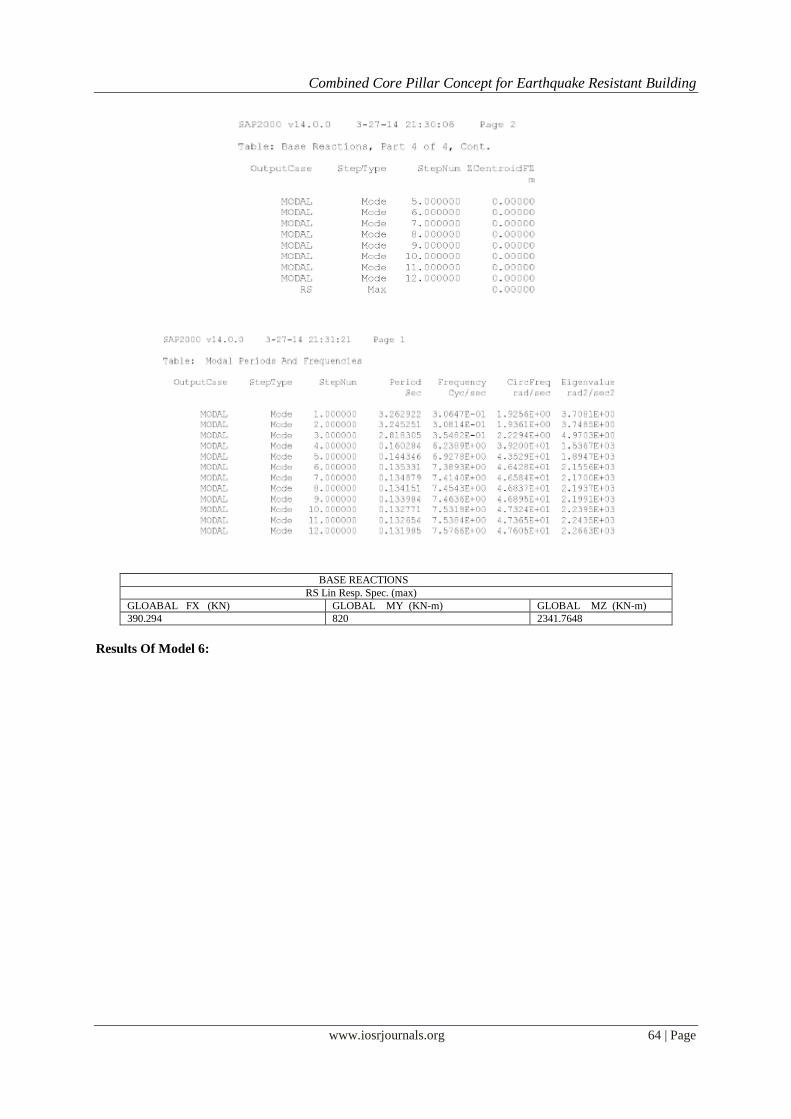
Results Of Model 5:
Combined Core Pillar Concept for Earthquake Resistant Building
www.iosrjournals.org 64 | Page
BASE REACTIONS
RS Lin Resp. Spec. (max)
GLOABAL FX (KN) GLOBAL MY (KN-m) GLOBAL MZ (KN-m)
390.294 820 2341.7648
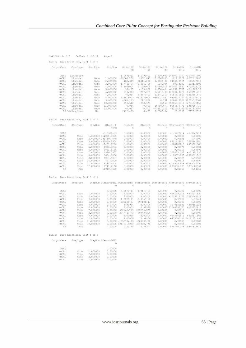
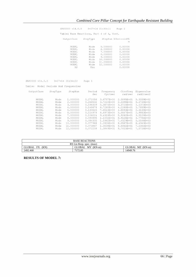
Results Of Model 6:
Combined Core Pillar Concept for Earthquake Resistant Building
www.iosrjournals.org 65 | Page
Combined Core Pillar Concept for Earthquake Resistant Building
www.iosrjournals.org 66 | Page
BASE REACTIONS
RS Lin Resp. spec. (max)
GLOBAL FX (KN) GLOBAL MY (KN-m) GLOBAL MZ (KN-m)
2492.468 7172.85 14949.76
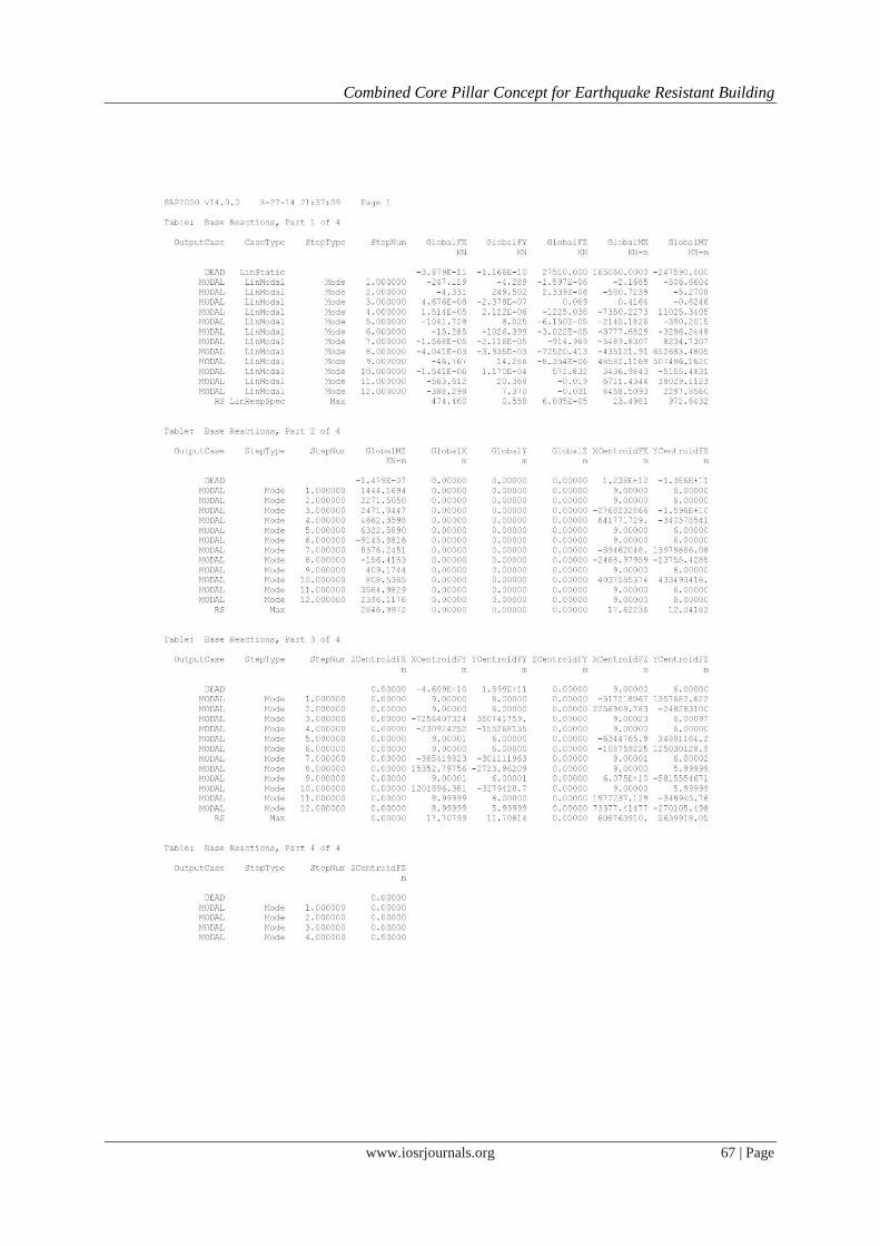
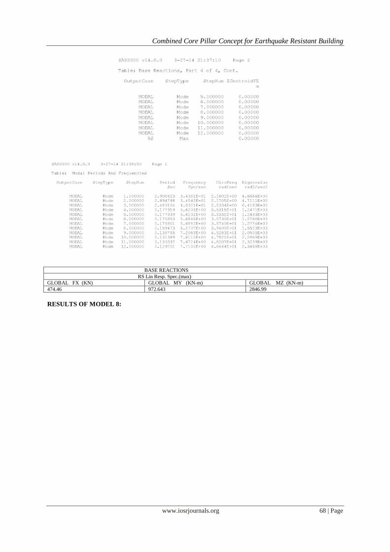
RESULTS OF MODEL 7:
Combined Core Pillar Concept for Earthquake Resistant Building
www.iosrjournals.org 67 | Page
Combined Core Pillar Concept for Earthquake Resistant Building
www.iosrjournals.org 68 | Page
BASE REACTIONS
RS Lin Resp. Spec.(max)
GLOBAL FX (KN) GLOBAL MY (KN-m) GLOBAL MZ (KN-m)
474.46 972.643 2846.99
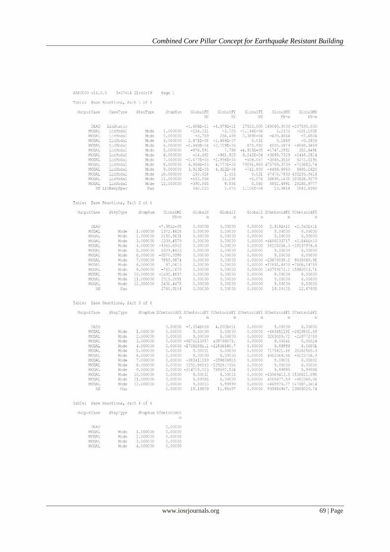
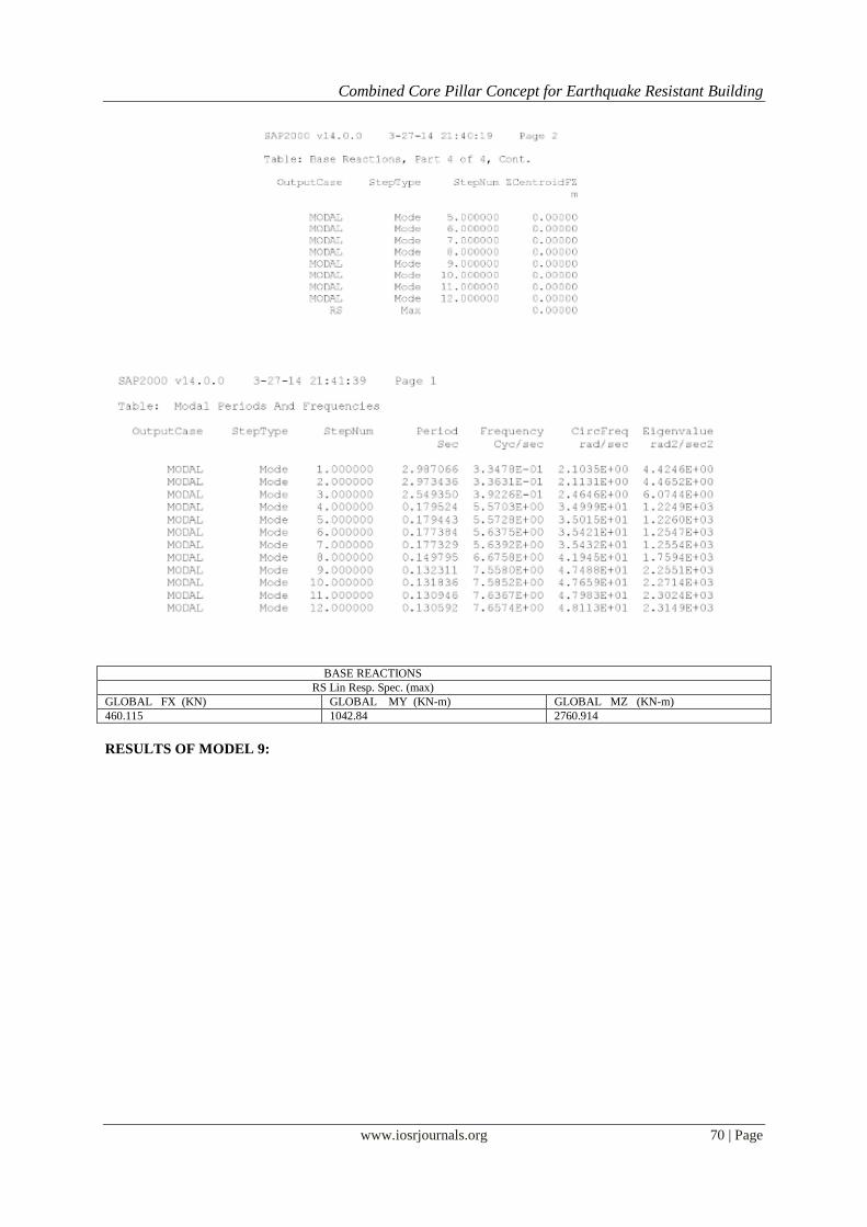
RESULTS OF MODEL 8:
Combined Core Pillar Concept for Earthquake Resistant Building
www.iosrjournals.org 69 | Page
Combined Core Pillar Concept for Earthquake Resistant Building
www.iosrjournals.org 70 | Page
BASE REACTIONS
RS Lin Resp. Spec. (max)
GLOBAL FX (KN) GLOBAL MY (KN-m) GLOBAL MZ (KN-m)
460.115 1042.84 2760.914
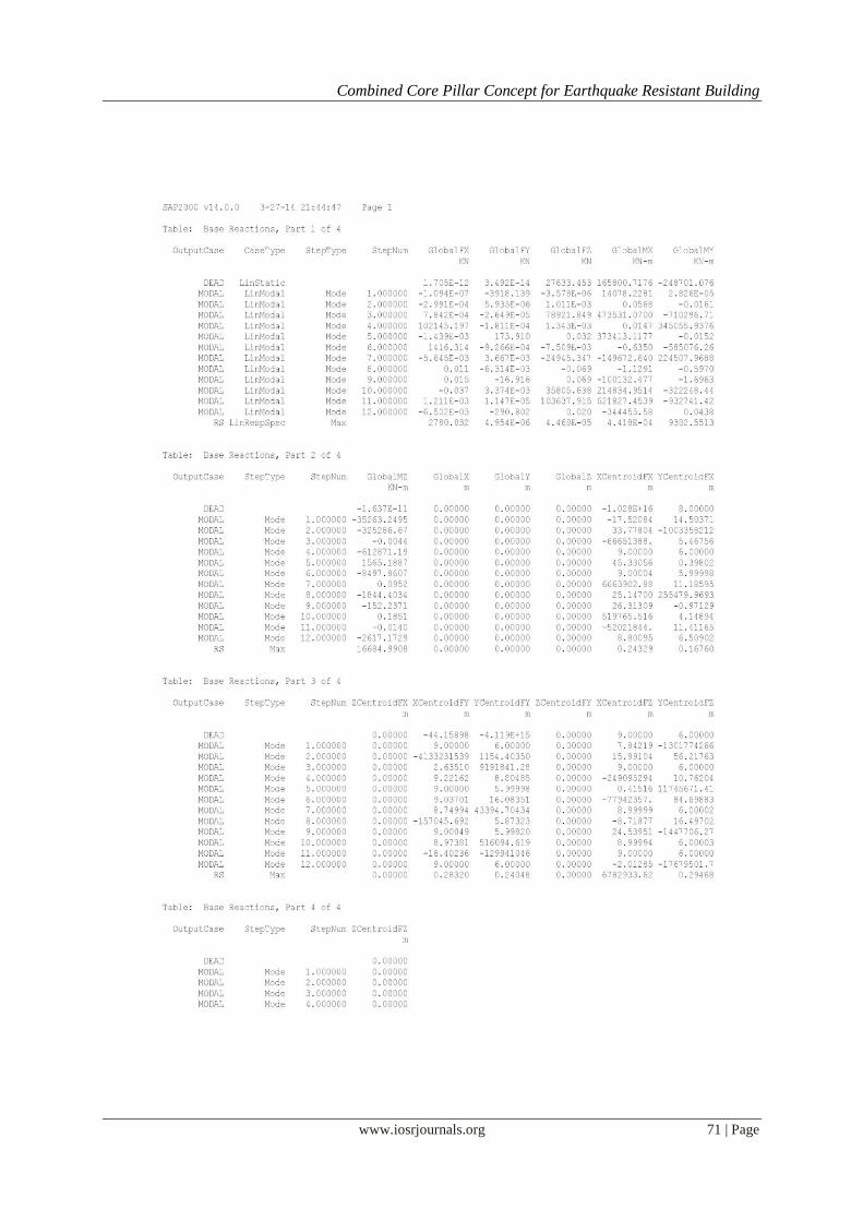
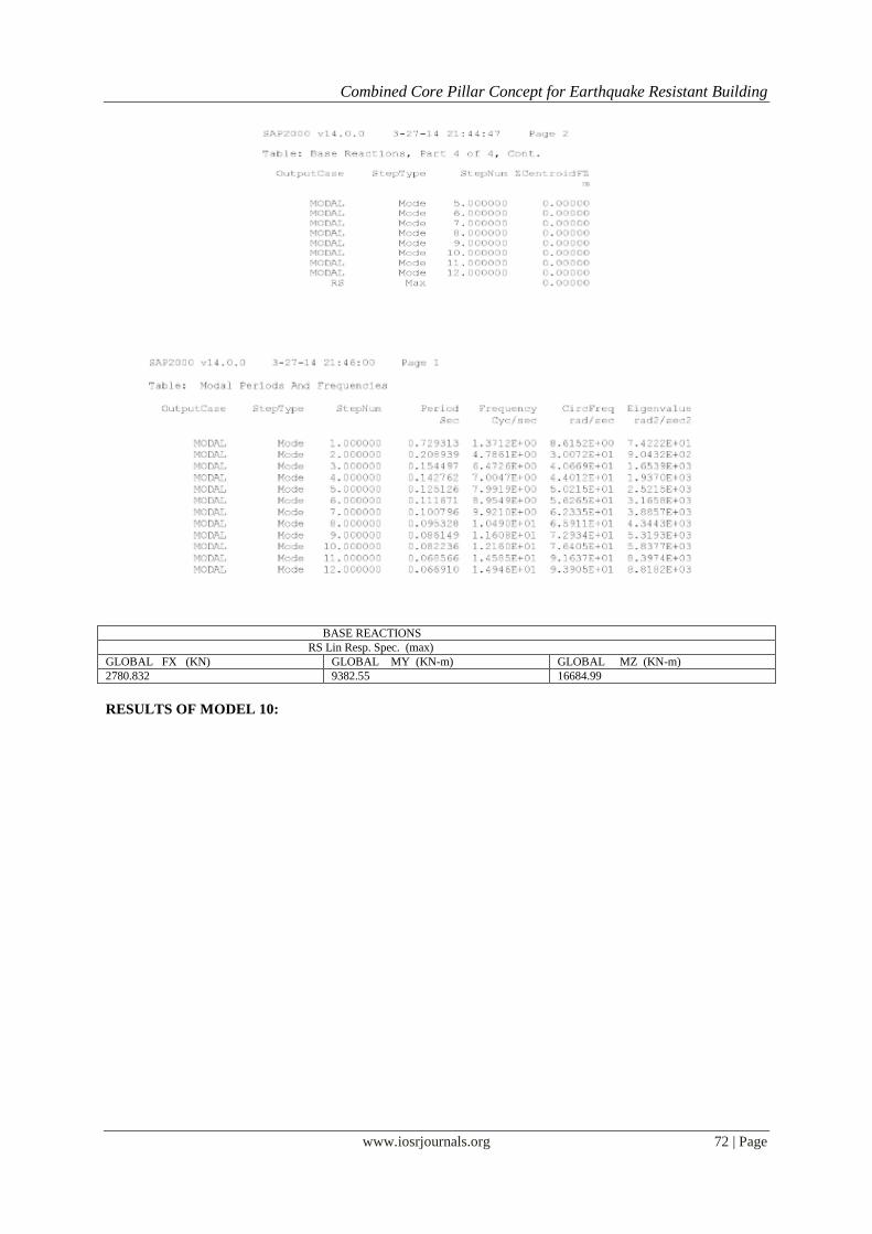
RESULTS OF MODEL 9:
Combined Core Pillar Concept for Earthquake Resistant Building
www.iosrjournals.org 71 | Page
Combined Core Pillar Concept for Earthquake Resistant Building
www.iosrjournals.org 72 | Page
BASE REACTIONS
RS Lin Resp. Spec. (max)
GLOBAL FX (KN) GLOBAL MY (KN-m) GLOBAL MZ (KN-m)
2780.832 9382.55 16684.99
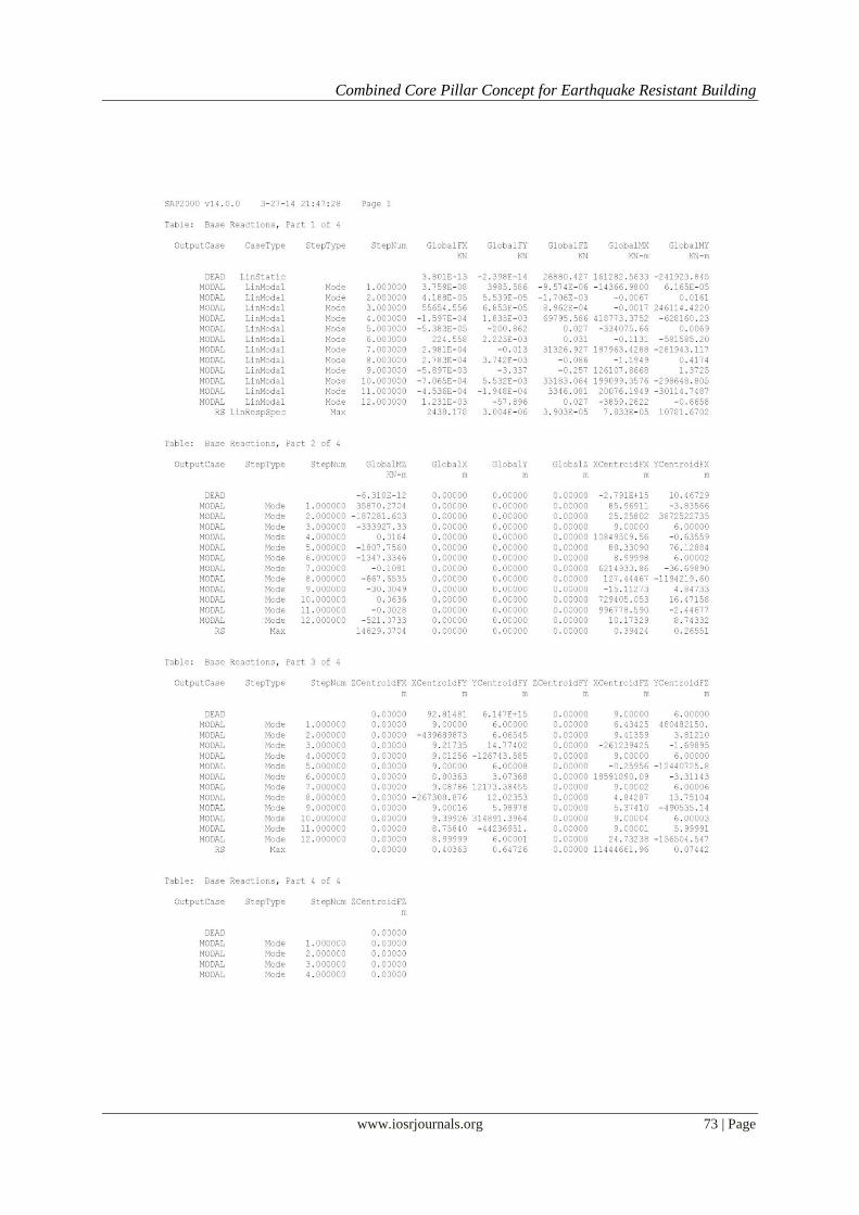
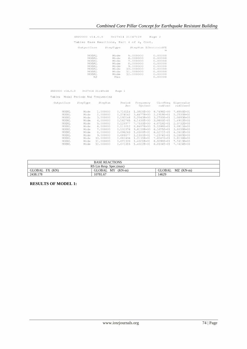
RESULTS OF MODEL 10:
Combined Core Pillar Concept for Earthquake Resistant Building
www.iosrjournals.org 73 | Page
Combined Core Pillar Concept for Earthquake Resistant Building
www.iosrjournals.org 74 | Page
BASE REACTIONS
RS Lin Resp. Spec.(max)
GLOBAL FX (KN) GLOBAL MY (KN-m) GLOBAL MZ (KN-m)
2438.178 10781.67 14629
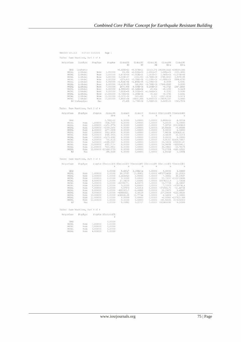
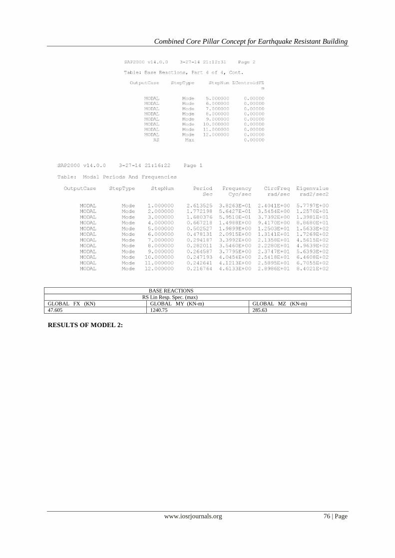
RESULTS OF MODEL 1:
Combined Core Pillar Concept for Earthquake Resistant Building
www.iosrjournals.org 75 | Page
Combined Core Pillar Concept for Earthquake Resistant Building
www.iosrjournals.org 76 | Page
BASE REACTIONS
RS Lin Resp. Spec. (max)
GLOBAL FX (KN) GLOBAL MY (KN-m) GLOBAL MZ (KN-m)
47.605 1240.75 285.63
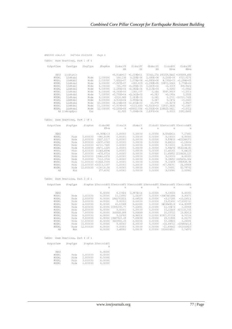
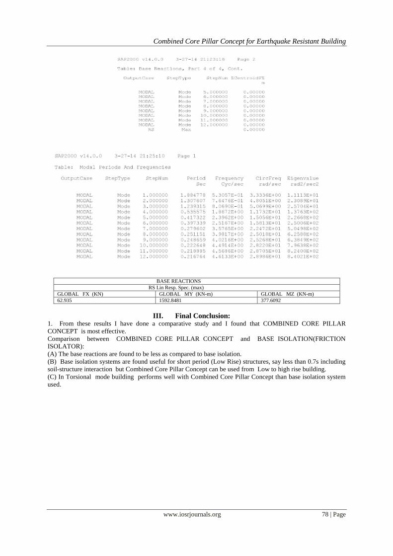
RESULTS OF MODEL 2:
Combined Core Pillar Concept for Earthquake Resistant Building
www.iosrjournals.org 77 | Page
Combined Core Pillar Concept for Earthquake Resistant Building
www.iosrjournals.org 78 | Page
BASE REACTIONS
RS Lin Resp. Spec. (max)
GLOBAL FX (KN) GLOBAL MY (KN-m) GLOBAL MZ (KN-m)
62.935 1592.8481 377.6092
III. Final Conclusion: 1. From these results I have done a comparative study and I found that COMBINED CORE PILLAR
CONCEPT is most effective.
Comparison between COMBINED CORE PILLAR CONCEPT and BASE ISOLATION(FRICTION
ISOLATOR):
(A) The base reactions are found to be less as compared to base isolation.
(B) Base isolation systems are found useful for short period (Low Rise) structures, say less than 0.7s including
soil-structure interaction but Combined Core Pillar Concept can be used from Low to high rise building.
(C) In Torsional mode building performs well with Combined Core Pillar Concept than base isolation system
used.