Embed Size (px)
Citation preview
1
COMBINED HEAT AND POWER (CHP) GENERATION
Directive 2012/27/EU of the European Parliament and of the Council Commission Decision 2008/952/EC
May 2017
The reporting template combined heat and power generation allows for data transmission starting with reference year 2016.
According to DIRECTIVE 2012/27/EU of the European Parliament and of the Council of 25
October 2012 on energy efficiency, amending Directives 2009/125/EC and 2010/30/EU and
repealing Directives 2004/8/EC and 2006/32/EC the deadline for providing data is the 30st of
April the second year after the reference year (T+2).
Please send your reporting template to:
European Commission, Eurostat, Energy Statistics (for Member States of the European Union, EU Candidate Countries and EFTA Countries)
Transmission details are provided below:
The completed reporting template should be transmitted to Eurostat via the Single Entry Point (SEP) following the implementing procedures of eDAMIS (electronic Data files Administration and Management Information System), selecting the electronic data collection ENERGY_CHP_A and indicating the submission year. E-MAIL ADDRESS [email protected]
NOTE For questions regarding the questionnaire, contact Mr Michael Goll e-mail: [email protected] Telephone: + 352 4301 32782

2
Foreword
The purpose of these Reporting Instructions is to help statisticians in EU Member States and
in other countries to fill the CHP reporting template correctly. It is written in a way as to make
also non-CHP experts understand the basic ideas and concepts behind the data collection.
Therefore, certain aspects are described in a simplified manner and are probably from a
technical perspective not always 100% correct. This is done to keep these instructions
manageable.
3
Contents
Foreword .................................................................................................................................... 2
1. Introduction ..................................................................................................................... 4 1.1. Purpose of the data collection ............................................................................... 5 1.2. Different CHP technologies ................................................................................... 6
1.2.1. Mode of production .................................................................................................. 6 1.2.2. Type of technologies ................................................................................................ 7
1.2.3. 'Normal' setup of a CHP installation (Commission Decision 2008/952/EC) .......... 7 2. Definitions ....................................................................................................................... 8
Heat ........................................................................................................................................ 8
Electricity ............................................................................................................................... 9 Fuel ......................................................................................................................................... 9 Efficiencies ........................................................................................................................... 10 Power-to-heat ratio (= C) ..................................................................................................... 11
Capacities ............................................................................................................................. 12 Other definitions ................................................................................................................... 14
3. Assumptions .................................................................................................................. 15 3.1. Overall efficiencies and full cogeneration mode ............................................... 15
3.2. What should the operator of a CHP unit know? .............................................. 15 3.3. Which parameters are measured? ..................................................................... 16
4. The CHP reporting template ......................................................................................... 17 5. The whole data treatment process can be divided into five major steps: ...................... 18
Flowchart for the CHP reporting template ........................................................................... 19 Step 1: Check system boundaries and calculate the overall efficiency of the CHP unit: .... 20 Step 2: Distinguish ECHP from Enon-CHP ................................................................................ 21
Step 3: Determination of fuel consumption for non-CHP-electricity .................................. 21 Step 4: Calculation of Primary Energy Savings (= PES) ..................................................... 22
Step 5: Aggregation of fuels by fuel type for the generation of CHP products ................... 24 6. References ..................................................................................................................... 26 Annex 1: Explanations regarding dual purpose boilers and reduction heat ............................. 27 Annex 2: Calculation of reference values for separate production of electricity and heat ...... 28
Annex 3: Practical examples .................................................................................................... 29
Table 1: different CHP technologies .......................................................................................... 6 Table 2: default power-to-heat values (Cdefault) ........................................................................ 12 Table 3: indicative default values for β if it is not known or cannot be calculated .................. 14 Table 4: For data reporting according to Directive 2012/27/EU excel tables (reporting
templates) are provided. ............................................................................................. 17
4
1. Introduction
Energy included in fuels is converted into electricity in conventional thermal power stations
with a relatively low efficiency. The amount of generated electrical energy is typically 30 – 40
% of the energy content of the fuel consumed, and even in the most modern power plants it
is 'only' around 60%. The rest of the thermal energy is emitted into the environment.
The principle of combined heat and power production (CHP) is to use the remaining heat
from the power generation for example for heating of buildings or in industrial processes as
process heat.
By doing so primary energy can be saved by this simultaneous production of heat and
electricity. This means that less fuel is used than in separated generation processes
(electricity only, heat only). CHP units have the potential to work with high total efficiency and
the amount of losses can be reduced even down to 10 – 20 % of the used fuel.
CHP technologies are typically used for district heating networks or to supply industries with
process heat, but CHP is also used in agriculture, the residential sector and the tertiary
sector.
However, the dissemination of the generated heat is a challenge due to the distribution
losses. But also other obstacles for the heat distribution exist.
As a consequence of these losses when transporting heat in pipes or networks, CHP
installations should be established as near as possible to the consumers of the heat.
Therefore, big electrical power plants (e.g. nuclear power plants, power plants using lignite)
are very often not equipped with a CHP technology due to their distance to the consumers of
the heat. However, some exceptions exist.
Power plants can consist of several units, which may or may not be CHP units. It is therefore
important to identify the CHP unit and to respect the CHP system boundaries (Commission
Decision 2008/952/EC).
Different CHP technologies have been developed. They can be split into two major groups:
Flexible units, which can adapt to the heat demand (adjustable power-to-heat ratio).
These are installations using steam to run a turbine. At certain locations in the turbine
(some) steam is extracted from the turbine and used to provide heat. The extracted
steam can of course not be used for electricity generation. This leads to a loss of
(potential) electricity generation but to the generation of useful heat within the same
process. These technologies can be operated in full cogeneration mode (maximum
heat generation) but also in full condensing mode (no useful heat generation at all but
maximum electricity generation). The power-to-heat ratio varies along these
extremes. The way these installations are operated depends on the demand for heat.
CHP units which cannot adjust to the heat demand. The heat production is constant.
If there is no heat demand, they simply release the generated heat to the
environment.
District heating plants produce heat as a priority product. Nowadays many of them do this
using one of the existing CHP technologies, but pure heat plants are still very common for
district heating systems. However, CHP equipped district heating plants are often also
5
equipped with heat only boilers, which might be used instead of the CHP unit e.g. in summer
time when there is little heat demand or in winter when the heat demand cannot be satisfied
by the CHP unit alone.
1.1. Purpose of the data collection
The purpose of the CHP statistics is to collect data in a harmonised manner on this specific
technology for policy makers allowing them to understand easily how this field develops. The
collected data are not collected to build up CHP quality schemes and will also not be used to
see which operator can claim subsidies for its CHP products.
The method for collecting CHP statistics must be able to cope with all the variable technical
and operational features of CHP production in order to separate the CHP generation from the
total production in a consistent and accurate manner.
Three general principles are to be followed:
a) All useful heat generated in CHP units regardless whether it is used in industry,
district heating etc. and whether it is sold or not is to be reported. This is different
from the reporting of the Annual Electricity and Heat Questionnaire, where only heat
sold has to be reported.
b) As many parameters as possible should be measured. If this is not possible, some
parameters have to be calculated following the descriptions below.
c) Keep the reporting template as simple as possible. The practical data collection on
the CHP units involves sending reporting templates to power plants requesting
capacity and production data. The information asked for has to be clear and readily
available at the plants, since the plant operators may not have enough resources to
find out all the data requested in complicated forms.
For most of the plants it is not a difficult task to fill in the reporting template, but for
units producing both CHP-electricity and non-CHP-electricity the reporting
templates to be completed are not necessarily straightforward. The accurate
calculation of the real CHP-electricity generation in these units would require day-to-
day data on generation and on the thermodynamics of the system, for example
temperature and mass flow measurements. The process computers are not
necessarily designed for producing and storing data for statistical purposes, and often
the distinction between the CHP production and non-CHP production has to be done
by some other method.
The probability of not receiving data or obtaining data of poor quality increases if the
method is too complicated. Therefore, the method has to be simple enough and
unequivocal to avoid possible misinterpretations. The calculations on the real CHP
production must be possible by knowing the annual production, electricity and heat,
and fuel input.
6
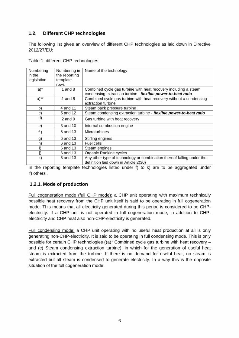
1.2. Different CHP technologies
The following list gives an overview of different CHP technologies as laid down in Directive
2012/27/EU:
Table 1: different CHP technologies
Numbering in the legislation
Numbering in the reporting template rows
Name of the technology
a)* 1 and 8 Combined cycle gas turbine with heat recovery including a steam condensing extraction turbine– flexible power-to-heat ratio
a)** 1 and 8 Combined cycle gas turbine with heat recovery without a condensing extraction turbine
b) 4 and 11 Steam back pressure turbine
c) 5 and 12 Steam condensing extraction turbine - flexible power-to-heat ratio
d) 2 and 9 Gas turbine with heat recovery
e) 3 and 10 Internal combustion engine
f ) 6 and 13 Microturbines
g) 6 and 13 Stirling engines
h) 6 and 13 Fuel cells
i) 6 and 13 Steam engines
j) 6 and 13 Organic Rankine cycles
k) 6 and 13 Any other type of technology or combination thereof falling under the definition laid down in Article 2(30)
In the reporting template technologies listed under f) to k) are to be aggregated under
'f) others'.
1.2.1. Mode of production
Full cogeneration mode (full CHP mode): a CHP unit operating with maximum technically
possible heat recovery from the CHP unit itself is said to be operating in full cogeneration
mode. This means that all electricity generated during this period is considered to be CHP-
electricity. If a CHP unit is not operated in full cogeneration mode, in addition to CHP-
electricity and CHP heat also non-CHP-electricity is generated.
Full condensing mode: a CHP unit operating with no useful heat production at all is only
generating non-CHP-electricity. It is said to be operating in full condensing mode. This is only
possible for certain CHP technologies ((a)* Combined cycle gas turbine with heat recovery –
and (c) Steam condensing extraction turbine), in which for the generation of useful heat
steam is extracted from the turbine. If there is no demand for useful heat, no steam is
extracted but all steam is condensed to generate electricity. In a way this is the opposite
situation of the full cogeneration mode.
7
1.2.2. Type of technologies
Technologies mentioned in table 1 under a)* and c) work on the basis of steam
condensation. By extracting more or less steam from the turbine they can adjust their heat
and electricity generation. They can be operated in full CHP mode (maximum useful heat
production) or in the other extreme, in full condensing mode which means maximum
electricity generation and no useful heat production.
Therefore, they can adapt to the useful heat demand. Full CHP mode means a maximum
production of CHP products (CHP-electricity and useful heat), while the condensing mode
means only non-CHP-electricity generation.
These technologies represent a compromise:
In full CHP mode they produce a maximum of useful heat (the limitation is often the capacity
of the heat exchanger) and less electricity (but CHP-electricity) than they could generate in
full condensing mode. The electricity generated in full condensing mode is only non-CHP-
electricity. In other words in full CHP mode the electricity generation is sacrificed for the sake
of useful heat production.
Technologies mentioned in table 1 under a)**, b), d), e), f), g), h), i), j) and k) cannot adjust
their heat production when generating electricity. If heat is needed (= useful), it is collected
and used e.g. for heating of houses. If no heat is needed, the heat accumulated during
electricity generation is just released to the environment.
1.2.3. 'Normal' setup of a CHP installation (Commission Decision 2008/952/EC)
Elements needed to run a steam driven CHP installation (Table 1, a) to d)) are, for example:
- a boiler to produce steam
- a turbine using the steam to produce kinetic energy
- a generator to convert the kinetic energy into electrical energy
- a heat exchanger to provide the useful heat to a district heating network
- in industrial use exhaust gases can be used directly
Often there are additional boilers installed as back-up or as supporting elements (e.g. in
winter when there is a high demand for heat). These additional boilers don’t belong to the
CHP units.
In special cases the boiler to produce the steam for the CHP unit could be used for dual
purpose and produce steam for the CHP unit and e.g. for industrial customers (dual purpose
boiler). For more details please see Annex I.
8
2. Definitions
Heat
a) Useful heat (HCHP)(= CHP heat): this is the central product of any CHP unit and it is
defined as 'heat from a CHP scheme delivered to satisfy an economically justifiable
demand for heat or cooling. Heat that is used for process or space heating and/or
delivered for subsequent cooling purposes. Heat delivered to district heating/cooling
networks; exhaust gases from a cogeneration process that are used for direct heating
and drying purposes'.
The demand is very important in this case because the electricity generated at the
same time as the heat can only be qualified as being CHP-electricity if the heat is
used in a meaningful way. If, because there is no demand for the heat, the heat is just
released to the environment, this heat is non-CHP heat and consequently the
electricity generated at the same time cannot be labelled as being CHP-electricity,
because it is non-CHP-electricity.
Useful heat is measured normally at the heat exchanger to the network / distribution infrastructure. This quantity is net.
Examples for heat which is not useful: heat rejected to the environment, lost from
chimneys or exhausts; heat rejected in equipment (condensers, heat dump radiators).
More in Commission Decision 2008/952/EC, annex, Part I, point 5.7.
HCHP is to be reported in column F of tables EU-1B and EU1C
b) Supplementary heat (Hsuppl) is heat which is produced outside of the cogeneration
system boundaries or the CHP unit (e.g. heat produced in a conventional or in an
auxiliary boiler). This supplementary heat is either measured or calculated by
measuring the fuel used multiplied with the reference (heat) efficiencies for the fuel
used (see Commission Delegated Regulation (EU) 2015/2402).
Heat production in auxiliary boilers might happen at times when there is only little
heat demand from district heating plants i.e. in summer time, when there is only
demand for hot tap water but not for space heating purposes. Also in winter when the
heat demand cannot be satisfied by the CHP unit alone heat is produced in auxiliary
(heat only) boilers. Other reasons for alternative heat production in heat only boilers
might be: during maintenance of the CHP installation, when the CHP installation
breaks down (back-up) or when electricity generation is not profitable.
c) Total heat (Htotal) is the heat produced by the boiler of the installation of which the
CHP unit might be only a part.
Htotal = HCHP + Hsuppl [equation 1]
d) Reduction heat (Hreduct) is heat produced in dual purpose boilers also supplying CHP
units with heat. For more details please see Annex I.
9
Electricity
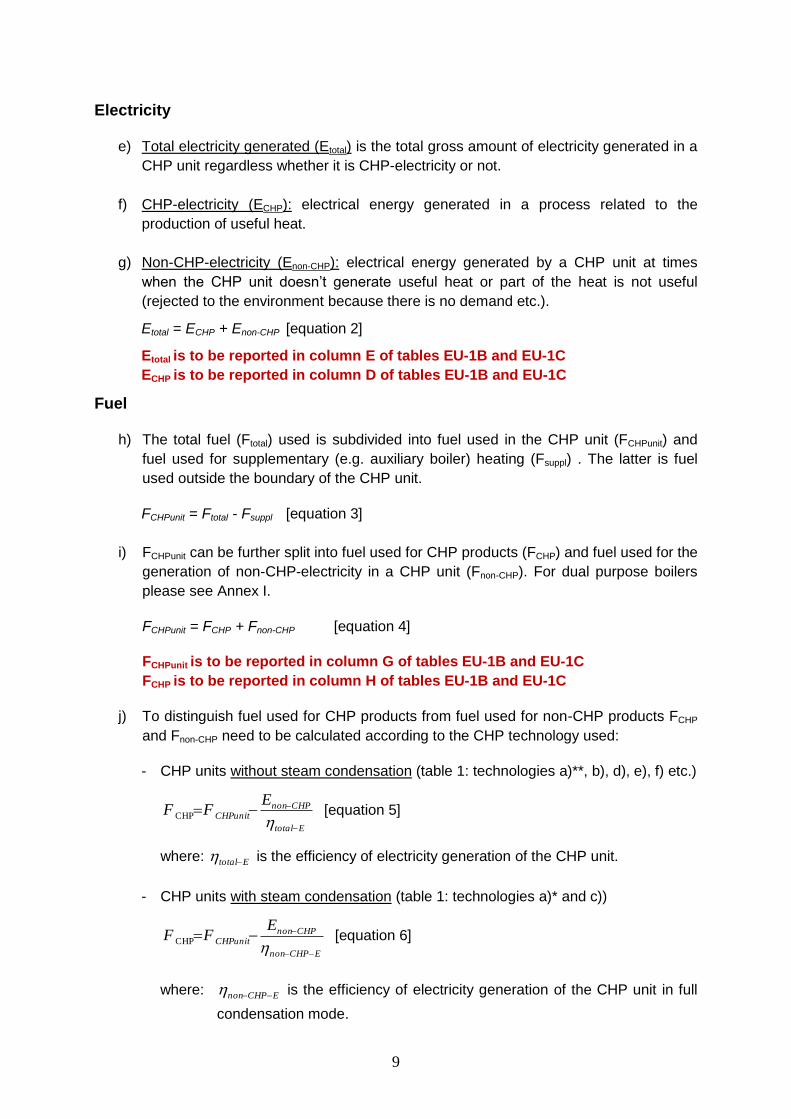
e) Total electricity generated (Etotal) is the total gross amount of electricity generated in a
CHP unit regardless whether it is CHP-electricity or not.
f) CHP-electricity (ECHP): electrical energy generated in a process related to the
production of useful heat.
g) Non-CHP-electricity (Enon-CHP): electrical energy generated by a CHP unit at times
when the CHP unit doesn’t generate useful heat or part of the heat is not useful
(rejected to the environment because there is no demand etc.).
Etotal = ECHP + Enon-CHP [equation 2]
Etotal is to be reported in column E of tables EU-1B and EU-1C
ECHP is to be reported in column D of tables EU-1B and EU-1C
Fuel
h) The total fuel (Ftotal) used is subdivided into fuel used in the CHP unit (FCHPunit) and
fuel used for supplementary (e.g. auxiliary boiler) heating (Fsuppl) . The latter is fuel
used outside the boundary of the CHP unit.
FCHPunit = Ftotal - Fsuppl [equation 3]
i) FCHPunit can be further split into fuel used for CHP products (FCHP) and fuel used for the
generation of non-CHP-electricity in a CHP unit (Fnon-CHP). For dual purpose boilers
please see Annex I.
FCHPunit = FCHP + Fnon-CHP [equation 4]
FCHPunit is to be reported in column G of tables EU-1B and EU-1C
FCHP is to be reported in column H of tables EU-1B and EU-1C
j) To distinguish fuel used for CHP products from fuel used for non-CHP products FCHP
and Fnon-CHP need to be calculated according to the CHP technology used:
- CHP units without steam condensation (table 1: technologies a)**, b), d), e), f) etc.)
Etotal
CHPnonCHPunit
EFF
CHP [equation 5]
where: Etotal is the efficiency of electricity generation of the CHP unit.
- CHP units with steam condensation (table 1: technologies a)* and c))
ECHPnon
CHPnonCHPunit
EFF
CHP [equation 6]
where: ECHPnon is the efficiency of electricity generation of the CHP unit in full
condensation mode.
10
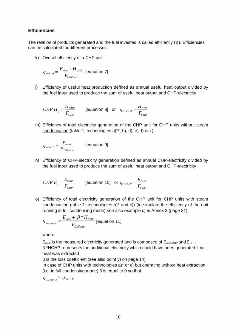
Efficiencies
The relation of products generated and the fuel invested is called efficiency (). Efficiencies
can be calculated for different processes
k) Overall efficiency of a CHP unit
CHPunit
CHPtotaloverall
F
HE [equation 7]
l) Efficiency of useful heat production defined as annual useful heat output divided by
the fuel input used to produce the sum of useful heat output and CHP-electricity
CHP
CHP
F
HHCHP [equation 8] or
CHP
CHPHCHP
F
H
m) Efficiency of total electricity generation of the CHP unit for CHP units without steam
condensation (table 1: technologies a)**, b), d), e), f) etc.)
CHPunit
totalEtotal
F
E [equation 9]
n) Efficiency of CHP-electricity generation defined as annual CHP-electricity divided by
the fuel input used to produce the sum of useful heat output and CHP-electricity
CHP
CHP
F
EECHP [equation 10] or
CHP
CHPECHP
F
E
o) Efficiency of total electricity generation of the CHP unit for CHP units with steam
condensation (table 1: technologies a)* and c)) (to simulate the efficiency of the unit
running in full condensing mode) see also example c) in Annex 3 (page 31).
CHPunit
CHPtotal
F
HEECHPnon
*
[equation 11]
where:
Etotal is the measured electricity generated and is composed of Enon-CHP and ECHP
β *HCHP represents the additional electricity which could have been generated if no
heat was extracted
β is the loss coefficient (see also point y) on page 14)
In case of CHP units with technologies a)* or c) but operating without heat extraction
(i.e. in full condensing mode) β is equal to 0 so that
ECHPnon = Etotal
11
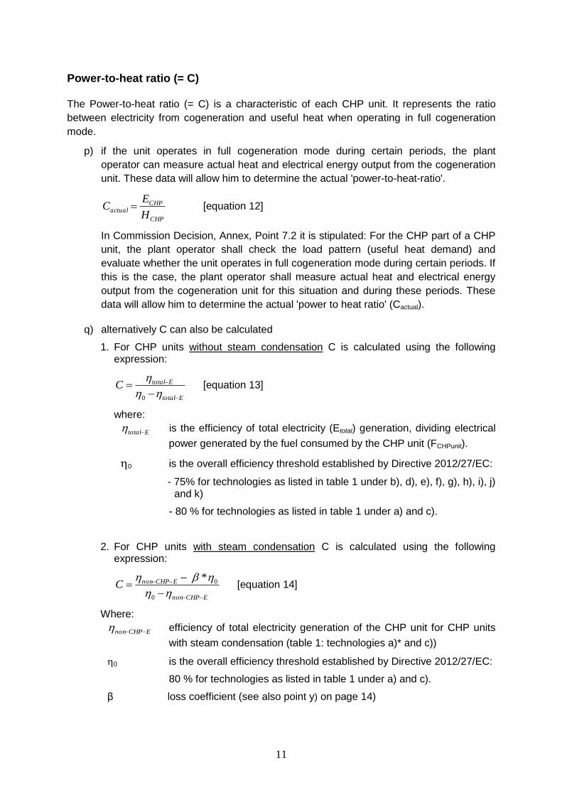
Power-to-heat ratio (= C)
The Power-to-heat ratio (= C) is a characteristic of each CHP unit. It represents the ratio
between electricity from cogeneration and useful heat when operating in full cogeneration
mode.
p) if the unit operates in full cogeneration mode during certain periods, the plant
operator can measure actual heat and electrical energy output from the cogeneration
unit. These data will allow him to determine the actual 'power-to-heat-ratio'.
CHP
CHPactual
H
EC [equation 12]
In Commission Decision, Annex, Point 7.2 it is stipulated: For the CHP part of a CHP
unit, the plant operator shall check the load pattern (useful heat demand) and
evaluate whether the unit operates in full cogeneration mode during certain periods. If
this is the case, the plant operator shall measure actual heat and electrical energy
output from the cogeneration unit for this situation and during these periods. These
data will allow him to determine the actual 'power to heat ratio' (Cactual).
q) alternatively C can also be calculated
1. For CHP units without steam condensation C is calculated using the following expression:
Etotal
EtotalC
0
[equation 13]
where:
Etotal is the efficiency of total electricity (Etotal) generation, dividing electrical
power generated by the fuel consumed by the CHP unit (FCHPunit).
0 is the overall efficiency threshold established by Directive 2012/27/EC:
- 75% for technologies as listed in table 1 under b), d), e), f), g), h), i), j) and k)
- 80 % for technologies as listed in table 1 under a) and c).
2. For CHP units with steam condensation C is calculated using the following expression:
ECHPnon
ECHPnonC
0
0* [equation 14]
Where:
ECHPnon efficiency of total electricity generation of the CHP unit for CHP units
with steam condensation (table 1: technologies a)* and c))
0 is the overall efficiency threshold established by Directive 2012/27/EC:
80 % for technologies as listed in table 1 under a) and c).
β loss coefficient (see also point y) on page 14)
12
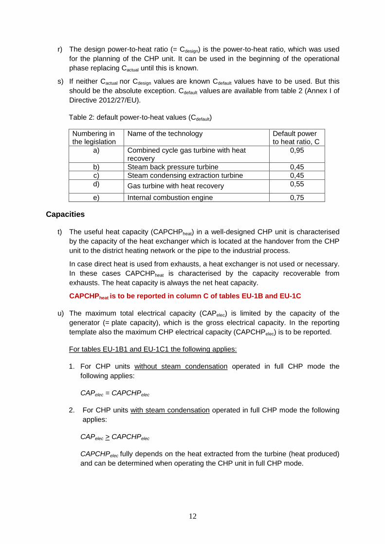
r) The design power-to-heat ratio (= Cdesign) is the power-to-heat ratio, which was used
for the planning of the CHP unit. It can be used in the beginning of the operational
phase replacing Cactual until this is known.
s) If neither Cactual nor Cdesign values are known Cdefault values have to be used. But this
should be the absolute exception. Cdefault values are available from table 2 (Annex I of
Directive 2012/27/EU).
Table 2: default power-to-heat values (Cdefault)
Numbering in the legislation
Name of the technology Default power to heat ratio, C
a) Combined cycle gas turbine with heat recovery
0,95
b) Steam back pressure turbine 0,45
c) Steam condensing extraction turbine 0,45
d) Gas turbine with heat recovery 0,55
e) Internal combustion engine 0,75
Capacities
t) The useful heat capacity (CAPCHPheat) in a well-designed CHP unit is characterised
by the capacity of the heat exchanger which is located at the handover from the CHP
unit to the district heating network or the pipe to the industrial process.
In case direct heat is used from exhausts, a heat exchanger is not used or necessary.
In these cases CAPCHPheat is characterised by the capacity recoverable from
exhausts. The heat capacity is always the net heat capacity.
CAPCHPheat is to be reported in column C of tables EU-1B and EU-1C
u) The maximum total electrical capacity (CAPelec) is limited by the capacity of the
generator (= plate capacity), which is the gross electrical capacity. In the reporting
template also the maximum CHP electrical capacity (CAPCHPelec) is to be reported.
For tables EU-1B1 and EU-1C1 the following applies:
1. For CHP units without steam condensation operated in full CHP mode the
following applies:
CAPelec = CAPCHPelec
2. For CHP units with steam condensation operated in full CHP mode the following
applies:
CAPelec > CAPCHPelec
CAPCHPelec fully depends on the heat extracted from the turbine (heat produced)
and can be determined when operating the CHP unit in full CHP mode.
13
CAPCHPelec is calculated as follows:
CAPCHPelec = CAPelec – βdesign x CAPCHPheat [equation 15]
Alternatively, for CHP units with steam condensation CAPCHPelec is to be
determined under test conditions (full CHP mode) by the operator of the CHP unit.
CAPCHPelec is to be reported in column A of tables EU-1B and EU-1C
CAPelec is to be reported in column B of tables EU-1B and EU-1C
For tables EU-1B2 and EU-1C2 the following applies:
1. For all CHP units not operated in full CHP mode the following applies:
The CHP electrical capacity (CAPCHPelec) might be calculated using the formula:
CAPCHPelec = CAPCHPheat * C [equation 16]
In the extreme case (full non-CHP mode):
CAPelec = CAPnon-CHPelec
CAPCHPelec is to be reported in column A of tables EU-1B and EU-1C
v) For CHP units, without generation of CHP products (CHP electricity and useful heat)
in the reference year, CAPCHPelec, CAPelec and CAPCHPheat are to be reported in
Table EU-1D (underneath table EU-1C2) in columns A, B and C respectively.
These CHP units could also be called 'dormant CHP units'.
14
Other definitions
w) CHP products are sometimes also called cogeneration products. These are those
products generated in cogeneration mode of the CHP units: useful heat (= CHP heat) and CHP-electricity.
x) In contrast to this are the non-CHP products, which are also generated in a CHP unit when it is not operated in cogeneration mode. The non-CHP product generated is mainly non-CHP-electricity.
y) Loss coefficient β. This value is only applicable for CHP units with steam
condensation in cogeneration mode. It reflects the effect of steam extraction on the
electricity generation. It is expressed as the loss of electricity generation per unit of
extracted heat.
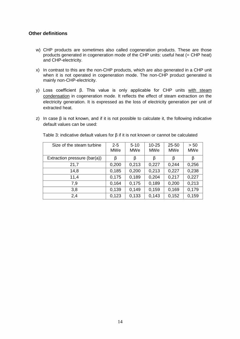
z) In case β is not known, and if it is not possible to calculate it, the following indicative
default values can be used:
Table 3: indicative default values for β if it is not known or cannot be calculated
Size of the steam turbine 2-5 MWe
5-10 MWe
10-25 MWe
25-50 MWe
> 50 MWe
Extraction pressure (bar(a)) β β β β β
21,7 0,200 0,213 0,227 0,244 0,256
14,8 0,185 0,200 0,213 0,227 0,238
11,4 0,175 0,189 0,204 0,217 0,227
7,9 0,164 0,175 0,189 0,200 0,213
3,8 0,139 0,149 0,159 0,169 0,179
2,4 0,123 0,133 0,143 0,152 0,159
15
3. Assumptions
3.1. Overall efficiencies and full cogeneration mode
After some modifications of the proposed Protermo statistical methodology the following was
agreed:
a) If a CHP unit using a technology as specified in table 1 under b), d), e), (f), (g), (h), (i),
(j) or (k) reaches a minimum overall efficiency of equal or more than 75% it can be
assumed that it was operated in full cogeneration mode over the observed /
measured time period. Therefore, it can be assumed that all electricity measured at
the generator clamps is in fact CHP-electricity.
b) If a CHP unit using a technology as specified in table 1 under a) or c) reaches a
minimum overall efficiency of equal or more than 80% it can be assumed that it was
operated in full cogeneration mode over the time period. Therefore, it can be
assumed that all electricity measured at the generator clamps is in fact CHP-
electricity.
c) Should the overall efficiency of the CHP unit be below these minimum limits, it can be
assumed that the CHP unit was not operated in full cogeneration mode during the
observation period. Therefore, it is assumed that apart from CHP-electricity also non-
CHP-electricity was generated.
3.2. What should the operator of a CHP unit know?
d) Commission Decision 2008/952/EC illustrates in its figures which installations belong
to the CHP unit and which don’t (auxiliary boilers, etc.)?
e) What is the electrical capacity of the CHP unit (CAPelec)?
f) What is the capacity (thermal) of the heat exchanger (CAPCHPheat)?
g) How much fuel was used by the installation of which the CHP unit is an integral part
in the last year (Fchp unit)?
h) How much electricity was generated by the CHP unit last year (Etotal)?
i) How much useful heat was generated by the CHP unit last year (HCHP)?
j) What is the actual power-to-heat value (Cactual) of the CHP unit?
k) How much electricity was injected to the grid (needed to calculate PES)?
l) What was the supply voltage (= connection voltage level) (needed to calculate PES)?
m) What is the age of the CHP installation (needed to calculate PES)?
n) If the CHP installation uses waste steam, the fuel used to generate the steam needs
to be known (needed to calculate PES).
o) Way of heat use (Hot water, steam or direct use of exhaust gases).

16
3.3. Which parameters are measured?
p) The fuel used by the CHP unit (FCHPunit) is normally metered at the entry of the burner
/ boiler of the CHP unit. If only the total fuel consumed by the plant (Ftotal) of which the
CHP unit is an integral part is known, this can be calculated if the efficiency of the
auxiliary boiler (boiler) and the heat produced (Hsuppl)is known.
q) Total gross electricity generated (measured at the clamps of the generator).
r) Total useful heat (HCHP) produced (measured at the heat exchanger to the network /
pipe).
17
4. The CHP reporting template
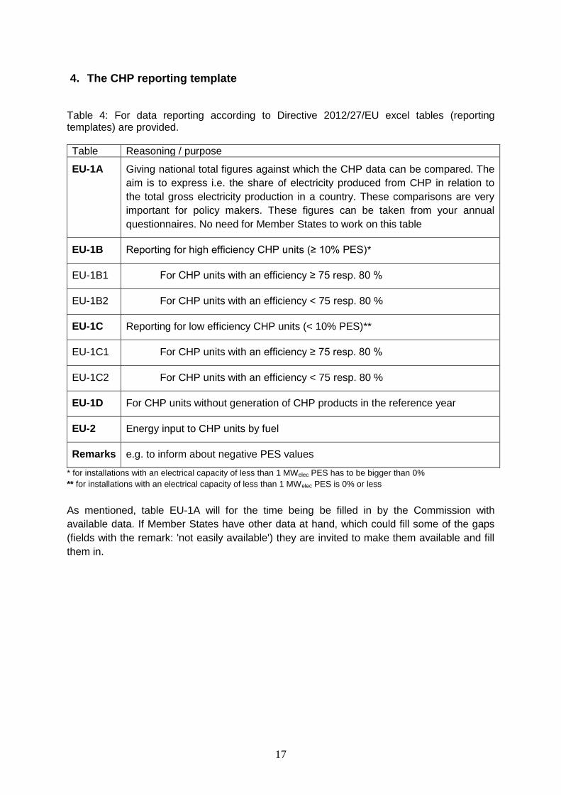
Table 4: For data reporting according to Directive 2012/27/EU excel tables (reporting templates) are provided.
Table Reasoning / purpose
EU-1A Giving national total figures against which the CHP data can be compared. The
aim is to express i.e. the share of electricity produced from CHP in relation to
the total gross electricity production in a country. These comparisons are very
important for policy makers. These figures can be taken from your annual
questionnaires. No need for Member States to work on this table
EU-1B Reporting for high efficiency CHP units (≥ 10% PES)*
EU-1B1 For CHP units with an efficiency ≥ 75 resp. 80 %
EU-1B2 For CHP units with an efficiency < 75 resp. 80 %
EU-1C Reporting for low efficiency CHP units (< 10% PES)**
EU-1C1 For CHP units with an efficiency ≥ 75 resp. 80 %
EU-1C2 For CHP units with an efficiency < 75 resp. 80 %
EU-1D For CHP units without generation of CHP products in the reference year
EU-2 Energy input to CHP units by fuel
Remarks e.g. to inform about negative PES values
* for installations with an electrical capacity of less than 1 MWelec PES has to be bigger than 0%
** for installations with an electrical capacity of less than 1 MWelec PES is 0% or less
As mentioned, table EU-1A will for the time being be filled in by the Commission with
available data. If Member States have other data at hand, which could fill some of the gaps
(fields with the remark: 'not easily available') they are invited to make them available and fill
them in.
18
5. The whole data treatment process can be divided into five major steps:
In the following chapter information is given to fill in table EU-1B, EU-1C and EU-2.
Step 1 Checking carefully the system boundaries of the CHP unit and then calculating the
overall efficiency. If a given CHP unit reaches the minimum threshold of 75 or 80%
efficiency, the data of the CHP unit have to be reported using either table EU-1B1 or
EU-1C1, i.e. not much more needs to be done.
Step 2 If data on useful heat produced by the CHP unit are provided, CHP-electricity
produced can be calculated if needed (for tables EU-1B2 and EU-1C2).
Step 3 For CHP units reported in tables EU-1B2 and EU-1C2 the fuel used for the generation
of CHP products has to be distinguished from the total fuel input (for CHP and non-
CHP products).
Step 4 The percentage of 'Primary Energy Savings' has to be calculated. Based on this it is
decided whether a CHP unit belongs to table EU-1B or EU-1C. Please report the
capacities (electrical and thermal) of CHP units in which no CHP products have been
produced during the reference year in table EU-1D.
Step 5 The fuel used as input for the generation of CHP products should be aggregated by
specific fuel/by fuel group used in table EU-2.
19
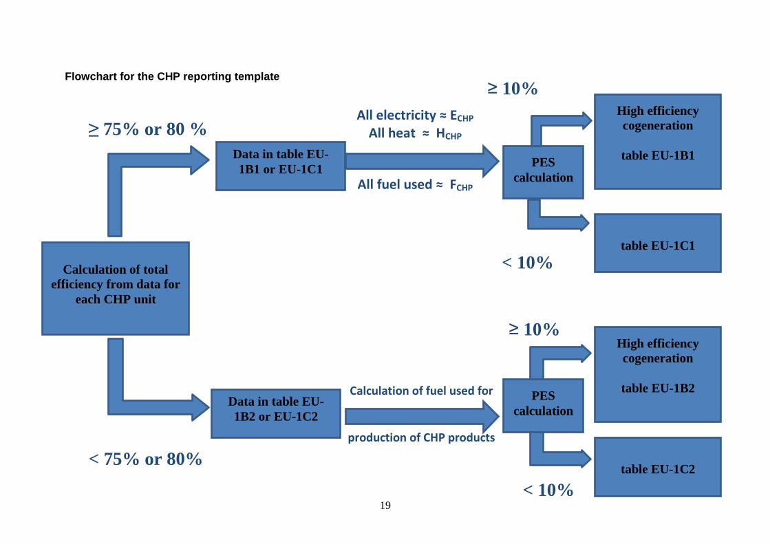
Flowchart for the CHP reporting template
Calculation of fuel used for
production of CHP products
All electricity ≈ ECHP
All heat ≈ HCHP
All fuel used ≈ FCHP
Calculation of total
efficiency from data for
each CHP unit
Data in table EU-
1B1 or EU-1C1
Data in table EU-
1B2 or EU-1C2
≥ 75% or 80 %
80%80%
< 75% or 80%
PES
calculation
PES
calculation
≥ 10%
< 10%
High efficiency
cogeneration
table EU-1B1
table EU-1C1
≥ 10%
< 10%
High efficiency
cogeneration
table EU-1B2
table EU-1C2
20
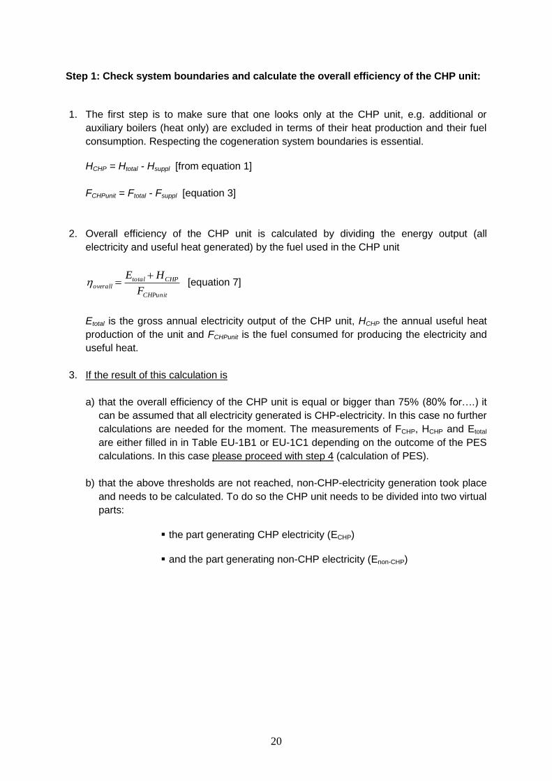
Step 1: Check system boundaries and calculate the overall efficiency of the CHP unit:
1. The first step is to make sure that one looks only at the CHP unit, e.g. additional or
auxiliary boilers (heat only) are excluded in terms of their heat production and their fuel
consumption. Respecting the cogeneration system boundaries is essential.
HCHP = Htotal - Hsuppl [from equation 1]
FCHPunit = Ftotal - Fsuppl [equation 3]
2. Overall efficiency of the CHP unit is calculated by dividing the energy output (all
electricity and useful heat generated) by the fuel used in the CHP unit
CHPunit
CHPtotaloverall
F
HE [equation 7]
Etotal is the gross annual electricity output of the CHP unit, HCHP the annual useful heat
production of the unit and FCHPunit is the fuel consumed for producing the electricity and
useful heat.
3. If the result of this calculation is
a) that the overall efficiency of the CHP unit is equal or bigger than 75% (80% for….) it
can be assumed that all electricity generated is CHP-electricity. In this case no further
calculations are needed for the moment. The measurements of FCHP, HCHP and Etotal
are either filled in in Table EU-1B1 or EU-1C1 depending on the outcome of the PES
calculations. In this case please proceed with step 4 (calculation of PES).
b) that the above thresholds are not reached, non-CHP-electricity generation took place
and needs to be calculated. To do so the CHP unit needs to be divided into two virtual
parts:
the part generating CHP electricity (ECHP)
and the part generating non-CHP electricity (Enon-CHP)
21
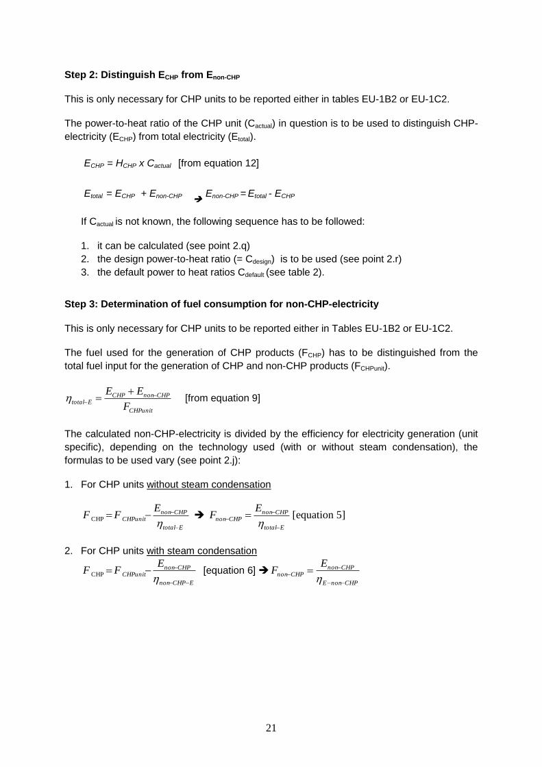
Step 2: Distinguish ECHP from Enon-CHP
This is only necessary for CHP units to be reported either in tables EU-1B2 or EU-1C2.
The power-to-heat ratio of the CHP unit (Cactual) in question is to be used to distinguish CHP-
electricity (ECHP) from total electricity (Etotal).
ECHP = HCHP x Cactual [from equation 12]
Etotal = ECHP + Enon-CHP
Enon-CHP = Etotal - ECHP
If Cactual is not known, the following sequence has to be followed:
1. it can be calculated (see point 2.q)
2. the design power-to-heat ratio (= Cdesign) is to be used (see point 2.r)
3. the default power to heat ratios Cdefault (see table 2).
Step 3: Determination of fuel consumption for non-CHP-electricity
This is only necessary for CHP units to be reported either in Tables EU-1B2 or EU-1C2.
The fuel used for the generation of CHP products (FCHP) has to be distinguished from the
total fuel input for the generation of CHP and non-CHP products (FCHPunit).
CHPunit
CHPnonCHPEtotal
F
EE
[from equation 9]
The calculated non-CHP-electricity is divided by the efficiency for electricity generation (unit
specific), depending on the technology used (with or without steam condensation), the
formulas to be used vary (see point 2.j):
1. For CHP units without steam condensation
Etotal
CHPnonCHPunit
EFF
CHP Etotal
CHPnonCHPnon
EF
[equation 5]
2. For CHP units with steam condensation
ECHPnon
CHPnonCHPunit
EFF
CHP [equation 6] CHPnonE
CHPnonCHPnon
EF
22
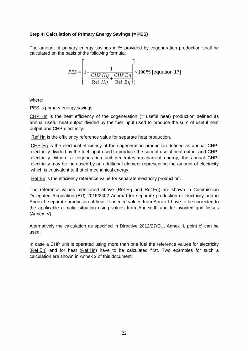
Step 4: Calculation of Primary Energy Savings (= PES)
The amount of primary energy savings in % provided by cogeneration production shall be calculated on the basis of the following formula:
100
RefRef
11
E
ECHP
H
HCHPPES % [equation 17]
where:
PES is primary energy savings.
CHP Hη is the heat efficiency of the cogeneration (= useful heat) production defined as
annual useful heat output divided by the fuel input used to produce the sum of useful heat
output and CHP-electricity.
Ref Hη is the efficiency reference value for separate heat production.
CHP Eη is the electrical efficiency of the cogeneration production defined as annual CHP-
electricity divided by the fuel input used to produce the sum of useful heat output and CHP-
electricity. Where a cogeneration unit generates mechanical energy, the annual CHP-
electricity may be increased by an additional element representing the amount of electricity
which is equivalent to that of mechanical energy.
Ref Eη is the efficiency reference value for separate electricity production.
The reference values mentioned above (Ref Hη and Ref Eη) are shown in Commission
Delegated Regulation (EU) 2015/2402 Annex I for separate production of electricity and in
Annex II separate production of heat. If needed values from Annex I have to be corrected to
the applicable climatic situation using values from Annex III and for avoided grid losses
(Annex IV).
Alternatively the calculation as specified in Directive 2012/27/EU, Annex II, point c) can be
used.
In case a CHP unit is operated using more than one fuel the reference values for electricity
(Ref Eη) and for heat (Ref Hη) have to be calculated first. Two examples for such a
calculation are shown in Annex 2 of this document.
23
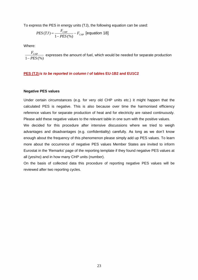
To express the PES in energy units (TJ), the following equation can be used:
CHPCHP F
PES
FTJPES
(%)1)( [equation 18]
Where:
(%)1 PES
FCHP
expresses the amount of fuel, which would be needed for separate production
PES (TJ) is to be reported in column I of tables EU-1B2 and EU1C2
Negative PES values
Under certain circumstances (e.g. for very old CHP units etc.) it might happen that the
calculated PES is negative. This is also because over time the harmonised efficiency
reference values for separate production of heat and for electricity are raised continuously.
Please add these negative values to the relevant table in one sum with the positive values.
We decided for this procedure after intensive discussions where we tried to weigh
advantages and disadvantages (e.g. confidentiality) carefully. As long as we don’t know
enough about the frequency of this phenomenon please simply add up PES values. To learn
more about the occurrence of negative PES values Member States are invited to inform
Eurostat in the 'Remarks' page of the reporting template if they found negative PES values at
all (yes/no) and in how many CHP units (number).
On the basis of collected data this procedure of reporting negative PES values will be
reviewed after two reporting cycles.
24
Step 5: Aggregation of fuels by fuel type for the generation of CHP products
In table EU-2 the fuel used for the generation of CHP products (useful heat and
CHP-electricity) is to be aggregated for 22 different fuel groups.
Operational CHP units, fuel used for CHP production
1) Hard coal:
consists of coking coal, anthracite, subbituminous coal and other bituminous coal. Its gross calorific value is greater than 20.000 kJ/kg on an ash-free but moist basis.
2) Sub-bituminous coal:
non-agglomerating coal with a gross calorific value between 20.000 kJ/kg and 24.000 kJ/kg containing more than 31 % volatile matter on a dry mineral matter free basis
3) Brown coal / lignite:
Lignite and brown coal: Non-agglomerating coal with a gross calorific value less than 20.000 kJ/kg and greater than 31% volatile matter on a dry mineral matter free basis.
Brown coal briquettes: a composition fuel manufactured from lignite or subbituminous coal, produced by briquetting under high pressure without the addition of a binding agent, including dried lignite fines and dust.
4) Peat:
a combustible soft, porous or compressed, fossil sedimentary deposit of plant origin with high water content (up to 90 % in the raw state), easily cut, of light to dark brown colour.
5) Peat products:
products such as peat briquettes derived directly or indirectly from sod peat and milled peat.
6) Coke-oven gas:
obtained as a by-product of the manufacture of coke oven coke for the production of iron and steel.
7) Blast furnace and oxygen steel furnace gas:
Gas recovered as by-product of blast furnaces and oxygen steel furnaces.
8) Other solid coal products:
Any other solid coal products not mentioned separately
9) Residual fuel oil:
this covers all residual (heavy) fuel oils (including those obtained by blending). Kinematic viscosity is above 10 cSt at 80°C. The flash point is always above 50°C and density is always more than 0.90 kg/l.
10) Refinery gas:
refinery gas includes a mixture of non-condensable gases mainly consisting of hydrogen, methane, ethane and olefins obtained during distillation of crude oil or treatment of oil products (e.g. cracking) in refineries. This also includes gases which are returned from the petrochemical industry.
25
11) Other liquid fossil fuels:
Any other liquid fossil fuels not mentioned separately, like gasoil, motor spirit, kerosenes and jet fuels etc.
12) Natural gas and gas works gas:
natural gas consists mainly of methane occurring naturally in underground deposits. This includes colliery gas. Gas works gas covers all types of gases produced in public utility or private plants, whose main purpose is manufacture, transport and distribution of gas.
13) Solid biomass:
covers organic, non-fossil material of biological origin which may be used as fuel for heat production or electricity generation. It comprises wood, wood residues and other solid wastes: covers purpose-grown energy crops (poplar, willow etc.), a multitude of woody materials generated by an industrial process (wood/paper industry in particular) or provided directly by forestry and agriculture (firewood, wood chips, bark, sawdust, shavings, chips, black liquor etc.) as well as wastes such as straw, rice husks, nut shells, poultry litter, crushed grape dregs etc.
14) Industrial waste:
wastes of industrial non-renewable origin (solids or liquids).
15) Municipal solid waste (renewable):
wastes produced by households, industry, hospitals and the tertiary sector which are biodegradable materials incinerated at specific installations.
16) Municipal solid waste (non-renewable):
wastes produced by households, industry, hospitals and the tertiary sector which are non-biodegradable materials incinerated at specific installations.
17) Biogases:
gas composed principally of methane and carbon dioxide produced by anaerobic digestion of biomass or by thermal processes from biomass and including biomass in waste. Biogas is a product aggregate equal to the sum of landfill gas, sewage sludge gas, other biogases from anaerobic digestion and biogases from thermal processes.
a) Landfill gas: Biogas produced form the anaerobic digestion of landfill waste.
b) Sewage sludge gas: Biogas produced from the anaerobic fermentation of sewage sludge.
c) Other biogases from anaerobic digestion: Biogas produced from the anaerobic fermentation of animal slurries and of waste in abattoirs, breweries and other agro-food industries.
d) Biogases from thermal processes: Biogas produced from thermal processes (by gasification or pyrolysis) of biomass.
18) Other renewables:
any other renewables and wastes not mentioned explicitly.
19) Nuclear heat:
heat released as a result of fission of the nuclear fuel inside the reactor.
20) Solar thermal:
heat from solar radiation for solar thermal-electric plants

26
21) Geothermal:
Energy available as heat emitted from within the earth's crust, usually in the form of hot water or steam. Used for electricity generation using dry steam or high enthalpy brine after flashing
22) Other fuels not mentioned above for example waste heat etc.
6. References
IDAE: Guía Técnica para la medida y determinación del calor útil, de la electricidad y del
ahorro de energía primaria de cogeneración de alta eficiencia
http://www.idae.es/uploads/documentos/documentos_guia_calculo_calor_util__hchp-echp-
pes_c24e48c1.pdf - an English version is also available – Spanish authorities informed that
these instructions are reworked at the moment and promised to inform Eurostat once a new version is available
Directive 2012/27/EU of the European Parliament and of the Council of 25 October 2012 on
energy efficiency, amending Directives 2009/125/EC and 2010/30/EU and repealing
Directives 2004/8/EC and 2006/32/EC
Commission Decision 2008/952/EU of 19 November 2008 establishing detailed guidelines for
the implementation and application of Annex II to Directive 2004/8/EC of the European
Parliament and of the Council
Commission delegated regulation (EU) 2015/2402 of 12 October 2015 reviewing harmonised
efficiency reference values for separate production of electricity and heat in application of
Directive 2012/27/EU of the European Parliament and of the Council and repealing
Commission Implementing Decision 2011/877/EU
27
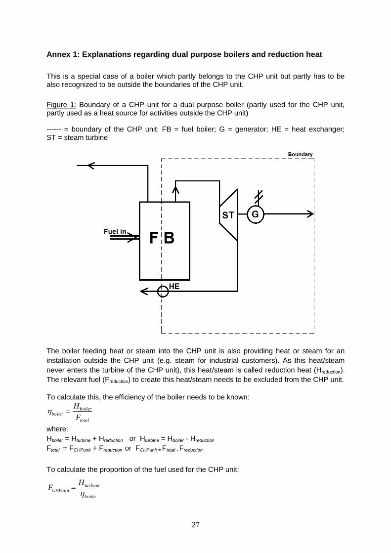
Annex 1: Explanations regarding dual purpose boilers and reduction heat
This is a special case of a boiler which partly belongs to the CHP unit but partly has to be also recognized to be outside the boundaries of the CHP unit.
Figure 1: Boundary of a CHP unit for a dual purpose boiler (partly used for the CHP unit, partly used as a heat source for activities outside the CHP unit)
------ = boundary of the CHP unit; FB = fuel boiler; G = generator; HE = heat exchanger; ST = steam turbine
The boiler feeding heat or steam into the CHP unit is also providing heat or steam for an
installation outside the CHP unit (e.g. steam for industrial customers). As this heat/steam
never enters the turbine of the CHP unit), this heat/steam is called reduction heat (Hreduction).
The relevant fuel (Freduction) to create this heat/steam needs to be excluded from the CHP unit.
To calculate this, the efficiency of the boiler needs to be known:
total
boilerboiler
F
H
where:
Hboiler = Hturbine + Hreduction or Hturbine = Hboiler - Hreduction
Ftotal = FCHPunit + Freduction or FCHPunit = Ftotal - Freduction
To calculate the proportion of the fuel used for the CHP unit:
boiler
turbineCHPunit
HF
28
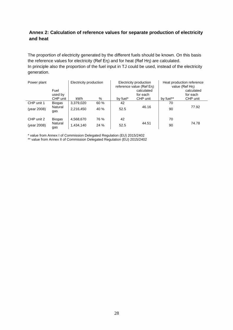
Annex 2: Calculation of reference values for separate production of electricity
and heat
The proportion of electricity generated by the different fuels should be known. On this basis
the reference values for electricity (Ref Eη) and for heat (Ref Hη) are calculated.
In principle also the proportion of the fuel input in TJ could be used, instead of the electricity
generation.
Power plant Electricity production Electricity production
reference value (Ref Eη) Heat production reference
value (Ref Hη)
Fuel used by CHP unit kWh % by fuel*
calculated for each CHP unit by fuel**
calculated for each CHP unit
CHP unit 1 Biogas 3,379,020 60 % 42 46.16
70 77.92
(year 2008) Natural gas
2,216,450 40 % 52.5 90
CHP unit 2 Biogas 4,568,670 76 % 42
44.51 70
74.78 (year 2008)
Natural gas
1,434,140 24 % 52.5 90
* value from Annex I of Commission Delegated Regulation (EU) 2015/2402 ** value from Annex II of Commission Delegated Regulation (EU) 2015/2402
29
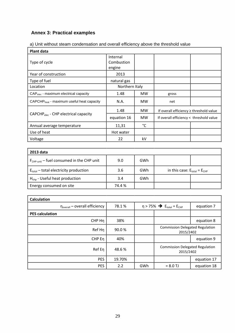
Annex 3: Practical examples
a) Unit without steam condensation and overall efficiency above the threshold value
Plant data
Type of cycle Internal Combustion engine
Year of construction 2013
Type of fuel natural gas
Location Northern Italy
CAPelec - maximum electrical capacity 1.48 MW gross
CAPCHPheat - maximum useful heat capacity N.A. MW net
CAPCHPelec - CHP electrical capacity 1.48 MW If overall efficiency ≥ threshold value
equation 16 MW If overall efficiency < threshold value
Annual average temperature 11,31 °C
Use of heat Hot water
Voltage 22 kV
2013 data
FCHP-unit – fuel consumed in the CHP unit 9.0 GWh
Etotal – total electricity production 3.6 GWh in this case: Etotal = ECHP
Hchp - Useful heat production 3.4 GWh
Energy consumed on site 74.4 %
Calculation
ƞoverall – overall efficiency 78.1 % ƞ > 75% Etotal = ECHP equation 7
PES calculation
CHP Hƞ 38%
equation 8
Ref Hƞ 90.0 %
Commission Delegated Regulation 2015/2402
CHP Eƞ 40%
equation 9
Ref Eƞ 48.6 %
Commission Delegated Regulation 2015/2402
PES 19.70%
equation 17
PES 2.2 GWh = 8.0 TJ equation 18
30
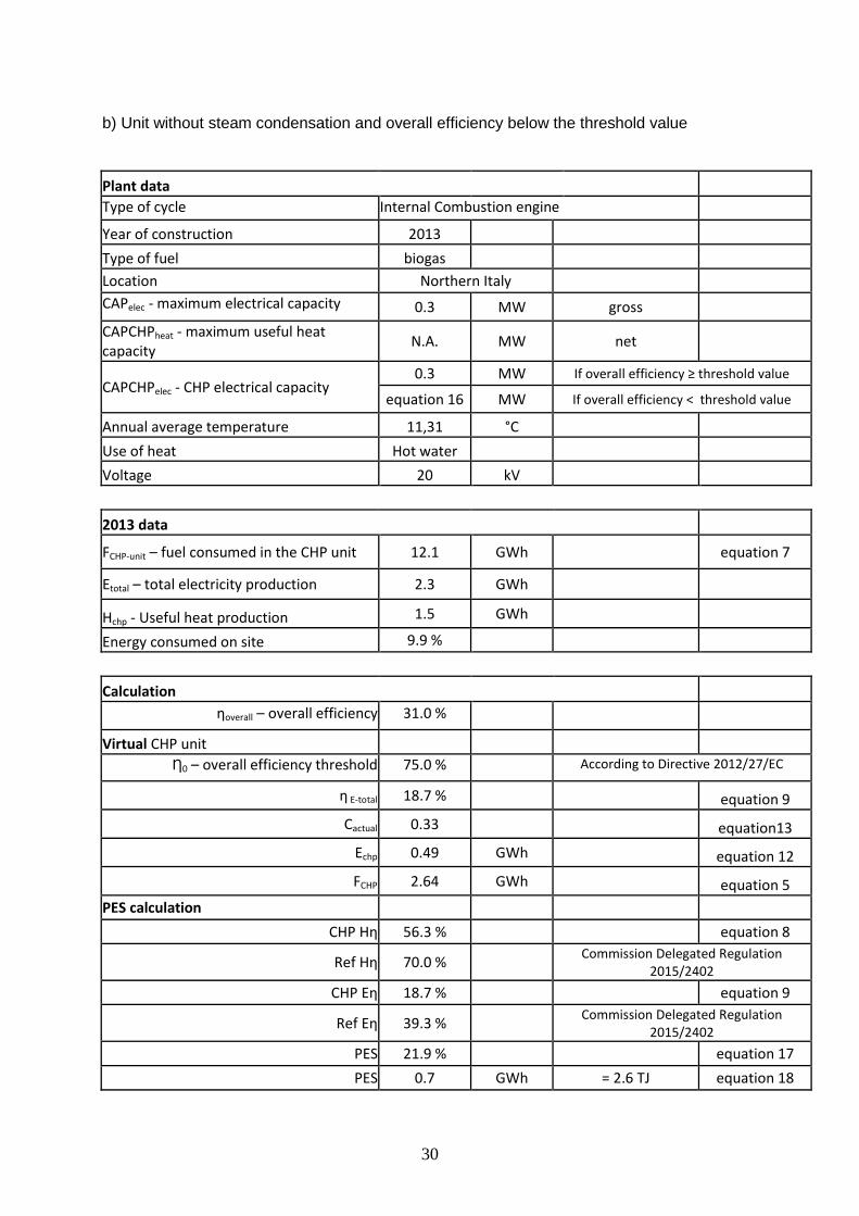
b) Unit without steam condensation and overall efficiency below the threshold value
Plant data
Type of cycle Internal Combustion engine
Year of construction 2013
Type of fuel biogas
Location Northern Italy
CAPelec - maximum electrical capacity 0.3 MW gross
CAPCHPheat - maximum useful heat capacity
N.A. MW net
CAPCHPelec - CHP electrical capacity 0.3 MW If overall efficiency ≥ threshold value
equation 16 MW If overall efficiency < threshold value
Annual average temperature 11,31 °C
Use of heat Hot water
Voltage 20 kV
2013 data
FCHP-unit – fuel consumed in the CHP unit 12.1 GWh
equation 7
Etotal – total electricity production 2.3 GWh
Hchp - Useful heat production 1.5 GWh
Energy consumed on site 9.9 %
Calculation
ƞoverall – overall efficiency 31.0 %
Virtual CHP unit
Ƞ0 – overall efficiency threshold 75.0 % According to Directive 2012/27/EC
ƞ E-total 18.7 %
equation 9
Cactual 0.33 equation13
Echp 0.49 GWh equation 12
FCHP 2.64 GWh equation 5
PES calculation
CHP Hƞ 56.3 %
equation 8
Ref Hƞ 70.0 %
Commission Delegated Regulation 2015/2402
CHP Eƞ 18.7 %
equation 9
Ref Eƞ 39.3 %
Commission Delegated Regulation 2015/2402
PES 21.9 %
equation 17
PES 0.7 GWh = 2.6 TJ equation 18
31
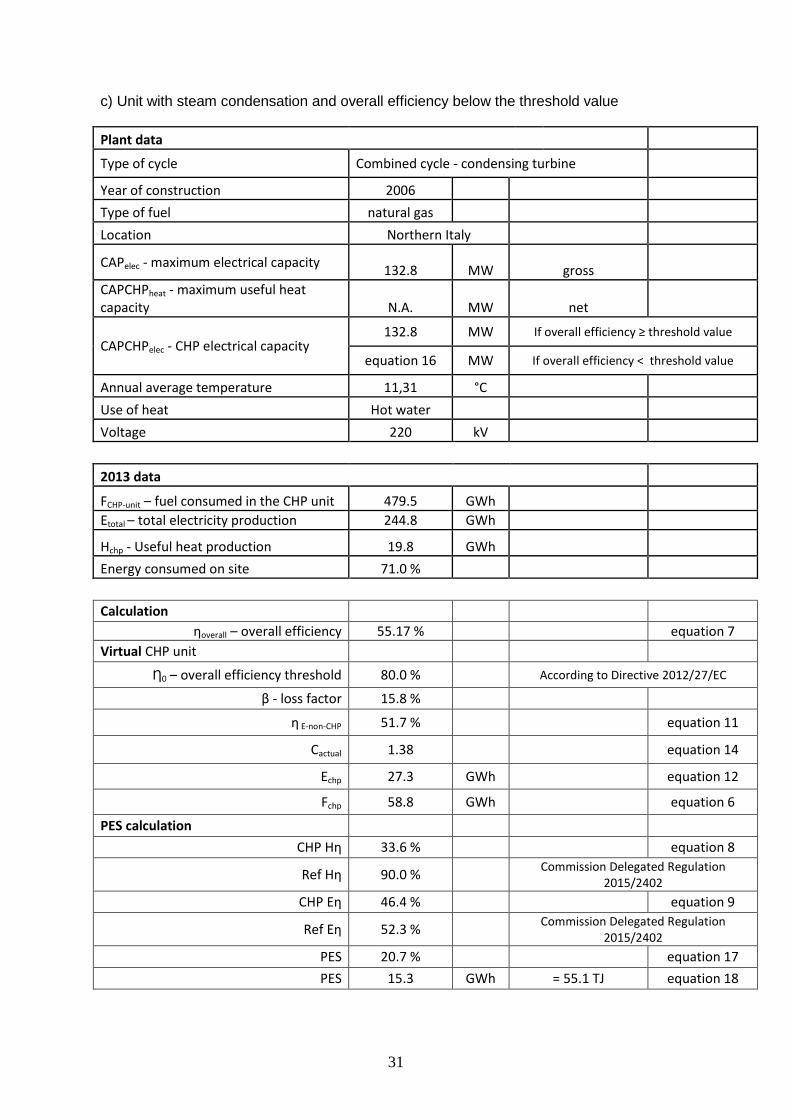
c) Unit with steam condensation and overall efficiency below the threshold value
Plant data
Type of cycle Combined cycle - condensing turbine
Year of construction 2006
Type of fuel natural gas
Location Northern Italy
CAPelec - maximum electrical capacity 132.8 MW gross
CAPCHPheat - maximum useful heat capacity N.A. MW net
CAPCHPelec - CHP electrical capacity 132.8 MW If overall efficiency ≥ threshold value
equation 16 MW If overall efficiency < threshold value
Annual average temperature 11,31 °C
Use of heat Hot water
Voltage 220 kV
2013 data
FCHP-unit – fuel consumed in the CHP unit 479.5 GWh
Etotal – total electricity production 244.8 GWh
Hchp - Useful heat production 19.8 GWh
Energy consumed on site 71.0 %
Calculation
ƞoverall – overall efficiency 55.17 %
equation 7
Virtual CHP unit
Ƞ0 – overall efficiency threshold 80.0 %
According to Directive 2012/27/EC
β - loss factor 15.8 %
ƞ E-non-CHP 51.7 %
equation 11
Cactual 1.38
equation 14
Echp 27.3 GWh
equation 12
Fchp 58.8 GWh
equation 6
PES calculation
CHP Hƞ 33.6 %
equation 8
Ref Hƞ 90.0 %
Commission Delegated Regulation 2015/2402
CHP Eƞ 46.4 %
equation 9
Ref Eƞ 52.3 %
Commission Delegated Regulation 2015/2402
PES 20.7 %
equation 17
PES 15.3 GWh = 55.1 TJ equation 18