Embed Size (px)
Citation preview

Combined heat and power & trigeneration solutions

2
Combined benefits of distributed cogeneration
Wärtsilä’s Smart Power Generation technology, with its fast starting and stopping capabilities, is an ultra-flexible complement to power production from wind and solar sources.
Wärtsilä’s combined heat and power (CHP) and trigeneration plants use fuel in the most efficient way and help to reduce carbon emission levels. Total plant efficiencies can exceed 90%. Our CHP plants are capable of running on various liquid, gaseous and bio fuels, while maintaining low emissions and high efficiency. Wärtsilä engine plants comply with national and local environmental requirements, and with the World Bank guidelines for power plants.
Thanks to the hang-on heat recovery system, Smart Power Generation CHP plants maintain high electrical efficiency and output, regardless of the heat production and ambient conditions. The products can be steam and hot or cold water.
In trigeneration power plants, Wärtsilä can deliver three valuable products for the customer: electricity, heating and cooling – all this from just one power plant. This is possible without compromising the high reliability and superb flexibility of the Wärtsilä power plants.
Wärtsilä offers CHP solutions to all customers with substantial heating demands, such as utilities and municipalities. Also large facilities, such as airports, shopping centers and other building complexes, can utilize Wärtsilä CHP and trigeneration solutions.
Wärtsilä’s development of distributed engine power plant solutions is based on the demand for alternative energy sources, the need to shorten transmission distances, and the increasing stipulations for fuel efficiency. With increased deregulation and the liberalisation of energy markets, the trend in many countries is towards decentralised systems. Power, heat and cooling need to be generated closer to consumers.
3
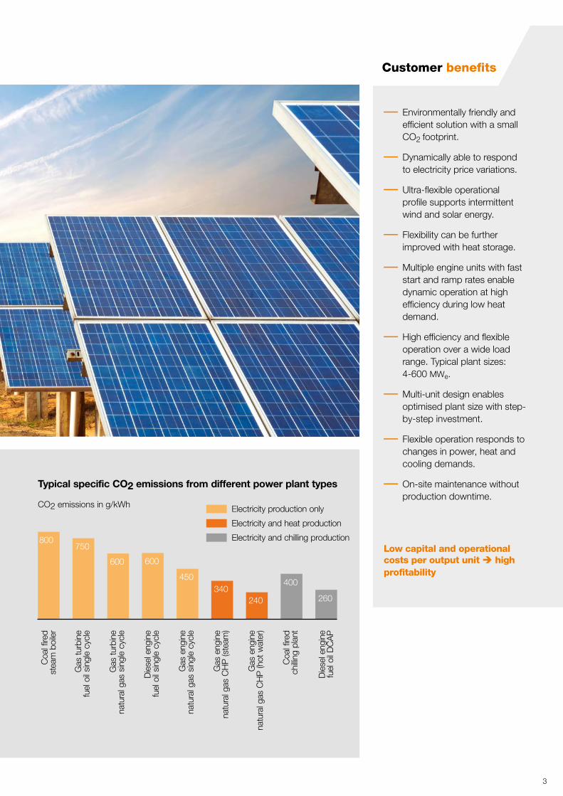
– Environmentally friendly and efficient solution with a small CO2 footprint.
– Dynamically able to respond to electricity price variations.
– Ultra-flexible operational profile supports intermittent wind and solar energy.
– Flexibility can be further improved with heat storage.
– Multiple engine units with fast start and ramp rates enable dynamic operation at high efficiency during low heat demand.
– High efficiency and flexible operation over a wide load range. Typical plant sizes: 4-600 MWe.
– Multi-unit design enables optimised plant size with step-by-step investment.
– Flexible operation responds to changes in power, heat and cooling demands.
– On-site maintenance without production downtime.
Low capital and operational costs per output unit è high profitability
Customer benefits
4
The heat recovery systems between the prime mover and the customer’s equipment, are typically “hang-on” solutions, ensuring both optimised heat production and effective engine cooling and operation. Wärtsilä’s heat recovery design takes into account all the seasonal, monthly, weekly and daily variations in the customer’s heat/cooling production conditions. Heat production does not affect the electrical output or the electrical efficiency of the prime mover.
Gas engine plant start-up times are very short – 100% electrical output is reached in 2 minutes and 100% heat output in less than 15 minutes.
The modular design of Wärtsilä CHP and trigeneration plants enables rapid delivery anywhere in the world. Prefabricated, functionally pre-tested modules guarantee
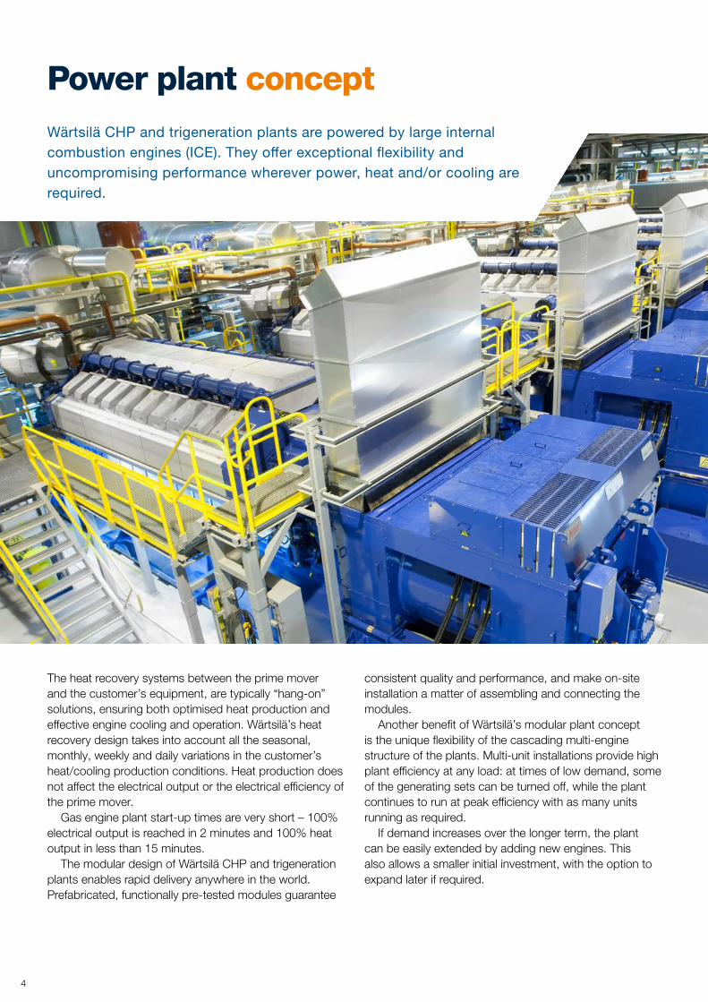
Power plant conceptWärtsilä CHP and trigeneration plants are powered by large internal combustion engines (ICE). They offer exceptional flexibility and uncompromising performance wherever power, heat and/or cooling are required.
consistent quality and performance, and make on-site installation a matter of assembling and connecting the modules.
Another benefit of Wärtsilä’s modular plant concept is the unique flexibility of the cascading multi-engine structure of the plants. Multi-unit installations provide high plant efficiency at any load: at times of low demand, some of the generating sets can be turned off, while the plant continues to run at peak efficiency with as many units running as required.
If demand increases over the longer term, the plant can be easily extended by adding new engines. This also allows a smaller initial investment, with the option to expand later if required.

The two-floor plant lay-out allows a small and compact footprint. The generating set and auxiliaries are on the first floor and the ventilation, exhaust gas heat recovery, and emission reduction equipment on the second floor.
5
CHP module
Wärtsilä 20V34SG
Engine Auxilliary Module (EAM)
Electrical power range of Wärtsilä generating sets

6
CHP solutions The high efficiency of Wärtsilä’s CHP plants translates into considerable savings in fuel costs compared to other technologies. For optimised profitability, the plants are customised to the customers’ specific needs.
A distributed combined heat and power plant increases reliability in the supply of energy. Energy production is local and close to the point of consumption. Local heat generation ensures quick response to changes in capacity or temperature in the industrial process or the district heating network.
To optimise the balance between thermal and electrical energy production, each plant is customised to suit the needs of the end user. Wärtsilä provides a design that ensures maximum efficiency and the best possible operational flexibility. The automation system not only controls all the internal processes in the Wärtsilä CHP plant, but is also carefully integrated with all necessary signals and connections to the existing systems, thereby guaranteeing a fully compatible plant.
For industrial applications (e.g. textile industry, food processing, refineries, etc.) steam can be produced for the processes. Fuel efficiency can be increased with steam production. Should the electricity grid be subject to failures, Wärtsilä engines guarantee a reliable supply of energy at all times.
Typical total plant efficiency as a function of the DH supply and return temperature.
Steam generation for industrial applications.
7
Steam generation for industrial applications.
8
Dynamic district heating solutions
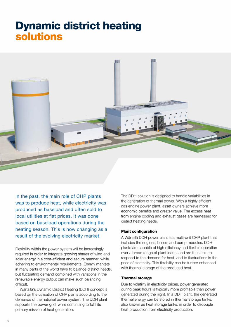
In the past, the main role of CHP plants was to produce heat, while electricity was produced as baseload and often sold to local utilities at flat prices. It was done based on baseload operations during the heating season. This is now changing as a result of the evolving electricity market.
Flexibility within the power system will be increasingly required in order to integrate growing shares of wind and solar energy in a cost-efficient and secure manner, while adhering to environmental requirements. Energy markets in many parts of the world have to balance distinct needs, but fluctuating demand combined with variations in the renewable energy output can make such balancing difficult.
Wärtsilä’s Dynamic District Heating (DDH) concept is based on the utilisation of CHP plants according to the demands of the national power system. The DDH plant supports the power grid, while continuing to fulfil its primary mission of heat generation.
The DDH solution is designed to handle variabilities in the generation of thermal power. With a highly efficient gas engine power plant, asset owners achieve more economic benefits and greater value. The excess heat from engine cooling and exhaust gases are harnessed for district heating needs.
Plant configuration
A Wärtsilä DDH power plant is a multi-unit CHP plant that includes the engines, boilers and pump modules. DDH plants are capable of high efficiency and flexible operation over a broad range of plant loads, and are thus able to respond to the demand for heat, and to fluctuations in the price of electricity. This flexibility can be further enhanced with thermal storage of the produced heat.
Thermal storage
Due to volatility in electricity prices, power generated during peak hours is typically more profitable than power generated during the night. In a DDH plant, the generated thermal energy can be stored in thermal storage tanks, also known as heat storage tanks, in order to decouple heat production from electricity production.
By combining the efficiency and flexibility of Wärtsilä engine technology with a tailored and optimised CHP process, a DDH plant can efficiently operate in electricity markets anywhere.
9
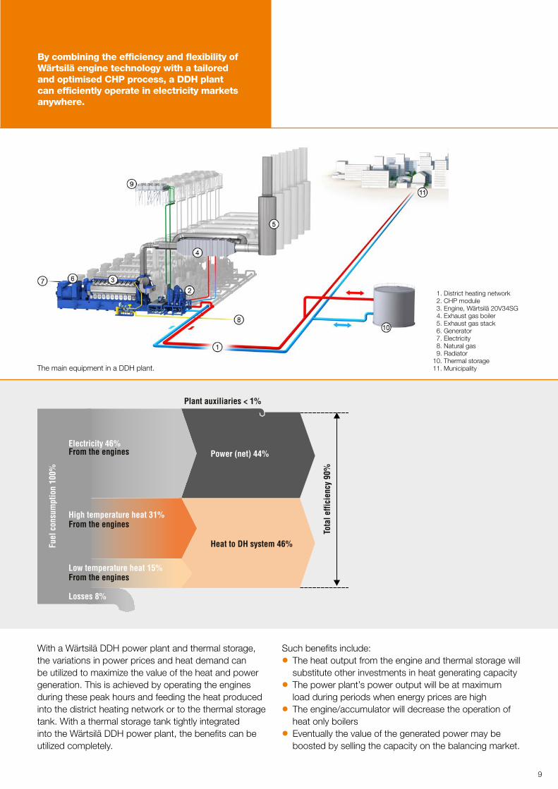
With a Wärtsilä DDH power plant and thermal storage, the variations in power prices and heat demand can be utilized to maximize the value of the heat and power generation. This is achieved by operating the engines during these peak hours and feeding the heat produced into the district heating network or to the thermal storage tank. With a thermal storage tank tightly integrated into the Wärtsilä DDH power plant, the benefits can be utilized completely.
The main equipment in a DDH plant.
1. District heating network 2. CHP module 3. Engine, Wärtsilä 20V34SG 4. Exhaust gas boiler 5. Exhaust gas stack 6. Generator 7. Electricity 8. Natural gas 9. Radiator10. Thermal storage11. Municipality
Such benefits include: z The heat output from the engine and thermal storage will substitute other investments in heat generating capacity
z The power plant’s power output will be at maximum load during periods when energy prices are high
z The engine/accumulator will decrease the operation of heat only boilers
z Eventually the value of the generated power may be boosted by selling the capacity on the balancing market.
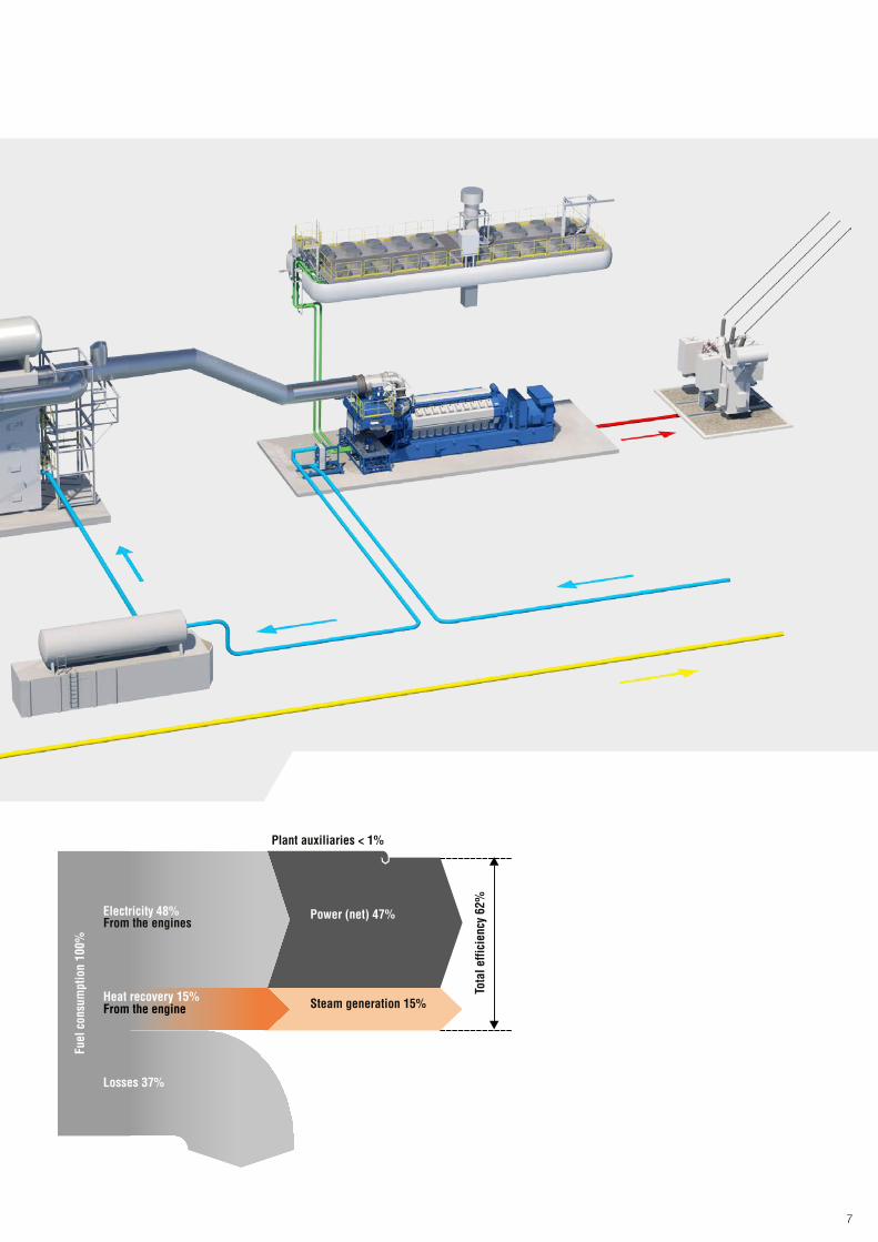
Power (net) 44%Electricity 46%
Fuel
con
sum
ptio
n 10
0%
From the engines
From the enginesHigh temperature heat 31%
Losses 8%
Heat to DH system 46%
Tota
l effi
cien
cy 9
0%
Plant auxiliaries < 1%
From the enginesLow temperature heat 15%

10
Trigeneration solutions While in many countries, district heating system technology is well established, in warmer climates the need is different. Here, where the yearly demand for heat is much less and the summer temperatures are high, cooling generation is essential.
While generating electric power, a substantial amount of cooling energy can be generated from the exhaust gas and engine waste heat by applying absorption chiller technology. Wärtsilä has designed its trigeneration plants to optimally meet the demand for both power and cooling.
Many industrial facilities and public buildings, such as airports, hospitals, shopping malls and large factories, have heating and cooling needs that can be efficiently met by a trigeneration plant. To maximise the total efficiency of a trigeneration plant, its location should ideally be close to the consumers.
Ambient conditions
Both electric power and cooling consumption are dependent on seasonal and daily demand variations. Cogeneration plants have to follow the load accordingly.
These variations can be very large, with ambient temperatures reaching 50 °C in the summer. Therefore, the fluctuations in electrical power consumption are also considerable. For example in the Middle East, 70% of the electricity produced is used for air conditioning.
DCAP solutions
The Wärtsilä District Cooling and Power (DCAP) system has been developed for hot areas where no heat is required, but only power and chilled water for district cooling and air conditioning.
These systems can be designed for 50,000 TR. The optimal solution is always based on the correct design and sizing. The entire chilled water demand should not be covered solely by absorption chillers. Instead, electrically driven chillers and/or chilled water storage tanks should be utilized to cover demand peaks, thereby minimizing

Case: Typical variation curves for a two engine trigeneration plant supplying electricity, heat and chilled water according to customer needs. Heat from the engines is utilized for heating during the winter period, and as an energy source for chillers during the summer. Thus, the plant’s heat recovery is efficiently used throughout the entire year.
Pow
er (n
et)
43–3
0%
Losses 23.0%
Cold
d w
ater
(net
)=
0.4–
0.7
kWe/
TR
Heat 31%
umpt
ion
100%
Fuel
cons
Heat to chiller 31%
(COP = 1)
Electricity 46%From the engines
From the engines
Electricity to TC-chiller 0–10% (COP = 5)
Tota
l effi
cien
cy 7
7.0%
Plant auxiliaries 1–3%
11
the total investment cost of the chiller capacity. The plant can provide both the required electricity and cooling, even during the hottest time of the year. When the engines feed electricity to the grid, all available waste heat is used efficiently for cooling. In case the chilled water cannot be utilized right away, the plant is able to run in pure electricity mode or charge the storage tanks so that no capacity is wasted.
DCAP reduces primary fuel usage by two thirds
The DCAP plant can obtain 0.6 kWe/TR with a storage tank and 0.7 kWe/TR without the tank. Compared to conventional centralised power plants or electrically driven compressor cooling plants installed on rooftops, this represents primary fuel savings of more than 60%.

12
Project executionWärtsilä has the resources and capabilities to fulfill contracts ranging from engineered equipment delivery (EEQ) to complete turnkey projects including engineering, procurement and construction (EPC). We have a proven track record of around 5000 projects in 176 countries.
With experienced and certified project execution personnel, Wärtsilä understands the requirements for power plant projects and is fully capable of handling and managing the complete range of contracting arrangements.
Capabilities: z Inter-disciplinary team of more than 200 project managers and project engineers with 100+ PMI-certified professionals.
z Certified HSE Management System OHSAS 18001 & ISO 14001. Lost Time Injury Frequency Rate ≈ 1.0 (EPC construction sites).
z Quality Management System ISO9001. z Efficient sourcing process and well-managed supplier base.
z Experienced construction management team of 400+ engineers.
z Established network of partners, engineering, manpower etc.
z Sustainable construction strategy utilizing qualified subcontractors, thus providing a positive socio-economic impact locally.

13
Services – lifecycle solutionsOur range of services covers everything from rapid spare parts delivery to complete long-term operation and maintenance solutions. By optimizing all aspects of the power plant’s operations and minimizing the economic and technological risks involved, we enhance the plant’s profitability.
Wärtsilä frequently enters into operation and maintenance (O&M) solutions with customers such as independent power producers (IPP), captive power plant operators, and baseload plant owners. These solutions are also suitable for balancing power plants, peaking/intermediate plants and utilities. They aim to maximize the productive lifetime of the installation and the return on investment. The solution is always tailored to the specific needs of the customer, including performance and lifecycle cost guarantees.
Wärtsilä currently operates more than 600 marine and land-based installations (24 GW of generating capacity) around the world.
If the customer chooses to operate the asset themselves, the best possible support is available – from training and online support to service packages or plant modernisation and upgrading. Our global services network of 11,000 professionals stands ready to provide support for our customers, anywhere at any time. This ensures that the power station will operate at its highest efficiency and performance levels throughout its lifetime.
Guaranteed asset performance
Guaranteed asset performance is a solution where Wärtsilä guarantees reliability and availability of the power plant with fixed cost. Customers can manage the operations and outsource the maintenance and its management to Wärtsilä.
The onsite support engineer, online data and remote monitoring enable advanced support and immediate response from Wärtsilä’s experts to ensure the safe operation of the power plant.

14
Broad experience on a global scale
KRAFTWERKE MAINZ-WIESBADEN
Customer Kraftwerke Mainz-Wiesbaden AGFuel GasPrime movers 10 x Wärtsilä 20V34SGElectrical power 100 MWeHeating power 93 MWthApplication Hot waterDelivery Heating period 2018
Wärtsilä has a track record of 63 GW of installed power generation capacity in 176 countries around the world. Our installed capacity of CHP plants totals approximately 11 GW. Here are some examples.
KAZAZOT
Customer KazAzot LLPFuel GasPrime movers 4 x Wärtsilä 20V34SGElectrical power 39 MWeHeating power 13 MWthApplication SteamDelivery 2017
CHEONG SOO
Customer JB Enertek Co., LtdFuel GasPrime movers 3 x Wärtsilä 20V34SGElectrical power 25.4 MWeHeating power 21.3 MWthApplication Hot waterDelivery 2010 & 2015
BOLGIANO
Customer Enipower SpA Fuel GasPrime movers 2 x Wärtsilä 20V34SG Electrical power 19.4 MWe Heating power 9 MWth Application Hot waterDelivery 2014
Mainz, Germany
Aktau, Kazakhstan
Cheon Ahn City, South Korea
San Donato Milanese, Italy

15
SASOLBURG
Customer Sasol New Energy (SNE)Fuel GasPrime movers 18 x Wärtsilä 20V34SGElectrical power 175 MWeSteam power 41.6 MWthApplication SteamDelivery 2012
LINATE AIRPORT
Customer Malpensa Energia SrlFuel GasPrime movers 3 x Wärtsilä 20V34SGElectrical power 24 MWeHeating power 17.5 MWthCooling capacity, total 14.0 MWcApplication Trigeneration Delivery 2007
ÚJPALOTA
Customer CHP Invest Kft.Fuel GasPrime movers 3 x Wärtsilä 20V34SGElectrical power 29 MWeHeating power 19 MWthApplication Hot waterDelivery 2004
BARAJAS AIRPORT
Customer AENAFuel Gas, LFOPrime movers 6 x Wärtsilä 18V32DFElectrical power 33.6 MWeHeating power 24 MWthCooling capacity, total 37.4 MWcApplication Trigeneration Delivery 2004
Sasolburg, South Africa
Milan, Italy
Budapest, Hungary
Madrid, Spain

Wärtsilä is a global leader in advanced technologies and complete lifecycle solutions for the marine and energy markets. By emphasising sustainable innovation and total efficiency, Wärtsilä maximises the environmental and economic performance of the vessels, power plants and LNG infrastructure of its customers.
wartsila.com
04.2
017
/ B
ock´
s O
ffice
WÄRTSILÄ® is a registered trademark. Copyright © 2017 Wärtsilä Corporation.
Specifications are subject to change without prior notice.