Embed Size (px)
Citation preview
Abstract— The study focuses on the optimization and design
of a dual heat-source-management system utilizing parallel
connection of solar thermal and biomass gasifier with a thermal
storage facility. The main objective is to supply constant and
ample heat energy to the ejector refrigeration system. Since
solar thermal energy is intermittent, it is best to store thermal
energy in a storage facility to have flexible energy source to
operate a heat driven system. Biomass gasifier provides
additional heat energy at night or during stormy weather or
cloudy sky condition.
Majority of studies related to this technology connects an
auxiliary heat source, directly to the vapor generator. Then, the
pair is connected in series with the thermal storage. The
drawback for this type of connection is the underutilized heat
from the gasifier to the vapor generator, since much of it needed
by the latter is just as much of that with the amount of heat given
by the solar thermal source. The excess heat will only be
exhausted as a waste heat by the refrigeration system.
An average annual solar fraction of 60% was set
corresponding to using an evacuated tube solar collector in the
calculation. Ambient temperature of 28℃ was. The condenser
temperature was set at 33℃, which is 5℃ above the ambient.
The thermal capacity of the gasifier was at 10 kW, while the area
of the solar collector was 9.21 m2 and the volume of the thermal
storage was set at 1 m3. The evaporator temperature was set at
15℃ intended for comfort cooling.
Using an algorithm, the solar collector efficiency was
calculated at 0.67. The simulation resulted to an average system
thermal ratio at around 0.265 and an ejector refrigeration
subsystem with COP of 0.30. The higher thermal ratio and COP
of the proposed setup with parallel connections of biomass
gasifier-boiler and solar thermal collector indicated that this
alternative system could be used to attain higher energy
efficiency in utilizing the sustainable heat sources. This research
also necessitates further investigation of the function and role of
the gasifier in using 3D CFD modelling and experimental
validation of the system.
Index Terms— evacuated tube, gasifier, heat-driven
refrigeration system, overall heat loss coefficient, thermal
energy storage
I. INTRODUCTION
HE Philippines is a tropical country and generally
throughout the year, the weather is humid and hot
specially during summer. Thus, space cooling for homes,
Manuscript received March 6, 2017. This work was supported in part by
Engineering Research and Development for Technology (ERDT) program of
the Department of Science and Technology –Science Education Institute
(DOST –SEI) of the Republic of the Philippines.
V. A. R. dela Cruz is a master of science student at the Department of
Mechanical Engineering, College of Engineering, University of the
offices and even commercial and industrial work places are
given priority to be safe, conducive for work and comfortable
to the occupants. Heat driven refrigeration system is the best
logical solution to these cooling requirements. Thus,
harnessing heat driven refrigeration technologies that would
operate on low grade energy source and at the same time
mitigate harmful effects to the environment brought about by
the refrigerants used in conventional vapor compression
systems, would suffice for the requirement. Ejector
refrigeration system is a heat-driven refrigeration cycle that
has the advantage of providing cooling effect even at low
grade thermal heat sources like solar, low-enthalpy
geothermal [1], and waste heat. Furthermore, the ejector
refrigeration system has minimal cost compared with other
heat driven systems like absorption refrigeration system [2].
The only drawback is the low coefficient of performance or
COP.
The Philippines has an abundance of natural resources with
the potential to provide energy to heat driven cooling
systems. It is located 1614 km above the equator [3] which
has ample solar energy available.
Annual solar irradiance in Metro Manila, the capital
Metropolis of the country, is on the average of about 4.34
kWh/m2-day [4]. This could provide ample heat to a medium
capacity cooling system, given appropriate considerations to
solar collector area, fluid flow rate, and collector’s tilt angle.
Also, being an agricultural country, the country has plenty
of biomass resources which include but not limited to
agricultural crop residues, forestry residues, agro-industrial
wastes, municipal solid wastes and aquatic biomass. Majority
of which are rice hull, bagasse, coconut shell/husks and
coconut coir. Biomass energy plays a vital role in the nation’s
energy supply [5].
The study investigates the effect of installing the biomass
heater as connected to the thermal storage in parallel with the
solar collector (Fig. 1), instead of installing the usual
auxiliary heater that is normally connected in series with
thermal storage and vapor generator [6].
Philippines - Diliman, Quezon City, 1101 Philippines (mobile phone: +63-
905-277-7232 and e-mail: [email protected]).
M. S. Berana is an associate professor in the Department of Mechanical
Engineering, associate dean in the College of Engineering, University of the
Philippines – Diliman, Quezon City, 1101 Philippines (phone: +63-906-214-
1782, +63-2-981-8500 loc 3130; fax: +63-2-709-8786; e-mail:
Combined Optimization of Solar Thermal and
Biomass Heat Sources with Thermal Storage for
the Design of an Ejector Refrigeration System
Vincent Aylmer R. dela Cruz and Menandro S. Berana
T
Proceedings of the World Congress on Engineering 2017 Vol II WCE 2017, July 5-7, 2017, London, U.K.
ISBN: 978-988-14048-3-1 ISSN: 2078-0958 (Print); ISSN: 2078-0966 (Online)
WCE 2017
II. REVIEW RELATED LITERATURE
A study by Colle et al. [7], employing simulation of a solar-
assisted ejector cooling system, investigated the validity of a
design methodology. The study focused on the hourly
simulation results for the computation of the solar fraction
with constant cooling capacity of the ejector cycle during
daily periods. The computed solar fraction is compared and
showed good agreement with estimates coming from the f-
chart method based on the utilization.
Refrigerant plays an important role in ejector refrigeration
system as studied by Sun [8]. It traditionally operates using
water but has low COP. Eleven refrigerants, including water,
halocarbon compounds, cyclic organic compound and
azeotrope are chosen and their performances in an ejector
refrigeration system are compared.
In a study by Pollerberg et al. [9], the setup has a solar
collector as its only heat source. Thus, providing heat to the
vapor generator only during day time, then from the generator
to the ejector. The study did not consider the continuous
operation of the system since solar energy is intermittent by
nature. It could have been better if there is a secondary or an
auxiliary heat source to compensate for the solar energy gap.
A study of a system having two heat sources, solar thermal
and biomass was done by Zhang et al. [10], but the two heat
sources operate as one is act as a prerequisite of the other. The
heat from the solar collector was used to produce steam
needed by the gasifier during the gasification process,
together with the other inputs like oxygen and the feedstock
from biomass. The resulting syngas will be used as fuel by
the internal combustion engine (ICE), supplying mechanical
energy to an electric generator. The heat driven refrigeration
system in this case is an absorption type that utilizes the
exhaust waste heat from ICE for heating of the aqua-ammonia
mixture. Even though the system has two heat inputs, the
solar energy operates simultaneously with the gasification
process. Thus, again dependent on the availability of the solar
energy for its continuous operation.
The study by Vidal et al. [11], utilizing dual heat sources,
solar and auxiliary for the ejector refrigeration system
incorporated a thermal storage. The system description starts
with the radiant energy captured by solar collector then
directing it to the thermal storage. Then, heat energy flows
from the thermal storage to the vapor generator that would
generate vaporized fluid and provide the primary flow to the
ejector. Between the vapor generator and the ejector there is
an auxiliary heat source. This energy back up provides
needed heat in cases energy lag from the solar collector.
The system done by Pridasawas and Lundqvist [2] added
an improvement. This also has dual heat source, solar and an
auxiliary heater for energy back up. Auxiliary heater is run
only by electricity with rated capacity. The solar collector is
the main heat source of the ejector refrigeration system
connected to the thermal storage, and then to the auxiliary
heat source, which provides heat during power fluctuation.
The auxiliary heater is then connected to the vapor generator
that vaporizes refrigerant as primary fluid to the ejector. This
together with the previously mentioned studies regarding
energy management configurations that have dual heat
sources, are almost the same but having different locations of
the auxiliary heater. The previous one is located between the
generator and the ejector. In the latter, auxiliary heater is
installed between the thermal storage tank and the vapor
generator.
III. SYSTEM DESCRIPTION AND MODELLING
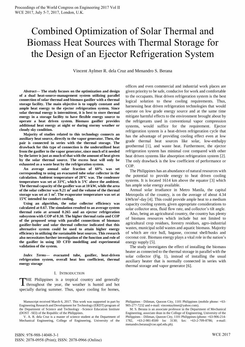
The system is divided into two subsystems: the dual heat
source subsystem and ejector refrigeration subsystem. The
dual heat source subsystem composes of the solar collector
and the biomass-gasifier-boiler that would provide heat for
the refrigeration system. Both heat source components are
connected in parallel to the thermal storage tank. The solar
thermal collector would be the main energy source and it is
backed up by the biomass heat source. The refrigeration
system is composed of the vapor generator, ejector,
condenser, pump, thermostatic expansion valve and
evaporator. The cooling load for the refrigeration system is
set as 3.517 kW at evaporator temperature of 15℃.
A. The dual heat source subsystem
As shown in Fig. 1, the dual heat source subsystem will be
installed in such a way that the solar collector would be
connected in parallel with the biomass-gasifier-boiler making
the thermal storage located in between them.
Solar Collectors
Solar collectors that are commonly employed for this
purpose are flat plate-single glazed, flat plate-double glazed
and evacuated tube because of economy and efficiency.
Previous studies supported the superiority of evacuated
tube over flat plate collectors [12]. Since solar collector
efficiency is a function of heat loss coefficient, the evacuated
tube collector is characterized with reduced internal
conduction and convection losses which results to higher
thermal efficiency even at low incident angle compared with
the flat plate collector.
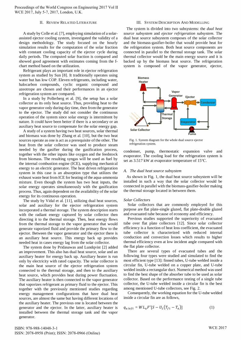
There are several types of evacuated tubes and the
following four types were studied and simulated to find the
most efficient type [13]: finned tubes, U-tube welded inside a
circular fin, U-tube welded on a copper plate, and U-tube
welded inside a rectangular duct. Numerical method was used
to find the best shape of the absorber tube to be used as solar
collector. Based on the performance testing of a single tube
collector, the U-tube welded inside a circular fin is the best
among mentioned U-tube collectors, see Fig. 2.
Consequently, the working equation for the U-tube welded
inside a circular fin are as follows,
𝑞𝑢 𝑙𝑒𝑓𝑡 = 𝑊𝐿𝑢𝐹′[𝑆 − 𝑈𝐿(𝑇𝑓1 − 𝑇𝑎)] (1)
Fig. 1. System diagram for the whole dual source ejector
refrigeration system.
Proceedings of the World Congress on Engineering 2017 Vol II WCE 2017, July 5-7, 2017, London, U.K.
ISBN: 978-988-14048-3-1 ISSN: 2078-0958 (Print); ISSN: 2078-0966 (Online)
WCE 2017
𝑞𝑢 𝑟𝑖𝑔ℎ𝑡 = 𝑊𝐿𝑢𝐹′[𝑆 − 𝑈𝐿(𝑇𝑓2 − 𝑇𝑎)] (2)
where qu, left is the heat transfer by conduction at the point of
contact between the fin and the tube at the left side of the U-
tube where Tin and Tmid exist. qu, right is the heat transfer by
conduction at the point of contact between the fin and the tube
at the right side of the U-tube where Tmid and Tout exist. W is
the circumferential distance between U-tubes, W= P/2 in
meters and P is the overall perimeter of the fin. Lu is the length
of U-tube per left or right side. F’ is the collector efficiency
factor. S is the solar energy absorbed by the selective
absorbing coating. UL is the overall heat loss coefficient, with
a range value of 2-4 W/m2-K, based on experimental and
theoretical evaluation [14]. Tf1 and Tf2 are the average
working fluid temperatures in the two sides of the tubes.
Also,
𝑇𝑓1 = (𝑇𝑖𝑛+ 𝑇𝑚𝑖𝑑)
2 (3)
𝑇𝑓2 = (𝑇𝑚𝑖𝑑+ 𝑇𝑜𝑢𝑡)
2 (4)
where, Tin and Tout are the inlet and outlet temperatures of the
working fluid in the U-tube, respectively. And Tmid is the
temperature of the working fluid at the tube bend. Thus, the
temperature of the working fluid can be obtained by the
following equations based on (1) and (2).
Consequently,
𝑞𝑢 𝑙𝑒𝑓𝑡 = 𝑚 𝐶𝑝𝑓 (𝑇𝑚𝑖𝑑 − 𝑇𝑖𝑛) (5)
𝑞𝑢 𝑟𝑖𝑔ℎ𝑡 = 𝑚 𝐶𝑝𝑓 (𝑇𝑜𝑢𝑡 − 𝑇𝑚𝑖𝑑) (6)
Then combining (5) and (6) with Tmid as common variable
for the heat capacity of the whole single evacuated U- tube
copper fin
𝑞𝑢 𝑙𝑒𝑓𝑡+ 𝑞𝑢 𝑟𝑖𝑔ℎ𝑡 = 𝑞𝑢 𝑡𝑜𝑡𝑎𝑙 (7)
From (7) that represents the heat output of a single
evacuated tube, the calculated capacity is 51.32 W. The
system need 172 tubes. With a total solar collector aperture
area of 9.21 m2, the total energy output of the collector is 8.83
kW.
The solar collector efficiency is calculated using the
formula,
𝜂 =(𝑞𝑢,𝑇𝑜𝑡𝑎𝑙) (𝑁𝑡𝑢𝑏𝑒𝑠)
𝐼𝑜 𝐴𝑝 (8)
where η is the solar collector efficiency. Ntubes for the number
of evacuated tubes needed to supply required heat energy to
the system. Io is for the solar radiation intensity. Ap is the
diffuse reflection area of solar collector, Ap = 2DL. D is the
outer diameter of the absorber tube, L is the length of the
absorber tube.
The solar fraction (f) is the ratio between heat energy
supplied by the solar collector and the total energy
requirement of the cooling system
𝑓 =𝑄𝑢
𝑄𝑠𝑡𝑜𝑟𝑎𝑔𝑒 (9)
Given in Table I are the parameters used in the calculation
for the optimal operation of the evacuated tube solar
collector.
Thermal Energy Storage
The common working fluid used for storing thermal energy
is water because of its high specific heat which is 4.187 kJ/kg-
K. Water is used both as energy storing and transporting
medium. This is done to prevent heat transfer losses between
the storing medium and transport medium as compared to
using different fluids [16].
One among the major objectives of the study is to
investigate for the improvement of the system and its
correlation with the physical arrangement of the solar
collector and the biomass-gasifier-boiler connected in
parallel to the thermal energy storage tank. Simple sensible
thermal storage type is adopted in the study due to its
simplicity and established principles compared with the other
two types which are phase change and chemical reaction type
of thermal storage materials. Given that water or any kind of
working fluid has a uniform temperature, fully mixed or
Material Parameters Quantity Unit
Absorbing coating Absorptivity (α) 0.92
Emmissivity (εp) 0.08
Outer glass tube Outer diameter 47 mm
Thickness 1.2 mm
Conductivity 1.2 W/m-K
Absorber tube Outer diameter 37 mm
Thickness 1.2 mm
Conductivity 1.2 W/m-K
Copper fin Thickness 0.6 mm
Conductivity 307 W/m-K
Air layer Thickness 1 mm
Conductivity 0.03 W/m-K
U-tube Outer diameter 8 mm
h f,i 700 W/m2-K
Length of the tubular collector 1200 mm
Bond conductance 30 W/m-K
TABLE I
PARAMETERS OF EVACUATED TUBE SOLAR COLLECTOR [15] Fig. 2. Cross section of glass evacuated tube with U- tube.
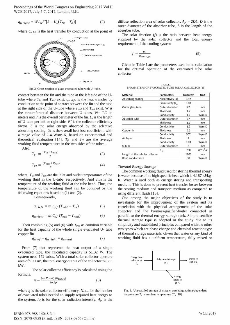
Fig. 3. Unstratified storage of mass m operating at time-dependent
temperature Ts in ambient temperature T’a [16]
Proceedings of the World Congress on Engineering 2017 Vol II WCE 2017, July 5-7, 2017, London, U.K.
ISBN: 978-988-14048-3-1 ISSN: 2078-0958 (Print); ISSN: 2078-0966 (Online)
WCE 2017
unstratified then operating at a definite temperature
difference is given by
𝑄𝑠𝑡𝑜𝑟𝑎𝑔𝑒 = (𝑚𝐶𝑝)𝑠 ∆𝑇𝑠 (10)
where Qs is the total heat capacity for the cycle operating
through temperature range ∆Ts, m is the mass of water in the
unit and Cp is the specific heat of the working fluid. The
operating temperature range where the unit operate is
determined and limited at the lower extreme by the
requirement of the load or process to be served. The upper
limit is determined also by the process, which is the vapor
pressure of the working liquid and heat loss in the collector.
The energy balance of the unstratified tank shown
in Fig. 3 is
(𝑚𝐶𝑝)𝑠
𝑑𝑇𝑠
𝑑𝑡= 𝑄𝑢 − 𝐿�̇� − (𝑈𝐴)𝑠 (𝑇𝑠 − 𝑇′𝑎) (11)
Where Qu is the rate of energy addition from the solar
collector to the storage. L̇s is the rate of energy extraction of
the load, (UA)s is the heat loss coefficient. T’a is the ambient
temperature in the location of the storage tank, which is
different from the ambient air of the collector.
After the calculation using simple Euler integration by
rewriting the temperature derivative as (T+s - Ts)/ ∆t, the
resulting energy balance, hence follows as
(𝑚𝐶𝑝)𝑠
(𝑇′𝑠− 𝑇𝑠)
∆𝑡= 𝑄𝑢 − 𝐿𝑠 − (𝑈𝐴)𝑠 (𝑇𝑠 − 𝑇′𝑎) (12)
Where, Ts’ is the temperature of the storage after the time
increment ∆t usually per hour. Then the following is obtained
upon solving for the tank temperature at the end of each time
increment
𝑇′𝑠 = 𝑇𝑠 + ∆𝑡
(𝑚𝐶𝑝)𝑠
[𝑄𝑢 − 𝐿𝑠 − (𝑈𝐴)𝑠 (𝑇𝑠 − 𝑇′𝑎)] (13)
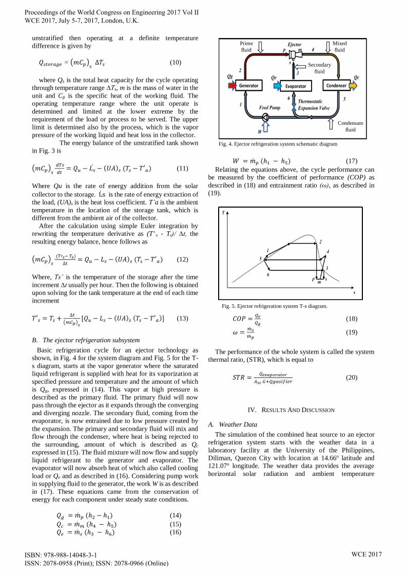
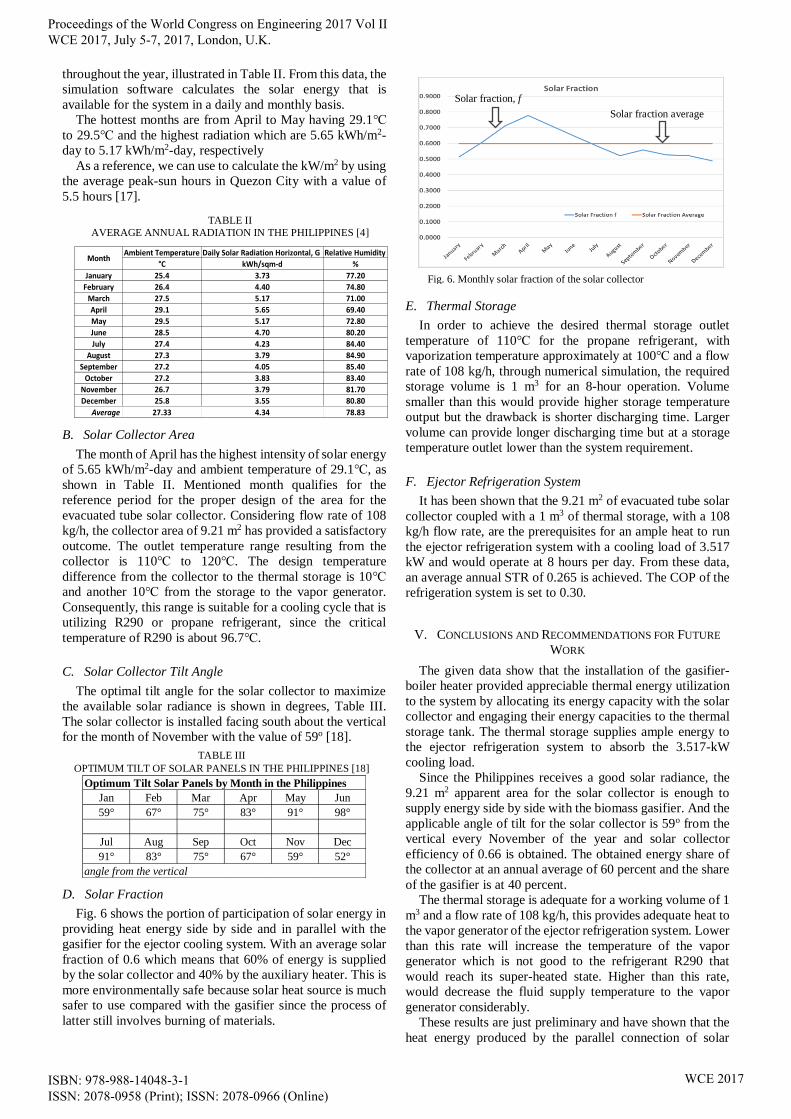
B. The ejector refrigeration subsystem
Basic refrigeration cycle for an ejector technology as
shown, in Fig. 4 for the system diagram and Fig. 5 for the T-
s diagram, starts at the vapor generator where the saturated
liquid refrigerant is supplied with heat for its vaporization at
specified pressure and temperature and the amount of which
is Qg, expressed in (14). This vapor at high pressure is
described as the primary fluid. The primary fluid will now
pass through the ejector as it expands through the converging
and diverging nozzle. The secondary fluid, coming from the
evaporator, is now entrained due to low pressure created by
the expansion. The primary and secondary fluid will mix and
flow through the condenser, where heat is being rejected to
the surrounding, amount of which is described as Qc
expressed in (15). The fluid mixture will now flow and supply
liquid refrigerant to the generator and evaporator. The
evaporator will now absorb heat of which also called cooling
load or Qe and as described in (16). Considering pump work
in supplying fluid to the generator, the work W is as described
in (17). These equations came from the conservation of
energy for each component under steady state conditions.
𝑄𝑔 = �̇�𝑝 (ℎ2 − ℎ1) (14)
𝑄𝑐 = �̇�𝑚 (ℎ4 − ℎ5) (15)
𝑄𝑒 = �̇�𝑠 (ℎ3 − ℎ6) (16)
𝑊 = �̇�𝑝 (ℎ1 − ℎ5) (17)
Relating the equations above, the cycle performance can
be measured by the coefficient of performance (COP) as
described in (18) and entrainment ratio (ω), as described in
(19).
𝐶𝑂𝑃 =𝑄𝑒
𝑄𝑔 (18)
𝜔 =�̇�𝑠
�̇�𝑝 (19)
The performance of the whole system is called the system
thermal ratio, (STR), which is equal to
𝑆𝑇𝑅 =𝑄𝑒𝑣𝑎𝑝𝑜𝑟𝑎𝑡𝑜𝑟
𝐴𝑠𝑐 𝐺+𝑄𝑔𝑎𝑠𝑖𝑓𝑖𝑒𝑟 (20)
IV. RESULTS AND DISCUSSION
A. Weather Data
The simulation of the combined heat source to an ejector
refrigeration system starts with the weather data in a
laboratory facility at the University of the Philippines,
Diliman, Quezon City with location at 14.66o latitude and
121.07o longitude. The weather data provides the average
horizontal solar radiation and ambient temperature
Fig. 5. Ejector refrigeration system T-s diagram.
Fig. 4. Ejector refrigeration system schematic diagram
Prime
fluid
Mixed
fluid
Secondary
fluid
Condensate
fluid
Proceedings of the World Congress on Engineering 2017 Vol II WCE 2017, July 5-7, 2017, London, U.K.
ISBN: 978-988-14048-3-1 ISSN: 2078-0958 (Print); ISSN: 2078-0966 (Online)
WCE 2017
throughout the year, illustrated in Table II. From this data, the
simulation software calculates the solar energy that is
available for the system in a daily and monthly basis.
The hottest months are from April to May having 29.1℃
to 29.5℃ and the highest radiation which are 5.65 kWh/m2-
day to 5.17 kWh/m2-day, respectively
As a reference, we can use to calculate the kW/m2 by using
the average peak-sun hours in Quezon City with a value of
5.5 hours [17].
B. Solar Collector Area
The month of April has the highest intensity of solar energy
of 5.65 kWh/m2-day and ambient temperature of 29.1℃, as
shown in Table II. Mentioned month qualifies for the
reference period for the proper design of the area for the
evacuated tube solar collector. Considering flow rate of 108
kg/h, the collector area of 9.21 m2 has provided a satisfactory
outcome. The outlet temperature range resulting from the
collector is 110℃ to 120℃. The design temperature
difference from the collector to the thermal storage is 10℃
and another 10℃ from the storage to the vapor generator.
Consequently, this range is suitable for a cooling cycle that is
utilizing R290 or propane refrigerant, since the critical
temperature of R290 is about 96.7℃.
C. Solar Collector Tilt Angle
The optimal tilt angle for the solar collector to maximize
the available solar radiance is shown in degrees, Table III.
The solar collector is installed facing south about the vertical
for the month of November with the value of 59o [18].
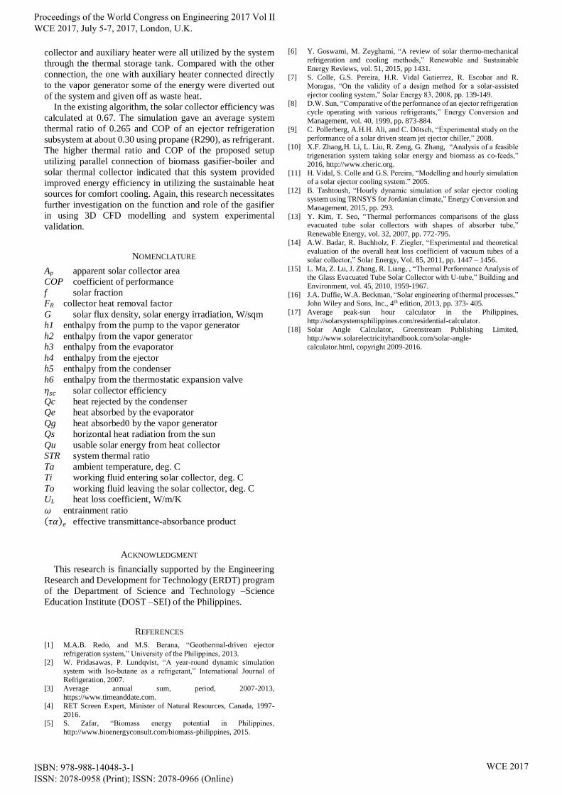
D. Solar Fraction
Fig. 6 shows the portion of participation of solar energy in
providing heat energy side by side and in parallel with the
gasifier for the ejector cooling system. With an average solar
fraction of 0.6 which means that 60% of energy is supplied
by the solar collector and 40% by the auxiliary heater. This is
more environmentally safe because solar heat source is much
safer to use compared with the gasifier since the process of
latter still involves burning of materials.
E. Thermal Storage
In order to achieve the desired thermal storage outlet
temperature of 110℃ for the propane refrigerant, with
vaporization temperature approximately at 100℃ and a flow
rate of 108 kg/h, through numerical simulation, the required
storage volume is 1 m3 for an 8-hour operation. Volume
smaller than this would provide higher storage temperature
output but the drawback is shorter discharging time. Larger
volume can provide longer discharging time but at a storage
temperature outlet lower than the system requirement.
F. Ejector Refrigeration System
It has been shown that the 9.21 m2 of evacuated tube solar
collector coupled with a 1 m3 of thermal storage, with a 108
kg/h flow rate, are the prerequisites for an ample heat to run
the ejector refrigeration system with a cooling load of 3.517
kW and would operate at 8 hours per day. From these data,
an average annual STR of 0.265 is achieved. The COP of the
refrigeration system is set to 0.30.
V. CONCLUSIONS AND RECOMMENDATIONS FOR FUTURE
WORK
The given data show that the installation of the gasifier-
boiler heater provided appreciable thermal energy utilization
to the system by allocating its energy capacity with the solar
collector and engaging their energy capacities to the thermal
storage tank. The thermal storage supplies ample energy to
the ejector refrigeration system to absorb the 3.517-kW
cooling load.
Since the Philippines receives a good solar radiance, the
9.21 m2 apparent area for the solar collector is enough to
supply energy side by side with the biomass gasifier. And the
applicable angle of tilt for the solar collector is 59o from the
vertical every November of the year and solar collector
efficiency of 0.66 is obtained. The obtained energy share of
the collector at an annual average of 60 percent and the share
of the gasifier is at 40 percent.
The thermal storage is adequate for a working volume of 1
m3 and a flow rate of 108 kg/h, this provides adequate heat to
the vapor generator of the ejector refrigeration system. Lower
than this rate will increase the temperature of the vapor
generator which is not good to the refrigerant R290 that
would reach its super-heated state. Higher than this rate,
would decrease the fluid supply temperature to the vapor
generator considerably.
These results are just preliminary and have shown that the
heat energy produced by the parallel connection of solar
TABLE II
AVERAGE ANNUAL RADIATION IN THE PHILIPPINES [4]
Ambient Temperature Daily Solar Radiation Horizontal, G Relative Humidity
°C kWh/sqm-d %
January 25.4 3.73 77.20
February 26.4 4.40 74.80
March 27.5 5.17 71.00
April 29.1 5.65 69.40
May 29.5 5.17 72.80
June 28.5 4.70 80.20
July 27.4 4.23 84.40
August 27.3 3.79 84.90
September 27.2 4.05 85.40
October 27.2 3.83 83.40
November 26.7 3.79 81.70
December 25.8 3.55 80.80
Average 27.33 4.34 78.83
Month
TABLE III
OPTIMUM TILT OF SOLAR PANELS IN THE PHILIPPINES [18]
Jan Feb Mar Apr May Jun
59° 67° 75° 83° 91° 98°
Jul Aug Sep Oct Nov Dec
91° 83° 75° 67° 59° 52°
angle from the vertical
Optimum Tilt Solar Panels by Month in the Philippines
Fig. 6. Monthly solar fraction of the solar collector
Solar fraction, f
Solar fraction average
Proceedings of the World Congress on Engineering 2017 Vol II WCE 2017, July 5-7, 2017, London, U.K.
ISBN: 978-988-14048-3-1 ISSN: 2078-0958 (Print); ISSN: 2078-0966 (Online)
WCE 2017
collector and auxiliary heater were all utilized by the system
through the thermal storage tank. Compared with the other
connection, the one with auxiliary heater connected directly
to the vapor generator some of the energy were diverted out
of the system and given off as waste heat.
In the existing algorithm, the solar collector efficiency was
calculated at 0.67. The simulation gave an average system
thermal ratio of 0.265 and COP of an ejector refrigeration
subsystem at about 0.30 using propane (R290), as refrigerant.
The higher thermal ratio and COP of the proposed setup
utilizing parallel connection of biomass gasifier-boiler and
solar thermal collector indicated that this system provided
improved energy efficiency in utilizing the sustainable heat
sources for comfort cooling. Again, this research necessitates
further investigation on the function and role of the gasifier
in using 3D CFD modelling and system experimental
validation.
NOMENCLATURE
Ap apparent solar collector area
COP coefficient of performance
f solar fraction
FR collector heat removal factor
G solar flux density, solar energy irradiation, W/sqm
h1 enthalpy from the pump to the vapor generator
h2 enthalpy from the vapor generator
h3 enthalpy from the evaporator
h4 enthalpy from the ejector
h5 enthalpy from the condenser
h6 enthalpy from the thermostatic expansion valve
𝜂𝑠𝑐 solar collector efficiency
Qc heat rejected by the condenser
Qe heat absorbed by the evaporator
Qg heat absorbed0 by the vapor generator
Qs horizontal heat radiation from the sun
Qu usable solar energy from heat collector
STR system thermal ratio
Ta ambient temperature, deg. C
Ti working fluid entering solar collector, deg. C
To working fluid leaving the solar collector, deg. C
UL heat loss coefficient, W/m/K
𝜔 entrainment ratio (𝜏𝛼)𝑒 effective transmittance-absorbance product
ACKNOWLEDGMENT
This research is financially supported by the Engineering
Research and Development for Technology (ERDT) program
of the Department of Science and Technology –Science
Education Institute (DOST –SEI) of the Philippines.
REFERENCES
[1] M.A.B. Redo, and M.S. Berana, “Geothermal-driven ejector
refrigeration system,” University of the Philippines, 2013.
[2] W. Pridasawas, P. Lundqvist, “A year-round dynamic simulation
system with Iso-butane as a refrigerant,” International Journal of
Refrigeration, 2007.
[3] Average annual sum, period, 2007-2013,
https://www.timeanddate.com.
[4] RET Screen Expert, Minister of Natural Resources, Canada, 1997-
2016.
[5] S. Zafar, “Biomass energy potential in Philippines,
http://www.bioenergyconsult.com/biomass-philippines, 2015.
[6] Y. Goswami, M. Zeyghami, “A review of solar thermo-mechanical
refrigeration and cooling methods,” Renewable and Sustainable
Energy Reviews, vol. 51, 2015, pp 1431.
[7] S. Colle, G.S. Pereira, H.R. Vidal Gutierrez, R. Escobar and R.
Moragas, “On the validity of a design method for a solar-assisted
ejector cooling system,” Solar Energy 83, 2008, pp. 139-149.
[8] D.W. Sun, “Comparative of the performance of an ejector refrigeration
cycle operating with various refrigerants,” Energy Conversion and
Management, vol. 40, 1999, pp. 873-884.
[9] C. Pollerberg, A.H.H. Ali, and C. Dötsch, “Experimental study on the
performance of a solar driven steam jet ejector chiller,” 2008.
[10] X.F. Zhang,H. Li, L. Liu, R. Zeng, G. Zhang, “Analysis of a feasible
trigeneration system taking solar energy and biomass as co-feeds,”
2016, http://www.cheric.org.
[11] H. Vidal, S. Colle and G.S. Pereira, “Modelling and hourly simulation
of a solar ejector cooling system.” 2005.
[12] B. Tashtoush, “Hourly dynamic simulation of solar ejector cooling
system using TRNSYS for Jordanian climate,” Energy Conversion and
Management, 2015, pp. 293.
[13] Y. Kim, T. Seo, “Thermal performances comparisons of the glass
evacuated tube solar collectors with shapes of absorber tube,”
Renewable Energy, vol. 32, 2007, pp. 772-795.
[14] A.W. Badar, R. Buchholz, F. Ziegler, “Experimental and theoretical
evaluation of the overall heat loss coefficient of vacuum tubes of a
solar collector,” Solar Energy, Vol. 85, 2011, pp. 1447 – 1456.
[15] L. Ma, Z. Lu, J. Zhang, R. Liang, , “Thermal Performance Analysis of
the Glass Evacuated Tube Solar Collector with U-tube,” Building and
Environment, vol. 45, 2010, 1959-1967.
[16] J.A. Duffie, W.A. Beckman, “Solar engineering of thermal processes,”
John Wiley and Sons, Inc., 4th edition, 2013, pp. 373- 405.
[17] Average peak-sun hour calculator in the Philippines,
http://solarsystemsphilippines.com/residential-calculator.
[18] Solar Angle Calculator, Greenstream Publishing Limited,
http://www.solarelectricityhandbook.com/solar-angle-
calculator.html, copyright 2009-2016.
Proceedings of the World Congress on Engineering 2017 Vol II WCE 2017, July 5-7, 2017, London, U.K.
ISBN: 978-988-14048-3-1 ISSN: 2078-0958 (Print); ISSN: 2078-0966 (Online)
WCE 2017