Embed Size (px)
Citation preview
Desalination 345 (2014) 56–63
Contents lists available at ScienceDirect
Desalination
j ourna l homepage: www.e lsev ie r .com/ locate /desa l
Combined two stage desalination and cooling plant
C. Chiranjeevi, T. Srinivas ⁎CO2 Research and Green Technologies Centre, School of Mechanical and Building Sciences, VIT University, Vellore 632 014, India
H I G H L I G H T S
• Improved yield in desalination• Two outputs from a single source of energy• High overall energy utilization factor• Use of solar thermal energy in place of conventional sources• Modified version of humidification and dehumidification (HDH) cycle
⁎ Corresponding author.E-mail address: [email protected] (T. Srinivas
http://dx.doi.org/10.1016/j.desal.2014.04.0230011-9164/© 2014 Elsevier B.V. All rights reserved.
a b s t r a c t
a r t i c l e i n f oArticle history:Received 14 February 2014Received in revised form 20 April 2014Accepted 21 April 2014Available online xxxx
Keywords:AirDesalinationEnergyHumidificationThermodynamics
Two or more than two outputs from a single source result an overall high energy utilization factor (EUF) com-pared to the single output system. In this work, two stage humidification and dehumidification (HDH) desalina-tion system has been extended with cooling system integration. Solar flat plate collector and concentratingcollector are selected respectively for HDH desalination and single effect vapor absorption refrigeration (VAR)plant. The cooling after desalination increases the yield of distillation compared towithout its integration. The se-quence of operations in the combined plant is first stage air preheatinghumidification–dehumidification, secondstage air preheating–humidification–dehumidification and final cooling of air with chilled water. The work isaimed on thermodynamic study for maximization of EUF for cycle and plant. The role of humidifier efficiency,its effectiveness, hotwater temperature and chilledwater temperature (by varyingVARevaporator temperature)has been studied on integrated performance. The resulted distilled water is 670 LPH with 75 kW cooling at unitvolume of air (1 m3/s). The cycle EUF and plant EUF are 0.58 and 0.33 respectively.
© 2014 Elsevier B.V. All rights reserved.
1. Introduction
The integrated energy system offers multiple benefits to the societyand it is a short cut method to meet the scarcity of power and energy inthe country. It also avoids the dependence on electricity for day to dayneeds. Multi benefits (two in this case) can be obtained from a singlesource of energy which improves the overall energy utilization factor(EUF) of integrated energy system.
Solar desalination with a humidification–dehumidification processhas proven to be an efficient method of utilizing solar energy forobtaining fresh water from saline water [1]. Orfi et al. [2] conductedan experiment on desalination system and showed that the optimumwater to air mass ratio ranges from 1.6 to 2.2. Yamali and Solmus [3]also experimented on humidification and dehumidification (HDH) pro-cess and concluded that the productivity of freshwater remains approx-imately the samewhen the air mass flow rate is increased. Hou et al. [4]
).
developed a concept of compression of humidified air, cooling by seawater and expansion in a turbine for desalination and air conditioning.They resulted that the COP of the proposed refrigeration system restsmainly on efficiency of compressor and turbine. EI-Agouz [5] focusedon experimental study on HDH with heating of compressed air andwater using electric heater. Farsad and Behzadmehr [6] developedmass and energy balance equations for humidifier, condenser andother components in HDH cycle.
In a typical commercial building, a large portion of electricity is usu-ally consumed in air conditioning to control indoor-air temperature andhumidity [7]. Researchers developed many ideas and concepts forthe integration of energy systems in the area of cogeneration andtrigeneration. Tamm and Goswami [8] developed a combined powerand cooling system at a USA university. Wang et al. [9] proposed a com-bined power and refrigeration cycle which combines the Rankine cycleand the absorption refrigeration cycle. Srinivas and Reddy [10] inventeda new cooling cogeneration cycle by coupling vapor power cycle andvapor absorption refrigeration cycle. Srinivas et al. [11] performed aparametric evaluation for a biomass based cogeneration plantwith a tri-ple pressure heat recovery system. Srinivas and Vignesh [12] developed
57C. Chiranjeevi, T. Srinivas / Desalination 345 (2014) 56–63
a cooling system from the waste heat and used for compressed aircooling to boost the power output.
The literature survey shows that the desalination plants are notcombinedwith cooling systems. Coolingfinds the needs in domestic, in-dustrial and plant level of applications. The combined HDH desalinationand cooling plant result two added advantages of increased water yieldand additional cooling benefit. Therefore the current proposed work isfocused on the performance levels of combined plant under variableoperation conditions. It is planned to carry out the studies for the opti-mization of parameters involved to get better yields. A study on humid-ifier efficiency, humidifier effectiveness, hot water inlet temperature,and cooling plant temperature has been carried out for the integratedplant.
2. Methodology
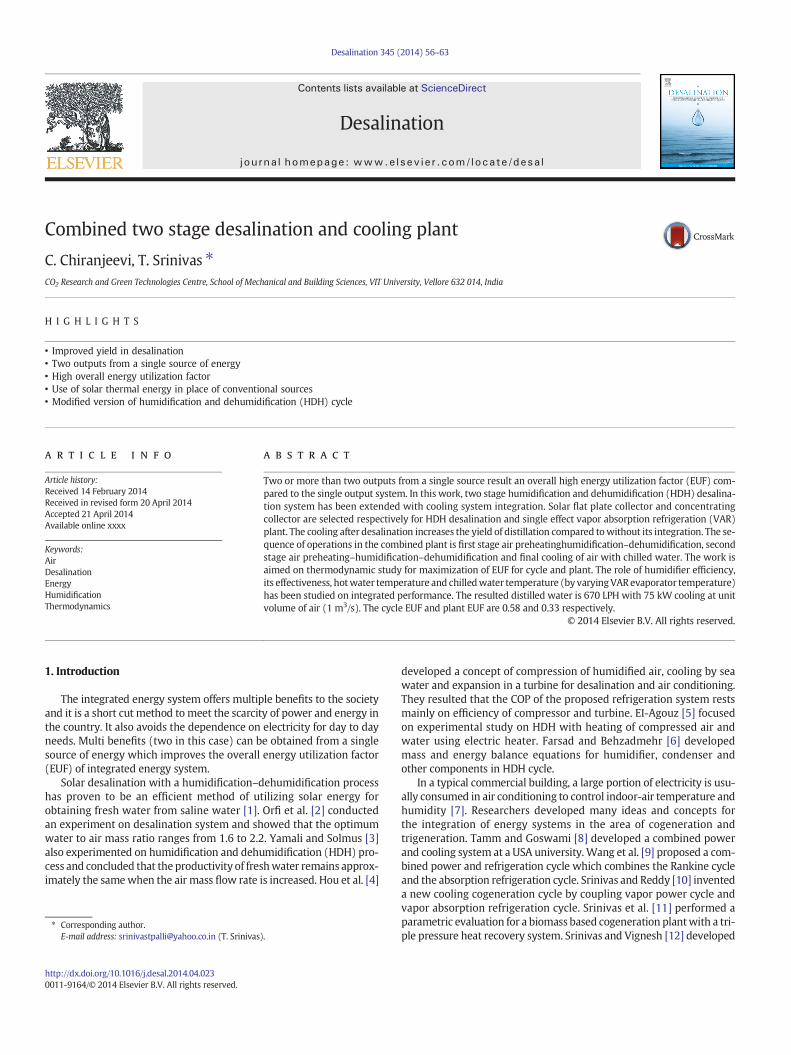
Fig. 1 shows the component's assembly andmaterial flow details forthe proposed two stage desalination and cooling plant. The nodal stateproperties are tabulated in Table 1 for the material flow diagramshown in Fig. 1. This study is only a thermodynamic analysis and fromthe results obtained an experimental setup will be developed. A blowerlocated at the inlet of desalination plant, forces the atmospheric air intothe humidifier via an air preheater (2–3). The temperature of air in airpreheater is increased with the use of hot water (18) supplied by solarwater heater (SWH). The fills in the first humidifier are wetted by thehot water spray (20) from the SWH. Because the hot water temperatureis more than the air inlet temperature (3), heating and humidificationresults in the humidifier. The water temperature will decrease (21) bylatent heat loss to air. The air picks the moisture that can be adopted(4) depending on heat and mass transfer conditions. After heating andhumidification, the humid air is cooled in air cooled dehumidifier(4–5) for the first stage desalination. The condensed distilled water iscollected in a transparent water receiver or container (6) having ananalyzer at the top. The processes in the first stage desalination are
Fig. 1. Integrated plant for d
repeated in the second stage desalination. For centralized air condition-ing, the air from the last stage humidifier needs cooling by the chilledwater. But complete cooling by chilledwater from the exit of secondhu-midifier (9) to low temperature (11) needs more amount of chilledwater which increases the capacity of cooling plant. So, the humid airis cooled and dehumidified in two stages. First, the humid air can becooled in a conventional heat exchanger (9–10) with air or circulatingcooling water and in the second by the chilled water (10–11). Thusthe distilled water is generated in two stages (6 and 12) and the total(15) is collected and taped in a second container. The rest of the cooledair is used for centralized air conditioning (13–14). The chilled water(27) is generated in a vapor absorption refrigeration (VAR) systemusing solar energy. VAR chillers are used for the final stage dehumidifi-cation of air (10–11).
The considered VAR plant is a single effect system having ammonia–water mixture as a working fluid (Fig. 2). The resulted separatortemperature in cooling plant is approximately 115 °C. Therefore solarconcentrating collectors have been selected as a source of heat for theVAR plant. An engine exhaust can also be used partially or fully forVAR operation. The cooled air at a low specific humidity enters theroom (13) and its temperature will increase depending on heat gainfrom surroundings. The heated air at room (14) can be mixed andrecycled in closed cycle or fresh air will be used in open cycle. Thebeam radiation will focus on a focal line in cylindrical parabolic concen-trating collector or on a fixed focus point in case of Scheffler reflector toincrease the temperature of heat transfer fluid (HTF) (29). The HTF isglycol–water. The Scheffler collector is a fixed focus type solar concen-trator with two axis tracking used to generate HTF at 150 °C to 200 °C.The available area of each concentrator is 11 m2 to 16 m2. They can beassembled as per the required area and temperature for the plant. Asolar flat plate collector is used to generate the hot water and storedat daily storage tank which can be used for humidification of air. Theoutlet condition of air depends upon the temperature of water sprayin the air washer. Hence, by properly controlling thewater temperature,
esalination and cooling.
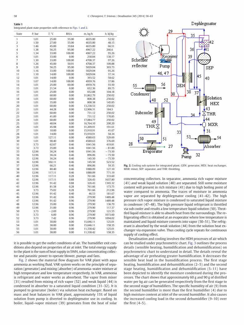
Table 1Integrated plant state properties with reference to Figs. 1 and 2.
State P, bar T, °C RH/x m, kg/h h, kJ/kg
1 1.01 25.00 55.00 4635.00 52.922 1.50 27.00 55.00 4635.00 48.153 1.46 45.00 19.84 4635.00 66.514 1.38 56.25 95.00 4967.22 266.65 1.34 33.00 100.00 4967.22 95.266 1.01 33.00 0.00 258.84 138.177 1.30 33.00 100.00 4708.37 97.268 1.26 45.00 50.91 4708.37 109.889 1.20 56.25 95.00 5029.04 303.7310 1.16 33.00 100.00 5029.04 95.2611 1.10 14.00 100.00 5029.04 37.1412 1.01 14.00 0.00 393.52 58.6213 1.07 14.00 100.00 4959.76 37.8614 1.01 25.00 60.00 4959.76 55.5015 1.01 21.54 0.00 652.36 89.7516 1.01 25.00 0.00 652.88 104.1817 1.01 60.00 0.00 31,862.79 250.0218 1.01 60.00 0.00 808.38 250.0219 1.01 35.00 0.00 808.38 145.8520 1.01 60.00 0.00 13,238.53 250.0221 1.01 44.28 0.00 12,906.31 184.522 1.01 60.00 0.00 731.12 250.0223 1.01 41.00 0.00 731.12 170.8524 1.01 60.00 0.00 17,084.77 250.0225 1.01 48.04 0.00 16,764.10 200.2026 1.01 45.98 0.00 31,209.91 191.6127 1.01 10.00 0.00 15,910.91 41.6728 1.01 14.00 0.00 15,910.91 58.3429 1.01 127.11 0.00 4580.63 529.6930 1.01 90.40 0.00 4580.63 376.6931 3.73 62.67 0.46 1041.56 419.8132 3.73 35.00 0.46 1041.56 −81.8033 12.96 36.24 0.46 1041.56 −75.5034 12.96 36.24 0.46 896.06 −75.5035 12.96 36.24 0.46 145.50 −75.5036 12.96 102.11 0.46 145.50 523.5237 12.96 66.21 0.46 896.06 59.3538 12.96 80.40 0.46 1088.09 127.1039 12.96 117.11 0.46 1088.09 771.1940 12.96 117.11 0.28 761.66 333.6041 12.96 117.11 0.88 326.43 1637.8042 12.96 91.42 0.88 326.43 1365.3243 12.96 81.58 0.28 761.66 173.7544 3.73 75.02 0.28 761.66 212.9645 12.96 91.42 0.40 46.53 181.6746 12.96 91.42 0.96 279.90 1489.4847 12.96 91.42 0.96 279.90 1489.4848 12.96 35.00 0.96 279.90 136.7949 12.96 31.00 0.96 279.90 117.3750 3.73 −2.69 0.96 279.90 121.5551 3.73 6.00 0.96 279.90 1073.6052 3.73 7.42 0.96 279.90 1094.0253 1.01 30.00 0.00 15,646.11 125.0154 1.01 38.00 0.00 15,646.11 158.3555 1.01 30.00 0.00 11,338.42 125.0156 1.01 38.00 0.00 11,338.42 158.35
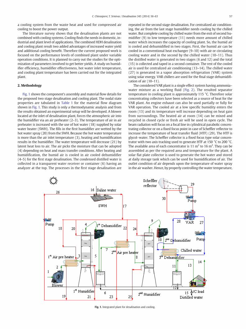
Fig. 2. Cooling sub system for integrated plant; GEN: generator, HEX: heat exchanger,MXR: mixer, SEP: separator, and THR: throttling.
58 C. Chiranjeevi, T. Srinivas / Desalination 345 (2014) 56–63
it is possible to get the outlet conditions of air. The humidifier exit con-ditions also depend on properties of air at inlet. The total energy supplyto the plant is the sumof heat supply in SWH, solar concentrating collec-tor and parasitic power to operate blower, pumps and fans.
Fig. 2 shows the material flow diagram for VAR plant with aquaammonia as working fluid. VAR system works on the principle of sepa-ration (generator) andmixing (absorber) of ammonia–watermixture athigh temperature and low temperature respectively. In VAR, ammoniais refrigerant and water works as absorbent. The vapor from mixer(31) resulted from mixing of rich vapor (52) and weak liquid (44) iscondensed in absorber to a saturated liquid condition (31–32). It ispumped to generator (boiler) via solution heat exchanger. Based onmass and heat balances in VAR plant, approximately 15% of liquidsolution from pump is diverted to dephlegmator use in cooling. Inboiler, liquid–vapor mixture (39) generates from the heat of solar
concentrating collectors. In separator, ammonia rich vapor mixture(41) and weak liquid solution (40) are separated. Still some moisturecontent will present in rich mixture (41) due to high boiling point ofwater compared to ammonia. The traces of moisture in ammoniavapor are separated by dephlegmator cooling (41–42). The highpressure rich vapor mixture is condensed to saturated liquid mixturein condenser (47–48). The high pressure liquid refrigerant is throttledvia sub cooler and results a low temperature liquid solution (50). Throt-tled liquidmixture is able to absorb heat from the surroundings. The re-frigerating effect is obtained at an evaporator where low temperature ismaintained and liquid mixture converts into vapor (50–51). The refrig-erant is absorbed by the weak solution (44) from the solution heat ex-changer via expansion valve. Thus cooling cycle repeats for continuoussupply of cooling effect.
Desalination and cooling involves the HDH processes of air whichcan be studied under psychrometric chart. Fig. 3 outlines the processdetails (sensible heating, humidification and dehumidification) onpsychrometric chart to understand in detail. The details reveal theadvantage of air preheating greater humidification. It decreases thesensible heat load in the humidification process. The first stageheating, humidification and dehumidification (2–5) and the secondstage heating, humidification and dehumidification (5–11) havebeen depicted to identify the moisture condensed during the pro-cesses. The chart shows that approximately 60 g and 90 g of distilledwater per kg air can be generated respectively from the first stage tothe second stage of humidifiers. The specific humidity of air (9) fromthe second humidifier is more than the first humidifier (4) due tohigh moisture content at inlet of the second humidifier. It also causesthe increased cooling load in the second dehumidifier (9–10) overthe first (4–5).
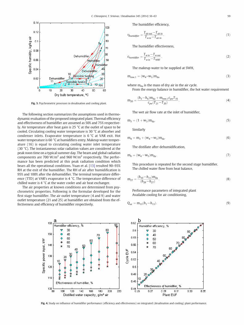
Fig. 3. Psychrometric processes in desalination and cooling plant.
59C. Chiranjeevi, T. Srinivas / Desalination 345 (2014) 56–63
The following section summarizes the assumptions used in thermo-dynamic evaluation of theproposed integrated plant. Thermal efficiencyand effectiveness of humidifier are assumed as 50% and 75% respective-ly. Air temperature after heat gain is 25 °C at the outlet of space to becooled. Circulating cooling water temperature is 30 °C at absorber andcondenser inlets. Evaporator temperature is 6 °C at VAR exit. Hotwater temperature is 60 °C at humidifiers entry.Makeupwater temper-ature (16) is equal to circulating cooling water inlet temperature(30 °C). The instantaneous solar radiation values are considered at thepeak noon time on a typical summer day. The beamand global radiationcomponents are 700 W/m2 and 960 W/m2 respectively. The perfor-mance has been predicted at this peak radiation condition whichbears all the operational conditions. Yuan et al. [13] resulted 90–93%RH at the exit of the humidifier. The RH of air after humidification is95% and 100% after the dehumidifier. The terminal temperature differ-ence (TTD) at VAR's evaporator is 4 °C. The temperature difference ofchilled water is 4 °C at the water cooler and air heat exchanger.
The air properties at known conditions are determined from psy-chrometric properties. Following is the formulae developed for thefirst stage humidifier. The air outlet temperature (4 and 9) and wateroutlet temperature (21 and 25) at humidifier are obtained from the ef-fectiveness and efficiency of humidifier respectively.
Fig. 4. Study on influence of humidifier performance (efficiency and effect
The humidifier efficiency,
ηhumidifier ¼Tair out−Tair in
Tw in−Tair in: ð1Þ
The humidifier effectiveness,
εhumidifier ¼Tw in−Twout
Tw in−TWBT: ð2Þ
The makeup water to be supplied at SWH,
mmw;1 ¼ w4–w3ð Þmda ð3Þ
where mda is the mass of dry air in the air cycle.From the energy balance in humidifier, the hot water requirement
m20 ¼ h3−h4ð Þmda þmmw;1cpwT16
cpw T21−T20ð Þ : ð4Þ
The wet air flow rate at the inlet of humidifier,
m3 ¼ 1þw3ð Þmda: ð5Þ
Similarly
m4 ¼ m3 þ w4−w3ð Þmda: ð6Þ
The distillate after dehumidification,
m6 ¼ w4−w5ð Þmda: ð7Þ
This procedure is repeated for the second stage humidifier.The chilled water flow from heat balance,
m27 ¼ h10−h11ð Þmda
h28−h27ð Þ : ð8Þ
Performance parameters of integrated plantAvailable cooling for air conditioning,
Qac ¼ m13 h1−h13ð Þ: ð9Þ
iveness) on integrated (desalination and cooling) plant performance.
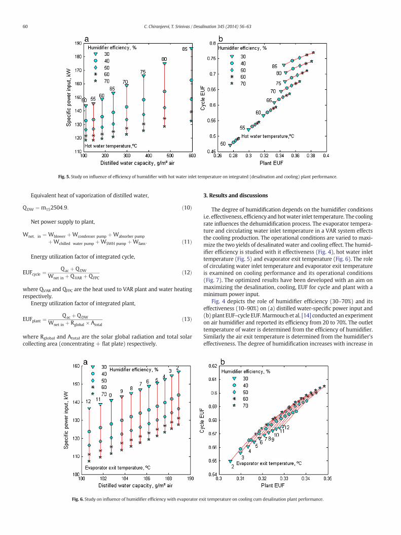
Fig. 5. Study on influence of efficiency of humidifier with hot water inlet temperature on integrated (desalination and cooling) plant performance.
60 C. Chiranjeevi, T. Srinivas / Desalination 345 (2014) 56–63
Equivalent heat of vaporization of distilled water,
QDW ¼ m152504:9: ð10Þ
Net power supply to plant,
Wnet; in ¼ Wblower þWcondenser pump þWabsorber pump
þWchilled water pump þWSWH pump þWfans: ð11Þ
Energy utilization factor of integrated cycle,
EUFcycle ¼Qac þ QDW
Wnet in þ QVAR þ QFPCð12Þ
where QVAR and QFPC are the heat used to VAR plant and water heatingrespectively.
Energy utilization factor of integrated plant,
EUFplant ¼Qac þ QDW
Wnet in þ Rglobal � Atotalð13Þ
where Rglobal and Atotal are the solar global radiation and total solarcollecting area (concentrating + flat plate) respectively.
Fig. 6. Study on influence of humidifier efficiency with evaporator ex
3. Results and discussions
The degree of humidification depends on the humidifier conditionsi.e. effectiveness, efficiency and hotwater inlet temperature. The coolingrate influences the dehumidification process. The evaporator tempera-ture and circulating water inlet temperature in a VAR system effectsthe cooling production. The operational conditions are varied to maxi-mize the two yields of desalinated water and cooling effect. The humid-ifier efficiency is studied with it effectiveness (Fig. 4), hot water inlettemperature (Fig. 5) and evaporator exit temperature (Fig. 6). The roleof circulating water inlet temperature and evaporator exit temperatureis examined on cooling performance and its operational conditions(Fig. 7). The optimized results have been developed with an aim onmaximizing the desalination, cooling, EUF for cycle and plant with aminimum power input.
Fig. 4 depicts the role of humidifier efficiency (30–70%) and itseffectiveness (10–90%) on (a) distilled water-specific power input and(b) plant EUF–cycle EUF.Marmouch et al. [14] conducted an experimenton air humidifier and reported its efficiency from 20 to 70%. The outlettemperature of water is determined from the efficiency of humidifier.Similarly the air exit temperature is determined from the humidifier'seffectiveness. The degree of humidification increases with increase in
it temperature on cooling cum desalination plant performance.
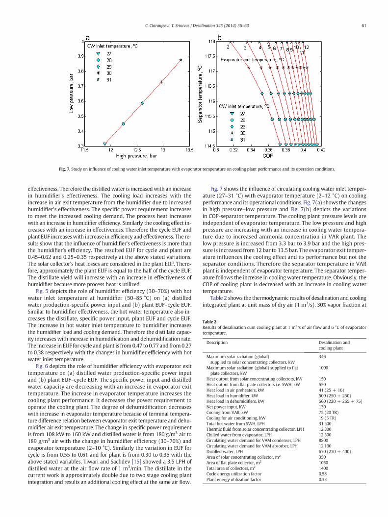
Fig. 7. Study on influence of cooling water inlet temperature with evaporator temperature on cooling plant performance and its operation conditions.
Table 2Results of desalination cum cooling plant at 1 m3/s of air flow and 6 °C of evaporatortemperature.
Description Desalination andcooling plant
Maximum solar radiation (global)supplied to solar concentrating collectors, kW
346
Maximum solar radiation (global) supplied to flatplate collectors, kW
1000
Heat output from solar concentrating collectors, kW 150Heat output from flat plate collectors i.e. SWH, kW 550Heat load in air preheaters, kW 41 (25 + 16)Heat load in humidifier, kW 500 (250 + 250)Heat load in dehumidifiers, kW 560 (220 + 265 + 75)Net power input, kW 130Cooling from VAR, kW 75 (20 TR)Cooling for air conditioning, kW 19 (5 TR)Total hot water from SWH, LPH 31,500Thermic fluid from solar concentrating collector, LPH 12,300Chilled water from evaporator, LPH 12,300Circulating water demand for VAM condenser, LPH 8800Circulating water demand for VAM absorber, LPH 12,100Distilled water, LPH 670 (270 + 400)Area of solar concentrating collector, m2 350Area of flat plate collector, m2 1050Total area of collectors, m2 1400Cycle energy utilization factor 0.58Plant energy utilization factor 0.33
61C. Chiranjeevi, T. Srinivas / Desalination 345 (2014) 56–63
effectiveness. Therefore the distilled water is increased with an increasein humidifier's effectiveness. The cooling load increases with theincrease in air exit temperature from the humidifier due to increasedhumidifier's effectiveness. The specific power requirement increasesto meet the increased cooling demand. The process heat increaseswith an increase in humidifier efficiency. Similarly the cooling effect in-creases with an increase in effectiveness. Therefore the cycle EUF andplant EUF increaseswith increase in efficiency and effectiveness. The re-sults show that the influence of humidifier's effectiveness is more thanthe humidifier's efficiency. The resulted EUF for cycle and plant are0.45–0.62 and 0.25–0.35 respectively at the above stated variations.The solar collector's heat losses are considered in the plant EUF. There-fore, approximately the plant EUF is equal to the half of the cycle EUF.The distillate yield will increase with an increase in effectiveness ofhumidifier because more process heat is utilized.
Fig. 5 depicts the role of humidifier efficiency (30–70%) with hotwater inlet temperature at humidifier (50–85 °C) on (a) distilledwater production-specific power input and (b) plant EUF–cycle EUF.Similar to humidifier effectiveness, the hot water temperature also in-creases the distillate, specific power input, plant EUF and cycle EUF.The increase in hot water inlet temperature to humidifier increasesthe humidifier load and cooling demand. Therefore the distillate capac-ity increases with increase in humidification and dehumidification rate.The increase in EUF for cycle andplant is from0.47 to 0.77 and from0.27to 0.38 respectively with the changes in humidifier efficiency with hotwater inlet temperature.
Fig. 6 depicts the role of humidifier efficiency with evaporator exittemperature on (a) distilled water production-specific power inputand (b) plant EUF–cycle EUF. The specific power input and distilledwater capacity are decreasing with an increase in evaporator exittemperature. The increase in evaporator temperature increases thecooling plant performance. It decreases the power requirement tooperate the cooling plant. The degree of dehumidification decreaseswith increase in evaporator temperature because of terminal tempera-ture difference relation between evaporator exit temperature and dehu-midifier air exit temperature. The change in specific power requirementis from 108 kW to 160 kW and distilled water is from 180 g/m3 air to189 g/m3 air with the change in humidifier efficiency (30–70%) andevaporator temperature (2–10 °C). Similarly the variation in EUF forcycle is from 0.55 to 0.61 and for plant is from 0.30 to 0.35 with theabove stated variables. Tiwari and Sachdev [15] showed a 3.5 LPH ofdistilled water at the air flow rate of 1 m3/min. The distillate in thecurrent work is approximately double due to two stage cooling plantintegration and results an additional cooling effect at the same air flow.
Fig. 7 shows the influence of circulating cooling water inlet temper-ature (27–31 °C) with evaporator temperature (2–12 °C) on coolingperformance and its operational conditions. Fig. 7(a) shows the changesin high pressure–low pressure and Fig. 7(b) depicts the variationsin COP-separator temperature. The cooling plant pressure levels areindependent of evaporator temperature. The low pressure and highpressure are increasing with an increase in cooling water tempera-ture due to increased ammonia concentration in VAR plant. Thelow pressure is increased from 3.3 bar to 3.9 bar and the high pres-sure is increased from 12 bar to 13.5 bar. The evaporator exit temper-ature influences the cooling effect and its performance but not theseparator conditions. Therefore the separator temperature in VARplant is independent of evaporator temperature. The separator temper-ature follows the increase in cooling water temperature. Obviously, theCOP of cooling plant is decreased with an increase in cooling watertemperature.
Table 2 shows the thermodynamic results of desalination and coolingintegrated plant at unit mass of dry air (1 m3/s), 30% vapor fraction at
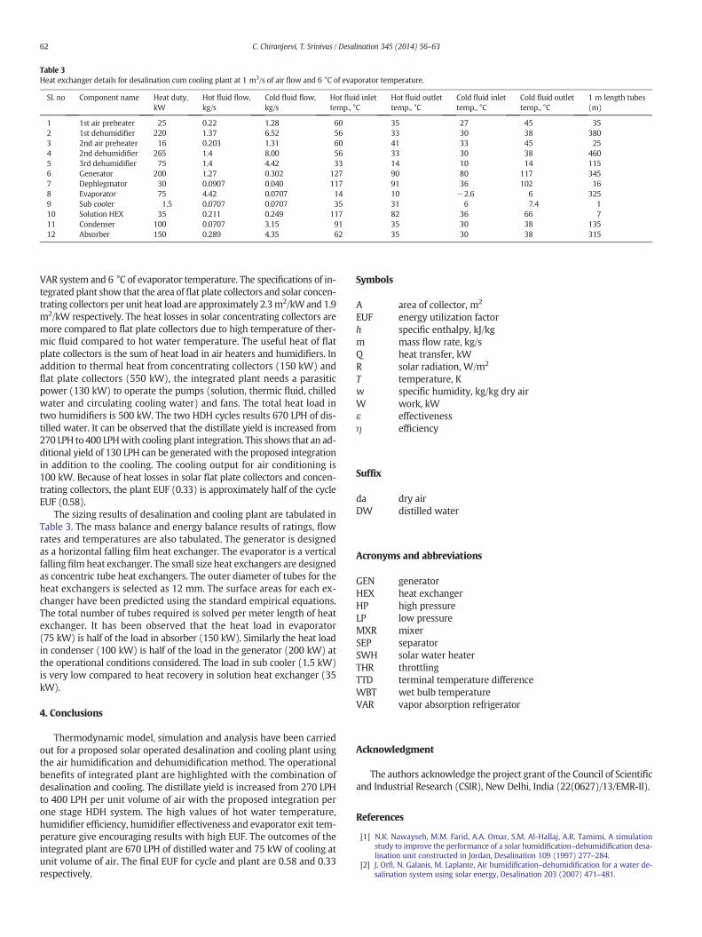
Table 3Heat exchanger details for desalination cum cooling plant at 1 m3/s of air flow and 6 °C of evaporator temperature.
Sl. no Component name Heat duty,kW
Hot fluid flow,kg/s
Cold fluid flow,kg/s
Hot fluid inlettemp., °C
Hot fluid outlettemp., °C
Cold fluid inlettemp., °C
Cold fluid outlettemp., °C
1 m length tubes(m)
1 1st air preheater 25 0.22 1.28 60 35 27 45 352 1st dehumidifier 220 1.37 6.52 56 33 30 38 3803 2nd air preheater 16 0.203 1.31 60 41 33 45 254 2nd dehumidifier 265 1.4 8.00 56 33 30 38 4605 3rd dehumidifier 75 1.4 4.42 33 14 10 14 1156 Generator 200 1.27 0.302 127 90 80 117 3457 Dephlegmator 30 0.0907 0.040 117 91 36 102 168 Evaporator 75 4.42 0.0707 14 10 −2.6 6 3259 Sub cooler 1.5 0.0707 0.0707 35 31 6 7.4 110 Solution HEX 35 0.211 0.249 117 82 36 66 711 Condenser 100 0.0707 3.15 91 35 30 38 13512 Absorber 150 0.289 4.35 62 35 30 38 315
62 C. Chiranjeevi, T. Srinivas / Desalination 345 (2014) 56–63
VAR system and 6 °C of evaporator temperature. The specifications of in-tegrated plant show that the area offlat plate collectors and solar concen-trating collectors per unit heat load are approximately 2.3m2/kWand 1.9m2/kW respectively. The heat losses in solar concentrating collectors aremore compared to flat plate collectors due to high temperature of ther-mic fluid compared to hot water temperature. The useful heat of flatplate collectors is the sum of heat load in air heaters and humidifiers. Inaddition to thermal heat from concentrating collectors (150 kW) andflat plate collectors (550 kW), the integrated plant needs a parasiticpower (130 kW) to operate the pumps (solution, thermic fluid, chilledwater and circulating cooling water) and fans. The total heat load intwo humidifiers is 500 kW. The two HDH cycles results 670 LPH of dis-tilled water. It can be observed that the distillate yield is increased from270 LPH to 400 LPHwith cooling plant integration. This shows that an ad-ditional yield of 130 LPH can be generated with the proposed integrationin addition to the cooling. The cooling output for air conditioning is100 kW. Because of heat losses in solar flat plate collectors and concen-trating collectors, the plant EUF (0.33) is approximately half of the cycleEUF (0.58).
The sizing results of desalination and cooling plant are tabulated inTable 3. The mass balance and energy balance results of ratings, flowrates and temperatures are also tabulated. The generator is designedas a horizontal falling film heat exchanger. The evaporator is a verticalfalling film heat exchanger. The small size heat exchangers are designedas concentric tube heat exchangers. The outer diameter of tubes for theheat exchangers is selected as 12 mm. The surface areas for each ex-changer have been predicted using the standard empirical equations.The total number of tubes required is solved per meter length of heatexchanger. It has been observed that the heat load in evaporator(75 kW) is half of the load in absorber (150 kW). Similarly the heat loadin condenser (100 kW) is half of the load in the generator (200 kW) atthe operational conditions considered. The load in sub cooler (1.5 kW)is very low compared to heat recovery in solution heat exchanger (35kW).
4. Conclusions
Thermodynamic model, simulation and analysis have been carriedout for a proposed solar operated desalination and cooling plant usingthe air humidification and dehumidification method. The operationalbenefits of integrated plant are highlighted with the combination ofdesalination and cooling. The distillate yield is increased from 270 LPHto 400 LPH per unit volume of air with the proposed integration perone stage HDH system. The high values of hot water temperature,humidifier efficiency, humidifier effectiveness and evaporator exit tem-perature give encouraging results with high EUF. The outcomes of theintegrated plant are 670 LPH of distilled water and 75 kW of cooling atunit volume of air. The final EUF for cycle and plant are 0.58 and 0.33respectively.
Symbols
A area of collector, m2
EUF energy utilization factorh specific enthalpy, kJ/kgm mass flow rate, kg/sQ heat transfer, kWR solar radiation, W/m2
T temperature, Kw specific humidity, kg/kg dry airW work, kWε effectivenessη efficiency
Suffix
da dry airDW distilled water
Acronyms and abbreviations
GEN generatorHEX heat exchangerHP high pressureLP low pressureMXR mixerSEP separatorSWH solar water heaterTHR throttlingTTD terminal temperature differenceWBT wet bulb temperatureVAR vapor absorption refrigerator
Acknowledgment
The authors acknowledge the project grant of the Council of Scientificand Industrial Research (CSIR), New Delhi, India (22(0627)/13/EMR-II).
References
[1] N.K. Nawayseh, M.M. Farid, A.A. Omar, S.M. Al-Hallaj, A.R. Tamimi, A simulationstudy to improve the performance of a solar humidification–dehumidification desa-lination unit constructed in Jordan, Desalination 109 (1997) 277–284.
[2] J. Orfi, N. Galanis, M. Laplante, Air humidification–dehumidification for a water de-salination system using solar energy, Desalination 203 (2007) 471–481.

63C. Chiranjeevi, T. Srinivas / Desalination 345 (2014) 56–63
[3] C. Yamali, I. Solmus, A solar desalination system using humidification–dehumidifi-cation process: experimental study and comparison with the theoretical results, De-salination 220 (2008) 538–551.
[4] S. Hou, H. Li, H. Zhang, An open air–vapor compression refrigeration system for airconditioning and desalination on ship, Desalination 222 (2008) 646–655.
[5] S.A. EI-Agouz, A new process of desalination by air passing through seawater basedon humidification–dehumidification process, Energy 35 (2010) 5108–5114.
[6] S. Farsad, A. Behzadmehr, Analysis of a solar desalination unit with humidification–dehumidification using DoE method, Desalination 278 (2011) 70–76.
[7] S.M. Lai, C.W. Hui, Integration of trigeneration system and thermal storage underdemand uncertainties, Appl. Energy 87 (2010) 2868–2880.
[8] G. Tamm, D.Y. Goswami, Novel combined power and cooling thermodynamic cyclefor low temperature heat sources, Part 2: experimental investigation, ASME J. Sol.Energy Eng. 125 (2003) 223–229.
[9] J. Wang, Y. Dai, L. Gao, Parametric analysis and optimization for a combined powerand refrigeration cycle, Appl. Energy 85 (2008) 1071–1085.
[10] T. Srinivas, B.V. Reddy, Thermal optimization of a solar thermal cooling cogenerationplant at low temperature heat recovery, ASME J. Energy Resour. Technol. 136 (2014)1–10.
[11] T. Srinivas, B.V. Reddy, A.V.S.S.K.S. Gupta, Biomass fueled integrated power and re-frigeration system, Proc IME J. Power Energy 225 (2011) 249–258.
[12] T. Srinivas, D. Vignesh, Performance enhancement of GT–ST power plant with inletair cooling using lithium bromide/water vapor absorption refrigeration system, Int.J. Energy Technol. Policy 8 (2012) 94–106.
[13] G. Yuan, Z. Wang, H. Li, X. Li, Experimental study of a solar desalination systembased on humidification–dehumidification process, Desalination 277 (2011) 92–98.
[14] H. Marmouch, J. Orfi, S.B. Nasrallah, Experimental study of the performance of acooling tower used in a solar distiller, Desalination 250 (2010) 456–458.
[15] A. Tiwari, T. Sachdev, Conceptual analysis of desalination systemworking on humid-ify and dehumidify technique using solar air heater, International Conference onMechanical and Robotics Engineering (ICMRE'2012) May 26–27, 2012 Phuket,2012, pp. 73–79.