Embed Size (px)
Citation preview
Energy Vol. 16, No. 10, pp. 12.59-1274, 1991 036&5442/91 $3.00 + 0.00 tinted in Great Britain. All rights reserved Copyright 0 1991 Pergamon Press plc
COMBINING FUEL CELLS WITH FUEL-FIRED POWER PLANTS FOR IMPROVED EXERGY EFFICIENCY
WILLIAM R. DUNBAR and NOAM Lrout Department of Mechanical Engineering and Applied Mechanics, University of Pennsylvania,
Philadelphia, PA 19104-6315, U.S.A.
RICHARD A. GAGGIOLI
Department of Mechanical Engineering, Marquette University, Milwaukee, WI 53233, U.S.A.
(Received 7 May 1990; received for publication 24 April 1991)
Abstract-The thermodynamic advantages of fuel-cell systems are studied to: (i) evaluate the increase in plant exergy efficiency when incorporating fuel-cell units into electrical power generating stations and (ii) identify and discuss their effect on the components of such plant systems. Topping conventional Rankine cycle power plants with a range of commercial fuel cells is shown to increase the exergetic efficiency of the plant by up to 49%, raising that efficiency from the value of 41.5% for the conventional power plant without fuel cells to about 62% for the fuel-cell-topped power plant. This improvement stems primarily from the improved exergetic efficiency of fuel oxidation in these proposed topping power plants, as contrasted with the highly dissipative combustion process in conventional fuel-fired ones.
INTRODUCTION
Past literature has revealed the combustion process as a prime target for seeking improvements to existing, low energy-conversion efficiencies. With present technology, the conventional fuel oxidation via the highly irreversible combustion process consumes about 30% of the usable fuel energy. The reduction of such irreversibilities would obviously improve the efficiency of electricity production.
Fuel cells convert chemical energy of fuel directly into electricity. When fuel cells produce the entire electrical power output, the oft-cited apparent advantage is elimination of the Camot-efficiency limitation. This fact and environmental advantages explain the increasing interest in fuel-cell systems for power generation.‘** However, the fundamental thermodynamic reason for interest in fuel cells is the reduction of combustion irreversibility.%’
Although fuel-cell technology has been studied extensively, the best ways to employ fuel-cell units for the generation of electrical power remain to be determined. A number of fuel-cell/power-plant configurations are possible for that purpose. One possible configuration, proposed here, is the utilization of a fuel cell as a topping unit to an existing or future conventional power plant. In this configuration, hot fuel and oxidant would first be passed through the fuel cell which would thus produce part of the overall electrical output of the plant. After the gases emerge from the fuel cells, still at relatively high temperature, they would be mixed and oxidation would be completed by combustion; the products would be used to generate steam for powering a Rankine cycle plant which produces the remainder of the electrical energy. As will be demonstrated, compared to a conventional power plant this scheme reduces the overall oxidation irreversibility and it also avoids the prohibitive capital costs associated with complete oxidation in cells. The objective of this work is to examine the exergetic advantages of such systems theoretically.
THERMODYNAMIC CONSIDERATIONS
The theoretical advantages of fuel-cell operation can be explained in both microscopic and macroscopic terms. From a microscopic point of view, an integral part of chemical reactions is a
tTo whom all correspondence should be addressed. 1259
1260 WILLIAM R. DUNBAR et al
repositioning of the associated electrons. With fuel cells, this repositioning is achieved with greater control than in combustion. In the process, a portion of the electro-chemical energy of electron bonding is extracted electrically rather than being totally dissipated into thermal energy (random motion of the reaction components) as in combustion. Thus, there is less associated entropy production than in ordinary combustion, where electronic energy is not exploited and the amount of entropy production is left unconstrained.
Macroscopically speaking, to reduce entropy production for a fixed process rate, one must either increase the local temperature or reduce the relevant thermodynamic driving force(s), inasmuch as376s*9
& = (l/T)R[driving force(s)], (1)
where T is the absolute temperature and R the process rate. In turn, the rate of useful energy destruction is directly proportional to the entropy production rate3P6
& = l&.
By reducing process irreversibilities, device and system efficiencies are improved.
(2)
Combustion irreversibility In ordinary combustion, a fuel is brought in direct contact with oxygen to react and produce
oxidation products. The result is a conversion of chemical energy of the fuel to thermal energy of the products.” The amount of exergy consumption is quite large, of the order of 20-30% of the fuel exergy. The results of Ref. 10 disclosed that approximately 80% of the combustion irreversibility occurs during the internal thermal energy exchange subprocess. The objective of this study is to find ways for reducing the irreversibility associated with the fuel oxidation and the internal thermal energy exchange subprocesses, thus improving electrical power-generation efficiency.
Fuel oxidation irreversibility When a fuel is burned in air at the rate Rf, the driving force for the reaction is the difference
between the chemical potentials (p) of the reactants and products, which is the chemical affinity (A) of the reaction. The rate of useful power consumption by fuel oxidation is6*8*9
& = G& = T,&(AIT) = ToR&,,, + poxygen - ~~rodu&lT. (3)
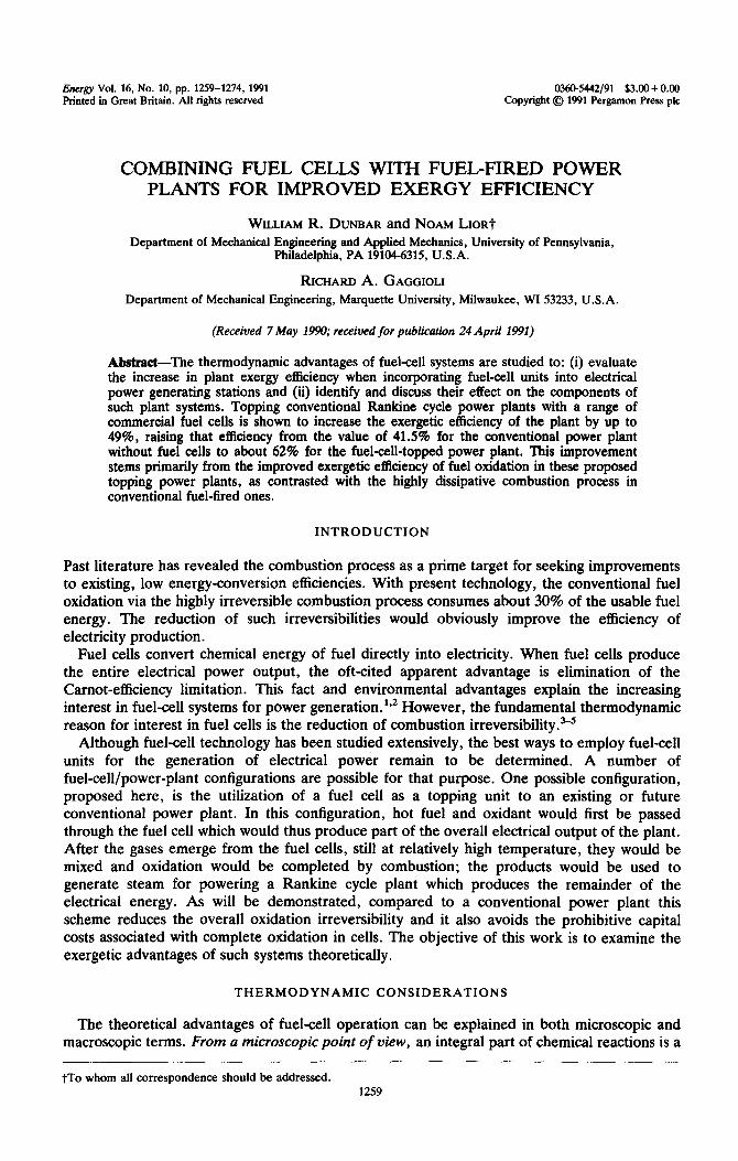
Fuel cells lower the reaction affinity by first passing ions through an electrolyte. For example, solid oxide fuel cells operate with oxygen migrating through a solid electrolyte (cf. Fig. 1). By passing oxygen through the solid electrolyte prior to fuel oxidation, such a fuel cell lowers
Y oxygen which, in turn, lowers the power consumption of the oxidation reaction [Eq. (3)], i.e.,
Fuel c
(Hz, $0) Products
Electrolyte Voltage
Cathode
Air
---I-
Air 2 (Air)d
t
VW,
I 1
Fig. 1. Chemically-reacting system within a solid-oxide fuel cell.
Combining fuel cells with fuel-fired power plants 1261
the electrochemical potential of oxygen at the anode (where the oxidation occurs) is lower than the value sensed in ordinary combustion, namely the value in the air free stream on the cathode side of the electrolyte.
Upon going through the electrolyte and dropping in potential, the oxygen ions yield electrons at a higher potential (at the anode) than the potential at which they were acquired (at the cathode). The cell thus delivers net power, electrically. Therefore, after passing oxygen through the electrolyte, the fuel oxidation is less violent (less dissipative, less irreversible) inasmuch as the force driving the reaction L is reduced.
Internal thermal energy exchange irreversibility The rate of useful power consumption by heat transfer is6,8*9
& = -(T,/T)(e - VT/T), (4)
where E is the thermal energy flux. By extracting electrical energy during the overall reaction, the energy of the reaction products is reduced. In turn, the temperature gradient between the reaction zone and the neighboring zones is lower than that sensed in ordinary combustion. Thus, relatively less exergy is destroyed during the internal thermal energy exchange [Eq. (4)].
Boiler combustion irreversibility An additional benefit of fuel-cell topping systems is the reduction of exergy consumption in
subsequent combustion, downstream of the fuel-cell unit in the boiler combustion chamber. This reduction is a consequence of a reduction of the average chemical potentials of oxygen and fuel because they are more dilute after partial oxidation in the fuel cells.
We consider the relationship
@i/T =gi(T, P)/T + R lnxi (5)
for ideal gases.” It can be seen that at a given T, as xi is reduced for reactants and increased for products, their pi/T values are reduced and increased, respectively, with the effect of reducing the value of d/T. So, if part of the fuel oxidation has been accomplished in fuel cells, thereby decreasing the Xi of the fuel and oxygen and increasing the Xi of the products, the value
_-_--_------------------------------------------- I
I I
I -0 I
, I _a I
I I
I I I [_ -
I I I
I I
Fuel-cell , I @ \ *
Preheater , \ 0 I Fuel
I system I \ a--,#2 \
I
I I ‘- o_ I -- +-
0 ’ 3 I
@ @ I
63 I
t tl, I I
I I Combustion @ Power cycle 0
I chamber heat Preheater lo
c #l
I exchanger I To
I I I I sfack L--e-_ ---------------------- ----------------_-_
/
System Yl
‘z’A$L~,~t~~ Ambi!?a~ r ’
t
LmA3nser Fig. 2. The plant configuration of a fuel-cell topping system.
1262 WILLIAM R. DUNBAR et al
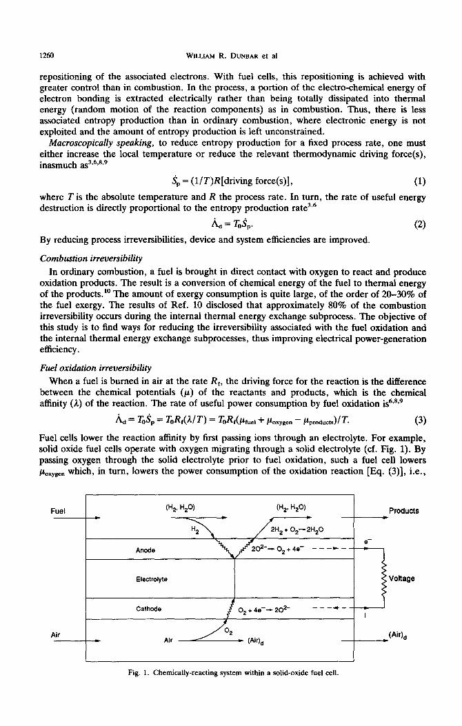
of A/T at the onset of the subsequent combustion in the boiler is lowered. Since A/T goes from the initial value to zero as the combustion proceeds, the effect is then to reduce its average magnitude during combustion and, from Eq. (3), to reduce the exergy destruction. This conclusion is based on the assumption that the temperature of the reactants prior to combustion is essentially the same as in ordinary boiler combustion. It can be seen from the schematic diagram of Fig. 2 that this will be the case, as will be confirmed quantitatively later in the paper.
CASE STUDY
Plant configuration
The plant configuration shown in Fig. 2 serves here to evaluate the thermodynamic advantages of fuel-cell units. Based on the discussion above, this type of configuration reduces the investment in fuel-cells because they are thereby used only while the chemical driving forces are still high. Instead of continuing the oxidation process with increasingly diluted reactants, which produces concomitantly decreasing power yield, the diluted reactants are fed to the combustor, where they combine more efficiently.
It is not implied that this plant configuration is either the most efficient or most economical, but it is a simple example which serves to illustrate the improvement to thermodynamic efficiency when incorporating fuel-cell units into electrical power-generating or cogenerating plants.
This power plant consists of (1) three heat exchangers (preheaters 1, 2, and the power-cycle heat exchanger), (2) a fuel-cell unit, (3) a combustion chamber, and (4) the steam power cycle of an existing 300 MW power plant described in detail in Ref. 7. Hydrogen is fed to preheater 2 at ambient pressure and temperature, to raise its temperature to the level needed for operating the fuel-cell unit. Ambient air is passed through preheaters 1 and 2 for the same purpose.
Partial oxidation of the fuel takes place within the fuel-cell system. Having delivered an amount of electrical power, the product streams (depleted fuel and air) exit the fuel-cell unit at a higher temperature and, following heat exchange in preheater 2, enter the combustion chamber where fuel oxidation is completed. The combustion product gas then supplies heat first to the power cycle and then to the incoming air.
Fuekell unit perjormance characieristics
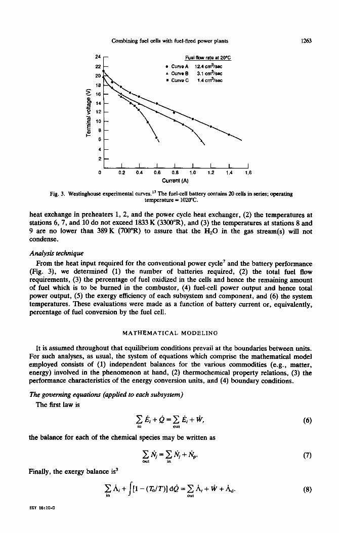
While improvements in solid electrolyte fuel-cells have since been achieved, the fuel-cell performance characteristics in this study are assumed to be those of a Westinghouse Bell-and-Spigot design.13 These performance data are presented in Fig. 3 for an array (battery) of 20 cells, for three values of fuel-flow rate per array. At a given flow rate, based on the stoichiometry of the fuel-cell chemistry, the percentage of fuel oxidized within the cells is proportional to the current; for the three flow rates shown as curves A, B, and C in Fig. 3, 100% fuel conversion is reached at currents of 5, 1.25, and 0.56 A, respectively.
Power cycle performance characteristics
The characteristics of the employed power cycle are those of an existing 300 MW (coal-burning) electrical power plant.’ The thermodynamic state properties of the power cycle are fixed at the values given in Ref. 7 and the exergy values at each location remain thus unchanged for a given reference temperature. Although presently not commercially practical, it was assumed that hydrogen is the power-plant fuel because performance data are availablei and can be simulated4’5 for hydrogen-fuelled fuel cells. Cells operating on natural gas and models for simulating them are under development, but their performance characteristics are not readily available.
Temperature constraints
The following assumptions were made about temperatures and temperature differences needed for heat transfer (cf. Fig. 2): (1) 44.4K (80”R) minimal temperature difference for all
Combining fuel cells with fuel-fired power plants 1263
24 -
22 -
0
Fuelfbw rate at2OoC
l Curve A 12.4cm3/sec
A CUNeB 3.1 cm3/sec
n ClJNeC 1.4 cm%ec
6-
L I I I I I I I I 0 0.2 0.4 0.6 0.6 1.0 1.2 1.4 1.6
Current (A)
Fig. 3. Westinghouse experimental curves. l3 The fuel-cell battery contains 20 ds in series; operating temperature = 1020°C.
heat exchange in preheaters 1, 2, and the power cycle heat exchanger, (2) the temperatures at stations 6, 7, and 10 do not exceed 1833 K (33CWR), and (3) the temperatures at stations 8 and 9 are no lower than 389 K (7OO“R) to assure that the Hz0 in the gas stream(s) will not condense.
Analysis technique From the heat input required for the conventional power cycle7 and the battery performance
(Fig. 3), we determined (1) the number of batteries required, (2) the total fuel flow requirements, (3) the percentage of fuel oxidized in the cells and hence the remaining amount of fuel which is to be burned in the combustor, (4) fuel-cell power output and hence total power output, (5) the exergy efficiency of each subsystem and component, and (6) the system temperatures. These evaluations were made as a function of battery current or, equivalently, percentage of fuel conversion by the fuel cell.
MATHEMATICAL MODELING
It is assumed throughout that equilibrium conditions prevail at the boundaries between units. For such analyses, as usual, the system of equations which comprise the mathematical model employed consists of (1) independent balances for the various commodities (e.g., matter, energy) involved in the phenomenon at hand, (2) thermochemical property relations, (3) the performance characteristics of the energy conversion units, and (4) boundary conditions.
The governing equations (applied to each subsystem)
The first law is
~lZi+Q=Cl?i+tVj in out
the balance for each of the chemical species may be written as
Finally, the exergy balance is3
C~i+f[l-(T,/T)]de=~li,+~+%. in out
(‘3
(7)
(8)
EGY 16:10-O
1264 WILLIAM R. DUNBAR et al
The exergy associated with the entering matter plus the exergy of the net heat addition is seen to be equal to the exergy of the exiting matter plus the useful work output and the irreversible destruction of exergy associated with all real processes.
Thermochemical property relations
To evaluate the enthalpies, we write
where, assuming ideal-gas behavior,
/ij = &, + I
= 2pi dT. (10) To
The entropy is T
ij = ijo + I
&(dT/T) - R ln(q/P,). (11) To
The specific flow exergies are”
where
A drj = amj + ri,,, (12)
I
T . amj = e,[l - (TO/T)] dT + ~T,ln(P/P,), (13)
Ta
&uj = hj(To) - ToJj(To, PO) + fiT0 lnxj - JAY. (14)
The specific flow exergy a^, is thus composed of two contributions; (1) the specific thermo- mechanical exergy iTM and (2) the specific chemical exergy &u. Finally, the total specific/flow exergy of a given flow stream i is
while the total flow exergy of stream i is
iii = ~iji(ifi. (16)
Ideal gas behavior has been assumed for the fuel, air and product gas streams. The properties were obtained from Refs. 11 and 12.
Boundary conditions
The boundary conditions for the power plant are: (1) the incoming fuel and air temperatures are 25°C (2) the stack temperature is fixed at 135°C (to assure that the Hz0 in the stack gas will not condense), (3) ambient reference air temperature is 25°C (77”F), (4) reference environmental water temperature is 10.3”C (50”F), (5) all gas stream pressures are atmos- pheric, (6) all units, except the power-cycle heat exchanger, have adiabatic boundaries, (7) the power cycle heat exchanger heat loss is 13.01 MW (a typical value for modern boilers’), (8) 100% excess (200% theoretical) combustion air, to match the air-fuel ratio corresponding to the fuel-cell data employed, l3 (9) the heat transfer to the power cycle =660.14 MW,’ (10) the amount of heat transfer to the air in preheater 1 is fixed at a value of 117.23 MW (a value which assures that the hot and cold stream temperatures in the cogeneration unit do not cross), and (11) the stipulated fuel-cell inlet fuel and air temperatures =1020°C.‘3
RESULTS
Conventional plant efficiency
The conventional power plant (one without a fuel-cell unit and preheater 2) was reevaluated, with hydrogen substituted as the fuel, and the results of the modified exergy analysis are shown
Combining fuel cells with fuel-tired power plants 1265
Fans, pumps, etc.
Stack A
(Z) (3,
60iler 100
. -24.7 combustion - 50.5 Turbines 44.2 Generator
c c (100) -22.4 heat transfer (“.O)
-4.2 (43.0) -0.7
-0
(1.9)
Condensers 2, and heaters &
(48.0)
41.5 (40.4)
7 System output
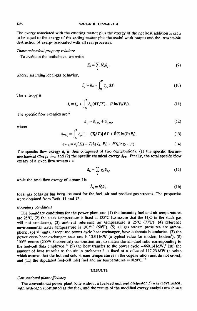
Fig. 4. Exergy and (energy) flow diagrams for a typical power-plant configuration.
in Fig. 4 and Table 1. In Fig. 4, the numbers shown in parentheses are exergy values as a percentage of the total fuel input exergy. Similar to past second-law studies of power plant performance,’ these results reveal that the combustion process is the most inefficient operation, accounting for nearly half the total exergy destruction in the power plant.
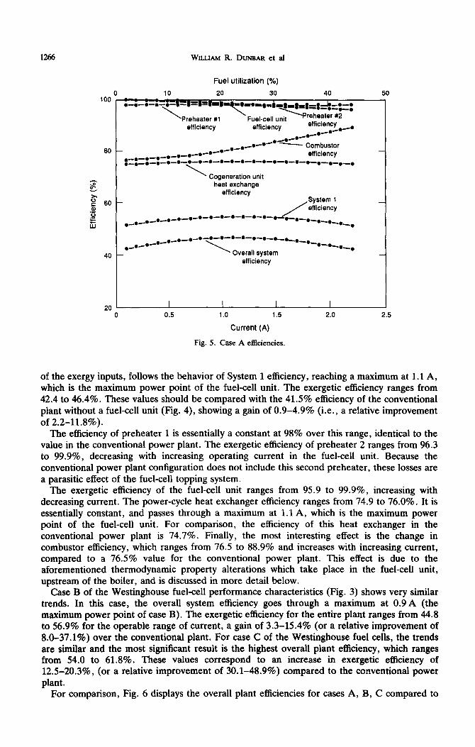
Plant and unit efficiency for the fuelcell topping systems Figure 5 contains the results of system and component exergetic efficiencies as a function of
current for case A of the Westinghouse experimental data (12.4cm3/sec of fuel to each 20-cell battery, Fig. 3). System 1, by definition, is the gas side of the plant (including the boiler entrance and exit conditions of the Hz0 in the power cycle). The overall system efficiency, defined (as are all efficiencies in this work) as the ratio of all of the useful exergy outputs to all
Exergy (Input)~[Output]
Table 1. Exergy analysis for a 300 MW power plant (typical configuration).
z;gy
MW
Losses as Losses as % of % of
System Input System Total Exergy Losses
System Input (ambient Hz and air)
(706.9)
system Output
Boiler
a. Combustion
b. Heat Transfer
c. Stack Losses
Turbines
Generator
[293.5]
(567.21
[356.8]
[312.91
[307.9]
Feedwater Heaters
Fans, Pumps, etc. ( 14.4)
413.4 58.5 100.0
174.5 24.7 42.2
158.3 22.4 38.3
17.3 2.4 4.1
29.5 4.2 7.2
5.0 0.7 1.2
11.5 1.6 2.7
6.5 0.9 1.5
14.4 2.0 3.4
Device Efficiency
41.5
76.5
74.8
88.2
98.4
1266 WILLIAM R. DUNBAR et al
Fuel utilization (%)
20 30
80 ,_e-.-o-*-e
-e-.-+-e efficiency ,_e_e_e_e-e-o-e-e-.-o-e-e-o-e-e-e-e-e-e-.
\ ’ Cogeneration unit
heat exchange efficiency
40
20 0 0.5
_e-eceC- Combustor
System 1 /efficiency
.-.-.-*-e-o_._._._._._. Overall system
efficiency
1.0 1.5
Current (A)
Fig. 5. Case A efficiencies.
2.0 2.5
of the exergy inputs, follows the behavior of System 1 efficiency, reaching a maximum at 1.1 A, which is the maximum power point of the fuel-cell unit. The exergetic efficiency ranges from 42.4 to 46.4%. These values should be compared with the 41.5% efficiency of the conventional plant without a fuel-cell unit (Fig. 4), showing a gain of 0.9-4.9% (i.e., a relative improvement of 2.2-11.8%).
The efficiency of preheater 1 is essentially a constant at 98% over this range, identical to the value in the conventional power plant. The exergetic efficiency of preheater 2 ranges from 96.3 to 99.9%, decreasing with increasing operating current in the fuel-cell unit. Because the conventional power plant configuration does not include this second preheater, these losses are a parasitic effect of the fuel-cell topping system.
The exergetic efficiency of the fuel-cell unit ranges from 95.9 to 99.9%, increasing with decreasing current. The power-cycle heat exchanger efficiency ranges from 74.9 to 76.0%. It is essentially constant, and passes through a maximum at 1.1 A, which is the maximum power point of the fuel-cell unit. For comparison, the efficiency of this heat exchanger in the conventional power plant is 74.7%. Finally, the most interesting effect is the change in combustor efficiency, which ranges from 76.5 to 88.9% and increases with increasing current, compared to a 76.5% value for the conventional power plant. This effect is due to the aforementioned thermodynamic property alterations which take place in the fuel-cell unit, upstream of the boiler, and is discussed in more detail below.
Case B of the Westinghouse fuel-cell performance characteristics (Fig. 3) shows very similar trends. In this case, the overall system efficiency goes through a maximum at 0.9 A (the maximum power point of case B). The exergetic efficiency for the entire plant ranges from 44.8 to 56.9% for the operable range of current, a gain of 3.3-15.4% (or a relative improvement of 8.0-37.1%) over the conventional plant. For case C of the Westinghouse fuel cells, the trends are similar and the most significant result is the highest overall plant efficiency, which ranges from 54.0 to 61.8%. These values correspond to an increase in exergetic efficiency of 12.5-20.3%, (or a relative improvement of 30.1-48.9%) compared to the conventional power plant.
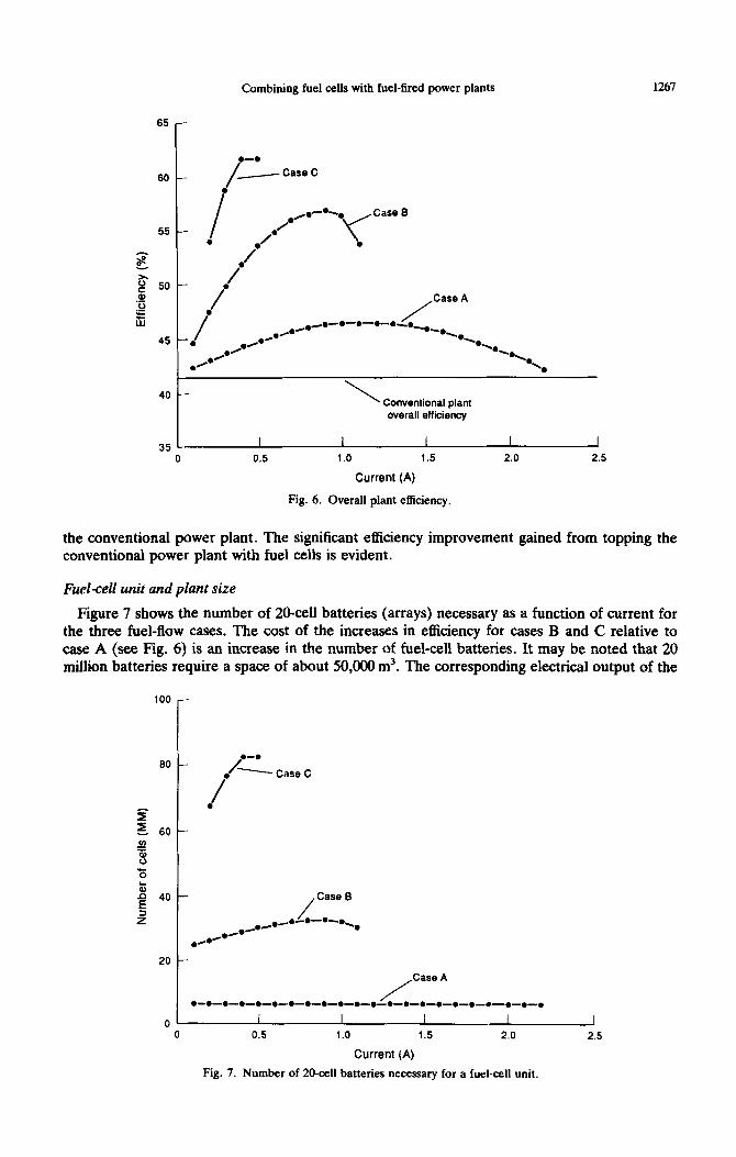
For comparison, Fig. 6 displays the overall plant efficiencies for cases A, B, C compared to
Combining fuel cells with fuel-tied power plants 1267
65 -
0-O
40 - \ Conventional plant overall efficiency
35 I I I I - I
0 0.5 1.0 1.5 2.0 2.5
Current (A)
Fig. 6. Overall plant efficiency.
the conventional power plant. The significant efficiency improvement gained from topping the conventional power plant with fuel cells is evident.
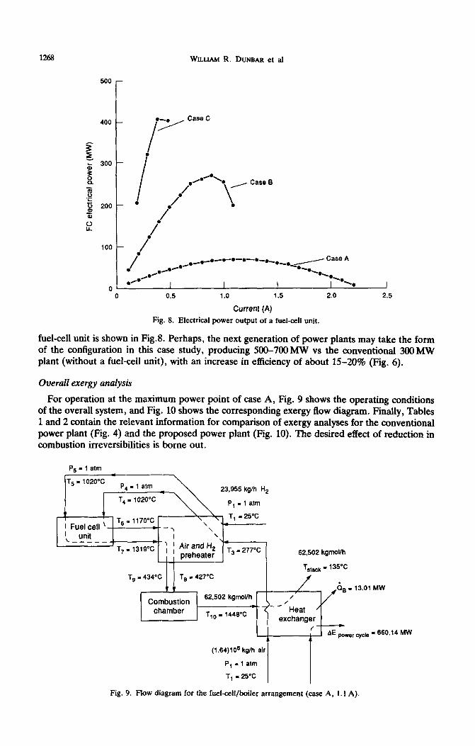
Fuelcell unit and plant size
Figure 7 shows the number of 20-cell batteries (arrays) necessary as a function of current for the three fuel-flow cases. The cost of the increases in efficiency for cases B and C relative to case A (see Fig. 6) is an increase in the number of fuel-cell batteries. It may be noted that 20 million batteries require a space of about 50,OtXl m3. The corresponding electrical output of the
100
60
t
.-. / . - CasaC
/
f .
E. 60
/
Case A
l _~_~_~_~_~_._.~.-.~.-o-~-o-o-o-~-o-~-~-.-.
01 I I I I I 0 0.5 1.0 1.5 2.0 2.5
Current (A)
Fig. 7. Number of 20-cell batteries necessary for a fuel-cell unit.
1268 WILLIAM R. DUNBAR et al
500 -
l 7 Case = z 4oo- I . : 300 -
s i% 3 .g I /’
.-•\ l , Case 0
r, 200 - / \ .
a,
i
l /’
/
‘00 - /
/
Case A ,e+
*,0-.-*-o-.-.,*_* /
l .gfl l / OH’ -02.
-..a l R
0 I I I -0
I %*
0 0.5 1.0 1.5 2.0
Current (A)
I
2.5
Fig. 8. Electrical power output of a fuel-cell unit.
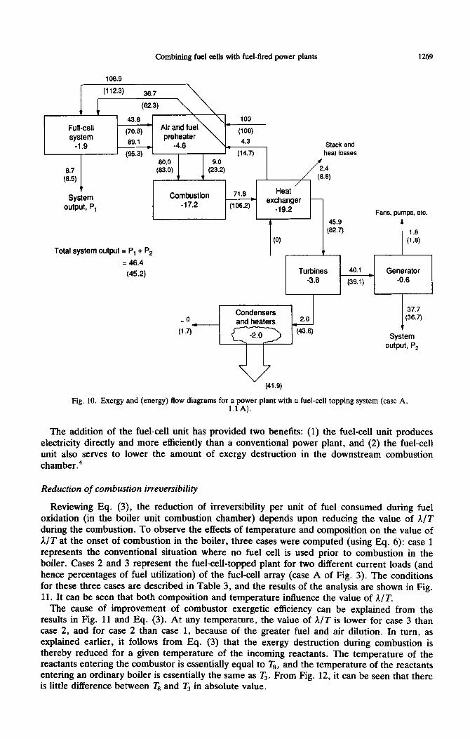
fuel-cell unit is shown in Fig.8. Perhaps, the next generation of power plants may take the form of the configuration in this case study, producing 500-700MW vs the conventional 3OOMw plant (without a fuel-cell unit), with an increase in efficiency of about 15-20% (Fig. 6).
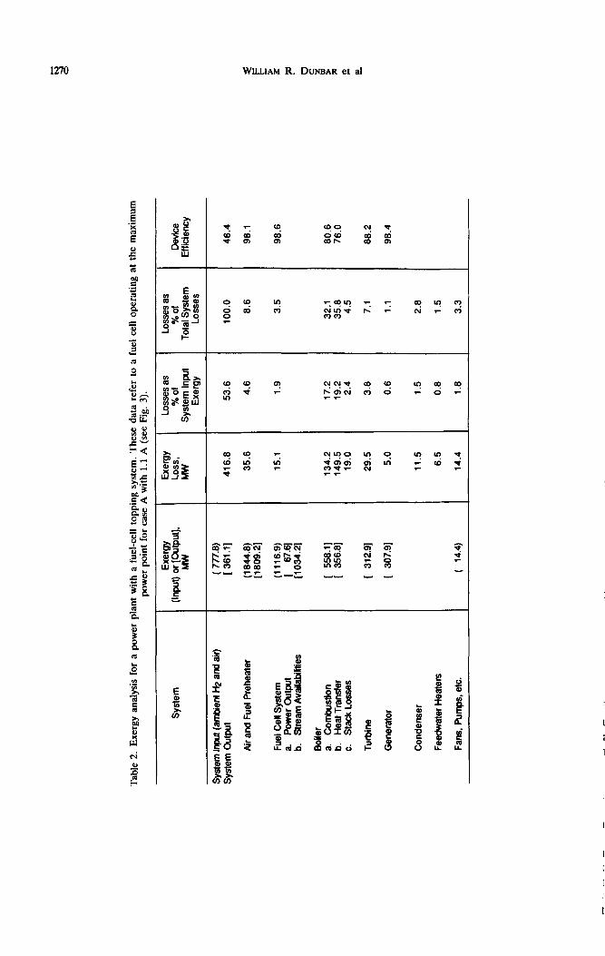
Overall exergy analysis
For operation at the maximum power point of case A, Fig. 9 shows the operating conditions of the overall system, and Fig. 10 shows the corresponding exergy flow diagram. Finally, Tables 1 and 2 contain the relevant information for comparison of exergy analyses for the conventional power plant (Fig. 4) and the proposed power plant (Fig. 10). The desired effect of reduction in combustion irreversibilities is borne out.
P, = 1 atm
P, - 1 atm
T4 I 1020°C
1 Fuel cell ‘-- T, = 1170°C
*- - , \ ‘4
\ ~ _ u_nit I \
--- ’
14 T,- 1319% , , I AirandH,
preheater T3 I 277°C 62,502 kgmollh
T s,a& = 1 WC
T, I 434°C T, = 427°C *
1v QB I 13.01 MW
Combustion 62,502 kgmollh
chamber T,, = 1440°C exchanger
I , IL
AE Ewe, +,, - 660.14 MW
(1.64)10e kg/h air
P, - 1 atm
T, I 25°C
Fig. 9. Flow diagram for the fuel-cell/boiler arrangement (case A, 1.1 A).
Combining fuel cells with fuel-fired power plants
106.9
1269
100 *
(100)
4.3 * Stack and
(14.7) heat losses
(E) I System
Combustion 71.6 Heat c -
output, P, -17.2 (106.2) exchanger
-19.2 Fans, pumps, etc.
A 45.9 A
(62.7) 1.6
(0) (1.6)
Total system output = P, + P, v _ = 46.4
(45.2) Turbines 40.1 Generator -3.8 (39.1) -0.6
1 1
I 37.7 (36.7)
System output, P,
Fig. 10. Exergy and (energy) flow diagrams for a power plant with a fuel-cell topping system (case A, 1.1 A).
The addition of the fuel-cell unit has provided two benefits: (1) the fuel-cell unit produces electricity directly and more efficiently than a conventional power plant, and (2) the fuel-cell unit also serves to lower the amount of exergy destruction in the downstream combustion chamber.4
Reduction of combustion irreversibility
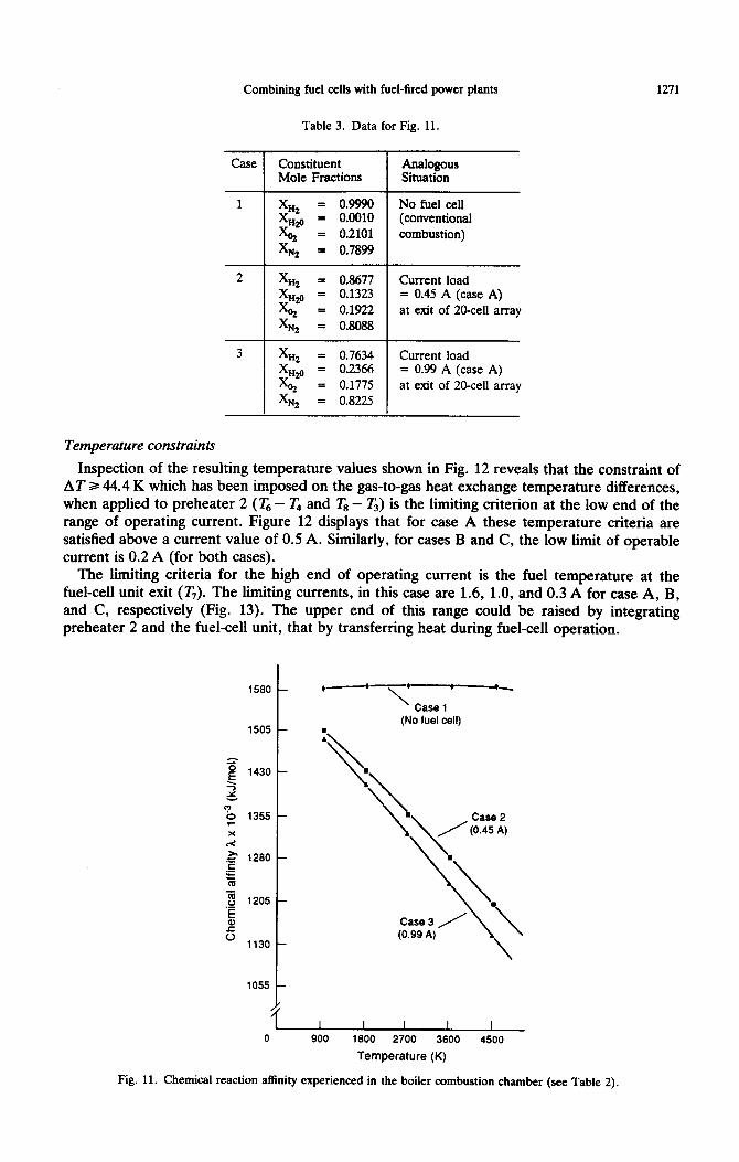
Reviewing Eq. (3), the reduction of irreversibility per unit of fuel consumed during fuel oxidation (in the boiler unit combustion chamber) depends upon reducing the value of A/T during the combustion. To observe the effects of temperature and composition on the value of A/T at the onset of combustion in the boiler, three cases were computed (using Eq. 6): case 1 represents the conventional situation where no fuel cell is used prior to combustion in the boiler. Cases 2 and 3 represent the fuel-cell-topped plant for two different current loads (and hence percentages of fuel utilization) of the fuel-cell array (case A of Fig. 3). The conditions for these three cases are described in Table 3, and the results of the analysis are shown in Fig. 11. It can be seen that both composition and temperature influence the value of A/T.
The cause of improvement of combustor exergetic efficiency can be explained from the results in Fig. 11 and Eq. (3). At any temperature, the value of A/T is lower for case 3 than case 2, and for case 2 than case 1, because of the greater fuel and air dilution. In turn, as explained earlier, it follows from Eq. (3) that the exergy destruction during combustion is thereby reduced for a given temperature of the incoming reactants. The temperature of the reactants entering the combustor is essentially equal to T,, and the temperature of the reactants entering an ordinary boiler is essentially the same as T3. From Fig. 12, it can be seen that there is little difference between Ts and T3 in absolute value.
Tab
le
2.
Exe
rgy
anal
ysis
for
a p
ower
pla
nt w
ith a
fue
l-ce
ll to
ppin
g sy
stem
. T
hese
da
ta r
efer
to
a fu
el c
ell
oper
atin
g at
the
max
imum
po
wer
poi
nt f
or c
ase
A
with
1.1
A (
see
Fig
. 3)
.
Sys
tem
Sys
tem
hpu
t (a
mbi
ent
Ii2 a
nd a
ir)
Sys
tem
O
utpu
t
Air
and
Fue
l P
rehe
ater
Fue
l Cel
l S
yste
m
a.
Pow
er
Cut
put
b S
trea
m A
vaik
bilil
ies
But
ler
a.
Com
bust
ion
b.
Hea
t T
rans
ter
c.
stac
k Lo
sses
Tur
bine
Con
dens
er
Fee
dwat
er
Hea
ters
Fan
s, P
umps
, et
c.
Exe
rgy
WW
) or
&xJ
p”‘*
( 77
7.8)
[
361
.l]
(184
4.8)
[1
809.
2]
‘r’ 1
y;.Q
;
[103
4.2]
[ 31
2.91
[ 30
7.91
( 14
.4)
Ew
u Lo
ss,
MN
416.
8 53
.6
35.6
4.
6
15.1
1
.Q
100.
0
8.6
3.5
134.
2 17
.2
32.1
14
9.5
19.2
35
.8
19.0
2.
4 4.
5
29.5
3.
8 7.
1
5.0
0.6
1.1
11.5
1.
5 2.
8
6.5
0.8
1.5
14.4
1.
8 3.
3
Loss
es a
s Lo
sses
as
% o
f %
of
Sys
tem
In
put
Tot
al S
yste
m
Exe
rgy
Loss
es
Dev
ice
Etti
iienc
y
46.4
98.1
98.6
80.6
76
.0
88.2
98.4
- --
- _
-__-
.
..-
.._-
Combining fuel cells with fuel-fired power plants 1271
Table 3. Data for Fig. 11.
Case
2
3
Constituent Mole Fractions
= 0.9990 = 0.0010 = 0.2101 = 0.7899
X Hz = 0.8677
= 0.1323 = 0.1!322 = 0.8088
X Hz = 0.7634
Analogous Situation
No fuel cell (conventional combustion)
Current load = 0.45 A (case A) at exit of 20-cell array
Current load = 0.99 A (case A) at exit of 20-cell array
Temperature constraints
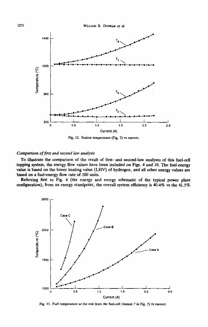
Inspection of the resulting temperature values shown in Fig. 12 reveals that the constraint of AT 3 44.4 K which has been imposed on the gas-to-gas heat exchange temperature differences, when applied to preheater 2 ( T6 - T4 and Ts - T,) is the limiting criterion at the low end of the range of operating current. Figure 12 displays that for case A these temperature criteria are satisfied above a current value of 0.5 A. Similarly, for cases B and C, the low limit of operable current is 0.2 A (for both cases).
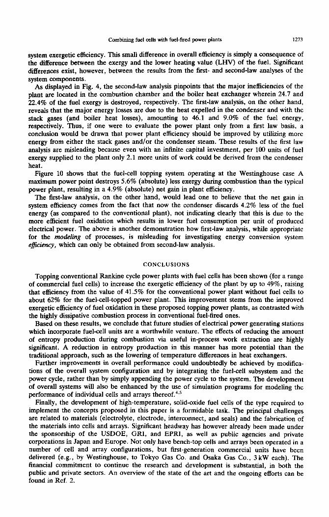
The limiting criteria for the high end of operating current is the fuel temperature at the fuel-cell unit exit (T,). The limiting currents, in this case are 1.6, 1.0, and 0.3 A for case A, B, and C, respectively (Fig. 13). The upper end of this range could be raised by integrating preheater 2 and the fuel-cell unit, that by transferring heat during fuel-cell operation.
1580 -
1505 -
= i.i 1430 -
=i 5 ? 0 1355 -
:
B 1280 -
g m
z 1205 - E 0, 5
1130 -
1055 -
4
*-*--r- \ Case 1
(No fuel cell)
0 900 1800 2700 3600 4500
Temperature (K)
Fig. 11. Chemical reaction affinity experienced in the boiler combustion chamber (see Table 2).
1272 WILLIAM R. DUNBAR et al
0. 1400 - /.
T8\/.00"
0' ./ 0)
./ .M 0.
r* A*-
.A/. -0-o
T4\ 1000 - .~8=.-.-*-.-.-.-.-.-.-.-. -.-.-.-.-.-.-.-.-.
g
5 1 ii 2 .A.
.' ? ./
600 - T8\._.~.'
0' .'
l '
l Hm _.(.
H.0
-0-m 4O-.H
“-.=~=:-.-.-m-._._. l T3\
_ _a-o-m-o-.-m-.-m-.-.-m
200 I I I I 1
0 0.5 1.0 1.5 2.0 2.5
Current (A)
Fig. 12. Station temperature (Fig. 2) vs current.
Comparison of first and second law analysis
To illustrate the comparison of the result of first- and second-law analyses of this fuel-cell topping system, the energy flow values have been included on Figs. 4 and 10. The fuel-energy value is based on the lower heating value (LHV) of hydrogen, and all other energy values are based on a fuel-energy flow rate of 100 units.
Referring first to Fig. 4 (the energy and exergy schematic of the typical power plant configuration), from an energy standpoint, the overall system efficiency is 40.4% vs the 41.5%
2500 -
.
Case C
\
I . .
I
/ , Case 0
.
/ .‘. . .
/
.’
_ I
.’
i
.’ l ” Case *
1500 . i
I
.' .'
.’
i Am /
. /* 0. /do
/' ,.R'
l /m /...H.Mm
.*. r.
1000 I I I I I
0 0.5 1.0 1.5 2.0 2.5
Current (A)
Fig. 13. Fuel temperature at the exit from the fuel-cell (station 7 in Fig. 2) vs current.
Combining fuel cells with fuel-fired power plants 1273
system exergetic efficiency. This small difference in overall efficiency is simply a consequence of the difference between the exergy and the lower heating value (LHV) of the fuel. Significant differences exist, however, between the results from the first- and second-law analyses of the system components.
As displayed in Fig. 4, the second-law analysis pinpoints that the major inefficiencies of the plant are located in the combustion chamber and the boiler heat exchanger wherein 24.7 and 22.4% of the fuel exergy is destroyed, respectively. The first-law analysis, on the other hand, reveals that the major energy losses are due to the heat expelled in the condenser and with the stack gases (and boiler heat losses), amounting to 46.1 and 9.0% of the fuel energy, respectively. Thus, if one were to evaluate the power plant only from a first law basis, a conclusion would be drawn that power plant efficiency should be improved by utilizing more energy from either the stack gases and/or the condenser steam. These results of the first law analysis are misleading because even with an infinite capital investment, per 100 units of fuel exergy supplied to the plant only 2.1 more units of work could be derived from the condenser heat.
Figure 10 shows that the fuel-cell topping system operating at the Westinghouse case A maximum power point destroys 5.6% (absolute) less exergy during combustion than the typical power plant, resulting in a 4.9% (absolute) net gain in plant efficiency.
The first-law analysis, on the other hand, would lead one to believe that the net gain in
system efficiency comes from the fact that now the condenser discards 4.2% less of the fuel energy (as compared to the conventional plant), not indicating clearly that this is due to the more efficient fuel oxidation which results in lower fuel consumption per unit of produced electrical power. The above is another demonstration how first-law analysis, while appropriate for the modeling of processes, is misleading for investigating energy conversion system efficiency, which can only be obtained from second-law analysis.
CONCLUSIONS
Topping conventional Rankine cycle power plants with fuel cells has been shown (for a range of commercial fuel cells) to increase the exergetic efficiency of the plant by up to 49%, raising that efficiency from the value of 41.5% for the conventional power plant without fuel cells to about 62% for the fuel-cell-topped power plant. This improvement stems from the improved exergetic efficiency of fuel oxidation in these proposed topping power plants, as contrasted with the highly dissipative combustion process in conventional fuel-fired ones.
Based on these results, we conclude that future studies of electrical power generating stations which incorporate fuel-cell units are a worthwhile venture. The effects of reducing the amount of entropy production during combustion via useful in-process work extraction are highly significant. A reduction in entropy production in this manner has more potential than the traditional approach, such as the lowering of temperature differences in heat exchangers.
Further improvements in overall performance could undoubtedly be achieved by modifica- tions of the overall system configuration and by integrating the fuel-cell subsystem and the power cycle, rather than by simply appending the power cycle to the system. The development of overall systems will also be enhanced by the use of simulation programs for modeling the performance of individual cells and arrays thereof.4*5
Finally, the development of high-temperature, solid-oxide fuel cells of the type required to implement the concepts proposed in this paper is a formidable task. The principal challenges are related to materials (electrolyte, electrode, interconnect, and seals) and the fabrication of the materials into cells and arrays. Significant headway has however already been made under the sponsorship of the USDOE, GRI, and EPRI, as well as public agencies and private
corporations in Japan and Europe. Not only have bench-top cells and arrays been operated in a number of cell and array configurations, but first-generation commercial units have been delivered (e.g., by Westinghouse, to Tokyo Gas Co. and Osaka Gas Co., 3 kW each). The financial commitment to continue the research and development is substantial, in both the public and private sectors. An overview of the state of the art and the ongoing efforts can be found in Ref. 2.

1274
Acknowledgements-One of Engineers for a Forgivable Fellowship.
WILLIAM R. DUNBAR et al
the authors (WRD) would like to express his gratitude to the Society of Automotive Loan Award and to the University of Pennsylvania for the award of a University
REFERENCES
1.
2.
3. 4.
5.
6. 7.
8.
9.
10.
11.
12.
13.
A. J. Appleby, Fuel-Cells: Trends in Research and Applications, Hemisphere, Washington, DC (1987). “International Energy Agency (IEA) Workshop Proceedings on Natural Gas Fuelled Solid Oxide Fuel Cells and Systems,” Office Federal de L’Energie, OFEN, CH-3003, Bern, Switzerland (September 1989). _ E. F. Obert and R. A. Gaggioli, Thermodynamics, McGraw-Hill, New York, NY (1963). W. R. Dunbar, “Computer Simulation of a High-Temperature Solid-Electrolyte Fuel Cell,” M.S. Thesis, Marquette University, Milwaukee (May 1983). W. R. Dunbar and R. A. Gaggioli, “Modeling of Solid Electrolyte Fuel Cells,” in Proc. World Energy Conf., Florence, Italy, pp. 49-60, Pergamon Press, Oxford (June 1990). K. S. Spiegler, Principles of Energetics, Springer, Berlin (1983). R. A. Gaggioli, J. J. Yoon, S. A. Patulski A. J. Latus, and E. F. Obert, “Pinpointing the Real Inefficiencies in Power Plants and Energy Systems,” in Proc. Am. Power Conf., pp. 671-679, R. A. Gaggioli ed., Washington, DC (1975). J. 0. Hirschfelder, C. F. Curtiss, and R. B. Bird, Molecular Theory of Gases and Liquids, Wiley, New York, NY (1954). S. R. DeGroot and P. Mazur, Nonequilibrium Thermodynamics, North-Holland, New York, NY (1962). W. R. Dunbar and N. Lior, “A Breakdown of the Exergy Losses in Combustion,” in Proc. World Energy Conf., Florence, Italy, pp. 347-358, Pergamon Press, Oxford (June 1990). W. C. Reynolds and H. C. Perkins, Engineering Thermodynamics, McGraw-Hill, New York, NY (1977). L. Rodriguez, “Calculation of Available Energy Quantities,” in Thermodynamics: Second Law Analysis (ACS Symposium Series), Chap. 3, R. A. Gaggioli ed., Washington, DC (1980). D. H. Archer, R. L. Zahradnik, E. F. Sverdup, W. A. English, L. Elikan, and J. J. Alles, “Solid Electrolyte Batteries,” in Proc. I&h Ann. Power Sources Conf., pp. 36-40, Atlantic City, NJ (May 1964).
NOMENCLATURE
ac- = Specific chemical exergy (kJ/kgmol) a, = Specific flow exergy (kJ/kgmol)
aTM = Specific thermal mechanical exergy (kJ/kgmol)
cp = Molar specific heat (kJ/kgmol-K) E = Convective energy rate (kJ/s) h = Specific enthalpy (kJ/kgmol) N = Molar flow rate (kgmol/sec)
Np = Molar production rate (kgmol/sec) P = Pressure (kPa) PO = Atmospheric pressure (kPa) Q = Heat transfer rate (kJ/sec) R = Universal gas constant (kJ/kgmol-K)
Rf = Fuel consumption rate (kgmol/sec) s = Specific entropy (kJ/kgmol-K)
S, = Entropy production (kJ/K) T = Temperature (K) G = Reference temperature (K) W = Work output rate (kJ/sec) A = Exergy rate (kJ/sec)
A, = Exergy destruction rate (kJ/sec) I = Chemical affinity (kJ/kgmol) p= Electrochemical potential (kJ/kgmol) v = Stoichiometric coefficient (kgmol/kgmol
fuel) x = Mole fraction