Embed Size (px)
Citation preview
Combustion and Flame 160 (2013) 1650–1656
Contents lists available at SciVerse ScienceDirect
Combustion and Flame
journal homepage: www.elsevier .com/locate /combustflame
Sooting behaviour of n-heptane laminar diffusion flames at highpressures
0010-2180/$ - see front matter � 2013 The Combustion Institute. Published by Elsevier Inc. All rights reserved.http://dx.doi.org/10.1016/j.combustflame.2013.03.008
⇑ Corresponding author. Fax: +1 416 667 7799.E-mail address: [email protected] (Ö.L. Gülder).
Ahmet E. Karatas�, Gorngrit Intasopa, Ömer L. Gülder ⇑Institute for Aerospace Studies, University of Toronto, 4925 Dufferin Street, Toronto, ON, Canada M3H 5T6
a r t i c l e i n f o a b s t r a c t
Article history:Received 25 December 2012Received in revised form 13 February 2013Accepted 5 March 2013Available online 3 April 2013
Keywords:High-pressure sootn-HeptaneSoot yieldDiffusion flamesLiquid fuel
The effect of pressure on sooting behaviour of n-heptane is studied in co-flow n-heptane/air laminar dif-fusion flames at pressures above atmospheric in a high pressure combustion chamber. The fuel is dilutedwith either nitrogen or helium to keep a non-smoking flame at elevated pressures, and the selected fuelmass flow rate of n-heptane provided diffusion flames in which the soot was completely oxidized withinthe visible flame envelope. The flame stability proved to be a challenge and stable flames were possibleonly at certain pressures for a sufficiently long duration to permit measurements. The soot volumefractions and temperatures were measured by spectral soot emission as a function of pressure for nitro-gen-diluted n-heptane flames at 2, 5 and 7 atm. For helium-diluted n-heptane flames, line of sight sootemission data at 3, 4, and 5 atm are presented at two heights above the burner exit. Comparison oflimited nitrogen-diluted n-heptane data to previous measurements of soot yields indicate that sootformation in diffusion flames of n-heptane seems to be slightly more sensitive to pressure than that inaliphatic gaseous fuel diffusion flames within the pressure range considered in this work.
� 2013 The Combustion Institute. Published by Elsevier Inc. All rights reserved.
1. Introduction
The highly complex nature of hydrocarbon diffusion flamesposes challenges in unraveling the underpinning physical andchemical mechanisms of soot formation and oxidation. As a resultonly a few principles are firmly established mostly for atmosphericgaseous fuel diffusion flames. For liquid fuels, we still rely onsmoke point of the fuel or sooting index for practical applicationsdue to a lack of full understanding of the effects of the variousoperating conditions on the soot formation process [1,2]. Earlier ef-forts to link the smoke point and sooting tendency of liquid fuels tochemical structure of the fuel were successful [3,4], and they pro-vided scaling information for further studies on sooting propensi-ties of hydrocarbons, see e.g., [5].
The overall reaction rate in hydrocarbon–air combustion (i.e.,combustion intensity or heat release per unit volume) scalesapproximately with the square of the operating pressure, thusthe relative size of the combustion device gets smaller as the oper-ating pressure is increased for a required power output. In spite ofthe fact that most combustion devices used for transportationoperate at elevated pressures (e.g., aircraft gas turbines up to40 atm, diesel engines exceeding 100 atm), our understanding ofsoot formation at these pressures is not at a desirable level, and
there is a lack of bench-mark experimental data and complemen-tary predictive models [6].
In practical diffusion combustion systems, such as diesel andaircraft gas turbine engines, and in fires the combustion is turbu-lent. However, the high level of intermittency and relatively short-er residence times associated with turbulent diffusion flames limitthe experimental accessibility of these flames and make it difficultto track combustion events like soot formation. Further thenon-homogeneous nature of turbulent diffusion flames makes itchallenging to isolate parameters that affect soot formation andoxidation. One of the most widely used approximations to exploitsimilarities between laminar and turbulent diffusion flames is touse the laminar flamelet concept (or approaches based on flam-elets), which provides a tractable flame model [7–9]. For this rea-son, most of the soot studies at elevated pressures have beendone in laminar diffusion flames of co-flow type, which permit toisolate the parameters that influence the soot formation process.
Experimental research in laminar diffusion flames at pressuresabove atmospheric have been held back by the challenges indesigning an experimental apparatus and in operating instrumentsthat require accessibility for intrusive and non-intrusive measure-ment techniques [7]. In addition, the stability of laminar diffusionflames, especially originating from buoyancy effects, becomes animportant issue at elevated pressures due to the increase inGrashoff number, which scales with the square of pressure.These impediments have limited the number and the extent of
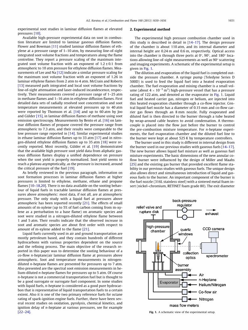
Fig. 1. A schematic view of the experimental setup.
A.E. Karatas� et al. / Combustion and Flame 160 (2013) 1650–1656 1651
experimental soot studies in laminar diffusion flames at elevatedpressures [10].
Available high-pressure experimental data on soot in combus-tion literature are limited to laminar gaseous diffusion flames.Flower and Bowman [11] studied laminar diffusion flames of eth-ylene at a pressure range of 1–10 atm, by measuring line-of-sightintegrated soot volume fractions and temperatures along the flamecentreline. They report a pressure scaling of the maximum inte-grated soot volume fraction with an exponent of 1.2 ± 0.1 fromatmospheric to 10 atm pressure for ethylene diffusion flames. Mea-surements of Lee and Na [12] indicate a similar pressure scaling forthe maximum soot volume fraction with an exponent of 1.26 inlaminar ethylene flames from 2 atm to 4 atm. McCrain and Roberts[13] measured path integrated and local soot volume fractions byline-of-sight attenuation and laser-induced incandescence, respec-tively. Their measurements covered a pressure range of 1–25 atmin methane flames and 1–16 atm in ethylene diffusion flames. Firstdetailed data sets of radially resolved soot concentration and soottemperature measurements at elevated pressures up to 40 atmwere reported by Thomson et al. [14] and up to 60 atm by Jooand Gülder [15], in laminar diffusion flames of methane using sootemission spectroscopy. Measurements by Bento et al. [16] on lam-inar diffusion flames of propane covered the pressure range fromatmospheric to 7.3 atm, and their results were comparable to thelow pressure range reported in [14]. Similar experimental studiesin ethane laminar diffusion flames up to 33 atm [17] and in nitro-gen-diluted ethylene diffusion flames up to 35 atm [18] were re-cently reported. Most recently, Gülder et al. [19] demonstratedthat the available high pressure soot yield data from aliphatic gas-eous diffusion flames display a unified dependence on pressurewhen the soot yield is properly normalized. Soot yield seems toreach a plateau asymptotically, as the pressure is increased, aroundthe critical pressure of the fuel [19].
As briefly reviewed in the previous paragraph, information onsoot formation processes in laminar diffusion flames at higherpressures is limited to ethylene, methane, ethane and propaneflames [10–18,20]. There is no data available on the sooting behav-iour of liquid fuels in tractable laminar diffusion flames at pres-sures above atmospheric: most data, if not all, are at atmosphericpressure. The only study with a liquid fuel at pressures aboveatmospheric has been reported recently [21]. The effects of smallamounts of m-xylene (up to 5% of fuel carbon coming from m-xy-lene as a perturbation to a base flame) on aromatic species andsoot were studied in a nitrogen-diluted ethylene flame between1 and 5 atm. Their results indicate that the observed increase insoot and aromatic species are about first order with respect toamount of m-xylene added to the flame [21].
Liquid fuels currently used in air and ground transportation aremostly petroleum based, and they contain hundreds of differenthydrocarbons with various properties dependent on the sourceand the refining process. The main objective of the research re-ported in this paper was to determine the sooting behaviour of aco-flow n-heptane/air laminar diffusion flame at pressures aboveatmospheric. Soot and temperature measurements in nitrogen-diluted n-heptane flames are presented for pressures up to 7 atm.Also presented are the spectral soot emission measurements in he-lium-diluted n-heptane flames for pressures up to 5 atm. Of coursen-heptane is not a commercial transportation fuel but is thought tobe a good surrogate or surrogate fuel component. In some studieswith liquid fuels, n-heptane is considered as a good pure hydrocar-bon that is representative of liquid transportation fuels to a certainextent. Also it is one of the two primary reference fuels for octanerating of spark-ignition engine fuels. Further, there have been sev-eral recent studies on oxidation, pyrolysis, chemical kinetics, andignition delay of n-heptane at various pressures, see for example[22–24].
2. Experimental method
The experimental high pressure combustion chamber used inthis study is described in detail in [14–17]. The design pressureof the chamber is about 110 atm, and its internal diameter andinternal height are 0.24 m and 0.6 m, respectively. Optical accessinto the chamber is through three ports at 0�, 90�, and 180� loca-tions allowing line-of-sight measurements as well as 90� scatteringand imaging experiments. A schematic of the experimental setup isgiven in Fig. 1.
The dilution and evaporation of the liquid fuel is completed out-side the pressure chamber. A syringe pump (Teledyne Series D500D) is used to feed the liquid fuel into a heated evaporationchamber. The fuel evaporation and mixing chamber is a small vol-ume (about 4 � 10�5 m3) high-pressure vessel that has a pressurerating of 122 atm, and denoted as the evaporator in Fig. 1. Liquidfuel and heated carrier gas, nitrogen or helium, are injected intothis heated evaporation chamber through a co-flow injector. Cen-tral liquid fuel nozzle has a diameter of 0.15 mm and co-flow car-rier gas flows through an 8 mm nozzle. Fully evaporated anddiluted fuel is then directed to the burner through a tube heatedby wrap-around cable heaters to avoid condensation. A thermo-couple is placed into the flow just before the burner to controlthe pre-combustion mixture temperature. For n-heptane experi-ments, the fuel evaporation chamber and the diluted fuel line tothe burner were kept at about 525 K by temperature controllers.
The burner used in this study is different in internal design fromthe burner used in our previous studies with gaseous fuels [14–17].The new burner allows liquid fuel mixture as well as gaseous fuelmixture experiments. The basic dimensions of the new annular co-flow burner were influenced by the design of Miller and Maahs[25] and the existing gas burner that provided excellent flame sta-bility in our previous studies with gaseous fuels. The unique designalso allows direct and simultaneous introduction of liquid and gas-eous fuels to the burner. An important component of the burner isthe fuel nozzle (316L stainless steel) with a sintered metal foam in-sert (nickel–chromium, RETINET foam grade 80). The exit diameter
1652 A.E. Karatas� et al. / Combustion and Flame 160 (2013) 1650–1656
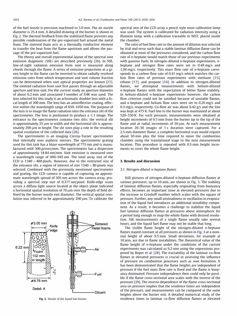
of the fuel nozzle is precision machined to 3.0 mm. The air nozzlediameter is 25.4 mm. A detailed drawing of the burner is shown inFig. 2. The thermal feedback from the stabilized flame prevents anypossible condensation of the pre-vaporized fuel around the metalfoam. The sintered foam acts as a thermally conductive elementto transfer the heat from the flame upstream and allows the pas-sage of the pre-vaporized fuel.
The theory and overall experimental layout of the spectral sootemission diagnostic (SSE) are described previously [26]. In SSE,line-of-sight radiation emission from soot is measured alongchords through the flame. A series of emission projections at a gi-ven height in the flame can be inverted to obtain radially resolvedemission rates from which temperature and soot volume fractioncan be determined when soot optical properties are known [27].The emitted radiation from soot first passes through an adjustableaperture and lens unit. For the current study an aperture diameterof about 6.2 mm and associated f-number of f/48 was used. Thelens selected for this study is an achromatic doublet lens with a fo-cal length of 300 mm. The lens has an antireflective coating, effec-tive within the wavelength range of 650–1050 nm. The purpose ofthe lens is to image the flame radiation onto the entrance slit of thespectrometer. The lens is positioned to produce a 1:1 image. Theentrance to the spectrometer contains two slits: the vertical slitis approximately 25 lm in width and the horizontal slit is approx-imately 290 lm in height. The slit sizes play a role in the resultingspatial resolution of the collected data [26].
The spectrometer is an imaging Czerny-Turner spectrometerthat internally uses aspheric mirrors. The spectrometer gratingused for this task has a blaze wavelength of 775 nm and is manu-factured with 300 groves/mm. The spectrometer has a dispersionof approximately 18.84 nm/mm. Soot emission is measured overa wavelength range of 690–945 nm. The total array size of theCCD is 1340 � 400 pixels. However, due to the restricted size ofthe entrance slit, a region of interest of size 1340 � 80 pixels wasselected. Combined with the previously mentioned spectrometerand grating, the CCD camera is capable of capturing an approxi-mate wavelength spread of 505 nm across the camera array, pro-viding a spectral step size of 0.377 nm/pixel. Knife-edge scansacross a diffuse light source located at the object plane indicateda horizontal spatial resolution of 70 lm over the depth of field de-fined by the burner nozzle exit diameter. The vertical spatial reso-lution was inferred to be approximately 290 lm. To calibrate the
Fig. 2. Details of the liquid fuel burner.
spectral axis of the CCD array a pencil style neon calibration lampwas used. The system is calibrated for radiation intensity using afilament lamp, with a calibration traceable to NIST, placed insidethe chamber.
The ratio of fuel flow rate to the amount of dilution was selectedby trial and error such that a stable laminar diffusion flame can beobtained at most of the pressures considered, and the carbon flowrate of n-heptane would match those of our previous experimentswith gaseous fuels. In nitrogen-diluted n-heptane experiments, n-heptane and nitrogen flow rates were set to 0.49 mg/s and1.04 mg/s, respectively. This mass flow rate of n-heptane corre-sponds to a carbon flow rate of 0.41 mg/s which matches the car-bon flow rates of previous experiments with methane [15],ethane [17], and propane [16]. In addition to nitrogen-dilutedflames, we attempted measurements with helium-dilutedn-heptane flames with the expectation of better flame stability.In helium-diluted n-heptane experiments however, the carbonflow criterion could not be satisfied because of unstable flames,and n-heptane and helium flow rates were set to 0.29 mg/s and0.3 mg/s, respectively. Co-flow air was about 0.42 g/s and the linewas kept at 475 K. Fuel line to the burner was maintained at about520–530 K. For each pressure, measurements were obtained atheight increments of 0.5 mm from the burner tip to the tip of theflame and at radial increments of 50 lm. At each measurementlocation 20–30 images of 1 s duration were captured. For a2.5 mm diameter flame, a complete horizontal scan would requireabout 50 min plus the time required to move the combustionchamber using the translational stage to the next measurementlocation. This procedure is repeated with 0.5 mm height incre-ments to cover the whole flame height.
3. Results and discussion
3.1. Nitrogen-diluted n-heptane flames
Still pictures of nitrogen-diluted n-heptane diffusion flames atvarious pressures, up to 10 atm, are shown in Fig. 3. The stabilityof laminar diffusion flames, especially originating from buoyancyeffects, becomes an important issue at elevated pressures due tothe increase in Grashoff number which scales with the square ofpressure. Further, any small unsteadiness or oscillation in evapora-tion of the liquid fuel introduces an additional instability compo-nent. As a result, it becomes a challenge to stabilize the liquidfuel laminar diffusion flames at pressures above atmospheric fora period long enough to map the whole flame with desired resolu-tion. SSE measurements of a single flame usually take severalhours, and the liquid fuel flame may not be stable that long.
The visible flame height of the nitrogen-diluted n-heptaneflames stayed constant at all pressures as shown in Fig. 3 at a nom-inal height of about 9.5 mm. Small deviations, for example at10 atm, are due to flame instabilities. The theoretical value of theflame height of n-heptane under the conditions of the currentexperiments was calculated as 9.2 mm using the expressions pro-posed by Roper et al. [28]. The tractability of the laminar co-flowflames at elevated pressures is crucial in assessing the influenceof pressure on combustion processes such as soot formation. Ithas been demonstrated that the flame heights are independent ofpressure if the fuel mass flow rate is fixed and the flame is buoy-ancy dominated. Pressure independence then could only be possi-ble if the flame cross-sectional area scales with the inverse of thepressure [29]. The inverse dependence of the flame cross-sectionalarea on pressure implies that the residence times are independentof the pressure, and measurements can be compared at the sameheights above the burner exit. A detailed numerical study of theresidence times in laminar co-flow diffusion flames at elevated
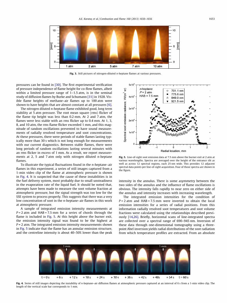
Fig. 3. Still pictures of nitrogen-diluted n-heptane flames at various pressures.
Fig. 5. Line-of-sight soot emission data at 7.5 mm above the burner exit at 2 atm atvarious wavelengths. Spectra are averaged over the height of the entrance slit aswell as across 12 spectral regions, each 25 nm wide. This provides 12 adjacentspectral data points per line-of-sight acquisition. Four of those spectra are shown inthe figure.
A.E. Karatas� et al. / Combustion and Flame 160 (2013) 1650–1656 1653
pressures can be found in [30]. The first experimental verificationof pressure independence of flame height for co-flow flames, albeitwithin a limited pressure range of 1–1.5 atm, is in the seminalstudy of diffusion flames by Burke and Schumann [31] in 1928. Vis-ible flame heights of methane–air flames up to 100 atm wereshown to have heights that are almost constant at all pressures [6].
The nitrogen diluted n-heptane flame exhibited good, long termstability at 5 atm pressure. The root mean square (rms) flicker ofthe flame tip height was less than 0.2 mm. At 2 and 7 atm, theflames were less stable with an rms flicker up to 0.4 mm. At 1, 3,8, and 10 atm, the rms flame flicker exceeded 1 mm, and this mag-nitude of random oscillations prevented to have sound measure-ments of radially resolved temperature and soot concentrations.At these pressures, there were periods of stable flames lasting typ-ically more than 30 s which is not long enough for measurementswith our current diagnostics. Between stable flames, there werelong periods of random oscillations lasting several minutes withan rms flicker in excess of 1 mm. As a result, we report measure-ments at 2, 5 and 7 atm only with nitrogen diluted n-heptaneflames.
To illustrate the typical fluctuations found in the n-heptane–airflames in this experiment, a series of still images captured from a1-min video clip of the flame at atmospheric pressure is shownin Fig. 4. It is suspected that the cause of these instabilities is inthe fuel delivery system, most probably due to small unsteadinessin the evaporation rate of the liquid fuel. It should be noted that,attempts have been made to measure the soot volume fraction atatmospheric pressure, but the signal strength was too low for theSSE system to process properly. This suggests that there was a verylow concentration of soot in the n-heptane–air flames in this workat atmospheric pressure.
A sample of integrated emission intensity measurements atP = 2 atm and HAB = 7.5 mm for a series of chords through theflame is included in Fig. 5. At this height above the burner exit,the emission intensity signal was found to be the highest atP = 2 atm. The integrated emission intensity measurements shownin Fig. 5 indicate that the flame has an annular emission structure,and the centreline intensity is about 40–50% lower than the peak
Fig. 4. Series of still images depicting the instability of n-heptane–air diffusion flames alength of the vertical scale bar corresponds to 1 mm.
intensity in the annulus. There is some asymmetry between thetwo sides of the annulus and the influence of flame oscillations isobvious. The intensity falls rapidly to near zero on either side ofthe annulus and intensity increases with increasing wavelength.
The integrated emission intensities for the condition ofP = 2 atm and HAB = 7.5 mm were inverted to obtain the localemission intensities for a series of radial positions. From thisinformation radially resolved soot temperatures and soot volumefractions were calculated using the relationships described previ-ously [14,26]. Briefly, horizontal scans of line-integrated spectraare collected over a spectral range of 690–945 nm. Inversion ofthese data through one-dimensional tomography using a three-point Abel inversion yields radial distributions of the soot radiationfrom which temperature profiles are extracted. From an absolute
t atmospheric pressure captured at an interval of 6 s from a 1-min video clip. The

Fig. 7. Radial distributions of soot volume fraction at various heights above theburner exit at 5 atm.
Fig. 8. Radial distributions of soot volume fraction at various heights above theburner exit at 7 atm.
1654 A.E. Karatas� et al. / Combustion and Flame 160 (2013) 1650–1656
calibration of the flame emission and by use of these temperaturedata, absorption coefficients are calculated, which are directly pro-portional to the soot volume fractions [26]. Calculated soot volumefraction and temperature profiles are shown in Fig. 6. The soot vol-ume fraction profile displays the expected annular structure; how-ever the effects of flame oscillations, as well as the relatively lowsoot emission signal, manifest itself (through the Abel inversionprocess) as oscillations in the soot volume fraction at radial loca-tions smaller than 1 mm. The radial temperature profile peaks ata larger radial location than the soot volume fraction profile as de-picted in Fig. 6. This is consistent with previous observations inethane diffusion flames [17].
Soot volume fraction profiles at 5 and 7 atm are shown in Figs. 7and 8, respectively, at several heights above the burner exit. Thestructure of the soot field is very similar to those reported for gas-eous diffusion flames at similar pressures [16,17]. Soot began toform in an annular ring at the height of about 3 mm above the bur-ner exit where the peak soot concentration was about 1.5 ppm, asdepicted in Fig. 7. As the height was increased, the peak soot con-centration increased and the location of the peak contracted to-wards the centreline. The soot volume distribution switchedfrom annular profiles to centre peak profiles at the height of6.5 mm and above. The maximum soot volume fraction at thispressure was found to be 12 ppm at the height of 7.5 mm abovethe nozzle tip. At heights beyond 7.5 mm, soot concentration de-creased as the axial height was increased further towards the flametip. A similar structure was observed at 7 atm for lower half of theflame as shown in Fig. 8. The data for the upper half of the flamewere extremely noisy (rms flicker exceeding 1 mm and lateral sideto side random movements) and were omitted from Fig. 8. Themaximum soot volume fraction was estimated to be about32 ppm at 5.5 mm height above the burner exit at 7 atm.
The radial temperature profiles for the n-heptane–air flames at5 atm are shown in Fig. 9 at various heights above the burner exit.The maximum temperature at 5 atm seems to stay slightly below2000 K. At 7 atm, on the other hand, the maximum temperatureis about 100 K lower than that at 5 atm, as shown in Fig. 10. Thelower temperatures observed at 7 atm is a manifestation of thehigher soot concentrations leading to relatively higher radiativeheat losses from the flame. The radial temperature profiles shownin Figs. 9 and 10 are similar to the profiles exhibited by gaseousfuel diffusion flames [15–17].
The sensitivity of the sooting propensity to pressure can be as-sessed by evaluating the variation of maximum soot yield withpressure. The soot yield is defined as the percentage of total carbon
Fig. 6. Radial distributions of soot volume fraction and temperature at 7.5 mmabove the burner exit at 2 atm.
Fig. 9. Radial distributions of temperature at various heights above the burner exitat 5 atm.
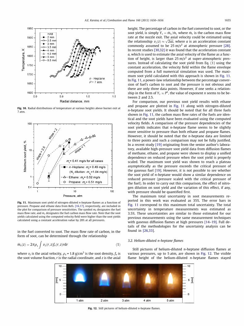
Fig. 10. Radial distributions of temperature at various heights above burner exit at7 atm.
Fig. 11. Maximum soot yield of nitrogen-diluted n-heptane flames as a function ofpressure. Propane and ethane data from Refs. [16,17], respectively, are included inthe plot for comparison of pressure sensitivities. The symbol mF designates the fuelmass flow rate, and mc designates the fuel carbon mass flow rate. Note that the sootyields calculated using the computed velocity field were higher than the soot yieldscalculated using a constant acceleration value by 28% at all pressures.
A.E. Karatas� et al. / Combustion and Flame 160 (2013) 1650–1656 1655
in the fuel converted to soot. The mass flow rate of carbon, in theform of soot, can be determined through the relationship
_msðzÞ ¼ 2pqs
Zvzðr; zÞfvðr; zÞrdr ð1Þ
where vz is the axial velocity, qs = 1.8 g/cm3 is the soot density, fv isthe soot volume fraction, r is the radial coordinate, and z is the axial
Fig. 12. Still pictures of helium
height. The percentage of carbon in the fuel converted to soot, or thesoot yield, is simply Ys ¼ _ms= _mc where _mc is the carbon mass flowrate at the nozzle exit. The axial velocity could be estimated usingthe relationship vzðzÞ �
ffiffiffiffiffiffiffiffi2azp
, where a is an acceleration constantcommonly assumed to be 25 m/s2 at atmospheric pressure [28].In recent studies [30,32] it was found that the acceleration constanta, which is used to estimate the axial velocity of the flame as a func-tion of height, is larger than 25 m/s2 at super-atmospheric pres-sures. Instead of calculating the soot yield from Eq. (1) using theconstant acceleration, the velocity field within the flame envelopecomputed from a full numerical simulation was used. The maxi-mum soot yield calculated with this approach is shown in Fig. 11.In Fig. 11, a power-law relationship between the percentage conver-sion of fuel’s carbon to soot and the pressure is not obvious andthere are only three data points. However, if one seeks a relation-ship in the form of Ys / Pn, the value of exponent n seems to be be-tween 2 and 2.5.
For comparison, our previous soot yield results with ethaneand propane are plotted in Fig. 11 along with nitrogen-dilutedn-heptane soot yields. It should be noted that for all three fuelsshown in Fig. 11, the carbon mass flow rates of the fuels are iden-tical and the soot yields have been evaluated using the computedvelocity fields. A comparison of the pressure dependencies of thesoot yields indicates that n-heptane flame seems to be slightlymore sensitive to pressure than both ethane and propane flames.However, it should be noted that the n-heptane data are limitedto three points and such a comparison may not be fully justified.In a recent study [19] originating from the senior author’s labora-tory, available high-pressure soot yield data from diffusion flamesof methane, ethane, and propane were shown to display a unifieddependence on reduced pressure when the soot yield is properlyscaled. The maximum soot yield was shown to reach a plateauasymptotically as the pressure exceeds the critical pressure ofthe gaseous fuel [19]. However, it is not possible to see whetherthe soot yield of n-heptane would show a similar dependence onreduced pressure (pressure scaled with the critical pressure ofthe fuel). In order to carry out this comparison, the effect of nitro-gen dilution on soot yield and the variation of this effect, if any,with pressure should be quantified first.
The maximum total uncertainty in soot measurements re-ported in this work was evaluated as 35%. The error bars inFig. 11 correspond to this maximum total uncertainty. The totaluncertainty in temperature measurements was estimated as3.5%. These uncertainties are similar to those estimated for ourprevious measurements using the same measurement techniqueswith gaseous diffusion flames at high pressures [14–19]. Full de-tails of the methodologies for the uncertainty analysis can befound in [26,33].
3.2. Helium-diluted n-heptane flames
Still pictures of helium-diluted n-heptane diffusion flames atvarious pressures, up to 5 atm, are shown in Fig. 12. The visibleflame height of the helium-diluted n-heptane flames stayed
-diluted n-heptane flames.
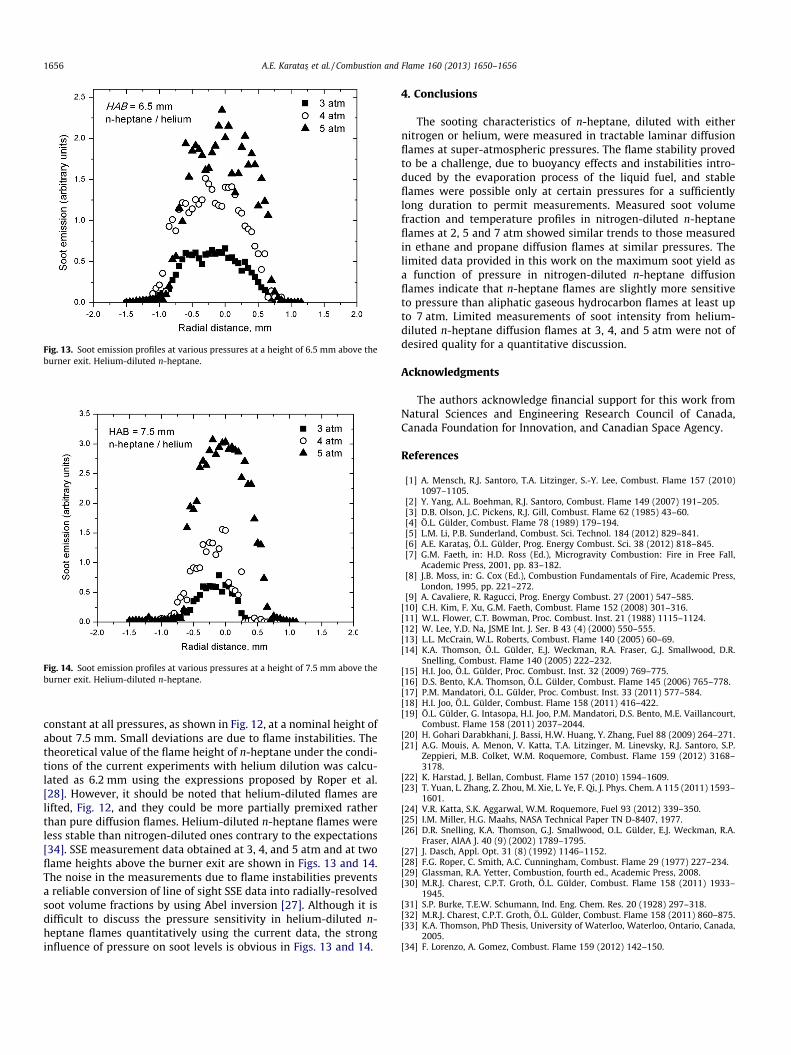
Fig. 13. Soot emission profiles at various pressures at a height of 6.5 mm above theburner exit. Helium-diluted n-heptane.
Fig. 14. Soot emission profiles at various pressures at a height of 7.5 mm above theburner exit. Helium-diluted n-heptane.
1656 A.E. Karatas� et al. / Combustion and Flame 160 (2013) 1650–1656
constant at all pressures, as shown in Fig. 12, at a nominal height ofabout 7.5 mm. Small deviations are due to flame instabilities. Thetheoretical value of the flame height of n-heptane under the condi-tions of the current experiments with helium dilution was calcu-lated as 6.2 mm using the expressions proposed by Roper et al.[28]. However, it should be noted that helium-diluted flames arelifted, Fig. 12, and they could be more partially premixed ratherthan pure diffusion flames. Helium-diluted n-heptane flames wereless stable than nitrogen-diluted ones contrary to the expectations[34]. SSE measurement data obtained at 3, 4, and 5 atm and at twoflame heights above the burner exit are shown in Figs. 13 and 14.The noise in the measurements due to flame instabilities preventsa reliable conversion of line of sight SSE data into radially-resolvedsoot volume fractions by using Abel inversion [27]. Although it isdifficult to discuss the pressure sensitivity in helium-diluted n-heptane flames quantitatively using the current data, the stronginfluence of pressure on soot levels is obvious in Figs. 13 and 14.
4. Conclusions
The sooting characteristics of n-heptane, diluted with eithernitrogen or helium, were measured in tractable laminar diffusionflames at super-atmospheric pressures. The flame stability provedto be a challenge, due to buoyancy effects and instabilities intro-duced by the evaporation process of the liquid fuel, and stableflames were possible only at certain pressures for a sufficientlylong duration to permit measurements. Measured soot volumefraction and temperature profiles in nitrogen-diluted n-heptaneflames at 2, 5 and 7 atm showed similar trends to those measuredin ethane and propane diffusion flames at similar pressures. Thelimited data provided in this work on the maximum soot yield asa function of pressure in nitrogen-diluted n-heptane diffusionflames indicate that n-heptane flames are slightly more sensitiveto pressure than aliphatic gaseous hydrocarbon flames at least upto 7 atm. Limited measurements of soot intensity from helium-diluted n-heptane diffusion flames at 3, 4, and 5 atm were not ofdesired quality for a quantitative discussion.
Acknowledgments
The authors acknowledge financial support for this work fromNatural Sciences and Engineering Research Council of Canada,Canada Foundation for Innovation, and Canadian Space Agency.
References
[1] A. Mensch, R.J. Santoro, T.A. Litzinger, S.-Y. Lee, Combust. Flame 157 (2010)1097–1105.
[2] Y. Yang, A.L. Boehman, R.J. Santoro, Combust. Flame 149 (2007) 191–205.[3] D.B. Olson, J.C. Pickens, R.J. Gill, Combust. Flame 62 (1985) 43–60.[4] Ö.L. Gülder, Combust. Flame 78 (1989) 179–194.[5] L.M. Li, P.B. Sunderland, Combust. Sci. Technol. 184 (2012) 829–841.[6] A.E. Karatas�, Ö.L. Gülder, Prog. Energy Combust. Sci. 38 (2012) 818–845.[7] G.M. Faeth, in: H.D. Ross (Ed.), Microgravity Combustion: Fire in Free Fall,
Academic Press, 2001, pp. 83–182.[8] J.B. Moss, in: G. Cox (Ed.), Combustion Fundamentals of Fire, Academic Press,
London, 1995, pp. 221–272.[9] A. Cavaliere, R. Ragucci, Prog. Energy Combust. 27 (2001) 547–585.
[10] C.H. Kim, F. Xu, G.M. Faeth, Combust. Flame 152 (2008) 301–316.[11] W.L. Flower, C.T. Bowman, Proc. Combust. Inst. 21 (1988) 1115–1124.[12] W. Lee, Y.D. Na, JSME Int. J. Ser. B 43 (4) (2000) 550–555.[13] L.L. McCrain, W.L. Roberts, Combust. Flame 140 (2005) 60–69.[14] K.A. Thomson, Ö.L. Gülder, E.J. Weckman, R.A. Fraser, G.J. Smallwood, D.R.
Snelling, Combust. Flame 140 (2005) 222–232.[15] H.I. Joo, Ö.L. Gülder, Proc. Combust. Inst. 32 (2009) 769–775.[16] D.S. Bento, K.A. Thomson, Ö.L. Gülder, Combust. Flame 145 (2006) 765–778.[17] P.M. Mandatori, Ö.L. Gülder, Proc. Combust. Inst. 33 (2011) 577–584.[18] H.I. Joo, Ö.L. Gülder, Combust. Flame 158 (2011) 416–422.[19] Ö.L. Gülder, G. Intasopa, H.I. Joo, P.M. Mandatori, D.S. Bento, M.E. Vaillancourt,
Combust. Flame 158 (2011) 2037–2044.[20] H. Gohari Darabkhani, J. Bassi, H.W. Huang, Y. Zhang, Fuel 88 (2009) 264–271.[21] A.G. Mouis, A. Menon, V. Katta, T.A. Litzinger, M. Linevsky, R.J. Santoro, S.P.
Zeppieri, M.B. Colket, W.M. Roquemore, Combust. Flame 159 (2012) 3168–3178.
[22] K. Harstad, J. Bellan, Combust. Flame 157 (2010) 1594–1609.[23] T. Yuan, L. Zhang, Z. Zhou, M. Xie, L. Ye, F. Qi, J. Phys. Chem. A 115 (2011) 1593–
1601.[24] V.R. Katta, S.K. Aggarwal, W.M. Roquemore, Fuel 93 (2012) 339–350.[25] I.M. Miller, H.G. Maahs, NASA Technical Paper TN D-8407, 1977.[26] D.R. Snelling, K.A. Thomson, G.J. Smallwood, O.L. Gülder, E.J. Weckman, R.A.
Fraser, AIAA J. 40 (9) (2002) 1789–1795.[27] J. Dasch, Appl. Opt. 31 (8) (1992) 1146–1152.[28] F.G. Roper, C. Smith, A.C. Cunningham, Combust. Flame 29 (1977) 227–234.[29] Glassman, R.A. Yetter, Combustion, fourth ed., Academic Press, 2008.[30] M.R.J. Charest, C.P.T. Groth, Ö.L. Gülder, Combust. Flame 158 (2011) 1933–
1945.[31] S.P. Burke, T.E.W. Schumann, Ind. Eng. Chem. Res. 20 (1928) 297–318.[32] M.R.J. Charest, C.P.T. Groth, Ö.L. Gülder, Combust. Flame 158 (2011) 860–875.[33] K.A. Thomson, PhD Thesis, University of Waterloo, Waterloo, Ontario, Canada,
2005.[34] F. Lorenzo, A. Gomez, Combust. Flame 159 (2012) 142–150.


![Cyclosporine oral solution [MODIFIED] diluted with orange](https://img.pdfslide.net/doc/110x75/61c6faa1af22391b7f5175cd/cyclosporine-oral-solution-modified-diluted-with-orange-.jpg)