Embed Size (px)
Citation preview

White Paper
June 2021
www.spartancontrols.com
Combustion Management
Meeting the Challenges of BMS Applications Burner Management Solutions

White Paper
June 2021 Burn Management Solutions
www.spartancontrols.com
Meeting the Challenges of Burner Management Applications
A Burner Management System (BMS), also sometimes referred to as a Flame Safety System
(FSS), is a critical component of a combustion process whether it be a boiler, heater, kiln, dryer,
thermal oxidizer, incinerator or other unit. This is the system that protects against hazardous
firing conditions, which could result in harm to the process equipment and any personnel around
it.
First and foremost, a BMS sequences the initial firing to ensure safe light‐off and monitors the
process to shut it down if an unsafe situation is detected. It is also important that the BMS
provides functionality to assist operations in smoothly starting the combustion process and in
troubleshooting the situation when problems occur. Finally, the BMS must be cost effective to
implement and maintain while being highly reliable over the long term.
Burner Management Application Challenges
Code Compliance.
A BMS must be designed and implemented in accordance with applicable safety codes
for the process and the site location.
Holistic Approach.
All combustion process aspects, including piping, field devices, control platform, and
sequence configuration must be considered in BMS design SIL Rated Platform. It is
recommended that the flame safety configuration be implemented on a Safety
Instrumented System (SIS) hardware platform.
Devices and Elements.
Most BMS issues occur in measurement devices and final elements; use of transmitters
rather than switches and smart devices is recommended. Separate but Integrated BMS
logic must reside in separate control hardware, but an integrated safety platform solution
delivers optimal performance and cost.
Logic Configuration
The burner sequence configuration should be straightforward to understand and
maintain.

White Paper
June 2021 Burn Management Solutions
www.spartancontrols.com
Operator Information
Clear indication of the status of the firing sequence needs to be presented to operations
personnel to assist in process start‐up.
Maintenance Information
Specific description of the problem must be provided to maintenance personnel when
there is a trip or issue with start‐up.
Implementation Cost
Installation of the burner management solution must be completed in a
cost effective manner.
Addressing BMS Application Challenges
Code Compliance and Holistic Approach
A variety of codes and standards apply to burner management applications depending on the
process involved and the site location. The burner management engineering team, the authority
having jurisdiction at the site, and potentially an insuring body must work together to interpret
and apply the appropriate standards for the particular situation.
Sampling of Common BMS Codes and Standards
CSA B149.3 / CSA B149.1
IEC Standards 61508 and 61511
European EN 50156 (Furnaces)
U.S. NFPA Standards 85 (Boilers) and 86 (Furnaces)
ANSI/ISA S84.01
Canadian Standard CSA B149.3
API Code of Practice 560 (Fired Heaters)
Australian Standards AS 1375, AS 3814, and AS 61508
In all cases, consideration of a burner management application must involve the overall firing
process, not just the safety system controller and its programming. This is generally defined to
include the sensors, the logic solver, and the final elements.

White Paper
June 2021 Burn Management Solutions
www.spartancontrols.com
Spartan can assist clients/EPCs with the process of defining their burner management
requirements including making sure the applicable codes are met, while high functionality and
long-term reliability is delivered. For example, Spartan experts conduct field surveys on existing
installations to determine what scope should be included in an improvement or B149.3
compliancy project. These surveys are comprehensive, including all equipment and devices
affecting burner management performance.
Typical Aspects of Burner Management Survey
Fuel flow, pressure, and temperature
measurements
Fuel shut‐off and vent valves
Air flow measurements
Air and FGR dampers
Fan motors and/or drives
Drum level measurements
Igniters and flame scanners
Fuel gun insert and retract (if applicable)
Furnace pressure measurements
Device installation and wiring
I/O modules and wiring
Controllers
User interface consoles
SIL Rated Platform and Devices/Elements
Best practices for burner management applications have evolved in recent years, with the
current consensus being that logic for these systems should be configured on Safety
Instrumented System (SIS) hardware that can meet a defined Safety Integrity Level (SIL) when
deemed appropriate.
Not all standards for burner management currently recommend treating the application as a
safety system, but this is the direction in which the codes are moving. Emerson’s DeltaV SIS

White Paper
June 2021 Burn Management Solutions
www.spartancontrols.com
smart logic solver family is TÜV‐certified without exception for use in SIL 1‐3 safety applications
as defined by IEC 61508.
Components of a BMS include sensors, the system, and final elements. The SIS platform can
help increase safety integrity of a BMS by continuously monitoring the ability of sensors, logic
solvers, and final elements to perform on demand and diagnosing faults before they cause
spurious trips. Replacing BMS field sensor switches with transmitters can reduce undetected
sensor failures that can be dangerous.
Today's leading smart measurement instruments, such as Emerson's Rosemount™ and Micro
Motion™ devices, go beyond detecting component failures to provide both transmitter and
process diagnostics. Final elements such as fuel shut‐off valves are critical to BMS
performance. If a valve does not move when a potentially hazardous event occurs, there may
be serious risk to personnel, equipment, and/or the environment. Digital valve controllers, such
as Emerson’s FIELDVUE™ instrument, can provide automated performance monitoring and
testing by enabling partial stroke testing while the safety valve is online.
Spartan delivers full BMS solutions using an integrated SIL rated hardware platform from
sensors, to logic solvers, to final control elements. The use of digital intelligence and predictive
diagnostics increases system availability while reducing life cycle costs and enabling
straightforward regulatory compliance.
Separate but Integrated
A BMS must provide functionality that meets or exceeds the applicable codes and standards for
the process for which it is intended to protect. It is also essential that the system be effective at
supporting operating and maintenance functions. Furthermore, it is important that the system is
cost effective to both implement and maintain over its lifecycle.
Burner management standards require independence between safety and process control
hardware; however, there are clear advantages to having tight integration of the safety system
White Paper
June 2021 Burn Management Solutions
www.spartancontrols.com
with the regulatory process controls. This integration lowers implementation costs, improves
system functionality, and reduces maintenance costs associated with a BMS.
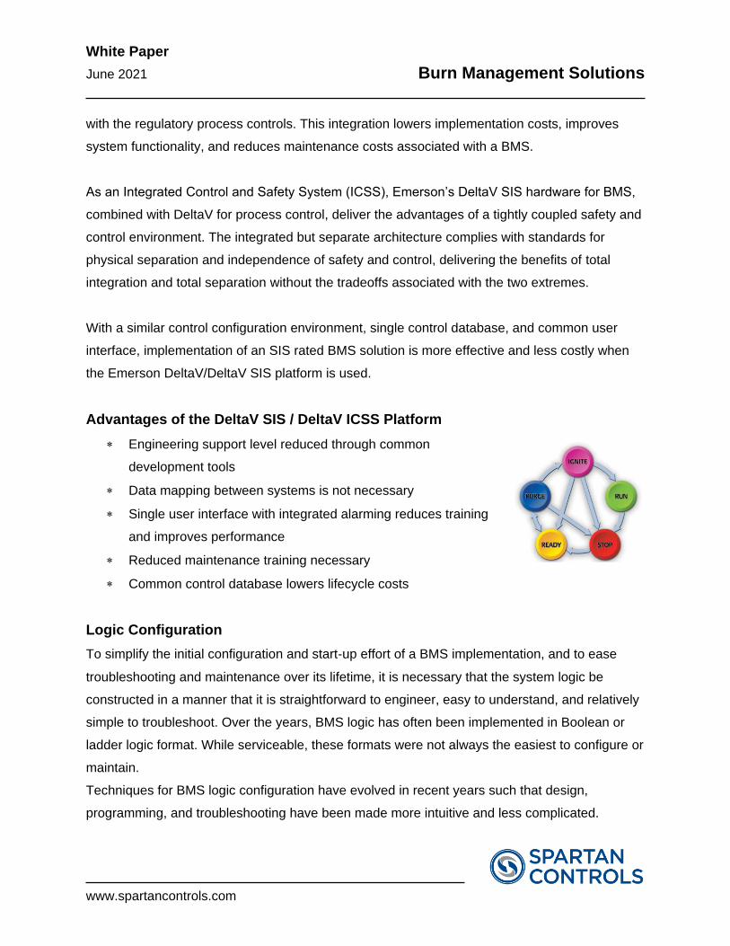
As an Integrated Control and Safety System (ICSS), Emerson’s DeltaV SIS hardware for BMS,
combined with DeltaV for process control, deliver the advantages of a tightly coupled safety and
control environment. The integrated but separate architecture complies with standards for
physical separation and independence of safety and control, delivering the benefits of total
integration and total separation without the tradeoffs associated with the two extremes.
With a similar control configuration environment, single control database, and common user
interface, implementation of an SIS rated BMS solution is more effective and less costly when
the Emerson DeltaV/DeltaV SIS platform is used.
Advantages of the DeltaV SIS / DeltaV ICSS Platform
Engineering support level reduced through common
development tools
Data mapping between systems is not necessary
Single user interface with integrated alarming reduces training
and improves performance
Reduced maintenance training necessary
Common control database lowers lifecycle costs
Logic Configuration
To simplify the initial configuration and start‐up effort of a BMS implementation, and to ease
troubleshooting and maintenance over its lifetime, it is necessary that the system logic be
constructed in a manner that it is straightforward to engineer, easy to understand, and relatively
simple to troubleshoot. Over the years, BMS logic has often been implemented in Boolean or
ladder logic format. While serviceable, these formats were not always the easiest to configure or
maintain.
Techniques for BMS logic configuration have evolved in recent years such that design,
programming, and troubleshooting have been made more intuitive and less complicated.

White Paper
June 2021 Burn Management Solutions
www.spartancontrols.com
Complex and customized Boolean or ladder programming have now been replaced by
specialized function blocks. Emerson’s DeltaV SIS logic controllers are equipped with IEC
61508‐certified function blocks particularly designed for the sequential nature of processes such
as Burner Management Systems. Spartan has developed a unique methodology for specifying
different burner states and required conditions in a simple matrix format. One page shows the
states, active trip conditions, valve positions, and how to move from state to state. Configuration
is greatly simplified.
For instance, this is an example of the configuration for a dual fuel boiler. It has 9 basic states
for a main sequence.
Each Fuel also has a simple sequence associated
with it. In this case there are three fuel sequences,
the fuel for the pilot, oil, and natural gas. Each of
these sequences is identical to each other and
generally very straightforward.
Defining how to move from one state to another is
typically clear‐cut. It can be as simple as, during the
purging state, that the transition to purge complete happens when the purge timer completes.
Each output is defined based on the state. The main block valves for the oil, for example, are
only opened when the oil sequence is in the oil light‐off or oil on states. As described next,
function blocks manage these states, the transitions, and the outputs.
Boiler Tripped (Active)
1
Waiting For Purge
Permissives
3
Purging
4
Purge Complete
5
Oil Lit
7 Pilot Lit
6
Gas Lit
8
Dual Fuel
9 2
Offline ai

White Paper
June 2021 Burn Management Solutions
www.spartancontrols.com
The following DeltaV SIS function blocks are key components used in developing a BMS
application:
State Transition Diagram
This block implements a state machine, where each burner and the overall burner process is
considered to be in one of a number of configurable states, with transitions between the states
based on identified plant conditions. The function block changes state based on the values of its
transition inputs. For example, purging, ignition, and running might all be defined states, with
specific operator inputs such as start or plant inputs such as an accumulated air flow, signifying
a change in state.
Cause and Effect Matrix
This executes interlock and permissive logic to associate inputs (causes) with outputs (effects)
to control one or more final elements. The function block includes state‐based cause masking,
and allows different trip conditions for each of the defined burner states. A first‐out trap feature
quickly identifies the root cause of any trip condition, minimizing down‐time and aiding
troubleshooting.
Step Sequencer
The step sequencer block drives a number of discrete outputs based on the current burner state
derived from the state transition block. This simplifies the logic greatly and makes checking the
configuration straightforward.
BMS implementation and maintenance is now simplified. In addition, change management can
now be more tightly controlled. DeltaV SIS change management supports regulatory
requirements and streamlines IEC 61511 compliance. All changes in DeltaV SIS system logic
may be captured based on the change, who made it, and when it was made.

White Paper
June 2021 Burn Management Solutions
www.spartancontrols.com
Operator Information
Many industrial combustion processes run for months at a time, only being shut down and
started up once or twice a year. For this reason, operations personnel may not be as familiar
with startup procedures as they are with normal operating scenarios. Traditionally, many Burner
Management Systems have not provided much assistance.
In the past, BMS implementations often did not help in startup situations because, as the
combustion process was being brought on‐line, there was not clear indication of the state of the
startup sequence.
Operations personnel often were not presented clear indication of where in the sequence the
process was and what particular interlocks were preventing the light‐off procedure to advance.
This has often resulted in start‐up delays, time consuming troubleshooting, and at times, unsafe
operating conditions. Spartan has improved the user interface for Burner Management Systems
such that clear indication of the process status is provided to operations personnel at all times.
The BMS actually assists personnel in bringing the combustion process safely on‐line.
Information is delivered both graphically and with text. At a glance, users can see exactly where
in the startup sequence the process is. If there is a permissive not met, this is indicated clearly
with a full text description.
Maintenance Information
In the same way that clear status information should be presented to operations personnel, the
maintenance staff needs access to details from the Burner Management System that will allow
quick and uncomplicated troubleshooting of any combustion process issues. Traditionally, this
has been a shortcoming in BMS installations.
White Paper
June 2021 Burn Management Solutions
www.spartancontrols.com
BMS designs of the past have often been very difficult to troubleshoot and maintain due to
limited visibility into sequence status, lack of first‐out indication, and series wiring of multiple
interlocks into a single logic controller input point.
Spartan has designed its BMS solution from the bottom‐up to be straightforward to troubleshoot
and cost effective to maintain over its lifetime. First, each required interlock is wired to a
separate logic controller input point so that it can be monitored and tracked individually. Further,
the status and health of Emerson smart devices can be checked continuously by the system so
that issues can be identified before they cause unnecessary downtime or unsafe conditions.
The function blocks in Emerson’s DeltaV SIS controllers provide first‐out information that is
simply displayed for maintenance and operations personnel with proper authority. Historical
data collection saves all of the first‐outs, authorizations, and other needed documentation. And
further, when the DeltaV SIS BMS is implemented as an ICSS with a DeltaV process control
system, interface issues between the BMS and combustion control functions are eliminated and
BMS maintenance can be done using the same tools as are used for the overall process.
Implementation Cost
Burner Management Systems are installed to prevent dangerous combustion of fuel used in
industrial combustion processes, and as such, they must be engineered rigorously and installed
properly. In addition, the BMS should be cost effective to implement, operate, and maintain in
order to support the overall business objectives of the site.
Spartan leverages multiple service and hardware capabilities in order to keep the cost of BMS
implementations down while delivering excellent system performance:
Application Experience Engineering personnel with extensive BMS experience are efficient at
delivering high quality designs and configurations

White Paper
June 2021 Burn Management Solutions
www.spartancontrols.com
Standard Templates for hardware design and logic configuration are pre‐engineered,
saving time and providing superior system functionality
Function Blocks DeltaV SIS function blocks reduce configuration effort while delivering
superior system functionality and allowing easier troubleshooting
Integrated Architecture Separate but integrated architecture of DeltaV SIS and DeltaV saves on
engineering tools, footprint, and training requirements
DeltaV SIS with Electronic Marshalling dramatically reduces engineering effort and field wiring
costs
Electronic marshalling for DeltaV SIS streamlines engineering efforts, reduces control system
footprint, and dramatically decreases field wiring.
DeltaV SIS electronic marshalling and characterization module (CHARM) technologies reduce
BMS equipment footprint and eliminate traditional marshalling cabinets. Existing field device
wiring can be connected to CHARM terminal blocks in field enclosures near those devices,
thereby reducing installation cost.
Individual CHARMs are available to connect to any I/O type, so Electronic Marshalling provides
unprecedented flexibility to easily change or expand the BMS system and allows the hardware
engineering effort to be separated from logic configuration. Re‐work and commissioning costs
are reduced by the ability to easily change I/O type and quantity in the field on a point by point
basis late in the project development cycle.
Typical Delta V BMS Architecture

White Paper
June 2021 Burn Management Solutions
www.spartancontrols.com
Emerson Meets and Beats BMS Application Challenges
With Spartan, BMS implementations are done cost effectively to meet all codes and standards
while delivering a system that makes the process easier to run and maintain. With a
combination of specialized engineering skills, pre‐engineered designs, and unique automation
system technologies, Spartan delivers solutions that meet the particular challenges of BMS
applications:
Systems are implemented in accordance with all applicable codes and standards
The BMS is considered holistically, including piping and field devices as well as the logic
controller and configuration and start up services
Logic configuration is implemented on Safety Instrumented System (SIS) hardware
Proper measurement devices and final elements are supplied as necessary
A separate but integrated hardware solution is provided when possible to cut lifecycle cost
Logic is implemented using state sequence tools to simplify understanding and ease
maintenance
Clear indication of the BMS sequence is provided to operations to aid process management
First out logs are provided for maintenance to simplify troubleshooting
Electronic marshalling is utilized to lower engineering and installation costs