Embed Size (px)
Citation preview
COMDTPUB P16700.4NVIC 5-93JULY 20, 1993
NAVIGATION AND VESSEL INSPECTION CIRCULAR NO. 5-93Electronic Version for Distribution Via the World Wide Web
Subj: GUIDANCE FOR CERTIFICATION OF PASSENGER CARRYING SUBMERSIBLES
1. PURPOSE. This circular provides guidance for certification of passenger carrying submersiblesunder Title 46, Code of Federal Regulations, Subchapter T - Small Passenger Vessels (under 100gross tons) (46 CFR Parts 175-187).
2. DIRECTIVES AFFECTED. None.
3. DISCUSSION.
a. Nonmilitary submersibles have been used for several decades in the industrial,experimental and research fields. The first successful commercial passenger carryingsubmersible was the AUGUSTE PICCARD (Switzerland, 1964-65). The first passengercarrying submersible operation in waters subject to Coast Guard jurisdiction commencedin 1987 at St. Thomas, U.S. Virgin Islands.
b. For operations under U.S. jurisdiction, the inspection statutes of U.S. Code Title 46 -Shipping (46 U.S.C.) and the regulations in 46 CFR Subchapter T - Small PassengerVessels (46 CFR Parts 175-187) apply to any submersible less than 100 gross tonscarrying more than six passengers. Since the regulations were developed primarily withsurface craft in mind, many of the requirements cannot be applied to or may otherwise beinappropriate for submersibles. Additionally, there are many measures not in theregulations which must be applied to attain an equivalent level of safety to that of surfacecraft, and otherwise minimize any inherent hazards of underwater operation.
c. There has also been much interest regarding the operation of smaller submersibles carryingsix or fewer passengers. To date, only a few such operations exist. Such vessels are notsubject to present inspection laws. However, they are subject to regulation as uninspectedvessels under 46 CFR Subchapter C - Uninspected Vessels (46 CFR Parts 24-26). Design,construction and operation must be accomplished in a safety-conscious manner due to thesignificantly greater inherent risk to passengers (compared to surface vessels) and theunique nature of the vessels. Additionally, they may be subject to special local operatingrestrictions as may be imposed by the Captain of the Port (COTP) relative to navigationsafety, port safety and security, and vessel traffic considerations. Note; At the time ofwriting of this publication, Bill H.R. 1159 was before Congress to require certification ofall submersibles carrying one or more passengers for hire.

NAVIGATION AND VESSEL INSPECTION CIRCULAR NO. 5-93
2
d. Recreational submersibles must comply with 33 CFR, Subchapter S (Boating Safety).Undocumented submersibles (i.e., those not having federal documentation) with propulsionequipment, must be numbered in accordance with the federal numbering system or thenumbering system of the state in which the submersible will be principally operated, inaddition, recreational vessels must carry a Hull Identification Number (HIN). When asubmersible is involved in a collision, accident, or casualty, the operator is required toreport such occurrences to the appropriate Officer in Charge, Marine Inspection (OCMI)or state authorities, and to render all possible assistance to others involved in suchincidents. The regulations contained in 33 CFR 155 (Oil Pollution Prevention Regulationsfor Vessels) and 33 CFR 159 (Marine Sanitation Devices) also apply to recreationalsubmersibles. Voluntary reports of recreational submersible operations in or near U.S.waters may be made to the nearest Coast Guard Operations Center. These reports areintended for informative use in search and rescue (SAR) activities only. Inquiries about theextent of such reports and other questions that cannot be resolved locally should bedirected to Commandant (G-NRS) at (commercial/FTS) 202/8-267-1948.
e. Enclosure (1) to this circular provides general guidance relative to the inspection andcertification requirements for submersibles, primarily those carrying more than sixpassengers. Enclosure (2) to this circular provides general guidance relative to the stabilityof the vessel, and enclosures (3) through (5) provide reference information. This documentdoes not stand alone, i.e., it makes reference to the applicable regulations and to theappropriate industry standards. Designers, builders and operators must also be familiarwith and use the referenced materials.
f. Submersible technology is not new, but its application in the passenger carrying industry isstill very much under study. Although we have established a safe baseline, as this industrygrows we will see many technological advances which will have to be carefully consideredin view of safety. The Coast Guard has used the results of two recent studies on passengersubmersible safety as well as in-house research in developing these guidelines. Togetherwith other recognized standards described or mentioned in enclosure (1), and until newregulations become necessary, this document is considered to be the best availableguidance to facilitate this industry while ensuring passenger safety.
g. For the purposes of this document; submersible, submarine, and sub have no difference inmeaning. All three terms are used interchangeably to describe any self-propelled vesselcarrying passengers and crew which is designed to operate on the surface, submerge,operate submerged, surface and remain afloat. Internal pressure is normally maintained ator near one atmosphere.
NAVIGATION AND VESSEL INSPECTION CIRCULAR NO. 5-93
3
4. IMPLEMENTATION. Coast Guard plan review, inspection, and certification will be based on theguidance contained in this circular. Owners, operators, designers and builders of passengercarrying submersibles must become familiar with the applicable regulations and standards. Tofacilitate a timely inspection for certification, they are also urged to closely follow the guidelines ofenclosures (1) through (6).
End: (1) Guidance for Certification of Passenger Carrying Submersibles(2) Guidelines for Stability of Small Passenger Submersibles(3) References(4) Addresses(5) Urban Mass Transportation Administration (UMTA) Recommended Fire Safety Practices
for Rail Transit Materials Selection(6) Failure Modes and Effects Analysis (FMEA)
Non-Standard Distribution:
C:e Honolulu, Puget Sound (35); Miami, Long Beach, Portland OR (25); Jacksonville (20); Anchorage(15); San Juan, Tampa, San Diego, Juneau, Valdez (10); San Francisco, Guam (5); New Orleans,Hampton Roads, Baltimore, Philadelphia, Port Arthur, Houston, Mobile, Morgan City, Boston,Portland ME, Charleston, Galveston, Louisville, Memphis, Paducah, Pittsburgh, St. Louis,Savannah, Cleveland, Buffalo, Chicago, Detroit, Duluth, Milwaukee, Providence, Huntington,Wilmington, Corpus Christi, Toledo (1).
C:m New York(S); Sturgeon Bay (4); St. Ignace (1).
D:d Except Baltimore and Moriches.
D:l CG Liaison Officer MILSEALIFTCOMD (Code N-7CG), CG Liaison Officer RSPA (DHM-22),CG Liaison Officer MARAD (MAR-742), CG Liaison Officer JUSMAGPHIL, CG LiaisonOfficer World Maritime University, CG Liaison Officer ABS (1).
ABS (24).Det Norske (1).NOAA Fleet Inspection Officer (1).U.S. Merchant Marine Academy (1).

Enclosure (1) to NVIC 5-93
i
GUIDANCE FOR CERTIFICATION OF PASSENGER CARRYING SUBMERSIBLES
TABLE OF CONTENTS
Page
Chapter 1. - General
A. Background 11. Introduction 12. The Underwater Safety Project (USP) 13. U.S. Navy 14. American Bureau of Shipping (ABS) 25. Passenger Submersible History 2
B. Applicability 31. Subchapter T - Small Passenger Vessels 32. Subchapter C - Uninspected Vessels 33. Subchapter H - Passenger Vessels 44. Recreational Submersibles 45. Foreign Flag Submersibles 4
C. Equivalency 4D. Definitions 4E. Regulation Development 4
Chapter 2. - Inspection and Certification
A. Concept Review 5B. Application for Inspection 5C. Plan Review 5D. Inspection for Initial Certification 6E. Inspection for Certification 7F. Certificate of Inspection (COI) 7G. Reinspection 7H. Drydocking or Hauling Out 8I. Notification of Repairs and Alterations 8
Chapter 3. - Construction and Arrangement
A. General Design 10B. Hull Structure 10
1. Structural Standards 112. Hull Penetrations 113. Viewports 114. Exostructure 115. Material 11
C. Subdivision and Stability 111. Subdivision 112. Stability 11
D. Means of Escape 11E. Interior Construction 11

Enclosure (1) to NVIC 5-93
ii
1. Fire Protection2. Arrangements
1112
F. Rails and Guards 13
Chapter 4. - Lifesaving Equipment
A. Life Preservers 14B. Primary Lifesaving Equipment 14C. Ring Buoys 14D. Distress Signals 14E. Emergency Position Indicating Radio Beacons (EPIRBs) 14F. First Aid Kit 14G. Individual Emergency Breathing Apparatus 14
Chapter 5. - Fire Protection Equipment
A. General 16B. Fire Pumps/Fire Main System 16C. Fixed Fire Extinguishers 16D. Portable Fire Extinguishers 16E. Fire Detection System 17
Chapter 6. - Machinery Installation
A. General 18B. Life Support Systems 18
1. General 182. Oxygen 183. CO2 Removal 184. Tests 18
C. Bilge Systems 18
Chapter 7. - Electrical Installation
A. General 19B. Cable 19C. Emergency Power 19D. Batteries and Battery Charging 19
Chapter 8. - Vessel Control
A. Ballast Systems 21B. Emergency Ballast Systems 21C. Auto-Pilot 21D. Communications 21E. Alarms 21F. Remotely Controlled Valves 21
Chapter 9. - Operations
Enclosure (1) to NVIC 5-93
iii
A. General 22B. Failure of Vital SystemsC. Dive Site
2222
D. Operations Manual 22E. Rescue 23F. Maintenance 24G. Navigation Rules 24
Chapter 10. - Manning and Licensing
A. General 25B. Submersibles Personnel Training and Qualification Requirements 25
Chapter 11. - Foreign Passenger Submersibles Operating in the U.S.
A. Coastwise Trade 27B. Inspection Standards 27
1. Reciprocity 272. SOLAS Regulations 27
C. Inspection and Certification 271. Submersibles with SOLAS Certificates 272. Submersibles without SOLAS Certificates 28
D. Operations Manual 28
Enclosure (1) to NVIC 5-93
1
CHAPTER 1. GENERAL
A. Background.
1. Introduction. Considerable research and development has been conducted relative to thesafe design, construction, and operation of small manned submersibles. Participation insuch efforts has included the Navy, the Coast Guard, the submersible industry, theAmerican Bureau of Shipping (ABS), and technical societies such as the MarineTechnology Society (MTS) and the Society of Naval Architects and Marine Engineers(SNAME). The safety of industrial and research submersible operations has been theprimary concern of most work accomplished until recently. The advent of the passengercarrying submersible has created the need to look at manned submersibles in a differentlight. Since 1986 the Coast Guard has worked closely with the developers of this newindustry to establish a sound safety policy for the design, construction, and operation ofthese new submersibles.
2. The Underwater Safety Project (USP).
a. The Coast Guard Headquarters USP was established in 1968 in reaction to whatappeared at the time to be a strong near-term need for Coast Guard regulation ofunderwater vehicles and stations. At the time there were about 50 civiliansubmersibles in existence in the U.S. In a decade of submersible operations therehad only been a few major accidents, resulting in the loss of one life. However, inthe early seventies, two separate accidents claimed three more lives, the more well-known being the Johnson Sea-Link entrapment. Therefore, to ensure that anacceptable level of safety was maintained, the Coast Guard proposed legislation toobtain authorization for regulation of nonmilitary submersibles regardless of size,service, or number of passengers.
b. Research and development efforts were initiated to determine the basicrequirements for submersible regulations. Liaison with industry and standardsorganizations was established in order to develop policy, codes, and guidelines forsubmersibles. MTS conducted three studies and published three sets of guidelinesfor submersible safety during the period from 1968 to 1979. These guidelinesaddress design, operations, personnel, maintenance, procedures, and equipment.The Coast Guard actively participated in the development of the MTS guidelinesand assisted with funding.
c. Not long after the USP was formed, the priority of the project was questioned. Theproposed legislation attempts regarding the regulation of nonmilitary submersibleshad been unsuccessful. Also, the anticipated demand for submersibles and interestin the activity had not materialized. Although there had been steady advancementof submersible technology, the maritime industry had experienced an economicrecession. The use of submersibles for other than limited industrial, experimental,or research applications did not appear likely. Coast Guard regulatory efforts onthis subject ended with the termination of the USP in the late seventies.
3. U.S. Navy. The Navy has always been concerned with the safety of military submersibles.The loss of THRESHER in 1963 caused Navy efforts to intensify and resulted in specialsafety programs. With the advent of the deep research vehicles such as TRIESTE and
Enclosure (1) to NVIC 5-93
2
ALVIN, the Navy took action to ensure the safety of Naval personnel when embarked onmanned noncombatant submersibles. Military certification requirements were applied asappropriate, and additional safety requirements were dictated by the submersible'sspecialized design and use. ALVIN was the first such submersible certificated by theNavy. The Navy's certification requirements are now published in "Systems CertificationProcedures and Criteria Manual for Deep Submergence Systems, NAVMAT P-9290."
4. American Bureau of Shipping (ABS).
a. During the mid-sixties, ABS was approached by industry representatives and bythe U.S. Navy regarding the practicality of preparing standards for the design andconstruction of commercial submersibles. Because of the limited information andexperience available in the area of commercial submersibles, ABS began a lengthyeffort of collecting, evaluating and developing technical data, safety criteria,operational aspects, etc. which led to the 1968 publication of the "Guide for theClassification of Manned Submersibles."
b. During the seventies, builders, operators, ABS, the Navy, and the Coast Guardgained extensive experience relative to small submersibles, primarily those forresearch, industrial, and experimental service. Subsequently, ABS published"Rules for Underwater Systems and Vehicles" in 1979 (ABS Rules). The CoastGuard participated in the development of these rules. While not originally intendedto encompass passenger submersibles, these rules have served as a foundation forABS to class a number of tourist submersibles to date. In 1990, ABS publishedthe “Rules for Building and Classing Underwater Vehicles, Systems, andHyperbaric Facilities” which include specific requirements for passenger carryingsubmersibles.
5. Passenger Submersible History.
a. In 1964 and 1965, the AUGUSTE PICCARD, a forty passenger submersible,took some 32,000 tourists on over 1100 dives to 300 meters in Lake Geneva at theSwiss National Exposition. Operation of the AUGUSTE PICCARD in the UnitedStates in passenger carrying service was proposed; however, the Coast Guardwould not accept the vessel because it was not built under Coast Guard inspection.The AUGUSTE PICCARD was then converted and operated as a research andindustrial submersible.
b. In 1984, a Canadian commercial submersible operating firm, Sub AquaticsDevelopment Corporation, built two passenger carrying submersibles. The vessels,ATLANTIS I and II, were designed to carry 28 passengers and two crewmen onshort voyages to a depth of 45 meters. These two vessels are now operating in theCayman Islands and Barbados. With the success of these vessels, Sub Aquaticsapproached the Coast Guard with a proposal for a 47 passenger submersible to beoperated within U.S. jurisdiction in the U.S. Virgin Islands (USVI). The CoastGuard worked closely with Sub Aquatics to define basic safety requirements.Acceptable design and operational features were established to ensure the safety ofpassengers and crew at a level equivalent to that of a small passenger vessel ofsimilar capacity. This submersible, ATLANTIS III, was certificated in July 1987and has been operating successfully in St. Thomas, USVI. In June 1988, another

Enclosure (1) to NVIC 5-93
3
company successfully certificated a similar sized submersible, LOOKINGGLASS, in St. Thomas. MARIEA I, a Panamanian flag submersible, operates inSaipan under Control Verification. More passenger submersible designers,fabricators and operators are moving into this emerging segment of the touristindustry.
B. Applicability.
1. Subchapter T - Small Passenger Vessels.
a. Vessels less than 100 gross tons which carry more than six passengers are subjectto the applicable sections of Title 46 of the Code of Federal Regulations (CFR),Subchapter T (Parts 175 through 187) - Small Passenger Vessels. Subchapter T isdivided into two subcategories: "S" and "L." "S" vessels are not more than 19.8meters in length. "L" vessels are more than 19.8 meters in length. The length of thepressure hull, not the LOA, is used in determining the applicability of SubchapterS and Subchapter T requirements. To date, all Certificated submersibles havebeen considered "S" vessels. It is this group of submersibles on which this NVICfocuses. Submersibles to which Subchapter T(L) applies, and all submersiblesdesigned to carry in excess of 49 passengers, will be considered novel and will bereviewed on a case-by-case basis by Commandant (G-MTH-4, see enclosure (4)).Compliance with applicable sections of 46 CFR Subchapter S -Subdivision andStability, 46 CFR Subchapter B -Merchant Marine Officers and Seaman, 33 CFRPart 155 - Oil Pollution Prevention Regulations for Vessels, and 33 CFR Part 159- Marine Sanitation Devices, is also required.
b. In addition, due to the hazardous nature of operating a submersible vessel, theCaptain of the Port (COTP) may impose special operational requirements underthe authority of the Ports and Waterways Safety Act (33 U.S.C. 1221, et. seq.)(PWSA) for port, waterway or vessel safety concerns, or under the Magnuson Act(50 U.S.C. 191, et. seq.) for security concerns. The cognizant COTP must becontacted well in advance of any intended operations.
2. Subchapter C - Uninspected Vessels.
a. Submersibles carrying six or less passengers, are "uninspected vessels" as definedby 46 U.S.C. 2101(42). Although not subject to inspection, these vessels mustmeet the requirements of 46 CFR Subchapter C - Uninspected Vessels. They mustalso meet the applicable requirements of 33 CFR Part 155 -Oil PollutionPrevention Regulations for Vessels, 33 CFR Part 159 - Marine SanitationDevices, 33 CFR Subchapter S - Boating Safety, and 46 CFR Part 15 -ManningRequirements.
b. Because of the unique design and operating characteristics, as well as the inherenthazards of underwater operation, an uninspected submersible may be permitted inU.S. passenger operations only if it is designed and constructed to a recognizedindustry standard. Additionally, the COTP may establish special local operatingrestrictions under the authority of the PWSA or the Magnuson Act describedabove. These restrictions will address local navigation safety, port safety andsecurity, and vessel traffic considerations. To avoid delayed operations due to

Enclosure (1) to NVIC 5-93
4
safety concerns that may be raised about the design and construction of the vesselor its intended operating area, an operator should contact the cognizant COTPwell in advance of any intended operations.
[Note: At the time of writing of this publication, Bill H.R. 1159 was before Congress torequire certification of all submersibles carrying one or more passengers for hire.]
3. Subchapter H - Passenger Vessels. Any passenger carrying submersible that is 100 grosstons or more would be subject to inspection under 46 CFR Subchapter H. Althoughsubmersibles of this size are not envisioned for the near future, the guidelines of thiscircular could be used subject to application of Subchapter H instead of Subchapter T.
4. Recreational Submersibles. Recreational vessels, as defined in 46 U.S.C. 2101(25), arevessels manufactured or operated primarily for pleasure, or leased, rented, or chartered toanother for the latter's pleasure. Submersibles within this category are subject to therequirements of 33 CFR Subchapter S - Boating Safety, Parts 173-183. The guidelines inthis circular generally do not apply; however, depending on the area of operation, COTPoperating restrictions may be appropriate. This will be evaluated on a case-by-case basis.These guidelines may be of assistance to a manufacturer or owner of a recreationalsubmersible.
5. Foreign Flag Submersibles. See Chapter 11.
C. Equivalency. This NVIC is intended to outline a basis for determining equivalency of passengercarrying submersibles to conventional small passenger vessels. Since the applicable regulations weredeveloped primarily with surface craft in mind, many specific features cannot be applied to or mayotherwise be inappropriate for a submersible. The Coast Guard's approach to the novel design and uniqueoperational hazards of passenger submersibles is to require a level of safety equivalent to that required fora surface craft of similar size and service. This is established in part through a combination of designrequirements and operational restrictions. A written operations manual detailing normal and emergencyoperational procedures should be prepared early in the planning stage and submitted to CommandingOfficer, Marine Safety Center (MSC; see enclosure (4)) for review. It will be evaluated in conjunction withthe proposed design to ensure the project addresses crew training, operational parameters, surface vesselcontrol, and safety features.
D. Definitions.
1. Design Depth - maximum depth for which a system or vehicle is designed.
2. Rated Depth - The maximum depth reached during a manned test dive witnessed by aninspector or an ABS surveyor, as may be accepted by the OCMI. The rated depth may notexceed the design depth
3. Operating Depth - Depth at which the vessel normally operates. The operating depth maynot exceed the rated depth of the vessel.
E. Regulation Development. As more experience is gained with passenger carrying submersibles,regulations specific to them and to their operations will be promulgated. Therefore, comments toimprove this NVIC are solicited. Comments should be submitted to Commandant (G-MTH-4, seeenclosure (4)).
Enclosure (1) to NVIC 5-93
5
CHAPTER 2. INSPECTION AND CERTIFICATION
A. Concept Review. Concept review of submersibles will not be required for vessels which generallycomply with the guidelines in this circular. All operations manuals and vessel designs must beapproved by the Commanding Officer, MSC (see enclosure (4)). If the vessel incorporates novelfeatures outside the scope of the guidance herein (i.e., if the vessel is in excess of 19.8 meters inlength, has a pressure hull of a design other than that permitted by the American Society ofMechanical Engineers (ASME), carries in excess of 49 passengers, engages in operations otherthan that described in this circular, etc.), the proposal, or portions thereof, will be forwarded by theMSC to Commandant (G-MTH-4) for concept review.
B. Application for Inspection. An Application for Inspection (CG-3752) should be submitted to theOfficer in Charge, Marine Inspection (OCMI) having responsibility for the location where thevessel will be built. Contact should also be made with the OCMI having jurisdiction in theproposed operating area. See enclosure (4).
C. Plan Review.
1. Detailed plan review will be done by the MSC (see enclosure (4)). Plan submittalprocedures should be discussed with the cognizant OCMI(s) as well. Detailed plan reviewwill not normally be performed before jurisdiction (evidence that Coast Guard inspection isrequired) has been established and substantial evidence (e.g., a contract) is provided thatthe submersible will, in fact, be constructed. If the vessel incorporates novel features,conceptual plan review, as noted in Section 2.A above, may be performed by Commandant(G-MTH4, see enclosure (4)), prior to substantiating intent to construct.
2. In addition to the plans noted in Subchapter T, the following will be required for detailedplan review:
a. Pressure hull strength calculations and construction tolerances including those for:viewports, hatches, joint details, penetrations, attachments, and methods ofattachment.
b. Life support systems/equipment, material specifications (as appropriate), andsupporting calculations for:
(1) Carbon dioxide removal
(2) Oxygen supply
(3) Emergency breathing
(4) Sensors and monitoring equipment
c. Fire protection systems/equipment.
d. Bilge system.
e. Ballast system plans and calculations.

Enclosure (1) to NVIC 5-93
6
f. weight, stability and buoyancy data and calculations. Both a surface and asubmerged inclining experiment will be required. A proposed procedure for thesetwo inclinings must be submitted to G-MSC (see enclosure (4)).
g. Calculations which demonstrate adequate buoyancy and stability to permit thevessel to surface in a timely manner, while maintaining an upright attitude, afterreceiving damage to any ballast/buoyancy tanks. Underwater escape and rescuefrom a submerged submersible is not likely to be successful and in any event itwill be difficult and hazardous. Therefore, all means for returning the submersibleto the surface in both the normal and emergency modes should be detailed.
h. Intact and damage freeboard and limits of heel/trim calculations. Access tolifesaving equipment and means of exiting the submersible once on the surfacemay be difficult. Adequate freeboard and stability must be available on the surfaceto permit the safe disembarkation of passengers under the worst expected surfaceconditions in the designated operating area. Compliance with ABS rule 3.19.1 willnormally satisfy this requirement.
i. Power system and battery charging plans.
j. Control systems plans and layout, including maneuvering, navigation, life support,and communication systems.
k. Detection systems for hydrogen and chlorine gas generation.
1. Quality control and testing procedures.
m. Material identification.
n. Failure modes and effects analysis. See enclosure (6) for guidance.
D. Inspection for Initial Certification.
1. The basic inspection and certification requirements are contained in Subchapter T.Inspection for certification is normally conducted only on U.S. flag vessels; however,exceptions to this are discussed below. Coast Guard inspections during construction mustbe scheduled with the OCMI. Sea trials will be required as part of the initial certificationin order to prove all of the vessel's systems. Construction of the vessel should not beginuntil all required plans have been approved. Owners who choose to build on speculation,prior to plan approval, do so at their own risk.
2. For a U.S. flag vessel built overseas, the ultimate aim will be a degree of inspection duringconstruction equivalent to that which would be attained if the vessel were built in the U.S.The Coast Guard maintains only a limited number of inspectors overseas, hence overseasinspections may be complicated by delays in communications and inspector availability.Additionally, the travel and subsistence costs associated with overseas inspections arereimbursable from the owner to the Coast Guard. See NVIC 11-84 for further guidance onforeign construction requirements relative to the construction of U.S. vessels overseas.
Enclosure (1) to NVIC 5-93
7
3. Although the ABS Rules have been recognized in part, the presence of an ABS surveyordoes not substitute for the presence of a Coast Guard inspector. A Coast Guard inspectorwill be present during various phases of construction and will witness all tests, except asthe OCMI may allow otherwise.
E. Inspection for Certification. The requirements in 46 CFR Part 176 concerning periodic inspectionfor certification and reinspection apply. Except as may be allowed by the OCMI, a Coast Guardinspector must be present to inspect the vessel and witness all required tests. During periodicinspections for certification, in addition to the inspections required under Subchapter T, theinspector will:
1. Be guided by 46 CFR 197.462 pressure vessels and pressure piping (Commercial DivingOperations) and Sections 7, 12 and 13 (Surveys after Construction) of the ABS Rules, inparticular rule 13.17 through 13.21;
2. Normally witness a test dive (see ABS rule 3.13) to the design depth (maximum depth forwhich a system or vehicle is designed) during which all systems are to be operationallytested [Note: If the sub is tested to a depth less than the design depth, the rated depth of thesub will be limited accordingly.];
3. Review maintenance records to ascertain the nature and extent of routine maintenance;
4. Ensure that all monitoring instruments and gauges, particularly those in the life supportsystems, are calibrated; and
5. Examine the internal surface of the pressure hull in select locations to ensure the absenceof corrosion or internal damage; review the results of dimensional checks to verify thegeometric integrity of the pressure hull. These checks should be performed triennially.
F. Certificate of Inspection (COI) A submersible will be certificated for a specific operation and aspecific dive site. The dive site must be specified on the COI. If support vessels are integral to thesafe operation of the submersible they should also be referenced on the COI with any operatingrestrictions regarding the support vessel's duties with respect to the submersible's safety. Themaximum duration of an operational dive will be specified on the COI. The COI should alsoreference the operations manual. The requirements of section 12 of the ABS Rules shall also beconsidered.
G. Reinspection. Reinspections will be conducted annually as required by 46 CFR Subchapter T andguided by ABS rule 13.17 through 13.21. Except as may be allowed by the OCMI, a Coast Guardinspector will be present to inspect the vessel and witness all required tests. Emphasis will be givento emergency equipment, and the operation of all vessel control and life support systems.
1. A visual examination of the hull, both internally and externally, should be conductedinsofar as it is practicable.
2. Maintenance records should be reviewed by the inspector to ascertain the nature and extentof routine maintenance.
3. All monitoring instruments and gauges, particularly those in the life support systems,should be calibrated and proven functional.

Enclosure (1) to NVIC 5-93
8
4. An operational dive, which need not be to the rated depth, should be conducted and allsystems operationally tested. (The maximum depth reached during a manned test divewitnessed by an inspector or an ABS surveyor, as may be accepted by the OCMI. Therated depth may not exceed the design depth.)
5. Pilot evaluation.
H. Drydocking or Hauling Out.
1. Submersibles shall be drydocked or hauled-out at intervals not to exceed 18 months. Theperiodic examination requirements specified in 46 CFR 197.462 for commercial divingequipment and Section 13 of the ABS Rules, Surveys after Construction, should be usedas a guide during drydock examinations. Attention is called to the need to checkdimensional tolerances and is described in further detail in ABS rules 13.19.2.f. andsection 5. Underwater surveys in lieu of an actual drydocking or haul-out are notconsidered an acceptable alternative for submersibles. The condition of externally mountedballast tanks, high pressure air tanks and 02 bottles, hydraulic and electrical systems mustbe given special attention. Additionally, care should be taken to determine if the pressurehull has sustained any damage which will require repair. External stiffeners and hullpenetrations shall be checked carefully for evidence of fatigue cracking. Generally, theCoast Guard will adopt a very conservative approach regarding repairs to the hull, lifesupport systems, and buoyancy/ballast systems. Full restoration will be required.Approved welding procedures and non-destructive testing will be required on all pressurehull repairs.
2. Viewports have a limited number of dive cycles before fatigue failure becomes a concern.The ASME PVHO-1 Code limits viewports to 10,000 pressure cycles or a design life of10 or 20 years (depending on the type of loading) after the date of manufacture, whichevercomes first. Alternatively, the operator may implement a testing program in accordancewith the PVHO-1 code to empirically prove the cycle life of the viewport design over101000 cycles. Each dive imparts some deformation to the hull and viewports. Therefore,each dive must be recorded as one pressure cycle, or 10,000 dives are equal to 10,000pressure cycles. Operators wishing to extend the cycle life of their viewports throughtesting must contact Commandant (G-MTH-2, see enclosure (4)) for approval of thetesting procedures. In any case, viewports must be replaced at the end of their design life.The design life is the lesser of the PVHO-1 Code requirement or the manufacturer'srecommendation. Viewports should be visually inspected by the operator daily for evidenceof failure. The window (the acrylic inside the viewport frame) supplier must identify thewindow in accordance with the PVHO Code. The owner is responsible for tracking eachviewport's pressure cycles and time in service. See section 2.1 below regardingreplacement or repair of damaged viewports.
I. Notification of Repairs and Alterations.
1. Notification must be given to the OCMI before any repair or modification is made to thevessel. Additionally, no modifications or alterations shall be made to the pressure hull orany life support systems without consulting the MSC (see enclosure (4)).
Enclosure (1) to NVIC 5-93
9
2. Until evidence is presented to the contrary, viewports exhibiting crazing, cracking, orpermanent visible deformation are considered failed, and will be cause for their immediatereplacement. All viewport failures must be reported to the local OCMI and Commandant(G-MTH-4, see enclosure (4)).
3. Notification of any casualty must be given to the nearest OCMI, in accordance with 46 CFR 4.05.Because of the unique nature of submersibles, the definition of seaworthiness includes, but is not limited to:increase in CO, CO2 or H2 beyond the design limits, or any emergency surfacing evolution for any reason.

Enclosure (1) to NVIC 5-93
10
CHAPTER 3. CONSTRUCTION AND ARRANGEMENT
A. General Design.
1. The basic requirement for passenger submersible design is that in the event of any singlecasualty the vessel can be returned to the surface without external assistance. Backups ofsystems and equipment are essential in order to meet this general design requirement. Vitalsystems, such as those necessary for the vessel to surface, to deploy lifesaving equipment,to disembark personnel, or for life support must be shown to have an acceptable level ofreliability, a manual override control, or redundancy. On surface vessels we consider thatmost failure scenarios occur with a single casualty. However, because of the uniqueoperating conditions under which a submersible operates, some safety equipment andmeasures have been required based on the assumption that more than one failure mayoccur in a single incident. Similarly, other equipment has been required to preservehabitability in the event the submersible cannot surface.
2. Positive buoyancy in all operating modes is required so that if power or some other criticalsystem is lost the vessel will return to the surface naturally (automatically). Verticalthrusters can be used for maintaining the desired depth when operating with positivebuoyancy. In the event the vessel cannot return to the surface on its own and sinks to thebottom, the depth of water at the dive site cannot exceed the rated depth (The maximumdepth reached during a manned test dive witnessed by an inspector or an ABS surveyor, asmay be accepted by the OCMI. This may not exceed the design depth.) of the submersible.Certification of the submersible is based on the safety of the overall operation including thedive site, support vessels, proximity of rescue/salvage services, crewing, and documentedoperations manual.
B. Hull Structure.
1. Structural Standards. The hull structure should be designed, fabricated, and inspected tothe standards of the American Society of Mechanical Engineers (ASME) Code forPressure Vessels for Human Occupancy (PVHO-1). A hull structure designed, fabricated,and inspected to the standards of the ABS Rules for Underwater Vehicles Systems, andHyperbaric Facilities, is considered to provide an equivalent level of safety to ASMEPVHO-1. A proposal to use other established standards for underwater vehicles may besubmitted to Commandant (G-MTH-4, see enclosure (4)) for consideration. The standardused and the pertinent design parameters, such as design depth (maximum depth equivalentto the maximum pressure to which the vessel is designed) and structural safety factor,must be identified in the plan submittal. If the design deviates from the written standards inany manner, this must be approved by the Commandant prior to sending the plans to theMSC for plan review.
2. Hull Penetrations. Requirements for hull penetrations for hatches, viewports, fluid piping,and electrical cable are found in the ABS Rules and the ASME PVHO-1 standards.Details of such penetrations must be carefully designed as their failure could becatastrophic. Special attention should be given to clusters of penetrations to ensure
adequate ligament strength and stress relief are provided. The potential '1zipper effect" dueto placing viewports or other penetrations in line should be investigated and appropriatereinforcement provided.
Enclosure (1) to NVIC 5-93
11
3. Viewports. The only recognized standard for acrylic viewports is ASME PVHO-1. Theviewports must be adequately protected, e.g., protective covers or guards on the exteriorand interior to protect them from impact, scratching or chemical cleaning agents, keepingin mind that damaged viewports must be replaced.
4. Exostructure An exostructure should be provided to protect the pressure hull andviewports from damage due to collision, grounding, mooring, waves, or other hull impactforces. The exostructure should incorporate features to heighten the vessel's visibility whileon the surface to reduce the possibility of collision.
5. Material. If material other than that specified in PVHO1 will be used in construction of thepressure vessel, early discussions with Commandant (G-MTH-4, see enclosure (4)) will benecessary. Fatigue testing will be required. Additional testing, the extent of which will bedependent on the material to be used, may also be required.
C. Subdivision and Stability.
1. Subdivision. Subdivision is not normally required for vessels that carry 49 passengers orless and whose pressure hulls are less than 19.8 meters in length when operating inprotected waters with sufficient surface support to prevent collisions. Vessels that willcarry more than 49 passengers will be addressed by Commandant (G-MTH-4, seeenclosure (4)) on a case-by-case basis.
2. Stability. See enclosure (2) for guidance on stability.
D. Means of Escape. Two means of escape from the pressure hull are required by 46 CFR 177.15-1.Practically, this means that two hatches are required and must be arranged so that if one is notaccessible due to fire or excessive trim, the other is. Ladders may be collapsible but must be easilyrestored to the exiting position.
E. Interior Construction.
1. Fire Protection.
a. 46 CFR 177.10-5 states that the "...general construction of the vessel shall be suchas to minimize fire hazards insofar as reasonable and practicable." This meansthat a designer or builder should minimize the amount of flame, smoke, and toxicgas producing materials within the submersible to reduce the risk to passengersand crew. This is critical in a confined area, where return to the surface may taketime. The following materials have been identified as meeting the intent of theregulation:
(1) Materials approved by the Coast Guard under 46 CFR Part 164 -Materials.
(2) Materials meeting the Urban Mass Transportation Administration(UMTA) Recommended Fire Safety Practices for Rail Transit MaterialsSelection (see enclosure (5)), except that for the ASTM E662 the value ofDs must not exceed 100, and that the critical radiant flux (CRF{ for floorcoverings must not be less than 0.8 w/cm2
Enclosure (1) to NVIC 5-93
12
b. The following materials have been identified as meeting the intent of the regulationif they also meet the applicable UMTA recommended smoke density criteria (seeenclosure (5)):
(1) Fire retardant polyester resins and gel coats meeting MilitarySpecification MIL-R-21607.
(2) Polyester resins with a flame spread of 25 or less when tested to ASTMStandard E-84.
(3) Flammable gel coats not exceeding .035" in thickness.
(4) Materials approved by the Federal Aviation Administration (FAA) for theinteriors of commuter or transport aircraft in accordance with FederalAviation Regulations (FARs) 14 CFR Part 23, Appendix F, and Part 25,Appendix F, respectively.
c. Many test specifications including those referenced above have been promulgatedby various organizations for the purpose of determining the properties of materialsin response to heat and flame. Such tests are performed under controlledlaboratory conditions and may not adequately indicate how a material or productwill behave in an actual fire. Toxic gas production of plastic material in fires is ofgreat concern to fire protection engineers in all fields of public transportation.Ideally, fire risk assessments should be performed in the selection of passengercompartment materials, but practical methods have not been adequately evaluatedto allow the Coast Guard to prescribe a particular method for use by designers ofsubmersibles. However, the Coast Guard does not want to discourage the use anddevelopment of fire risk assessments and will consider such assessments formeeting the intent of 46 CFR 177.10-5(a) if carried out in a professional andcompetent manner.
d. Material for the construction of panels and enclosures that contain electricalequipment must be noncombustible and meet Underwriters Laboratory (UL) 67,panelboards, and UL 50, cabinets and boxes. Glass reinforced and thermoformedplastics will not meet these requirements. However, the use of these materials inthe pilot's control station is subject to the guidelines for interior constructionmaterials outlined above. They should not be used in the machinery space which isthe most likely source of fire on the vessel.
2. Arrangements.
a. Sufficient means of separation (e.g., a partition) between the control area and thepassenger area to prevent passengers from interfering with operator performanceshould be provided. Arrangements must be satisfactory to the cognizant OCMI.
b. Machinery spaces must be separated from the passenger space by solid partitionsand access doors must be closed during passenger operations. Machinery spacepartitions must be of an approved noncombustible material.

Enclosure (1) to NVIC 5-93
13
c. Access to escape hatches must be unimpeded.
d. Aisle width and headroom should be adequate for average sized persons standingupright, subject to the OCMI's approval.
F. Rails and Guards.
1. Studies have indicated that the most dangerous activity during normal operations of thesubmersible is the transfer of passengers between the submarine and the ferry boat. Railsas required by 46 CFR 177.35-1(h) must be installed on the deck perimeter for passengerand crew safety. Alternate arrangements must be to the satisfaction of the cognizantOCMI.
2. The means of boarding from a passenger transfer vessel must be substantial andincorporate side rails. The transfer of passengers should take into account the relative deckheights of the submersible and surface craft, differing roll periods, wave effects, andprotection of submersible appurtenances and the hull of the transfer craft. Thearrangement must be to the satisfaction of the cognizant OCMI.
Enclosure (1) to NVIC 5-93
14
CHAPTER 4. LIFESAVING EQUIPMENT
A. Life Preservers. Coast Guard approved personal flotation devices, PFDs, will be required foreveryone on board, including appropriate sizes for children. Type I PFDs may not be appropriatewhen the only escape routes are through small vertical hatches. Therefore, their use shall be subjectto the approval of the cognizant OCMI. Use of approved inflatable PFDs is appropriate andencouraged on submersibles. PFDs must be stowed on board. However, due to the apparent lack of
a significant supply of Coast Guard approved inflatable PFDs and subject to the OCMI1sacceptance, similar FAA approved (meeting TSO-C13) inflatable PFDs may be used untiladequate supplies of Coast Guard approved devices are available. Use of the FAA approveddevices requires they be serviced at least annually and be maintained to the satisfaction of theOCMI.
B. Primary Lifesaving Equipment. Generally, primary lifesaving equipment must be provided asrequired by Subchapter T. However, there are obvious problems with on board stowage ofliferafts, lifefloats and buoyant apparatus. Alternatives to on-board stowage, such as stowage onthe surface support craft, must be addressed in the operations manual and are subject to theOCMI's approval.
C. Ring Buoys. Although permanent stowage of ring buoys on the deck of the submersible may beimpractical, they must be readily available during passenger boarding or whenever personnel areon deck, unless the operations manual requires that PFDs be worn during these situations. Stowagearrangements must be addressed in the operations manual and are subject to the OCMI's approval.
D. Distress Signals. Pyrotechnics are not to be stowed inside the submersible. Means of alertingsurface craft to underwater distress situations must be addressed in the operations manual.Consideration should be given to any reliable means of signaling the surface support craft; thesignaling method must not be incapacitated by loss of primary power. The surface craft must haveVHF capability to relay distress information to search and rescue (SAR) stations and other rescueresources. If the submersible is capable of performing night dives, the means of signaling thesurface craft must be visible at night.
E. Emergency Position Indicating Radio Beacons (EPIRBs). Since submersible operations are limitedto specific dive sites, and they are required to have a surface support craft in attendance at alltimes, EPIRBs will not normally be necessary. However, the OCMI may require an EPIRB if inhis opinion one is necessary for the safety of the operation. In any case, surface craft must becapable of rapidly determining the exact location of the submersible in an emergency. Water depthand clarity are obvious factors. Nighttime operations would require a more positive means, e.g.,marker buoys.
F. First Aid Kit. A first aid kit should be provided. Since on-board injuries to passengers would mostlikely be minor, a kit approved under 46 CFR 160.041 is considered adequate. Other kits havingessentially the same contents as the approved kits will also be satisfactory.
G. Individual Emergency Breathing Apparatus.
1. Emergency life support shall be provided in the case of failure of primary systems.Compliance with ABS rule 8.21 or an equivalent arrangement will be accepted such asredundant breathing gas supply and CO2 removal systems with individual protection from
Enclosure (1) to NVIC 5-93
15
the contaminants of a fire for each person on board. The operator should be provided withan individual breathing gas mask.
2. Gas masks, self contained breathing apparatuses (SCBAs), and supplied-air respirators foruse on Coast Guard certificated vessels must meet the standards of the Mine Safety andHealth Administration (30 CFR Part 11). The equipment's performance must be certifiedby the National Institute of Occupational Safety and Health, Department of Health andHuman Services, or a Nationally Recognized Testing Laboratory such as UnderwritersLaboratories, the Canadian Standards Association, or Factory Mutual ResearchCorporation. The Coast Guard will accept SCBAs that are properly certified for a servicetime (as defined in 30 CFR 11) of at least 1 hour, provided that:
a. All passengers can be sufficiently indoctrinated in the use of the equipment with asimple oral briefing (i.e., actual donning of the apparatus is not necessary forfamiliarization).
b. The device can be used by all passengers and crew on board (i.e., adults, children,those with facial hair, etc.) without presenting the face-fit problems inherent withfull face masks.
Enclosure (1) to NVIC 5-93
16
CHAPTER 5. FIRE PROTECTION EQUIPMENT
A. General.
1. The operations manual should contain procedures for fire fighting. Fires will most likelyresult from electrical system failures. The first step in combating fires of this nature shouldbe to secure the electrical power to the affected equipment.
2. Smoking is prohibited in the submersible. Flammable materials, particularly lighters andsimilar items, are not permitted. Passengers must be informed of such restrictions.
3. All certificated submersibles thus far have fixed Halon 1301 systems. While notspecifically required by Subchapter T, the presence of such Coast Guard-approved fixedsystems is encouraged. The presence of acceptable portable extinguishers is still required.
4. Due to environmental concerns, the International Maritime organization (IMO) has madethe determination that there is no use of halon that is considered essential. EffectiveOctober 1, 1994, new halon installations aboard SOLAS certificated vessels will beprohibited. Since the production of halons is scheduled to be reduced to 50% of the 1990level by 1994 and stopped prior to 2000, commercial conditions would most likely governthe phasing out of existing halon installations, thereby possibly making the purchase ofhalon extremely expensive. IMO is also considering setting a target date for the removal ofall existing halon installations from ships. Future domestic requirements could result inprohibition of the use of halon aboard U.S. vessels not engaged in international trade.
B. Fire Pump/Fire Main System If a fire pump/fire main is provided, the source of water and itsconductivity should be considered in light of the fact that the fire is likely to be electrical in nature.
C. Fixed Fire Extinguishers. Fixed systems, if provided, must be nontoxic and nonasphyxiating CO isconsidered to be asphyxiating in an enclosed space and is not permitted. Halon 1301 is acceptable,but the system must be Coast Guard approved. Fixed Halon systems must be designed using theguidance provided in NVIC 6-72 change 1.
D. Portable Fire Extinguishers. At least two approved portable extinguishers must be provided and beeasily accessible. Halon 1301 and 1211 portable units are acceptable. If halon portable units areinstalled, they shall be Coast Guard approved and meet the minimum confined space criteria on thedevice's label (see UL 1093). The size of the units must be based on the requirements forSubchapter T. However, in the accommodation areas, consideration may be made to replace a B-IIextinguisher with two B-I extinguishers if the configuration of the space is such that larger unitswould not be appropriate. The smaller units are not as effective as the larger ones, but themaneuverability for actually fighting the fire will outweigh this. If a fixed fire suppression systemis installed, only two B-I extinguishers need be installed, one forward and one aft, which are easilyaccessible by a crew member. Consideration should be given to the concentration of halon insidethe submersible should both the portable extinguishers and fixed halon system be discharged. CO2
is not acceptable because it is asphyxiating in enclosed spaces. Dry chemical extinguishers may notbe the best choice of portable units if a substantial portion of the vessel's electrical installation isbehind interior panels.
E. Fire Detection System. Detectors should be installed for normally closed spaces containingelectrical equipment or machinery. If fire detectors are installed they must be listed by a nationally
Enclosure (1) to NVIC 5-93
17
recognized testing laboratory (NRTL) acceptable to the Commandant. If a detection system isinstalled, the components must be so listed and the system arrangement plan must be approved bythe Coast Guard's Marine Safety Center. For testing laboratories acceptable to the Coast Guardsee NVIC 2-89, Guide for Electrical Installations On Merchant Vessels and Mobile OffshoreDrilling Units. Secondary power for fire detection systems should be supplied by the emergencypower source or by batteries that have the capacity to operate the detectors for at least twice themaximum intended duration of an operational dive, or two hours, whichever is longer.
Enclosure (1) to NVIC 5-93
18
CHAPTER 6. MACHINERY INSTALLATION
A. General. Marine engineering systems are subject to the requirements of 46 CFR Subchapter T andSubchapter F as appropriate. The following are certain specific items which must be consideredand addressed in the design; however, this list is not all-inclusive.
1. Pressure vessels (other than the main hull) which are permanently installed on board thevessel are subject to 46 CFR 54.01-5. Portable pressure vessels for use on board, butserviced/refilled ashore and remaining in commerce, are considered ship's stores and mustbe Department of Transportation (DOT) approved (46 CFR 147.04). DOT cylinders thathave been modified are no longer considered DOT approved and must be shown to beequivalent to the appropriate pressure vessel standards.
2. Hydraulic and pneumatic systems must meet 46 CFR 58.30.
3. Air conditioning systems must meet 46 CFR 58.20.
B. Life Support Systems.
1. General. The standards discussed in section 8 of ABS Rules regarding oxygen supply COremoval, and emergency life support are generally acceptable. Provisions for personnelprotection from hazards such as smoke or toxic vapors during the time it takes to surfaceand evacuate should be made. Life support systems should be capable of sustaining a fullpassenger and crew load for 72 hours beyond normal operations. Supporting calculationsdemonstrating compliance with these or similar standards must be submitted. Proposals foruse of standards other than those in the ABS Rules must be submitted to Commandant (G-MTH) for evaluation.
2. Oxygen. The O2 system should be designed to maintain the O2 content at about 21 percentby volume. The O2 content should not exceed 22 percent by volume, nor should it fallbelow 19.8 percent. The system must be adequately monitored.
3. CO2 Removal. The CO removal system must be capable of maintaining the CO2
concentration at or below 0.5 percent by volume. This system must be adequatelymonitored.
4. Tests. An initial test of the CO removal system and the oxygen system should beconducted with the full passenger and crew load on board. The equilibrium point of CO2
concentration, once achieved, should be maintained for a period equal to the longestanticipated dive or one hour, whichever is longer. If the CO2 concentration exceeds 0.5percent by volume or equilibrium cannot be maintained during this period, the system isnot acceptable. The O2 supply and CO2 removal systems are among the operationalSystems that should be tested annually (see section H of chapter 2).
C. Bilge Systems. A bilge system is normally required. An acceptable alternative is a bilge water levelsensing system provided an ample capability to quickly return to the surface is available uponactivation of the sensing system alarm. A de-watering capability is required when the vessel is onthe surface. A hand operated pump may be sufficient for this purpose.
Enclosure (1) to NVIC 5-93
19
CHAPTER 7. ELECTRICAL INSTALLATION
A. General. In general, the electrical systems must meet the requirements of 46 CFR Subchapter T,Part 183 and Subchapter J - Electrical Engineering, Parts 110 - 113 as appropriate depending onwhether the vessel will be certificated as a Subchapter T or Subchapter H vessel. Systemredundancy must be considered and addressed.
B. Cable. All cable, on the low pressure side. of the hull, must meet one of the following fire teststandards: IEEE VW-1, IEEE 1202, or IEC 332-3 Category A. The fire test standard used toqualify the cable must be identified. In addition, because of the confined area of the submersible,any amount of smoke may be extremely asphyxiating, irritating to the eyes, and could cause panicor disorientation among the passengers. For this reason, all power and lighting cable must be lowsmoke, low/zero halogen cables. Types LSX or LSE cable manufactured to IEEE Standard 45(Draft, October 20, 1992), meeting the appropriate flame tests are acceptable. All enclosures ofcable, on the high pressure side, must be Nation Electrical Manufacturers Association (NEMA)rated 70 or greater, or equivalent. Signal and communication cables must meet the requirements of46 CFR 111.60.
[Note: Limited runs of water-blocked submarine cable connecting external electrical equipment tointernal junction boxes or power supplies may be acceptable, and will be reviewed on a case bycase basis by the Marine Safety Center.]
C. Emergency Power.
1. An emergency power source and controls must be provided for emergency lighting,emergency recovery systems, emergency life support systems, and underwatercommunications systems. It must be independent of the main power source and must besized to supply all connected loads for at least twice the maximum intended duration of anoperational dive. At the end of this period the voltage of the battery must not be less than88 per cent of the nominal battery voltage.
2. Emergency lighting must be automatically activated upon loss of the main power source.Pilot controls should be illuminated by the emergency lighting system. Emergency lightsmay have a means to turn them off to conserve power, but such means should not beaccessible to the passengers.
3. There must be a means to indicate low potential on the emergency batteries
D. Batteries and Battery Charging.
1. All batteries must be protected from salt water contamination, yet remain accessible forregular servicing.
2. Batteries may be installed within the vessel hull if suitable precautions are made to protectthe passenger compartment from outgassing and other associated hazards. Batterycompartment isolation and sealing, monitoring of hydrogen and chlorine gas levels,catalytic conversion of gas emissions, and automatic bilge pumping are precautions thatshould be considered. Battery compartments must be made gas tight during normalpassenger operations.
Enclosure (1) to NVIC 5-93
20
3. Battery charging procedures and equipment must be addressed from the standpoint ofhydrogen generation and sources of ignition. Battery charging should be accomplished onlywhile the submersible is at the surface, and no passengers are on board. Adequateventilation must be provided during charging operations. The ventilation system mustexhaust outside the submersible to the weather. Portable venting arrangements would beadequate.
Enclosure (1) to NVIC 5-93
21
CHAPTER 8. VESSEL CONTROL
A. Ballast Systems. Ballast systems must be designed to enable the vessel to be sufficiently stable onthe surface and have adequate freeboard for the safe transfer of passengers to and from the vesselin the worst expected operational sea state. Adequate capability of maintaining heel, trim and depthcontrol while submerged must be provided. Positive buoyancy should be maintained at all timeswith depth maintained by vertical thrusters. "Hard ballast" or pressurized water ballast tanks mustcomply with the regulations for pressure vessels, 46 CFR Part 54. "Soft ballast" or free-floodingwater ballast tanks must be constructed of material suitable for the intended use.
B. Emergency Ballast Systems. Sufficient jettison ballast (i.e., drop weight) must be provided so thatthe vessel may return to the surface in the event the largest single floodable compartment or tankother than the main passenger compartment becomes flooded. There should be a manual means ofoperating this system, and there must be a means of externally bringing the sub to the surface. Thedrop weight should be tested at each inspection for certification and more frequently if there isreason to believe the system may not be functioning properly. The drop weights should be releasedwith the submersible at several angles of inclination, both forward aft, and athwartship. Whenpracticable, this system should be tested in the water; otherwise a test in drydock may be accepted.
C. Auto-Pilot. Auto-pilot control may be provided but may not be employed without constant pilotmonitoring and a manual override.
D. Communications. Communications systems for both submerged and surface modes must beprovided. The system for submerged operation must be adequate for the rated depth of the vessel.Loss of submerged communications shall be cause for returning to the surface.
E. Alarms. All alarms must be independent of remote or automatic controls.
F. Remotely Controlled Valves Remotely controlled valves in the air, oxygen, and ballast systemsshould be arranged for manual operation in an emergency.
Enclosure (1) to NVIC 5-93
22
CHAPTER 9. OPERATIONS
A. General.
1. Since a submersible is usually not as self sufficient as a surface vessel, specialconsideration will be given to the overall system of operations, support and maintenance inview of the environment in which the submersible will operate. A surface support craft isrequired to be in the vicinity of the submersible at all times. Depending on the location ofoperation, certain conditions such as strong tidal currents or hazards presented by othervessels or underwater obstructions may be cause for certain operating restrictions,additional design features, or possibly prohibiting operations altogether. The requirementsof ABS Rules, section 12, shall also be considered.
2. Submersibles will be restricted to operations in waters no deeper than the rated depth ofthe vessel. When approving the dive site, the OCMI should take into account the slope ofthe bottom in proximity to deep water to ensure that if the vessel veers off course in anemergency situation, it will not be stranded on the bottom in water deeper than its rateddepth, or depth to which its rescue assistance is effective (45 meters in the case of no-decompression diving).
3. Certification will be for a specified dive location. Operations in other locations will not bepermitted without specific Coast Guard approval. Early in the planning stage, all aspectsof the intended operations must be discussed with the cognizant OCMI and Captain of thePort (COTP) for the proposed operating area. The written operations manual would beuseful as a basis for that discussion.
B. Failure of Vital Systems. All vital systems should be identified and addressed in the operationsmanual. The failure of any vital system is reason to terminate dive operations until the system isrepaired and tested. The OCMI should be notified any time a vital system fails during operations.
C. Dive Site. The OCMI must specifically approve the dive site. Since passenger transfer from asurface craft to the submersible will normally occur at the site, an evaluation of prevailing weatherand sea conditions, and the availability of natural shelter, must be considered. Additionally, vesseltraffic density, bottom contours, current strength, and the presence of wrecks or other potentialentanglements in the proposed diving area should be evaluated to see if they pose any risk to thesubmersible. The dive site will be clearly identified on the COI, as will the maximum depth towhich the vessel may descend (rated depth); the dive site may not be any deeper than the maximumdepth for which the vessel is certificated.
D. Operations Manual.
1. A document containing operating and emergency plans and procedures must be preparedfor approval by the local OCMI. It should be clear and comprehensive. Emergencyprocedures should be easily found in the document and should provide clear instructionsfor dealing with emergencies such as fire, system failures, loss of communications, medicalproblems or injuries, life support system malfunctions, atmospheric contamination frombattery gases or other gas system leaks, support vessel casualties, etc. The operationsmanual should also include: procedures for locating the submersible; steps necessary toraise it to the surface; a listing of available salvage facilities, including diver support;phone numbers; and estimated response times. Reference to the Association of Offshore
Enclosure (1) to NVIC 5-93
23
Diving Contractors Code of Practice for Operation of Manned Submersible Craft may beof assistance in developing an operations manual. In the planning stages and duringreview, a draft operations manual is acceptable. Ultimately, the manual must be finalizedand approved by the cognizant OCMI. Changes may be made, subject to approval of theOCMI.
2. The operations manual should address at least the following aspects of the operation:
a. Support craft functions and capabilities. These should address: submersibleshadowing, diver availability and capabilities, and emergency lift capability. Thesupport craft should also be equipped with VHF radio and underwater telephoneto permit ready communications with the submersible, shore stations, SARfacilities, and other vessels in the submersible's operating area;
b. Normal operational procedures for: submerging and surfacing, surface operations,underwater operations (visibility, currents, communications, surface traffic, etc.),and ferrying of passengers (surface vessels carrying more than six passengers toand from the submersible are also subject to Coast Guard inspection) andembarkation and debarkation of passengers;
c. Emergency procedures for scenarios such as: inability to surface, loss of power,controllable leakage of hull, collision, fire, evacuation out of and off the vessel;
d. Mooring and operational area; and
e. The minimum amounts of air, oxygen, and battery power (coulombs) which mustbe available before commencing any dive should be established and documented inthe operations manual. The ABS Rules should be used for guidance.
E. Rescue.
1. Rescue capabilities should be identified as part of the original concept proposal andincluded in the operations manual. Regardless of all the precautions, there still exists apossibility that the submersible may not be able to surface on its own. Appropriate rescuefacilities must be readily available in such a case. The depth of water for which thesubmersible will be certificated will in no case exceed the demonstrated capability of theavailable rescue equipment. Generally, divers should be immediately available on thesurface support craft who can attach lifting cables, salvage bags, or manipulate externalballast controls. Lifting capability on the surface must be available within a reasonabletime, considering the amount of reserve life support on board the submersible.
2. Diver assistance may require decompression treatment, special training and/or the use ofspecial equipment, particularly when provided at depths exceeding 40 meters. If theoperation depends at least in part on the availability of SCUBA diver assistance, it must bedone within normal, no-decompression limits unless appropriate personnel and equipmentare immediately available on scene (see 46 CFR 197 for guidance in this regard). The no-decompression limits used by the U.S. Navy are the recommended standard and they limitthe maximum depth to 58 meters, and further limit bottom time at depths of 45 meters orgreater to a maximum of five minutes (bottom time commences with the diver entering thewater and stops when the ascent begins; repetitive dives within the preceding 12 hours will
Enclosure (1) to NVIC 5-93
24
further limit an individual's tolerance within these limits). Remotely operated vehicles(ROVs) may be considered in lieu of divers. However, performance of all requiredfunctions must be demonstrated at the intended rated depth to the satisfaction of theOCMI.
3. Because of the potential for apparently minor situations to escalate, all emergencies mustbe immediately reported by radio to the appropriate Coast Guard Rescue CoordinationCenter (RCC). The rescue information contained in the operations manual must also becommunicated to the Coast Guard station having Search and Rescue (SAR) responsibilityfor the operating area.
4. Although the Coast Guard has statutory responsibility for SAR, it does not have anunderwater SAR capability. In the event of an underwater SAR situation, the Coast Guardwill coordinate the activities of external underwater rescue resources (e.g., Navy,commercial companies). These may not be immediately available. Therefore, thesubmersible operator must anticipate all likely casualty situations and provide for theready availability of specific rescue resources.
F. Maintenance. Periodic maintenance is essential to continued safe operations. A schedule of regularperiodic maintenance should be established and carefully followed. This schedule may be includedin the operations manual or developed as a separate maintenance manual. Maintenance records,including test reports of life support, control and emergency systems, should be reviewed duringinspections for certification and reinspections. Failure to maintain adequate records could result inoperational delays when trying to substantiate proper maintenance and repairs of vital systemsduring periodic reinspections.
G. Navigation Rules. The navigation rules in Commandant Instruction (COMDTINST) M16672.2B(Rules of the Road) apply to all the submersible's support vessels and to the submersible when onthe surface. However, the use of the intermittent flashing amber (yellow) light allowed for use onsubmarines is not applicable to the vessels discussed in this document.
Enclosure (1) to NVIC 5-93
25
CHAPTER 10. MANNING AND LICENSING
A. General. Coast Guard regulations do not currently address licensing and manning requirements forsubmersibles.
B. Submersible Personnel Training and qualification Requirements. A manning and licensing proposalmust be submitted to Commandant (G-MVP), via the cognizant OCMI (see enclosure (4)). Thisproposal must address levels of personnel training and qualifications as well as the number ofpersonnel considered necessary for safe operation of the vessel, the total marine system supportingthe vessel, and passenger management. The licensed individuals as well as any unlicensed crewwould be required to complete a comprehensive course prescribed by the vessel manufacturer. Thisproposal should also include any certification, training, and operational requirements which wereimposed by the flag-state administration if the vessel is registered in another country.
1. The Coast Guard does not currently provide formal approval of training courses forsubmersible operators. The OCMI's prior review and acceptance of a training course'slevel of proficiency is appropriate; an inspector may be assigned to participate in ormonitor such a course to evaluate its effectiveness. The following instruction schedule hasbeen found acceptable (although the OCMI's discretion in this regard is not limited):
a. Classroom Instruction. 40 hours;
b. Supervised Vessel Operation. 15 hours;
c. Unsupervised Vessel Operation. 5 hours; and
d. Route Training. 5 hours.
2. Individuals serving as master or mate on inspected submersibles, or as operator ofuninspected passenger vessels (OUPV) will be required to possess the appropriate license.
a. The license must authorize service on passenger-carrying vessels of similar grosstonnage and route.
b. The license must contain an endorsement for the particular submersible or class ofsubmersibles to be operated.
c. To obtain endorsement, an individual will be required to successfully complete acompany training program that has been reviewed and accepted by the localOCMI having a Regional Examination Center.
Such a program would include, but not be limited to: vessel systems, vesseloperations, emergency procedures, embarkation and debarkation of passengers,passenger management, and "hands on" qualification dives. Reference to the DeepSubmersible Pilots Association's "Guidelines for the Selection, Training andQualification of Deep Submersible Pilots" may be helpful in this regard.
d. Applicants will be required to pass a specially prepared submersible operationsexamination module. The submersible operations module is vessel specific, and is
Enclosure (1) to NVIC 5-93
26
prepared by the Coast Guard after review of the vessel's operations and technicalmanuals.
3. Sample Scales.
a. Crew General Operation.*l-Master, or OUPV *l-Mate
*Additional Deckhands based on the number of passengers aboard or service requirements.
* Denotes Variables
b. Variables. At least two licensed individuals should be provided to ensure the vessel can besafely operated under all conditions. This ensures that at least one other person is capableof taking control of the vessel's navigation should the pilot become incapacitated, and alsoprovides another individual for assisting and directing the passengers and required crew inthe event of an emergency.
Enclosure (1) to NVIC 5-93
27
CHAPTER 11. FOREIGN PASSENGER SUBMERSIBLES OPERATING IN THE U.S.
A. Coastwise Trade. Vessels engaging in coastwise trade must be documented under the laws of theU.S. with a coastwise license. Foreign built and/or foreign flag submersibles may not engage inU.S. coastwise trade. With very few exceptions, all waters under the jurisdiction of the U.S., forwhich the inspection statutes apply, are subject to the coastwise laws (Jones Act).
1. The U.S. Virgin Islands, the Commonwealth of the Marianas Islands, and AmericanSamoa are not currently covered by the coastwise laws. There may be other U.S. territorialareas where the coastwise laws do not apply.
2. There are also specific operations such as qualified "voyages to nowhere" which have beendetermined by the U.S. Customs not to be coastwise voyages, i.e., vessels carryingpassengers or cargo from a U.S. port to a point beyond the territorial waters and back tothe same port.
3. Specific guidance on characterizations of trade should be sought from the Department ofthe Treasury, U.S. Customs Service, Carriers, Drawbacks, and Bonds Division, CarrierRulings Branch.
B. Inspection Standards. All foreign passenger vessels operating in the U.S. are subject to theinspection laws of 46 U.S.C. Due to the unique hazards associated with submersible operations,and the extraordinary application of the existing regulations, requests to operate foreign flagsubmersibles in the U.S. will be very closely scrutinized.
1. Reciprocity. U.S. law [46 U.S.C. 3303(a)] provides that foreign vessels inspected andcertificated under laws and standards that are similar to those of the U.S., are generallysubject only to an inspection to ensure that the condition of the vessels' propulsionequipment and lifesaving equipment are as stated in their current certificates of inspection.A foreign country that is party to the International Convention for the Safety of Life atSea, 1974, (SOLAS) is considered to have inspection laws and standards similar to thoseof the U.S. and certificates issued by that country may be accepted as evidence of lawfulinspection provided that vessels of the U.S. visiting that country are accorded the sameprivileges.
2. SOLAS Regulations. The SOLAS regulations, like U.S. regulations, were writtenprimarily with surface craft in mind. Given that these vessels embody features of a novelkind, flag administration exemptions from specific SOLAS regulations can be anticipated.Any exemptions issued by the flag administration must be acceptable to the Coast Guardprior to the vessel's operation in the U.S. Plan review and examination of the vessel will beconducted to verify that the certificate issued is valid. Vessels which are not registered in anation party to SOLAS, or otherwise not inspected by their flag administrations, aresubject to the regulations of the applicable Subchapter of 46 CFR as if they were U.S. flagvessels.
C. Inspection and Certification. A foreign flag passenger submersible will not be allowed to operate inthe U.S. until it has either a Coast Guard issued COI or a SOLAS Passenger Ship SafetyCertificate (PSSC).
Enclosure (1) to NVIC 5-93
28
1. Submersibles with SOLAS Certificates. Foreign passenger submersibles that are inspectedby their flag administrations under SOLAS, and have a valid PSSC, will be allowed tooperate in U.S. waters subject to section B.2 above. Additionally, the OCMI will performa control verification examination to determine if the vessel is substantially in compliancewith its certificate and that it complies with any special requirements associated withspecific exemptions that may have been granted. In order to verify the standards whichhave been applied, certain plan review may be required. Plans should be submitted to theMSC (see enclosure (4)) when addressing the standards applied (section B.2 above) andthe exemptions for which approval is being sought. Control verification examinations willbe conducted annually with quarterly reinspections to ensure a vessel is maintained incompliance with the applied standards and the conditions of its certificates.
2. Submersibles without SOLAS Certificates. Any foreign passenger submersible that doesnot hold a valid PSSC must undergo full Coast Guard plan review and inspection forcertification in accordance with the guidelines of this NVIC. These will be handled on acase by case basis. The Coast Guard will conduct overseas inspection of foreign flagvessels in accordance with 3317(b) of Title 46 U.S. Code which requires the owner oroperator of a foreign vessel, who requests an examination at a foreign port, to reimbursethe Coast Guard for travel and subsistence expenses incurred.
D. Operations Manual. An operations manual, which includes the information described in chapter 9of this NVIC, must be submitted to the OCMI for approval. The dive site must be approved, andoperating conditions stipulated, just as for U.S. submersibles, before operations will be permitted.In addition, the submersible should be manned according to the guidance provided in the MarineSafety Manual Volume III, Marine Industry Personnel (COMDTINST M16000.8).

Enclosure (2) to NVIC 5-93
1
Guidelines for the Stability of Small Passenger Submersibles
1. Introduction. The stability of submersibles is different in many ways from that of surface craft, butevaluating it is not any more difficult. These pages contain a short discussion of the principles ofsubmersible stability, a list of the hazards to be guarded against, a list of the assumptions made inwriting these guidelines, a procedure for conducting a stability review including evaluation criteria,and a sample stability letter.
2. Basic Principles of Submersible Stability
a. Submersible vessels operate both on the sea surface and submerged beneath it. These aretwo very different realms, with different forces at work in each. Surface craft are subjectto the strong overturning moments of surface waves and wind. The stability criteria forsurface craft are intended to guard against these. Submersibles are subject to the sameforces and moments while they are surfaced, so they must meet criteria for surface craft.Beneath the surface, however, wind and wave effects are greatly reduced, and themechanism of stability is entirely different. The criteria for submerged stability arecorrespondingly different.
b. These guidelines assume some knowledge of basic naval architecture. It will be usefulnevertheless to review the definitions of the most important variables. Refer to Figure 1.
B The center of buoyancy. It is the geometric center of the submerged volume andremains stationary while the vessel is completely submerged, even if in a trimmedcondition.
G The center of gravity of the vessel's weight, as loaded.
K The baseline.
M The metacenter. It is the point about which B rotates for very small angles ofinclination.
Z For a vessel on the surface; the intersection of the vertical line through M, and thehorizontal line through G. For a submerged craft, the intersection of the verticalline through B and the horizontal line through G.
KB The distance between K and B. Positive when B is above K.
KG The distance between K and G. Positive when G is above K.
KM The distance between K and M. Positive when N is above K.
GB The distance between G and B. Positive when B is above G.
GM The distance between G and N. Positive when N is above G.
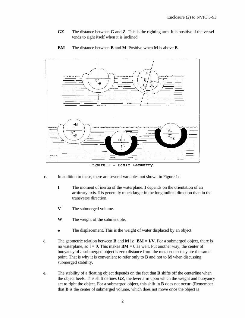
Enclosure (2) to NVIC 5-93
2
GZ The distance between G and Z. This is the righting arm. It is positive if the vesseltends to right itself when it is inclined.
BM The distance between B and M. Positive when M is above B.
c. In addition to these, there are several variables not shown in Figure 1:
I The moment of inertia of the waterplane. I depends on the orientation of anarbitrary axis. I is generally much larger in the longitudinal direction than in thetransverse direction.
V The submerged volume.
W The weight of the submersible.
DD The displacement. This is the weight of water displaced by an object.
d. The geometric relation between B and M is: BM = I/V. For a submerged object, there isno waterplane, so I = 0. This makes BM = 0 as well. Put another way, the center ofbuoyancy of a submerged object is zero distance from the metacenter: they are the samepoint. That is why it is convenient to refer only to B and not to M when discussingsubmerged stability.
e. The stability of a floating object depends on the fact that B shifts off the centerline whenthe object heels. This shift defines GZ, the lever arm upon which the weight and buoyancyact to right the object. For a submerged object, this shift in B does not occur. (Rememberthat B is the center of submerged volume, which does not move once the object is

Enclosure (2) to NVIC 5-93
3
completely submerged.) If all weights associated with the object remain in place, G cannotmove either.
f. Buoyancy forces act vertically upward through B, and weight acts vertically downwardthrough G. In the absence of outside forces, the object will rotate until G is verticallybelow B. See Figure 2. The weight at G is in effect hanging from the buoyancy at B. For asubmerged object in stable equilibrium, G is always vertically below B.
g. Recall that on the surface, I is very different in the transverse and longitudinal directions,so roll stability and trim stability are two very different cases on the surface. Submerged,however, B and G are fixed points that do not depend on I. So submerged stability is notdependent on direction: it is exactly the same in roll and trim. If some outside force acts toheel or trim the body, the restoring moment will be the weight of the object times GZ.Here, GZ = GB sin22, where 22 is the heel or trim angle about any horizontal axis. Thismeans that the restoring moment is the same no matter whether the submersible is inclinedin the longitudinal or transverse direction.
h. In the parlance of naval architecture, "weight" and "displacement" are often interchanged.More correctly, however, "weight" refers to the weight of an object, while "displacement"is the weight of water displaced by the object. It is natural to interchange the two for anobject floating on the surface, because the weight of the object always equals itsdisplacement. This is not so for a submerged object. This distinction is extremelyimportant, because the naval architecture of submersibles involves considerable effort tobalance weight and displacement. If weight exceeds displacement, the submersible willsink. When displacement exceeds weight, the submersible rises. When its weight equalsdisplacement, the submersible is neutrally buoyant, and its depth can be controlled.
3. Hazards.

Enclosure (2) to NVIC 5-93
4
a. While surfaced, the stability of a submersible must be sufficient to safely withstandheeling moments caused by wind, waves, and passenger movement. The passengersubmersibles built to date have been quite stable on the surface. For these, a simplifiedstability test is a conservative, but easy way of confirming surface stability. Theassumptions below ensure that a simplified stability test is appropriate.
b. The significant stability hazard while submerged is the large trimming moment that can begenerated by passenger movement. This can be guarded against by requiring a minimumGB. A submerged inclining test measures the GB. The vessel's stability is also influencedby the weight of the submersible.
c. Also while on the surface, the hatch or hatch coming must be high enough to prevent beingovertopped by 1.2 meter waves, and the embarkation deck must be high enough to bereasonably dry for embarking passengers. Vessel hull and appendage configurations orshapes are important in helping keep the deck dry by deflecting waves. This can beobserved during operational tests.
4. Assumptions.
a. The submersible shown in Figure 2 is a military submarine. This is useful for discussingthe principles of stability but there are some important differences between it and apassenger submersible. All passenger submersibles built so far are configured similar tothe cross sections shown in Figure 3. These guidelines and criteria assume such aconfiguration and are therefore much simpler than earlier guidelines on the subject.Specifically, these guidelines have been developed for submersibles having the followingparameters:
(1) the submersible is less than 100 gross tons;(2) it is less than 19.8 meters LPH (Length of Pressure Hull);(3) it carries 49 or fewer passengers;(4) the submersible will be operating on a route for which the surface test was
performed;(5) the access hatches are on the top centerline, with a diameter not greater than one-half
the main hull diameter;(6) there is no diver lockout; and(7) GB is positive at all times. This may be assumed to be the case if:
(a) the main pressure hull is a circular cylinder;(b) the soft and hard ballast tanks are above the mid-height of the main
pressure hull; and(c) the batteries are installed below the mid-height of the main pressure hull.
b. "Hard" ballast tanks are pressurized water ballast tanks, while "soft" ballast tanks are free-flooding water ballast tanks. It should be noted that the hard ballast tanks can causeconsiderable reduction in GB due to their weight and position above the hull centerline. Insome scenarios, the positioning of these hard ballast tanks above the mid height of themain pressure hull could render the GB negative. There is also a possibility that the vesselcould be unstable on the surface unless the waterplane intersects the soft ballast tanks.
c. A submersible that meets these assumptions will be very stable on the surface and whiletransiting through the surface. This can easily be confirmed with a simplified stability test,
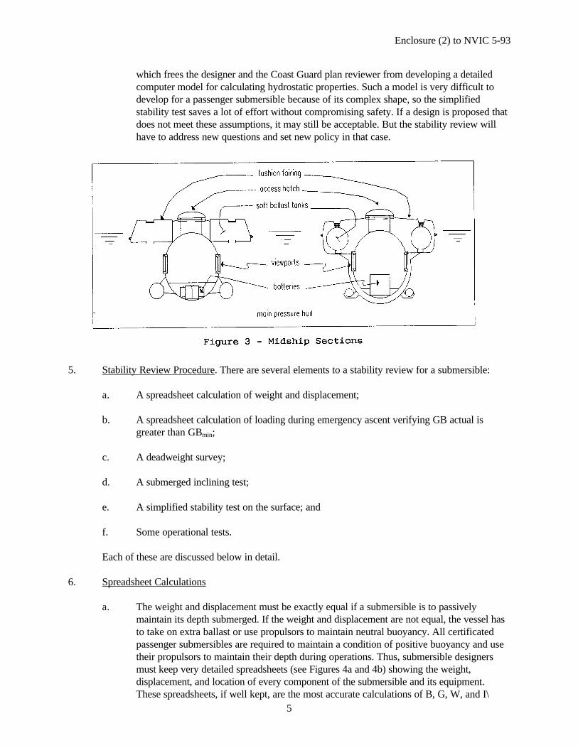
Enclosure (2) to NVIC 5-93
5
which frees the designer and the Coast Guard plan reviewer from developing a detailedcomputer model for calculating hydrostatic properties. Such a model is very difficult todevelop for a passenger submersible because of its complex shape, so the simplifiedstability test saves a lot of effort without compromising safety. If a design is proposed thatdoes not meet these assumptions, it may still be acceptable. But the stability review willhave to address new questions and set new policy in that case.
5. Stability Review Procedure. There are several elements to a stability review for a submersible:
a. A spreadsheet calculation of weight and displacement;
b. A spreadsheet calculation of loading during emergency ascent verifying GB actual isgreater than GBmin;
c. A deadweight survey;
d. A submerged inclining test;
e. A simplified stability test on the surface; and
f. Some operational tests.
Each of these are discussed below in detail.
6. Spreadsheet Calculations
a. The weight and displacement must be exactly equal if a submersible is to passivelymaintain its depth submerged. If the weight and displacement are not equal, the vessel hasto take on extra ballast or use propulsors to maintain neutral buoyancy. All certificatedpassenger submersibles are required to maintain a condition of positive buoyancy and usetheir propulsors to maintain their depth during operations. Thus, submersible designersmust keep very detailed spreadsheets (see Figures 4a and 4b) showing the weight,displacement, and location of every component of the submersible and its equipment.These spreadsheets, if well kept, are the most accurate calculations of B, G, W, and I\
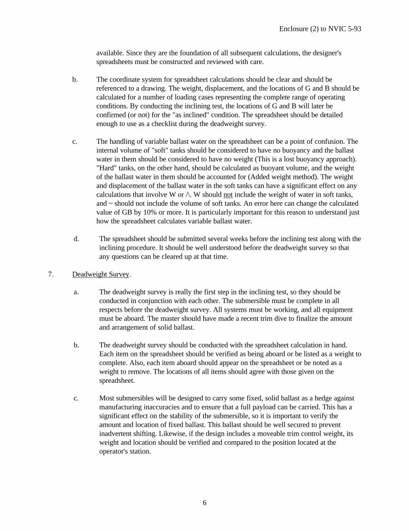
Enclosure (2) to NVIC 5-93
6
available. Since they are the foundation of all subsequent calculations, the designer'sspreadsheets must be constructed and reviewed with care.
b. The coordinate system for spreadsheet calculations should be clear and should bereferenced to a drawing. The weight, displacement, and the locations of G and B should becalculated for a number of loading cases representing the complete range of operatingconditions. By conducting the inclining test, the locations of G and B will later beconfirmed (or not) for the "as inclined" condition. The spreadsheet should be detailedenough to use as a checklist during the deadweight survey.
c. The handling of variable ballast water on the spreadsheet can be a point of confusion. Theinternal volume of "soft" tanks should be considered to have no buoyancy and the ballastwater in them should be considered to have no weight (This is a lost buoyancy approach)."Hard" tanks, on the other hand, should be calculated as buoyant volume, and the weightof the ballast water in them should be accounted for (Added weight method). The weightand displacement of the ballast water in the soft tanks can have a significant effect on anycalculations that involve W or /\. W should not include the weight of water in soft tanks,and ~ should not include the volume of soft tanks. An error here can change the calculatedvalue of GB by 10% or more. It is particularly important for this reason to understand justhow the spreadsheet calculates variable ballast water.
d. The spreadsheet should be submitted several weeks before the inclining test along with theinclining procedure. It should be well understood before the deadweight survey so thatany questions can be cleared up at that time.
7. Deadweight Survey.
a. The deadweight survey is really the first step in the inclining test, so they should beconducted in conjunction with each other. The submersible must be complete in allrespects before the deadweight survey. All systems must be working, and all equipmentmust be aboard. The master should have made a recent trim dive to finalize the amountand arrangement of solid ballast.
b. The deadweight survey should be conducted with the spreadsheet calculation in hand.Each item on the spreadsheet should be verified as being aboard or be listed as a weight tocomplete. Also, each item aboard should appear on the spreadsheet or be noted as aweight to remove. The locations of all items should agree with those given on thespreadsheet.
c. Most submersibles will be designed to carry some fixed, solid ballast as a hedge againstmanufacturing inaccuracies and to ensure that a full payload can be carried. This has asignificant effect on the stability of the submersible, so it is important to verify theamount and location of fixed ballast. This ballast should be well secured to preventinadvertent shifting. Likewise, if the design includes a moveable trim control weight, itsweight and location should be verified and compared to the position located at theoperator's station.
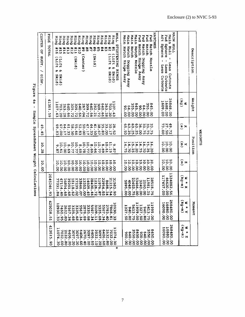
Enclosure (2) to NVIC 5-93
7

Enclosure (2) to NVIC 5-93
8
Enclosure (2) to NVIC 5-93
9
d. It is reasonable that there be provisions for both truly fixed ballast and moveable, variablesolid ballast. For example, if the submersible needs 1000 kilograms of ballast to submergewith minimum payload, it can be expected that something like 800 kilograms will be boltedto the skids. This is truly fixed and is expected to stay there forever. The other 200kilograms might be placed in the battery compartment. It will normally stay there, but maybe relocated, removed, or increased in small amounts to compensate for routine alterationsto machinery and equipment. The operator needs this flexibility, and it can beaccommodated by noting the amount, type, and location of ballast on the stability letter.
e. At least a half-day should be scheduled for the deadweight survey, but it will take longerthan that if the submersible has not been prepared. To facilitate the survey, bilge platesand access panels should be loose so that battery compartments and machinery spaces canbe inspected. The spreadsheet should itemize each piece of equipment; e.g., "10 batteries@ 100 kilograms = 1000 kilograms." This is much easier to account for than "Batteries ---1000 kilograms."
f. The deadweight survey is also a good opportunity to check that all equipment is securelystowed in lockers or racks. Large trim angles are normal in submerged operation.
8. Submerged Inclining Test.
a. American Society of Testing and Materials (ASTM) F 1321-90 has been published as a"Standard Guide for Conducting a Stability Test." It is the basis for this section, and itmust be well understood. This section does not replace ASTM F 1321-90, but addsinformation that was not contemplated when ASTM F 1321-90 was written.
b. In the intact condition, the only significant inclining moment submerged is due topassenger movement. If the distance GB is sufficiently large, the trim angle can be kept tosome safe maximum, even if a percentage of the passengers were to move the entire lengthof the submersible. The following criterion addresses this passenger movement hazard, butpassenger movement should nevertheless be restricted as much as possible.
c. The submersible must be inclined while submerged to determine the actual GB. Under fullload conditions the distance GB 1 determined by the inclining test must be not less thanthe minimum GB determined by the following formula:
GBmin = nwNd I W tan 2
where n = 0.1 (This represents 10% of the passengers all moving at one time.)
w = 72.5 kg per person
N = the total number of passengers aboard
d = the interior length of the main cabin accessible to passengers. This should not includemachinery compartments if they are separated from the main cabin with a bulkhead.
W = the total weight (in units consistent with w) of the fully loaded submersible, not including softballast.

Enclosure (2) to NVIC 5-93
10
22 = 250 (representing the maximum safe trim angle. This assumes that each passenger hasan individual seat that is contoured or upholstered so that a person can remain in it at thisangle.)
d. An object in submerged equilibrium acts exactly as if its center of gravity at G werehanging from its center of buoyancy, B. This is true, regardless of the hydrostaticproperties of the object, and regardless of the direction of inclining. This means thatinclining in the longitudinal direction yields exactly the same result as inclining in thetransverse direction. This is fortunate, because the extra distance available for movinginclining weights makes a longitudinal inclining much easier.
e. Recall from ASTM F 1321-90 that an inclining test measures the relationship:
wd / tan 9
where w is the inclining weight
d is the distance the inclining weight moves
22 is the inclined angle (trim angle, here)
f. Since the weight of the submersible, W, and its center of gravity have been calculatedprecisely on the spreadsheet, the results of the inclining test can be used to calculate theactual GB with the formula:
GBactual = wd / W tan 9
g. Remember that W should be the weight of the submersible, not including the weight of freeflooding water ballast (soft ballast).
h. The following are some special procedures that will help obtain valid results from theinclining test.
(1) In order to maintain its depth during the inclining test, the submersible should besuspended from a small buoy. See Figure 5. The buoy should displace 30-50kilograms. It should be attached near the submersible's longitudinal center ofbuoyancy by a line 9-15 meters long. The submersible should be trimmed to be15-25 kilograms "heavy" so that the buoy will be about 1/2 submerged. Thisshould be observed throughout the test by the surface boat in attendance. Thesuspension buoy should be fairly rigid. Pneumatic fenders tend to compress asthey submerge, and this can make it difficult to achieve neutral buoyancy.
(2) Pendulums should be rigged to swing in the longitudinal direction. They should beas long as possible inside the pressure hull, but even a short pendulum can givegood results. Since the distance GB is constant and does not depend on a smallangle approximation (like GM does), the inclining will be valid at whatever angleis necessary to get readable deflections of the pendulums. Trim angles of 10degrees or even more must be considered normal during diving and ascent, and theresults of the inclining will be just as valid at these angles as at small ones. Take
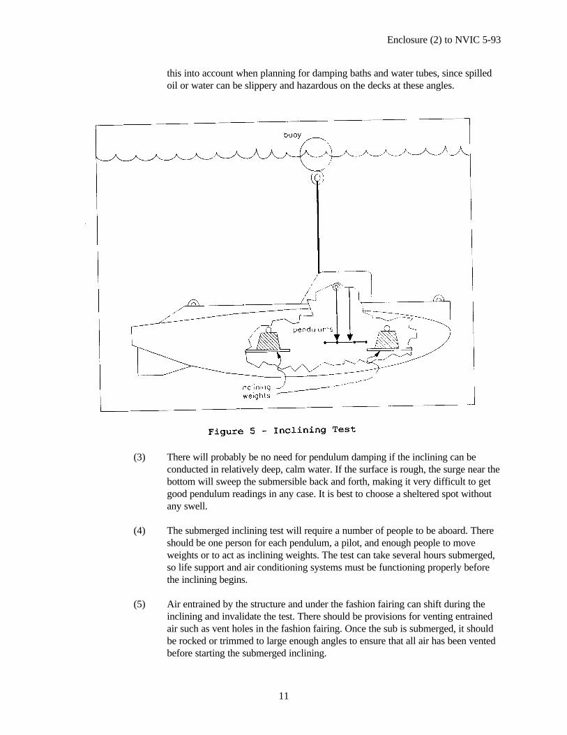
Enclosure (2) to NVIC 5-93
11
this into account when planning for damping baths and water tubes, since spilledoil or water can be slippery and hazardous on the decks at these angles.
(3) There will probably be no need for pendulum damping if the inclining can beconducted in relatively deep, calm water. If the surface is rough, the surge near thebottom will sweep the submersible back and forth, making it very difficult to getgood pendulum readings in any case. It is best to choose a sheltered spot withoutany swell.
(4) The submerged inclining test will require a number of people to be aboard. Thereshould be one person for each pendulum, a pilot, and enough people to moveweights or to act as inclining weights. The test can take several hours submerged,so life support and air conditioning systems must be functioning properly beforethe inclining begins.
(5) Air entrained by the structure and under the fashion fairing can shift during theinclining and invalidate the test. There should be provisions for venting entrainedair such as vent holes in the fashion fairing. Once the sub is submerged, it shouldbe rocked or trimmed to large enough angles to ensure that all air has been ventedbefore starting the submerged inclining.
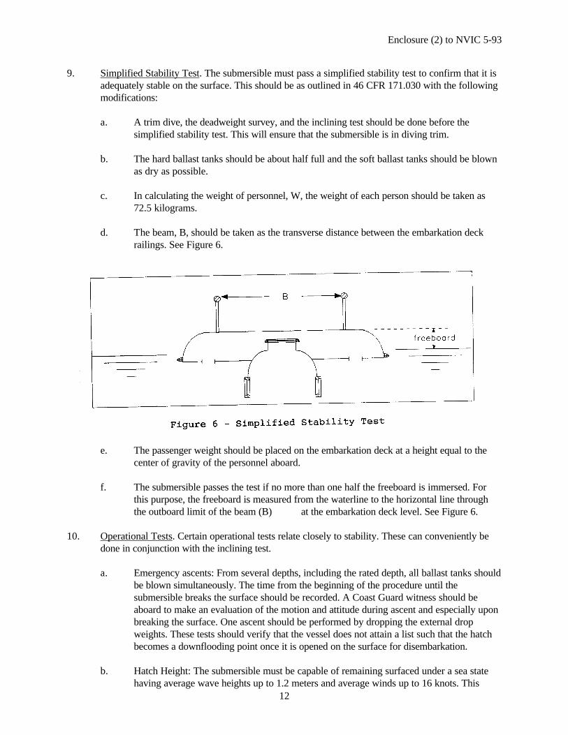
Enclosure (2) to NVIC 5-93
12
9. Simplified Stability Test. The submersible must pass a simplified stability test to confirm that it isadequately stable on the surface. This should be as outlined in 46 CFR 171.030 with the followingmodifications:
a. A trim dive, the deadweight survey, and the inclining test should be done before thesimplified stability test. This will ensure that the submersible is in diving trim.
b. The hard ballast tanks should be about half full and the soft ballast tanks should be blownas dry as possible.
c. In calculating the weight of personnel, W, the weight of each person should be taken as72.5 kilograms.
d. The beam, B, should be taken as the transverse distance between the embarkation deckrailings. See Figure 6.
e. The passenger weight should be placed on the embarkation deck at a height equal to thecenter of gravity of the personnel aboard.
f. The submersible passes the test if no more than one half the freeboard is immersed. Forthis purpose, the freeboard is measured from the waterline to the horizontal line throughthe outboard limit of the beam (B) at the embarkation deck level. See Figure 6.
10. Operational Tests. Certain operational tests relate closely to stability. These can conveniently bedone in conjunction with the inclining test.
a. Emergency ascents: From several depths, including the rated depth, all ballast tanks shouldbe blown simultaneously. The time from the beginning of the procedure until thesubmersible breaks the surface should be recorded. A Coast Guard witness should beaboard to make an evaluation of the motion and attitude during ascent and especially uponbreaking the surface. One ascent should be performed by dropping the external dropweights. These tests should verify that the vessel does not attain a list such that the hatchbecomes a downflooding point once it is opened on the surface for disembarkation.
b. Hatch Height: The submersible must be capable of remaining surfaced under a sea statehaving average wave heights up to 1.2 meters and average winds up to 16 knots. This
Enclosure (2) to NVIC 5-93
13
requirement is similar to American Bureau of Shipping (ABS) procedures which are notnecessarily required or performed except to verify intent of the submersible's operations.ABS has a formula for calculating hatch height, which requires a hydrostatic model andwhich assumes that the critical motion for wave overtopping will be in roll. Observationsof existing submersibles suggest that wave overtopping is usually not a problem, and thatany minor deck wetness comes from heave/pitch motions. As a check, the motion of thesubmersible on the surface should be observed and any tendency for deck wetness shouldbe noted.
c. Damaged ballast tanks: From just below the surface, all possible combinations of ballasttanks should be blown and the equilibrium waterline observed. In each case it should benoted whether the hatches are clear to open. A photographic record of these tests should bekept and included in the vessel file.
d. Trim weight effect: If the pilot controls a moveable trim weight or can control trim withliquid ballast, this should be shifted as far as possible, both fore and aft. Record the trimangles experienced due to these ballast shifts.
e. Effect of passenger movement: With the submersible on an even trim, shift 10% of theintended number of passengers all the way forward and aft. Record the maximum andequilibrium trim angles achieved. The trim angle should not exceed the maximum safeangle for batteries or machinery, and all items of furnishing should remain secure. Themaximum trim angle is not expected to be comfortable, but it should still be possible tomove about the cabin.
11. Stability Letter The end product of the stability review is a stability letter similar to the examplebelow. Note that the stability letter should specifically limit the route to waters not deeper than thecertified test depth and to waters consistent with the route assumed in performing the simplifiedstability test.

Enclosure (2) to NVIC 5-93
14
SAMPLE STABILITY LETTER
NameMaster
Sub]: Submersible _____________ O.N. _______Small Passenger VesselStability Letter
You are responsible for maintaining this vessel in a satisfactory stability condition at all times and forfollowing the instructions and precautions listed below.
A stability test witnessed by the U.S. Coast Guard was conducted on the Submersible ___________ O.N._________,at __________ on ________. On the basis of this test and, a deadweight survey performed onthe subject vesselat ________________ on __________, stability calculations have been performed. Results indicate thatthe stability of ____________ as presently outfitted and equipped is satisfactory for operation bothsurfaced and submerged on protected/partially protected waters as indicated on the Certificate ofInspection, provided that the following restrictions are strictly observed:
OPERATING RESTRICTIONS
1. ROUTE. Partially protected waters not more than meters deep.
2. PASSENGERS. A maximum of _____ passengers may be carried. A maximum of _____ persons(passengers and crew) may be carried. In no case shall the number of persons exceed that allowed by theCertificate of Inspection. All passengers are to remain seated, in the individual seats provided, for the entireduration of each voyage.
3. FREEBOARD AND DRAFT. When surfaced to embark or disembark passengers, all air ballast tanksare to be blown dry so that maximum freeboard is maintained. Trim on the surface should be minimized. Aload line is not authorized.
4. WATERTIGHT OPENINGS. Hatches are to be secured closed and checked before commencing eachdive. They are to remain secured until the surface craft has verified that they are clear of obstructions afterresurfacing. Due to the danger of downflooding, hatches are not to be opened in seas having average waveheights exceeding 1.5 meters.
5. CARGO. No cargo is to be carried.
6. WEIGHT CHANGES. No solid ballast or other such weights shall be added, removed, altered, orrelocated without the authorization and supervision of the cognizant OCMI. All such ballast shall conformto ballast drawing No. _______. The vessel is fitted with _____ kilograms of permanent lead ballast in theskids as well as ______ kilograms of moveable lead ballast in the drop weight tray between the skids and______ kilograms of lead pigs secured in the battery compartment.
7. BILGES. The vessel's bilges shall be kept dry at all times consistent with pollution preventionrequirements.
Enclosure (2) to NVIC 5-93
15
8. FREEING PORTS. Deck freeing ports shall be maintained operable and completely unobstructed at alltimes.
This stability letter shall be posted under suitable transparent material inside the submersible so that allpages are visible. It supersedes the temporary stability letter dated ____________
Sincerely,
(Commanding Officer, Marine Safety Center)
bc: CCGD_(m)
Enclosure (3) to NVIC 5-93
References
American Bureau of Shipping Rules for Building and Classing Underwater Vehicles Systems andHyperbaric Facilities. 1990, American Bureau of Shipping, ABS Americas, 16855 Northchase Drive,Houston, TX 77060
"Safety Standard for Pressure Vessels for Human Occupancy," ANSI/ASME PVHO 1, The AmericanSociety of Mechanical Engineers, United Engineering Center, 345 East 47th Street, New York, NY 10017
Code of Federal Regulations:
Title 46 - Shipping Chapter I - Coast Guard, Department of Transportation:
Subchapter T - Small Passenger Vessels (Under 100 Gross Tons), Parts 175 to 186
Subchapter C - Uninspected Vessels, Parts 24 to 26 Subchapter S - Subdivision andStability, Parts 170 to 174
Subchapter V - Marine Occupational Safety and Health Standards, Part 197
Subchapter H - Passenger Vessels, Parts 70 to 89
Subchapter B - Merchant Marine Officers and Seamen, Parts 10 to 15
Subchapter F - Marine Engineering, Parts 50 to 64 Subchapter J - Electrical Engineering,Parts 110 to 113
Title 33 - Navigation and Navigable Waters, Chapter I - Coast Guard, Department ofTransportation
Subchapter S - Boating Safety, Parts 173 to 183 Subchapter P - Ports and WaterwaysSafety, Parts 160 to 167 Subchapter 0 - Pollution, Parts 151 to 159
Marine Technology Society, Washington, DC:
Safety and Operational Guidelines for Undersea Vehicles
Safety and Operational Guidelines for Undersea Vehicles Book II
International Safety Standard Guidelines for the Operation of Undersea Vehicles
Manned Submersibles by R. Frank Busby, Office of the Oceanographer of the Navy
"Systems Certification Procedures and Criteria Manual for Deep Submergence Systems,NAVMAT P-9290," June 1976, Department of the Navy, Washington, DC 20362
"Code of Practice for Operation of Manned Submersible Craft," Association of Offshore DivingContractors, 28-20 Little Russel Street, London WC1A 2HN

Enclosure (3) to NVIC 5-93
2
"Guidelines for the Selection, Training and Qualification of Deep Submersible Pilots" by the DeepSubmersible Pilots Association
"Procedures for Performing Failure Mode, Effects and Criticality Analysis, MIL-STD-1629A,"November 1980, Department of Defense, Washington, DC 20301
Enclosure (4) to NVIC 5-93
Addresses
Department of the Treasury, U.S. Customs Service, Carriers, Drawbacks, and Bonds Division, CarrierRulings Branch, 1301 Constitution Avenue NW, Washington, D.C. 20229
Commandant (G-MTH), U.S. Coast Guard, 2100 2nd Street SW, Washington, DC 20593-0001
Commandant (G-MVI), U.S. Coast Guard, 2100 2nd Street SW, Washington, DC 20593-0001
Commandant (G-MVP), U.S. Coast Guard, 2100 2nd Street SW, Washington, DC 20593-0001
Marine Safety Center (G-MSC), 400 7th Street SW, Washington, D.C. 20593-0001
Officer in Charge. Marine Inspection
The addresses for each OCMI are as follows. The zone of responsibility for each OCMI is described in 33CFR 3.
ATLANTIC COAST
Commanding Officer, Marine Safety Office, P0 Box 108, Portland, ME 04112-0108
Commanding Officer, Marine Safety Office, 455 Commercial St., Boston, MA 02109-1045
Commanding Officer, Marine Safety Office, John 0'Pastore Federal Bldg., Providence, RI 02903-1790
Commanding Officer, Marine Inspection Office, Battery Park Bldg., New York, NY 10004-1466
Commanding Officer, Marine Safety Office, 1 Washington Ave., Philadelphia, PA 19147-4395
Commanding Officer, Marine Safety Office, Customhouse, 40 5. Gay St., Baltimore, MD 21202-4022
Commanding Officer, Marine Safety Office, Norfolk Federal Bldg., 200 Granby Mall, Norfolk, VA23510-1888
Commanding Officer, Marine Safety Office, Suite 500, 272 North Front St., Wilmington, NC 28401-3907
Commanding Officer, Marine Safety Office, 196 Tradd Street, Charleston, SC 29401-1899
Commanding Officer, Marine Safety Office, P0 Box 8191, Savannah, GA 31402-8191
Commanding Officer, Marine Safety Office, Room 213, 2831 Talleyrand Ave., Jacksonville, FL 32206-3497
Commanding Officer, Marine Safety Office, Claude Pepper Federal Building, 5th Floor, 51 SW 1st. Ave.,Miami FL 33130-1609
Commanding Officer, Marine Safety Office, P0 Box 3666, San Juan, PR 00902-3666

Enclosure (4) to NVIC 5-93
2
GULF OF MEXICO
Commanding Officer, Marine Safety Office, 155 Columbia Drive,
Tampa, FL 33606-3598
Commanding Officer, Marine Safety Office, 150 N. Royal St., PO Box 2924, Mobile, AL 36652-2924
Commanding Officer, Marine Safety Office, Tidewater Bldg., 1440 Canal Street, New Orleans, LA 70112-2711
Commanding Officer, Marine Safety Office, Rm. 232, 800 David Dr., Morgan City, LA 70380-1304
Commanding Officer, Marine Safety Office, Federal Bldg., 2875 75th St. & Hwy. 69, Port Arthur, TX77640-2099
Commanding Officer, Marine Safety Office, Post Office Bldg., Room 313, 601 Rosenberg, Galveston, TX77550-1705
Commanding Officer, Marine Safety Office, PO Box 446, Galena Park, TX 77547-0446
Commanding Officer, Marine Safety Office, P0 Box 1621, Corpus Christi, TX 78403-1621
GREAT LAKES
Commanding Officer, Marine Safety Office, Rm 1111, Federal Bldg., 111 W. Huron St., Buffalo, NY14202-2395
Commanding Officer, Marine Safety Office, 1055 East Ninth St., Cleveland, OH 44114-1092
Commanding Officer, Marine Safety Office, Federal Bldg., Room 501, 234 Summit St., Toledo, OH43604-1590
Commanding Officer, Marine Safety Office, 110 Mt. Elliot Ave., Detroit, MI 48207-4380
Commanding Officer, Marine Inspection Office, Municipal Bldg., St. Ignace, MI 49781-1425
Commanding Officer, Marine Safety Office, Canal Park, Duluth, MN 55802-2352
Commanding Officer, Marine Inspection Office, 57 N. 12th Ave., P0 Box 446, Sturgeon Bay, WI 54235-0446
Commanding Officer, Marine Safety Office, 2420 5. Lincoln Memorial Dr., Milwaukee, WI 53207-1997
Commanding Officer, Marine Safety Office, (MSO Chicago) Suite D, 215 W. 83rd St., Burr Ridge, IL60521-7059
INLAND RIVERS

Enclosure (4) to NVIC 5-93
3
Commanding Officer, Marine Safety Office, Suite 700/Kossman Bldg, Forbes Ave & Stanwix St.,Pittsburgh, PA 15222-1371
Commanding Officer, Marine Safety Office, 1415 6th Ave., Huntington, WV 25701-2420
Commanding Officer, Marine Safety Office, Room 360, 600 Martin Luther King Jr. Place, Louisville, KY40202-2230
Commanding Officer, Marine Safety Office, 225 Tully St., Paducah, KY 42003-7509
Commanding Officer, Marine Safety Office, 1222 Spruce St., St. Louis, MO 63103-2835
Commanding Officer, Marine Safety Office, Suite 1301, 200 Jefferson Ave., Memphis, TN 38103-2300
PACIFIC COAST
Commanding Officer, Marine Safety Office, 2710 N. Harbor Drive, San Diego, CA 92101-1064
Commanding Officer, Marine Safety Office, Los Angeles, Long Beach, 165 N. Pico Ave., Long Beach,CA 90802-1096
Commanding Officer, Marine Safety Office, Bldg. 14, Coast Guard Island, Alameda, CA 94501-5100(MSO San Francisco Bay)
Commanding Officer, Marine Safety Office, 6767 N. Basin Ave., Portland, OR 97217-3929
Commanding Officer, Marine Safety Office, Bldg. 1/Pier 36, 1519 Alaskan Way S., Seattle, WA 98134-1192
Commanding Officer, Marine Safety Office, Suite 2A, 2760 Sherwood Ln., Juneau, AK 99801-8545
Commanding Officer, Marine Safety Office, PO Box 486, Valdez, AK 99686-0486
Commanding Officer, Marine Safety Office, 510 L St., Suite 100, Anchorage, AK 99501-1946
Commanding Officer, Marine Safety Office, 433 Ala Moana Blvd., Rm. 1, Honolulu, HI 96813-4909
Commanding Officer, Marine Safety Office, (MSO Guam) Box 176, FPO San Francisco, CA 96630-0176

Enclosure (5) to NVIC 5-93

Enclosure (5) to NVIC 5-93
2
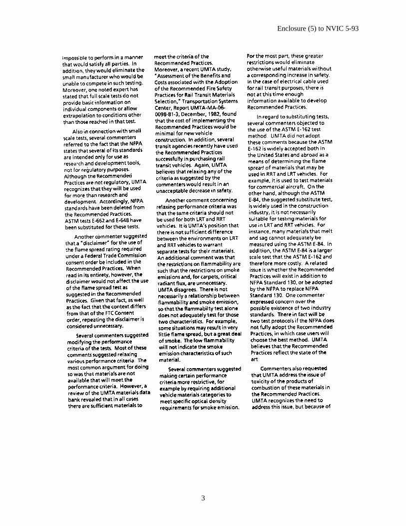
Enclosure (5) to NVIC 5-93
3
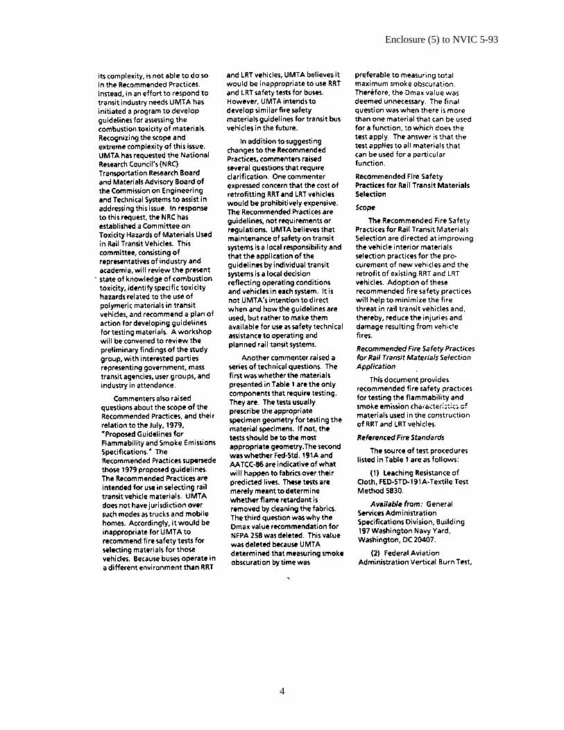
Enclosure (5) to NVIC 5-93
4
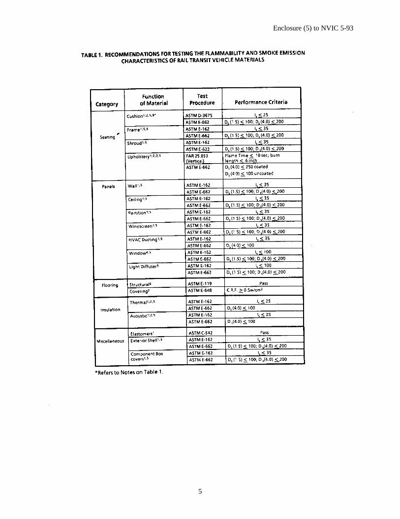
Enclosure (5) to NVIC 5-93
5
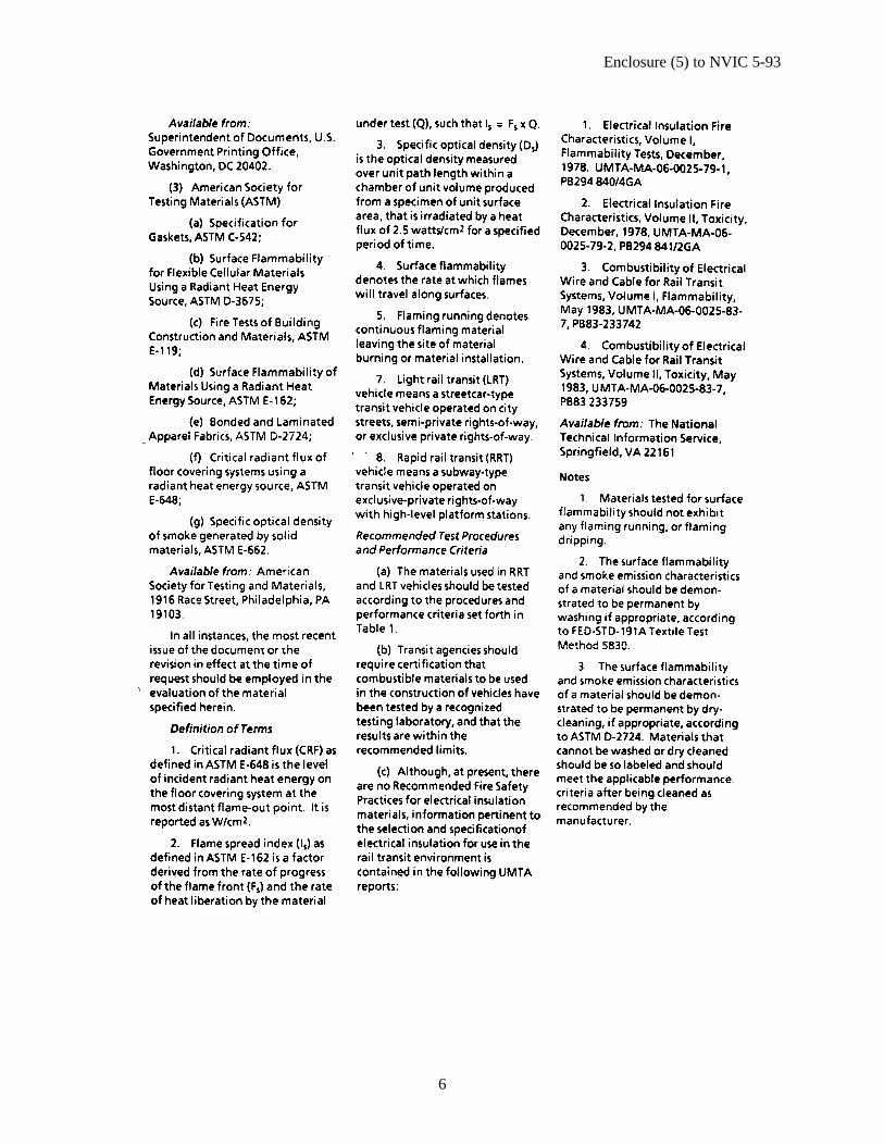
Enclosure (5) to NVIC 5-93
6
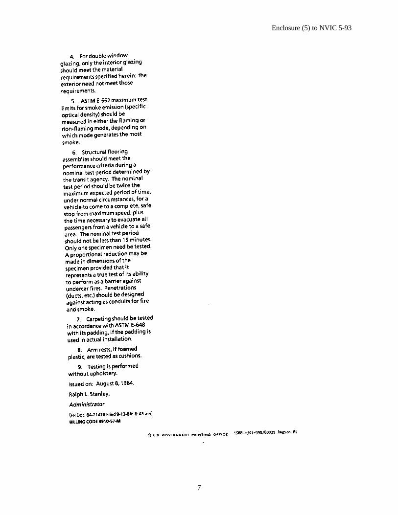
Enclosure (5) to NVIC 5-93
7
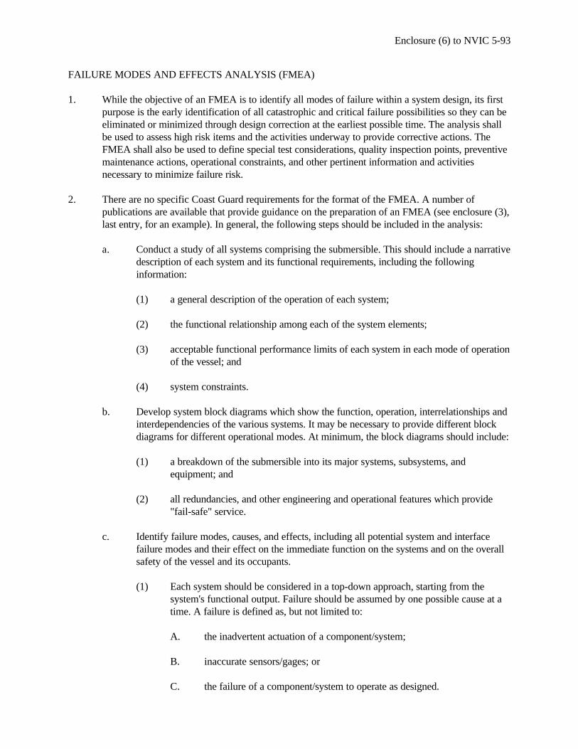
Enclosure (6) to NVIC 5-93
FAILURE MODES AND EFFECTS ANALYSIS (FMEA)
1. While the objective of an FMEA is to identify all modes of failure within a system design, its firstpurpose is the early identification of all catastrophic and critical failure possibilities so they can beeliminated or minimized through design correction at the earliest possible time. The analysis shallbe used to assess high risk items and the activities underway to provide corrective actions. TheFMEA shall also be used to define special test considerations, quality inspection points, preventivemaintenance actions, operational constraints, and other pertinent information and activitiesnecessary to minimize failure risk.
2. There are no specific Coast Guard requirements for the format of the FMEA. A number ofpublications are available that provide guidance on the preparation of an FMEA (see enclosure (3),last entry, for an example). In general, the following steps should be included in the analysis:
a. Conduct a study of all systems comprising the submersible. This should include a narrativedescription of each system and its functional requirements, including the followinginformation:
(1) a general description of the operation of each system;
(2) the functional relationship among each of the system elements;
(3) acceptable functional performance limits of each system in each mode of operationof the vessel; and
(4) system constraints.
b. Develop system block diagrams which show the function, operation, interrelationships andinterdependencies of the various systems. It may be necessary to provide different blockdiagrams for different operational modes. At minimum, the block diagrams should include:
(1) a breakdown of the submersible into its major systems, subsystems, andequipment; and
(2) all redundancies, and other engineering and operational features which provide"fail-safe" service.
c. Identify failure modes, causes, and effects, including all potential system and interfacefailure modes and their effect on the immediate function on the systems and on the overallsafety of the vessel and its occupants.
(1) Each system should be considered in a top-down approach, starting from thesystem's functional output. Failure should be assumed by one possible cause at atime. A failure is defined as, but not limited to:
A. the inadvertent actuation of a component/system;
B. inaccurate sensors/gages; or
C. the failure of a component/system to operate as designed.
Enclosure (5) to NVIC 5-93
2
(2) Since a failure mode can have more than one cause, all potential independentcauses for each failure mode must be identified. If systems or subsystems can failwithout any adverse effect, there is no need to consider them further unless thefailure can go undetected by the crew.
(3) Identification of system redundancy alone is not sufficient to demonstrate that noadverse effect will occur. Redundancy must be shown to be immediately effectiveor brought on line with negligible time lag. In addition, if the sequence is, forinstance: "Failure - alarm - operator action - start of backup - backup in service,"the effects of delay must be considered.
d. Evaluate the consequence of failure modes and their effects. These consequences should beclassified as:
(1) Catastrophic - a failure which may cause death or system loss.
(2) Critical - a failure which may cause severe injury, or major property damage.
(3) Marginal - a failure which may cause minor injury, minor property damage, orminor system damage.
(4) Minor - a failure not serious enough to cause injury, property damage, or systemdamage, but which will result in unscheduled maintenance or repair.
e. If the end effect of a failure is classified as critical or catastrophic, backup equipment orappropriate corrective action is normally required to prevent or minimize such effect.Single failure must not result in a catastrophic event, unless the likelihood is extremelyremote.