Embed Size (px)
Citation preview
Doc. No. 100498DApril 5, 2001
Commands for Host-Commands for Host-Commands for Host-Commands for Host-
Processed and Host-Processed and Host-Processed and Host-Processed and Host-
Controlled ModemsControlled ModemsControlled ModemsControlled ModemsReference ManualReference ManualReference ManualReference Manual
Conexant Proprietary Information

Commands Reference Manual
ii Conexant 100498D
Revision Record
Revision Date Comments
100498D 4/5/2001 Rev. D release. Supersedes 100498C.
100498C(Marked 1118, Rev. 2)
2/5/1999 Rev. C release. Supersedes 100498B andDoc. No. 1163, Rev. 2.
100498B(Marked 1118, Rev. 1)
9/9/1998 Rev. B release. Supersedes 100498A.
100498A(Marked 1118)
5/30/1997 Rev. A release.
© 1997, 1998, 1999, 2001 Conexant Systems, Inc.All Rights Reserved.
Information in this document is provided in connection with Conexant Systems, Inc. (“Conexant”) products. These materials areprovided by Conexant as a service to its customers and may be used for informational purposes only. Conexant assumes noresponsibility for errors or omissions in these materials. Conexant may make changes to specifications and product descriptions atany time, without notice. Conexant makes no commitment to update the information and shall have no responsibility whatsoever forconflicts or incompatibilities arising from future changes to its specifications and product descriptions.
No license, express or implied, by estoppel or otherwise, to any intellectual property rights is granted by this document. Except asprovided in Conexant’s Terms and Conditions of Sale for such products, Conexant assumes no liability whatsoever.
THESE MATERIALS ARE PROVIDED “AS IS” WITHOUT WARRANTY OF ANY KIND, EITHER EXPRESS OR IMPLIED,RELATING TO SALE AND/OR USE OF CONEXANT PRODUCTS INCLUDING LIABILITY OR WARRANTIES RELATING TOFITNESS FOR A PARTICULAR PURPOSE, CONSEQUENTIAL OR INCIDENTAL DAMAGES, MERCHANTABILITY, ORINFRINGEMENT OF ANY PATENT, COPYRIGHT OR OTHER INTELLECTUAL PROPERTY RIGHT. CONEXANT FURTHERDOES NOT WARRANT THE ACCURACY OR COMPLETENESS OF THE INFORMATION, TEXT, GRAPHICS OR OTHER ITEMSCONTAINED WITHIN THESE MATERIALS. CONEXANT SHALL NOT BE LIABLE FOR ANY SPECIAL, INDIRECT, INCIDENTAL,OR CONSEQUENTIAL DAMAGES, INCLUDING WITHOUT LIMITATION, LOST REVENUES OR LOST PROFITS, WHICH MAYRESULT FROM THE USE OF THESE MATERIALS.
Conexant products are not intended for use in medical, lifesaving or life sustaining applications. Conexant customers using or sellingConexant products for use in such applications do so at their own risk and agree to fully indemnify Conexant for any damagesresulting from such improper use or sale.
The following are trademarks of Conexant Systems, Inc.: Conexant™, the Conexant C symbol, “What’s Next in CommunicationsTechnologies”™, SmartDAA™, K56flex™, SmartHCF™, and SmartHSF™. Product names or services listed in this publication arefor identification purposes only, and may be trademarks of third parties. Third-party brands and names are the property of theirrespective owners.
For additional disclaimer information, please consult Conexant’s Legal Information posted at www.conexant.com, which isincorporated by reference.
Reader Response: Conexant strives to produce quality documentation and welcomes your feedback. Please send comments andsuggestions to [email protected]. For technical questions, contact your local Conexant sales office or field applicationsengineer.

Commands Reference Manual
100498D Conexant iii
Contents
1 Introduction ......................................................................................................................................... 1-11.1 Overview .....................................................................................................................................................................1-1
1.1.1 Command Syntax ........................................................................................................................................1-11.1.2 Command Descriptions ...............................................................................................................................1-1
1.2 Reference Documentation ...........................................................................................................................................1-2
2 Syntax and Procedures........................................................................................................................ 2-12.1 Alphabet......................................................................................................................................................................2-12.2 DTE Commands Lines .................................................................................................................................................2-1
2.2.1 Command Line General Format ...................................................................................................................2-12.2.2 Command Line Editing ................................................................................................................................2-22.2.3 Command Line Echo ...................................................................................................................................2-22.2.4 Repeating a Command Line.........................................................................................................................2-22.2.5 Types of DTE Commands ............................................................................................................................2-2
2.3 Basic Syntax Commands.............................................................................................................................................2-32.3.1 Basic Syntax Command Format...................................................................................................................2-32.3.2 S-Parameters ..............................................................................................................................................2-3
2.4 Extended Syntax Commands.......................................................................................................................................2-42.4.1 Command Naming Rules.............................................................................................................................2-42.4.2 Values .........................................................................................................................................................2-4
Numeric Constants ..............................................................................................................................2-4
String Constants ..................................................................................................................................2-5
Compound Values................................................................................................................................2-52.4.3 Action Commands .......................................................................................................................................2-5
Action Execution Command Syntax .....................................................................................................2-5
Action Test Command Syntax ..............................................................................................................2-62.4.4 Parameter Commands.................................................................................................................................2-6
Parameter Types..................................................................................................................................2-6
Parameter Set Command Syntax .........................................................................................................2-6
Parameter Read Command Syntax.......................................................................................................2-7
Parameter Test Command Syntax........................................................................................................2-72.4.5 Additional Syntax Rules...............................................................................................................................2-7
Concatenating Commands after Extended Syntax Commands..............................................................2-7
Concatenating Commands after Basic Format Commands ...................................................................2-72.5 Issuing Commands .....................................................................................................................................................2-82.6 Executing Commands..................................................................................................................................................2-8
2.6.1 Aborting Commands....................................................................................................................................2-82.6.2 Handling of Invalid Numbers and S-Parameter Values.................................................................................2-9
Commands Reference Manual
iv Conexant 100498D
2.7 Modem Responses......................................................................................................................................................2-92.7.1 Responses...................................................................................................................................................2-92.7.2 Extended Syntax Result Codes ..................................................................................................................2-102.7.3 +<name>: <compound_value>Information Text Formats for Test Commands ...........................................2-11
Range of Values.................................................................................................................................2-11
Compound Range of Values...............................................................................................................2-11
3 Data Command Set.............................................................................................................................. 3-13.1 Command Guidelines ..................................................................................................................................................3-1
3.1.1 Escape Code Sequence................................................................................................................................3-13.2 Data Commands..........................................................................................................................................................3-1
3.2.1 Generic Modem Control...............................................................................................................................3-2
Z - Reset to Default Configuration........................................................................................................3-2
+FCLASS - Select Active Service Class.................................................................................................3-2
+VCID - Caller ID (CID) ........................................................................................................................3-3
+VRID - Report Retrieved Caller ID (CID).............................................................................................3-4
\N - Operating Mode ............................................................................................................................3-5
&F - Set to Factory-Defined Configuration............................................................................................3-6
&T - Local Analog Loopback Test ........................................................................................................3-6
I - Request Identification Information ..................................................................................................3-7
+GMI - Request Manufacturer Identification ........................................................................................3-8
+GMM - Request Model Identification..................................................................................................3-9
+GMR - Request Revision Identification...............................................................................................3-9
+GSN - Request Product Serial Number Identification .........................................................................3-9
+GOI - Request Global Object Identification .......................................................................................3-10
+GCAP - Request Complete Capabilities List......................................................................................3-10
+GCI - Country of Installation.............................................................................................................3-113.2.2 DTE-Modem interface commands .............................................................................................................3-12
E - Command Echo ............................................................................................................................3-12
Q - Quiet Results Codes Control ........................................................................................................3-12
V - Result Code Form.........................................................................................................................3-13
W - Connect Message Control ...........................................................................................................3-13
X - Extended Result Codes.................................................................................................................3-14
&C - RLSD Behavior ..........................................................................................................................3-18
&D - DTR Behavior ............................................................................................................................3-19
&K - Flow Control ..............................................................................................................................3-20
&M - Asynchronous/Synchronous Mode Selection............................................................................3-20
&Q - Sync/Async Mode......................................................................................................................3-21
+IPR - Fixed DTE Rate .......................................................................................................................3-22
+IFC - DTE-Modem Local Flow Control ..............................................................................................3-23
+ILRR - DTE-Modem Local Rate Reporting........................................................................................3-243.2.3 Call Control................................................................................................................................................3-25
D - Dial ..............................................................................................................................................3-25
T - Set Tone Dial Default ....................................................................................................................3-27
P - Set Pulse Dial Default ...................................................................................................................3-27
A - Answer.........................................................................................................................................3-27
H - Disconnect (Hang-Up) .................................................................................................................3-28
Commands Reference Manual
100498D Conexant v
O - Return to On-Line Data Mode.......................................................................................................3-28
L - Speaker Volume ...........................................................................................................................3-29
M - Speaker Control...........................................................................................................................3-29
&G - Select Guard Tone .....................................................................................................................3-30
&P - Select Pulse Dial Make/Break Ratio............................................................................................3-30
&V - Display Current Configuration and Stored Profile.......................................................................3-31
&W - Store Current Configuration......................................................................................................3-31
*B - Display Blacklisted Numbers ......................................................................................................3-32
*D - Display Delayed Numbers ..........................................................................................................3-323.2.4 Modulation Control Commands.................................................................................................................3-33
+MS - Modulation Selection...............................................................................................................3-33
+MR - Modulation Reporting Control .................................................................................................3-36
%E - Enable/Disable Line Quality Monitor, Auto-Retrain, and Auto-Rate Renegotiation......................3-373.2.5 Error Control Commands...........................................................................................................................3-38
+ES - Error Control and Synchronous Mode Selection.......................................................................3-38
+EB - Break Handling in Error Control Operation................................................................................3-40
+ESR - Selective Repeat.....................................................................................................................3-40
+EFCS - 32-bit Frame Check Sequence ..............................................................................................3-41
+ER - Error Control Reporting............................................................................................................3-42
+ETBM - Call Termination Buffer Management...................................................................................3-443.2.6 Data Compression Commands ..................................................................................................................3-45
+DS - Data Compression ...................................................................................................................3-45
+DS44 - V.44 Compression Select .....................................................................................................3-46
+DR - Data Compression Reporting...................................................................................................3-47
%C - Enable/Disable Data Compression.............................................................................................3-48
N - Automode Enable.........................................................................................................................3-493.2.7 V.8/V.8bis Commands...............................................................................................................................3-49
+A8E - V.8 and V.8bis Operation Controls..........................................................................................3-49
+A8M - Send V.8 Menu Signals .........................................................................................................3-50
+A8I: - CI Signal Indication ................................................................................................................3-51
+A8C: - Calling Tone Indication..........................................................................................................3-51
+A8A: - Answer Signal Indication.......................................................................................................3-52
+A8J: - V.8 Negotiation Complete ......................................................................................................3-52
+A8M: - V.8 Menu Report ..................................................................................................................3-53
+A8R: - V.8bis Signal and Message Reporting...................................................................................3-533.2.8 Synchronous Access Mode Commands.....................................................................................................3-56
+ESA - Configure Synchronous Access Mode....................................................................................3-56
+ITF - Transmit Flow Control Thresholds ...........................................................................................3-583.2.9 Diagnostic and Test Commands ................................................................................................................3-59
#UD – Last Call Status Report............................................................................................................3-59
%TT - PTT Test Command.................................................................................................................3-663.2.10 V.92 +P and –Q Commands.......................................................................................................................3-69
+PCW - Call Waiting Enable ...............................................................................................................3-69
+PMH - Modem-on-Hold Enable ........................................................................................................3-70
+PMHT – Modem-on-Hold Timer.......................................................................................................3-71
+PMHR - Initiate Modem-on-Hold .....................................................................................................3-72
Commands Reference Manual
vi Conexant 100498D
+PIG - PCM Upstream Ignore ............................................................................................................3-73
+PMHF - V.92 Modem-on-Hold Hook Flash .......................................................................................3-73
+PQC - V.92 Phase 1 and Phase 2 Control .........................................................................................3-74
+PSS - Use Short Sequence...............................................................................................................3-75
-QCPC - Force Full Startup Procedure Next Connection .....................................................................3-76
-QCPS - Enable Quick Connect Profile Save .......................................................................................3-763.3 S-Parameters ............................................................................................................................................................3-77
AT=x - Write to Selected S-Parameter................................................................................................3-77
AT? - Read Selected S-Parameter ......................................................................................................3-77
Sn - Read/Write S-Parameter.............................................................................................................3-783.3.1 Factory Defaults.........................................................................................................................................3-783.3.2 S-Parameter Definitions ............................................................................................................................3-78
S0 - Number of Rings to Automatic Answer ......................................................................................3-78
S1 - Ring Counter ..............................................................................................................................3-78
S2 - Escape Character........................................................................................................................3-79
S3 - Line Termination Character ........................................................................................................3-79
S4 - Response Formatting Character .................................................................................................3-79
S5 - Command Line Editing Character ...............................................................................................3-79
S6 - Wait Time for Dial Tone Before Blind Dialing, or After “W” Dial Modifier ....................................3-80
S7 - Wait Time For Carrier After Dial, For Silence, or For Dial Tone After “W” Dial Modifier ...............3-80
S8 - Pause Time For Dial Delay..........................................................................................................3-80
S10 - Lost Carrier To Hang Up Delay .................................................................................................3-81
S11 - DTMF Tone Duration ................................................................................................................3-81
S12 - Escape Prompt Delay (EPD) .....................................................................................................3-81
S18 - Test Timer ................................................................................................................................3-81
S29 - Flash Dial Modifier Time...........................................................................................................3-81
S30 - Disconnect Inactivity Timer ......................................................................................................3-82
S46 - Data Compression Control .......................................................................................................3-82
S95 - Extended Result Codes Control ................................................................................................3-823.4 Cellular Commands ...................................................................................................................................................3-83
3.4.1 PDC Mode Enable/Disable .........................................................................................................................3-83
+WS - Enable/Disable PDC.................................................................................................................3-833.4.2 PDC High-Speed Data Communication Mode Commands..........................................................................3-84
3.5 Result Codes.............................................................................................................................................................3-85
4 Fax Class 1 and Fax Class 1.0 Commands ........................................................................................... 4-14.1 Fax I/O Processing ......................................................................................................................................................4-1
4.1.1 DTE-to-Modem Transmit Data Stream.........................................................................................................4-14.1.2 Modem-to-DTE Receive Data Stream...........................................................................................................4-14.1.3 Fax Mode Selection .....................................................................................................................................4-14.1.4 Fax Origination ............................................................................................................................................4-34.1.5 Fax Answering .............................................................................................................................................4-34.1.6 Fax Control Transmission ............................................................................................................................4-34.1.7 Fax Control Reception .................................................................................................................................4-34.1.8 Fax Data Transmission ................................................................................................................................4-44.1.9 Fax Data Reception......................................................................................................................................4-5
Commands Reference Manual
100498D Conexant vii
4.2 Commands and Parameters ........................................................................................................................................4-64.2.1 Mode Entry Commands ...............................................................................................................................4-6
+FCLASS=1 - Select Facsimile Class 1 Mode .......................................................................................4-6
+FCLASS=1.0 - Select Facsimile Class 1.0 Mode .................................................................................4-64.2.2 Mode Commands ........................................................................................................................................4-6
+FAE - Auto Answer Enable..................................................................................................................4-6
+FTS - Transmit Silence.......................................................................................................................4-7
+FRS - Receive Silence ........................................................................................................................4-8
+FTM - Transmit Facsimile...................................................................................................................4-9
+FRM - Receive Facsimile ..................................................................................................................4-10
+FTH - Transmit Data with HDLC Framing .........................................................................................4-11
+FRH - Receive Data with HDLC Framing...........................................................................................4-124.2.3 Service Class 1 Parameters .......................................................................................................................4-13
+FAR - Adaptive Reception Control ....................................................................................................4-13
+FCL - Carrier Loss Timeout ..............................................................................................................4-14
+FDD - Double Escape Character Replacement ..................................................................................4-15
+FIT - DTE Inactivity Timeout.............................................................................................................4-16
+FPR - Fixed DTE Rate.......................................................................................................................4-17
+FMI - Request Manufacturer Identification .......................................................................................4-18
+FMM - Request Model Identification ................................................................................................4-18
+FMR - Request Revision Identification .............................................................................................4-18
+FLO - Flow Control...........................................................................................................................4-194.3 Examples...................................................................................................................................................................4-19
5 Voice Commands................................................................................................................................. 5-15.1 Voice Commands Overview.........................................................................................................................................5-1
5.1.1 <DLE> Shielded Event Codes Sent to the DTE..............................................................................................5-25.1.2 <DLE> Shielded Codes Sent to the Modem (DCE) .......................................................................................5-3
5.2 Voice Commands ........................................................................................................................................................5-45.2.1 Configuration Commands............................................................................................................................5-4
+FCLASS=8 - Select Voice Mode .........................................................................................................5-4
+VNH - Automatic Hang-up Control .....................................................................................................5-45.2.2 Voice Commands ........................................................................................................................................5-5
+VIP - Voice Initialize All Parameters ...................................................................................................5-5
+VRX - Start Modem Receive (Record)................................................................................................5-5
+VTR - Start Voice Transmission and Reception (Voice Duplex) ..........................................................5-6
+VTS - Send Voice Tone(s)..................................................................................................................5-7
+VTX - Start Modem Transmit (Playback)............................................................................................5-9
+VGR - Voice Gain Receive (Record Gain) ...........................................................................................5-9
+VGT - Voice Gain Transmit (Playback Volume) ................................................................................5-10
+VIT - Voice Inactivity Timer (DTE/Modem).......................................................................................5-11
+VLS - Analog Source/Destination Selection......................................................................................5-12
+VRA - Ringback Goes Away Timer ...................................................................................................5-13
+VRN - Ringback Never Appeared Timer............................................................................................5-14
+VSD - Silence Detection (Quiet and Silence) ....................................................................................5-15
+VSM - Compression Method Selection ............................................................................................5-16
+VTD - Beep Tone Duration Timer .....................................................................................................5-17

Commands Reference Manual
viii Conexant 100498D
+VDR - Distinctive Ring .....................................................................................................................5-18
+VDT - Control Tone Cadence Reporting............................................................................................5-19
+VBT - Buffer Threshold Setting ........................................................................................................5-20
+VPR - Select DTE/Modem Interface Rate (Turn Off Autobaud) .........................................................5-215.2.3 Speakerphone Commands.........................................................................................................................5-22
+VSP - Speakerphone ON/OFF ...........................................................................................................5-22
+VDX - Speakerphone Duplex Mode ..................................................................................................5-23
+VGM - Microphone Gain ..................................................................................................................5-24
+VGS - Speaker Gain .........................................................................................................................5-25
6 Index.................................................................................................................................................... 6-1
Commands Reference Manual
100498D Conexant ix
Tables
Table 3-1. Result Codes.................................................................................................................................................3-15Table 3-2. +MS Command Supported Rates..................................................................................................................3-33Table 3-3. V.8/V.8bis Example Commands/Responses for Originator and Answerer......................................................3-54Table 3-4. AT#UD Last Call Status Report Format .........................................................................................................3-61Table 3-5. Call Setup Result Codes................................................................................................................................3-62Table 3-6. Multimedia Modes ........................................................................................................................................3-62Table 3-7. DTE-DCE modes ...........................................................................................................................................3-62Table 3-8. V.34 INFO bit report......................................................................................................................................3-62Table 3-9. gstnModulationSchemeActive from 3.7.2/V.58 .............................................................................................3-63Table 3-10. errorControl Active from 3.5.2/V.58 ............................................................................................................3-63Table 3-11. compressionActive from 3.2.2/V.58............................................................................................................3-63Table 3-12. callCleared codes from 3.6.4/V.58-1994 .....................................................................................................3-64Table 3-13. Completed Data Call, with Some Errors and Rate Retrain during the Call ....................................................3-65Table 3-14. S-Parameter Summary ...............................................................................................................................3-77Table 3-15. Result Code Definitions...............................................................................................................................3-86Table 4-1. Fax Class 1 and Fax Class 1.0 Commands.......................................................................................................4-2Table 4-2. Fax Class 1 and Fax Class 1.0 Modulation Modes and Rates...........................................................................4-9Table 4-3. Inactivity Timer Start and Stop Events ..........................................................................................................4-16Table 4-4. Fax Class 1 Calling Sequence (Transmitting a Single Page) ..........................................................................4-20Table 4-5. Fax Class 1 Answering Sequence (Receiving a Single Page) .........................................................................4-21Table 5-1. Voice Commands............................................................................................................................................5-1Table 5-2. Supported <DLE> Shielded Codes Sent to the DTE .........................................................................................5-2Table 5-3. Supported <DLE> Shielded Codes Sent to the Modem (DCE)..........................................................................5-3Table 5-4. +VLS Command Options...............................................................................................................................5-12

Commands Reference Manual
x Conexant 100498D
This page is intentionally blank.
Commands Reference Manual
100498D Conexant 1-1
1 Introduction
1.1 Overview
This manual describes the host command and responses for Conexant host-controlled(HCF) and host-processed (HSF or SoftK56) modem families.
The descriptions in this manual apply to all commands and parameters that may be supportedby different modem models. Refer to Modem Software Release notes for commandsapplicable to specific modem models.
The commands and responses are implemented in host software for specific modem models.Additional configuration and implementation information is available in release notes and/orreadme files that accompany product software release. The .INF File contains exactapplication unique information and default values.
1.1.1 Command Syntax
The fundamental DTE interface command syntax is described in Section 2.
1.1.2 Command Descriptions
These commands are grouped into the following categories:
Syntax and procedures Section 2Data commands Section 3Fax Class 1 and Fax Class 1.0 commands Section 4Voice/Audio commands Section 5

Commands Reference Manual
1-2 Conexant 100498D
1.2 Reference Documentation
Document Title Document No.
RC56HCF-PCI Modem Device Set Designer’s Guide 100759 (formerly 1129)
RC56D-PCI Host Controlled V.90/K56flex Modem Device Family for DesktopApplications Designer’s Guide
100762 (formerly 1174)
SoftK56-PCI Modem Device Set Designer's Guide (Order No. 1160) 100811 (formerly 1160)
SoftK56-PCI Host-Software Processed V.90/K56flex Modem Device Family forDesktop Applications Designer's Guide (Order No. 1201)
100813 (formerly 1201)
RH56LD-PCI Host-Controlled V.90/K56flex Modem Device Family for MobileApplications
100819 (formerly 1164)
RS56L-PCI Host-Processed V.90/K56flex Modem Device Family for MobileApplications
100820 (formerly 1202)
RMH56LD/RMS56LD Host-Controlled/Processed V.90/K56flex Modem DeviceFamily for Mobile Applications (Order No. 1203)
100821 (formerly 1203)
CX11252 HSF Modem, Host-Processed V.92/V.90/K56flex Modem DeviceFamily for PCI-Bus Desktop and Mobile Applications Data Sheet
101309
LAN/Soft V.92 SmartDAA Modem Device Set for PCI Data Sheet 101480
Commands Reference Manual
100498D Conexant 2-1
2 Syntax and Procedures
The command and response syntax and procedures generally conform to referencedrecommendations and standards. Since these recommendations and standards describecharacteristics universal to a large installed base of modems to a maximum degree, there maybe syntax and procedural differences due to extensions and behavioral differences inimplemented commands, parameters, and responses beyond that described in theserecommendations and standards.
The syntax and procedures described in this section are based on V.250 and V.253 withadditional information included for implemented extensions, behavioral differences beyondV.250, and legacy commands.
2.1 Alphabet
The T.50 International Alphabet 5 (IA5) is used in this document. Only the low-order sevenbits of each character are significant to the modem; any eighth or higher-order bit(s), ifpresent, are ignored for the purpose of identifying commands and parameters. Lower-casecharacters are considered identical to their upper-case equivalents when received by themodem from the DTE. Result codes from the modem are in upper case.
2.2 DTE Commands Lines
Words enclosed in <angle brackets> are references to syntactical elements. The brackets arenot used when the words appear in a command line, the brackets are not used. Wordsenclosed in [square brackets] represent optional items which may be omitted from thecommand line at the specified point. The square brackets are not used when the words appearin the command line. Other characters that appear in syntax descriptions must as included asshown.
Any modem responses are mentioned in terms of their alphabetic format; the actual responseissued will depend on the setting of parameters that affect response formats, e.g., Q and Vcommands (see 2.7).
2.2.1 Command Line General Format
A command line is made up of three elements: the prefix, the body, and the terminationcharacter.
The command line prefix consists of the characters "AT" or "at" or, to repeat the execution ofthe previous command line, the characters "A/" or "a/".
The body is made up of individual commands described in this document. Space characters(IA5 2/0) are ignored and may be used freely for formatting purposes, unless they areembedded in numeric or string constants. The termination character may not appear in thebody. The modem can accept at least 40 characters in the body.
The termination character may be selected by a user option (parameter S3), the default beingCR.
Commands Reference Manual
2-2 Conexant 100498D
2.2.2 Command Line Editing
The character defined by parameter S5 (default, BS) is interpreted as a request from the DTEto the modem to delete the previous character. Any control characters (IA5 0/0 through 1/15,inclusive) that remain in the command line after receipt of the termination character areignored by the modem.
The modem checks characters from the DTE first to see if they match the terminationcharacter (S3), then the editing character (S5), before checking for other characters. Thisensures that these characters will be properly recognized even if they are set to values that themodem uses for other purposes. If S3 and S5 are set to the same value, a matching characterwill be treated as matching S3 (S3 is checked before S5).
2.2.3 Command Line Echo
The modem may echo characters received from the DTE during command state and onlinecommand state back to the DTE, depending on the setting of the E command. If enabled,characters received from the DTE are echoed in the same format as received. Invalidcharacters in the command line or incomplete or improperly-formed command line prefixesmay not be echoed.
2.2.4 Repeating a Command Line
If the prefix "A/" or "a/" is received, the modem immediately executes once again the body ofthe preceding command line. No editing is possible, and no termination character isnecessary. A command line may be repeated multiple times in this manner. Responses to therepeated command line are issued using format of the original command line. If "A/" isreceived before any command line has been executed, the preceding command line isassumed to have been empty (that results in an OK result code).
2.2.5 Types of DTE Commands
There are two types of commands: action commands and parameter commands. Commands ofeither type may be included in command lines, in any order.
Action commands may be "executed" (to invoke a particular function of the equipment, whichgenerally involves more than the simple storage of a value for later use), or "tested" (todetermine whether or not the equipment implements the action command, and, ifsubparameters are associated with the action, the ranges of subparameter values that aresupported).
Parameters may be "set" (to store a value or values for later use), "read" (to determine thecurrent value or values stored), or "tested" (to determine whether or not the equipmentimplements the parameter, and the ranges of values supported).

Commands Reference Manual
100498D Conexant 2-3
2.3 Basic Syntax Commands
2.3.1 Basic Syntax Command Format
The format of Basic Syntax commands, except for the D and S commands, is as follows:
<command>[<number>]
where <command> is either a single character, or the "&" character followed by a singlecharacter per V.250. In addition, <command> can be the "%" character followed by a singlecharacter, the "*" character followed by a single character, or the "^" character followed by asingle character.
<number> may be a string of one or more characters from "0" through "9" representing adecimal integer value. Commands that expect a <number> are noted in the description of thecommand. If a command expects <number> and it is missing (<command> is immediatelyfollowed in the command line by another <command> or the termination character), the value"0" is assumed. If a command does not expect a <number> and a number is present, anERROR is generated. All leading "0"s in <number> are ignored by the modem.
Additional commands may follow a command (and associated parameter, if any) on the samecommand line without any character required for separation. The actions of some commandscause the remainder of the command line to be ignored (e.g., A).
See the D command for details on the format of the information that follows it.
2.3.2 S-Parameters
Commands that begin with the letter "S" are known as "S-parameters". The number followingthe "S" indicates the "parameter number" being referenced. If the number is not recognized asa valid parameter number, an ERROR result code is issued.
Immediately following this number, either a "?" or "=" character must appear. "?" is used toread the current value of the indicated S-parameter; "=" is used to set the S-parameter to anew value.
S<parameter_number>?
S<parameter_number>=[<value>]
If the "=" is used, the new value to be stored in the S-parameter is specified in decimalfollowing the "=". If no value is given (i.e., the end of the command line occurs or the nextcommand follows immediately), the S-parameter specified may be set to 0, or an ERRORresult code issued and the stored value left unchanged. The ranges of acceptable values aregiven in the description of each S-parameter.
If the "?" is used, the modem transmits a single line of information text to the DTE. The textportion of this information text consists of exactly three characters, giving the value of the S-parameter in decimal, with leading zeroes included.
Commands Reference Manual
2-4 Conexant 100498D
2.4 Extended Syntax Commands
2.4.1 Command Naming Rules
Both actions and parameters have names, which are used in the related commands. Namesalways begin with the character "+". Following the "+", from one to 16 additional charactersappear in the command name. These characters will be selected from the following set:
A through Z (IA5 4/1 through 5/10)
0 through 9 (IA5 3/0 through 3/9)
! (IA5 2/1)
% (IA5 2/5)
- (IA5 2/13)
. (IA5 2/14)
/ (IA5 2/15)
: (IA5 3/10)
_ (IA5 5/15)
The first character following the "+" must be an alphabetic character in the range of "A"through "Z". This first character generally implies the application in which a command is used(e.g., F for Fax or V for voice).
The modem considers lower-case characters to be the same as their upper-case equivalents.
2.4.2 Values
When subparameters are associated with the execution of an action, or when setting aparameter, the command may include specification of values. This is indicated by theappearance of <value> in the descriptions below.
<value> consists of either a numeric constant or a string constant.
Numeric Constants
Numeric constants are expressed in decimal, hexadecimal, or binary.
Decimal numeric constants consist of a sequence of one or more of the characters "0" through"9", inclusive.
Hexadecimal numeric constants consist of a sequence of one or more of the characters "0"through "9", inclusive, and "A" through "F" inclusive. The characters "A" through "F"represent the equivalent decimal values 10 through 15.
Binary numeric constants consist of a sequence of one or more of the characters "0" and "1".
In all numeric constants, the most significant digit is specified first. Leading "0" charactersare ignored by the modem. No spaces, hyphens, periods, commas, parentheses, or othergenerally-accepted numeric formatting characters are permitted in numeric constants; note inparticular that no "H" suffix is appended to the end of hexadecimal constants.
Commands Reference Manual
100498D Conexant 2-5
String Constants
String constants consist of a sequence of displayable IA5 characters, each in the range from2/0 to 7/15, inclusive, except for the characters ‘"’ (IA5 2/2) and "\" (IA5 5/12). Stringconstants are bounded at the beginning and end by the double-quote character (‘"’, IA5 2/2).
Any character value may be included in the string by representing it as a backslash ("\")character followed by two hexadecimal digits. For example, "\0D" is a string consisting of thesingle character <CR> (IA5 0/13). If the "\" character itself is to be represented in a string, itis encoded as "\5C". The double-quote character, used as the beginning and ending stringdelimiter, is represented within a string constant as "\22".
A "null" string constant, or a string constant of zero length, is represented by two adjacentdelimiters ("").
Compound Values
Actions may have more than one subparameter associated with them, and parameters mayhave more than one value. These are known as "compound values", and their treatment is thesame in both actions and parameters.
A compound value consists of any combination of numeric and string values (as defined inthe description of the action or parameter). The comma character must be included as aseparator, before the second and all subsequent values in the compound value. If a value is notspecified (i.e., defaults assumed), the required comma separator must be specified; however,trailing comma characters may be omitted if all associated values are also omitted.
2.4.3 Action Commands
Action Execution Command Syntax
There are two general types of action commands: those that have associated subparametervalues that affect only that invocation of the command, and those that have no subparameters.
If subparameters are associated with a command, the definition of the action commandindicates, for each subparameter, whether the specification of a value for that subparameter ismandatory or optional. For optional subparameters, the definition indicates the assumed(default) value for the subparameter if no value is specified for that subparameter; theassumed value may be either a previous value (i.e., the value of an omitted subparameterremains the same as the previous invocation of the same command, or is determined by aseparate parameter or other mechanism), or a fixed value (e.g., the value of an omittedsubparameter is assumed to be zero). Generally, the default value for numeric subparametersis 0, and the default value for string subparameters is "" (empty string).
The following syntax is used for actions that have no subparameters:
+<name>
The following syntax is used for actions that have one subparameter:
+<name>[=<value>]
The following syntax is used for actions that have two or more subparameters:
+<name>[=<compound_value>]
For actions that accept subparameters, if all subparameters are defined as being optional, andthe default values for all subparameters are satisfactory, the data terminal equipment (DTE)may use the first syntax above (i.e., omit the "=" from the action execution command as wellas all of the subparameter value string).
Commands Reference Manual
2-6 Conexant 100498D
If all other relevant criteria are met (e.g., the modem is in the proper state), the command isexecuted with any indicated subparameters. If <name> is not recognized, the modem issuesthe ERROR result code and terminates processing of the command line. An ERROR is alsogenerated if a subparameter is specified for an action that does not accept subparameters, iftoo many subparameters are specified, if a mandatory subparameter is not specified, if a valueis specified of the wrong type, or if a value is specified that is not within the supported range.
Action Test Command Syntax
The DTE may test if an action command is implemented in the modem by using the syntax:
+<name>=?
If the modem does not recognize the indicated name, it returns an ERROR result code andterminates processing of the command line. If the modem does recognize the action name, itreturns an OK result code. If the named action accepts one or more subparameters, the modemsends an information text response to the DTE, prior to the OK result code, specifying thevalues supported by the modem for each such subparameter, and possibly additionalinformation. The format of this information text is defined for each action command.
2.4.4 Parameter Commands
Parameter Types
Parameters may be defined as "read-only" or "read-write". "Read-only" parameters are used toprovide status or identifying information to the DTE, but cannot be set by the DTE;attempting to set their value is an error. In some cases (specified in the description of theindividual parameter), the modem may ignore attempts to set the value of such parametersrather than respond with an ERROR result code, if the continued correct operation of theinterface between the modem and DTE will not be affected by such action. Read-onlyparameters may be read and tested.
"Read-write" parameters may be set by the DTE, to store a value or values for later use. Read-write parameters may be set, read, and tested.
Parameters may take either a single value, or multiple (compound) values. Each value may beeither numeric or string; the definition of the parameter will specify the type of value for eachsubparameter. Attempting to store a string value in a numeric parameter, or a numeric value ina string parameter, is an error.
Parameter Set Command Syntax
The definition of the parameter indicates, for each value, whether the specification of thatvalue is mandatory or optional. For optional values, the definition indicates the assumed(default) value if none is specified; the assumed value may be either a previous value (i.e., thevalue of an omitted subparameter retains its previous value), or a fixed value (e.g., the valueof an omitted subparameter is assumed to be zero). Generally, the default value for numericparameters is 0, and the default value for string parameters is "" (empty string).
The following syntax is used for parameters that accept a single value:
+<name>=[<value>]
The following syntax is used for parameters that accept more than one value:
+<name>=[<compound_value>]
For each implemented parameter, if all mandatory values are specified, and all values arevalid according to the definition of the parameter, the specified values are stored. If <name>
Commands Reference Manual
100498D Conexant 2-7
is not recognized, one or more mandatory values are omitted, or one or more values are of thewrong type or outside the permitted range, the modem issues the ERROR result code andterminates processing of the command line. An ERROR is also generated if too many valuesare specified. In case of an error, all previous values of the parameter are unaffected.
Parameter Read Command Syntax
The DTE may determine the current value or values stored in a parameter by using thefollowing syntax:
+<name>?
The modem responds by sending the current values stored for the parameter to the DTE in aninformation text response. The format of this response is described in the definition of theparameter. Generally, the values are sent in the same form in which they would be issued bythe DTE in a parameter setting command; if multiple values are supported, they will generallybe separated by commas, as in a parameter setting command.
Parameter Test Command Syntax
The DTE may test if a parameter is implemented in the modem, and determine the supportedvalues, by using the syntax:
+<name>=?
If the modem does not recognize the indicated name, it returns an ERROR result code andterminates processing of the command line. If the modem does recognize the parameter name,it returns an information text response to the DTE, followed by an OK result code. Theinformation text response indicates the values supported by the modem for each suchsubparameter, and possibly additional information. The format of this information text isdefined for each parameter.
2.4.5 Additional Syntax Rules
Concatenating Commands after Extended Syntax Commands
Additional commands may follow an extended-syntax command on the same command line ifa semicolon (";") is inserted after the preceding extended command as a separator. Thesemicolon is not necessary when the extended syntax command is the last command on thecommand line.
Concatenating Commands after Basic Format Commands
Extended syntax commands may appear on the same command line after a basic syntaxcommand without a separator, in the same manner as concatenation of basic syntaxcommands.
Commands Reference Manual
2-8 Conexant 100498D
2.5 Issuing Commands
All characters in a command line must be issued at the same data rate, and with thesame parity and format.
The modem will ignore any command line that is not properly terminated. The modem mayconsider 30 seconds of mark idle time between any two characters as an improperlyterminated command line. In this case the modem may or may not generate an ERRORmessage. The modem will ignore any characters received from the DTE that are not part of aproperly-formatted command line.
If the maximum number of characters that the modem can accept in the body is exceeded, anERROR result code is generated after the command line is terminated.
The DTE will not begin issuing a subsequent command line until at least one-tenth of asecond has elapsed after receipt of the entire result code issued by the modem in response tothe preceding command line.
2.6 Executing Commands
Upon receipt of the termination character, the modem commences execution of the commandsin the command line in the order received from the DTE. Should execution of a commandresult in an error, or a character be not recognized as a valid command, execution isterminated, the remainder of the command line is ignored, and the ERROR result code isissued. Otherwise, if all commands execute correctly, only the result code associated with thelast command is issued; result codes for preceding commands are suppressed. If nocommands appear in the command line, the OK result code is issued.
2.6.1 Aborting Commands
Some action commands that require time to execute may be aborted while in progress; theseare explicitly noted in the description of the command. Aborting of commands isaccomplished by the transmission from the DTE to the modem of any character. A singlecharacter is sufficient to abort the command in progress; however, characters transmittedduring the first 125 milliseconds after transmission of the termination character are ignored(to allow for the DTE to append additional control characters such as line feed after thecommand line termination character). To ensure that the aborting character is recognizedby the modem, it should be sent at the same rate as the preceding command line; themodem may ignore characters sent at other rates. When such an aborting event isrecognized by the modem, the modem terminates the command in progress and returns anappropriate result code to the DTE, as specified for the particular command.
Commands Reference Manual
100498D Conexant 2-9
2.6.2 Handling of Invalid Numbers and S-Parameter Values
The modem reacts to undefined numbers and S-parameter values in one of three ways:
1. Issue the ERROR result code, and leave the previous value of the parameter unchanged;
2. Issue the OK result code, and leave the previous value of the parameter unchanged; or,
3. Issue the OK result code, and set the parameter value to the valid value nearest to thatspecified in the command line.
The description of each command specifies which of these three techniques is used to handleinvalid parameter values for that command or parameter.
2.7 Modem Responses
While in command state and online command state, the modem will issue responses using thesame rate, word length, and parity as the most recently received DTE command line. In theevent that no DTE command has yet been received, rate, word length, and parity used willdepend on the capabilities of the modem.
When the modem transitions from the command state or online command state to the onlinedata state, the result code CONNECT should be issued at the bit rate and parity used duringthe command state. When the modem transitions from the online data state to the commandstate or online command state, the result codes should be issued at the bit rate used during theonline data state. Thereafter, any unsolicited result codes should use the bit rate and parity ofthe last command line issued by the DTE to the modem.
The characters of a response will be contiguous, with no more than 100 milliseconds of markidle issued between characters in addition to stop elements.
2.7.1 Responses
There are two types of responses that may be issued by the modem: information text andresult codes.
Information Text. Information text responses consist of three parts: a header, informationtext, and a trailer:
1. The characters transmitted for the header are determined by the V command.
2. The trailer consists of two characters, being the character having the ordinal value ofparameter S3 followed by the character having the ordinal value of parameter S4.
3. Information text usually consists of a single line; information text returned in response tosome commands may contain multiple lines, and the text may therefore include CR, LF,and other formatting characters to improve readability.
Result Code Parts. Result codes consist of three parts: a header, the result text, and a trailer.
1. The characters transmitted for the header and trailer are determined by the V commandsetting.
2. The result text may be transmitted as a number or as a string, also depending on a the Vcommand setting.

Commands Reference Manual
2-10 Conexant 100498D
Result Code Types. There are three types of result codes: final, intermediate, and unsolicited.Result codes are described in Section 3.5.
1. A final result code indicates the completion of a full modem action and an ability toaccept new commands from the DTE.
2. An intermediate result code is a report of the progress of an modem action. TheCONNECT result code is an intermediate result code. In the case of a dialing oranswering command, the modem switches from command state to online data state, andissues a CONNECT result code. This is an intermediate result code for the modembecause it cannot accept commands from the DTE while in online data state. When themodem switches back to the command state it then issues a final result code (such as OKor NO CARRIER).
3. Unsolicited result codes (such as RING) indicate the occurrence of an event not directlyassociated with the issuance of a command from the DTE.
2.7.2 Extended Syntax Result Codes
Extended syntax result codes may be issued in response to either basic or extendedcommands, or both. The appropriate responses are specified in the definitions of thecommands, the responses, or both.
The general format of extended syntax result codes is the same as result codes defined in TIA-602 with regard to headers and trailers. The characters specified in S-parameters S3 and S4are used in headers and trailers of extended syntax result codes as they are in basic formatresult codes. The setting of the V command affects the headers and trailers associated withextended syntax result codes in the same manner as basic format result codes; however, unlikebasic format result codes, extended syntax result codes have no numeric equivalent, and arealways issued in alphabetic form.
Extended syntax result codes are subject to suppression by the Q1 command, as with basicformat result codes. The issuance of extended syntax result codes are not be affected by thesetting of the X command.
Extended syntax result codes may be either final, intermediate, or unsolicited; the type beingindicated in the definition of the result code.
Extended syntax result codes are prefixed by the "+" character to avoid duplication of basicformat result codes specified in TIA-602. Following the "+" character, the name of the resultcode appears; result code names follow the same rules as command names.
Extended syntax result codes may include the reporting of values. The definition of the resultcode specifies whether or not values are appended to the result code, and, if so, how many,their types, and their assumed default values if omitted.
Data/voice Modes. When no values are to be reported, the result code appears in the simplestform:
+<name>
If a single value is to be reported, the form of the result code is:
+<name>: <value>
A single space character separates the colon character from the <value>; no space appearsbetween the result code name and the colon. If multiple values are to be reported with theresult code, the form is:
+<name>: <compound_value>

Commands Reference Manual
100498D Conexant 2-11
Fax Modes. If a single value is to be reported, the form of the result code is:
<value> or (<value>)
2.7.3 +<name>: <compound_value>Information Text Formats for Test Commands
In general, the format of information text returned by extended syntax commands is describedin the definition of the command.
The modem may insert intermediate <CR> characters in very long information text responsesin order to avoid overrunning DTE receive buffers. If intermediate <CR> characters areincluded, the modem does not include the character sequences "0 <CR>"or "OK<CR>", sothat DTE can avoid false detection of the end of these information text responses.
Range of Values
When the action accepts a single numeric subparameter, or the parameter accepts only onenumeric value, the set of supported values may be presented in the information text as anordered list of values. The list is preceded by a left parenthesis (() , and is followed by a rightparenthesis ()). If only a single value is supported, it appears between the parentheses. If morethan one value is supported, then the values may be listed individually, separated by commacharacters, or, when a continuous range of values is supported, by the first value in the range,followed by a hyphen character (-), followed by the last value in the range. The specificationof single values and ranges of values may be intermixed within a single information text. Inall cases, the supported values are indicated in ascending order.
For example, the following are some examples of value range indications:
(0) Only the value 0 is supported.
(1,2,3) The values 1, 2, and 3 are supported.
(1-3) The values 1 through 3 are supported.
(0,4,5,6,9,11,12) The several listed values are supported.
(0,4-6,9,11-12) An alternative expression of the above list.
Compound Range of Values
When the action accepts more than one subparameter, or the parameter accepts more than onevalue, the set of supported values is presented as a list of the parenthetically-enclosed valuerange strings described above, separated by commas. For example, the information text inresponse to testing an action that accepts three subparameters, and supports various ranges foreach of them, could appear as follows:
(0),(1-3),(0,4-6,9,11-12)
This indicates that the first subparameter accepts only the value 0, the second accepts anyvalue from 1 through 3 inclusive, and the third subparameter accepts any of the values 0, 4, 5,6, 9, 11, or 12.

Commands Reference Manual
2-12 Conexant 100498D
This page is intentionally blank.

Commands Reference Manual
100498D Conexant 3-1
3 Data Command Set
3.1 Command Guidelines
The commands used to control and report modem operation in data modem mode are definedin this section.
The Data Modem Mode commands and responses described in this section are applicablewhen command +FCLASS=0. (See +FCLASS in Section 3.2.1 for the definition of theFCLASS command.)
The default values are typical of a fully configured modem supporting all data rates andoptions. The actual default value is dependent upon modem software as defined by the .INFFile.
Commands are accepted by the modem once the previous command has been fully executed,which is normally indicated by the return of an appropriate result code. Execution ofcommands D and A, either as a result of a direct command or a re-execute command, will beaborted if another character is entered before completion of the handshake.
3.1.1 Escape Code Sequence
When the modem has established a connection and has entered on-line data mode, it ispossible to break into the data transmission in order to issue further commands to the modemin an on-line command mode. This is achieved by the DTE sending to the modem a sequenceof three ASCII characters specified by register S2. The default character is '+'. The maximumtime allowed between receipt of the last character of the three escape character sequence fromthe DTE and sending of the OK result code to the DTE is controlled by the S12 register.
3.2 Data Commands
The modem will respond to the commands detailed below. Parameters applicable to eachcommand are listed with the command description. The defaults shown correspond to defaultvalues provided in the .INF File.
Commands Reference Manual
3-2 Conexant 100498D
3.2.1 Generic Modem Control
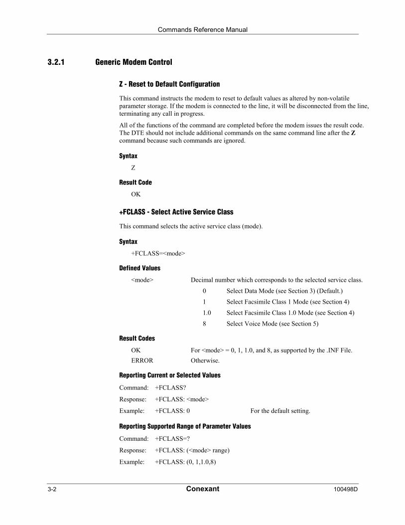
Z - Reset to Default Configuration
This command instructs the modem to reset to default values as altered by non-volatileparameter storage. If the modem is connected to the line, it will be disconnected from the line,terminating any call in progress.
All of the functions of the command are completed before the modem issues the result code.The DTE should not include additional commands on the same command line after the Zcommand because such commands are ignored.
Syntax
Z
Result Code
OK
+FCLASS - Select Active Service Class
This command selects the active service class (mode).
Syntax
+FCLASS=<mode>
Defined Values
<mode> Decimal number which corresponds to the selected service class.
0 Select Data Mode (see Section 3) (Default.)
1 Select Facsimile Class 1 Mode (see Section 4)
1.0 Select Facsimile Class 1.0 Mode (see Section 4)
8 Select Voice Mode (see Section 5)
Result Codes
OK For <mode> = 0, 1, 1.0, and 8, as supported by the .INF File.
ERROR Otherwise.
Reporting Current or Selected Values
Command: +FCLASS?
Response: +FCLASS: <mode>
Example: +FCLASS: 0 For the default setting.
Reporting Supported Range of Parameter Values
Command: +FCLASS=?
Response: +FCLASS: (<mode> range)
Example: +FCLASS: (0, 1,1.0,8)
Commands Reference Manual
100498D Conexant 3-3
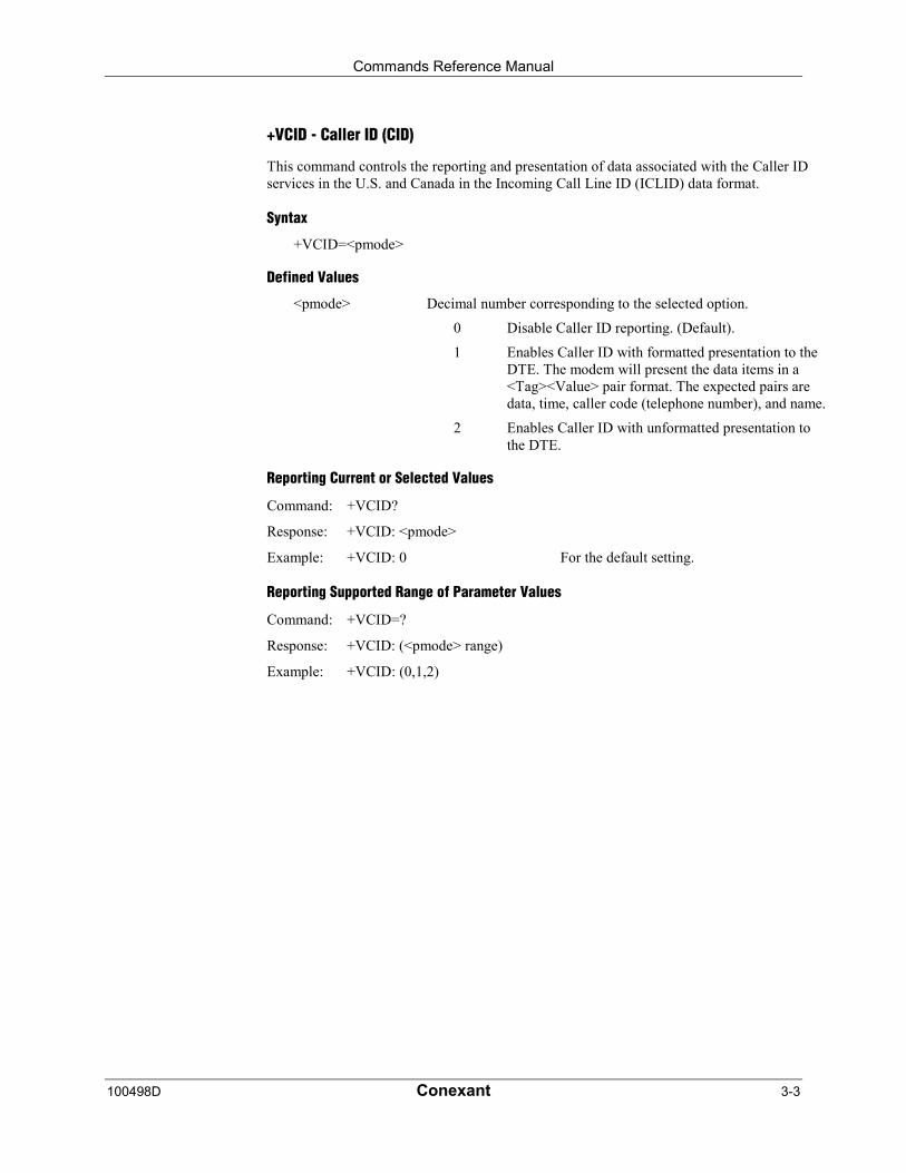
+VCID - Caller ID (CID)
This command controls the reporting and presentation of data associated with the Caller IDservices in the U.S. and Canada in the Incoming Call Line ID (ICLID) data format.
Syntax
+VCID=<pmode>
Defined Values
<pmode> Decimal number corresponding to the selected option.
0 Disable Caller ID reporting. (Default).
1 Enables Caller ID with formatted presentation to theDTE. The modem will present the data items in a<Tag><Value> pair format. The expected pairs aredata, time, caller code (telephone number), and name.
2 Enables Caller ID with unformatted presentation tothe DTE.
Reporting Current or Selected Values
Command: +VCID?
Response: +VCID: <pmode>
Example: +VCID: 0 For the default setting.
Reporting Supported Range of Parameter Values
Command: +VCID=?
Response: +VCID: (<pmode> range)
Example: +VCID: (0,1,2)
Commands Reference Manual
3-4 Conexant 100498D
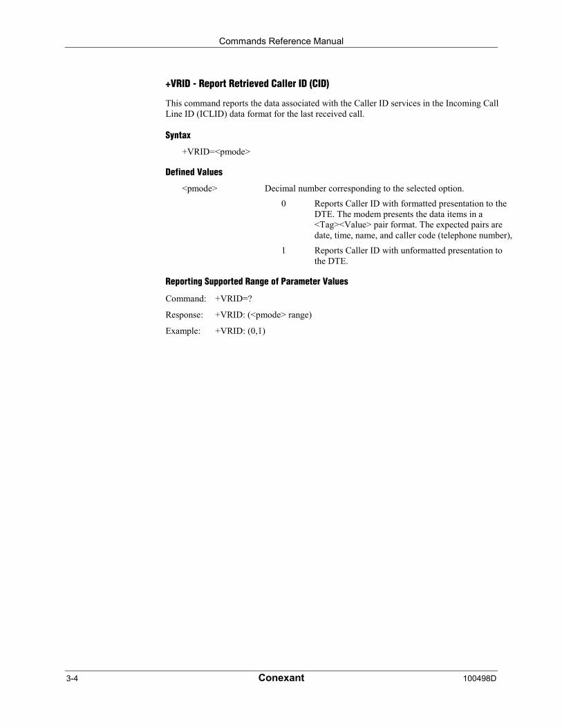
+VRID - Report Retrieved Caller ID (CID)
This command reports the data associated with the Caller ID services in the Incoming CallLine ID (ICLID) data format for the last received call.
Syntax
+VRID=<pmode>
Defined Values
<pmode> Decimal number corresponding to the selected option.
0 Reports Caller ID with formatted presentation to theDTE. The modem presents the data items in a<Tag><Value> pair format. The expected pairs aredate, time, name, and caller code (telephone number),
1 Reports Caller ID with unformatted presentation tothe DTE.
Reporting Supported Range of Parameter Values
Command: +VRID=?
Response: +VRID: (<pmode> range)
Example: +VRID: (0,1)
Commands Reference Manual
100498D Conexant 3-5
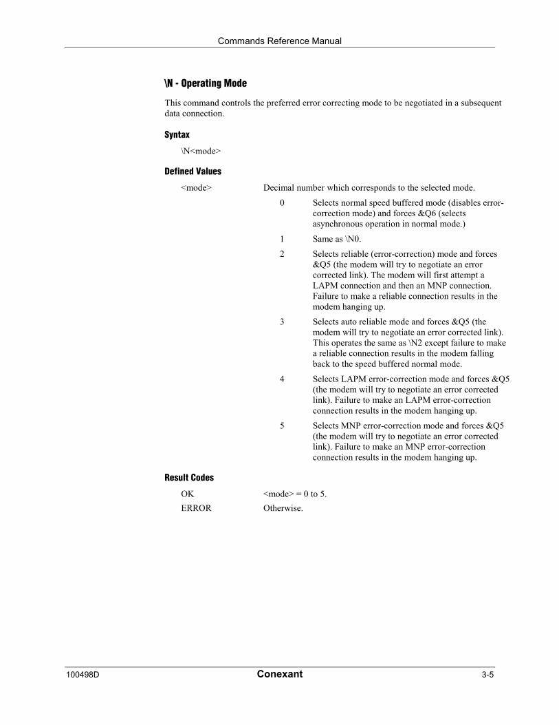
\N - Operating Mode
This command controls the preferred error correcting mode to be negotiated in a subsequentdata connection.
Syntax
\N<mode>
Defined Values
<mode> Decimal number which corresponds to the selected mode.
0 Selects normal speed buffered mode (disables error-correction mode) and forces &Q6 (selectsasynchronous operation in normal mode.)
1 Same as \N0.
2 Selects reliable (error-correction) mode and forces&Q5 (the modem will try to negotiate an errorcorrected link). The modem will first attempt aLAPM connection and then an MNP connection.Failure to make a reliable connection results in themodem hanging up.
3 Selects auto reliable mode and forces &Q5 (themodem will try to negotiate an error corrected link).This operates the same as \N2 except failure to makea reliable connection results in the modem fallingback to the speed buffered normal mode.
4 Selects LAPM error-correction mode and forces &Q5(the modem will try to negotiate an error correctedlink). Failure to make an LAPM error-correctionconnection results in the modem hanging up.
5 Selects MNP error-correction mode and forces &Q5(the modem will try to negotiate an error correctedlink). Failure to make an MNP error-correctionconnection results in the modem hanging up.
Result Codes
OK <mode> = 0 to 5.
ERROR Otherwise.

Commands Reference Manual
3-6 Conexant 100498D
&F - Set to Factory-Defined Configuration
This command instructs the modem to set all parameters to factory default values defined inthe product Configuration Table
The modem loads the factory default configuration (profile). The factory defaults areidentified for each command and in the S-Parameter descriptions. A configuration (profile)consists of a subset of S-Parameters.
Syntax
&F
Result Code
OK
&T - Local Analog Loopback Test
The modem will perform the local analog loopback test if &T1 is selected. The test can be runonly when in an asynchronous operation in non-error-correction mode (normal). To terminatethe test in progress, the escape sequence must be entered first (see Section 3.1.1). If S18 isnon-zero, the test will terminate automatically after the time specified by S18 and the OKresult code will be reported.
Syntax
&T[<value>]
Defined Values
<value> Decimal number corresponding to the selected value.
0 Terminates test in progress.
1 Initiates local analog loopback, V.54 Loop 3. If aconnection exists when this command is issued, themodem hangs up. The CONNECT XXXX message isdisplayed upon the start of the test.
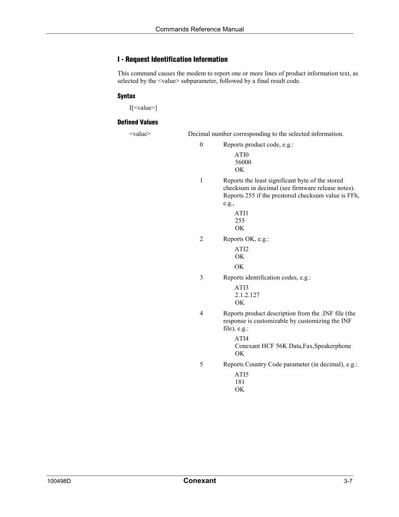
Commands Reference Manual
100498D Conexant 3-7
I - Request Identification Information
This command causes the modem to report one or more lines of product information text, asselected by the <value> subparameter, followed by a final result code.
Syntax
I[<value>]
Defined Values
<value> Decimal number corresponding to the selected information.
0 Reports product code, e.g.:
ATI056000OK
1 Reports the least significant byte of the storedchecksum in decimal (see firmware release notes).Reports 255 if the prestored checksum value is FFh,e.g.,
ATI1255OK
2 Reports OK, e.g.:
ATI2OK
OK
3 Reports identification codes, e.g.:
ATI32.1.2.127OK
4 Reports product description from the .INF file (theresponse is customizable by customizing the INFfile), e.g.:
ATI4Conexant HCF 56K Data,Fax,SpeakerphoneOK
5 Reports Country Code parameter (in decimal), e.g.:
ATI5181OK
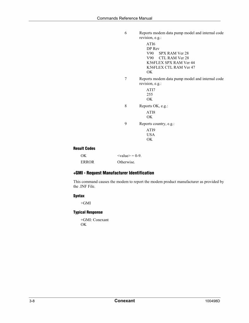
Commands Reference Manual
3-8 Conexant 100498D
6 Reports modem data pump model and internal coderevision, e.g.:
ATI6DP RevV90 SPX RAM Ver 28V90 CTL RAM Ver 28K56FLEX SPX RAM Ver 44K56FLEX CTL RAM Ver 47OK
7 Reports modem data pump model and internal coderevision, e.g.:
ATI7255OK
8 Reports OK, e.g.:
ATI8OK
9 Reports country, e.g.:
ATI9USAOK
Result Codes
OK <value> = 0-9.
ERROR Otherwise.
+GMI - Request Manufacturer Identification
This command causes the modem to report the modem product manufacturer as provided bythe .INF File.
Syntax
+GMI
Typical Response
+GMI: ConexantOK
Commands Reference Manual
100498D Conexant 3-9
+GMM - Request Model Identification
This command causes the modem to report the modem product model as provided by the .INFFile.
Syntax
+GMM
Typical Response
+GMM: HCF 56K Data, Fax, Speakerphone, PCI ModemOK
+GMR - Request Revision Identification
This command causes the modem to report the modem version, revision level, or date asprovided by the .INF File.
Syntax
+GMR
Typical Response
+GMR: 1.0OK
+GSN - Request Product Serial Number Identification
This command causes the modem to report the modem product model serial number asprovided by the .INF File.
Syntax
+GSN
Typical Response
+GSN:OK
Commands Reference Manual
3-10 Conexant 100498D
+GOI - Request Global Object Identification
This command causes the modem to transmit one or more lines of information text identifyingthe device, based on the ISO system for registering unique object identifiers. Typically, thetext consists of a single line containing numeric strings delimited by period characters. Thegeneral format of object identifiers is defined in Section 28 of ITU-T RecommendationX.208; the encoding rules are defined in ITU-T Recommendation X.209. The response isprovided by the .INF file.
Syntax
+GOI
Typical Response
+GOI:OK
+GCAP - Request Complete Capabilities List
This extended-format command causes the modem to transmit one or more lines ofinformation text listing additional capabilities command +<name>s , which is intended topermit the user to identify the overall capabilities of the modem. In particular, if the modemimplements a particular modem control standard that uses Extended Syntax Commands, and ifthat modem control standard includes command(s) that indicate general capabilities, the+<names>(s) of those commands will be reported to the modem in response to a +GCAPcommand.
Syntax
+GCAP
Example Responses
+GCAP: +FCLASS, +MS, +ES, +DS, for a data modem that supports all capabilitieslisted
Where:
+FCLASS T.class1, +F (Class 1 Facsimile modem Control)
+MS +M commands (Modulation Control: +MS and +MR commands)
+ES +E commands (Error Control: +ES, +EB, +ER, +EFCS, +ETBM)
+DS +D commands (Data Compression: +DS and +DR)
Commands Reference Manual
100498D Conexant 3-11
+GCI - Country of Installation
This extended syntax command indicates and selects the country of installation for themodem. This parameter selects the settings for any operational parameters that need to beadjusted for national regulations or telephone networks.
Syntax
+GCI=<country_code>
Defined Values
<country_code> 8-bit country code from Annex A of T.35. The value is thehexadecimal equivalent of the T.35 code, with bit 8 treated as themost significant bit and bit 1 treated as the least significant bit.
Default
If the modem is specified for use in only one country, that country code is the default.Otherwise, the default is the expected country of sale or first installation. The modem may usehardware means to select the country of installation, in which case the modem uses that todetermine the default value.
Reporting Current or Selected Values
Command: +GCI?
Response: +GCI: <current country_code>
Example: +GCI: 3D Indicates that the modem is set for France.
Reporting Supported Range of Parameter Values
Command: +GCI=?
Response: +GCI: (<country_code>[,<country_code>[,<country_code].......]]
Example: +GCI: (20,73,B5) The modem can be set for Canada, Mexicoor the United States.

Commands Reference Manual
3-12 Conexant 100498D
3.2.2 DTE-Modem interface commands
The parameters defined in this section control the operation of the interface between the DTEand modem.
E - Command Echo
The modem enables or disables the echo of characters to the DTE according to the parametersupplied.
Syntax
E[value>]
Defined Values
<value> Decimal number corresponding to the selected option.
0 Disables command echo.
1 Enables command echo. (Default.)
Result Codes
OK <value> = 0 or 1.
ERROR Otherwise.
Q - Quiet Results Codes Control
The command enables or disables the sending of result codes to the DTE according to theparameter supplied. The parameter value, if valid, is written to S14 bit 2.
Syntax
O[value>]
Defined Values
<value> Decimal number corresponding to the selected option.
0 Enables result codes to the DTE. (Default.)
1 Disables result codes to the DTE.
Result Codes
OK <value> = 0 or 1.
ERROR Otherwise.
Commands Reference Manual
100498D Conexant 3-13
V - Result Code Form
This command selects the sending of short-form or long-form result codes to the DTE.
Syntax
V[value>]
Defined Values
<value> Decimal number corresponding to the selected option.
0 Enables short-form (terse) result codes. Line feed isnot issued before a short-form result code.
1 Enables long-form (verbose) result codes. (Default.)
Result Codes
OK <value> = 0 or 1.
ERROR Otherwise.
W - Connect Message Control
This command, in conjunction with S95 bits 0, 2, 3, and 5 (bits 2, 3, and 5 can be writtendirectly by the host or by the +MR, +ER, and +DR commands, respectively), control theformat of CONNECT messages (see Section 3.5 and Table 3-15). The actual result codemessages reported reflect the W command setting and the S95 bit settings. (Also see +MR,+ER, and +DR commands.)
Syntax
W[value>]
Defined Values
<value> Decimal number corresponding to the selected option.
0 Upon connection, the modem reports only the DTEspeed (e.g., CONNECT 19200). Subsequentresponses are disabled. (Default.)
1 Upon connection, the modem reports the line speed,the error correction protocol, and the DTE speed,respectively. Subsequent responses are disabled.
2 Upon connection, the modem reports the DCE speed(e.g., CONNECT 14400). Subsequent responses aredisabled.
3 Upon connection, the modem reports DCE speed andthe error correction protocol.
Result Codes
OK <value> = 0-3.
ERROR Otherwise.

Commands Reference Manual
3-14 Conexant 100498D
X - Extended Result Codes
This command selects the subset of the result code messages used by the modem to informthe DTE of the results of commands.
Blind dialing is enabled or disabled by country parameters. If the user wishes to enforce dialtone detection, a "W" can be placed in the dial string (see D command). The informationbelow is based upon the default implementation of the X results table. Table 3-1 indicates themessages which are enabled for each X value.
If the modem is in facsimile mode (+FCLASS=1, or 1.0), the only message sent to indicate aconnection is CONNECT without a speed indication.
Syntax
X<value>
Defined Values
<value> Decimal number corresponding to the selected option.
0 CONNECT result code is given upon entering onlinedata state. Dial tone and busy detection reporting aredisabled.
1 CONNECT <text> result code is given upon enteringonline data state. Dial tone and busy detectionreporting are disabled.
2 CONNECT <text> result code is given upon enteringonline data state. Dial tone detection reporting isenabled, and busy detection reporting is disabled.
3 CONNECT <text> result code is given upon enteringonline data state. Dial tone detection reporting isdisabled, and busy detection reporting is enabled.
4 CONNECT <text> result code is given upon enteringonline data state. Dial tone and busy detectionreporting are both enabled. (Default.)
Result Codes
OK <value> = 0 to 4.
ERROR Otherwise.
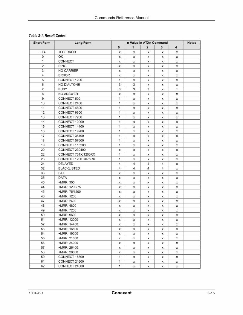
Commands Reference Manual
100498D Conexant 3-15
Table 3-1. Result CodesShort Form Long Form n Value in ATXn Command Notes
0 1 2 3 4
+F4 +FCERROR x x x x x
0 OK x x x x x
1 CONNECT x x x x x
2 RING x x x x x
3 NO CARRIER x x x x x
4 ERROR x x x x x
5 CONNECT 1200 1 x x x x
6 NO DIALTONE 3 3 x x x
7 BUSY 3 3 3 x x
8 NO ANSWER x x x x x
9 CONNECT 600 1 x x x x
10 CONNECT 2400 1 x x x x
11 CONNECT 4800 1 x x x x
12 CONNECT 9600 1 x x x x
13 CONNECT 7200 1 x x x x
14 CONNECT 12000 1 x x x x
15 CONNECT 14400 1 x x x x
16 CONNECT 19200 1 x x x x
17 CONNECT 38400 1 x x x x
18 CONNECT 57600 1 x x x x
19 CONNECT 115200 1 x x x x
20 CONNECT 230400 x x x x x
22 CONNECT 75TX/1200RX 1 x x x x
23 CONNECT 1200TX/75RX 1 x x x x
24 DELAYED 4 4 4 4 x
32 BLACKLISTED 4 4 4 4 x
33 FAX x x x x x
35 DATA x x x x x
40 +MRR: 300 x x x x x
44 +MRR: 1200/75 x x x x x
45 +MRR: 75/1200 x x x x x
46 +MRR: 1200 x x x x x
47 +MRR: 2400 x x x x x
48 +MRR: 4800 x x x x x
49 +MRR: 7200 x x x x x
50 +MRR: 9600 x x x x x
51 +MRR: 12000 x x x x x
52 +MRR: 14400 x x x x x
53 +MRR: 16800 x x x x x
54 +MRR: 19200 x x x x x
55 +MRR: 21600 x x x x x
56 +MRR: 24000 x x x x x
57 +MRR: 26400 x x x x x
58 +MRR: 28800 x x x x x
59 CONNECT 16800 1 x x x x
61 CONNECT 21600 1 x x x x
62 CONNECT 24000 1 x x x x
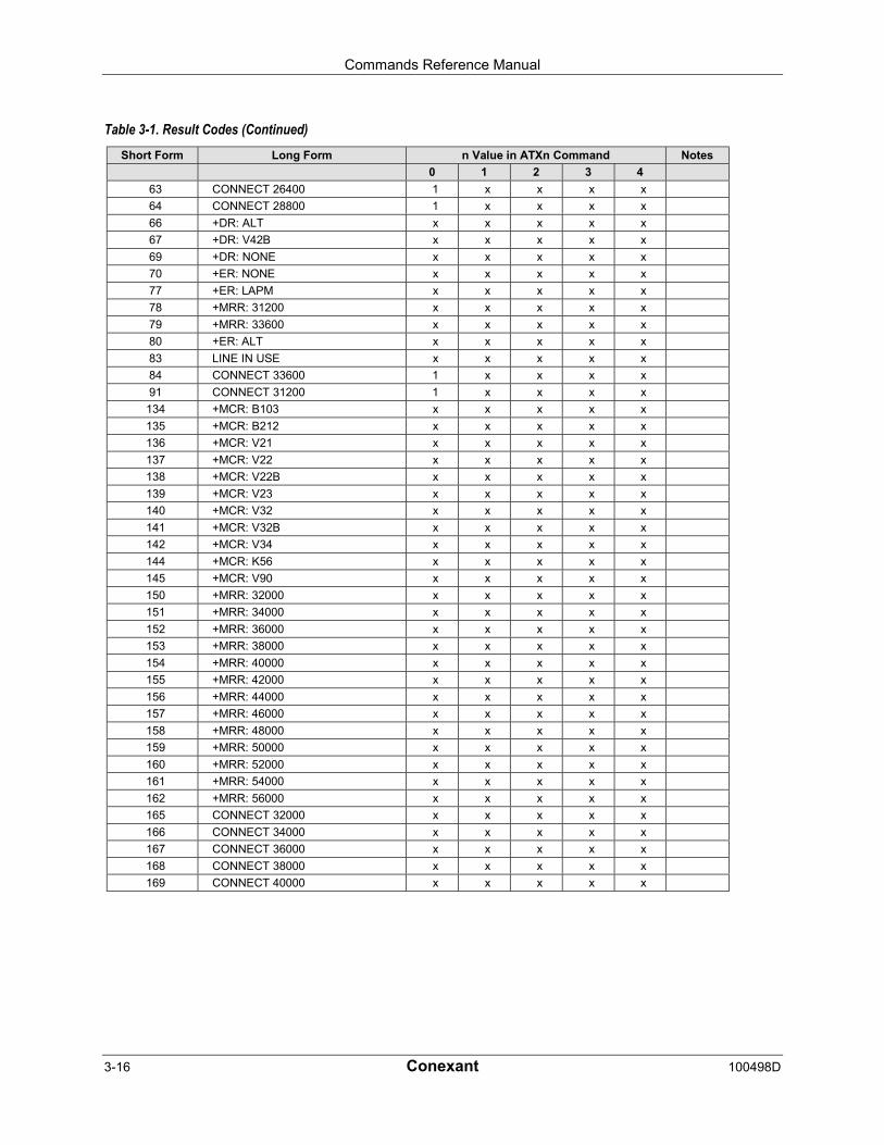
Commands Reference Manual
3-16 Conexant 100498D
Table 3-1. Result Codes (Continued)Short Form Long Form n Value in ATXn Command Notes
0 1 2 3 4
63 CONNECT 26400 1 x x x x
64 CONNECT 28800 1 x x x x
66 +DR: ALT x x x x x
67 +DR: V42B x x x x x
69 +DR: NONE x x x x x
70 +ER: NONE x x x x x
77 +ER: LAPM x x x x x
78 +MRR: 31200 x x x x x
79 +MRR: 33600 x x x x x
80 +ER: ALT x x x x x
83 LINE IN USE x x x x x
84 CONNECT 33600 1 x x x x
91 CONNECT 31200 1 x x x x
134 +MCR: B103 x x x x x
135 +MCR: B212 x x x x x
136 +MCR: V21 x x x x x
137 +MCR: V22 x x x x x
138 +MCR: V22B x x x x x
139 +MCR: V23 x x x x x
140 +MCR: V32 x x x x x
141 +MCR: V32B x x x x x
142 +MCR: V34 x x x x x
144 +MCR: K56 x x x x x
145 +MCR: V90 x x x x x
150 +MRR: 32000 x x x x x
151 +MRR: 34000 x x x x x
152 +MRR: 36000 x x x x x
153 +MRR: 38000 x x x x x
154 +MRR: 40000 x x x x x
155 +MRR: 42000 x x x x x
156 +MRR: 44000 x x x x x
157 +MRR: 46000 x x x x x
158 +MRR: 48000 x x x x x
159 +MRR: 50000 x x x x x
160 +MRR: 52000 x x x x x
161 +MRR: 54000 x x x x x
162 +MRR: 56000 x x x x x
165 CONNECT 32000 x x x x x
166 CONNECT 34000 x x x x x
167 CONNECT 36000 x x x x x
168 CONNECT 38000 x x x x x
169 CONNECT 40000 x x x x x

Commands Reference Manual
100498D Conexant 3-17
Table 3-1. Result Codes (Continued)Short Form Long Form n Value in ATXn Command Notes
0 1 2 3 4
170 CONNECT 42000 x x x x x
171 CONNECT 44000 x x x x x
172 CONNECT 46000 x x x x x
173 CONNECT 48000 x x x x x
174 CONNECT 50000 x x x x x
175 CONNECT 52000 x x x x x
176 CONNECT 54000 x x x x x
177 CONNECT 56000 x x x x x
178 CONNECT 230400 x x x x x
180 CONNECT 28000 x x x x x
181 CONNECT 29333 x x x x x
182 CONNECT 30667 x x x x x
183 CONNECT 33333 x x x x x
184 CONNECT 34667 x x x x x
185 CONNECT 37333 x x x x x
186 CONNECT 38667 x x x x x
187 CONNECT 41333 x x x x x
188 CONNECT 42667 x x x x x
189 CONNECT 45333 x x x x x
190 CONNECT 46667 x x x x x
191 CONNECT 49333 x x x x x
192 CONNECT 50667 x x x x x
193 CONNECT 53333 x x x x x
194 CONNECT 54667 x x x x x
195 +MRR: 28000 x x x x x
196 +MRR: 29333 x x x x x
197 +MRR: 30667 x x x x x
198 +MRR: 33333 x x x x x
199 +MRR: 34667 x x x x x
200 +MRR: 37333 x x x x x
201 +MRR: 38667 x x x x x
202 +MRR: 41333 x x x x x
203 +MRR: 42667 x x x x x
204 +MRR: 45333 x x x x x
205 +MRR: 46667 x x x x x
206 +MRR: 49333 x x x x x
207 +MRR: 50667 x x x x x
208 +MRR: 53333 x x x x x
209 +MRR: 54667 x x x x x
Notes:
1. An 'x' in a column indicates that the message (either the long form if verbose, or the value only for short form) willbe generated when that particular value of 'n' (shown at the top of the column) has been selected by the use ofATXn. If the column is blank, then no message will be generated for that x option. A numeral indicates which lessexplicit message (verbose or short form) will be output for that X option. (Also, see Section 3.3).
Commands Reference Manual
3-18 Conexant 100498D
&C - RLSD Behavior
This parameter determines how the state of the Received Line Signal Detector (RLSD) outputrelates to the detection of received line signal from the distant end. Changing the parameterwill take effect immediately in both the command and online command states.
In &C1 mode of operation, RLSD is not turned off until all data previously received from theremote modem is delivered to the local DTE. However, such buffered data will be discardedand RLSD will be turned off if the DTE turns off DTR (if &D1 or &D2 is set).
Syntax
&C[<value>]
Defined Values
<value> Decimal number corresponding to the selected option.
0 RLSD is always ON.
1 RLSD follows the state of the carrier. (Default.)
Result Code
OK <value> = 0 or 1
ERROR Otherwise.
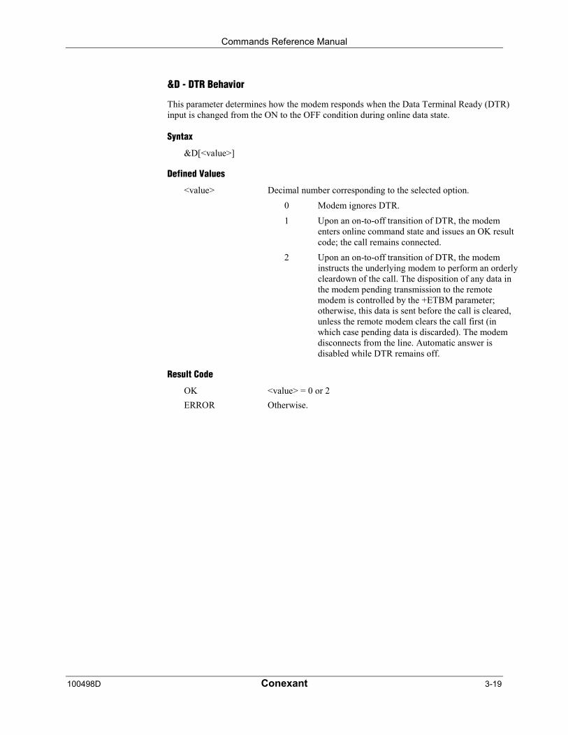
Commands Reference Manual
100498D Conexant 3-19
&D - DTR Behavior
This parameter determines how the modem responds when the Data Terminal Ready (DTR)input is changed from the ON to the OFF condition during online data state.
Syntax
&D[<value>]
Defined Values
<value> Decimal number corresponding to the selected option.
0 Modem ignores DTR.
1 Upon an on-to-off transition of DTR, the modementers online command state and issues an OK resultcode; the call remains connected.
2 Upon an on-to-off transition of DTR, the modeminstructs the underlying modem to perform an orderlycleardown of the call. The disposition of any data inthe modem pending transmission to the remotemodem is controlled by the +ETBM parameter;otherwise, this data is sent before the call is cleared,unless the remote modem clears the call first (inwhich case pending data is discarded). The modemdisconnects from the line. Automatic answer isdisabled while DTR remains off.
Result Code
OK <value> = 0 or 2
ERROR Otherwise.

Commands Reference Manual
3-20 Conexant 100498D
&K - Flow Control
This command defines the DTE/DCE (terminal/modem) flow control mechanism.
Syntax
&K[<value>]
Defined Values
<value> Decimal number corresponding to the selected option.
0 Disables flow control.
3 Enables RTS/CTS flow control. (Default for datamodem modes.)
4 Enables XON/XOFF flow control.
5 Included for compatibility only and has no effectother than returning an OK result code.
6 Included for compatibility only and has no effectother than returning an OK result code.
Result Codes
OK <value> = 0, 3, 4, 5, or 6.
ERROR Otherwise.
&M - Asynchronous/Synchronous Mode Selection
This command is included for compatibility only and has no effect other than returning aresult code. The only valid values are 0-3.
Syntax
&M[<mode>]
Defined Values
<mode > Decimal number corresponding to the selected value: 0-3.
Result Codes
OK <mode> = 0 to 3.
ERROR Otherwise.

Commands Reference Manual
100498D Conexant 3-21
&Q - Sync/Async Mode
This command determines the DTR operating mode. (Also, see \N.)
NOTE: When the &Q0 is issued to select the mode, the subsequent connect message willreport the DCE speed regardless of the W command and S95 settings.
Syntax
&Q[<mode>]
Defined Values
<mode > Decimal number corresponding to the selected mode:
0 Selects asynchronous operation in normal mode(speed buffering)
1 Selects asynchronous operation in normal mode(speed buffering)
2 Selects asynchronous operation in normal mode(speed buffering)
3 Selects asynchronous operation in normal mode(speed buffering)
5 Selects asynchronous operation in error correctionmode
6 Selects asynchronous operation in normal mode(speed buffering)
Result Codes
OK <mode > = 0-3, 5, 6.
ERROR Otherwise.
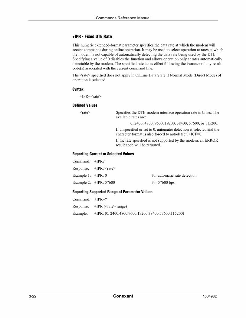
Commands Reference Manual
3-22 Conexant 100498D
+IPR - Fixed DTE Rate
This numeric extended-format parameter specifies the data rate at which the modem willaccept commands during online operation. It may be used to select operation at rates at whichthe modem is not capable of automatically detecting the data rate being used by the DTE.Specifying a value of 0 disables the function and allows operation only at rates automaticallydetectable by the modem. The specified rate takes effect following the issuance of any resultcode(s) associated with the current command line.
The <rate> specified does not apply in OnLine Data State if Normal Mode (Direct Mode) ofoperation is selected.
Syntax
+IPR=<rate>
Defined Values
<rate> Specifies the DTE-modem interface operation rate in bits/s. Theavailable rates are:
0, 2400, 4800, 9600, 19200, 38400, 57600, or 115200.
If unspecified or set to 0, automatic detection is selected and thecharacter format is also forced to autodetect, +ICF=0.
If the rate specified is not supported by the modem, an ERRORresult code will be returned.
Reporting Current or Selected Values
Command: +IPR?
Response: +IPR: <rate>
Example 1: +IPR: 0 for automatic rate detection.
Example 2: +IPR: 57600 for 57600 bps.
Reporting Supported Range of Parameter Values
Command: +IPR=?
Response: +IPR (<rate> range)
Example: +IPR: (0, 2400,4800,9600,19200,38400,57600,115200)
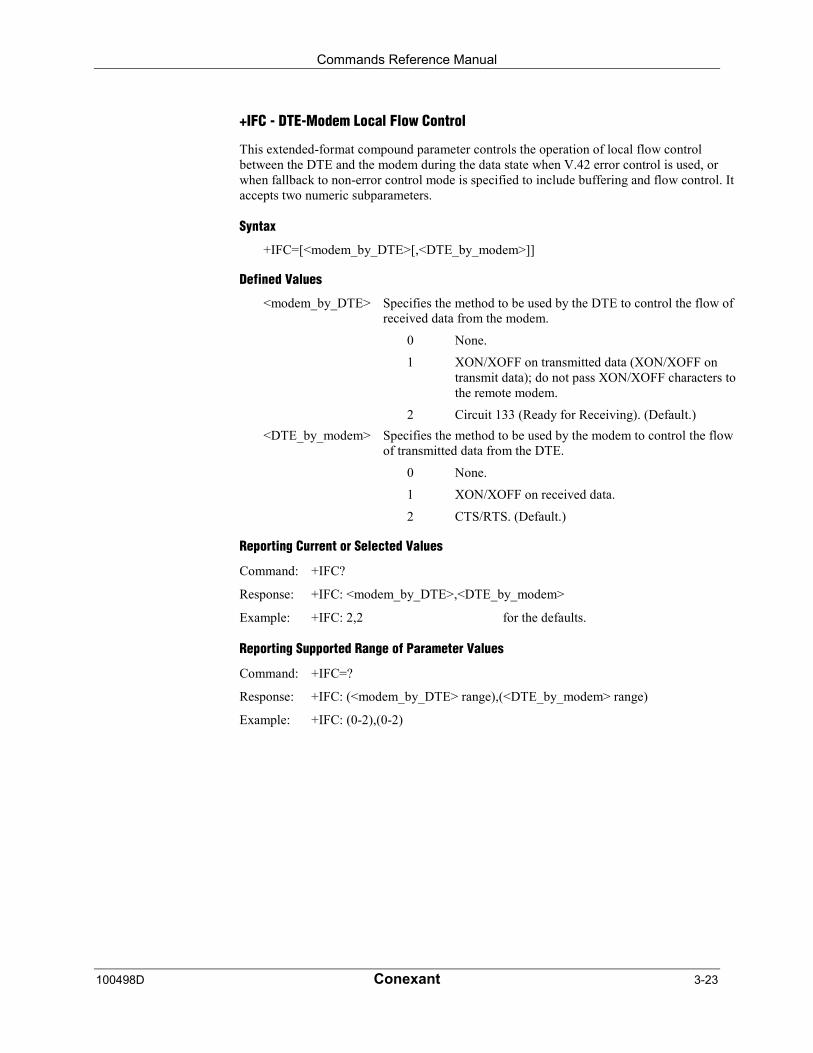
Commands Reference Manual
100498D Conexant 3-23
+IFC - DTE-Modem Local Flow Control
This extended-format compound parameter controls the operation of local flow controlbetween the DTE and the modem during the data state when V.42 error control is used, orwhen fallback to non-error control mode is specified to include buffering and flow control. Itaccepts two numeric subparameters.
Syntax
+IFC=[<modem_by_DTE>[,<DTE_by_modem>]]
Defined Values
<modem_by_DTE> Specifies the method to be used by the DTE to control the flow ofreceived data from the modem.
0 None.
1 XON/XOFF on transmitted data (XON/XOFF ontransmit data); do not pass XON/XOFF characters tothe remote modem.
2 Circuit 133 (Ready for Receiving). (Default.)
<DTE_by_modem> Specifies the method to be used by the modem to control the flowof transmitted data from the DTE.
0 None.
1 XON/XOFF on received data.
2 CTS/RTS. (Default.)
Reporting Current or Selected Values
Command: +IFC?
Response: +IFC: <modem_by_DTE>,<DTE_by_modem>
Example: +IFC: 2,2 for the defaults.
Reporting Supported Range of Parameter Values
Command: +IFC=?
Response: +IFC: (<modem_by_DTE> range),(<DTE_by_modem> range)
Example: +IFC: (0-2),(0-2)
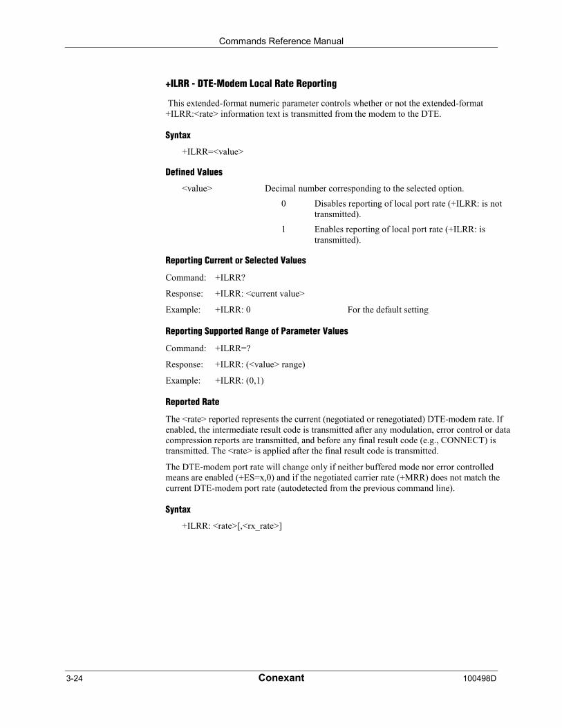
Commands Reference Manual
3-24 Conexant 100498D
+ILRR - DTE-Modem Local Rate Reporting
This extended-format numeric parameter controls whether or not the extended-format+ILRR:<rate> information text is transmitted from the modem to the DTE.
Syntax
+ILRR=<value>
Defined Values
<value> Decimal number corresponding to the selected option.
0 Disables reporting of local port rate (+ILRR: is nottransmitted).
1 Enables reporting of local port rate (+ILRR: istransmitted).
Reporting Current or Selected Values
Command: +ILRR?
Response: +ILRR: <current value>
Example: +ILRR: 0 For the default setting
Reporting Supported Range of Parameter Values
Command: +ILRR=?
Response: +ILRR: (<value> range)
Example: +ILRR: (0,1)
Reported Rate
The <rate> reported represents the current (negotiated or renegotiated) DTE-modem rate. Ifenabled, the intermediate result code is transmitted after any modulation, error control or datacompression reports are transmitted, and before any final result code (e.g., CONNECT) istransmitted. The <rate> is applied after the final result code is transmitted.
The DTE-modem port rate will change only if neither buffered mode nor error controlledmeans are enabled (+ES=x,0) and if the negotiated carrier rate (+MRR) does not match thecurrent DTE-modem port rate (autodetected from the previous command line).
Syntax
+ILRR: <rate>[,<rx_rate>]

Commands Reference Manual
100498D Conexant 3-25
Defined Values
<rate> Decimal value representing the current (negotiated or renegotiated)DTE-modem rate:
0, 300, 1200, 2400, 4800, 9600, 19200, 38400, 57600, or115200
<rx_rate> Optional decimal value reporting the RXD rate, if it is differentfrom the TXD rate:
0, 300, 1200, 2400, 4800, 9600, 19200, 38400, 57600, or115200
Example
+ILRR: 19200
3.2.3 Call Control
D - Dial
This command directs the modem to go on-line, dial according to the entered string andattempt to establish a connection. If no dial string is supplied, the modem will go on-line andattempt the handshake in originate mode. NOTE: If the ATD command is issued before theS1 register has cleared, the modem will respond with the NO CARRIER result code.
If +FCLASS=0 is selected, the modem will behave as a data modem and will attempt toconnect to another data modem. The modem will have up to the period of time specified byregister S6 or S7 to wait for carrier and complete the handshake. If this time expires beforethe modem can complete the handshake, the modem will go on-hook with the NO CARRIERresponse. This command will be aborted upon receipt of any DTE character beforecompletion of the handshake.
If +FCLASS=1 or 1.0 is selected, the modem will behave as a facsimile modem and attemptto connect to a facsimile machine (or modem) by entering the HDLC V.21 channel 2 receivestate (as if +FRH=3 had been issued). This command will be aborted upon receipt of any DTEcharacter if the modem has not finished dialing. In this case, the modem will go on-hook andreturn to command mode after displaying the NO CARRIER message. If the modem finishesdialing, it will proceed as if the +FRH=3 command is issued. (Refer to the +FRH command todetermine how the modem behaves following this stage.)
Syntax
D<modifier>
Defined Values
<modifier> The valid dial string parameters (modifiers) are described below.Punctuation characters may be used for clarity, with parentheses,hyphen, and spaces ignored.
0-9 DTMF digits 0 to 9.
A-D DTMF digits A, B, C, and D. Some countries may prohibit sendingof these digits during dialing.
L Re-dial last number: the modem will re-dial the last validtelephone number. The L must be immediately after the D with allthe following characters ignored).

Commands Reference Manual
3-26 Conexant 100498D
P Select pulse dialing: pulse dial the numbers that follow until a "T"is encountered. Affects current and subsequent dialing. Somecountries prevent changing dialing modes after the first digit isdialed.
T Select tone dialing: tone dial the numbers that follow until a "P" isencountered. Affects current and subsequent dialing. Somecountries prevent changing dialing modes after the first digit isdialed.
W Wait for dial tone: the modem will wait for dial tone before dialingthe digits following "W". If dial tone is not detected within thetime specified by S7 or S6, the modem will abort the rest of thesequence, return on-hook, and generate an error message.
* The 'star' digit (tone dialing only).
# The 'gate' digit (tone dialing only).
+
! Flash: the modem will go on-hook for a time defined by the valueof S29. Country requirements may limit the time imposed.
@ Wait for silence: the modem will wait for at least 5 seconds ofsilence in the call progress frequency band before continuing withthe next dial string parameter. If the modem does not detect these 5seconds of silence before the expiration of the call abort timer (S7),the modem will terminate the call attempt with a NO ANSWERmessage. If busy detection is enabled, the modem may terminatethe call with the BUSY result code. If answer tone arrives duringexecution of this parameter, the modem will handshake.
$ Wait for credit card dialing tone before continuing with the dialstring. If the tone is not detected within the time specified by S7 orS6, the modem will abort the rest of the sequence, return on-hook,and generate an error message.
& Wait for credit card dialing tone before continuing with the dialstring. If the tone is not detected within the time specified by S7 orS6, the modem will abort the rest of the sequence, return on-hook,and generate an error message.
, Dial pause: the modem will pause for a time specified by S8 beforedialing the digits following ",".
; Return to command state. Added to the end of a dial string. Thiscauses the modem to return to the command state after it processesthe portion of the dial string preceding the ";". This allows the userto issue additional commands while remaining off-hook. Theadditional commands may be placed in the original command linefollowing the ";" and/or may be entered on subsequent commandlines. The modem will enter call progress only after an additionaldial command is issued without the ";" terminator. Use "H" toabort the dial in progress, and go back on-hook.
^ Toggles calling tone enable/disable: applicable to current dialattempt only.
( ) Ignored: may be used to format the dial string.
- Ignored: may be used to format the dial string.
<space> Ignored: may be used to format the dial string.
Commands Reference Manual
100498D Conexant 3-27
T - Set Tone Dial Default
This command forces DTMF dialing until the next P dial modifier or P command is received.The modem will set an S-Parameter bit to indicate that all subsequent dialing should beconducted in tone mode. Note that the DP command will override this command. Clears S14bit 5.
This command may not be permitted in some countries. (See P.)
Syntax
T
Result Codes
OK
P - Set Pulse Dial Default
This command forces pulse dialing until the next T dial modifier or T command is received.Sets S14 bit 5.
As soon as a dial command is executed which explicitly specifies the dialing mode for thatparticular call (e.g., ATDT..), this command is overridden so that all future dialing will betone dialed. (See T command.)
This command may not be permitted in some countries.
A - Answer
The modem will go off-hook and will attempt to answer an incoming call if correct conditionsare met. Upon successful completion of answer handshake, the modem will go on-line inanswer mode. This command may be affected by the state of Line Current Sense, if enabled.(Most countries do not require Line Current Sense.) Operation is also dependent upon+FCLASS command and country-specific requirements.
If +FCLASS=0 is selected, the modem will enter the connect state after exchanging carrierwith the remote modem. If no carrier is detected within a period specified in register S7, themodem will hang up. Any character entered during the connect sequence will abort theconnection attempt.
If +FCLASS=1.0 is selected, the modem will go off-hook in V.21 answer mode. It willgenerate the V.21 2100 Hz answer tone for 3 ± 0.5 seconds. Following a delay of 70 ms, itwill proceed as if the +FTH=3 command were issued. At any stage up to (but excluding) the+FTH=3 command state, any character will abort the communication. (See the description ofthe +FTH command for details.)
Commands Reference Manual
3-28 Conexant 100498D
H - Disconnect (Hang-Up)
This command initiates a hang up sequence. This command may not be available for somecountries due to PTT restrictions.
Syntax
H[<value>]
Defined Values
<value> Decimal number corresponding to the selected option.
0 The modem will release the line if the modem iscurrently on-line.
1 If on-hook, the modem will go off-hook and remainin command mode.
Result Codes
OK <value> = 0 or 1.
ERROR Otherwise.
O - Return to On-Line Data Mode
This command specifies that the modem will enter the on-line data mode from the on-linecommand mode with or without a retrain. If in the off-line command mode when thiscommand is entered, the modem reports ERROR.
Syntax
O[<value>]
Defined Values
<value> Decimal number corresponding to the selected option.
0 Enters on-line data mode from the on-line commandmode without a retrain. Handling is determined bythe Call Establishment task. Generally, if aconnection exists, this command connects the DTEback to the remote modem after an escape (+++).
1 Performs a retrain then enters on-line data mode fromthe on-line command mode.
Result Codes
OK <value> = 0 or 1 and a connection exists.
ERROR Otherwise or no connection exists.

Commands Reference Manual
100498D Conexant 3-29
L - Speaker Volume
This command sets the speaker volume control according to the parameter supplied.
Syntax
L[<value>]
Defined Values
<value> Decimal number corresponding to the selected option.
0 Off.
1 Low volume. (Default.)
2 Medium volume.
3 High volume.
Result Codes
OK <value> = 0 to 3.
ERROR Otherwise.
M - Speaker Control
This command controls speaker on or off according to the supplied parameter.
Syntax
M[<value>]
Defined Values
<value> Decimal number corresponding to the selected option.
0 Speaker off.
1 Speaker on during call establishment, but off whenreceiving carrier. (Default.)
2 Speaker on.
3 Speaker is off when receiving carrier and duringdialing, but on during answering.
Result Codes
OK <value> = 0 to 3.
ERROR Otherwise.
Commands Reference Manual
3-30 Conexant 100498D
&G - Select Guard Tone
This command is included for compatibility only and has no effect other than returning anOK result code.
Syntax
&G[<value>]
Defined Values
<value> Decimal number corresponding to the selected option.
0 Included for compatibility only and has no effectother than returning an OK result code. (Default.)
1 Included for compatibility only and has no effectother than returning an OK result code.
2 Included for compatibility only and has no effectother than returning an OK result code.
Result Code
OK <value> = 0 to 2.
ERROR Otherwise.
&P - Select Pulse Dial Make/Break Ratio
This command determines the make/break ratio used during pulse dialing. It is only effectiveif the appropriate bit to enable this command is set through the .INF File. If enabled, it willoverride the make/break ratios in the OEM parameters in the .INF File. The default iscountry-dependent.
Syntax
&P[<value>]
Defined Values
<value> Decimal number corresponding to the selected information.
0 Selects 39%-61% make/break ratio at 10 pulses persecond. (Default.)
1 Selects 33%-67% make/break ratio at 10 pulses persecond.
2 Selects 39%-61% make/break ratio at 20 pulses persecond.
3 Selects 33%-67% make/break ratio at 20 pulses persecond.
Result Codes
OK <value> = 0 to 3.
ERROR Otherwise.

Commands Reference Manual
100498D Conexant 3-31
&V - Display Current Configuration and Stored Profile
This command reports the current (active) configuration and the stored (user) profiles.
Syntax
&V
Result Code
OK
Example:AT&VACTIVE PROFILE:E1 L1 M1 Q0 T V1 X0 &C1 &D2 &G0 &T0S00:000 S01:000 S02:043 S03:013 S04:010 S05:008 S06:004S07:050 S08:004S10:014 S12:050 S16:000 S18:000 S29:070
STORED PROFILE 0:E1 L1 M1 Q0 T V1 X4 &C1 &D2 &G0 &T0S00:000 S02:043 S06:004 S07:050 S08:004 S10:014 S12:050S18:000 S29:070
OK
&W - Store Current Configuration
This command saves the current (active) configuration (profile), including S-Parameters, inthe Registry. The current configuration is comprised of a list of storable parameters illustratedin the &V command. These settings are restored to the active configuration upon receiving anZ command or at power up.
Syntax
&W
Result Code
OK

Commands Reference Manual
3-32 Conexant 100498D
*B - Display Blacklisted Numbers
This command requests the modem to return a list of blacklisted numbers to the DTE. Theformat of the response is shown by the example below. Permanently forbidden numbers asdefined by country requirements will not appear on this list. If no numbers are blacklisted,only the OK result code is issued.
Example:
NO. - PHONE NUMBER -
------ ------------------------------
1; 41755376602; 82889249613; 38872788624; 31248394425; 6284664
OK
*D - Display Delayed Numbers
This command causes the modem to send a list of the delayed numbers together with thedelay associated with each. The modem will return a list of delayed telephone numbers asdefined in the *B command. The format of the response is shown by the example below(delay times are shown as hours:minutes:seconds). If no numbers are delayed, only the OKresult code is issued.
Example:
NO. - PHONE NUMBER -DELAY
------ -------------------------------------------
1; 8264734660 2:00:002; 7532634661 2:00:003; 2587334662 0:02:004; 7532651663 0:03:255; 7459931664 0:01:45
OK

Commands Reference Manual
100498D Conexant 3-33
3.2.4 Modulation Control Commands
+MS - Modulation Selection
This extended-format compound parameter controls the manner of operation of themodulation capabilities in the modem. It accepts six subparameters.
Syntax
+MS=[<carrier>[,<automode>[,<min_tx_rate>[,<max_tx_rate>[,<min_rx_rate>[,<max_rx_rate>]]]]]]
Where: Possible <carrier>, <min_tx_rate>, <max_tx_rate>,<min_rx_rate>, and <max_rx_rate> values are listed in Table 3-2.
Table 3-2. +MS Command Supported RatesModulation <carrier> Possible (<min_rx_rate>, <min_rx_rate>, (<min_tx_rate>),
and <max_tx_rate>) Rates (bps)
Bell 103 B103 300
Bell 212 B212 1200 Rx/75 Tx or 75 Rx/1200 Tx
V.21 V21 300
V.22 V22 1200
V.22 bis V22B 2400 or 1200
V.23 V23C 1200
V.32 V32 9600 or 4800
V.32 bis V32B 14400, 12000, 9600, 7200, or 4800
V.34 V34 33600, 31200, 28800, 26400, 24000, 21600, 19200, 16800,14400, 12000, 9600, 7200, 4800, or 2400
K56flex K56 56000, 54000, 52000, 50000, 48000, 46000, 44000, 42000,40000, 38000, 36000, 34000, 32000
V.90 V90 56000, 54667, 53333, 52000, 50667, 49333, 48000, 46667,45333, 44000, 42667, 41333, 40000, 38667, 37333, 36000,34667, 33333, 32000, 30667, 29333, 28000
V.92 downstream V92 56000, 54667, 53333, 52000, 50667, 49333, 48000, 46667,45333, 44000, 42667, 41333, 40000, 38667, 37333, 36000,34667, 33333, 32000, 30667, 29333, 28000
V.92 upstream V92 48000, 46667, 45333, 44000, 42667, 41333, 40000, 38667,37333, 36000, 34667, 33333, 32000, 30667, 29333, 28000,26667, 25333, 24000
Commands Reference Manual
3-34 Conexant 100498D
Defined Values
<carrier> A string which specifies the preferred modem carrier to use inoriginating or answering a connection. <carrier> values are stringsof up to eight characters, consisting only of numeric digits andupper case letters. <carrier> values for ITU standard modulationstake the form: <letter><1-4 digits><other letters as needed>.Defined values are listed in Table 3-1.
<automode> A numeric value which enables or disables automatic modulationnegotiation (e.g., ITU-T V.32bis Annex A or V.8).
0 Automode disabled.
1 Automode enabled. (Default.)
<min_rx_rate> and
<max_rx_rate> Numeric values which specify the lowest (<min_rx_rate>) andhighest (<max_rx_rate>) rate at which the modem may establish areceive connection. May be used to condition distinct limits for thereceive direction as distinct from the transmit direction. Values forthis subparameter are decimal encoded, in units of bit/s. Thepossible values for each modulation are listed in Table 3-1. Actualvalues will be limited to possible values corresponding to theentered <carrier> and fall-back <carrier> as determined duringoperation. (Default = lowest (<min_rx_rate>) and highest(<max_rx_rate>) rate supported by the selected carrier.)
<min_tx_rate> and
<max_tx_rate> Numeric values which specify the lowest (<min_tx_rate>) andhighest (<max_tx_rate>) rate at which the modem may establish atransmit connection. Non-zero values for this subparameter aredecimal encoded, in units of bit/s. The possible values for eachmodulation are listed in Table 3-1. Actual values will be limited topossible values corresponding to the entered <carrier> and fall-back <carrier> as determined during operation. (Default = lowest(<min_tx_rate>) and highest (<max_tx_rate>) rate supported bythe selected carrier.)
Commands Reference Manual
100498D Conexant 3-35
Reporting Current or Selected Values
Command: +MS?
Response: +MS:<carrier>,<automode>,<min_tx_rate>,<max_tx_rate>,<min_rx_rate>,<max_rx_rate>
Note: The current active settings are reported under control of the +MR parameter.
Example: +MS: K56, 1,75,33600,75,56000
For default values. This example allows maximum system flexibility todetermine optimal receive and transmit rates during operation.
Reporting Supported Range of Parameter Values
Command: +MS=?
Response: +MS: (<carrier> range),(<automode> range),(<min_tx_rate> range),(<max_tx_rate> range),(<min_rx_rate> range), (<max_rx_rate> range)
Example: +MS: (B103,B212,V21,V22,V22B,V23C,V32,V32B,V34,K56,V90),(0,1),(75-33600),(75-33600),(75-56000),(75-56000)
Result Code
OK Valid subparameter string
ERROR Otherwise.

Commands Reference Manual
3-36 Conexant 100498D
+MR - Modulation Reporting Control
This extended-format numeric parameter controls whether or not the extended-format +MCR:<carrier> and +MRR: <rate> intermediate result codes are transmitted from the modem to theDTE (see Section 3.5 and Table 3-14). If enabled, +MCR: <carrier> and +MRR: <rate>intermediate result codes represent the current (negotiated or renegotiated) modulation<carrier> and <rate> that are transmitted at the point during connect negotiation(handshaking) at which the modem has determined which modulation and rate will be used,i.e., before any Error Control or Data Compression reports are transmitted, and before anyfinal result code (e.g., CONNECT) is transmitted.
S95 bit 2 is reset to 0 for +MR=0 and is set to a 1 for +MR=1 or +MR=2. The more recentsetting of +MR or S95 bit 2, and the W command setting, determines modulation result codereporting (see S95 Parameter and W Command).
Syntax
+MR=[<value>]
Defined Values
<value> A decimal number corresponding to the selected option:
0 Disables reporting of modulation connection (+MCR:and +MRR: are not transmitted).
1 Enables reporting of modulation connection (+MCR:and +MRR: are transmitted). (Default.)
2 Enables reporting of modulation connection (+MCR:and Receive Rate Only: are transmitted).
Reporting Current or Selected Values
Command: +MR?
Response: +MR: <current value>
Example: +MR: 1 For default setting
Reporting Supported Range of Parameter Values
Command: +MR=?
Response: +MR: (<value>range)
Example: +MR: (0,1,2)

Commands Reference Manual
100498D Conexant 3-37
+MCR: Report Syntax
Response: +MCR: <carrier>
<carrier> Alphanumeric code corresponding to the reported carrier. Definedvalues are:
B103 For Bell 103
B212 For Bell 212
V21 For V.21
V22 For V.22
V22B For V.22bis
V23C For V.23
V32 For V.32
V32B For V.32bis
V34 For V.34
K56 For K56flex
V90 For V.90
V92 For V.92
+MRR: Report Syntax
Response: +MRR: <tx_rate>,<rx_rate>
<tx_rate> Decimal transmit rate in bits/s.
<rx_rate> Decimal receive rate in bits/s.
Example: +MRR: 28800, 48000
%E - Enable/Disable Line Quality Monitor, Auto-Retrain, and Auto-RateRenegotiation
This command controls whether or not the modem will automatically monitor the line qualityand request a retrain (%E1) or a rate renegotiation when line quality merits a change. Ifenabled, the modem attempts to retrain for a maximum of 30 seconds.
Syntax
%E[<value>]
Defined Values
<value> A decimal number corresponding to the selected option:
0 Disable line quality monitor, auto-retrain, and auto-rate renegotiation.
1 Enable line quality monitor, auto-retrain, and auto-rate renegotiation. (Default.)
Result Code
OK <value> = 0 and 1
ERROR Otherwise.
Commands Reference Manual
3-38 Conexant 100498D
3.2.5 Error Control Commands
This section describes parameters used to select and operate the modem in V.42 LAPM orMNP error control mode, Normal (Buffered) Mode, or V.80 Synchronous Access Mode.
+ES - Error Control and Synchronous Mode Selection
This extended-format command specifies the initial requested mode of operation when themodem is operating as the originator, optionally specifies the acceptable fallback mode ofoperation when the modem is operating as the originator, and optionally specifies theacceptable fallback mode of operation when the modem is operating as the answerer. Itaccepts three numeric subparameters:
Syntax
+ES=[<orig_rqst>[,<orig_fbk>[,<ans_fbk>]]]
Defined Values
<orig_rqst> Decimal number which specifies the initial requested mode ofoperation when the modem is operating as the originator. Theoptions are:
0 Initiate call with Direct Mode.
1 Initiate call with Normal Mode (also referred to asBuffered Mode or Direct Mode) only.
2 Initiate V.42 without Detection Phase. If V.8 is inuse, disable V.42 Detection Phase.
3 Initiate V.42 with Detection Phase. (Default.)
4 Initiate MNP.
6 Initiate V.80 Synchronous Access Mode whenconnection is completed, and Data State is entered.(See +ESA and +ITF commands.)
<orig_fbk> Decimal number which specifies the acceptable fallback mode ofoperation when the modem is operating as the originator.
0 LAPM, MNP, or Normal Mode error controloptional. (Default.)
1 LAPM, MNP, or Direct Mode error control optional.
2 LAPM or MNP error control required; disconnect iferror control is not established.
3 LAPM error control required; disconnect if errorcontrol is not established.
4 MNP error control required; disconnect if errorcontrol is not established.

Commands Reference Manual
100498D Conexant 3-39
<ans_fbk> Decimal number which specifies the acceptable fallback mode ofoperation when the modem is operating as the answerer orspecifies V.80 Synchronous Access Mode.
1 Error control disabled, use Normal Mode.
2 LAPM, MNP, or Normal Mode error controloptional. (Default.)
3 LAPM, MNP, or Direct Mode error control optional.
4 LAPM or MNP error control required; disconnect iferror control is not established.
5 LAPM error control required; disconnect if errorcontrol is not established.
6 MNP error control required; disconnect if errorcontrol is not established.
8 Initiate V.80 Synchronous Access Mode whenconnection is completed, and Data State is entered(see +ESA and +ITF commands).
Examples
+ES=6 Enable V.80 Synchronous Access Mode originator
+ES=,,8 Enable V.80 Synchronous Access Mode answerer
+ES=6,,8 Enable V.80 Synchronous Access Mode originator and answerer
+ES=3 Enable V.42 with Detection Phase originator. Disable V.80 SynchronousAccess Mode originator.
+ES=,,2 Allow LAPM, MNP, or Normal Mode connection answerer. Disable V.80Synchronous Access Mode answerer.
+ES=3,,2 Enable V.42 with Detection Phase originator, allow LAPM, MNP, orNormal Mode connection answer. Disable Synchronous Access Modeoriginator and answerer.
Reporting Current or Selected Values
Command: +ES?
Response: +ES: <orig_rqst>,<orig_fbk>,<ans_fbk>
Example: +ES: 3,0,2 For default settings.
+ES: 6,0,8 For V.80 Synchronous Access Modeoriginator and answerer.
Reporting Supported Range of Parameter Values
Command: +ES=?
Response: +ES: (<orig_rqst> range),( <orig_fbk> range), (<ans_fbk> range)
Example: +ES: (0-4,6),(0-4),(0-6,8)
Commands Reference Manual
3-40 Conexant 100498D
+EB - Break Handling in Error Control Operation
This extended-format compound parameter controls the break handling in V.42 operation. Itaccepts three numeric subparameters:
Syntax
+EB=[<break_selection>[,<timed>[,<default_length>]]]
Defined Values
<break_selection> Decimal number 0 specifying that break is to be ignored, i.e., notsignaled to remote DCE.
<timed> Decimal number 0 specifying that any transmitted V.42 L-SIGNAL will not indicate break signal length
<default_length> Decimal number 0 specifying that break is not delivered to theDTE.
Reporting Current or Selected Values
Command: +EB?
Response: +EB: <break_selection>,<timed>,<default_length><CR>
Example: +EB: 0,0,0 For default settings.
Reporting Supported Range of Parameter Values
Command: +EB=?
Response: +EB: (<break_selection> range),(<timed> range), (default_length> range)
Example: +EB: (0),(0),(0)
+ESR - Selective Repeat
This extended-format numeric parameter controls the use of the selective repeat (SREJ)option in V.42.
Syntax
+ESR=[<value>].
Defined Values
<value> Decimal number 0 specifying that SREJ is not used.
Example:
+ESR:0 For default settings.

Commands Reference Manual
100498D Conexant 3-41
+EFCS - 32-bit Frame Check Sequence
This extended-format numeric parameter controls the use of the 16-bit or 32-bit frame checksequence (FCS) option in V.42.
Syntax
+EFCS=[<value>]
Defined Values
<value> Decimal number 0 specifying the use of the 16-bit FCS specifiedin V.42.
Reporting Current or Selected Values
Command: +EFCS?
Response: +EFCS: <value>
Example: +EFCS: 0 For default setting.
Reporting Supported Range of Parameter Values
Command: +EFCS=?
Response: +EFCS: (<value> range)
Example: +EFCS: (0)
Commands Reference Manual
3-42 Conexant 100498D
+ER - Error Control Reporting
This extended-format numeric parameter controls whether or not the extended-format "+ER: "intermediate result code is transmitted from the modem to the DTE (see Section 3.5 and Table3-15).
S95 bit 3 is reset to 0 for +ER=0 and is set to a 1 for +ER=1. The more recent setting of +ERor S95 bit 3, and the W command setting, determines the actual error control result codereporting (see S95 Parameter and W Command).
Syntax
+ER=[<value>]
Defined Values
<value> A decimal number corresponding to the selected error controloption:
0 Error control reporting disabled (no +ERintermediate result code transmitted).
1 Error control reporting enabled (+ER intermediateresult code transmitted). (Default.)
Reporting Current or Selected Values
Command: +ER?
Response: +ER: <current value>
Example: +ER: 1 for the default setting
Reporting Supported Range of Parameter Values
Command: +ER=?
Response: +ER: (<value> range)
Example: +ER: (0,1)
Commands Reference Manual
100498D Conexant 3-43
+ER: <type>+ER: <type>+ER: <type>+ER: <type>
The +ER: <type> reported represents the current (negotiated or renegotiated) modem-modemerror control type. If enabled, the intermediate result code is transmitted at the point duringerror control negotiation (handshaking) at which the modem has determined which errorcontrol protocol will be used (if any), before the final result code (e.g., CONNECT) istransmitted.
The +ER intermediate result code, if enabled, is issued after the Modulation report (+MCRand +MRR) and before the Data Compression Report (+DR).
Syntax
+ER: <type>
Defined Values
<type> An alphanumeric code corresponding to the selected protocol.
NONE Error control is not in use.
LAPM V.42 LAPM protocol is in use.
ALT MNP is in use.
Example
+ER: LAPM

Commands Reference Manual
3-44 Conexant 100498D
+ETBM - Call Termination Buffer Management
This extended-format compound parameter controls the handling of data remaining in modembuffers upon call termination. It accepts three numeric subparameters:
Syntax
+ETBM=[<pending_TD>[,<pending_RD>[,<timer>]]]
Defined Values
<pending_TD> Decimal number 0 specifying that disconnect will occurimmediately and all buffered transmit data will be discarded whenthe local DTE requests call disconnection.
<pending_RD> Decimal number 0 specifying that disconnect will occurimmediately and all buffered receive data will be discarded whenthe local DTE requests call disconnection.
<timer> Decimal number 0 specifying that the modem will not attempt todeliver the buffered data before abandoning the attempt anddiscarding remaining data.
Reporting Current or Selected Values
Command: +ETBM?
Response: +ETBM: <pending_TD>,<pending_RD>,<timer>
Example: +ETBM: 0,0,0
Reporting Supported Range of Parameter Values
Command: +ETBM=?
Response: +ETBM: (<pending_TD> range),(<pending_RD> range), (<timer> range)
Example: +ETBM: (0),(0),(0)
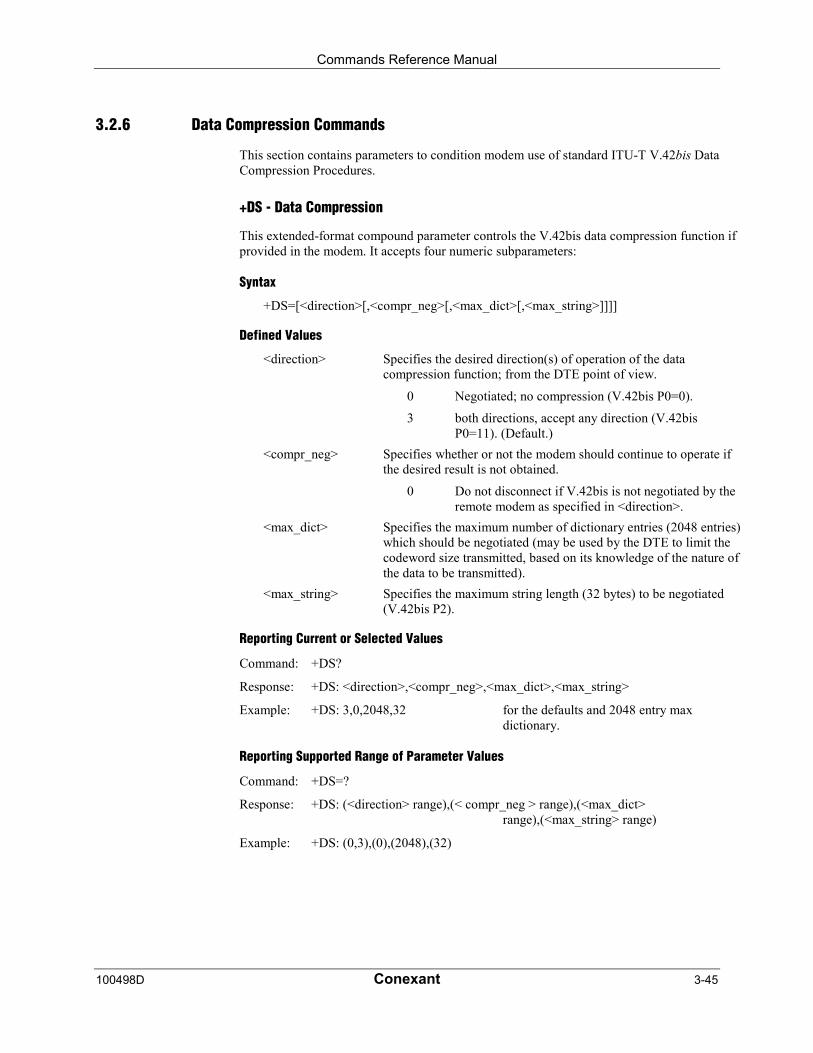
Commands Reference Manual
100498D Conexant 3-45
3.2.6 Data Compression Commands
This section contains parameters to condition modem use of standard ITU-T V.42bis DataCompression Procedures.
+DS - Data Compression
This extended-format compound parameter controls the V.42bis data compression function ifprovided in the modem. It accepts four numeric subparameters:
Syntax
+DS=[<direction>[,<compr_neg>[,<max_dict>[,<max_string>]]]]
Defined Values
<direction> Specifies the desired direction(s) of operation of the datacompression function; from the DTE point of view.
0 Negotiated; no compression (V.42bis P0=0).
3 both directions, accept any direction (V.42bisP0=11). (Default.)
<compr_neg> Specifies whether or not the modem should continue to operate ifthe desired result is not obtained.
0 Do not disconnect if V.42bis is not negotiated by theremote modem as specified in <direction>.
<max_dict> Specifies the maximum number of dictionary entries (2048 entries)which should be negotiated (may be used by the DTE to limit thecodeword size transmitted, based on its knowledge of the nature ofthe data to be transmitted).
<max_string> Specifies the maximum string length (32 bytes) to be negotiated(V.42bis P2).
Reporting Current or Selected Values
Command: +DS?
Response: +DS: <direction>,<compr_neg>,<max_dict>,<max_string>
Example: +DS: 3,0,2048,32 for the defaults and 2048 entry maxdictionary.
Reporting Supported Range of Parameter Values
Command: +DS=?
Response: +DS: (<direction> range),(< compr_neg > range),(<max_dict>range),(<max_string> range)
Example: +DS: (0,3),(0),(2048),(32)
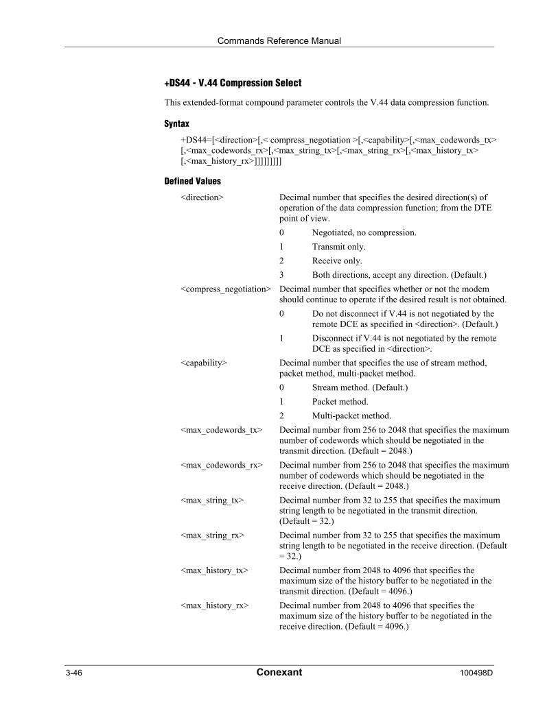
Commands Reference Manual
3-46 Conexant 100498D
+DS44 - V.44 Compression Select
This extended-format compound parameter controls the V.44 data compression function.
Syntax
+DS44=[<direction>[,< compress_negotiation >[,<capability>[,<max_codewords_tx>[,<max_codewords_rx>[,<max_string_tx>[,<max_string_rx>[,<max_history_tx>[,<max_history_rx>]]]]]]]]]
Defined Values
<direction> Decimal number that specifies the desired direction(s) ofoperation of the data compression function; from the DTEpoint of view.
0 Negotiated, no compression.
1 Transmit only.
2 Receive only.
3 Both directions, accept any direction. (Default.)
<compress_negotiation> Decimal number that specifies whether or not the modemshould continue to operate if the desired result is not obtained.
0 Do not disconnect if V.44 is not negotiated by theremote DCE as specified in <direction>. (Default.)
1 Disconnect if V.44 is not negotiated by the remoteDCE as specified in <direction>.
<capability> Decimal number that specifies the use of stream method,packet method, multi-packet method.
0 Stream method. (Default.)
1 Packet method.
2 Multi-packet method.
<max_codewords_tx> Decimal number from 256 to 2048 that specifies the maximumnumber of codewords which should be negotiated in thetransmit direction. (Default = 2048.)
<max_codewords_rx> Decimal number from 256 to 2048 that specifies the maximumnumber of codewords which should be negotiated in thereceive direction. (Default = 2048.)
<max_string_tx> Decimal number from 32 to 255 that specifies the maximumstring length to be negotiated in the transmit direction.(Default = 32.)
<max_string_rx> Decimal number from 32 to 255 that specifies the maximumstring length to be negotiated in the receive direction. (Default= 32.)
<max_history_tx> Decimal number from 2048 to 4096 that specifies themaximum size of the history buffer to be negotiated in thetransmit direction. (Default = 4096.)
<max_history_rx> Decimal number from 2048 to 4096 that specifies themaximum size of the history buffer to be negotiated in thereceive direction. (Default = 4096.)
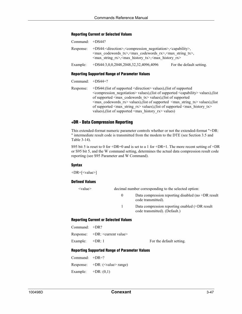
Commands Reference Manual
100498D Conexant 3-47
Reporting Current or Selected Values
Command: +DS44?
Response: +DS44:<direction>,<compression_negotiation>,<capability>,<max_codewords_tx>,<max_codewords_rx>,<max_string_tx>,<max_string_rx>,<max_history_tx>,<max_history_rx>
Example: +DS44:3,0,0,2048,2048,32,32,4096,4096 For the default setting.
Reporting Supported Range of Parameter Values
Command: +DS44=?
Response: +DS44:(list of supported <direction> values),(list of supported<compression_negotiation> values),(list of supported <capability> values),(listof supported <max_codewords_tx> values),(list of supported<max_codewords_rx> values),(list of supported <max_string_tx> values),(listof supported <max_string_rx> values),(list of supported <max_history_tx>values),(list of supported <max_history_rx> values)
+DR - Data Compression Reporting
This extended-format numeric parameter controls whether or not the extended-format "+DR:" intermediate result code is transmitted from the modem to the DTE (see Section 3.5 andTable 3-14).
S95 bit 5 is reset to 0 for +DR=0 and is set to a 1 for +DR=1. The more recent setting of +DRor S95 bit 5, and the W command setting, determines the actual data compression result codereporting (see S95 Parameter and W Command).
Syntax
+DR=[<value>]
Defined Values
<value> decimal number corresponding to the selected option:
0 Data compression reporting disabled (no +DR resultcode transmitted).
1 Data compression reporting enabled (+DR resultcode transmitted). (Default.)
Reporting Current or Selected Values
Command: +DR?
Response: +DR: <current value>
Example: +DR: 1 For the default setting.
Reporting Supported Range of Parameter Values
Command: +DR=?
Response: +DR: (<value> range)
Example: +DR: (0,1)

Commands Reference Manual
3-48 Conexant 100498D
+DR: <type> Intermediate Result Code
The +DR: <type> reported represents the current (negotiated or renegotiated) modem-modemdata compression type. If enabled, the intermediate result code is transmitted at the point aftererror control negotiation (handshaking) at which the modem has determined which datacompression technique will be used (if any) and the direction of operation. The +DRintermediate result code, if enabled, is issued after the Error Control Report (+ER) and beforethe final result code (e.g., CONNECT).
The format of this result code is:
Result Code Syntax
+DR: <type>
Defined Values
<type> An alphanumeric code corresponding to the selected option:
NONE Data compression is not in use.
V42B V.42bis is in use in both directions.
ALT MNP 5 compression.
Example
+DR: V42B
%C - Enable/Disable Data Compression
Enables or disables data compression negotiation. The modem can only perform datacompression on an error corrected link.
Syntax
%C[<value>]
Defined Values
<value> A decimal number corresponding to the selected option:
0 Disables data compression.
1 Enables both V.42 bis and MNP 5 data compression.
2 Enables both V.42 bis and MNP 5 data compression.
3 Enables both V.42 bis and MNP 5 data compression.(Default.)
Result Codes
OK <value> = 0, 1, 2, or 3.
ERROR Otherwise.
Commands Reference Manual
100498D Conexant 3-49
N - Automode Enable
This command is included for compatibility only and has no effect other than returning aresult code. The only valid values are 0-1.
Syntax
N[<mode>]
Defined Values
<mode > Decimal number corresponding to the selected value: 0-1.
Result Codes
OK <mode> = 0 to 1.
ERROR Otherwise.
3.2.7 V.8/V.8bis Commands
+A8E - V.8 and V.8bis Operation Controls
This command is defined for two conditions: as a parameter while the modem is on-hook,and as an action command while the modem is off-hook. If enabled, V.8 negotiation does notpreclude simultaneous implementation of other negotiation means (e.g., V.8bis, V.18, V.32bisAnnex A).
This command is a compound parameter if issued while the modem is on-hook, used toprecondition V.8 and V.8bis originating and answering operation. It is issued by the DTEbefore the Dial (D) or Answer (A) command, regardless of the state of the +FCLASSparameter.
This command is an action command if issued while the modem is off-hook, to (re)start V.8or V.8bis negotiation. For example, if initial V.8 negotiation failed, but subsequent T.30negotiation indicated V.8 capability, this command may be used to initiate V.8 negotiation.
Syntax
+A8E=<v8o>,<v8a>,<v8cf>[,<v8b>][,<cfrange>][,<protrange>]
Defined Values
<v8o> Decimal number which enables/disables issuance of +A8xindications during modem-controlled V.8 origination negotiation
1 Enable DCE-controlled V.8 origination negotiationwithout +A8x indications. (Default.)
6 Enable DCE-controlled V.8 origination negotiationwith +A8x indications.
<v8a>= Decimal number which enables/disables issuance of +A8xindications during modem-controlled V.8 answer negotiation.
1 Enable DCE-controlled V.8 answer negotiationwithout +A8x indications. (Default.)
5 Enable DCE-controlled V.8 answer negotiation with+A8x indications.
Commands Reference Manual
3-50 Conexant 100498D
<v8cf>= Set the V.8 CI signal call function to the hexadecimal octet valueX.
<v8b>= Decimal number which enables/disables V.8bis negotiation.
0 Disable V.8bis negotiation. (Default.)
1 Enable DCE-controlled V.8bis negotiation.
2 Enable DTE-controlled V.8bis negotiation.
<cfrange>= “<string of values>“. Applicable only for <v8a>=5 (notsupported).
< protrange >= “<string of values>“. Applicable only for <v8a>=5 (notsupported).
Default values: 1,1,,1,"",""
The ATD and ATA commands behave as specified in §6.3.1/V.25ter and §6.3.5/V.25ter,respectively, and +A8n indications are not generated by the modem.
For subparameter values <v8o>=6 and <v8a>=5, the +A8I, +A8C, +A8A, +A8J, and +A8Mindications are issued during the course of the V.8 session to notify the DTE when therelevant V.8 signals are received. The modem controls the V.8 session, however, and the+A8M command is not used.
Reporting Current or Selected Values
Command: +A8E?
Response: +A8E: <v8o>,<v8a>,<v8cf>[,<v8b>][,<cfrange>][,<protrange>]
Example: +A8E: 1,1,,1,"","" For the defaults
Reporting Supported Range of Parameter Values
Command: +A8E=?
Response: +A8E: (<v8o> range),(<v8a> range), (maximum size of v8cf in octets), (<v8b>range),(<cfrange> option bitrange),(<protrange> option bit range)
Example: +A8E: (1,6),(1,5),(1),(0),(1,6),(1)
+A8M - Send V.8 Menu Signals
This command, applicable only in DTE-controlled V.8, directs the modem to send a V.8 CMor JM signal using the specified hexadecimal coded string. If the modem can decode the menuoctet string, and if it cannot implement a specified feature, the modem reports an ERRORfinal result code, but stays in V.8 operation awaiting another command.
Syntax
+A8M=<hexadecimal coded CM or JM octet string>

Commands Reference Manual
100498D Conexant 3-51
+A8I: - CI Signal Indication
This indication is issued by an answering modem, if +A8E,<v8a> ≠ 0, to indicate detectionof a V.8 CI signal, and report the recovered Call Function octet(s).
Indication Syntax
+A8I:<v8cf><CR>
Defined Values
<v8cf> A hexadecimal code octet representation of those Call Functionoctet(s). +A8I:0 indicates that the modem timed out waiting for CI.
Example
+A8I:0 The modem timed out waiting for CI.
+A8I:X YYY
+A8C: - Calling Tone Indication
This indication is issued by an answering modem, if +A8E,<v8a> ≠ 0, to indicate detection of1100 Hz or 1300 Hz calling tones, or sigC signals, as defined in T.30, V.8 and in V.25.
Indication Syntax
+A8C: <type><CR>
Defined Values
<type> Decimal number which indicates the corresponding detectedcalling tone.
0 The modem concluded answer tone transmissionwithout reporting detection of any calling tone.
1 CNG tone (1100 Hz) detected.
2 1300 Hz V.25 data modem calling tone detected.
3 sigC signal: V.32/V.32bis AA tone detected.
Example
+A8C: 1 For CNG tone detected.

Commands Reference Manual
3-52 Conexant 100498D
+A8A: - Answer Signal Indication
This indication is issued by a calling modem, if +A8E <v8o> ≠ 0, to indicate detection of ananswering signal.
Indication Syntax
+A8A:<type><CR>
Defined Values
<type><CR> Decimal number which indicates the corresponding detectedanswer signal.
0 The modem timed out waiting for an answeringsignal.
1 V.8 ANSam signal (2100 Hz with amplitudemodulation) detected.
2 V.25 answer tone (2100 Hz) detected.
3 V.25 answer tone with phase reversals detected.(Note)
4 sigA signal: V.21 Ch2 with flags (e.g., T.30 controlpreamble) detected.
5 sigA signal: V.22bis USB1 signal detected.
6 sigA signal: V.32bis AC signal detected.
7 sigA signal: V.34 ToneA signal detected.
Example
+A8A:1 For V.8 ANSam signal (2100 Hz with amplitude modulation)detected.
+A8J: - V.8 Negotiation Complete
This indication is issued by either modem when the negotiation is complete and CJ is sent ordetected. An answering modem will issue this on detection of CJ from the remote terminal. Acalling modem will send a CJ signal to the remote terminal at the same time as a +A8Jindication. +A8J:1 indicates CJ; +A8J:0 indicates that the modem timed out waiting for a CJsignal.
Indication Syntax
+A8J:<value><CR>
Defined Values
<value> Decimal number corresponding to the selected option.
0 The modem timed out waiting for a CJ signal.
1 CJ signal sent or detected.
Example
+A8J:1 For CJ sent to a remote terminal.
Commands Reference Manual
100498D Conexant 3-53
+A8M: - V.8 Menu Report
This indication is issued by either modem, during V.8 negotiation, to indicate the contents ofa valid received CM or JM signal. A +A8M:0 indicates that the modem timed out waiting fora CM or JM signal.
Report Syntax
+A8M:< hex_string>
Defined Values
< hex_string> CM or JM hexadecimal coded string. A +A8M:0 indicates that themodem timed out waiting for a CM or JM signal.
Example
A8M:XXX YYY
+A8R: - V.8bis Signal and Message Reporting
If enabled by +A8E=,,,[<v8b>=2] command, the modem monitors for V.8bis signals andmessages, and uses the +A8R: intermediate result code response to report that signal. Twoconcatenated V.8bis messages are reported with two consecutive <message> indications.
Report Syntax
+A8R:<signal>[,[<1st message>]][,<2nd message>]<CR>
Defined Values
<signal> The V.8bis signal, if detected, is indicated using a <signal> value(see Table 3-3). Values of 4 and 8 are not reported, i.e., the modemis not expected to discern the power level of received CRe andMRd signals. If a V.8bis message is detected without a precedingV.8bis signal, the preamble is reported as a 0 <signal> value.
<1st message> The contents of valid V.8bis message(s), if detected, are reportedusing hexadecimal octet coded string(s) (A.4.1). Flag detection andconsumption, flag transparency 0-bit deletion and FCS checkingare performed by the modem. The modem does not report invalidmessages (e.g., bad FCS). If two consecutive messages aredetected but the first is invalid, the modem indicates this with nocharacters between the first and second comma (e.g.,+A8R:<signal>,,<2nd message>).
<2nd message See <1st message>.
Example
+A8R:0,XX,YY For a V.8bis message detected without a preceding V.8bis signal.
+A8R:0,XX,YY For a V.8bis message detected with a preceding V.8bis signal.
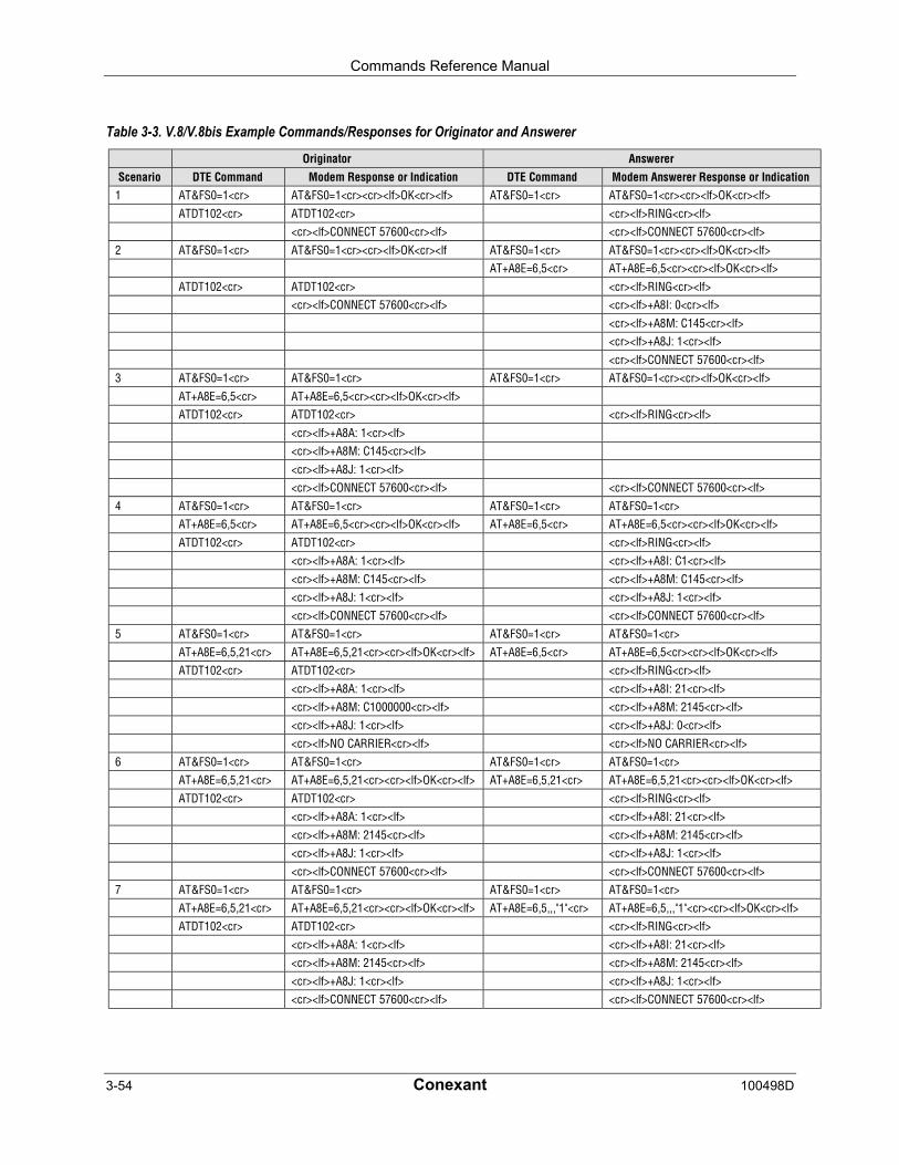
Commands Reference Manual
3-54 Conexant 100498D
Table 3-3. V.8/V.8bis Example Commands/Responses for Originator and Answerer
Originator Answerer
Scenario DTE Command Modem Response or Indication DTE Command Modem Answerer Response or Indication1 AT&FS0=1<cr> AT&FS0=1<cr><cr><lf>OK<cr><lf> AT&FS0=1<cr> AT&FS0=1<cr><cr><lf>OK<cr><lf>
ATDT102<cr> ATDT102<cr> <cr><lf>RING<cr><lf><cr><lf>CONNECT 57600<cr><lf> <cr><lf>CONNECT 57600<cr><lf>
2 AT&FS0=1<cr> AT&FS0=1<cr><cr><lf>OK<cr><lf AT&FS0=1<cr> AT&FS0=1<cr><cr><lf>OK<cr><lf>AT+A8E=6,5<cr> AT+A8E=6,5<cr><cr><lf>OK<cr><lf>
ATDT102<cr> ATDT102<cr> <cr><lf>RING<cr><lf><cr><lf>CONNECT 57600<cr><lf> <cr><lf>+A8I: 0<cr><lf>
<cr><lf>+A8M: C145<cr><lf><cr><lf>+A8J: 1<cr><lf>
<cr><lf>CONNECT 57600<cr><lf>3 AT&FS0=1<cr> AT&FS0=1<cr> AT&FS0=1<cr> AT&FS0=1<cr><cr><lf>OK<cr><lf>
AT+A8E=6,5<cr> AT+A8E=6,5<cr><cr><lf>OK<cr><lf>ATDT102<cr> ATDT102<cr> <cr><lf>RING<cr><lf>
<cr><lf>+A8A: 1<cr><lf><cr><lf>+A8M: C145<cr><lf>
<cr><lf>+A8J: 1<cr><lf><cr><lf>CONNECT 57600<cr><lf> <cr><lf>CONNECT 57600<cr><lf>
4 AT&FS0=1<cr> AT&FS0=1<cr> AT&FS0=1<cr> AT&FS0=1<cr>AT+A8E=6,5<cr> AT+A8E=6,5<cr><cr><lf>OK<cr><lf> AT+A8E=6,5<cr> AT+A8E=6,5<cr><cr><lf>OK<cr><lf>
ATDT102<cr> ATDT102<cr> <cr><lf>RING<cr><lf><cr><lf>+A8A: 1<cr><lf> <cr><lf>+A8I: C1<cr><lf>
<cr><lf>+A8M: C145<cr><lf> <cr><lf>+A8M: C145<cr><lf><cr><lf>+A8J: 1<cr><lf> <cr><lf>+A8J: 1<cr><lf>
<cr><lf>CONNECT 57600<cr><lf> <cr><lf>CONNECT 57600<cr><lf>5 AT&FS0=1<cr> AT&FS0=1<cr> AT&FS0=1<cr> AT&FS0=1<cr>
AT+A8E=6,5,21<cr> AT+A8E=6,5,21<cr><cr><lf>OK<cr><lf> AT+A8E=6,5<cr> AT+A8E=6,5<cr><cr><lf>OK<cr><lf>ATDT102<cr> ATDT102<cr> <cr><lf>RING<cr><lf>
<cr><lf>+A8A: 1<cr><lf> <cr><lf>+A8I: 21<cr><lf><cr><lf>+A8M: C1000000<cr><lf> <cr><lf>+A8M: 2145<cr><lf>
<cr><lf>+A8J: 1<cr><lf> <cr><lf>+A8J: 0<cr><lf><cr><lf>NO CARRIER<cr><lf> <cr><lf>NO CARRIER<cr><lf>
6 AT&FS0=1<cr> AT&FS0=1<cr> AT&FS0=1<cr> AT&FS0=1<cr>AT+A8E=6,5,21<cr> AT+A8E=6,5,21<cr><cr><lf>OK<cr><lf> AT+A8E=6,5,21<cr> AT+A8E=6,5,21<cr><cr><lf>OK<cr><lf>
ATDT102<cr> ATDT102<cr> <cr><lf>RING<cr><lf><cr><lf>+A8A: 1<cr><lf> <cr><lf>+A8I: 21<cr><lf>
<cr><lf>+A8M: 2145<cr><lf> <cr><lf>+A8M: 2145<cr><lf><cr><lf>+A8J: 1<cr><lf> <cr><lf>+A8J: 1<cr><lf>
<cr><lf>CONNECT 57600<cr><lf> <cr><lf>CONNECT 57600<cr><lf>7 AT&FS0=1<cr> AT&FS0=1<cr> AT&FS0=1<cr> AT&FS0=1<cr>
AT+A8E=6,5,21<cr> AT+A8E=6,5,21<cr><cr><lf>OK<cr><lf> AT+A8E=6,5,,,"1"<cr> AT+A8E=6,5,,,"1"<cr><cr><lf>OK<cr><lf>ATDT102<cr> ATDT102<cr> <cr><lf>RING<cr><lf>
<cr><lf>+A8A: 1<cr><lf> <cr><lf>+A8I: 21<cr><lf><cr><lf>+A8M: 2145<cr><lf> <cr><lf>+A8M: 2145<cr><lf>
<cr><lf>+A8J: 1<cr><lf> <cr><lf>+A8J: 1<cr><lf><cr><lf>CONNECT 57600<cr><lf> <cr><lf>CONNECT 57600<cr><lf>
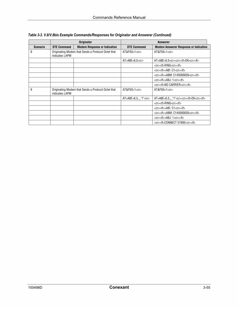
Commands Reference Manual
100498D Conexant 3-55
Table 3-3. V.8/V.8bis Example Commands/Responses for Originator and Answerer (Continued)
Originator Answerer
Scenario DTE Command Modem Response or Indication DTE Command Modem Answerer Response or Indication8 Originating Modem that Sends a Protocol Octet that
indicates LAPMAT&FS0=1<cr> AT&FS0=1<cr>
AT+A8E=6,5<cr> AT+A8E=6,5<cr><cr><lf>OK<cr><lf>
<cr><lf>RING<cr><lf><cr><lf>+A8I: C1<cr><lf>
<cr><lf>+A8M: C145000026<cr><lf><cr><lf>+A8J: 1<cr><lf>
<cr><lf>NO CARRIER<cr><lf>9 Originating Modem that Sends a Protocol Octet that
indicates LAPMAT&FS0=1<cr> AT&FS0=1<cr>
AT+A8E=6,5,,,,"1"<cr> AT+A8E=6,5,,,,"1"<cr><cr><lf>OK<cr><lf>
<cr><lf>RING<cr><lf><cr><lf>+A8I: C1<cr><lf>
<cr><lf>+A8M: C145000026<cr><lf><cr><lf>+A8J: 1<cr><lf>
<cr><lf>CONNECT 57600<cr><lf>

Commands Reference Manual
3-56 Conexant 100498D
3.2.8 Synchronous Access Mode Commands
+ESA - Configure Synchronous Access Mode
This extended-format compound parameter controls the manner of operation of theSynchronous Access Mode in the modem.
Enabling Synchronous Access Mode enables the use of the 8-bit command characters definedin Table 9/V.80 of the Draft ITU-T Recommendation V.80 (DATA COMMUNICATIONOVER THE TELEPHONE NETWORK; In-Band modem Control and Synchronous DataModes for Asynchronous DTE).
Syntax
+ESA=[<trans_idle>[,<framed_idle>[,<framed_un_ov>[,<hd_auto>[,<crc_type>[,<nrzi_en>[,<syn1>[,<syn2>]]]]]]]]
Defined Values
<trans_idle> Decimal number which specifies the bit sequence transmitted bythe modem when a transmit data buffer underrun condition occurs,while operating in Transparent sub-Mode. The options are:
0 In Transparent sub-Mode, modem transmits 8-bitSYN sequence on idle. Modem receiver does nothunt for synchronization sequence (default andfixed).
<framed_idle> Decimal number which specifies the bit sequence transmitted bythe modem when a transmit data buffer underrun condition occursimmediately after a flag, while operating in Framed sub-Mode.The options are:
0 In Framed sub-Mode, modem transmits HDLC flagson idle (default and fixed).
<framed_un_ov> Decimal number which specifies the actions undertaken by themodem when a transmit data buffer underrun or overrun conditionoccurs immediately after a non-flag octet, while operating inFramed sub-Mode.
0 In Framed sub-Mode, modem transmits abort onunderrun in middle of frame. (Default.)
1 In Framed sub-Mode, modem transmits a flag onunderrun in middle of frame, and notifies DTE ofunderrun or overrun.
<hd_auto> Decimal number which specifies whether or not, in V.34 half-duplex operation, additional procedures besides those specified in§ 12/V.34 will be performed by the modem when switching fromprimary channel to secondary channel operation, and vice versa.This subparameter should not be commanded.
<crc_type> Decimal number which specifies the CRC polynomial used whileoperating in Framed sub-Mode. The options are:
0 CRC generation and checking disabled. (Default andfixed.)
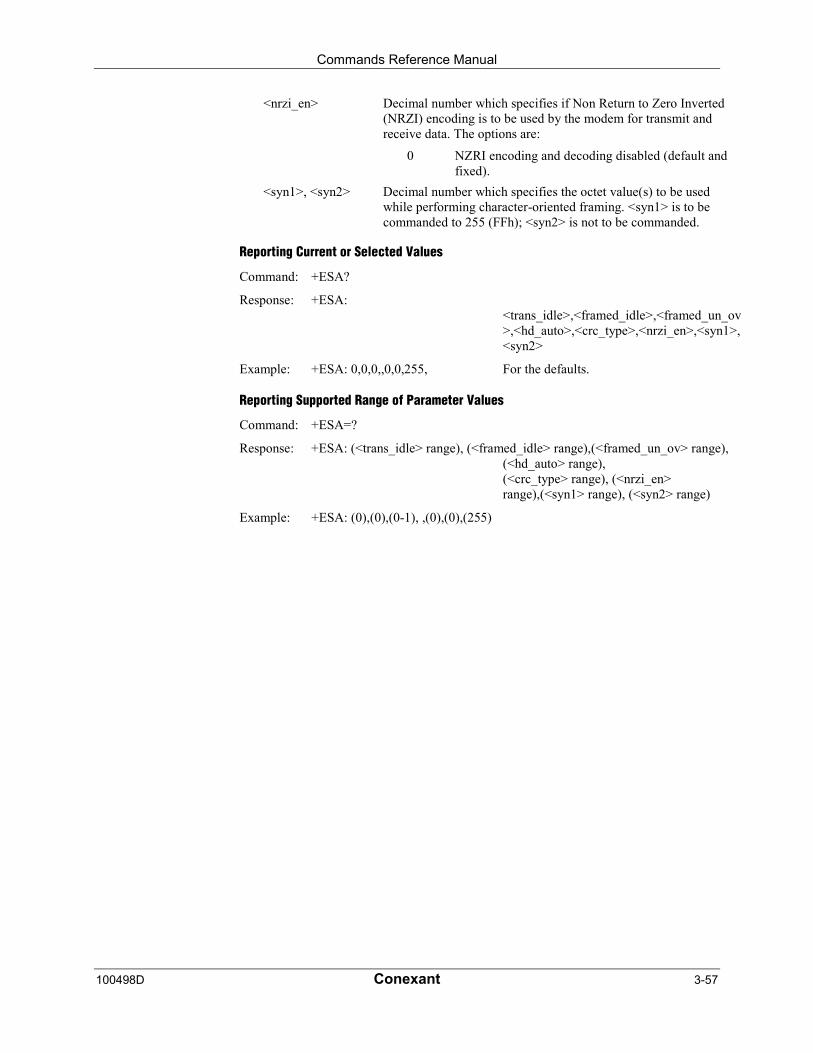
Commands Reference Manual
100498D Conexant 3-57
<nrzi_en> Decimal number which specifies if Non Return to Zero Inverted(NRZI) encoding is to be used by the modem for transmit andreceive data. The options are:
0 NZRI encoding and decoding disabled (default andfixed).
<syn1>, <syn2> Decimal number which specifies the octet value(s) to be usedwhile performing character-oriented framing. <syn1> is to becommanded to 255 (FFh); <syn2> is not to be commanded.
Reporting Current or Selected Values
Command: +ESA?
Response: +ESA:<trans_idle>,<framed_idle>,<framed_un_ov>,<hd_auto>,<crc_type>,<nrzi_en>,<syn1>,<syn2>
Example: +ESA: 0,0,0,,0,0,255, For the defaults.
Reporting Supported Range of Parameter Values
Command: +ESA=?
Response: +ESA: (<trans_idle> range), (<framed_idle> range),(<framed_un_ov> range),(<hd_auto> range),(<crc_type> range), (<nrzi_en>range),(<syn1> range), (<syn2> range)
Example: +ESA: (0),(0),(0-1), ,(0),(0),(255)

Commands Reference Manual
3-58 Conexant 100498D
+ITF - Transmit Flow Control Thresholds
In V.80 Synchronous Access Mode, this optional compound parameter allows the DTE todetermine the effective input buffer size in the modem for data on transmit data from theDTE, to control the thresholds used for flow control of such data, and to control how often themodem reports to the DTE the number of octets in this buffer. Note that the DTE can adjustits own thresholds for flow control of data on received data from the modem.
Syntax
+ITF=[<off>[,<on>[,<report_period>]]]
Defined Values
<off> Determines the threshold, in octets, above which the modem willgenerate a flow off signal. Applicable in Synchronous AccessMode.
The <off> range is 20 -7000. Default <off> value is 128.
For the <on> and <off> subparameters, the input buffer is assumedto reside between the modem’s V.24 interface and theSynchronous Access protocol layer; i.e., the buffer count includesall octets, including EM codes, received from the DTE, with theexception of XON and XOFF if these are used to signal <modem-by-DTE> flow control.
The modem returns the ERROR result code if the DTE specifiesthat the <off> subparameter be set to a value less than or equal tothe <on> subparameter; in this case, the current parameter valuesettings are set to default values.
<on> Determines the threshold, in octets, below which the modem willgenerate a flow on signal. Applicable in Synchronous AccessMode.
The <on> range is 10 -5000. Default <on> value is 64.
<report_period> Not supported. A fixed value of zero is used and reported.
Reporting Current or Selected Values
Command: +ITF?
Response: +ITF: <off>,<on>,<report_period>
Example: +ITF: 128,64,0 For default values
Reporting Supported Range of Parameter Values
Command: +ITF=?
Response: +ITF: (<off> range),(<on> range),(<report_period> range)
Example: +ITF: (20-7000),(10-5000),(0)

Commands Reference Manual
100498D Conexant 3-59
3.2.9 Diagnostic and Test Commands
#UD – Last Call Status Report
#UD is an action command requesting reporting of logged operation events. It does not takeparameters and must be the last command in the command line.
The modem logs aspects of their operation for each call, and saves these results until clearedby one of the following events:
1. Power off
2. Hard reset (e.g., negate DTR with &D3 set; reset button)
3. Soft reset = ATZ or AT&F
4. ATD command issued
5. ATA command issued
6. Automatic answer (e.g., set register S0>0 and ring detected)
These results are NOT cleared by changing DTR, V.24 circuit 108.2, if &D0, &D1 or &D2.
Data Call State Model
For purposes of this command, there are four data call states, and associated status issues:
• Call Setup
− Calling DCE: get dial tone, generate dial digits, detect call progress signals.
− Answering DCE: detect ringing, detect CallerID, etc.
• Negotiation
− V.25 calling tone/answer tone exchanges
− V.8 or V.8bis call function negotiations
− V-series modem carrier detection and training
− Modem-to-modem protocols (e.g., V.42, V.42bis).
• Data Transfer
− Bit-error rates, for each direction
− Rate renegotiation
− Retraining
• Call Termination
− protocol disconnect signals
− carrier disconnect signals
− loss of carrier
− excessive error rates
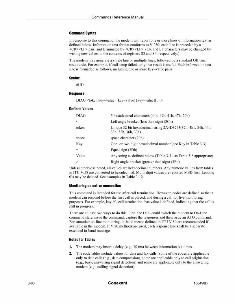
Commands Reference Manual
3-60 Conexant 100498D
Command Syntax
In response to this command, the modem will report one or more lines of information text asdefined below. Information text format conforms to V.250; each line is preceded by a<CR><LF> pair, and terminated by <CR><LF>. (CR and LF characters may be changed bywriting new values to the contents of registers S3 and S4, respectively.)
The modem may generate a single line or multiple lines, followed by a standard OK finalresult code. For example, if call setup failed, only that result is useful. Each information textline is formatted as follows, including one or more key=value pairs:
Syntax
#UD
Response
DIAG <token key=value [[key=value] [key=value]] …>
Defined Values
DIAG 5 hexadecimal characters (44h, 49h, 41h, 47h, 20h)
< Left angle bracket (less than sign) (3Ch)
token Unique 32-bit hexadecimal string 2A4D3263(32h, 4h1, 34h, 44h,33h, 32h, 36h, 33h)
space space character (20h)
Key One- or two-digit hexadecimal number (see Key in Table 3-3)
= Equal sign (3Dh)
Value Any string as defined below (Table 3-3 - as Table 3-8 appropriate)
> Right angle bracket (greater than sign) (3Eh)
Unless otherwise noted, all values are hexadecimal numbers. Any numeric values from tablesin ITU V.58 are converted to hexadecimal. Multi-digit values are reported MSD first. Leading0’s may be deleted. See examples in Table 3-12.
Monitoring an active connection
This command is intended for use after call termination. However, codes are defined so that amodem can respond before the first call is placed, and during a call for live monitoringpurposes. For example, key 60, call termination, has value 1 defined, indicating that the call isstill in progress.
There are at least two ways to do this. First, the DTE could switch the modem to On-Linecommand state, issue the command, capture the responses and then issue an ATO command.For smoother on-line monitoring, in-band means defined in ITU V.80 are recommended ifavailable in the modem. If V.80 methods are used, each response line shall be a separateextended in-band message.
Notes for Tables
1. The modem may insert a delay (e.g., 10 ms) between information text lines.
2. The code tables include values for data and fax calls. Some of the codes are applicableonly to data calls (e.g., data compression), some are applicable only to call origination(e.g., busy, answering signal detection) and some are applicable only to the answeringmodem (e.g., calling signal detection).
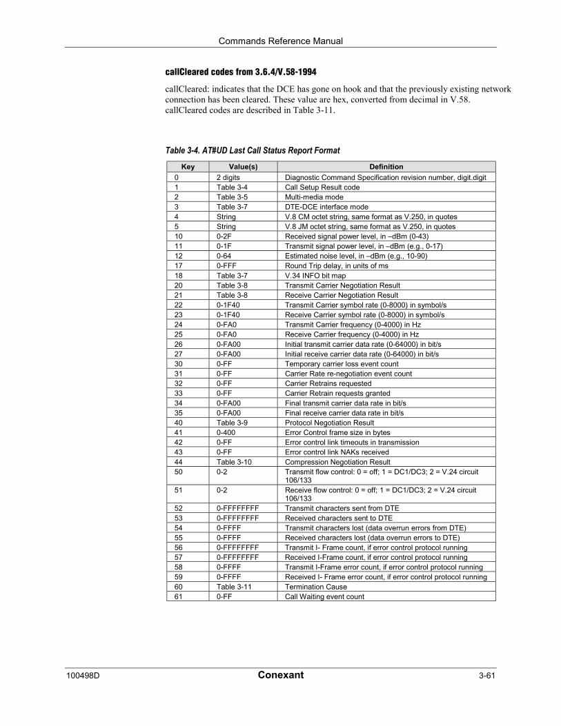
Commands Reference Manual
100498D Conexant 3-61
callCleared codes from 3.6.4/V.58-1994
callCleared: indicates that the DCE has gone on hook and that the previously existing networkconnection has been cleared. These value are hex, converted from decimal in V.58.callCleared codes are described in Table 3-11.
Table 3-4. AT#UD Last Call Status Report FormatKey Value(s) Definition
0 2 digits Diagnostic Command Specification revision number, digit.digit1 Table 3-4 Call Setup Result code2 Table 3-5 Multi-media mode3 Table 3-7 DTE-DCE interface mode4 String V.8 CM octet string, same format as V.250, in quotes5 String V.8 JM octet string, same format as V.250, in quotes10 0-2F Received signal power level, in –dBm (0-43)11 0-1F Transmit signal power level, in –dBm (e.g., 0-17)12 0-64 Estimated noise level, in –dBm (e.g., 10-90)17 0-FFF Round Trip delay, in units of ms18 Table 3-7 V.34 INFO bit map20 Table 3-8 Transmit Carrier Negotiation Result21 Table 3-8 Receive Carrier Negotiation Result22 0-1F40 Transmit Carrier symbol rate (0-8000) in symbol/s23 0-1F40 Receive Carrier symbol rate (0-8000) in symbol/s24 0-FA0 Transmit Carrier frequency (0-4000) in Hz25 0-FA0 Receive Carrier frequency (0-4000) in Hz26 0-FA00 Initial transmit carrier data rate (0-64000) in bit/s27 0-FA00 Initial receive carrier data rate (0-64000) in bit/s30 0-FF Temporary carrier loss event count31 0-FF Carrier Rate re-negotiation event count32 0-FF Carrier Retrains requested33 0-FF Carrier Retrain requests granted34 0-FA00 Final transmit carrier data rate in bit/s35 0-FA00 Final receive carrier data rate in bit/s40 Table 3-9 Protocol Negotiation Result41 0-400 Error Control frame size in bytes42 0-FF Error control link timeouts in transmission43 0-FF Error control link NAKs received44 Table 3-10 Compression Negotiation Result50 0-2 Transmit flow control: 0 = off; 1 = DC1/DC3; 2 = V.24 circuit
106/13351 0-2 Receive flow control: 0 = off; 1 = DC1/DC3; 2 = V.24 circuit
106/13352 0-FFFFFFFF Transmit characters sent from DTE53 0-FFFFFFFF Received characters sent to DTE54 0-FFFF Transmit characters lost (data overrun errors from DTE)55 0-FFFF Received characters lost (data overrun errors to DTE)56 0-FFFFFFFF Transmit I- Frame count, if error control protocol running57 0-FFFFFFFF Received I-Frame count, if error control protocol running58 0-FFFF Transmit I-Frame error count, if error control protocol running59 0-FFFF Received I- Frame error count, if error control protocol running60 Table 3-11 Termination Cause61 0-FF Call Waiting event count
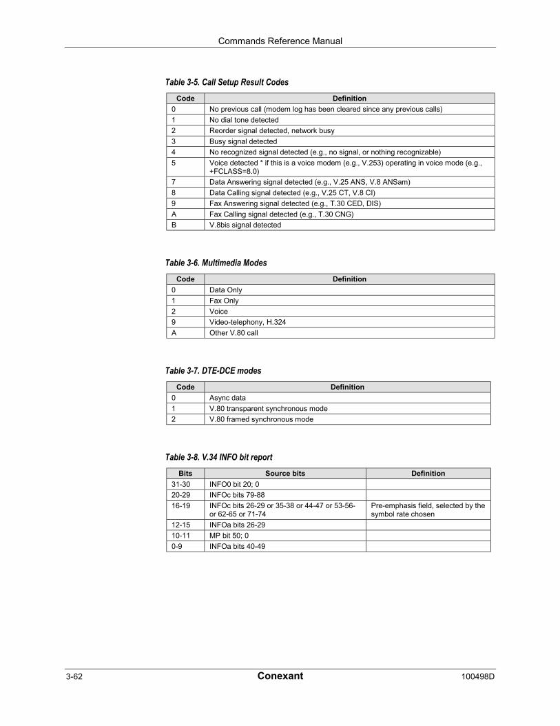
Commands Reference Manual
3-62 Conexant 100498D
Table 3-5. Call Setup Result CodesCode Definition
0 No previous call (modem log has been cleared since any previous calls)
1 No dial tone detected
2 Reorder signal detected, network busy
3 Busy signal detected
4 No recognized signal detected (e.g., no signal, or nothing recognizable)
5 Voice detected * if this is a voice modem (e.g., V.253) operating in voice mode (e.g.,+FCLASS=8.0)
7 Data Answering signal detected (e.g., V.25 ANS, V.8 ANSam)
8 Data Calling signal detected (e.g., V.25 CT, V.8 CI)
9 Fax Answering signal detected (e.g., T.30 CED, DIS)
A Fax Calling signal detected (e.g., T.30 CNG)
B V.8bis signal detected
Table 3-6. Multimedia ModesCode Definition
0 Data Only
1 Fax Only
2 Voice
9 Video-telephony, H.324
A Other V.80 call
Table 3-7. DTE-DCE modesCode Definition
0 Async data
1 V.80 transparent synchronous mode
2 V.80 framed synchronous mode
Table 3-8. V.34 INFO bit reportBits Source bits Definition
31-30 INFO0 bit 20; 0
20-29 INFOc bits 79-88
16-19 INFOc bits 26-29 or 35-38 or 44-47 or 53-56-or 62-65 or 71-74
Pre-emphasis field, selected by thesymbol rate chosen
12-15 INFOa bits 26-29
10-11 MP bit 50; 0
0-9 INFOa bits 40-49
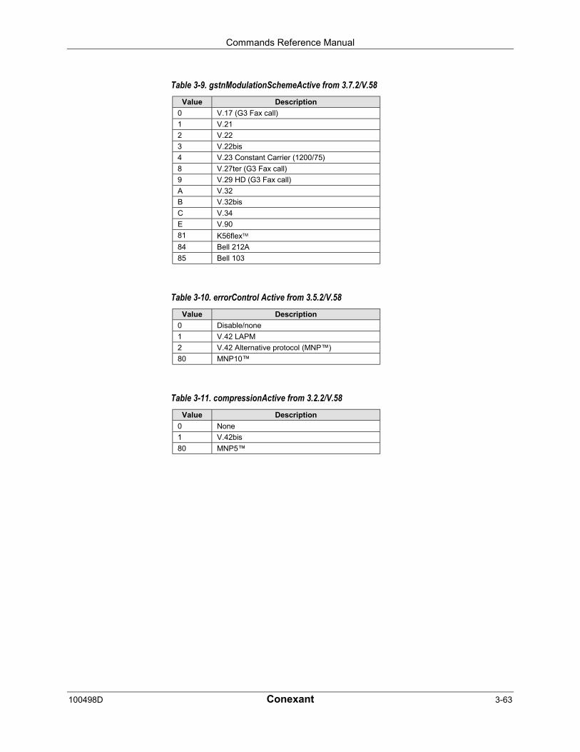
Commands Reference Manual
100498D Conexant 3-63
Table 3-9. gstnModulationSchemeActive from 3.7.2/V.58Value Description
0 V.17 (G3 Fax call)
1 V.21
2 V.22
3 V.22bis
4 V.23 Constant Carrier (1200/75)
8 V.27ter (G3 Fax call)
9 V.29 HD (G3 Fax call)
A V.32
B V.32bis
C V.34
E V.90
81 K56flex84 Bell 212A
85 Bell 103
Table 3-10. errorControl Active from 3.5.2/V.58Value Description
0 Disable/none
1 V.42 LAPM
2 V.42 Alternative protocol (MNP™)
80 MNP10™
Table 3-11. compressionActive from 3.2.2/V.58Value Description
0 None
1 V.42bis
80 MNP5™
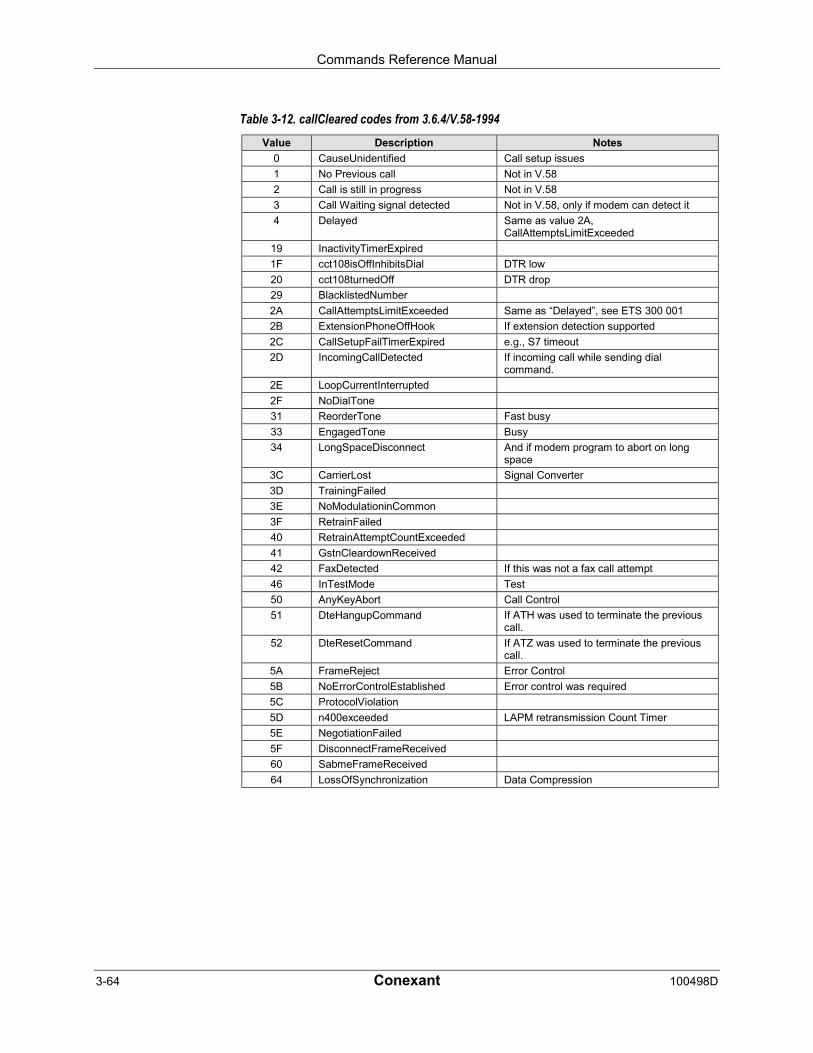
Commands Reference Manual
3-64 Conexant 100498D
Table 3-12. callCleared codes from 3.6.4/V.58-1994Value Description Notes
0 CauseUnidentified Call setup issues
1 No Previous call Not in V.58
2 Call is still in progress Not in V.58
3 Call Waiting signal detected Not in V.58, only if modem can detect it
4 Delayed Same as value 2A,CallAttemptsLimitExceeded
19 InactivityTimerExpired
1F cct108isOffInhibitsDial DTR low
20 cct108turnedOff DTR drop
29 BlacklistedNumber
2A CallAttemptsLimitExceeded Same as “Delayed”, see ETS 300 001
2B ExtensionPhoneOffHook If extension detection supported
2C CallSetupFailTimerExpired e.g., S7 timeout
2D IncomingCallDetected If incoming call while sending dialcommand.
2E LoopCurrentInterrupted
2F NoDialTone
31 ReorderTone Fast busy
33 EngagedTone Busy
34 LongSpaceDisconnect And if modem program to abort on longspace
3C CarrierLost Signal Converter
3D TrainingFailed
3E NoModulationinCommon
3F RetrainFailed
40 RetrainAttemptCountExceeded
41 GstnCleardownReceived
42 FaxDetected If this was not a fax call attempt
46 InTestMode Test
50 AnyKeyAbort Call Control
51 DteHangupCommand If ATH was used to terminate the previouscall.
52 DteResetCommand If ATZ was used to terminate the previouscall.
5A FrameReject Error Control
5B NoErrorControlEstablished Error control was required
5C ProtocolViolation
5D n400exceeded LAPM retransmission Count Timer
5E NegotiationFailed
5F DisconnectFrameReceived
60 SabmeFrameReceived
64 LossOfSynchronization Data Compression
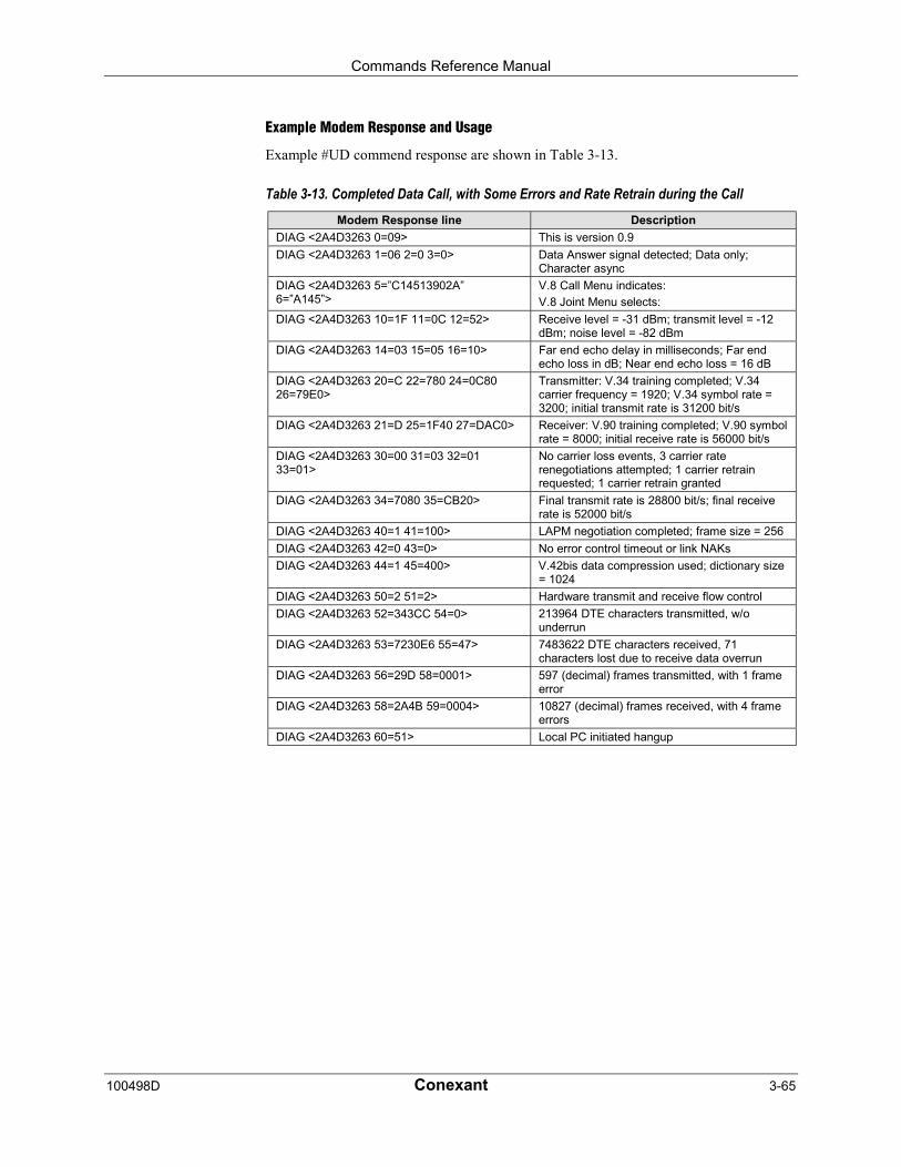
Commands Reference Manual
100498D Conexant 3-65
Example Modem Response and Usage
Example #UD commend response are shown in Table 3-13.
Table 3-13. Completed Data Call, with Some Errors and Rate Retrain during the CallModem Response line Description
DIAG <2A4D3263 0=09> This is version 0.9
DIAG <2A4D3263 1=06 2=0 3=0> Data Answer signal detected; Data only;Character async
DIAG <2A4D3263 5=”C14513902A”6=”A145”>
V.8 Call Menu indicates:
V.8 Joint Menu selects:
DIAG <2A4D3263 10=1F 11=0C 12=52> Receive level = -31 dBm; transmit level = -12dBm; noise level = -82 dBm
DIAG <2A4D3263 14=03 15=05 16=10> Far end echo delay in milliseconds; Far endecho loss in dB; Near end echo loss = 16 dB
DIAG <2A4D3263 20=C 22=780 24=0C8026=79E0>
Transmitter: V.34 training completed; V.34carrier frequency = 1920; V.34 symbol rate =3200; initial transmit rate is 31200 bit/s
DIAG <2A4D3263 21=D 25=1F40 27=DAC0> Receiver: V.90 training completed; V.90 symbolrate = 8000; initial receive rate is 56000 bit/s
DIAG <2A4D3263 30=00 31=03 32=0133=01>
No carrier loss events, 3 carrier raterenegotiations attempted; 1 carrier retrainrequested; 1 carrier retrain granted
DIAG <2A4D3263 34=7080 35=CB20> Final transmit rate is 28800 bit/s; final receiverate is 52000 bit/s
DIAG <2A4D3263 40=1 41=100> LAPM negotiation completed; frame size = 256
DIAG <2A4D3263 42=0 43=0> No error control timeout or link NAKs
DIAG <2A4D3263 44=1 45=400> V.42bis data compression used; dictionary size= 1024
DIAG <2A4D3263 50=2 51=2> Hardware transmit and receive flow control
DIAG <2A4D3263 52=343CC 54=0> 213964 DTE characters transmitted, w/ounderrun
DIAG <2A4D3263 53=7230E6 55=47> 7483622 DTE characters received, 71characters lost due to receive data overrun
DIAG <2A4D3263 56=29D 58=0001> 597 (decimal) frames transmitted, with 1 frameerror
DIAG <2A4D3263 58=2A4B 59=0004> 10827 (decimal) frames received, with 4 frameerrors
DIAG <2A4D3263 60=51> Local PC initiated hangup

Commands Reference Manual
3-66 Conexant 100498D
%TT - PTT Test Command
This command facilitates PTT testing of signal levels by providing continuous signals regardsof whether or not the modem is connected to the line. The signal transmitted is in accordancewith the parameter provided.
A range of commands allows the user to initiate a series of signals required to obtain PTTapproval. The signals emitted include answer tone, modulation, carriers, and other pertinentsignals. A test is initiated upon receipt of a %TTn (the second T is a password and n is a testnumber), and the test is aborted when any keyboard character is entered. The modem willcontinuously transmit the tone or carrier according to the parameter supplied.
Syntax
%TT0x x corresponds to the desired DTMF dial digit (0, 1, 2, 3, 4, 5, 6, 7,8, 9, *, #, A, B, C, or D).
0 Dial digit 0
1 Dial digit 1
2 Dial digit 2
3 Dial digit 3
4 Dial digit 4
5 Dial digit 5
6 Dial digit 6
7 Dial digit 7
8 Dial digit 8
9 Dial digit 9
A Dial digit *
B Dial digit #
C Dial digit A
D Dial digit B
E Dial digit C
F Dial digit D
%TT1x x corresponds to the desired FSK mode (V21Ch1, V21Ch2,V23Ch1, V23Ch2, Bell103Ch1, or Bell103Ch2).
0 V21Ch1
1 V21Ch2
2 V23Ch1
3 V23Ch2
4 Bell103Ch1
5 Bell103Ch2
6-F Reserved
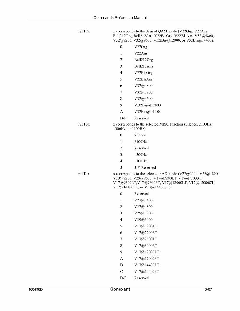
Commands Reference Manual
100498D Conexant 3-67
%TT2x x corresponds to the desired QAM mode (V22Org, V22Ans,Bell212Org, Bell212Ans, V22BisOrg, V22BisAns, V32@4800,V32@7200, V32@9600, V.32Bis@12000, or V32Bis@14400).
0 V22Org
1 V22Ans
2 Bell212Org
3 Bell212Ans
4 V22BisOrg
5 V22BisAns
6 V32@4800
7 V32@7200
8 V32@9600
9 V.32Bis@12000
A V32Bis@14400
B-F Reserved
%TT3x x corresponds to the selected MISC function (Silence, 2100Hz,1300Hz, or 1100Hz).
0 Silence
1 2100Hz
2 Reserved
3 1300Hz
4 1100Hz
5 5-F Reserved
%TT4x x corresponds to the selected FAX mode (V27@2400, V27@4800,V29@7200, V29@9600, V17@7200LT, V17@7200ST,V17@9600LT,V17@9600ST, V17@12000LT, V17@12000ST,V17@14400LT, or V17@14400ST).
0 Reserved
1 V27@2400
2 V27@4800
3 V29@7200
4 V29@9600
5 V17@7200LT
6 V17@7200ST
7 V17@9600LT
8 V17@9600ST
9 V17@12000LT
A V17@12000ST
B V17@14400LT
C V17@14400ST
D-F Reserved
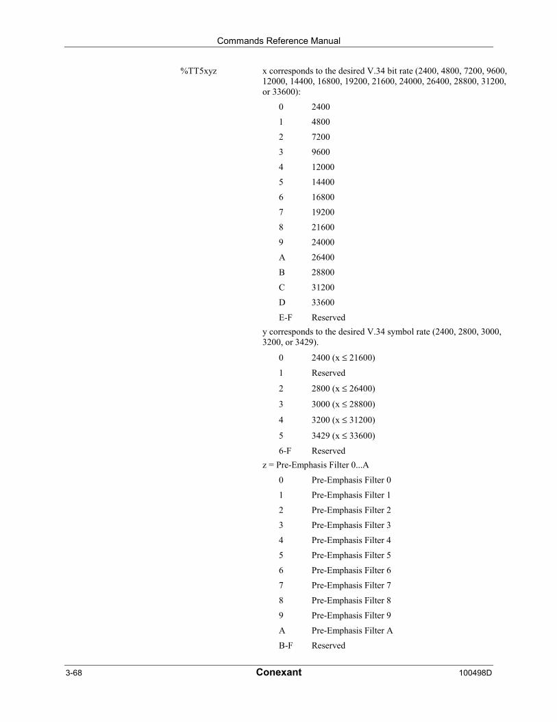
Commands Reference Manual
3-68 Conexant 100498D
%TT5xyz x corresponds to the desired V.34 bit rate (2400, 4800, 7200, 9600,12000, 14400, 16800, 19200, 21600, 24000, 26400, 28800, 31200,or 33600):
0 2400
1 4800
2 7200
3 9600
4 12000
5 14400
6 16800
7 19200
8 21600
9 24000
A 26400
B 28800
C 31200
D 33600
E-F Reserved
y corresponds to the desired V.34 symbol rate (2400, 2800, 3000,3200, or 3429).
0 2400 (x ≤ 21600)
1 Reserved
2 2800 (x ≤ 26400)
3 3000 (x ≤ 28800)
4 3200 (x ≤ 31200)
5 3429 (x ≤ 33600)
6-F Reserved
z = Pre-Emphasis Filter 0...A
0 Pre-Emphasis Filter 0
1 Pre-Emphasis Filter 1
2 Pre-Emphasis Filter 2
3 Pre-Emphasis Filter 3
4 Pre-Emphasis Filter 4
5 Pre-Emphasis Filter 5
6 Pre-Emphasis Filter 6
7 Pre-Emphasis Filter 7
8 Pre-Emphasis Filter 8
9 Pre-Emphasis Filter 9
A Pre-Emphasis Filter A
B-F Reserved
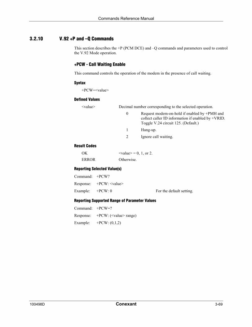
Commands Reference Manual
100498D Conexant 3-69
3.2.10 V.92 +P and –Q Commands
This section describes the +P (PCM DCE) and –Q commands and parameters used to controlthe V.92 Mode operation.
+PCW - Call Waiting Enable
This command controls the operation of the modem in the presence of call waiting.
Syntax
+PCW=<value>
Defined Values
<value> Decimal number corresponding to the selected operation.
0 Request modem-on-hold if enabled by +PMH andcollect caller ID information if enabled by +VRID.Toggle V.24 circuit 125. (Default.)
1 Hang-up.
2 Ignore call waiting.
Result Codes
OK <value> = 0, 1, or 2.
ERROR Otherwise.
Reporting Selected Value(s)
Command: +PCW?
Response: +PCW: <value>
Example: +PCW: 0 For the default setting.
Reporting Supported Range of Parameter Values
Command: +PCW=?
Response: +PCW: (<value> range)
Example: +PCW: (0,1,2)
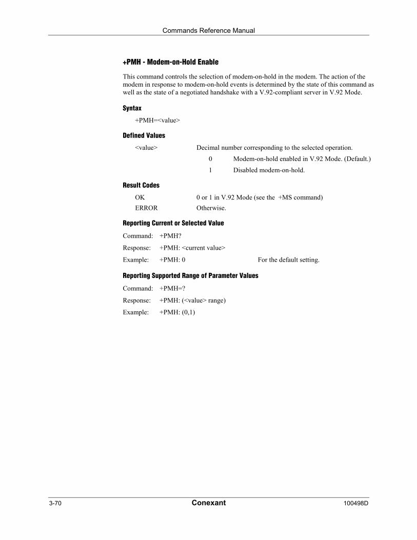
Commands Reference Manual
3-70 Conexant 100498D
+PMH - Modem-on-Hold Enable
This command controls the selection of modem-on-hold in the modem. The action of themodem in response to modem-on-hold events is determined by the state of this command aswell as the state of a negotiated handshake with a V.92-compliant server in V.92 Mode.
Syntax
+PMH=<value>
Defined Values
<value> Decimal number corresponding to the selected operation.
0 Modem-on-hold enabled in V.92 Mode. (Default.)
1 Disabled modem-on-hold.
Result Codes
OK 0 or 1 in V.92 Mode (see the +MS command)
ERROR Otherwise.
Reporting Current or Selected Value
Command: +PMH?
Response: +PMH: <current value>
Example: +PMH: 0 For the default setting.
Reporting Supported Range of Parameter Values
Command: +PMH=?
Response: +PMH: (<value> range)
Example: +PMH: (0,1)
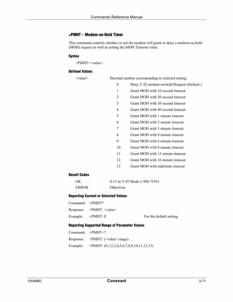
Commands Reference Manual
100498D Conexant 3-71
+PMHT – Modem-on-Hold Timer
This command controls whether or not the modem will grant or deny a modem-on-hold(MOH) request as well as setting the MOH Timeout value.
Syntax
+PMHT=<value>
Defined Values
<value> Decimal number corresponding to selected setting.
0 Deny V.92 modem-on-hold Request (Default.)
1 Grant MOH with 10 second timeout
2 Grant MOH with 20 second timeout
3 Grant MOH with 30 second timeout
4 Grant MOH with 40 second timeout
5 Grant MOH with 1 minute timeout
6 Grant MOH with 2 minute timeout
7 Grant MOH with 3 minute timeout
8 Grant MOH with 4 minute timeout
9 Grant MOH with 6 minute timeout
10 Grant MOH with 8 minute timeout
11 Grant MOH with 12 minute timeout
12 Grant MOH with 16 minute timeout
13 Grant MOH with indefinite timeout
Result Codes
OK 0-13 in V.92 Mode (+MS=V92)
ERROR Otherwise
Reporting Current or Selected Values
Command: +PMHT?
Response: +PMHT: <value>
Example: +PMHT: 0 For the default setting.
Reporting Supported Range of Parameter Values
Command: +PMHT=?
Response: +PMHT: (<value> range)
Example: +PMHT: (0,1,2,3,4,5,6,7,8,9,10,11,12,13)
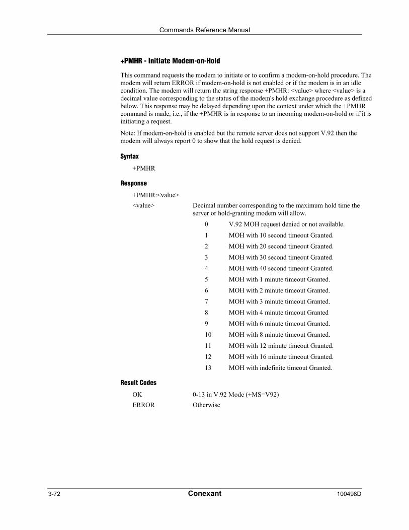
Commands Reference Manual
3-72 Conexant 100498D
+PMHR - Initiate Modem-on-Hold
This command requests the modem to initiate or to confirm a modem-on-hold procedure. Themodem will return ERROR if modem-on-hold is not enabled or if the modem is in an idlecondition. The modem will return the string response +PMHR: <value> where <value> is adecimal value corresponding to the status of the modem's hold exchange procedure as definedbelow. This response may be delayed depending upon the context under which the +PMHRcommand is made, i.e., if the +PMHR is in response to an incoming modem-on-hold or if it isinitiating a request.
Note: If modem-on-hold is enabled but the remote server does not support V.92 then themodem will always report 0 to show that the hold request is denied.
Syntax
+PMHR
Response
+PMHR:<value>
<value> Decimal number corresponding to the maximum hold time theserver or hold-granting modem will allow.
0 V.92 MOH request denied or not available.
1 MOH with 10 second timeout Granted.
2 MOH with 20 second timeout Granted.
3 MOH with 30 second timeout Granted.
4 MOH with 40 second timeout Granted.
5 MOH with 1 minute timeout Granted.
6 MOH with 2 minute timeout Granted.
7 MOH with 3 minute timeout Granted.
8 MOH with 4 minute timeout Granted
9 MOH with 6 minute timeout Granted.
10 MOH with 8 minute timeout Granted.
11 MOH with 12 minute timeout Granted.
12 MOH with 16 minute timeout Granted.
13 MOH with indefinite timeout Granted.
Result Codes
OK 0-13 in V.92 Mode (+MS=V92)
ERROR Otherwise
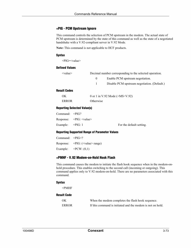
Commands Reference Manual
100498D Conexant 3-73
+PIG - PCM Upstream Ignore
This command controls the selection of PCM upstream in the modem. The actual state ofPCM upstream is determined by the state of this command as well as the state of a negotiatedhandshake with a V.92-compliant server in V.92 Mode.
Note: This command is not applicable to HCF products.
Syntax
+PIG=<value>
Defined Values
<value> Decimal number corresponding to the selected operation.
0 Enable PCM upstream negotiation.
1 Disable PCM upstream negotiation. (Default.)
Result Codes
OK 0 or 1 in V.92 Mode (+MS=V.92)
ERROR Otherwise
Reporting Selected Value(s)
Command: +PIG?
Response: +PIG: <value>
Example: +PIG: 1 For the default setting.
Reporting Supported Range of Parameter Values
Command: +PIG=?
Response: +PIG: (<value> range)
Example: +PCW: (0,1)
+PMHF - V.92 Modem-on-Hold Hook Flash
This command causes the modem to initiate the flash hook sequence when in the modem-on-hold procedure. This enables switching to the second call (incoming or outgoing). Thiscommand applies only to V.92 modem-on-hold. There are no parameters associated with thiscommand.
Syntax
+PMHF
Result Code
OK When the modem completes the flash hook sequence.
ERROR If this command is initiated and the modem is not on hold.
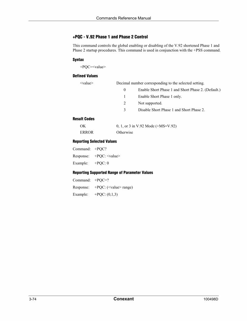
Commands Reference Manual
3-74 Conexant 100498D
+PQC - V.92 Phase 1 and Phase 2 Control
This command controls the global enabling or disabling of the V.92 shortened Phase 1 andPhase 2 startup procedures. This command is used in conjunction with the +PSS command.
Syntax
+PQC=<value>
Defined Values
<value> Decimal number corresponding to the selected setting.
0 Enable Short Phase 1 and Short Phase 2. (Default.)
1 Enable Short Phase 1 only.
2 Not supported.
3 Disable Short Phase 1 and Short Phase 2.
Result Codes
OK 0, 1, or 3 in V.92 Mode (+MS=V.92)
ERROR Otherwise
Reporting Selected Values
Command: +PQC?
Response: +PQC: <value>
Example: +PQC: 0
Reporting Supported Range of Parameter Values
Command: +PQC=?
Response: +PQC: (<value> range)
Example: +PQC: (0,1,3)
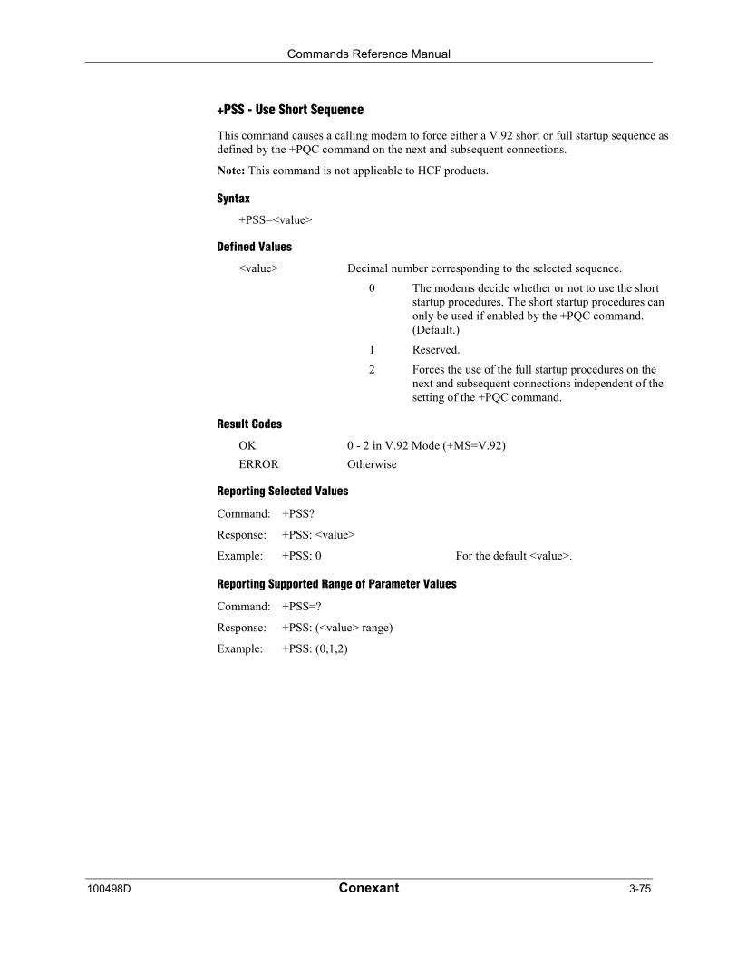
Commands Reference Manual
100498D Conexant 3-75
+PSS - Use Short Sequence
This command causes a calling modem to force either a V.92 short or full startup sequence asdefined by the +PQC command on the next and subsequent connections.
Note: This command is not applicable to HCF products.
Syntax
+PSS=<value>
Defined Values
<value> Decimal number corresponding to the selected sequence.
0 The modems decide whether or not to use the shortstartup procedures. The short startup procedures canonly be used if enabled by the +PQC command.(Default.)
1 Reserved.
2 Forces the use of the full startup procedures on thenext and subsequent connections independent of thesetting of the +PQC command.
Result Codes
OK 0 - 2 in V.92 Mode (+MS=V.92)
ERROR Otherwise
Reporting Selected Values
Command: +PSS?
Response: +PSS: <value>
Example: +PSS: 0 For the default <value>.
Reporting Supported Range of Parameter Values
Command: +PSS=?
Response: +PSS: (<value> range)
Example: +PSS: (0,1,2)
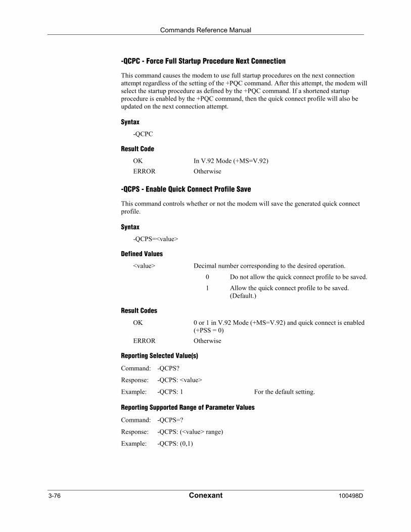
Commands Reference Manual
3-76 Conexant 100498D
-QCPC - Force Full Startup Procedure Next Connection
This command causes the modem to use full startup procedures on the next connectionattempt regardless of the setting of the +PQC command. After this attempt, the modem willselect the startup procedure as defined by the +PQC command. If a shortened startupprocedure is enabled by the +PQC command, then the quick connect profile will also beupdated on the next connection attempt.
Syntax
-QCPC
Result Code
OK In V.92 Mode (+MS=V.92)
ERROR Otherwise
-QCPS - Enable Quick Connect Profile Save
This command controls whether or not the modem will save the generated quick connectprofile.
Syntax
-QCPS=<value>
Defined Values
<value> Decimal number corresponding to the desired operation.
0 Do not allow the quick connect profile to be saved.
1 Allow the quick connect profile to be saved.(Default.)
Result Codes
OK 0 or 1 in V.92 Mode (+MS=V.92) and quick connect is enabled(+PSS = 0)
ERROR Otherwise
Reporting Selected Value(s)
Command: -QCPS?
Response: -QCPS: <value>
Example: -QCPS: 1 For the default setting.
Reporting Supported Range of Parameter Values
Command: -QCPS=?
Response: -QCPS: (<value> range)
Example: -QCPS: (0,1)
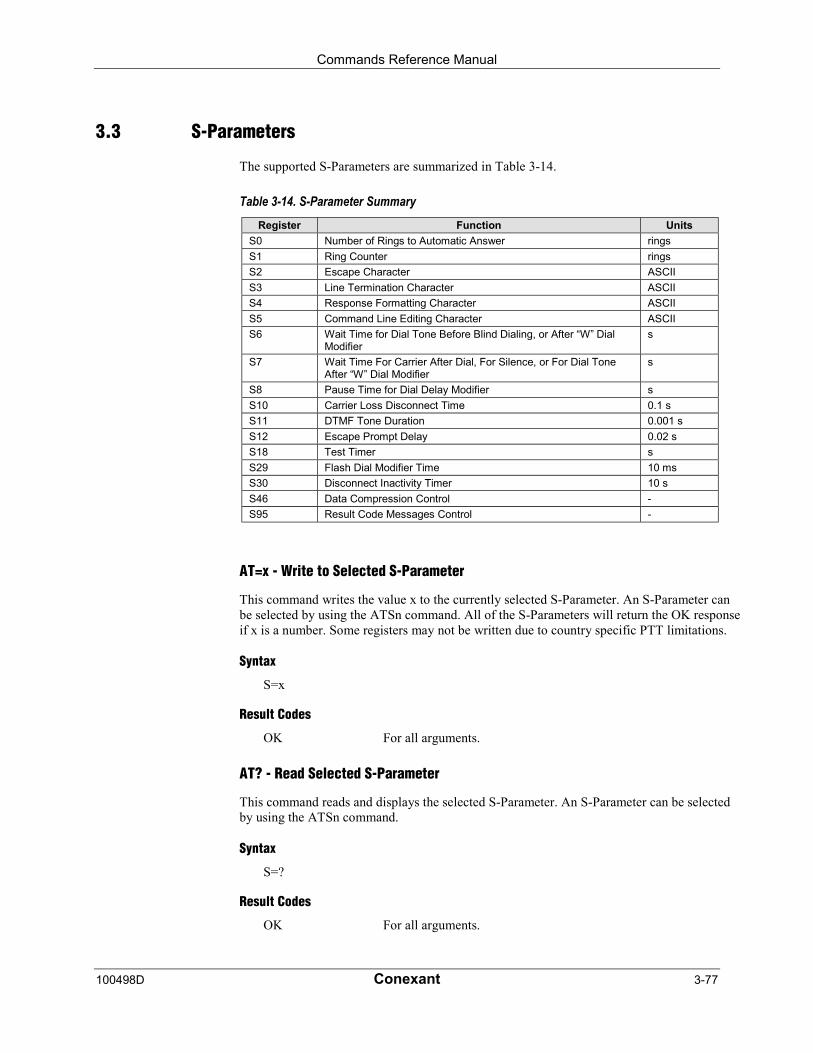
Commands Reference Manual
100498D Conexant 3-77
3.3 S-Parameters
The supported S-Parameters are summarized in Table 3-14.
Table 3-14. S-Parameter SummaryRegister Function Units
S0 Number of Rings to Automatic Answer rings
S1 Ring Counter rings
S2 Escape Character ASCII
S3 Line Termination Character ASCII
S4 Response Formatting Character ASCII
S5 Command Line Editing Character ASCII
S6 Wait Time for Dial Tone Before Blind Dialing, or After “W” DialModifier
s
S7 Wait Time For Carrier After Dial, For Silence, or For Dial ToneAfter “W” Dial Modifier
s
S8 Pause Time for Dial Delay Modifier s
S10 Carrier Loss Disconnect Time 0.1 s
S11 DTMF Tone Duration 0.001 s
S12 Escape Prompt Delay 0.02 s
S18 Test Timer s
S29 Flash Dial Modifier Time 10 ms
S30 Disconnect Inactivity Timer 10 s
S46 Data Compression Control -
S95 Result Code Messages Control -
AT=x - Write to Selected S-Parameter
This command writes the value x to the currently selected S-Parameter. An S-Parameter canbe selected by using the ATSn command. All of the S-Parameters will return the OK responseif x is a number. Some registers may not be written due to country specific PTT limitations.
Syntax
S=x
Result Codes
OK For all arguments.
AT? - Read Selected S-Parameter
This command reads and displays the selected S-Parameter. An S-Parameter can be selectedby using the ATSn command.
Syntax
S=?
Result Codes
OK For all arguments.
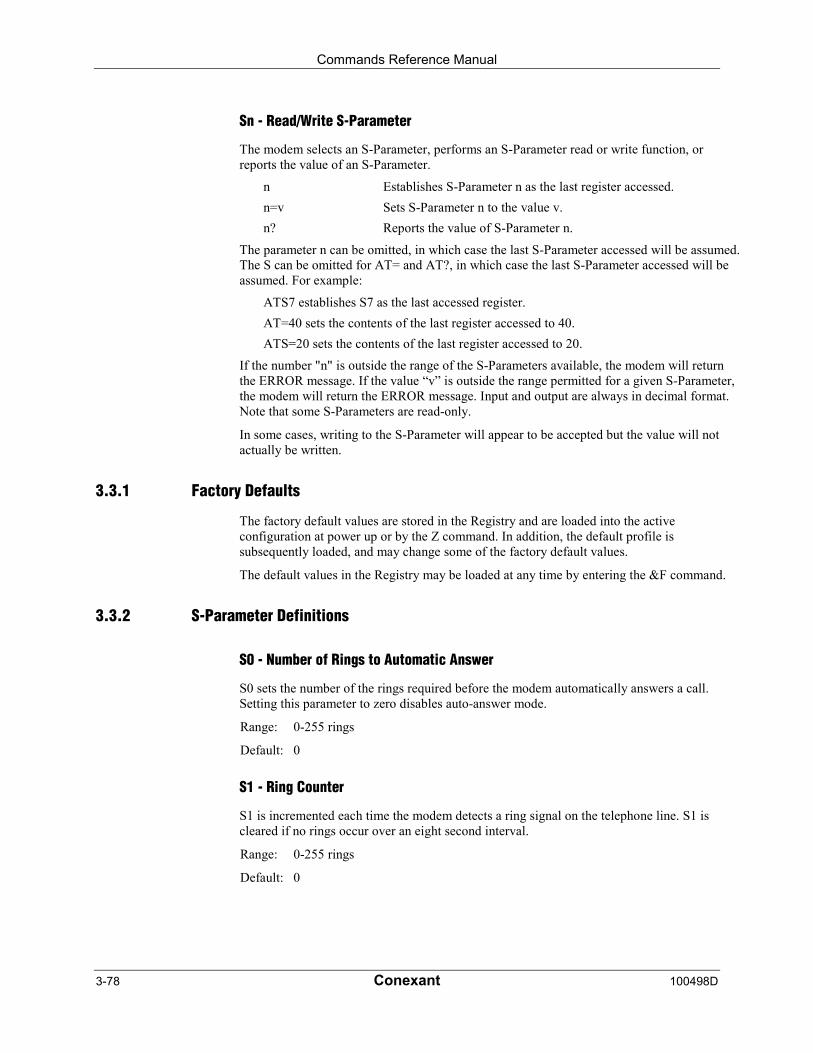
Commands Reference Manual
3-78 Conexant 100498D
Sn - Read/Write S-Parameter
The modem selects an S-Parameter, performs an S-Parameter read or write function, orreports the value of an S-Parameter.
n Establishes S-Parameter n as the last register accessed.
n=v Sets S-Parameter n to the value v.
n? Reports the value of S-Parameter n.
The parameter n can be omitted, in which case the last S-Parameter accessed will be assumed.The S can be omitted for AT= and AT?, in which case the last S-Parameter accessed will beassumed. For example:
ATS7 establishes S7 as the last accessed register.
AT=40 sets the contents of the last register accessed to 40.
ATS=20 sets the contents of the last register accessed to 20.
If the number "n" is outside the range of the S-Parameters available, the modem will returnthe ERROR message. If the value “v” is outside the range permitted for a given S-Parameter,the modem will return the ERROR message. Input and output are always in decimal format.Note that some S-Parameters are read-only.
In some cases, writing to the S-Parameter will appear to be accepted but the value will notactually be written.
3.3.1 Factory Defaults
The factory default values are stored in the Registry and are loaded into the activeconfiguration at power up or by the Z command. In addition, the default profile issubsequently loaded, and may change some of the factory default values.
The default values in the Registry may be loaded at any time by entering the &F command.
3.3.2 S-Parameter Definitions
S0 - Number of Rings to Automatic Answer
S0 sets the number of the rings required before the modem automatically answers a call.Setting this parameter to zero disables auto-answer mode.
Range: 0-255 rings
Default: 0
S1 - Ring Counter
S1 is incremented each time the modem detects a ring signal on the telephone line. S1 iscleared if no rings occur over an eight second interval.
Range: 0-255 rings
Default: 0
Commands Reference Manual
100498D Conexant 3-79
S2 - Escape Character
S2 holds the decimal value of the ASCII character used as the escape character. The defaultvalue corresponds to an ASCII '+'. A value over 127 disables the escape process, i.e., noescape character will be recognized.
Range: 0-255, ASCII decimal
Default: 43 (+)
S3 - Line Termination Character
S3 sets the decimal value of the command line and result code terminator character. Pertainsto asynchronous operation only.
Range: 0-127, ASCII decimal
Default: 13 (Carriage Return)
S4 - Response Formatting Character
S4 sets the decimal value of the character generated by the modem as part of the header,trailer, and terminator for result codes and information text, along with the S3 parameter (seethe description of the V parameter for usage). If the value of S4 is changed in a commandline, the result code issued in response to that command line will use the new value of S4.
The Response Formatting character is output after the Line Termination character if verboseresult codes are used.
Range: 0-127, ASCII decimal
Default: 10 (Line Feed)
S5 - Command Line Editing Character
S5 s sets the decimal value of the character recognized by the modem as a request to deletefrom the command line the immediately preceding character. The modem will not recognizethe Command Line Editing character if it is set to a value that is greater than 32 ASCII. Thischaracter can be used to edit a command line. When the echo command is enabled, themodem echoes back to the local DTE the Command Line Editing character, an ASCII spacecharacter and a second Command Line Editing character; this means a total of threecharacters are transmitted each time the modem processes the Command Line Editingcharacter.
Range: 0-32, ASCII decimal
Default: 8 (Backspace)
Commands Reference Manual
3-80 Conexant 100498D
S6 - Wait Time for Dial Tone Before Blind Dialing, or After “W” Dial Modifier
S6 sets one of two possible parameters:
1. Sets the length of time, in seconds, that the modem will wait before starting to dial aftergoing off-hook when blind dialing.
2. If enabled by country options in the INF file, S6 sets the length of time, in seconds, thatthe modem will wait for dial tone when encountering a “W” dial modifier beforereturning NO DIAL TONE result code.
The modem always pauses for a minimum of 2 seconds, even if the value of S6 is less than 2seconds.
Range: 2-255 seconds
Default: 2
S7 - Wait Time For Carrier After Dial, For Silence, or For Dial Tone After “W” DialModifier
S7 sets one of three possible parameters:
1. Sets the length of time, in seconds, that the modem will wait for carrier before hangingup. The timer is started when the modem finishes dialing (originate), or after the billingdelay in answer mode. In originate mode, the timer is reset upon detection of answer toneif allowed by country restrictions.
2. Sets the length of time, in seconds, that modem will wait for silence when encounteringthe @ dial modifier before continuing with the next dial string parameter.
3. If enabled by country options in the INF file, S7 sets the length of time, in seconds, thatthe modem will wait for dial tone when encountering a “W” dial modifier beforecontinuing with the next dial string parameter.
Range: 1-255 seconds
Default: 50
S8 - Pause Time For Dial Delay
S8 sets the time, in seconds, that the modem must pause when the “,” dial modifier isencountered in the dial string.
Range: 0-255 seconds
Default: 2
Commands Reference Manual
100498D Conexant 3-81
S10 - Lost Carrier To Hang Up Delay
S10 sets the length of time, in tenths of a second, that the modem waits before hanging upafter a loss of carrier. This allows for a temporary carrier loss without causing the localmodem to disconnect. When register S10 is set to 255, the modem functions as if a carrier isalways present.
The actual interval the modem waits before disconnecting is the value in register S10 minusthe value in register S9. Therefore, the S10 value must be greater than the S9 value or else themodem disconnects before it recognizes the carrier.
Range: 1-255 tenths of a second
Default: 14 (1.4 seconds)
S11 - DTMF Tone Duration
S11 sets the duration of tones in DTMF dialing. This value has no effect on pulse dialing.
Range: 50-255 milliseconds
Default: 95 (95 milliseconds)
S12 - Escape Prompt Delay (EPD)
S12 defines the maximum period, in fiftieths of a second, allowed between receipt of the lastcharacter of the three escape character sequence from the DTE and sending of the OK resultcode to the DTE. If any characters are detected during this time, the OK will not be sent. Notethat sending of the OK result code does not affect entry into command mode. (See 3.1.3.)
Range: 0-255 1/50 of a second
Default: 50 (1 second)
S18 - Test Timer
S18 sets the length of time, in seconds, that the modem conducts a test (commanded by &T1)before returning to the command mode. If this parameter value is zero, the test will notautomatically terminate; the test must be terminated from the command mode by issuing an&T0 or H command. When S18 is non-zero, the modem returns the OK message upon testtermination.
Range: 0-255 seconds
Default: 0
S29 - Flash Dial Modifier Time
S29 sets the length of time, in units of 10 ms, that the modem will go on-hook when itencounters the flash (!) dial modifier in the dial string. The time can be limited as it is acountry dependent parameter.
Range: 0-255 10 ms intervals
Default: 70 (700 ms)

Commands Reference Manual
3-82 Conexant 100498D
S30 - Disconnect Inactivity Timer
S30 sets the length of time, in tens of seconds, that the modem will stay online beforedisconnecting when no data is sent or received. In error-correction mode, any data transmittedor received will reset the timer. In other modes, any data transmitted will reset the timer. Thetimer is inoperative in synchronous mode.
Range: 0-255 tens of seconds (0-2550 seconds)
Default: 0 (disabled)
S46 - Data Compression Control
S46 controls selection of compression. The following actions are executed for the givenvalues:
Range: 136 or 138
Default: 138
S46=136 Execute error correction protocol with no compression.
S46=138 Execute error correction protocol with compression. (Default.)
S95 - Extended Result Codes Control
A bit set to a 1 in this parameter, in conjunction with the W command, will enable thecorresponding extended result code (see Section 3.5 and Table 3-14).
The +MR, +ER, and +DR settings also control S95 bits 2, 3, and 5, respectively. The morerecent settings of +MR, +ER, and +DR, or host writing of S95 bits 2, 3, and 5, along with theW command setting, determine the corresponding actual result code reporting (see +MR,+ER, DR, and W commands).
Default: 0
Bit 0 CONNECT result code indicates DCE speed instead of DTE speed.
Bit 1 Reserved
Bit 2 Enable +MCR: XXXX result code (XXXX = modulation) and +MRR: XXXXresult code (XXXX = rate). (See +MR.)
Bit 3 Enable +ER:XXXX result code (XXXX = protocol identifier). (See +ER.)
Bit 4 Reserved.
Bit 5 Enable +DR result code (XXXX = compression type). (See +DR.)
Bits 6-7 Reserved.
Commands Reference Manual
100498D Conexant 3-83
3.4 Cellular Commands
3.4.1 PDC Mode Enable/Disable
+WS - Enable/Disable PDC
The modem enables or disables PDC mode according to the parameter supplied.
Syntax
+WS=[value>]
Defined Values
<value> Decimal number corresponding to the selected option.
1 Disables PDC mode. (Default.)
20 Enables PDC mode.
Result Codes
OK <value> = 1 or 20.
ERROR Otherwise.
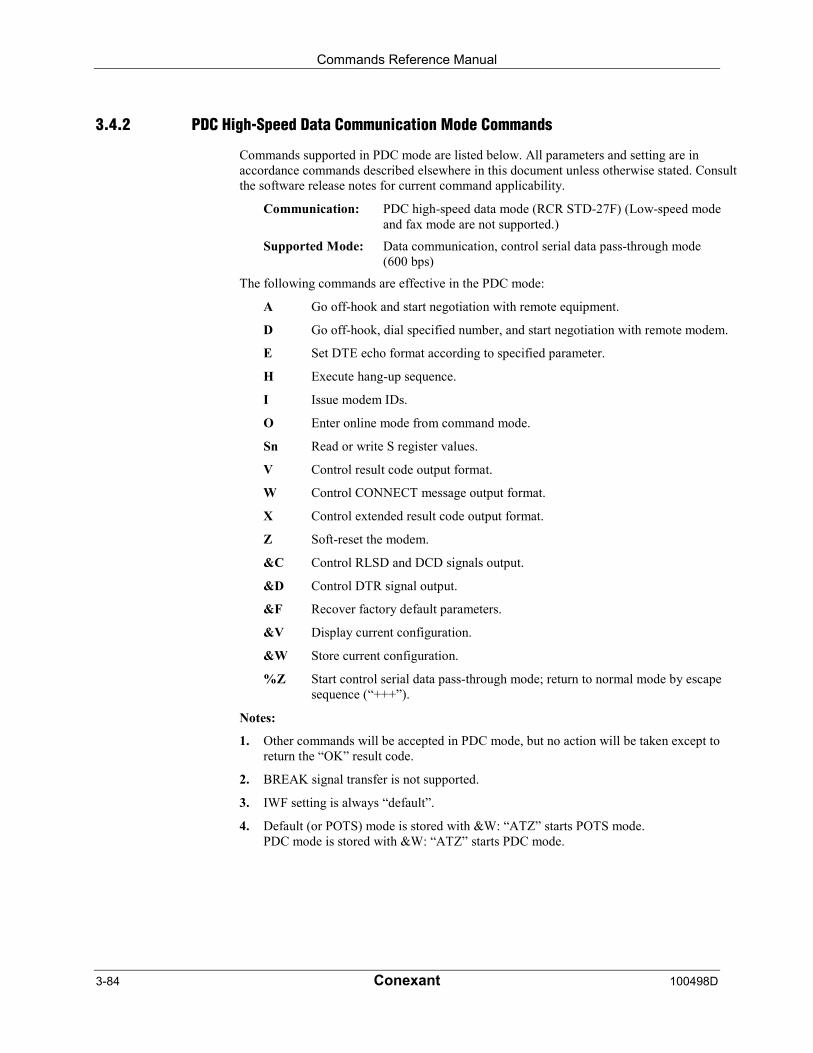
Commands Reference Manual
3-84 Conexant 100498D
3.4.2 PDC High-Speed Data Communication Mode Commands
Commands supported in PDC mode are listed below. All parameters and setting are inaccordance commands described elsewhere in this document unless otherwise stated. Consultthe software release notes for current command applicability.
Communication: PDC high-speed data mode (RCR STD-27F) (Low-speed modeand fax mode are not supported.)
Supported Mode: Data communication, control serial data pass-through mode(600 bps)
The following commands are effective in the PDC mode:
A Go off-hook and start negotiation with remote equipment.
D Go off-hook, dial specified number, and start negotiation with remote modem.
E Set DTE echo format according to specified parameter.
H Execute hang-up sequence.
I Issue modem IDs.
O Enter online mode from command mode.
Sn Read or write S register values.
V Control result code output format.
W Control CONNECT message output format.
X Control extended result code output format.
Z Soft-reset the modem.
&C Control RLSD and DCD signals output.
&D Control DTR signal output.
&F Recover factory default parameters.
&V Display current configuration.
&W Store current configuration.
%Z Start control serial data pass-through mode; return to normal mode by escapesequence (“+++”).
Notes:
1. Other commands will be accepted in PDC mode, but no action will be taken except toreturn the “OK” result code.
2. BREAK signal transfer is not supported.
3. IWF setting is always “default”.
4. Default (or POTS) mode is stored with &W: “ATZ” starts POTS mode.PDC mode is stored with &W: “ATZ” starts PDC mode.
Commands Reference Manual
100498D Conexant 3-85
3.5 Result Codes
The modem responds to commands from the DTE and to activity on the line by signaling tothe DTE in the form of result codes. The result codes that the modem can send are describedin Table 3-15.
Two forms of each result code are available: long-form, an English-like "verbose" response,and short-form, a data-like numeric response (included in parentheses following the long-form). The long-form code is preceded and terminated by the sequence < CR> < LF>. Theshort-form is terminated by < CR>, only with no preceding sequence.
If result messages are suppressed, nothing is returned to the DTE. The long-form results codescan be modified by the OEM through the .INF file.
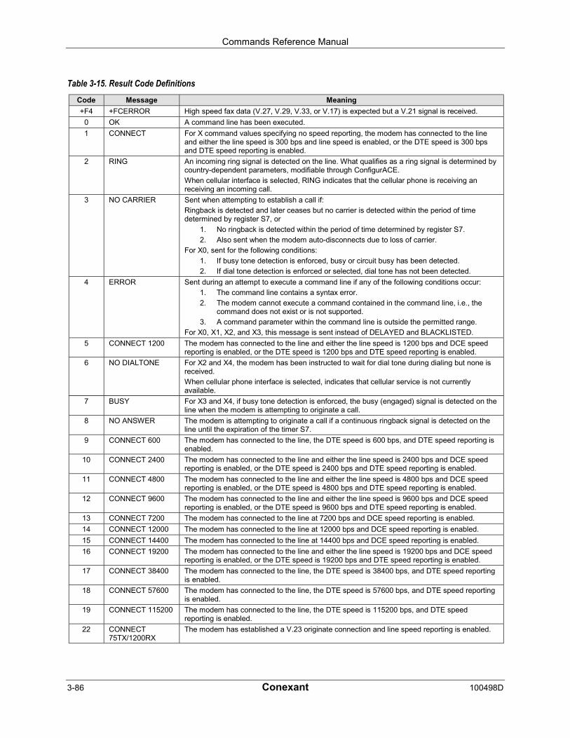
Commands Reference Manual
3-86 Conexant 100498D
Table 3-15. Result Code DefinitionsCode Message Meaning
+F4 +FCERROR High speed fax data (V.27, V.29, V.33, or V.17) is expected but a V.21 signal is received.
0 OK A command line has been executed.
1 CONNECT For X command values specifying no speed reporting, the modem has connected to the lineand either the line speed is 300 bps and line speed is enabled, or the DTE speed is 300 bpsand DTE speed reporting is enabled.
2 RING An incoming ring signal is detected on the line. What qualifies as a ring signal is determined bycountry-dependent parameters, modifiable through ConfigurACE.
When cellular interface is selected, RING indicates that the cellular phone is receiving anreceiving an incoming call.
3 NO CARRIER Sent when attempting to establish a call if:
Ringback is detected and later ceases but no carrier is detected within the period of timedetermined by register S7, or
1. No ringback is detected within the period of time determined by register S7.
2. Also sent when the modem auto-disconnects due to loss of carrier.
For X0, sent for the following conditions:
1. If busy tone detection is enforced, busy or circuit busy has been detected.
2. If dial tone detection is enforced or selected, dial tone has not been detected.
4 ERROR Sent during an attempt to execute a command line if any of the following conditions occur:
1. The command line contains a syntax error.
2. The modem cannot execute a command contained in the command line, i.e., thecommand does not exist or is not supported.
3. A command parameter within the command line is outside the permitted range.
For X0, X1, X2, and X3, this message is sent instead of DELAYED and BLACKLISTED.
5 CONNECT 1200 The modem has connected to the line and either the line speed is 1200 bps and DCE speedreporting is enabled, or the DTE speed is 1200 bps and DTE speed reporting is enabled.
6 NO DIALTONE For X2 and X4, the modem has been instructed to wait for dial tone during dialing but none isreceived.
When cellular phone interface is selected, indicates that cellular service is not currentlyavailable.
7 BUSY For X3 and X4, if busy tone detection is enforced, the busy (engaged) signal is detected on theline when the modem is attempting to originate a call.
8 NO ANSWER The modem is attempting to originate a call if a continuous ringback signal is detected on theline until the expiration of the timer S7.
9 CONNECT 600 The modem has connected to the line, the DTE speed is 600 bps, and DTE speed reporting isenabled.
10 CONNECT 2400 The modem has connected to the line and either the line speed is 2400 bps and DCE speedreporting is enabled, or the DTE speed is 2400 bps and DTE speed reporting is enabled.
11 CONNECT 4800 The modem has connected to the line and either the line speed is 4800 bps and DCE speedreporting is enabled, or the DTE speed is 4800 bps and DTE speed reporting is enabled.
12 CONNECT 9600 The modem has connected to the line and either the line speed is 9600 bps and DCE speedreporting is enabled, or the DTE speed is 9600 bps and DTE speed reporting is enabled.
13 CONNECT 7200 The modem has connected to the line at 7200 bps and DCE speed reporting is enabled.
14 CONNECT 12000 The modem has connected to the line at 12000 bps and DCE speed reporting is enabled.
15 CONNECT 14400 The modem has connected to the line at 14400 bps and DCE speed reporting is enabled.
16 CONNECT 19200 The modem has connected to the line and either the line speed is 19200 bps and DCE speedreporting is enabled, or the DTE speed is 19200 bps and DTE speed reporting is enabled.
17 CONNECT 38400 The modem has connected to the line, the DTE speed is 38400 bps, and DTE speed reportingis enabled.
18 CONNECT 57600 The modem has connected to the line, the DTE speed is 57600 bps, and DTE speed reportingis enabled.
19 CONNECT 115200 The modem has connected to the line, the DTE speed is 115200 bps, and DTE speedreporting is enabled.
22 CONNECT75TX/1200RX
The modem has established a V.23 originate connection and line speed reporting is enabled.
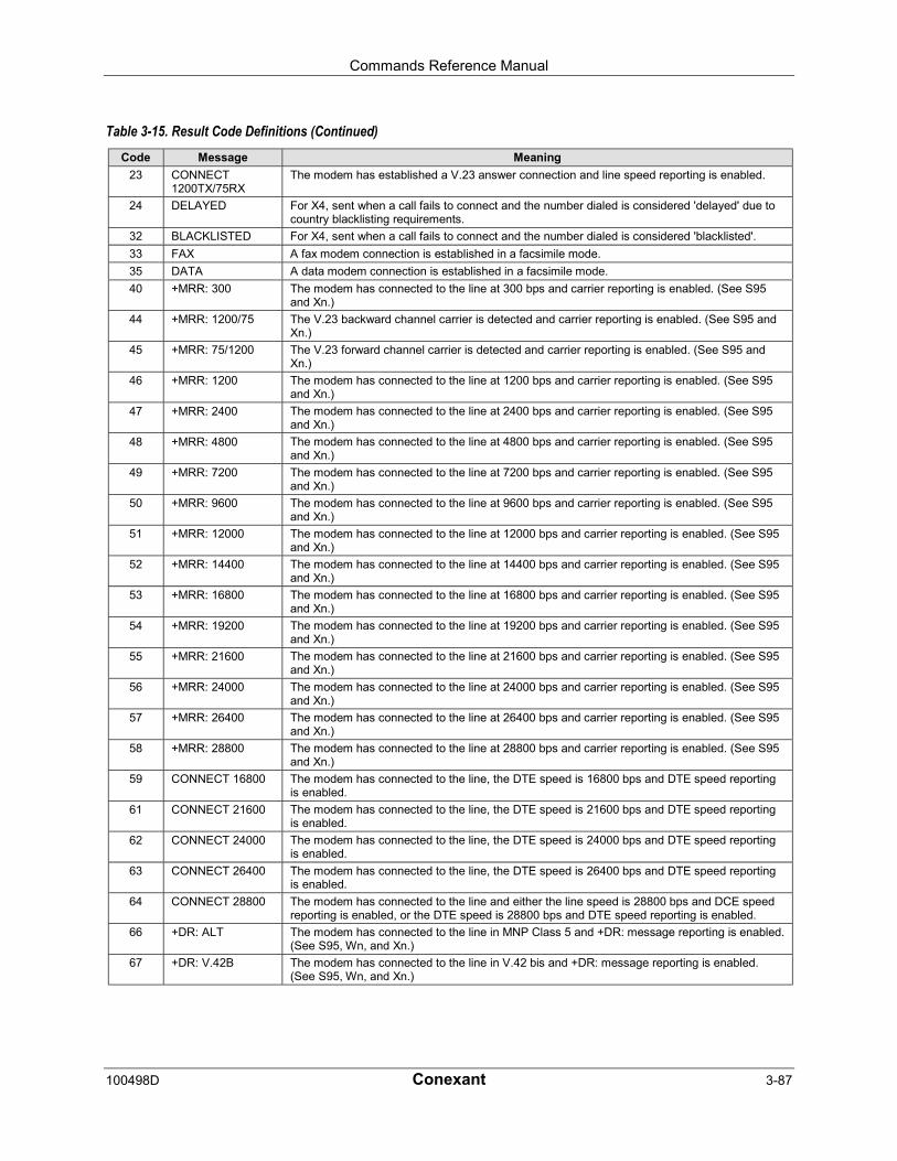
Commands Reference Manual
100498D Conexant 3-87
Table 3-15. Result Code Definitions (Continued)Code Message Meaning
23 CONNECT1200TX/75RX
The modem has established a V.23 answer connection and line speed reporting is enabled.
24 DELAYED For X4, sent when a call fails to connect and the number dialed is considered 'delayed' due tocountry blacklisting requirements.
32 BLACKLISTED For X4, sent when a call fails to connect and the number dialed is considered 'blacklisted'.
33 FAX A fax modem connection is established in a facsimile mode.
35 DATA A data modem connection is established in a facsimile mode.
40 +MRR: 300 The modem has connected to the line at 300 bps and carrier reporting is enabled. (See S95and Xn.)
44 +MRR: 1200/75 The V.23 backward channel carrier is detected and carrier reporting is enabled. (See S95 andXn.)
45 +MRR: 75/1200 The V.23 forward channel carrier is detected and carrier reporting is enabled. (See S95 andXn.)
46 +MRR: 1200 The modem has connected to the line at 1200 bps and carrier reporting is enabled. (See S95and Xn.)
47 +MRR: 2400 The modem has connected to the line at 2400 bps and carrier reporting is enabled. (See S95and Xn.)
48 +MRR: 4800 The modem has connected to the line at 4800 bps and carrier reporting is enabled. (See S95and Xn.)
49 +MRR: 7200 The modem has connected to the line at 7200 bps and carrier reporting is enabled. (See S95and Xn.)
50 +MRR: 9600 The modem has connected to the line at 9600 bps and carrier reporting is enabled. (See S95and Xn.)
51 +MRR: 12000 The modem has connected to the line at 12000 bps and carrier reporting is enabled. (See S95and Xn.)
52 +MRR: 14400 The modem has connected to the line at 14400 bps and carrier reporting is enabled. (See S95and Xn.)
53 +MRR: 16800 The modem has connected to the line at 16800 bps and carrier reporting is enabled. (See S95and Xn.)
54 +MRR: 19200 The modem has connected to the line at 19200 bps and carrier reporting is enabled. (See S95and Xn.)
55 +MRR: 21600 The modem has connected to the line at 21600 bps and carrier reporting is enabled. (See S95and Xn.)
56 +MRR: 24000 The modem has connected to the line at 24000 bps and carrier reporting is enabled. (See S95and Xn.)
57 +MRR: 26400 The modem has connected to the line at 26400 bps and carrier reporting is enabled. (See S95and Xn.)
58 +MRR: 28800 The modem has connected to the line at 28800 bps and carrier reporting is enabled. (See S95and Xn.)
59 CONNECT 16800 The modem has connected to the line, the DTE speed is 16800 bps and DTE speed reportingis enabled.
61 CONNECT 21600 The modem has connected to the line, the DTE speed is 21600 bps and DTE speed reportingis enabled.
62 CONNECT 24000 The modem has connected to the line, the DTE speed is 24000 bps and DTE speed reportingis enabled.
63 CONNECT 26400 The modem has connected to the line, the DTE speed is 26400 bps and DTE speed reportingis enabled.
64 CONNECT 28800 The modem has connected to the line and either the line speed is 28800 bps and DCE speedreporting is enabled, or the DTE speed is 28800 bps and DTE speed reporting is enabled.
66 +DR: ALT The modem has connected to the line in MNP Class 5 and +DR: message reporting is enabled.(See S95, Wn, and Xn.)
67 +DR: V.42B The modem has connected to the line in V.42 bis and +DR: message reporting is enabled.(See S95, Wn, and Xn.)

Commands Reference Manual
3-88 Conexant 100498D
Table 3-15. Result Code Definitions (Continued)Code Message Meaning
69 +DR: NONE The modem has connected to the line without data compression and +DR: message reportingis enabled. (See S95, Wn, and Xn.)
70 +ER: NONE The modem has connected to the line without any form of error correction and the +ER:message reporting has been enabled. (See S95, Wn, and Xn.)
77 +ER: LAPM The modem has connected to the line in V.42 LAPM error correction mode and +ER: messagereporting has been enabled. (See S95, Wn, and Xn.)
78 +MRR: 31200 The modem has connected to the line at 31200 bps and carrier reporting is enabled. (See S95and Xn.)
79 +MRR: 33600 The modem has connected to the line at 33600 bps and carrier reporting is enabled. (See S95and Xn.)
80 +ER: ALT Sent when the modem has connected in the MNP mode of error correction, and +ER: messagereporting has been enabled. (See S95, Wn, and Xn.)
83 LINE IN USE The modem attempted to go off-hook when an extension was already occupying the line.
84 CONNECT 33600 The modem has connected to the line, the DTE speed is 33600 bps and the DTE speedreporting is enabled.
91 CONNECT 31200 The modem has connected to the line DTE speed is 31200 bps and the modem is to report theDTE speed upon connecting.
134 +MCR: B103 The modem has connected to the line with Bell 103 modulation and modulation reporting isenabled. (See +MR, S95 and Xn.)
135 +MCR: B212 The modem has connected to the line with Bell 212 modulation and modulation reporting isenabled. (See +MR, S95 and Xn.)
136 +MCR: V21 The modem has connected to the line with ITU-T V.21 modulation and modulation reporting isenabled. (See +MR, S95 and Xn.)
137 +MCR: V22 The modem has connected to the line with ITU-T V.22 modulation and modulation reporting isenabled. (See +MR, S95 and Xn.)
138 +MCR: V22B The modem has connected to the line with ITU-T V.22 bis modulation and modulation reportingis enabled. (See +MR, S95 and Xn.)
139 +MCR: V23 The modem has connected to the line with ITU-T V.23 modulation and modulation reporting isenabled. (See +MR, S95 and Xn.)
140 +MCR: V32 The modem has connected to the line with ITU-T V.32 modulation and modulation reporting isenabled. (See +MR, S95 and Xn.)
141 +MCR: V32B The modem has connected to the line with ITU-T V.32 bis modulation and modulation reportingis enabled. (See +MR, S95 and Xn.)
142 +MCR: V34 The modem has connected to the line with ITU-T V.34 modulation and modulation reporting isenabled. (See +MR, S95 and Xn.)
144 +MCR: K56 The modem has connected to the line with K56flex modulation and modulation reporting isenabled. (See +MR, S95 and Xn.)
145 +MCR: V90 The modem has connected to the line with ITU-T V.90 modulation and modulation reporting isenabled. (See +MR, S95 and Xn.)
150 +MRR: 32000 The modem has connected to the line at 32000 bps and carrier reporting is enabled. (See S95and Xn.)
151 +MRR: 34000 The modem has connected to the line at 34000 bps and carrier reporting is enabled. (See S95and Xn.)
152 +MRR: 36000 The modem has connected to the line at 36000 bps and carrier reporting is enabled. (See S95and Xn.)
153 +MRR: 38000 The modem has connected to the line at 38000 bps and carrier reporting is enabled. (See S95and Xn.)
154 +MRR: 40000 The modem has connected to the line at 40000 bps and carrier reporting is enabled. (See S95and Xn.)
155 +MRR: 42000 The modem has connected to the line at 42000 bps and carrier reporting is enabled. (See S95and Xn.)
156 +MRR: 44000 The modem has connected to the line at 44000 bps and carrier reporting is enabled. (See S95and Xn.)
157 +MRR: 46000 The modem has connected to the line at 46000 bps and carrier reporting is enabled. (See S95and Xn.)
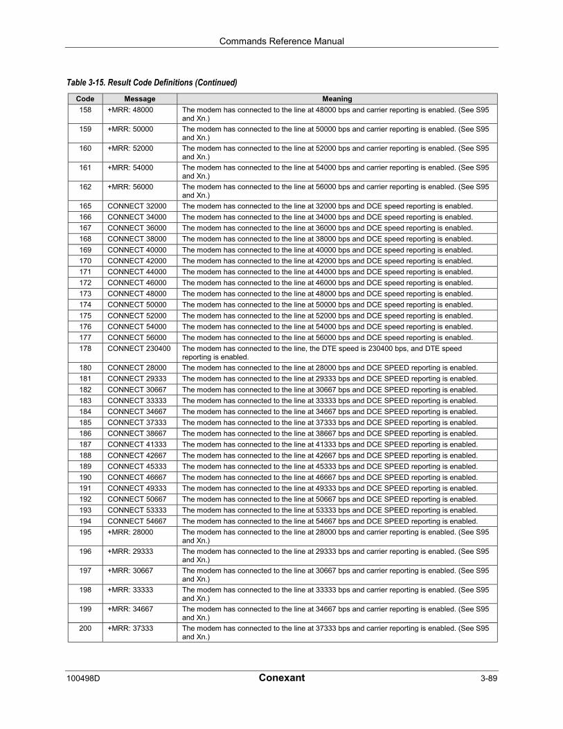
Commands Reference Manual
100498D Conexant 3-89
Table 3-15. Result Code Definitions (Continued)Code Message Meaning
158 +MRR: 48000 The modem has connected to the line at 48000 bps and carrier reporting is enabled. (See S95and Xn.)
159 +MRR: 50000 The modem has connected to the line at 50000 bps and carrier reporting is enabled. (See S95and Xn.)
160 +MRR: 52000 The modem has connected to the line at 52000 bps and carrier reporting is enabled. (See S95and Xn.)
161 +MRR: 54000 The modem has connected to the line at 54000 bps and carrier reporting is enabled. (See S95and Xn.)
162 +MRR: 56000 The modem has connected to the line at 56000 bps and carrier reporting is enabled. (See S95and Xn.)
165 CONNECT 32000 The modem has connected to the line at 32000 bps and DCE speed reporting is enabled.
166 CONNECT 34000 The modem has connected to the line at 34000 bps and DCE speed reporting is enabled.
167 CONNECT 36000 The modem has connected to the line at 36000 bps and DCE speed reporting is enabled.
168 CONNECT 38000 The modem has connected to the line at 38000 bps and DCE speed reporting is enabled.
169 CONNECT 40000 The modem has connected to the line at 40000 bps and DCE speed reporting is enabled.
170 CONNECT 42000 The modem has connected to the line at 42000 bps and DCE speed reporting is enabled.
171 CONNECT 44000 The modem has connected to the line at 44000 bps and DCE speed reporting is enabled.
172 CONNECT 46000 The modem has connected to the line at 46000 bps and DCE speed reporting is enabled.
173 CONNECT 48000 The modem has connected to the line at 48000 bps and DCE speed reporting is enabled.
174 CONNECT 50000 The modem has connected to the line at 50000 bps and DCE speed reporting is enabled.
175 CONNECT 52000 The modem has connected to the line at 52000 bps and DCE speed reporting is enabled.
176 CONNECT 54000 The modem has connected to the line at 54000 bps and DCE speed reporting is enabled.
177 CONNECT 56000 The modem has connected to the line at 56000 bps and DCE speed reporting is enabled.
178 CONNECT 230400 The modem has connected to the line, the DTE speed is 230400 bps, and DTE speedreporting is enabled.
180 CONNECT 28000 The modem has connected to the line at 28000 bps and DCE SPEED reporting is enabled.
181 CONNECT 29333 The modem has connected to the line at 29333 bps and DCE SPEED reporting is enabled.
182 CONNECT 30667 The modem has connected to the line at 30667 bps and DCE SPEED reporting is enabled.
183 CONNECT 33333 The modem has connected to the line at 33333 bps and DCE SPEED reporting is enabled.
184 CONNECT 34667 The modem has connected to the line at 34667 bps and DCE SPEED reporting is enabled.
185 CONNECT 37333 The modem has connected to the line at 37333 bps and DCE SPEED reporting is enabled.
186 CONNECT 38667 The modem has connected to the line at 38667 bps and DCE SPEED reporting is enabled.
187 CONNECT 41333 The modem has connected to the line at 41333 bps and DCE SPEED reporting is enabled.
188 CONNECT 42667 The modem has connected to the line at 42667 bps and DCE SPEED reporting is enabled.
189 CONNECT 45333 The modem has connected to the line at 45333 bps and DCE SPEED reporting is enabled.
190 CONNECT 46667 The modem has connected to the line at 46667 bps and DCE SPEED reporting is enabled.
191 CONNECT 49333 The modem has connected to the line at 49333 bps and DCE SPEED reporting is enabled.
192 CONNECT 50667 The modem has connected to the line at 50667 bps and DCE SPEED reporting is enabled.
193 CONNECT 53333 The modem has connected to the line at 53333 bps and DCE SPEED reporting is enabled.
194 CONNECT 54667 The modem has connected to the line at 54667 bps and DCE SPEED reporting is enabled.
195 +MRR: 28000 The modem has connected to the line at 28000 bps and carrier reporting is enabled. (See S95and Xn.)
196 +MRR: 29333 The modem has connected to the line at 29333 bps and carrier reporting is enabled. (See S95and Xn.)
197 +MRR: 30667 The modem has connected to the line at 30667 bps and carrier reporting is enabled. (See S95and Xn.)
198 +MRR: 33333 The modem has connected to the line at 33333 bps and carrier reporting is enabled. (See S95and Xn.)
199 +MRR: 34667 The modem has connected to the line at 34667 bps and carrier reporting is enabled. (See S95and Xn.)
200 +MRR: 37333 The modem has connected to the line at 37333 bps and carrier reporting is enabled. (See S95and Xn.)
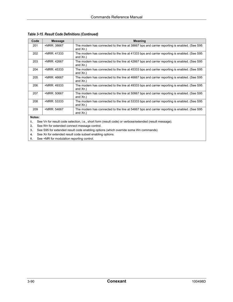
Commands Reference Manual
3-90 Conexant 100498D
Table 3-15. Result Code Definitions (Continued)Code Message Meaning
201 +MRR: 38667 The modem has connected to the line at 38667 bps and carrier reporting is enabled. (See S95and Xn.)
202 +MRR: 41333 The modem has connected to the line at 41333 bps and carrier reporting is enabled. (See S95and Xn.)
203 +MRR: 42667 The modem has connected to the line at 42667 bps and carrier reporting is enabled. (See S95and Xn.)
204 +MRR: 45333 The modem has connected to the line at 45333 bps and carrier reporting is enabled. (See S95and Xn.)
205 +MRR: 46667 The modem has connected to the line at 46667 bps and carrier reporting is enabled. (See S95and Xn.)
206 +MRR: 49333 The modem has connected to the line at 49333 bps and carrier reporting is enabled. (See S95and Xn.)
207 +MRR: 50667 The modem has connected to the line at 50667 bps and carrier reporting is enabled. (See S95and Xn.)
208 +MRR: 53333 The modem has connected to the line at 53333 bps and carrier reporting is enabled. (See S95and Xn.)
209 +MRR: 54667 The modem has connected to the line at 54667 bps and carrier reporting is enabled. (See S95and Xn.)
Notes:
1. See Vn for result code selection, i.e., short form (result code) or verbose/extended (result message).
2. See Wn for extended connect message control.
3. See S95 for extended result code enabling options (which override some Wn commands).
4. See Xn for extended result code subset enabling options.
5. See +MR for modulation reporting control.
Commands Reference Manual
100498D Conexant 4-1
4 Fax Class 1 and Fax Class 1.0 Commands
4.1 Fax I/O Processing
The fax I/O interface supports asynchronous serial and parallel interfaces. The characterformat is 8 bits data, no parity, and 1 stop bit. Start and stop elements are removed from thetransmit data and added to the receive data. Both transmit and receive data are buffered. Flowcontrol using XON/XOFF or RTS/CTS is provided.
Unique control character strings are identified, filtered, or reinserted into the I/O data stream.These control characters and their resultant action are described below.
4.1.1 DTE-to-Modem Transmit Data Stream
Characters Detected Action Taken
<DLE><data> Delete <DLE><data> characters.
<DLE><ETX> Recognize as a string terminator and take appropriate action.
<DLE><DLE> Replace with single <DLE> character.
4.1.2 Modem-to-DTE Receive Data Stream
Characters Detected Action Taken
<DLE> Insert extra <DLE> ahead of <DLE>.
The modem also identifies the end of a frame by inserting <DLE><ETX> into the data streamafter the FCS bytes.
4.1.3 Fax Mode Selection
Fax Class 1 and Fax Class 1.0 commands are identified in Table 4-1. Fax Class 1.0 includesall Fax Class 1 commands.

Commands Reference Manual
4-2 Conexant 100498D
Table 4-1. Fax Class 1 and Fax Class 1.0 CommandsCommand/Parameter Function Applicable in
Fax Class 1Applicable inFax Class 1.0
+FCLASS=<class> Select, read or test service class X X
+FAE=<value> Auto answer enable X X
+FTS=<time> Stop transmission and pause X X
+FRS=<time> Wait for silence X X
+FTM=<mod> Transmit data with <mod> carrier X X
+FRM=<mod> Receive data with <mod> carrier X X
+FTH=<mod> Transmit HDLC data with <mod> carrier X X
+FRH=<mod> Receive HDLC data with <mod> carrier X X
+FAR=<off/on> Adaptive reception control - X
+FCL=<time> Carrier loss timeout - X
+FDD=<value> Double escape character replacement control - X
+FIT=<time>, <action> DTE inactivity timeout - X
+FPR=<rate> Fixed DTE Rate - X
+FMI Report manufacturer ID - X
+FMM Report model ID - X
+FMR Report revision ID - X
+FLO Flow Control - X
+IFC Local DTE-modem flow control (see +IFC command inSection 3.2.1)
X X
A Answer (see A command in Section 3.2.3) X X
D <string> Dial (see D command in Section 3.2.3) X X
H Hangup (see H command in Section 3.2.3) X X
X = Applicable; - = Not applicable
Commands Reference Manual
100498D Conexant 4-3
4.1.4 Fax Origination
Origination of fax calls is made using the ATD command. Upon completion of the dialfunction, a calling tone at 1100 Hz is transmitted, with a cadence of 0.5 seconds on and 3seconds off. The modem automatically enters mode +FRH=3 and sends the CONNECTmessage to the DTE when FSK flags are detected from the remote.
4.1.5 Fax Answering
Answering of fax calls is identical to answering of data calls with the exception that themodem enters the fax handshaking mode instead of the data handshaking mode after goingoff-hook. If +FAE=0, the modem, after sending answer tone, automatically enters fax mode(+FTH=3), sends the CONNECT message to the DTE, and starts sending FSK flags. If+FAE=1, the modem determines whether the caller is a data modem or fax modem and sendsthe DATA or FAX result code, respectively, to the DTE.
4.1.6 Fax Control Transmission
Fax control transmission is initiated by the +FTH=<mod> command. After this command isissued, the modem generates the CONNECT message and transmits carrier in the modulationscheme specified by the parameter n. The modem then transmits HDLC flags for a minimumof 1 second. The modem continues to transmit the HDLC flags until it receives a characterfrom the DTE.
When characters are received from the DTE, the modem adds start and end flags, performszero-bit insertion, generates FCS, and deletes <DLE><chr> character pairs beforetransmitting the characters to the remote fax machine. Each <DLE><DLE> sequence istransmitted as a single <DLE>. <DLE><ETX> is considered as the end of frame marker andis not transmitted. All data received from the DTE after <DLE><ETX> is ignored by themodem until the modem generates either the CONNECT, OK, or ERROR result code.
If no more data is in the transmit buffer and the final bit was a 1 (bit 4 of the second bytereceived from the DTE), the modem generates the OK result code and returns to the commandmode. If the final bit was a 0, the modem generates the CONNECT message and waits forfurther data from the DTE while transmitting HDLC flags. If no more data is received before5 seconds elapse, the modem drops carrier, goes on-hook, and generates the ERROR resultcode.
4.1.7 Fax Control Reception
Fax control reception is initiated using the AT+FRH=<mod> command. After this commandis issued, the modem looks for carrier in the modulation scheme specified by the parameter n.If no carrier is detected before the period of time specified by register S7 expires, the modemgenerates the NO CARRIER message and returns to command mode. If a carrier is detectedthat is not the one specified by the parameter n, the modem generates the +FCERRORmessage and returns to the command mode. If the specified carrier is detected, the modemgenerates the CONNECT message and enters the HDLC receive mode.
In HDLC receive mode, the modem receives HDLC frames from the remote fax machine,strips the flags, performs zero-bit deletion, performs error checking, and handles<DLE><chr> character pairs before passing the data to the DTE. The modem prefixes each<DLE> character with another <DLE> character before sending it to the DTE. After the lastbyte in the frame, the modem sends <DLE><ETX> to the DTE marking the end of the frame.

Commands Reference Manual
4-4 Conexant 100498D
The modem then generates either the OK message if no errors were detected or the ERRORmessage if errors were detected (FCS is incorrect), and returns to command mode.
While in command mode, the modem continues to receive data in the selected modulationscheme, and sends the data after sending the CONNECT message to the DTE when the DTEreissues the +FRH command with the same parameter. If the DTE issues the +FRH commandwith a different parameter, the modem clears all buffers and proceeds as described previously.
If carrier is lost while in command mode and the DTE reissues the +FRH command with thesame parameter, and there is no data in the buffer, the modem sends the ERROR result codeto the DTE and returns to the command mode. If there is data in the buffer, the modem sendsthe next frame of buffered data to the DTE, followed by <DLE><ETX>, and either theERROR result code if errors were detected or the OK result code if no errors were detected.The modem then returns to command mode.
The modem concludes an error is detected if carrier is lost for any period of time during orbefore the reception of a frame. If carrier is lost for a time period longer than the timespecified by the register S10, the modem finishes delivering the data in the receive buffer (ifany) to the DTE, sends <DLE><ETX>, generates the ERROR message, and returns tocommand mode. All subsequent data received from the remote is discarded.
If the modem detects a frame abort sequence (seven consecutive ones with no zero insertion)while it is waiting for a frame beginning flag (it was receiving HDLC flags), it will wait forthe HDLC flags again until either carrier is lost, or the DTE aborts the process by sending anabort character or by dropping DTR with &D2 in effect. If the frame abort sequence isdetected while the modem is receiving a frame it finishes delivering the data in the receivebuffer (if any) to the DTE, sends <DLE><ETX>, generates the ERROR message, and returnsto command mode. The modem keeps looking for HDLC flags followed by more data fromthe remote, with the selected modulation scheme.
If the modem detects a receive buffer overflow condition, it concludes that there was an FCSerror in that frame. The modem will receive more frames only if a starting flag is detected andthere is room in the receive buffer. If a starting flag is detected and there is no room in thebuffer, the modem discards all data in that frame.
If the modem receives any character from the DTE after the +FRH command (except flowcontrol characters if software flow control is in effect), or if the modem detects a high-to-lowtransition of the DTR signal while &D1 is in effect, it sends <DLE><ETX> to the DTE,generates OK result code, and returns to command mode. The receive buffer is cleared and alldata received from the remote is discarded. If the modem detects a DTR drop while &D2 is ineffect, it goes on-hook, sends <DLE><ETX> to the DTE, generates OK result code, andreturns to command mode. If the modem detects a DTR drop while &D3 is in effect, themodem performs a warm reset.
4.1.8 Fax Data Transmission
Fax data transmission is initiated by the AT+FTM=<mod> command. After this command isissued, the modem generates the CONNECT message and transmits carrier in the modulationscheme specified by the parameter n. The modem then transmits constant 1 bits for aminimum of one second and continues to transmit constant 1 bits until it receives a characterfrom the DTE.
When data is received from the DTE, the modem deletes start and stop bits and deletes all<DLE><chr> character pairs before transmitting the data to the remote. Each <DLE><DLE>sequence is transmitted as a single <DLE>. <DLE><ETX> is considered as the end of streammarker, and is not transmitted. All data received from the DTE after the <DLE><ETX> isignored by the modem until the modem generates either the CONNECT, OK, or ERRORresult code.
Commands Reference Manual
100498D Conexant 4-5
If no more data is in the transmit buffer, and the last transmitted character was not an ASCIINULL, the modem generates the OK result code and returns to the command mode. If the lastcharacter transmitted was an ASCII NULL, the modem generates the CONNECT message tothe DTE and waits for further data from the DTE while transmitting NULLs to the remote. Ifmore data is received before five seconds elapse, the modem continues to transmit the data asdescribed in the previous paragraph. If five seconds elapse and no data is received from theDTE, the modem drops carrier, goes on-hook, and generates the ERROR result code.
4.1.9 Fax Data Reception
Fax data reception is initiated using the AT+FRM=<mod> command. After this command isissued, the modem looks for carrier in the modulation scheme specified by the parameter n. Ifno carrier is detected before the period of time specified by register S7 expires, the modemgenerates the NO CARRIER message and returns to command mode. If a V.21 carrier isdetected when a high speed carrier is expected, the modem generates the +FCERRORmessage and returns to the command mode. If the specified carrier is detected, the modemgenerates the CONNECT message and enters the data receive mode.
While in data receive mode, the modem receives data from the remote, adds start and stopbits, and handles <DLE><chr> character pairs before passing the data to the DTE. Themodem prefixes each <DLE> character with another <DLE> character before sending it to theDTE.
If the modem detects a receive buffer overflow condition, it stops receiving from the remoteuntil there is room in the receive buffer. The modem informs the DTE of the buffer overflowafter it sends to the DTE the last character that was stored in the buffer before the overflowoccurred.
If the modem receives any character from the DTE after the +FRM command (except flowcontrol characters if software flow control is in effect), or if the modem detects a high-to-lowtransition of the DTR signal while &D1 is in effect, it sends <DLE><ETX> to the DTE,generates the OK result code, and returns to command mode. The receive buffer is clearedand all data received from the remote is discarded. If loss of DTR is detected while &D2 is ineffect, the modem goes on-hook, sends <DLE><ETX> followed by OK result code to theDTE, and returns to command mode. If the modem detects a DTR drop while &D3 is ineffect, the modem performs a warm reset.

Commands Reference Manual
4-6 Conexant 100498D
4.2 Commands and Parameters
4.2.1 Mode Entry Commands
+FCLASS=1 - Select Facsimile Class 1 Mode
+FCLASS=1 selects the Fax Class 1 Mode. The Fax Class 1 Mode commands and responsesdescribed in this section are applicable when command +FCLASS=1 as shown in Table 4-1.(See +FCLASS in Section 3.2.1 for the definition of the FCLASS command.)
+FCLASS=1.0 - Select Facsimile Class 1.0 Mode
+FCLASS=1.0 selects the Fax Class 1.0 Mode. The Fax Class 1.0 Mode commands andresponses described in this section are applicable when command +FCLASS=1 as shownTable 4-1. (See +FCLASS in Section 3.2.1 for the definition of the FCLASS command.)
4.2.2 Mode Commands
+FAE - Auto Answer Enable
This command enables or disables fax adaptive answer.
Syntax
+FAE=<value>
Defined Values
<value> Decimal number corresponding to the selected option.
0 Disable data /fax auto answer mode. (Default.)
1 Enable data /fax auto answer mode. The modemdetermines the calling type and issues DATA resultcode (13) if the caller is a data modem or issues FAXresult code (15) if the caller is a fax modem.

Commands Reference Manual
100498D Conexant 4-7
+FTS - Transmit Silence
This command causes the modem to terminate a transmission and wait for <time> 10-msintervals before responding with the OK result code.
Syntax
+FTS=<time>
Defined Values
<time> Decimal number from 0 (default) to 255 which specifies the lengthof time in 10-ms intervals to delay before responding with the OKresult code after terminating the session.
Result Codes
OK Reported when transmission has been terminated for the specifiedamount of time.
ERROR <value> is invalid or this command is issued while the modem ison-hook.
Reporting Supported Range of Parameter Values
Command: +FTS=?
Response: +FTS: <time> range
Example: +FTS: 0-255

Commands Reference Manual
4-8 Conexant 100498D
+FRS - Receive Silence
This command causes the modem to listen and report an OK result code when silence hasbeen detected on the line for the specified period of time. This command will terminate whenthe required period of silence is detected or when the DTE sends the modem another characterother than XON or XOFF, which is discarded. In either event, the OK result code is returned.
This command is aborted if any character is received from the DTE after receipt of thecommand but before the time delay elapses. In this case, the modem discards the abortingcharacter and issues an OK result code.
Syntax
+FRS =<time>
Defined Values
<time> Decimal number from 0 (default) to 255 which specifies the lengthof time in 10-ms intervals to delay before responding with the OKresult code after detecting silence on the line.
Result Codes
OK Reported when silence has been present on the line for thespecified amount of time or when the DTE sends the modem acharacter other than XON or XOFF.
ERROR <value> is invalid or this command is issued while the modem ison-hook.
Reporting Supported Range of Parameter Values
Command: +FRS=?
Response: +FRS: <time> range
Example: +FRS: 0-255
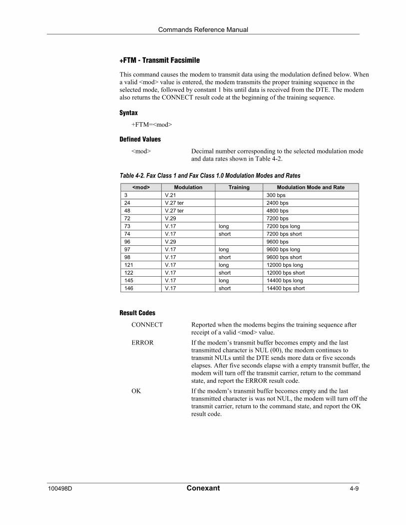
Commands Reference Manual
100498D Conexant 4-9
+FTM - Transmit Facsimile
This command causes the modem to transmit data using the modulation defined below. Whena valid <mod> value is entered, the modem transmits the proper training sequence in theselected mode, followed by constant 1 bits until data is received from the DTE. The modemalso returns the CONNECT result code at the beginning of the training sequence.
Syntax
+FTM=<mod>
Defined Values
<mod> Decimal number corresponding to the selected modulation modeand data rates shown in Table 4-2.
Table 4-2. Fax Class 1 and Fax Class 1.0 Modulation Modes and Rates<mod> Modulation Training Modulation Mode and Rate
3 V.21 300 bps
24 V.27 ter 2400 bps
48 V.27 ter 4800 bps
72 V.29 7200 bps
73 V.17 long 7200 bps long
74 V.17 short 7200 bps short
96 V.29 9600 bps
97 V.17 long 9600 bps long
98 V.17 short 9600 bps short
121 V.17 long 12000 bps long
122 V.17 short 12000 bps short
145 V.17 long 14400 bps long
146 V.17 short 14400 bps short
Result Codes
CONNECT Reported when the modems begins the training sequence afterreceipt of a valid <mod> value.
ERROR If the modem’s transmit buffer becomes empty and the lasttransmitted character is NUL (00), the modem continues totransmit NULs until the DTE sends more data or five secondselapses. After five seconds elapse with a empty transmit buffer, themodem will turn off the transmit carrier, return to the commandstate, and report the ERROR result code.
OK If the modem’s transmit buffer becomes empty and the lasttransmitted character is was not NUL, the modem will turn off thetransmit carrier, return to the command state, and report the OKresult code.
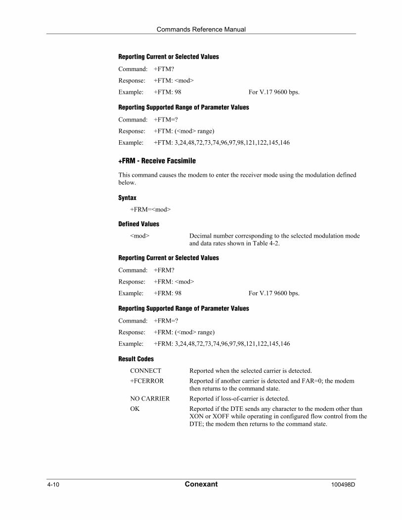
Commands Reference Manual
4-10 Conexant 100498D
Reporting Current or Selected Values
Command: +FTM?
Response: +FTM: <mod>
Example: +FTM: 98 For V.17 9600 bps.
Reporting Supported Range of Parameter Values
Command: +FTM=?
Response: +FTM: (<mod> range)
Example: +FTM: 3,24,48,72,73,74,96,97,98,121,122,145,146
+FRM - Receive Facsimile
This command causes the modem to enter the receiver mode using the modulation definedbelow.
Syntax
+FRM=<mod>
Defined Values
<mod> Decimal number corresponding to the selected modulation modeand data rates shown in Table 4-2.
Reporting Current or Selected Values
Command: +FRM?
Response: +FRM: <mod>
Example: +FRM: 98 For V.17 9600 bps.
Reporting Supported Range of Parameter Values
Command: +FRM=?
Response: +FRM: (<mod> range)
Example: +FRM: 3,24,48,72,73,74,96,97,98,121,122,145,146
Result Codes
CONNECT Reported when the selected carrier is detected.
+FCERROR Reported if another carrier is detected and FAR=0; the modemthen returns to the command state.
NO CARRIER Reported if loss-of-carrier is detected.
OK Reported if the DTE sends any character to the modem other thanXON or XOFF while operating in configured flow control from theDTE; the modem then returns to the command state.
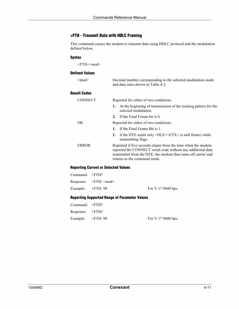
Commands Reference Manual
100498D Conexant 4-11
+FTH - Transmit Data with HDLC Framing
This command causes the modem to transmit data using HDLC protocol and the modulationdefined below.
Syntax
+FTH=<mod>
Defined Values
<mod> Decimal number corresponding to the selected modulation modeand data rates shown in Table 4-2.
Result Codes
CONNECT Reported for either of two conditions:
1. At the beginning of transmission of the training pattern for theselected modulation.
2. If the Final Frame bit is 0.
OK Reported for either of two conditions:
1. If the Final Frame Bit is 1.
2. if the DTE sends only <DLE><ETX> (a null frame) whiletransmitting flags.
ERROR Reported if five seconds elapse from the time when the modemreported the CONNECT result code without any additional datatransmitted from the DTE; the modem then turns off carrier andreturns to the command mode.
Reporting Current or Selected Values
Command: +FTH?
Response: +FTH: <mod>
Example: +FTH: 98 For V.17 9600 bps.
Reporting Supported Range of Parameter Values
Command: +FTH?
Response: +FTH?
Example: +FTH: 98 For V.17 9600 bps.
Commands Reference Manual
4-12 Conexant 100498D
+FRH - Receive Data with HDLC Framing
This command causes the modem to receive frames using HDLC protocol and the modulationdefined below. An ERROR response code results if this command is issued while the modemis on-hook.
Syntax
+FRH=<mod>
Defined Values
<mod> Decimal number corresponding to the selected modulation modeand data rates shown in Table 4-2.
Reporting Current or Selected Values
Command: +FRH?
Response: +FRH: <mod>
Example: +FRH: 98 For V.17 9600 bps.
Reporting Supported Range of Parameter Values
Command: +FRH?
Response: +FRH?
Example: +FRH: 98 For V.17 9600 bps.
Result Codes
CONNECT Reported for either of two conditions:
1. When the selected carrier is detected with an HDLC flag.
2. If the DTE sends another +FTH=<MOD> command aftersending the result code indicating frame reception is complete.
+FCERROR Reported if a different carrier is detected and FAR=0.
NO CARRIER Reported if loss of carrier is detected.
OK Reported for either of two conditions:
1. If a frame was received correctly.
2. If the DTE sends any character other than XON or XOFFwhile the modem is in the configured flow control.
ERROR Reported if a frame was received in error.
Commands Reference Manual
100498D Conexant 4-13
4.2.3 Service Class 1 Parameters
+FAR - Adaptive Reception Control
If Adaptive Reception is enabled, the modem adaptively detects the selected message carrieror V.21 control messages. If the expected carrier is detected, the modem operates as specifiedin the respective +FRM=<mod> or +FRH=<mod> commands. If V.21 flag preamble isdetected instead, the modem issues a +FRH:3 intermediate result code, and then executes animplied +FRH=3 command.
Write Syntax
+FAR=<value>
Defined Values
<value> Decimal number corresponding to the selected option.
0 Disable Adaptive Reception. (Default.)
1 Enable Adaptive Reception.
Reporting Current or Selected Values
Command: +FAR?
Response: +FAR: <value>
Example: +FAR: 0 For the default setting.
Reporting Supported Range of Parameter Values
Command: +FAR=?
Response: +FAR: (<value> range )
Example: +FAR: (0,1)
Commands Reference Manual
4-14 Conexant 100498D
+FCL - Carrier Loss Timeout
This parameter allows the DTE to select the modem’s loss-of-carrier delay between initialloss-of-carrier and qualified loss-of-carrier, when the modem will give up and exit a receivemode. Intermediate (less than FCL timeout) loss-of-carrier should be indicated by insertion ofthe SQ-BAD signal quality indicator in the received data stream.
In unframed receive modes, if the modem detects RTC as described in Recommendation T.30prior to initial loss of the high speed carrier, or if the modem detects V.21 carrier after initialloss of high speed carrier, then the modem immediately accepts the loss-of-carrier asqualified, without waiting for the FCL timer to expire.
In HDLC receive modes, if the modem detects HDLC abort prior to initial loss of the highspeed carrier, or if the modem detects V.21 carrier after initial loss of high speed carrier, thenthe modem l immediately accepts the loss-of-carrier as qualified, without waiting for the FCLtimer to expire.
Write Syntax
+FCL=<time>
Defined Values
<value> Decimal number representing the loss-of-carrier delay time in unitsof 100 ms. The range is 0 - 255.
Reporting Current or Selected Values
Command: +FCL?
Response: +FCL: <time>
Example: +FCS: 0 For the default setting.
Reporting Supported Range of Parameter Values
Command: +FCL=?
Response: +FCL: (<time> range)
Example: +FCL: (0-255)
Commands Reference Manual
100498D Conexant 4-15
+FDD - Double Escape Character Replacement
This parameter conditions the use of the �DLE���SUB� pair to encode consecutive<1/0>€<1/0> in data. This may be used to prevent unbound expansion of data that containsmany <1/0> patterns.
Syntax
+FDD=<value>
Defined Values
<value> Decimal number corresponding to the selected option. For modemdecode of <DLE><SUB>, the defined range are:
0 <DLE> <DLE> or discard (default and only)
1 <DLE> <DLE> (not supported)
For modem encoding of <1/0> <1/0>the defined values are:
0 <DLE> <DLE> <DLE> <DLE> (default and only)
1 <DLE> <SUB> (not supported)
Reporting Current or Selected Values
Command: +FDD?
Response: +FDD: <value>
Example: +FDD: 0 For the default setting.
Reporting Supported Range of Parameter Values
Command: +FDD=?
Response: +FDD: (<value> range)
Example: +FDD: (0)

Commands Reference Manual
4-16 Conexant 100498D
+FIT - DTE Inactivity Timeout
This command specifies a DTE inactivity timeout value that allows the modem to break awayfrom an unsuccessful connection attempt at any stage of a facsimile transfer. The DTEinactivity timer operates only while the modem is off-hook.
Syntax
+FIT=<time>,<action>
Defined Values
<time> The <time> parameter indicates the DTE inactivity timeout inseconds. The value of 0 indicates that timeout is disabled (default).The required timeout range is 1 to 255 seconds. The inactivitytimer starts when the modem has taken some action that requiresDTE response. If the DTE does respond, the modem resets theinactivity timer. Inactivity timer related events are listed in Table4-3.
<action> The <action> parameter has two meanings.
0 Upon timeout, the modem will go on-hook, executingan implied ATH command; then reset to+FCLASS=0.
1 Upon timeout, the DCE will only go on-hook.
Reporting Current or Selected Values
Command: +FIT?
Response: +FIT: <time>,<action>
Example: +FIT: 0,0 For the default settings.
Reporting Supported Range of Parameter Values
Command: +FIT?
Response: +FIT: (<time> range), (<action> range)
Example: +FIT: (0-255),(0-1)
Table 4-3. Inactivity Timer Start and Stop Events
On-Line State Start Timer Event Stop Timer Event
Waiting for a command modem sends final result code DTE sends AT or “at”
Waiting for transmitdata
modem sends CONNECT after+FTM or +FTH command
DTE sends data
Waiting for transmitdata
modem sends <XON> or setsCTS ON
DTE sends data
Waiting to deliverreceived data
modem sends <XOFF> after+FRM or +FRH command
DTE sends <XON>
Waiting to deliverreceived data
DTE sets V.24 Ckt 133 OFF after+FRM or +FRH command
DTE sets V.24 Ckt 133 ON

Commands Reference Manual
100498D Conexant 4-17
+FPR - Fixed DTE Rate
This numeric extended-format parameter specifies the data rate at which the modem willaccept commands during on-line operation. It may be used to select operation at rates atwhich the modem is not capable of automatically detecting the data rate being used by theDTE. Specifying a value of 0 disables the function and allows operation only at ratesautomatically detectable by the modem. The specified rate takes effect following the issuanceof any result code(s) associated with the current command line.
The <rate> specified does not apply in OnLine Data State if Normal Mode (Direct Mode) ofoperation is selected.
Syntax
+FPR=<rate code>
Defined Values
<rate code> Specifies the DTE-modem interface operation rate in bits/s with arate code. The available rate codes are:
0 Automatic detection (default)
1 2400 bits/s (executes +IPR=2400)
2 4800 bits/s (executes +IPR=4800)
4 9600 bits/s (executes +IPR=9600)
8 19200 bits/s (executes +IPR=19200)
10 38400 bits/s (executes +IPR=38400)
18 57400 bits/s (executes +IPR=57400)
If unspecified or set to 0, automatic detection is selected and thecharacter format is also forced to autodetect, +ICF=0.
If the rate specified is not supported by the modem, an ERRORresult code will be returned.
Reporting Current or Selected Values
Command: +FPR?
Response: <rate code>
Example 1: 0 For automatic rate detection.
Example 2: 18 For 57600 bits/s.
Reporting Supported Range of Parameter Values
Command: +FPR=?
Response: (<rate code> range)
Example: (0,1,2,4,8,10,18)
Commands Reference Manual
4-18 Conexant 100498D
+FMI - Request Manufacturer Identification
This command causes the modem to report the modem product manufacturer as provided bythe .INF File.
Syntax
+FMI or +FMI?
Typical Response
ConexantOK
+FMM - Request Model Identification
This command causes the modem to report the modem product model as provided by the .INFFile.
Syntax
+FMM or +FMM
Typical Response
HCF 56K Data, Fax, Speakerphone, PCI ModemOK
+FMR - Request Revision Identification
This command causes the modem to report the modem version, revision level, or date asprovided by the .INF File.
Syntax
+FMR or +FMR
Typical Response
1.0OK
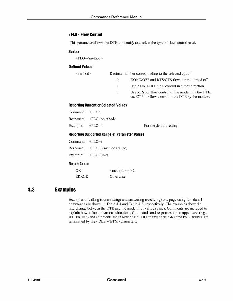
Commands Reference Manual
100498D Conexant 4-19
+FLO - Flow Control
This parameter allows the DTE to identify and select the type of flow control used.
Syntax
+FLO=<method>
Defined Values
<method> Decimal number corresponding to the selected option.
0 XON/XOFF and RTS/CTS flow control turned off.
1 Use XON/XOFF flow control in either direction.
2 Use RTS for flow control of the modem by the DTE;use CTS for flow control of the DTE by the modem.
Reporting Current or Selected Values
Command: +FLO?
Response: +FLO: <method>
Example: +FLO: 0 For the default setting.
Reporting Supported Range of Parameter Values
Command: +FLO=?
Response: +FLO: (<method>range)
Example: +FLO: (0-2)
Result Codes
OK <method> = 0-2.
ERROR Otherwise.
4.3 Examples
Examples of calling (transmitting) and answering (receiving) one page using fax class 1commands are shown in Table 4-4 and Table 4-5, respectively. The examples show theinterchange between the DTE and the modem for various cases. Comments are included toexplain how to handle various situations. Commands and responses are in upper case (e.g.,AT+FRH=3) and comments are in lower case. All streams of data denoted by <..frame> areterminated by the <DLE><ETX> characters.
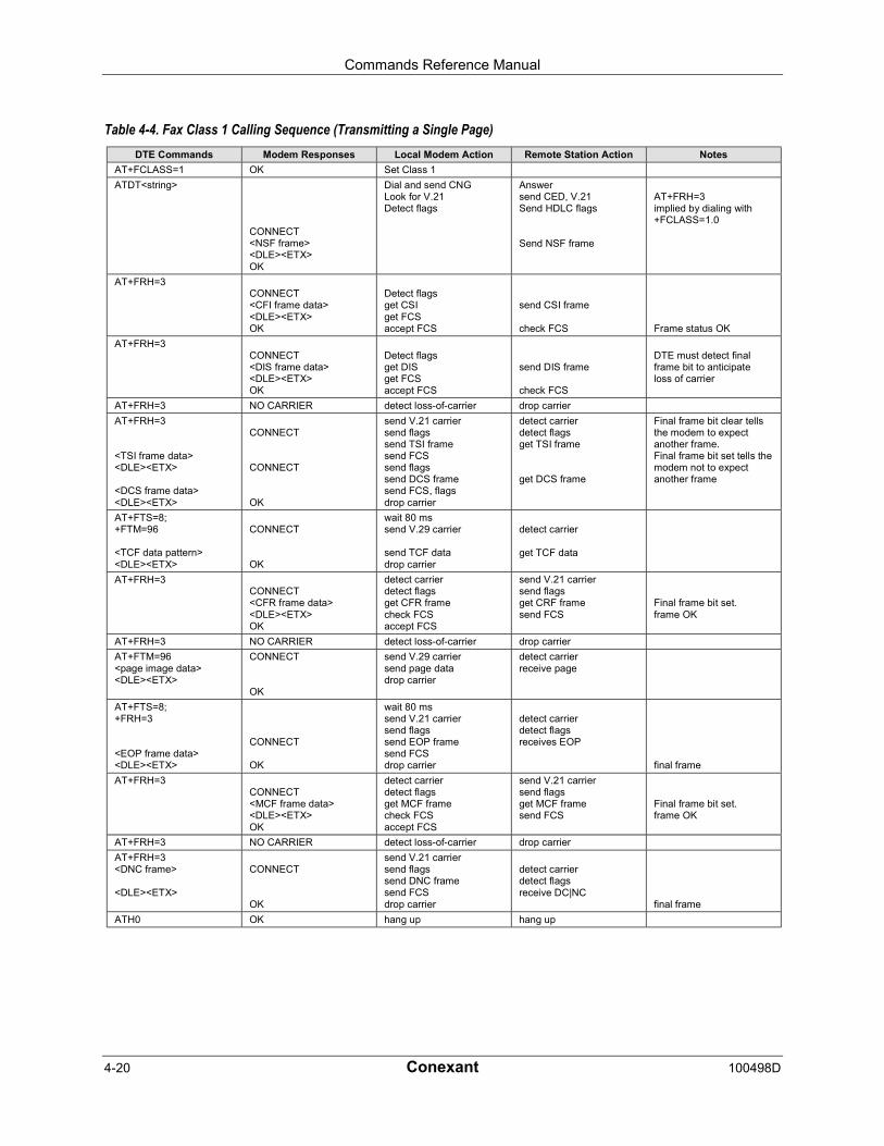
Commands Reference Manual
4-20 Conexant 100498D
Table 4-4. Fax Class 1 Calling Sequence (Transmitting a Single Page)DTE Commands Modem Responses Local Modem Action Remote Station Action Notes
AT+FCLASS=1 OK Set Class 1
ATDT<string>
CONNECT<NSF frame><DLE><ETX>OK
Dial and send CNGLook for V.21Detect flags
Answersend CED, V.21Send HDLC flags
Send NSF frame
AT+FRH=3implied by dialing with+FCLASS=1.0
AT+FRH=3CONNECT<CFI frame data><DLE><ETX>OK
Detect flagsget CSIget FCSaccept FCS
send CSI frame
check FCS Frame status OK
AT+FRH=3CONNECT<DIS frame data><DLE><ETX>OK
Detect flagsget DISget FCSaccept FCS
send DIS frame
check FCS
DTE must detect finalframe bit to anticipateloss of carrier
AT+FRH=3 NO CARRIER detect loss-of-carrier drop carrier
AT+FRH=3
<TSI frame data><DLE><ETX>
<DCS frame data><DLE><ETX>
CONNECT
CONNECT
OK
send V.21 carriersend flagssend TSI framesend FCSsend flagssend DCS framesend FCS, flagsdrop carrier
detect carrierdetect flagsget TSI frame
get DCS frame
Final frame bit clear tellsthe modem to expectanother frame.Final frame bit set tells themodem not to expectanother frame
AT+FTS=8;+FTM=96
<TCF data pattern><DLE><ETX>
CONNECT
OK
wait 80 mssend V.29 carrier
send TCF datadrop carrier
detect carrier
get TCF data
AT+FRH=3CONNECT<CFR frame data><DLE><ETX>OK
detect carrierdetect flagsget CFR framecheck FCSaccept FCS
send V.21 carriersend flagsget CRF framesend FCS
Final frame bit set.frame OK
AT+FRH=3 NO CARRIER detect loss-of-carrier drop carrier
AT+FTM=96<page image data><DLE><ETX>
CONNECT
OK
send V.29 carriersend page datadrop carrier
detect carrierreceive page
AT+FTS=8;+FRH=3
<EOP frame data><DLE><ETX>
CONNECT
OK
wait 80 mssend V.21 carriersend flagssend EOP framesend FCSdrop carrier
detect carrierdetect flagsreceives EOP
final frame
AT+FRH=3CONNECT<MCF frame data><DLE><ETX>OK
detect carrierdetect flagsget MCF framecheck FCSaccept FCS
send V.21 carriersend flagsget MCF framesend FCS
Final frame bit set.frame OK
AT+FRH=3 NO CARRIER detect loss-of-carrier drop carrier
AT+FRH=3<DNC frame>
<DLE><ETX>
CONNECT
OK
send V.21 carriersend flagssend DNC framesend FCSdrop carrier
detect carrierdetect flagsreceive DC|NC
final frame
ATH0 OK hang up hang up
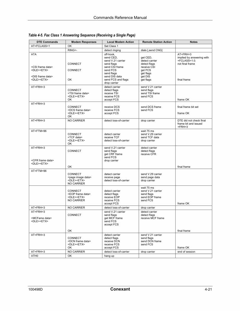
Commands Reference Manual
100498D Conexant 4-21
Table 4-5. Fax Class 1 Answering Sequence (Receiving a Single Page)DTE Commands Modem Responses Local Modem Action Remote Station Action Notes
AT+FCLASS=1 OK Set Class 1
RING<- detect ringing dials [,send CNG]
ATA
<CSI frame data><DLE><ETX>
<DIS frame data><DLE><ETX>
CONNECT
CONNECT
OK
off-hook,send CED,send V.21 carriersend flagssend CSI framesend FCSsend flagssend DIS datasend FCS and flagsdrop carrier
get CED,detect carrierdetect flagsreceive CSIget FCSget flagsget DISget flags
AT+FRH=3implied by answering with+FCLASS=1.0.not final frame
final frame
AT+FRH=3CONNECT<TSI frame data><DLE><ETX>OK
detect carrierdetect flagsreceive TSIreceive FCSaccept FCS
send V.21 carriersend flagssend TSI framesend FCS
frame OK
AT+FRH=3CONNECT<DCS frame data><DLE><ETX>OK
receive DCSreceive FCSaccept FCS
send DCS framesend FCS
final frame bit set
frame OK
AT+FRH=3 NO CARRIER detect loss-of-carrier drop carrier DTE did not check finalframe bit and issued+FRH=3
AT+FTM=96CONNECT<TCF data><DLE><ETX>OK
detect carrierreceive TCFdetect loss-of-carrier
wait 75 mssend V.29 carriersend TCF datadrop carrier
AT+FRH=3
<CFR frame data><DLE><ETX>
CONNECT
OK
send V.21 carriersend flagsget CRF framesend FCSdrop carrier
detect carrierdetect flagsreceive CFR
final frame
AT+FTM=96CONNECT<page image data><DLE><ETX>NO CARRIER
detect carrierreceive pagedetect loss-of-carrier
send V.29 carriersend page datadrop carrier
CONNECT<EOP frame data><DLE><ETX>NO CARRIER
detect carrierdetect flagsreceive EOPreceive FCSaccept FCS
wait 75 mssend V.21 carriersend flagssend EOP framesend FCS
frame OK
AT+FRH=3 NO CARRIER detect loss-of-carrier drop carrier
AT+FRH=3
<MCFame data><DLE><ETX>
CONNECT
OK
send V.21 carriersend flagsget MCF framesend FCSaccept FCS
detect carrierdetect flagsreceive MCF frame
final frame
AT+FRH=3CONNECT<DCN frame data><DLE><ETX>OK
detect carrierdetect flagsreceive DCNreceive FCSaccept FCS
send V.21 carriersend flagssend DCN framesend FCS
frame OK
AT+FRH=3 NO CARRIER detect loss-of-carrier drop carrier end of session
ATH0 OK hang up

Commands Reference Manual
4-22 Conexant 100498D
This page is intentionally blank.
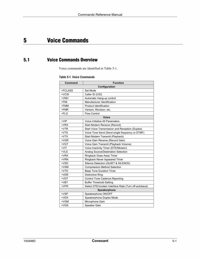
Commands Reference Manual
100498D Conexant 5-1
5 Voice Commands
5.1 Voice Commands Overview
Voice commands are identified in Table 5-1.
Table 5-1. Voice CommandsCommand Function
Configuration
+FCLASS Set Mode
+VCID Caller ID (CID)
+VNH Automatic Hang-up control
+FMI Manufacturer Identification
+FMM Product Identification
+FMR Version, Revision, etc.
+FLO Flow Control
Voice
+VIP Voice Initialize All Parameters
+VRX Start Modem Receive (Record)
+VTR Start Voice Transmission and Reception (Duplex)
+VTS Voice Tone Send (Send single frequency or DTMF)
+VTX Start Modem Transmit (Playback)
+VGR Voice Gain Receive (Record Gain)
+VGT Voice Gain Transmit (Playback Volume)
+VIT Voice Inactivity Timer (DTE/Modem)
+VLS Analog Source/Destination Selection
+VRA Ringback Goes Away Timer
+VRN Ringback Never Appeared Timer
+VSD Silence Detection (QUIET & SILENCE)
+VSM Compression Method Selection
+VTD Beep Tone Duration Timer
+VDR Distinctive Ring
+VDT Control Tone Cadence Reporting
+VBT Buffer Threshold Setting
+VPR Select DTE/modem Interface Rate (Turn off autobaud)
Speakerphone
+VSP Speakerphone ON/OFF
+VDX Speakerphone Duplex Mode
+VGM Microphone Gain
+VGS Speaker Gain
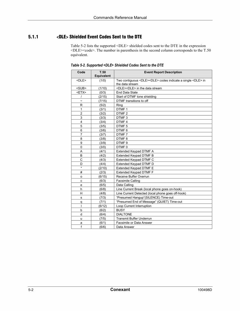
Commands Reference Manual
5-2 Conexant 100498D
5.1.1 <DLE> Shielded Event Codes Sent to the DTE
Table 5-2 lists the supported <DLE> shielded codes sent to the DTE in the expression<DLE><code>. The number in parenthesis in the second column corresponds to the T.50equivalent.
Table 5-2. Supported <DLE> Shielded Codes Sent to the DTECode T.50
EquivalentEvent Report Description
<DLE> (1/0) Two contiguous <DLE><DLE> codes indicate a single <DLE> inthe data stream
<SUB> (1/10) <DLE><DLE> in the data stream<ETX> (0/3) End Data State
/ (2/15) Start of DTMF tone shielding~ (7/15) DTMF transitions to offR (5/2) Ring1 (3/1) DTMF 12 (3/2) DTMF 23 (3/3) DTMF 34 (3/4) DTMF 45 (3/5) DTMF 56 (3/6) DTMF 67 (3/7) DTMF 78 (3/8) DTMF 89 (3/9) DTMF 90 (3/0) DTMF 0A (4/1) Extended Keypad DTMF AB (4/2) Extended Keypad DTMF BC (4/3) Extended Keypad DTMF CD (4/4) Extended Keypad DTMF D* (2/10) Extended Keypad DTMF E# (2/3) Extended Keypad DTMF Fo (6/15) Receive Buffer Overrunc (6/3) Facsimile Callinge (6/5) Data Callingh (6/8) Line Current Break (local phone goes on-hook)H (4/8) Line Current Detected (local phone goes off-hook)s (7/3) “Presumed Hangup”(SILENCE) Time-outq (7/1) “Presumed End of Message” (QUIET) Time-outl (6/12) Loop Current Interruptionb (6/2) BUSYd (6/4) DIALTONEu (7/5) Transmit Buffer Underruna (6/1) Facsimile or Data Answerf (6/6) Data Answer
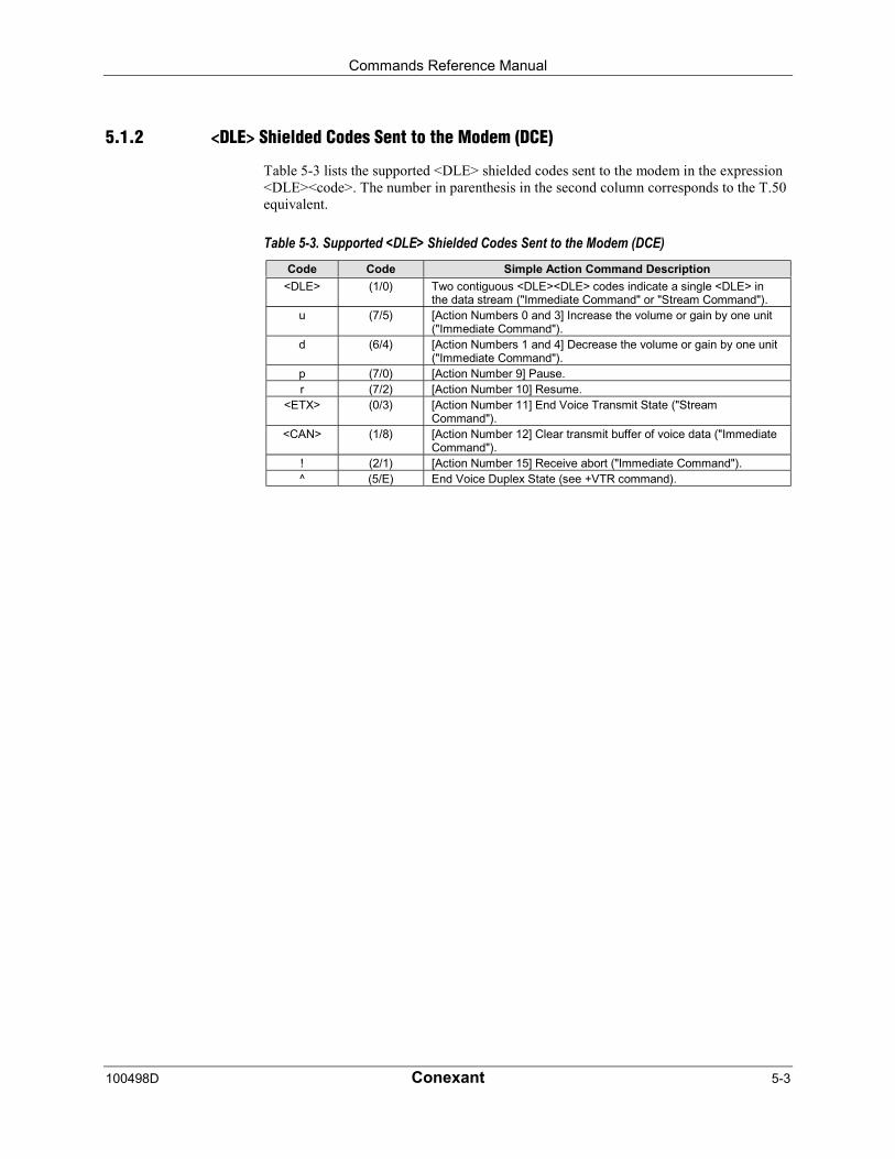
Commands Reference Manual
100498D Conexant 5-3
5.1.2 <DLE> Shielded Codes Sent to the Modem (DCE)
Table 5-3 lists the supported <DLE> shielded codes sent to the modem in the expression<DLE><code>. The number in parenthesis in the second column corresponds to the T.50equivalent.
Table 5-3. Supported <DLE> Shielded Codes Sent to the Modem (DCE)Code Code Simple Action Command Description
<DLE> (1/0) Two contiguous <DLE><DLE> codes indicate a single <DLE> inthe data stream ("Immediate Command" or "Stream Command").
u (7/5) [Action Numbers 0 and 3] Increase the volume or gain by one unit("Immediate Command").
d (6/4) [Action Numbers 1 and 4] Decrease the volume or gain by one unit("Immediate Command").
p (7/0) [Action Number 9] Pause.r (7/2) [Action Number 10] Resume.
<ETX> (0/3) [Action Number 11] End Voice Transmit State ("StreamCommand").
<CAN> (1/8) [Action Number 12] Clear transmit buffer of voice data ("ImmediateCommand").
! (2/1) [Action Number 15] Receive abort ("Immediate Command").^ (5/E) End Voice Duplex State (see +VTR command).
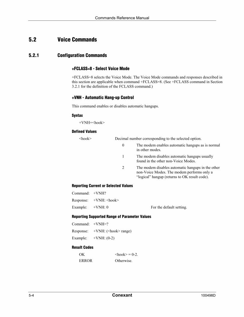
Commands Reference Manual
5-4 Conexant 100498D
5.2 Voice Commands
5.2.1 Configuration Commands
+FCLASS=8 - Select Voice Mode
+FCLASS=8 selects the Voice Mode. The Voice Mode commands and responses described inthis section are applicable when command +FCLASS=8. (See +FCLASS command in Section3.2.1 for the definition of the FCLASS command.)
+VNH - Automatic Hang-up Control
This command enables or disables automatic hangups.
Syntax
+VNH=<hook>
Defined Values
<hook> Decimal number corresponding to the selected option.
0 The modem enables automatic hangups as is normalin other modes.
1 The modem disables automatic hangups usuallyfound in the other non-Voice Modes.
2 The modem disables automatic hangups in the othernon-Voice Modes. The modem performs only a“logical” hangup (returns to OK result code).
Reporting Current or Selected Values
Command: +VNH?
Response: +VNH: <hook>
Example: +VNH: 0 For the default setting.
Reporting Supported Range of Parameter Values
Command: +VNH=?
Response: +VNH: (<hook> range)
Example: +VNH: (0-2)
Result Codes
OK <hook> = 0-2.
ERROR Otherwise.
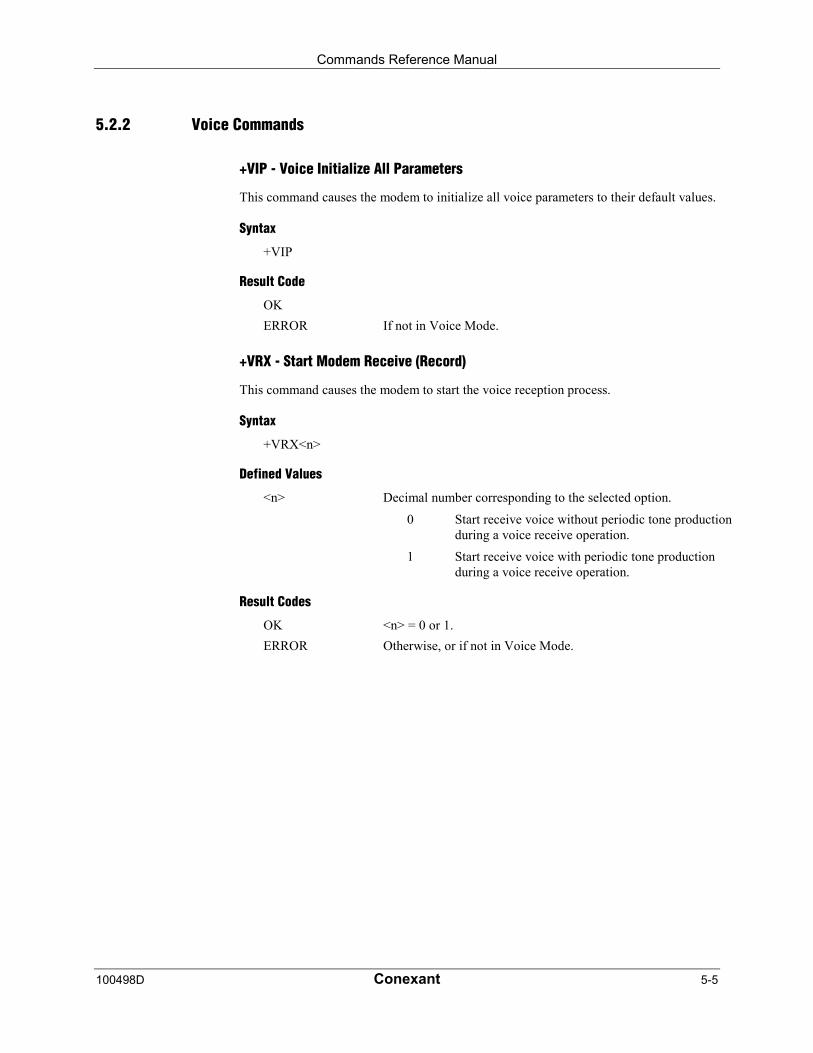
Commands Reference Manual
100498D Conexant 5-5
5.2.2 Voice Commands
+VIP - Voice Initialize All Parameters
This command causes the modem to initialize all voice parameters to their default values.
Syntax
+VIP
Result Code
OK
ERROR If not in Voice Mode.
+VRX - Start Modem Receive (Record)
This command causes the modem to start the voice reception process.
Syntax
+VRX<n>
Defined Values
<n> Decimal number corresponding to the selected option.
0 Start receive voice without periodic tone productionduring a voice receive operation.
1 Start receive voice with periodic tone productionduring a voice receive operation.
Result Codes
OK <n> = 0 or 1.
ERROR Otherwise, or if not in Voice Mode.

Commands Reference Manual
5-6 Conexant 100498D
+VTR - Start Voice Transmission and Reception (Voice Duplex)
This command causes the modem to start the voice transmission and reception process (VoiceDuplex) without either acoustic echo cancellation or line echo cancellation. The modembegins the Voice Duplex State by returning the CONNECT result code to the DTE. Themodem then sends <DLE> shielded voice data to the DTE, and the DTE can send <DLE>shielded voice data to the modem. The modem will accept data from the DTE and send datato the DTE in the format previously selected by the +VSM command, and use the flowcontrol method selected by the +IFC command.
The modem signals termination of the voice data stream by appending a <DLE><ETX>command and padding out to an octet boundary if needed. The modem will issue the<DLE><ETX> character pair (thereby ending the modem to DTE voice data flow) followedby the OK result code, and return to the command mode after the modem has completelytransmitted the contents of its buffer.
There are two methods to leave the Voice Duplex State: the DTE sending a <DLE><^>shielded code or the inactivity timer elapsing in the modem. The Voice Command State isentered upon Voice Duplex State termination.
This command will function when the input and output are from/to the same I/O device, suchas local handset, line, or mic/speaker.
Syntax
+VTR
Result Codes
OK Upon command acceptance.
ERROR The modem is not connected to the line and a non-line device.

Commands Reference Manual
100498D Conexant 5-7
+VTS - Send Voice Tone(s)
This command causes the modem to send DTMF digit or hookflash tones with the durationspecified by +VTD, to send DTMF digit or hookflash tones with duration specified by thiscommand, or to send single or dual tone frequencies with duration specified with thiscommand.
Syntax
+VTS=<string>
Defined Values
<string> The tone generation consists of elements in a list where eachelement is separated by a comma. Each element can be:
1. A single character which the modem interprets as a DTMFdigit (0 - 9, #, *, or A-D) or hookflash (!), with a durationgiven by the +VTD command.
2. A 3-element string enclosed in square brackets,"[freq1,freq2,dur]", which the modem interprets as a generaldual tone and duration selection, or
3. A 2-element string enclosed in curly braces, "{X,dur}", whichthe modem interprets as a DTMF digit (0 - 9, #, *, or A-D), orhookflash (!) with a duration (dur) different than that given bythe +VTD command,
Missing subparameters assume the default value. Unspecifiedvalues always default to zero for frequencies, DTMF * for DTMFtones, and +VTD for duration. The omission of commas (andassociated subparameters) are valid.
The quantity in the square brackets consists of a 3-element list(freq1,freq2,dur), which can be used to send single or dual tones.The first element is the first frequency (freq1) with range 0 or 200-3000 Hz. The second element is the second frequency (freq2), withrange 0 or 200-3000 Hz. The third element is the duration (dur) in0.01 second intervals with range 0-255 (ASCII units of 10 ms). Alist may contain null elements. For example [3000] means that theDCE generates a single tone at 3000 Hz for the default duration,[3000,3300] means that the DCE generates a dual tone at 3000 and3300 Hz for the default duration, and [,3300] means that the DCEgenerates a single tone at 3300 Hz for the default duration.
The quantity in the curly braces consists of a 2-element list(X,dur), which can be used to send DTMF tones or hookflash. Thefirst element is the DTMF tone or hookflash (!) character (X), andthe second element is the duration (dur) in 0.01 seconds. Thecharacters are of the same set given above. A list may contain nullelements. For example, {2} means DTMF tone "2" for the defaultduration, and {} means silence for the default duration.
The modem will stop the tone generation at the point in the stringwhere the modem detects a parsing error, encounters an invalidfrequency range, encounters a <CR>, or encounters a semi-colon.

Commands Reference Manual
5-8 Conexant 100498D
Reporting Supported Range of Parameter Values
Command: +VTS=?
Response: (<freq1> range), (<freq2> range), (<dur> range)
Example: (200-3000),(200-3000),(0-255)
Result Codes
OK Valid command.
ERROR The <string> command is invalid, or a selected frequency is out ofrange.
Example 1. This example illustrates tone generation without using any null elements. Thecommand example is followed by a description of command execution.
AT+VTS= {!,30},1,2,[1000,1300,50],!,{*,6},[800,1300,50],9
1. Hookflash with a duration of 300 ms.
2. Play DTMF 1 with a duration given by the +VTD command.
3. Play DTMF 2 with a duration given by the +VTD command.
4. Play tone pair at 1 000 Hz and 1 300 Hz with a duration of 500 ms.
5. Hookflash with a duration given by the +VTD command.
6. Play DTMF * with a duration of 60 ms.
7. Play tone pair at 800 Hz and 1300 Hz with a duration of 500 ms.
8. Play DTMF 9 with a duration given by the +VTD command.
Example 2. This example illustrates tone generation using null elements. The commandexample is followed by a description of command execution.
AT+VTS=1,2,[1000,1300,50],[800],9
1. Play DTMF 1 with a duration given by the +VTD command.
2. Play DTMF 2 with a duration given by the +VTD command.
3. Play tone pair at 1000 Hz and 1300 Hz with a duration of 500 ms.
4. Play tone pair at 800 Hz with a duration given by the +VTD command.
5. Play DTMF 9 with a duration given by the +VTD command.
Example 3. This example illustrates tone generation using null elements and periods ofsilence. The command example is followed by a description of command execution.
AT+VTS=1,[,,50],2,[],9
1. Play DTMF 1 with a duration given by the +VTD command.
2. Play silence with a duration of 500 ms.
3. Play DTMF 2 with a duration given by the +VTD command.
4. Play silence with a duration given by the +VTD command.
5. Play DTMF 9 with a duration given by the +VTD command.
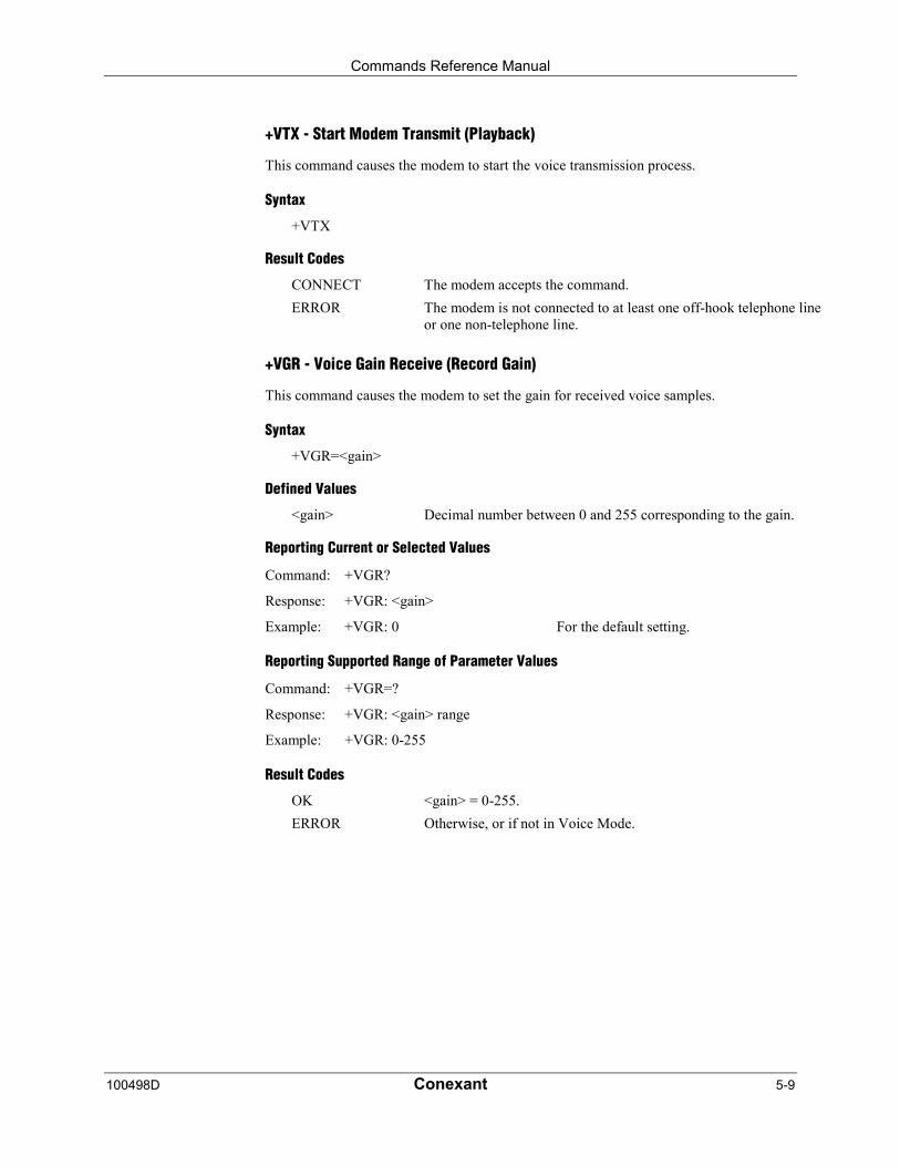
Commands Reference Manual
100498D Conexant 5-9
+VTX - Start Modem Transmit (Playback)
This command causes the modem to start the voice transmission process.
Syntax
+VTX
Result Codes
CONNECT The modem accepts the command.
ERROR The modem is not connected to at least one off-hook telephone lineor one non-telephone line.
+VGR - Voice Gain Receive (Record Gain)
This command causes the modem to set the gain for received voice samples.
Syntax
+VGR=<gain>
Defined Values
<gain> Decimal number between 0 and 255 corresponding to the gain.
Reporting Current or Selected Values
Command: +VGR?
Response: +VGR: <gain>
Example: +VGR: 0 For the default setting.
Reporting Supported Range of Parameter Values
Command: +VGR=?
Response: +VGR: <gain> range
Example: +VGR: 0-255
Result Codes
OK <gain> = 0-255.
ERROR Otherwise, or if not in Voice Mode.

Commands Reference Manual
5-10 Conexant 100498D
+VGT - Voice Gain Transmit (Playback Volume)
This command causes the modem to set the volume level.
Syntax
+VGT=<level>
Defined Values
<level> Decimal number (120-135) corresponding to the volume level.
Reporting Current or Selected Values
Command: +VGT?
Response: +VGT: <level>
Example: +VGT: 128 For the default setting.
Reporting Supported Range of Parameter Values
Command: +VGT=?
Response: +VGT: <level> range
Example: +VGT: 120-135
Result Codes
OK <level> = 120-135.
ERROR Otherwise, or if not in Voice Mode.
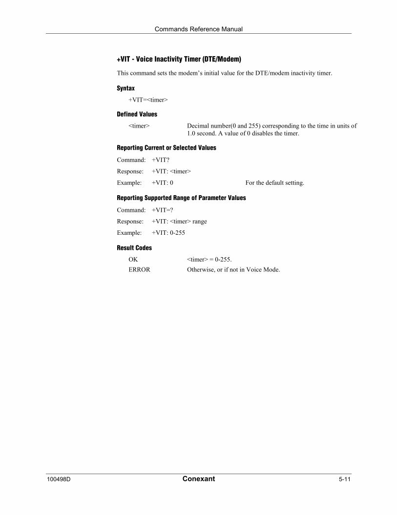
Commands Reference Manual
100498D Conexant 5-11
+VIT - Voice Inactivity Timer (DTE/Modem)
This command sets the modem’s initial value for the DTE/modem inactivity timer.
Syntax
+VIT=<timer>
Defined Values
<timer> Decimal number(0 and 255) corresponding to the time in units of1.0 second. A value of 0 disables the timer.
Reporting Current or Selected Values
Command: +VIT?
Response: +VIT: <timer>
Example: +VIT: 0 For the default setting.
Reporting Supported Range of Parameter Values
Command: +VIT=?
Response: +VIT: <timer> range
Example: +VIT: 0-255
Result Codes
OK <timer> = 0-255.
ERROR Otherwise, or if not in Voice Mode.

Commands Reference Manual
5-12 Conexant 100498D
+VLS - Analog Source/Destination Selection
This command causes the modem to select one or more source/destinations of the analog data.
Syntax
+VLS=<label>
Defined Values
<label> Decimal number corresponding to the selected option (see Table5-4).
Table 5-4. +VLS Command OptionsLabel Description
0 Modem on-hook. Local phone connected to the line.
1 Modem off-hook and connected to the line. Local phone provided with power to detect hook condition.
2 Modem on-hook and connected to the Local phone.
3 Modem off-hook and connected to the line and Local phone.
4 Internal Speaker connected to the Modem. Modem on-hook. Local phone connected to the line.
5 Internal Speaker connected to the line. Modem off-hook and connected to the line. Local phone provided withpower to detect hook condition.
6 Internal Microphone connected to the Modem. Modem on-hook. Local phone connected to the line.
7 Internal Microphone and Internal Speaker connected to the line. Squelching active. Modem off-hook andconnected to the line. Local phone provided with power to detect hook condition.
8 External Speaker connected to the Modem. Modem on-hook. Local phone connected to the line.
9 External Speaker connected to the line. Modem off-hook and connected to the line. Local phone provided withpower to detect hook condition.
10 Internal Microphone and External Speaker connected to the line. Squelching active. Modem off-hook andconnected to the line. Local phone provided with power to detect hook condition.
11 External Microphone connected to the Modem. Modem on-hook. Local phone connected to the line.
12 External Microphone and Internal Speaker connected to the line. Squelching active. Modem off-hook andconnected to the line. Local phone provided with power to detect hook condition.
13 External Microphone and External Speaker connected to the line. Squelching active. Modem off-hook andconnected to the line. Local phone provided with power to detect hook condition.
14 External Microphone and Speaker combination (handset or headset) connected to the Modem. Modem on-hook. Local phone connected to the line.
15 External Microphone and Speaker combination (handset or headset) connected to the line. Modem off-hookand connected to the line. Local phone provided with power to detect hook condition.
16 or 30 Mute Speakerphone Microphone.
17 or 31 Unmute Speakerphone Microphone.
18 or 32 Mute Speakerphone Speaker.
19 or 33 Unmute Speakerphone Speaker.
128 Modem on-hook, local phone connected to the line, external speaker connected to the modem. Caller ID relayoutput active.
129 Modem off-hook, local phone connected to the line, MIC_M routed to TXA. Typically used for music duringhandset conversation. Do not use this mode to answer incoming ring.
130 Modem off-hook, local phone disconnected from the line, MIC_M routed to TXA. Typically used to play greetingfrom audio codec.
131 Modem off-hook, local phone connected to the line, external speaker connected to the line. Typically used forrecording a handset conversation through a sound card.
Notes:
1. Internal and External Microphone are treated the same by the Modem device set.
2. Internal and External Speaker are treated the same by the Modem device set.

Commands Reference Manual
100498D Conexant 5-13
Reporting Current or Selected Values
Command: +VLS?
Response: +VLS: <label>
Example: +VLS: 0 For the default setting.
Reporting Supported Range of Parameter Values
Command: +VLS=?
Response: +VLS: <label> range
Example: +VLS: 0-19, 30-33, 128-131
Result Codes
OK <label> = 0-19, 30-33, 128-131.
ERROR Otherwise.
+VRA - Ringback Goes Away Timer
This command sets the length of time the modem will wait between ringbacks during callorigination before the modem can assume that the remote station has gone off hook.
Syntax
+VRA=<interval>
Defined Values
<interval> Decimal number (0-255) specifying the silence interval time inunits of 0.10 second between the end of one ring interval and thestart of the next ring interval. A value of 0 forces the modem toreport the OK result code immediately after the first Ringback. Therange is 0.01 to 60.0 seconds for <interval> = 1 to 255.
Reporting Current or Selected Values
Command: +VRA?
Response: +VRA: <interval>
Example: +VRA: 50 (0.5 seconds) For the default setting.
Reporting Supported Range of Parameter Values
Command: +VRA=?
Response: +VRA: (<interval> range)
Example: +VRA: (0-255)
Result Codes
OK <interval> = 0-255
ERROR Otherwise, or if not in Voice Mode.
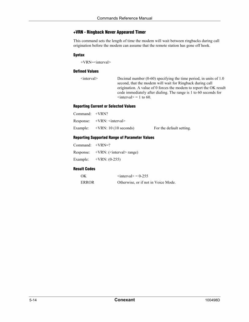
Commands Reference Manual
5-14 Conexant 100498D
+VRN - Ringback Never Appeared Timer
This command sets the length of time the modem will wait between ringbacks during callorigination before the modem can assume that the remote station has gone off hook.
Syntax
+VRN=<interval>
Defined Values
<interval> Decimal number (0-60) specifying the time period, in units of 1.0second, that the modem will wait for Ringback during callorigination. A value of 0 forces the modem to report the OK resultcode immediately after dialing. The range is 1 to 60 seconds for<interval> = 1 to 60.
Reporting Current or Selected Values
Command: +VRN?
Response: +VRN: <interval>
Example: +VRN: 10 (10 seconds) For the default setting.
Reporting Supported Range of Parameter Values
Command: +VRN=?
Response: +VRN: (<interval> range)
Example: +VRN: (0-255)
Result Codes
OK <interval> = 0-255
ERROR Otherwise, or if not in Voice Mode.

Commands Reference Manual
100498D Conexant 5-15
+VSD - Silence Detection (Quiet and Silence)
This command causes the modem to set the silence detection sensitivity and the requiredperiod of silence before the modem reports silence detected at the end of a voice receiveeither with the “Presumed End of Message” (QUIT) or “Presumed Hangup (SILENCE) eventreports.
Syntax
+VSD=<sds>,<sdi>
Defined Values
<sds> Decimal number corresponding to the selected parameter.
0 Use +VSM silence compression setting andalgorithm for long-term silence detection (if +VSM isin use) or proprietary silence compression setting andalgorithm for long-term silence detection (if +VSM isnot in use).
127 Sets less aggressive long-term silence detectionindependent of presence or use of silencecompression.
128 Sets nominal long-term silence detection independentof presence or use of silence compression.
129 Sets more aggressive long-term silence detectionindependent of presence or use of silencecompression.
<sdi> Decimal number specifying the required period of silence, in unitsof 0.1 second, before the modem can report silence detected at theend of a voice receive either with the “Presumed End of Message”(QUIT) or “Presumed Hangup (SILENCE) event reports. A valueof 0 disables the modem silence detection. The range is 0.1 to 25.5seconds for <sdi> = 1 to 255.
Reporting Current or Selected Values
Command: +VSD?
Response: +VSD: <sds>,<sdi>
Example: +VSD: 128, 50 For the default setting.
Reporting Supported Range of Parameter Values
Command: +VSD=?
Response: +VSD: (<sds> range),(<sdi> range)
Example: +VSD: (0,127,128,129),(0-255)
Result Codes
OK <hook> = 0 or 1.
ERROR Otherwise, or if not in Voice Mode.

Commands Reference Manual
5-16 Conexant 100498D
+VSM - Compression Method Selection
This command causes the modem to set the voice compression method, the silencecompression sensitivity, and the voice sampling rate.
Syntax
+VSM=<cml>,<vsr>,<sds>,<sel>
Defined Values
<cml> Decimal number identifying the compression method.
<vsr> <range of values> containing the supported range of voice samplesper second of the analog signal.
<scs> <range of values> containing the supported range of sensitivitysettings for voice receives.
<sel> <range of values> containing the supported range of expansionvalues for voice transmits.
Reporting Current or Selected Values
Command: +VSM?
Response: +VSM: <cml>,<vsr>,<sds>, <sel>
Example: +VSM: 130,UNSIGNED PCM,8,0,127,0
Reporting Supported Range of Parameter Values
Command: +VSM=?
Response: +VSM: <cml>, <cmid>, <bps>, <tm>,<vsr>,<sds>, <sel>
<cml> Decimal number identifying the compression method (1, 128 to133).
<cmid> Alphanumeric string describing the compression method(UNSIGNED PCM, 8-BIT LINEAR, ADPCM, ULAW, ALAW,or LINEAR).
<bps> Decimal number defining the average number of bits in thecompressed sample not including silence compression (4, 8, or 16).
<tm> Decimal number (0) reporting the time interval, in units of 0.1second, between timing marks. A value of 0 reports that timingmarks are not supported.
<vsr> <range of values> containing the supported range of voice samplesper second of the analog signal (7200 or 8000).
<scs> <range of values> containing the supported range of sensitivitysettings for voice receives (0).
<sel> <range of values> containing the supported range of expansionvalues for voice transmits (0).
Commands Reference Manual
100498D Conexant 5-17
Example:
AT+VSM=?
1,"UNSIGNED PCM",8,0,(7200,8000),(0),(0)128,"8-BIT LINEAR",8,0,(7200,8000),(0),(0)129,"ADPCM",4,0,(7200,8000),(0),(0)130,"UNSIGNED PCM",8,0,(7200,8000),(0),(0)131,"ULAW",8,0,(7200,8000),(0),(0)132,"ALAW",8,0,(7200,8000),(0),(0)133,"LINEAR",16,0,(7200,8000),(0),(0)
Result Codes
OK Valid range.
ERROR Otherwise, or if not in Voice Mode.
+VTD - Beep Tone Duration Timer
This command causes the modem to set the default DTMF/tone generation duration.
Syntax
+VTD=<dur>
Defined Values
<dur> Decimal number specifying the default DTMF/tone generationduration in units of 0.01 second. A value of 0 specifies amanufacturer specific time interval. The range is 0.01 to 5 secondsfor <dur> = 1 to 500.
Reporting Current or Selected Values
Command: +VTD?
Response: +VTD: <dur>
Example: +VTD: 0 For the default setting.
Reporting Supported Range of Parameter Values
Command: +VTD=?
Response: +VTD: (<dur> range)
Example: +VTD: (0-500)
Result Codes
OK <dur>= 0-500.
ERROR Otherwise, or if not in Voice Mode.
Commands Reference Manual
5-18 Conexant 100498D
+VDR - Distinctive Ring
This command causes the modem to enable or disable reporting of the ring cadenceinformation and to control the timing of the RING event code report if ring cadence reportingis enabled.
Syntax
+VDR=<enable>, <report>
Defined Values
<enable> Decimal number corresponding to the selected option.
0 The modem will not report ring cadence information.
1 The modem will report ring cadence information asspecified for the <report> subparameter.
<report> Decimal number specifying ring cadence information report whenenabled by the <enable> subparameter.
0 The modem will produce only DROF and DRONmessages. The modem will not produce any RINGevent codes. The modem will report other callprogress event codes as normal.
Other The modem will produce only DROF and DRONmessages. The modem will produce a RING eventcode after <report>/10 seconds after the falling edgeof the ring pulse (i.e., after the DRON report).
Reporting Current or Selected Values
Command: +VDR?
Response: +VDR: <enable>,<report>
Example: +VDR: 0,0 For the default setting.
Reporting Supported Range of Parameter Values
Command: +VDR=?
Response: +VDR: (<enable> range),(<report>range)
Example: +VDR: (0,1),(0-60)
Result Codes
OK <enable>,<report> = (0,1),(0-60)
ERROR Otherwise, or if not in Voice Mode.
Commands Reference Manual
100498D Conexant 5-19
+VDT - Control Tone Cadence Reporting
This command allows the modem to enable or disable reporting of the control tone cadenceinformation in the frequency band used by the Ringback/Remote Ring, BUSY, andreorder/Fast Busy tones (usually in the 300to 600 Hz range).
Syntax
+VDT=<enable>,<report>
Defined Values
<enable> Decimal number corresponding to the selected option.
0 The modem will not produce any control tonecadence report.
1 The modem will produce control tone cadence reportas specified for the <report> subparameter.
<report> Decimal number specifying the produced any control tone cadencereport when enabled by the <enable> subparameter.
0 The modem will produce only CPOF and CPONmessages.
Other Reserved.
Reporting Current or Selected Values
Command: +VDT?
Response: +VDT: <enable>,<report>
Example: +VDT: 0,0 For the default setting.
Reporting Supported Range of Parameter Values
Command: +VDT=?
Response: +VDT: (<enable> range),(<report> range)
Example: +VDT: (0,1),(0)
Result Codes
OK <enable>,<report> = (0,1),(0)
ERROR Otherwise, or if not in Voice Mode.
Commands Reference Manual
5-20 Conexant 100498D
+VBT - Buffer Threshold Setting
This command causes the modem to report the <deassert> and <assert> subparameter valuesas a <compound ranges of values>. The OK result code follows the report.
Syntax
+VBT=<deassert>,<assert>
Defined Values
To be added
Reporting Current or Selected Values
Command: +VBT?
Response: +VBT: <deassert>,<assert>
Example: +VBT: TBD For the default setting.
Reporting Supported Range of Parameter Values
Command: +VBT=?
Response: +VBT: (<deassert> range), (assert>range)
Example: +VBT: (820-4096),(6144-7372), 8192
Result Codes
OK <deassert>,<assert>= 0 or 1.
ERROR Otherwise, or if not in Voice Mode.
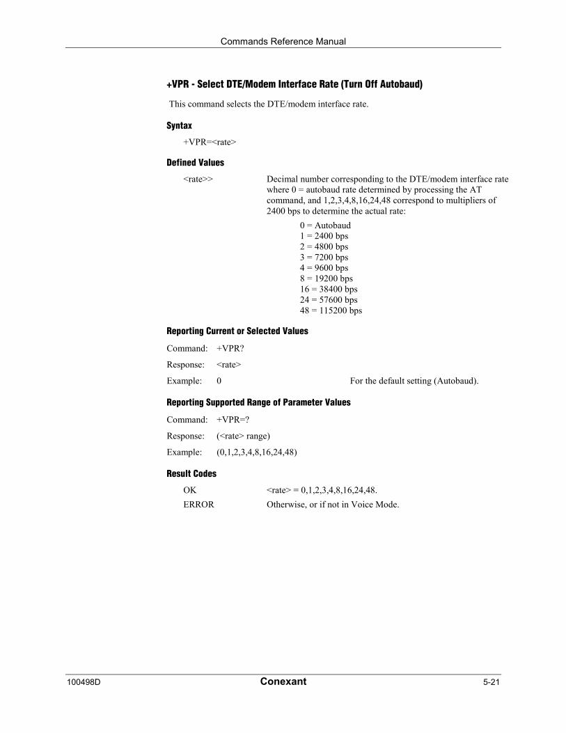
Commands Reference Manual
100498D Conexant 5-21
+VPR - Select DTE/Modem Interface Rate (Turn Off Autobaud)
This command selects the DTE/modem interface rate.
Syntax
+VPR=<rate>
Defined Values
<rate>> Decimal number corresponding to the DTE/modem interface ratewhere 0 = autobaud rate determined by processing the ATcommand, and 1,2,3,4,8,16,24,48 correspond to multipliers of2400 bps to determine the actual rate:
0 = Autobaud1 = 2400 bps2 = 4800 bps3 = 7200 bps4 = 9600 bps8 = 19200 bps16 = 38400 bps24 = 57600 bps48 = 115200 bps
Reporting Current or Selected Values
Command: +VPR?
Response: <rate>
Example: 0 For the default setting (Autobaud).
Reporting Supported Range of Parameter Values
Command: +VPR=?
Response: (<rate> range)
Example: (0,1,2,3,4,8,16,24,48)
Result Codes
OK <rate> = 0,1,2,3,4,8,16,24,48.
ERROR Otherwise, or if not in Voice Mode.
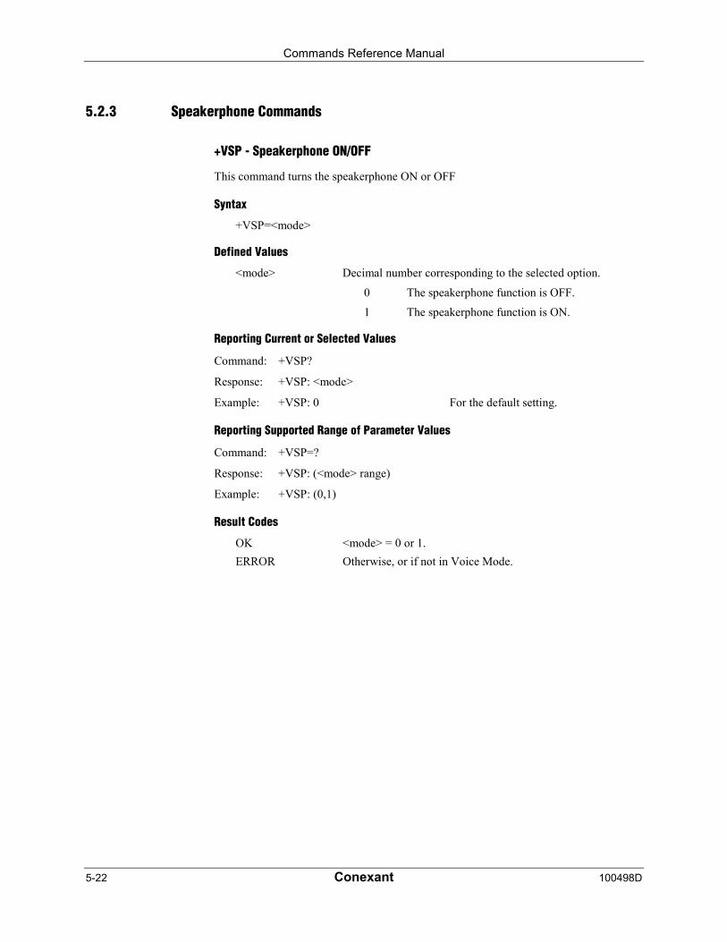
Commands Reference Manual
5-22 Conexant 100498D
5.2.3 Speakerphone Commands
+VSP - Speakerphone ON/OFF
This command turns the speakerphone ON or OFF
Syntax
+VSP=<mode>
Defined Values
<mode> Decimal number corresponding to the selected option.
0 The speakerphone function is OFF.
1 The speakerphone function is ON.
Reporting Current or Selected Values
Command: +VSP?
Response: +VSP: <mode>
Example: +VSP: 0 For the default setting.
Reporting Supported Range of Parameter Values
Command: +VSP=?
Response: +VSP: (<mode> range)
Example: +VSP: (0,1)
Result Codes
OK <mode> = 0 or 1.
ERROR Otherwise, or if not in Voice Mode.
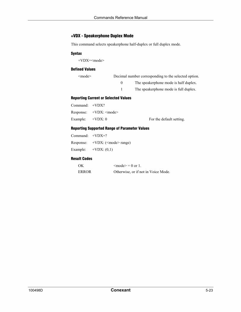
Commands Reference Manual
100498D Conexant 5-23
+VDX - Speakerphone Duplex Mode
This command selects speakerphone half-duplex or full duplex mode.
Syntax
+VDX=<mode>
Defined Values
<mode> Decimal number corresponding to the selected option.
0 The speakerphone mode is half duplex.
1 The speakerphone mode is full duplex.
Reporting Current or Selected Values
Command: +VDX?
Response: +VDX: <mode>
Example: +VDX: 0 For the default setting.
Reporting Supported Range of Parameter Values
Command: +VDX=?
Response: +VDX: (<mode> range)
Example: +VDX: (0,1)
Result Codes
OK <mode> = 0 or 1.
ERROR Otherwise, or if not in Voice Mode.

Commands Reference Manual
5-24 Conexant 100498D
+VGM - Microphone Gain
This command causes the modem to set the microphone gain of the speakerphone function.
Syntax
+VGM=<gain>
Defined Values
<gain> Decimal number between 0 and 255 corresponding to the gain.
Reporting Current or Selected Values
Command: +VGM?
Response: +VGM: <gain>
Example: +VGM: 130 For the default setting.
Reporting Supported Range of Parameter Values
Command: +VGM=?
Response: +VGM: <gain> range
Example: +VGM: 0-255
Result Codes
OK <gain> = 0-255.
ERROR Otherwise, or if not in Voice Mode with speakerphone enabled(+VSP=1).
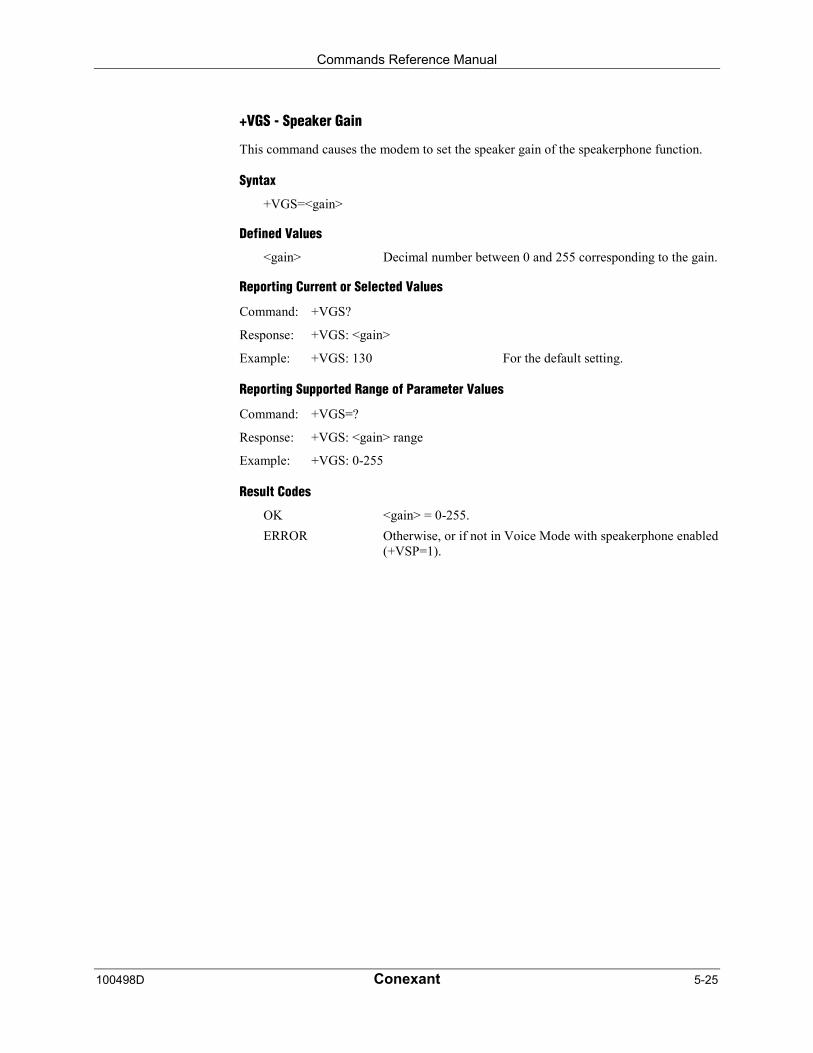
Commands Reference Manual
100498D Conexant 5-25
+VGS - Speaker Gain
This command causes the modem to set the speaker gain of the speakerphone function.
Syntax
+VGS=<gain>
Defined Values
<gain> Decimal number between 0 and 255 corresponding to the gain.
Reporting Current or Selected Values
Command: +VGS?
Response: +VGS: <gain>
Example: +VGS: 130 For the default setting.
Reporting Supported Range of Parameter Values
Command: +VGS=?
Response: +VGS: <gain> range
Example: +VGS: 0-255
Result Codes
OK <gain> = 0-255.
ERROR Otherwise, or if not in Voice Mode with speakerphone enabled(+VSP=1).

Commands Reference Manual
5-26 Conexant 100498D
This page is intentionally blank.

Commands Reference Manual
100498D Conexant 6-1
6 Index
#
#UD – Last Call Status Report ....................................... 3-59
%
%C - Enable/Disable Data Compression........................ 3-48%E - Enable/Disable Line Quality Monitor, Auto-Retrain, and
Auto-Rate Renegotiation .................................... 3-37%TT - PTT Test Command ............................................ 3-66
&
&C - RLSD Behavior ...................................................... 3-18&D - DTR Behavior ........................................................ 3-19&F - Set to Factory-Defined Configuration........................ 3-6&G - Select Guard Tone................................................. 3-30&K - Flow Control........................................................... 3-20&M - Asynchronous/Synchronous Mode Selection ......... 3-20&P - Select Pulse Dial Make/Break Ratio ....................... 3-30&Q - Sync/Async Mode .................................................. 3-21&T - Local Analog Loopback Test .................................... 3-6&V - Display Current Configuration and Stored Profiles.. 3-31&W - Store Current Configuration................................... 3-31
*
*B - Display Blacklisted Numbers ................................... 3-32*D - Display Delayed Numbers....................................... 3-32
+
+A8A - Answer Signal Indication .................................... 3-52+A8C - Calling Tone Indication....................................... 3-51+A8E - V.8 and V.8bis Operation Controls ..................... 3-49+A8I - CI Signal Indication.............................................. 3-51+A8J - V.8 Negotiation Complete ................................... 3-52+A8M - V.8 Menu Report ............................................... 3-53+A8M - Send V.8 Menu Signals ..................................... 3-50+A8R - V.8bis Signal and Message Reporting................ 3-53+DR - Data Compression Reporting............................... 3-47+DS - Data Compression ............................................... 3-45+DS44 - V.44 Compression Select................................. 3-46+EB - Break Handling in Error Control Operation ........... 3-40+EFCS - 32-bit Frame Check Sequence ........................ 3-41+ER - Error Control Reporting ........................................ 3-42+ES - Error Control and Synchronous Mode Selection... 3-38+ESA - Configure Synchronous Access Mode ............... 3-56+ESR - Selective Repeat ............................................... 3-40+ETBM - Call Termination Buffer Management .............. 3-44+FAE - Auto Answer Enable............................................. 4-6+FAR - Adaptive Reception Control ............................... 4-13+FCL - Carrier Loss Timeout.......................................... 4-14+FCLASS- Select Active Service Class............................ 3-2+FCLASS=1 - Select Facsimile Class 1 Mode.................. 4-6+FCLASS=1.0 - Select Facsimile Class 1.0 Mode............ 4-6+FCLASS=8 - Select Voice Mode .................................... 5-4+FDD - Double Escape Character Replacement ............ 4-15+FIT - DTE Inactivity Timeout......................................... 4-16+FLO - Flow Control....................................................... 4-19+FMI - Request Manufacturer Identification.................... 4-18+FMM - Request Model Identification............................. 4-18
+FMR - Request Revision Identification..........................4-18+FPR - Fixed DTE Rate..................................................4-17+FRH - Receive Data with HDLC Framing......................4-12+FRM - Receive Data .....................................................4-10+FRS - Receive Silence ...................................................4-8+FTH - Transmit Data with HDLC Framing .....................4-11+FTM - Transmit Facsimile ...............................................4-9+FTS - Transmit Silence...................................................4-7+GCAP - Request Complete Capabilities List .................3-10+GCI - Country of Installation .........................................3-11+GMI - Request Manufacturer Identification......................3-8+GMM - Request Model Identification...............................3-9+GMR - Request Revision Identification ...........................3-9+GOI - Request Global Object Identification ...................3-10+GSN - Request Product Serial Number Identification......3-9+IFC - DTE-Modem Local Flow Control ..........................3-23+ILRR - DTE-Modem Local Rate Reporting....................3-24+IPR - Fixed DTE Rate...................................................3-22+ITF - Transmit Flow Control Thresholds........................3-58+MR - Modulation Reporting Control...............................3-36+MS - Modulation Selection............................................3-33+PCW - Call Waiting Enable...........................................3-69+PIG - PCM Upstream Ignore.........................................3-73+PMH - Modem-on-Hold Enable.....................................3-70+PMHF - V.92 Modem-on-Hold Hook Flash....................3-73+PMHR - Initiate Modem-on-Hold...................................3-72+PMHT – Modem-on-Hold Timer....................................3-71+PQC - V.92 Phase 1 and Phase 2 Control ....................3-74+PSS - Use Short Sequence ..........................................3-75+VBT - Buffer Threshold Setting .....................................5-20+VCID - Caller ID (CID) ....................................................3-3+VDR - Distinctive Ring ..................................................5-18+VDT - Control Tone Cadence Reporting .......................5-19+VDX - Speakerphone Duplex Mode ..............................5-23+VGM - Microphone Gain...............................................5-24+VGR - Voice Gain Receive (Record Gain) ......................5-9+VGS - Speaker Gain.....................................................5-25+VGT - Voice Gain Transmit (Playback Volume) ............5-10+VIP - Voice Initialize All Parameters................................5-5+VIT - Voice Inactivity Timer (DTE/Modem.....................5-11+VNH - Automatic Hang-up Control ..................................5-4+VPR - Select DTE/Modem Interface Rate)....................5-21+VRA - Ringback Goes Away Timer ...............................5-13+VRID - Caller ID (CID) ....................................................3-4+VRN - Ringback Never Appeared Timer .......................5-14+VRX - Start Modem Receive (Record) ............................5-5+VSD - Silence Detection (Quiet and Silence .................5-15+VSM - Compression Method Selection .........................5-16+VSP - Speakerphone ON/OFF......................................5-22+VTD - Beep Tone Duration Timer .................................5-17+VTR - Start Voice Transmission and Reception (Voice
Duplex) .................................................................5-6+VTS - Send Voice Tone(s)..............................................5-7+VTX - Start Modem Transmit (Playback..........................5-9+WS= – Enable/Disable PDC .........................................3-83
A
A - Answer......................................................................3-27AT? - Read Selected S-Parameter .................................3-77AT=x - Write to Selected S-Parameter............................3-77
Commands Reference Manual
6-2 Conexant 100498D
D
D - Dial3-25
E
E - Command Echo........................................................ 3-12
H
H - Disconnect (Hang-Up) .............................................. 3-28
I
I - Request Identification Information................................ 3-7
L
L - Speaker Volume ....................................................... 3-29
M
M - Speaker Control ....................................................... 3-29
N
N - Automode Enable..................................................... 3-49\N - Operating Mode......................................................... 3-5
O
O - Return to On-Line Data Mode .................................. 3-28
P
P - Set Pulse Dial Default............................................... 3-27
Q
Q - Quiet Results Codes Control .................................... 3-12-QCPC - Force Full Startup Procedure Next Connection 3-76-QCPS - Enable Quick Connect Profile Save ................. 3-76
S
S0 - Number of Rings to Automatic Answer ....................3-78S1 - Ring Counter...........................................................3-78S10 - Lost Carrier To Hang Up Delay .............................3-81S11 - DTMF Tone Duration ............................................3-81S12 - Escape Prompt Delay (EPD) .................................3-81S18 - Test Timer.............................................................3-81S2 - Escape Character ...................................................3-79S29 - Flash Dial Modifier Time........................................3-81S3 - Line Termination Character.....................................3-79S30 - Disconnect Inactivity Timer....................................3-82S4 - Response Formatting Character .............................3-79S46 - Data Compression Control ....................................3-82S5 - Command Line Editing Character............................3-79S6 - Wait Time for Dial Tone Before Blind Dialing, or After
“W” Dial Modifier.................................................3-80S7 - Wait Time For Carrier After Dial, For Silence, or For Dial
Tone After “W” Dial Modifier ...............................3-80S8 - Pause Time For Dial Delay .....................................3-80S95 - Extended Result Codes Control ............................3-82Sn - Read/Write S-Parameter .........................................3-78
T
T - Set Tone Dial Default ................................................3-27
V
V - Result Code Form.....................................................3-13
W
W - Connect Message Control........................................3-13
X
X - Extended Result Codes ............................................3-14
Z
Z - Reset to Default Configuration.....................................3-2

NOTES

Further [email protected](800) 854-8099 (North America)(949) 483-6996 (International)Printed in USA
World HeadquartersConexant Systems, Inc.4311 Jamboree RoadNewport Beach, CA92660-3007Phone: (949) 483-4600Fax 1: (949) 483-4078Fax 2: (949) 483-4391
Americas
U.S. Northwest/Pacific Northwest – Santa ClaraPhone: (408) 249-9696Fax: (408) 249-7113
U.S. Southwest – Los AngelesPhone: (805) 376-0559Fax: (805) 376-8180
U.S. Southwest – Orange CountyPhone: (949) 483-9119Fax: (949) 483-9090
U.S. Southwest – San DiegoPhone: (858) 713-3374Fax: (858) 713-4001
U.S. North Central – IllinoisPhone: (630) 773-3454Fax: (630) 773-3907
U.S. South Central – TexasPhone: (972) 733-0723Fax: (972) 407-0639
U.S. Northeast – MassachusettsPhone: (978) 367-3200Fax: (978) 256-6868
U.S. Southeast – North CarolinaPhone: (919) 858-9110Fax: (919) 858-8669
U.S. Southeast – Florida/South AmericaPhone: (727) 799-8406Fax: (727) 799-8306
U.S. Mid-Atlantic – PennsylvaniaPhone: (215) 244-6784Fax: (215) 244-9292
Canada – OntarioPhone: (613) 271-2358Fax: (613) 271-2359
Europe
Europe Central – GermanyPhone: +49 89 829-1320Fax: +49 89 834-2734
Europe North – EnglandPhone: +44 1344 486444Fax: +44 1344 486555
Europe – Israel/GreecePhone: +972 9 9524000Fax: +972 9 9573732
Europe South – FrancePhone: +33 1 41 44 36 51Fax: +33 1 41 44 36 90
Europe Mediterranean – ItalyPhone: +39 02 93179911Fax: +39 02 93179913
Europe – SwedenPhone: +46 (0) 8 5091 4319Fax: +46 (0) 8 590 041 10
Europe – FinlandPhone: +358 (0) 9 85 666 435Fax: +358 (0) 9 85 666 220
Asia – Pacific
TaiwanPhone: (886-2) 2-720-0282Fax: (886-2) 2-757-6760
AustraliaPhone: (61-2) 9869 4088Fax: (61-2) 9869 4077
China – CentralPhone: 86-21-6361-2515Fax: 86-21-6361-2516
China – SouthPhone: (852) 2 827-0181Fax: (852) 2 827-6488
China – South (Satellite)Phone: (86) 755-5182495
China – NorthPhone: (86-10) 8529-9777Fax: (86-10) 8529-9778
IndiaPhone: (91-11) 692-4789Fax: (91-11) 692-4712
KoreaPhone: (82-2) 565-2880Fax: (82-2) 565-1440
Korea (Satellite)Phone: (82-53) 745-2880Fax: (82-53) 745-1440
SingaporePhone: (65) 737 7355Fax: (65) 737 9077
JapanPhone: (81-3) 5371 1520Fax: (81-3) 5371 1501
www.conexant.com
0.0 Sales Offices