Embed Size (px)
Citation preview
Commercial Air-CooledCondensing Units 50Hz
50 to
180 N
om
inal T
on
s
(175 to
633 N
om
inal K
W)
Certificate No.: 9190.C308
FORM SSI - 38XD (1400)
38XD050-180
INTRODUCTION
1
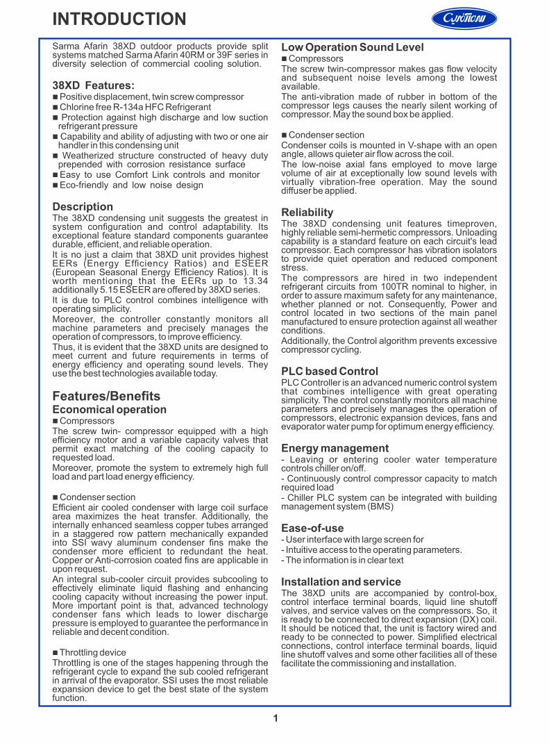
Sarma Afarin 38XD outdoor products provide split systems matched Sarma Afarin 40RM or 39F series in diversity selection of commercial cooling solution.
38XD Features:n Positive displacement, twin screw compressorn Chlorine free R-134a HFC Refrigerantn Protection against high discharge and low suction
refrigerant pressuren Capability and ability of adjusting with two or one air
handler in this condensing unitn Weatherized structure constructed of heavy duty
prepended with corrosion resistance surfacen Easy to use Comfort Link controls and monitorn Eco-friendly and low noise design
DescriptionThe 38XD condensing unit suggests the greatest in system configuration and control adaptability. Its exceptional feature standard components guarantee durable, efficient, and reliable operation.It is no just a claim that 38XD unit provides highest EERs (Energy Efficiency Ratios) and ESEER (European Seasonal Energy Efficiency Ratios). It is worth mentioning that the EERs up to 13.34 additionally 5.15 ESEER are offered by 38XD series.It is due to PLC control combines intelligence with operating simplicity.Moreover, the controller constantly monitors all machine parameters and precisely manages the operation of compressors, to improve efficiency.Thus, it is evident that the 38XD units are designed to meet current and future requirements in terms of energy efficiency and operating sound levels. They use the best technologies available today.
Features/BenefitsEconomical operationn CompressorsThe screw twin- compressor equipped with a high efficiency motor and a variable capacity valves that permit exact matching of the cooling capacity to requested load.Moreover, promote the system to extremely high full load and part load energy efficiency.
n Condenser sectionEfficient air cooled condenser with large coil surface area maximizes the heat transfer. Additionally, the internally enhanced seamless copper tubes arranged in a staggered row pattern mechanically expanded into SSI wavy aluminum condenser fins make the condenser more efficient to redundant the heat. Copper or Anti-corrosion coated fins are applicable in upon request.An integral sub-cooler circuit provides subcooling to effectively eliminate liquid flashing and enhancing cooling capacity without increasing the power input. More important point is that, advanced technology condenser fans which leads to lower discharge pressure is employed to guarantee the performance in reliable and decent condition.
n Throttling deviceThrottling is one of the stages happening through the refrigerant cycle to expand the sub cooled refrigerant in arrival of the evaporator. SSI uses the most reliable expansion device to get the best state of the system function.
Low Operation Sound Leveln CompressorsThe screw twin-compressor makes gas flow velocity and subsequent noise levels among the lowest available.The anti-vibration made of rubber in bottom of the compressor legs causes the nearly silent working of compressor. May the sound box be applied.
n Condenser sectionCondenser coils is mounted in V-shape with an open angle, allows quieter air flow across the coil.The low-noise axial fans employed to move large volume of air at exceptionally low sound levels with virtually vibration-free operation. May the sound diffuser be applied.
ReliabilityThe 38XD condensing unit features timeproven, highly reliable semi-hermetic compressors. Unloading capability is a standard feature on each circuit's lead compressor. Each compressor has vibration isolators to provide quiet operation and reduced component stress.The compressors are hired in two independent refrigerant circuits from 100TR nominal to higher, in order to assure maximum safety for any maintenance, whether planned or not. Consequently, Power and control located in two sections of the main panel manufactured to ensure protection against all weather conditions.Additionally, the Control algorithm prevents excessive compressor cycling.
PLC based ControlPLC Controller is an advanced numeric control system that combines intelligence with great operating simplicity. The control constantly monitors all machine parameters and precisely manages the operation of compressors, electronic expansion devices, fans and evaporator water pump for optimum energy efficiency.
Energy management- Leaving or entering cooler water temperature controls chiller on/off.- Continuously control compressor capacity to match required load- Chiller PLC system can be integrated with building management system (BMS)
Ease-of-use- User interface with large screen for- Intuitive access to the operating parameters.- The information is in clear text
Installation and serviceThe 38XD units are accompanied by control-box, control interface terminal boards, liquid line shutoff valves, and service valves on the compressors. So, it is ready to be connected to direct expansion (DX) coil. It should be noticed that, the unit is factory wired and ready to be connected to power. Simplified electrical connections, control interface terminal boards, liquid line shutoff valves and some other facilities all of these facilitate the commissioning and installation.
2
Mo
del N
um
ber
No
men
cla
ture
INTRODUCTION
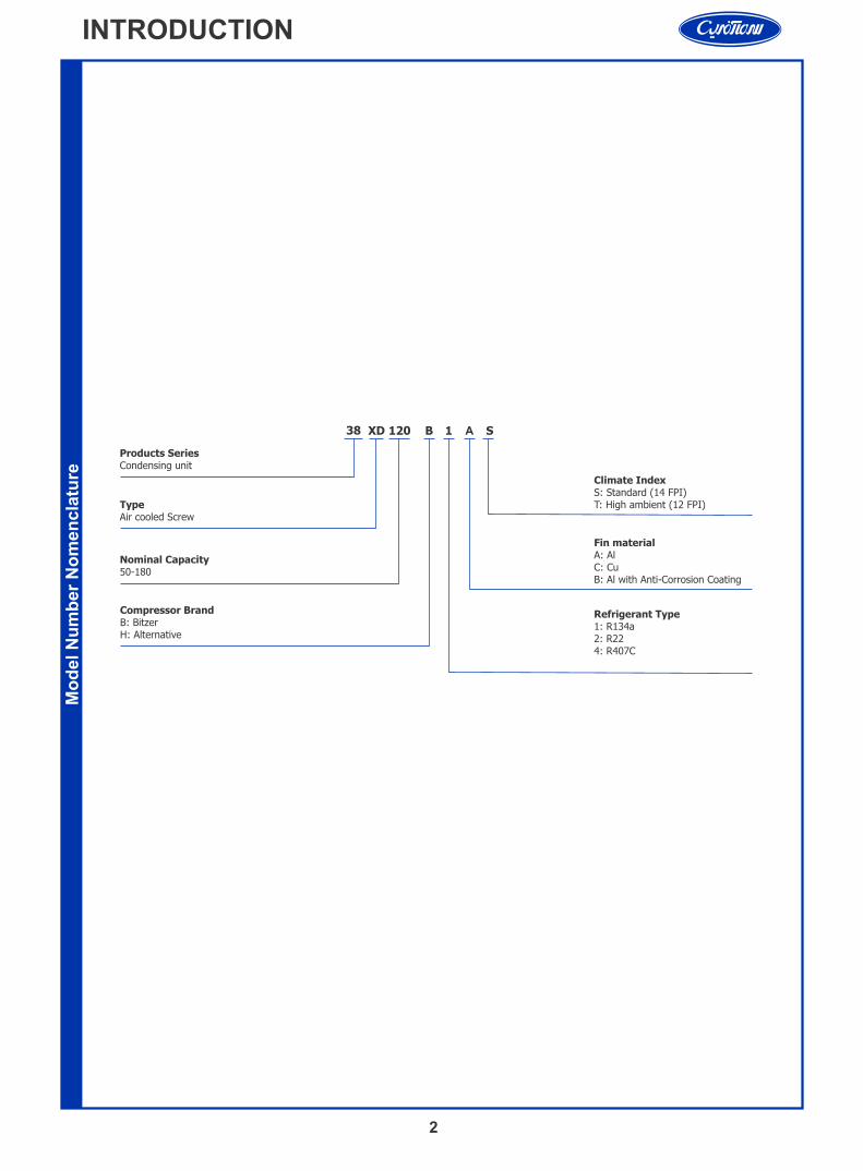
A38 XD 120 B 1 S
Products SeriesCondensing unit
TypeAir cooled Screw
Nominal Capacity50-180
Compressor BrandB: BitzerH: Alternative
Fin material A: AlC: CuB: Al with Anti-Corrosion Coating
Refrigerant Type1: R134a2: R224: R407C
Climate IndexS: Standard (14 FPI)T: High ambient (12 FPI)
Op
era
tin
g W
eig
ht*
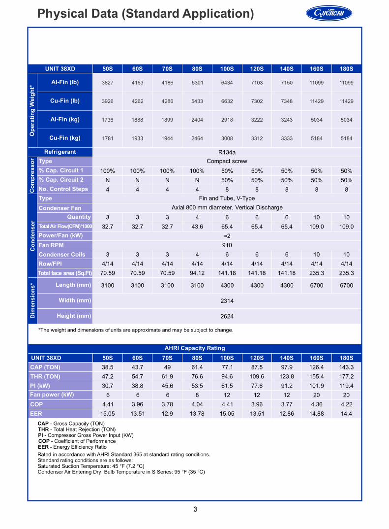
UNIT 38XD 50S 60S 70S 80S 100S 120S 140S 160S 180S
Al-Fin (lb)
Refrigerant R134a
Co
mp
res
so
r Compact screw
100% 100% 100% 100% 50% 50% 50% 50% 50%
N N N N 50% 50% 50% 50% 50%
4 4 4 4 8 8 8 8 8
Co
nd
en
ser
Fin and Tube, V-Type
Axial 800 mm diameter, Vertical Discharge
3 3 3 4 6 6 6 10 10
32.7 32.7 32.7 43.6 65.4 65.4 65.4 109.0 109.0
≈2
910
3 3 3 4 6 6 6 10 10
4/14 4/14 4/14 4/14 4/14 4/14 4/14 4/14 4/14
Total face area (Sq.Ft) 70.59 70.59 70.59 94.12 141.18 141.18 141.18 235.3 235.3
Dim
en
sio
ns* 3100 3100 3100 3100 4300 4300 4300 6700 6700
2314
2624
AHRI Capacity Rating
Cu-Fin (lb)
Al-Fin (kg)
Cu-Fin (kg)
CAP - Gross Capacity (TON)THR - Total Heat Rejection (TON)PI - Compressor Gross Power Input (KW)COP - Coefficient of Performance EER - Energy Efficiency Ratio
Rated in accordance with AHRI Standard 365 at standard rating conditions. Standard rating conditions are as follows:Saturated Suction Temperature: 45 °F (7.2 °C)
Type
% Cap. Circuit 1
% Cap. Circuit 2
No. Control Steps
Type
Condenser Fan
Total Air Flow(CFM)*1000
Power/Fan (kW)
Fan RPM
Condenser Coils
Row/FPI
Quantity
Length (mm)
Width (mm)
Height (mm)
*The weight and dimensions of units are approximate and may be subject to change.
UNIT 38XD
CAP (TON)
THR (TON)
PI (kW)
Fan power (kW)
COP
EER
50S 60S 70S 80S 100S 120S 140S 160S 180S
38.5 43.7 49 61.4 77.1 87.5 97.9 126.4 143.3
47.2 54.7 61.9 76.6 94.6 109.6 123.8 155.4 177.2
30.7 38.8 45.6 53.5 61.5 77.6 91.2 101.9 119.4
6 6 6 8 12 12 12 20 20
4.41 3.96 3.78 4.04 4.41 3.96 3.77 4.36 4.22
15.05 13.51 12.9 13.78 15.05 13.51 12.86 14.88 14.4
3
Physical Data (Standard Application)
Condenser Air Entering Dry Bulb Temperature in S Series: 95 °F (35 °C)
3827 4163 4186 5301 6434 7103 7150 11099 11099
3926 4262 4286 5433 6632 7302 7348 11429 11429
1736 1888 1899 2404 2918 3222 3243 5034 5034
1781 1933 1944 2464 3008 3312 3333 5184 5184
Op
era
tin
g W
eig
ht*
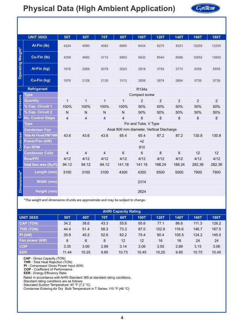
UNIT 38XD
Al-Fin (lb)
Refrigerant R134a
Co
mp
res
so
rs
Compact screw
Co
nd
en
ser
Fin and Tube, V Type
Axial 800 mm diameter, Vertical Discharge
≈2
910
Total face area (Sq.Ft)
Dim
en
sio
ns*
2314
2624
AHRI Capacity Rating
Cu-Fin (lb)
Al-Fin (kg)
Cu-Fin (kg)
Rated in accordance with AHRI Standard 365 at standard rating conditions. Standard rating conditions are as follows:Saturated Suction Temperature: 45 °F (7.2 °C)
Type
Quantity
% Cap. Circuit 1
% Cap. Circuit 2
No. Control Steps
Type
Condenser Fan
Power/Fan (kW)
Fan RPM
Condenser Coils
Row/FPI
Length (mm)
Width (mm)
Height (mm)
*The weight and dimensions of units are approximate and may be subject to change.
UNIT 38XD
CAP (TON)
THR (TON)
PI (kW)
Fan power (kW)
COP
EER
50T 60T 70T 80T 100T 120T 140T 160T 180T
1 1 1 1 2 2 2 2 2
100% 100% 100% 100% 50% 50% 50% 50% 50%
N N N N 50% 50% 50% 50% 50%
4 4 4 4 8 8 8 8 8
43.6 43.6 43.6 65.4 65.4 87.2 87.2 130.8 130.8
4 4 4 6 6 8 8 12 12
4/12 4/12 4/12 4/12 4/12 4/12 4/12 4/12 4/12
94.12 94.12 94.12 141.18 141.18 188.24 188.24 282.36 282.36
3100 3100 3100 4300 4300 5500 5500 79007900
50T 60T 70T 80T 100T 120T 140T 160T 180T
34.2 38.6 43.3 55.6 65.6 77.1 86.6 111.3 126.2
44.4 51.4 58.3 73.3 87.0 102.8 116.6 146.7 167.5
35.9 45.2 52.8 62.2 75.4 90.4 105.5 124.2 145.0
8 8 8 12 12 16 16 24 24
3.35 3.00 2.89 3.14 3.06 3.00 2.89 3.15 3.06
11.44 10.25 9.85 10.73 10.45 10.25 9.85 10.75 10.45
4
Physical Data (High Ambient Application)
CAP - Gross Capacity (TON)THR - Total Heat Rejection (TON)PI - Compressor Gross Power Input (KW)COP - Coefficient of Performance EER - Energy Efficiency Ratio
Condenser Entering Air Dry Bulb Temperature in T Series: 115 °F (46 °C)
4224 4560 4583 6665 6434 8275 8321 12255 12255
4356 4692 4715 6863 6632 8540 8586 12652 12652
1916 2068 2079 3023 2918 3754 3774 5559 5559
1976 2128 2139 3113 3008 3874 3894 5739 5739
Total Air Flow(CFM)*1000
5
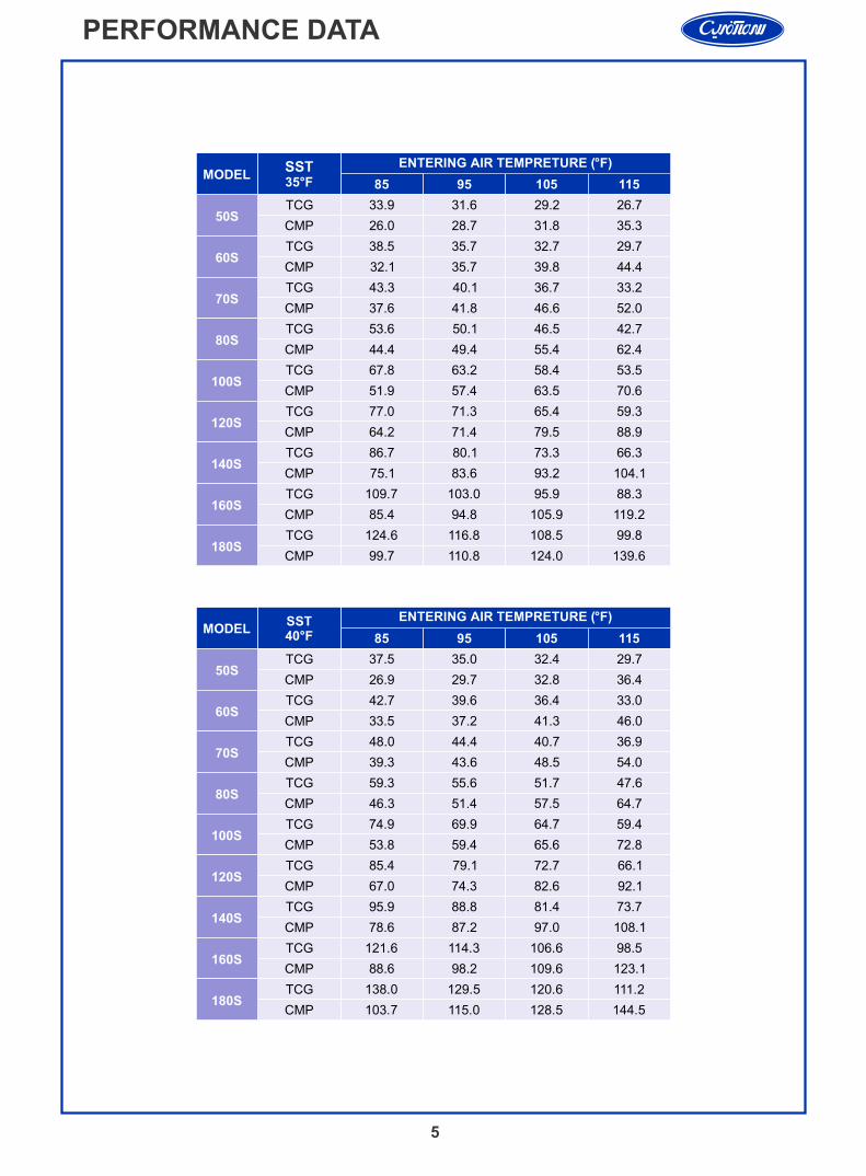
PERFORMANCE DATA
MODEL
SST35°F
ENTERING AIR TEMPRETURE (°F)
85 95 105 115
50STCG 33.9 31.6 29.2 26.7
CMP 26.0 28.7 31.8 35.3
60STCG 38.5 35.7 32.7 29.7
CMP 32.1 35.7 39.8 44.4
70STCG 43.3 40.1 36.7 33.2
CMP 37.6 41.8 46.6 52.0
80STCG 53.6 50.1 46.5 42.7
CMP 44.4 49.4 55.4 62.4
100STCG 67.8 63.2 58.4 53.5
CMP 51.9 57.4 63.5 70.6
120STCG 77.0 71.3 65.4 59.3
CMP 64.2 71.4 79.5 88.9
140STCG 86.7 80.1 73.3 66.3
CMP 75.1 83.6 93.2 104.1
160STCG 109.7 103.0 95.9 88.3
CMP 85.4 94.8 105.9 119.2
180STCG 124.6 116.8 108.5 99.8
CMP 99.7 110.8 124.0 139.6
MODEL85 95 105 115
50STCG 37.5 35.0 32.4 29.7
CMP 26.9 29.7 32.8 36.4
60STCG 42.7 39.6 36.4 33.0
CMP 33.5 37.2 41.3 46.0
70STCG 48.0 44.4 40.7 36.9
CMP 39.3 43.6 48.5 54.0
80STCG 59.3 55.6 51.7 47.6
CMP 46.3 51.4 57.5 64.7
100STCG 74.9 69.9 64.7 59.4
CMP 53.8 59.4 65.6 72.8
120STCG 85.4 79.1 72.7 66.1
CMP 67.0 74.3 82.6 92.1
140STCG 95.9 88.8 81.4 73.7
CMP 78.6 87.2 97.0 108.1
160STCG 121.6 114.3 106.6 98.5
CMP 88.6 98.2 109.6 123.1
180STCG 138.0 129.5 120.6 111.2
CMP 103.7 115.0 128.5 144.5
ENTERING AIR TEMPRETURE (°F)SST40°F
6
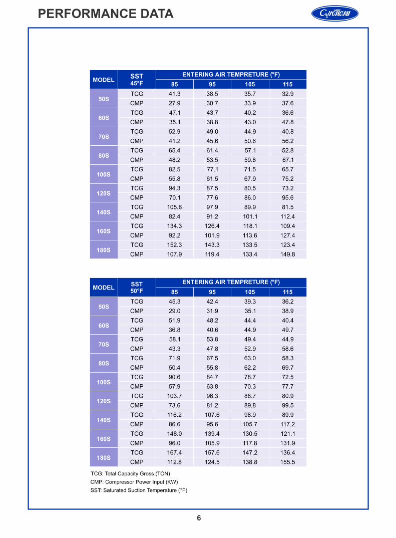
PERFORMANCE DATA
MODEL
SST45°F
ENTERING AIR TEMPRETURE (°F)
85 95 105 115
50S
60S
70S
80S
100S
120S
140S
160S
180S
MODEL85 95 105 115
50S
60S
70S
80S
100S
120S
140S
160S
180S
ENTERING AIR TEMPRETURE (°F)SST50°F
41.3 38.5 35.7 32.9
27.9 30.7 33.9 37.6
47.1 43.7 40.2 36.6
35.1 38.8 43.0 47.8
52.9 49.0 44.9 40.8
41.2 45.6 50.6 56.2
65.4 61.4 57.1 52.8
48.2 53.5 59.8 67.1
82.5 77.1 71.5 65.7
55.8 61.5 67.9 75.2
94.3 87.5 80.5 73.2
70.1 77.6 86.0 95.6
105.8 97.9 89.9 81.5
82.4 91.2 101.1 112.4
134.3 126.4 118.1 109.4
92.2 101.9 113.6 127.4
152.3 143.3 133.5 123.4
107.9 119.4 133.4 149.8
45.3 42.4 39.3 36.2
29.0 31.9 35.1 38.9
51.9 48.2 44.4 40.4
36.8 40.6 44.9 49.7
58.1 53.8 49.4 44.9
43.3 47.8 52.9 58.6
71.9 67.5 63.0 58.3
50.4 55.8 62.2 69.7
90.6 84.7 78.7 72.5
57.9 63.8 70.3 77.7
103.7 96.3 88.7 80.9
73.6 81.2 89.8 99.5
116.2 107.6 98.9 89.9
86.6 95.6 105.7 117.2
148.0 139.4 130.5 121.1
96.0 105.9 117.8 131.9
167.4 157.6 147.2 136.4
112.8 124.5 138.8 155.5
TCG
CMP
TCG
CMP
TCG
CMP
TCG
CMP
TCG
CMP
TCG
CMP
TCG
CMP
TCG
CMP
TCG
CMP
TCG
CMP
TCG
CMP
TCG
CMP
TCG
CMP
TCG
CMP
TCG
CMP
TCG
CMP
TCG
CMP
TCG
CMP
TCG: Total Capacity Gross (TON)
CMP: Compressor Power Input (KW)
SST: Saturated Suction Temperature (°F)
7
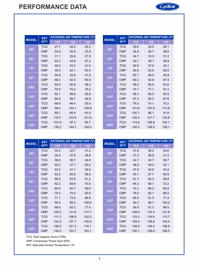
PERFORMANCE DATA
MODEL 115 120 125
ENTERING AIR TEMPRETURE (°F)SST35°F
MODEL
MODELENTERING AIR TEMPRETURE (°F)SST
50°F
ENTERING AIR TEMPRETURE (°F)SST40°F 115 120 125
115 120 125
50T
60T
70T
80T
100T
120T
140T
160T
180T
MODEL
50T
60T
70T
80T
100T
120T
140T
160T
180T
ENTERING AIR TEMPRETURE (°F)SST45°F
50T
60T
70T
80T
100T
120T
140T
160T
180T
50T
60T
70T
80T
100T
120T
140T
160T
180T
115 120 125
TCG 27.7 26.5 25.2
CMP 33.9 35.8 37.8
TCG 31.1 29.5 27.9
CMP 42.3 44.8 47.4
TCG 35.0 33.2 31.5
CMP 49.3 52.1 54.9
TCG 44.9 42.9 41.0
CMP 58.3 62.0 65.9
TCG 53.4 50.8 48.3
CMP 70.9 75.0 79.2
TCG 62.1 58.9 55.8
CMP 84.6 89.7 94.8
TCG 69.9 66.4 63.0
CMP 98.4 104.1 109.8
TCG 89.7 85.9 81.9
CMP 116.7 123.9 131.8
TCG 101.6 97.2 92.7
CMP 136.2 144.7 154.0
TCG 34.2 32.7 31.2
CMP 35.9 37.8 39.8
TCG 38.6 36.7 34.8
CMP 45.2 47.7 50.4
TCG 43.3 41.1 39.0
CMP 52.8 55.8 58.9
TCG 55.6 53.5 51.2
CMP 62.2 65.8 70.0
TCG 65.6 62.7 59.9
CMP 75.4 79.4 83.8
TCG 77.1 73.5 69.6
CMP 90.4 95.3 100.9
TCG 86.6 82.2 77.9
CMP 105.5 111.6 117.7
TCG 111.3 106.9 102.3
CMP 124.2 131.7 140.0
TCG 126.2 121.2 116.1
CMP 145.0 153.7 163.1
TCG 30.8 29.5 28.1
CMP 34.8 36.7 38.8
TCG 34.7 33.0 31.2
CMP 43.7 46.1 48.8
TCG 39.0 37.0 35.1
CMP 50.9 53.8 56.8
TCG 50.1 48.0 45.9
CMP 60.2 63.8 67.9
TCG 59.2 56.5 53.8
CMP 73.1 77.1 81.4
TCG 69.3 66.0 62.5
CMP 87.4 92.2 97.6
TCG 78.0 74.1 70.2
CMP 101.8 107.6 113.6
TCG 100.1 96.1 91.8
CMP 120.3 127.7 135.8
TCG 113.6 108.8 104.1
CMP 140.3 148.9 158.1
TCG 37.8 36.2 34.6
CMP 37.0 38.9 41.0
TCG 42.7 40.7 38.7
CMP 46.9 49.4 52.1
TCG 47.9 45.6 43.2
CMP 54.7 57.7 60.9
TCG 61.7 59.3 56.9
CMP 64.3 68.1 72.2
TCG 72.3 69.2 65.9
CMP 78.0 82.1 86.5
TCG 85.5 81.5 77.3
CMP 93.7 98.7 104.2
TCG 95.9 91.2 86.5
CMP 109.5 115.4 121.8
TCG 123.3 118.6 113.7
CMP 128.5 136.0 144.4
TCG 139.8 134.4 128.9
CMP 150.1 158.9 168.5
TCG: Total Capacity Gross (TON)
CMP: Compressor Power Input (KW)
SST: Saturated Suction Temperature (°F)
8
APPLICATION DATA
Field InstallationT/EXV valve The expansion valve sensing bulb must be installed after at least two 90 bends at the evaporator outlet.Ideally the expansion valve should be installed in a vertical pipe run. If that is not possible, the valve may be rotated through a full 90, with the horizontal pipe remaining at the base.
Solenoid Valve Liquid line solenoid valves are necessary, either with single circuit or with dual-circuit. The solenoid valve should be controlled in case of evaporators be deactivated in the upper section of the evaporator coil and reduce the load on the compressor (capacity un-loaders operated by suction pressure).
Installation of PipingCaution: - In order to prevent vibration and possible pipe breaks install proper pipe supports for all pipes at the point where they leave the unit.The design and operation of refrigerant piping systems should:- Ensure proper refrigerant feed to evaporators.- Provide practical refrigerant line sizes without excessive pressure drop.- Prevent excessive amounts of lubricating oil from being trapped in any part of the system.- Protect the compressor at all times from loss of lubricating oil.- Prevent liquid refrigerant or oil slugs from entering the compressor during operating and idle time.- Maintain a clean and dry system
Liquid accessories The filter-drier should have maximum unit capacity and minimum pressure drop and should be installed before the expansion valve and the moisture indicator just after the shut-off valve in the same line. These are available as factory-ordered. It is somehow obligatory to install a moisture indicator in liquid line just after condenser to be sure about the refrigerant charge. Oil Return Condensing units with multiple-step unloading may require double suction risers to ensure proper oil return at minimum load. The refrigerant suction line should be insulated in accordance with the guidelines set forth in the “Carrier System Design Manual”.The more important point is that, the oil charge must be adjusted to allow for extra line length. This is done by adding 1% of the nominal oil charge for the compressor every 3 m of piping in excess of 16 m. When Sizing the refrigerant lines, consider the length of piping required between condensing unit and evaporator, the amount of liquid lift, and the compressor oil return. Refer to the dimensional drawings for the size, type and location of the suction and liquid line pipe connections. Refer to the “Carrier System Design Manual”. Include a liquid receiver in the installation if it seems to be necessary.
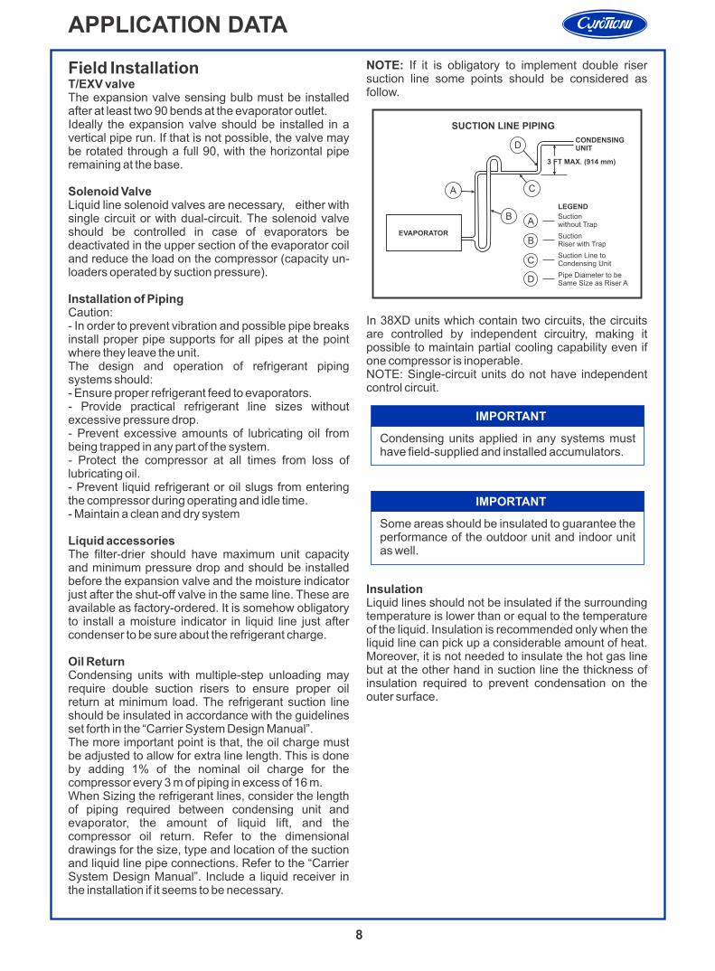
NOTE: If it is obligatory to implement double riser suction line some points should be considered as follow.
In 38XD units which contain two circuits, the circuits are controlled by independent circuitry, making it possible to maintain partial cooling capability even if one compressor is inoperable.NOTE: Single-circuit units do not have independent control circuit.
InsulationLiquid lines should not be insulated if the surrounding temperature is lower than or equal to the temperature of the liquid. Insulation is recommended only when the liquid line can pick up a considerable amount of heat. Moreover, it is not needed to insulate the hot gas line but at the other hand in suction line the thickness of insulation required to prevent condensation on the outer surface.
Condensing units applied in any systems must have field-supplied and installed accumulators.
IMPORTANT
B
A C
DCONDENSINGUNIT
3 FT MAX. (914 mm)
EVAPORATOR
SUCTION LINE PIPING
LEGEND
Suctionwithout Trap
SuctionRiser with Trap
Suction Line toCondensing Unit
Pipe Diameter to beSame Size as Riser A
A
B
C
D
Some areas should be insulated to guarantee the performance of the outdoor unit and indoor unit as well.
IMPORTANT
9
APPLICATION DATA
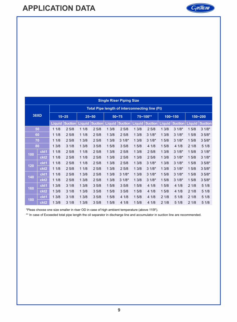
*Pleas choose one size smaller in riser OD in case of high ambient temperature (above 115F).
** In case of Exceeded total pipe length the oil separator in discharge line and accumulator in suction line are recommended.
38XD
Total Pipe length of interconnecting line (Ft)
15~25 25~50 50~75 75~100** 100~150 150~200
LiquidLiquidLiquidLiquidLiquidLiquid SuctionSuctionSuctionSuctionSuctionSuction
50 1 1/8 2 5/8 1 1/8 2 5/8 1 3/8 2 5/8 1 3/8 2 5/8 1 3/8 3 1/8* 1 5/8 3 1/8*
60 1 1/8 2 5/8 1 1/8 2 5/8 1 3/8 2 5/8 1 3/8 3 1/8* 1 3/8 3 1/8* 1 5/8 3 5/8*
70 1 1/8 2 5/8 1 3/8 2 5/8 1 3/8 3 1/8* 1 3/8 3 1/8* 1 5/8 3 1/8* 1 5/8 3 5/8*
80 1 3/8 3 1/8 1 3/8 3 5/8 1 5/8 3 5/8 1 5/8 4 1/8 1 5/8 4 1/8 2 1/8 5 1/8
100ckt1
ckt1
ckt1
ckt1
ckt1
1 1/8 2 5/8 1 1/8 2 5/8 1 3/8 2 5/8 1 3/8 2 5/8 1 3/8 3 1/8* 1 5/8 3 1/8*
ckt2
ckt2
ckt2
ckt2
ckt2
1 1/8 2 5/8 1 1/8 2 5/8 1 3/8 2 5/8 1 3/8 2 5/8 1 3/8 3 1/8* 1 5/8 3 1/8*
1201 1/8 2 5/8 1 1/8 2 5/8 1 3/8 2 5/8 1 3/8 3 1/8* 1 3/8 3 1/8* 1 5/8 3 5/8*
1 1/8 2 5/8 1 1/8 2 5/8 1 3/8 2 5/8 1 3/8 3 1/8* 1 3/8 3 1/8* 1 5/8 3 5/8*
1401 1/8 2 5/8 1 3/8 2 5/8 1 3/8 3 1/8* 1 3/8 3 1/8* 1 5/8 3 1/8* 1 5/8 3 5/8*
1 1/8 2 5/8 1 3/8 2 5/8 1 3/8 3 1/8* 1 3/8 3 1/8* 1 5/8 3 1/8* 1 5/8 3 5/8*
1601 3/8 3 1/8 1 3/8 3 5/8 1 5/8 3 5/8 1 5/8 4 1/8 1 5/8 4 1/8 2 1/8 5 1/8
1 3/8 3 1/8 1 3/8 3 5/8 1 5/8 3 5/8 1 5/8 4 1/8 1 5/8 4 1/8 2 1/8 5 1/8
1801 3/8 3 1/8 1 3/8 3 5/8 1 5/8 4 1/8 1 5/8 4 1/8 2 1/8 5 1/8 2 1/8 5 1/8
1 3/8 3 1/8 1 3/8 3 5/8 1 5/8 4 1/8 1 5/8 4 1/8 2 1/8 5 1/8 2 1/8 5 1/8
Single Riser Piping Size
10
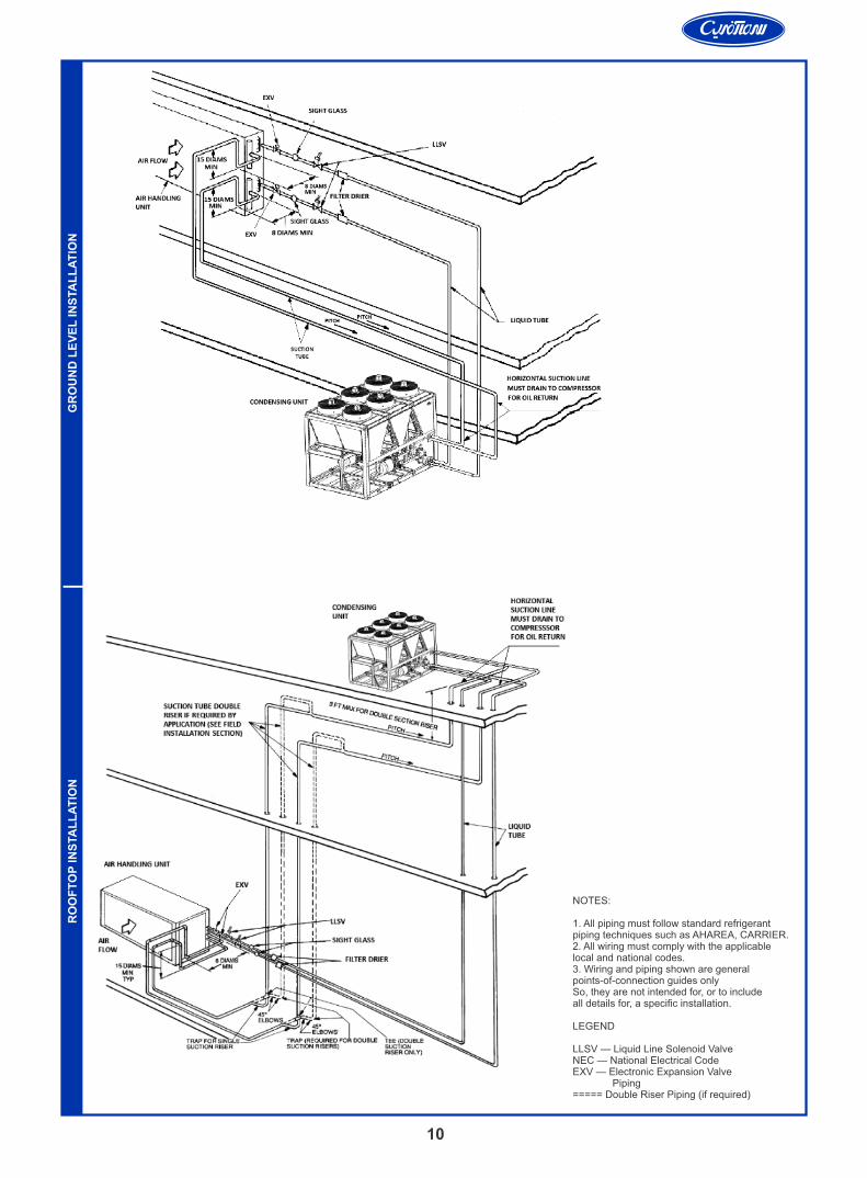
NOTES:
1. All piping must follow standard refrigerantpiping techniques such as AHAREA, CARRIER. 2. All wiring must comply with the applicablelocal and national codes.3. Wiring and piping shown are generalpoints-of-connection guides only So, they are not intended for, or to includeall details for, a specific installation.
LEGEND
LLSV — Liquid Line Solenoid ValveNEC — National Electrical CodeEXV — Electronic Expansion Valve Piping===== Double Riser Piping (if required)
RO
OF
TO
P IN
STA
LL
AT
ION
GR
OU
ND
LE
VE
L IN
STA
LL
AT
ION
ALTITUDE
(ft) (m)
CAPACITYMULTIPLIER
COMPRESSOR POWERMULTIPLIER
1.01
1.02
1.03
1.04
1.05
0.99
0.98
0.97
0.96
0.95
609.6
1219.2
1828.8
2438.4
3048
2000
4000
6000
8000
10000
ALTITUDE CORRECTION FACTORS
11
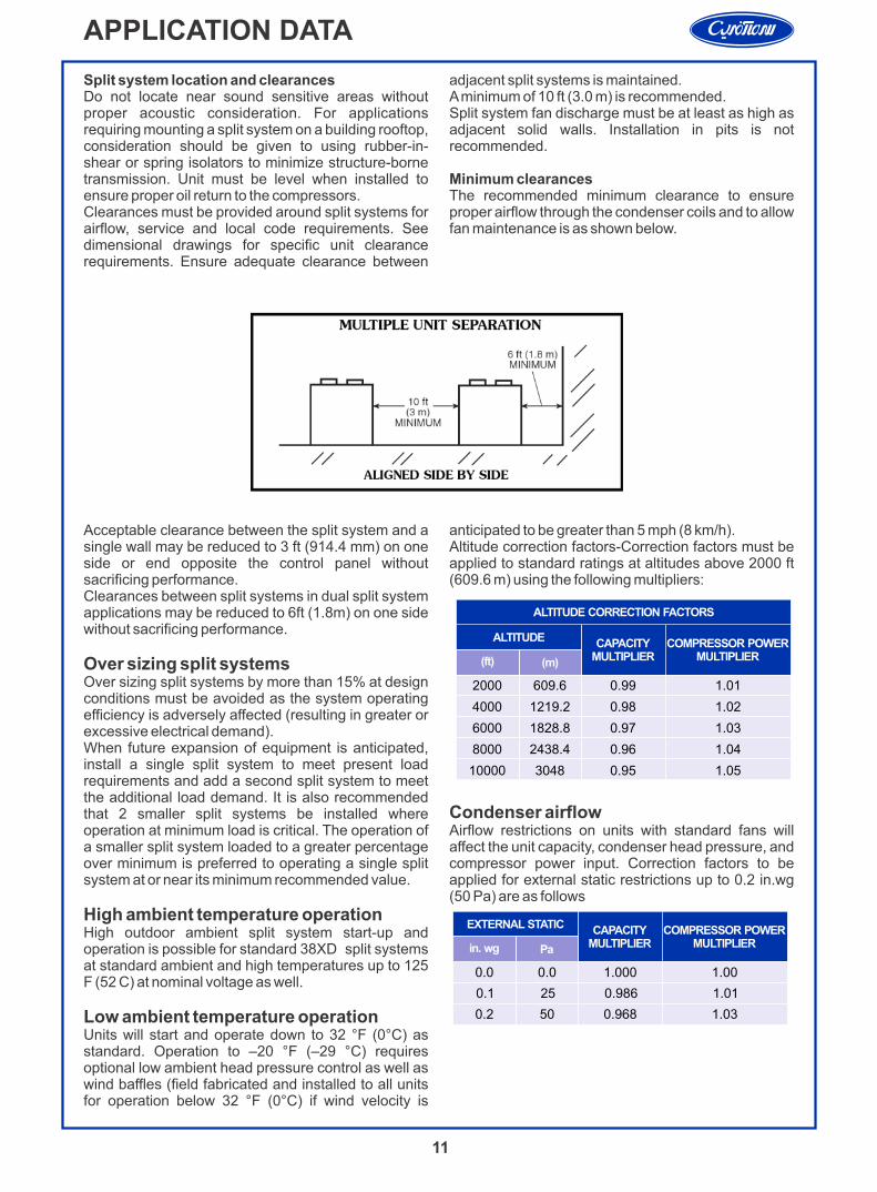
Acceptable clearance between the split system and a single wall may be reduced to 3 ft (914.4 mm) on one side or end opposite the control panel without sacrificing performance.Clearances between split systems in dual split system applications may be reduced to 6ft (1.8m) on one side without sacrificing performance.
Over sizing split systemsOver sizing split systems by more than 15% at design conditions must be avoided as the system operating efficiency is adversely affected (resulting in greater or excessive electrical demand). When future expansion of equipment is anticipated, install a single split system to meet present load requirements and add a second split system to meet the additional load demand. It is also recommended that 2 smaller split systems be installed where operation at minimum load is critical. The operation of a smaller split system loaded to a greater percentage over minimum is preferred to operating a single split system at or near its minimum recommended value.
High ambient temperature operationHigh outdoor ambient split system start-up and operation is possible for standard 38XD split systems at standard ambient and high temperatures up to 125 F (52 C) at nominal voltage as well.
Low ambient temperature operationUnits will start and operate down to 32 °F (0°C) as standard. Operation to –20 °F (–29 °C) requires optional low ambient head pressure control as well as wind baffles (field fabricated and installed to all units for operation below 32 °F (0°C) if wind velocity is
anticipated to be greater than 5 mph (8 km/h).Altitude correction factors-Correction factors must be applied to standard ratings at altitudes above 2000 ft (609.6 m) using the following multipliers:
Condenser airflow Airflow restrictions on units with standard fans will affect the unit capacity, condenser head pressure, and compressor power input. Correction factors to be applied for external static restrictions up to 0.2 in.wg (50 Pa) are as follows
Split system location and clearancesDo not locate near sound sensitive areas without proper acoustic consideration. For applications requiring mounting a split system on a building rooftop, consideration should be given to using rubber-in-shear or spring isolators to minimize structure-borne transmission. Unit must be level when installed to ensure proper oil return to the compressors.Clearances must be provided around split systems for airflow, service and local code requirements. See dimensional drawings for specific unit clearance requirements. Ensure adequate clearance between
adjacent split systems is maintained.A minimum of 10 ft (3.0 m) is recommended.Split system fan discharge must be at least as high as adjacent solid walls. Installation in pits is not recommended.
Minimum clearancesThe recommended minimum clearance to ensure proper airflow through the condenser coils and to allow fan maintenance is as shown below.
APPLICATION DATA
EXTERNAL STATIC
in. wg Pa
CAPACITYMULTIPLIER
COMPRESSOR POWERMULTIPLIER
0.0
0.1
0.2
0.0
25
50
1.000
0.986
0.968
1.00
1.01
1.03
12
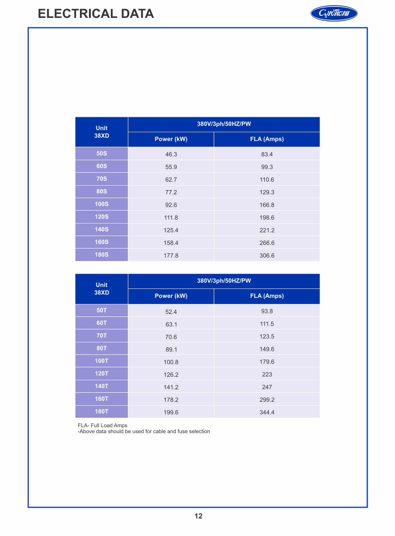
Unit
38XD
380V/3ph/50HZ/PW
50S
60S
70S
80S
100S
120S
140S
160S
180S
Power (kW) FLA (Amps)
50T
60T
Unit
38XD
380V/3ph/50HZ/PW
Power (kW) FLA (Amps)
70T
80T
100T
120T
140T
160T
180T
FLA- Full Load Amps-Above data should be used for cable and fuse selection
ELECTRICAL DATA
46.3 83.4
55.9 99.3
62.7 110.6
77.2 129.3
92.6 166.8
111.8 198.6
125.4 221.2
158.4 266.6
177.8 306.6
52.4 93.8
63.1 111.5
70.6 123.5
89.1 149.6
100.8 179.6
126.2 223
141.2 247
178.2 299.2
199.6 344.4
Sanaye Sarmaafarin Iran
شرکت صنایع سرما آفرین ایران(کریر ترموفریگ)
No. 194, W. Khorramshahr (Apadana) Ave., TEHRAN-15337, P. O. BOX: 13145-1799 Tel: 88762038 Fax: 88762033 www.sarmaafarin.com
سهروردي شمالی، خیابان خرمشهر، شماره 194، تهران - 15377، صندوق پستی: 1799-13145 تلفن: 88762038 فاکس: 88762033
Manufacturer reserves the right to discontinue or change at time, specifications of designs without notice and without incurring obliqations