Embed Size (px)
Citation preview
Commercial high-power X-band experience: klystron/modulators,
and waveguide vacuum flanges
CLIC Workshop January 2016
G. McMonagle
(on behalf of Xbox team)
• Klystrons
• Modulators
• Klystron Drivers
• Flanges
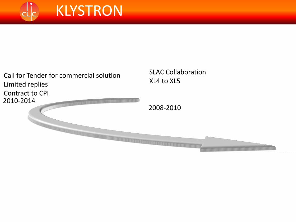
2008-2010
SLAC CollaborationXL4 to XL5
KLYSTRON
XL4 USA frequency 11.4 GHz only high power X band tube in operationNo commercial optionLong experience at SLAC in building and using these tubesCollaboration between CERN and SLAC to build 12 GHz design (XL5)PSI and Trieste joined collaboration5 tubes ordered“Best efforts” collaboration, no guarantees1st tube installed at CERN in 2010
KLYSTRON
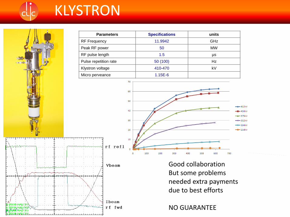
Parameters Specifications units
RF Frequency 11.9942 GHz
Peak RF power 50 MW
RF pulse length 1.5 µs
Pulse repetition rate 50 (100) Hz
Klystron voltage 410-470 kV
Micro perveance 1.15E-6
KLYSTRON
Good collaborationBut some problems needed extra payments due to best efforts
NO GUARANTEE
2008-2010
SLAC CollaborationXL4 to XL5
KLYSTRON
2010-2014
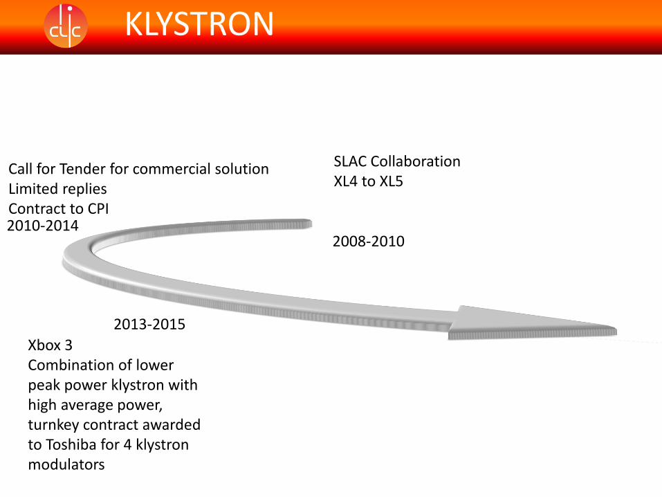
Call for Tender for commercial solutionLimited repliesContract to CPI
CPI VKX-8311ASame specification as XL5Ordered 2 new tubes plus option of buying a 3rd
1st tube successfully tested at SLACDelivered to CERN and installed in XBox1Tube has been performing fine since installation
2nd tube also successfully tested at SLACDelivered to CERN and installed in Xbox 2
During SAT tests problems arose with tube performance
KLYSTRON

KLYSTRON
First diode tests (no RF) of CPI#2 tube showed that 0.7 GHz gun oscillations starts at about 240 kV and even generate RF power from the input cavity:
Fortunately, going higher in voltage, the instability zone moves towards the rise/fall time, so the plat top can be used now.
No margin to reduceKlystron operation voltageRun at nominal even whenlow power required to avoid oscillations on RF
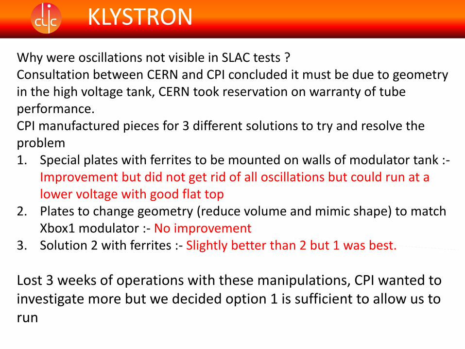
Why were oscillations not visible in SLAC tests ?Consultation between CERN and CPI concluded it must be due to geometry in the high voltage tank, CERN took reservation on warranty of tube performance.CPI manufactured pieces for 3 different solutions to try and resolve the problem1. Special plates with ferrites to be mounted on walls of modulator tank :-
Improvement but did not get rid of all oscillations but could run at a lower voltage with good flat top
2. Plates to change geometry (reduce volume and mimic shape) to match Xbox1 modulator :- No improvement
3. Solution 2 with ferrites :- Slightly better than 2 but 1 was best.
Lost 3 weeks of operations with these manipulations, CPI wanted to investigate more but we decided option 1 is sufficient to allow us to run
KLYSTRON
Are there any oscillations on 1st tube?
Yes but at within a small voltage at around 200kV and on falling edgeAbove and below these voltages tube is fine.
3rd tube has been ordered and will be tested in a new Scandinova modulator in CPI factory (not at SLAC) FAT next week
First indications from CPI are that there are no oscillations like 2nd
tube but may have similar issue to 1st, will find out more next week !
KLYSTRON
2008-2010
SLAC CollaborationXL4 to XL5
KLYSTRON
2010-2014
Call for Tender for commercial solutionLimited repliesContract to CPI
2013-2015
Xbox 3Combination of lower peak power klystron with high average power, turnkey contract awarded to Toshiba for 4 klystron modulators
KLYSTRON
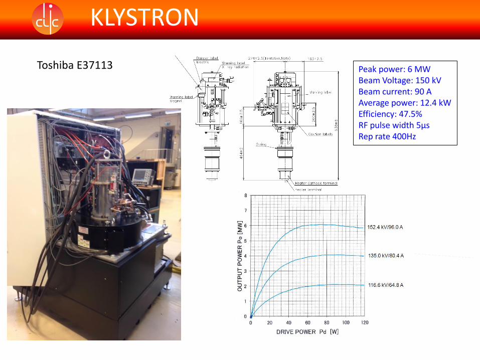
Toshiba E37113 Peak power: 6 MWBeam Voltage: 150 kVBeam current: 90 AAverage power: 12.4 kWEfficiency: 47.5% RF pulse width 5µsRep rate 400Hz
All 4 tubes have been successfully installed in the modulators at CERN in October 2015
All have pulsed to nominal parameters in diode mode
First tube has also been operating with RF
Waiting for delivery of RF waveguide components, LLRF and klystron drivers
RF commissioning hopefully starting March 2016
KLYSTRON
2010
Xbox 1
MODULATORS
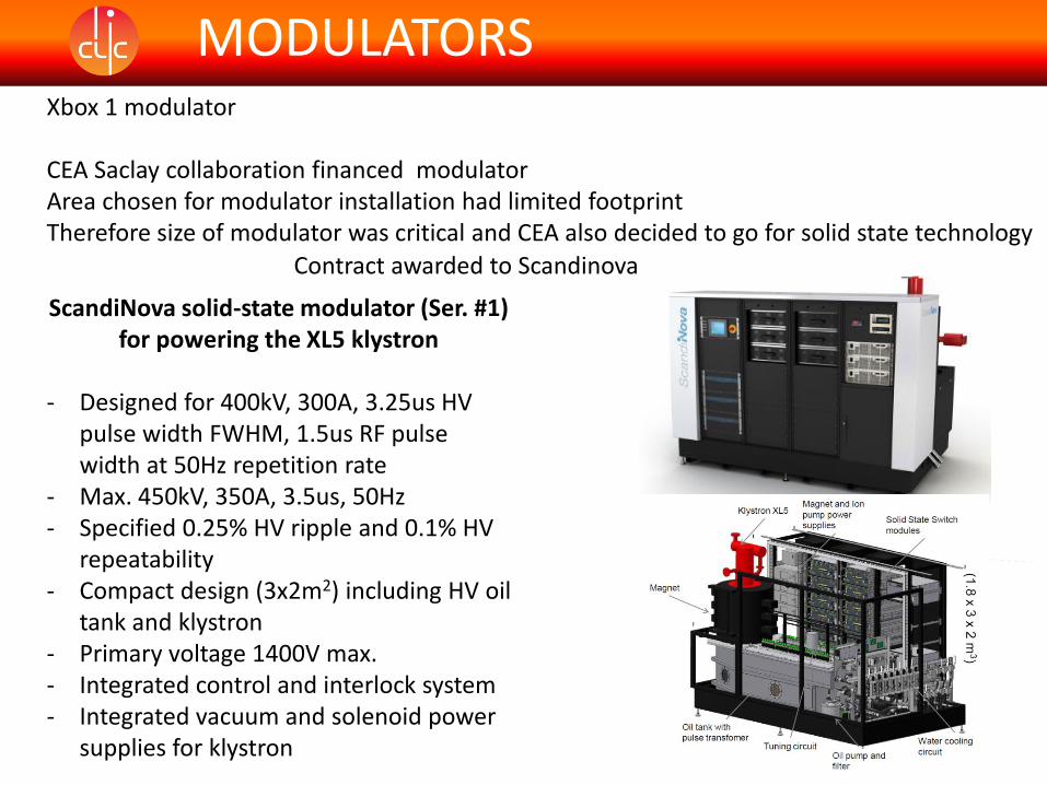
MODULATORSXbox 1 modulator
CEA Saclay collaboration financed modulatorArea chosen for modulator installation had limited footprintTherefore size of modulator was critical and CEA also decided to go for solid state technology
Contract awarded to Scandinova
ScandiNova solid-state modulator (Ser. #1)for powering the XL5 klystron
- Designed for 400kV, 300A, 3.25us HV pulse width FWHM, 1.5us RF pulse width at 50Hz repetition rate
- Max. 450kV, 350A, 3.5us, 50Hz- Specified 0.25% HV ripple and 0.1% HV
repeatability- Compact design (3x2m2) including HV oil
tank and klystron- Primary voltage 1400V max.- Integrated control and interlock system- Integrated vacuum and solenoid power
supplies for klystron
MODULATORS
Factory test done into dummy load (no klystron available)
Normally modulator delivered to client in fully assembled unit (as in factory) but due to space restrictions had to be disassembled the remounted at CERN
SAT tests with dummy load no klystron available
Did not achieve nominal parameters until 2015 with CPI klystron installed (arcing in SLAC klystron gun)

MODULATORS
Issues with 1st modulator
Calibration measurements.In factory no problem into resistive load (so we thought)
In SAT, modulator was commissioned with dummy load again as klystron was not delivered yet.
When klystron arrived was difficult to correlate measurements from SLAC to measurements at CERN, indications were that the perveance of tube was not correct.
Eventually found that SLAC measurements were erroneous by 10% (confirmed by Trieste during their acceptance of tube #3)
External Water
Cooling System
Filament
DCPS 0-
30A
Core
Bias
DCPS
HVPS
#1 - N
Control System Unit
P
o
w
e
r
D
i
s
tr
i
b
u
ti
o
n
U
n
it
L
1L
2L
3GN
D
Water Cooling Distribution
S
W
#3
S
W
#1
S
W
#2
S
W
#n
RF-
Source
RF-
Amplifie
r
Solenoid
PS #1-3
Ion
Pump
PS 5X
Modulator
>45 L/min
Collector
>120
L/minBody
>10
L/min
Solenoid
>10
L/min
Tri
gIpuls
eUpul
seRemote
RS232
12GH
z
400VAC
50Hz
Safety
Interface
3-
phase
480VA
C
1-phase
120VAC
Local RS232
K2 Solid
State
Modulator
Pulse
Transform
er Oil Tank
RF 3GHz
3x18
5A
C
T
CVD
Water Flow
Interlocks
Vacuum
Interlock
Current Interlock
Waveguide
pressure Int., Arc
Int, VSWR Int.
L
1NGN
D
230VAC
50Hz
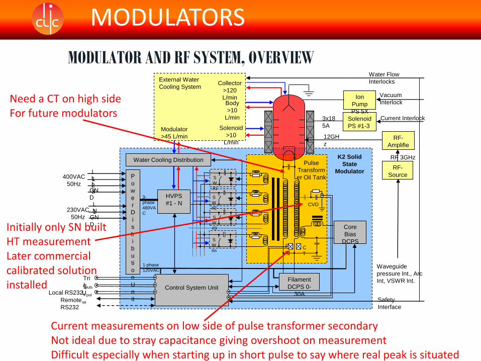
MODULATOR AND RF SYSTEM, OVERVIEW
MODULATORS
Current measurements on low side of pulse transformer secondaryNot ideal due to stray capacitance giving overshoot on measurementDifficult especially when starting up in short pulse to say where real peak is situated
Need a CT on high sideFor future modulators
Initially only SN built HT measurementLater commercial calibrated solution installed
MODULATORS
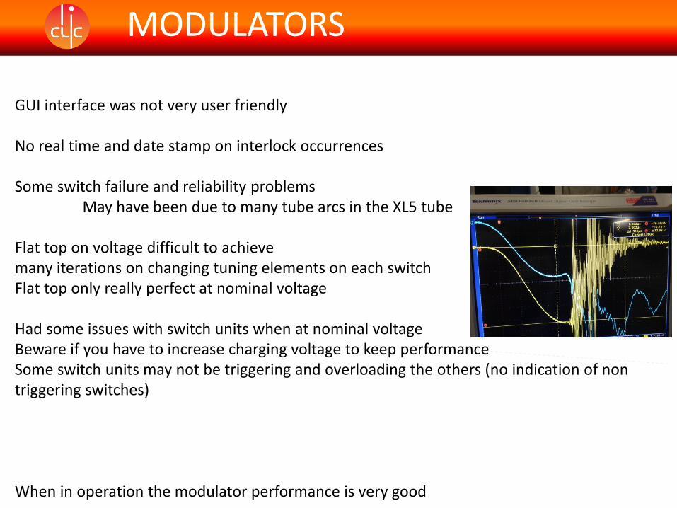
GUI interface was not very user friendly
No real time and date stamp on interlock occurrences
Some switch failure and reliability problemsMay have been due to many tube arcs in the XL5 tube
Flat top on voltage difficult to achieve many iterations on changing tuning elements on each switchFlat top only really perfect at nominal voltage
Had some issues with switch units when at nominal voltageBeware if you have to increase charging voltage to keep performanceSome switch units may not be triggering and overloading the others (no indication of non triggering switches)
When in operation the modulator performance is very good
2010
Xbox 1
MODULATORS
2012
Xbox 2
MODULATORSXbox 2 modulator competitive tender from CERN
Scandinova awarded contract
Measurement requests implemented into new unit (Calibrated CVD, CT on high side), but not real time and date stamp for intelocks
New design of switch unit (unfortunately not backward compatible with 1st unit)Different spares needed.
3 charging power supplies integrated (2 in first)
Unfortunately we decided to commission this modulator with the XL5 as there was pressure to put CPI tube #1 in Xbox1.Resulted in getting modulator to work correctly but not at full pulse width due to tube limitations.
Waited for CPI #2 to arrive before full commissioning and tuning of pulse shape
Apart from a few teething problems and of course tube oscillations system running very well
MODULATORS
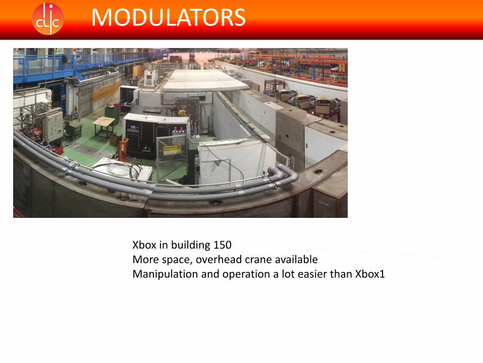
Xbox in building 150 More space, overhead crane availableManipulation and operation a lot easier than Xbox1
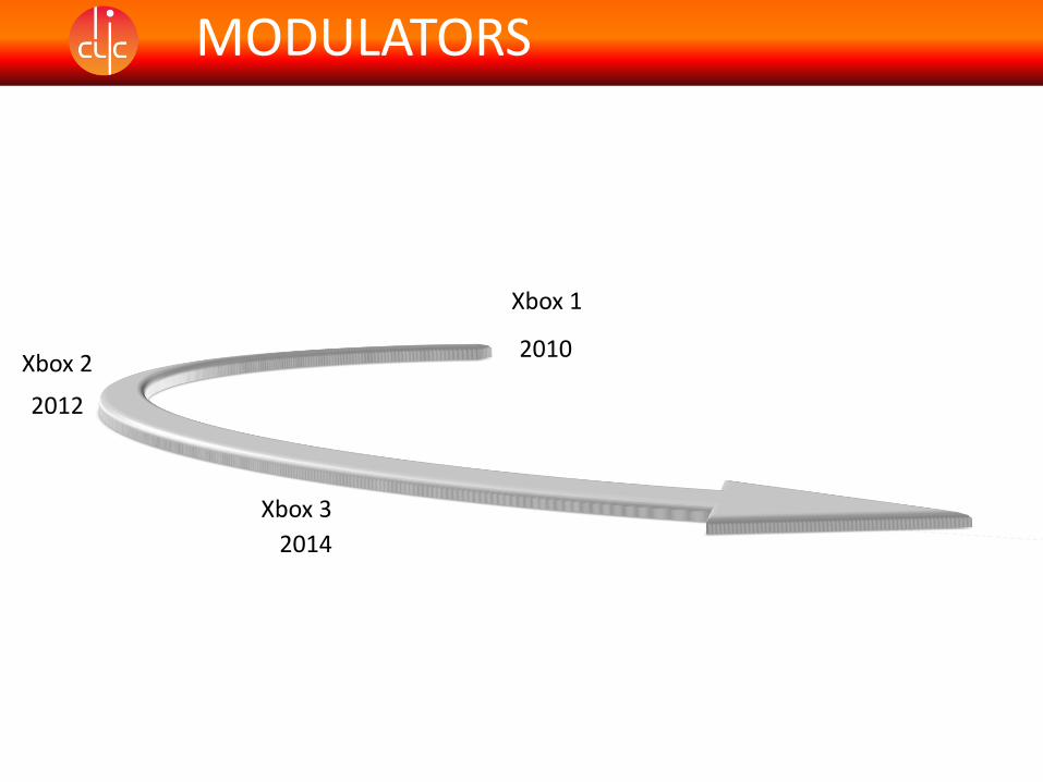
2010
Xbox 1
MODULATORS
2012
Xbox 2
Xbox 3
2014
MODULATORS
Lessons learnt from previous two projects
Price enquiry to klystron manufacturers for turnkey solution
Klystron contract awarded to Toshiba who subcontracted modulators to Scandinova
Tube and modulators arrived at CERN after full SAT test with klystron
Very quick and successful integration at CERN
MODULATORS
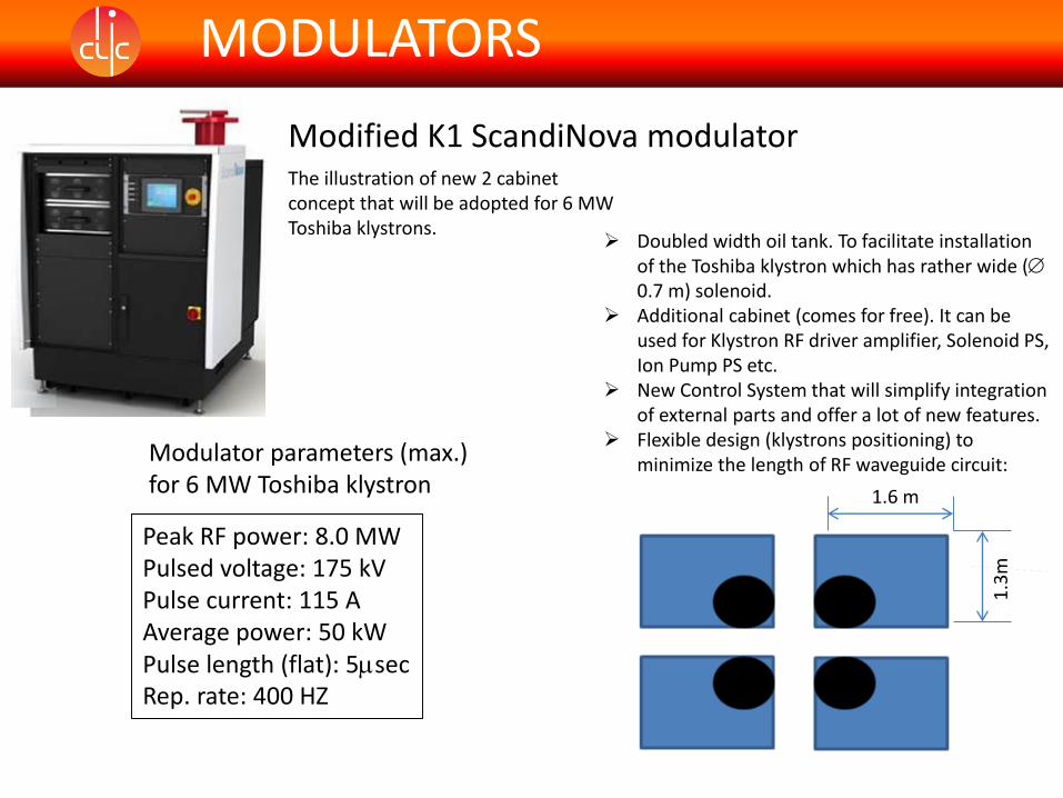
Modified K1 ScandiNova modulatorThe illustration of new 2 cabinet concept that will be adopted for 6 MW Toshiba klystrons.
Doubled width oil tank. To facilitate installation of the Toshiba klystron which has rather wide (0.7 m) solenoid.
Additional cabinet (comes for free). It can be used for Klystron RF driver amplifier, Solenoid PS, Ion Pump PS etc.
New Control System that will simplify integration of external parts and offer a lot of new features.
Flexible design (klystrons positioning) to minimize the length of RF waveguide circuit:Modulator parameters (max.)
for 6 MW Toshiba klystron
Peak RF power: 8.0 MWPulsed voltage: 175 kVPulse current: 115 AAverage power: 50 kWPulse length (flat): 5secRep. rate: 400 HZ
1.6 m
1.3
m

MODULATORS
Xbox 3 in building 150
Please sign up for visits later in the workshop
MODULATORS
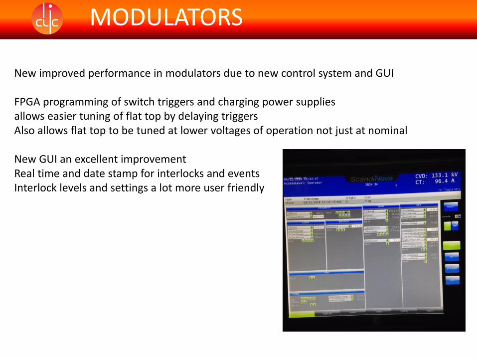
New improved performance in modulators due to new control system and GUI
FPGA programming of switch triggers and charging power supplies allows easier tuning of flat top by delaying triggersAlso allows flat top to be tuned at lower voltages of operation not just at nominal
New GUI an excellent improvementReal time and date stamp for interlocks and eventsInterlock levels and settings a lot more user friendly
MODULATORS
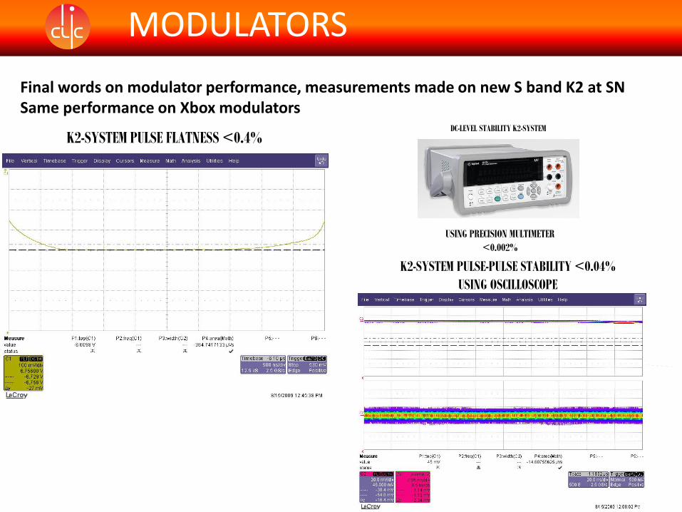
Final words on modulator performance, measurements made on new S band K2 at SNSame performance on Xbox modulators
K2-SYSTEM PULSE FLATNESS <0.4%DC-LEVEL STABILITY K2-SYSTEM
USING PRECISION MULTIMETER
<0.002%
K2-SYSTEM PULSE-PULSE STABILITY <0.04%
USING OSCILLOSCOPE
Klystron Drivers
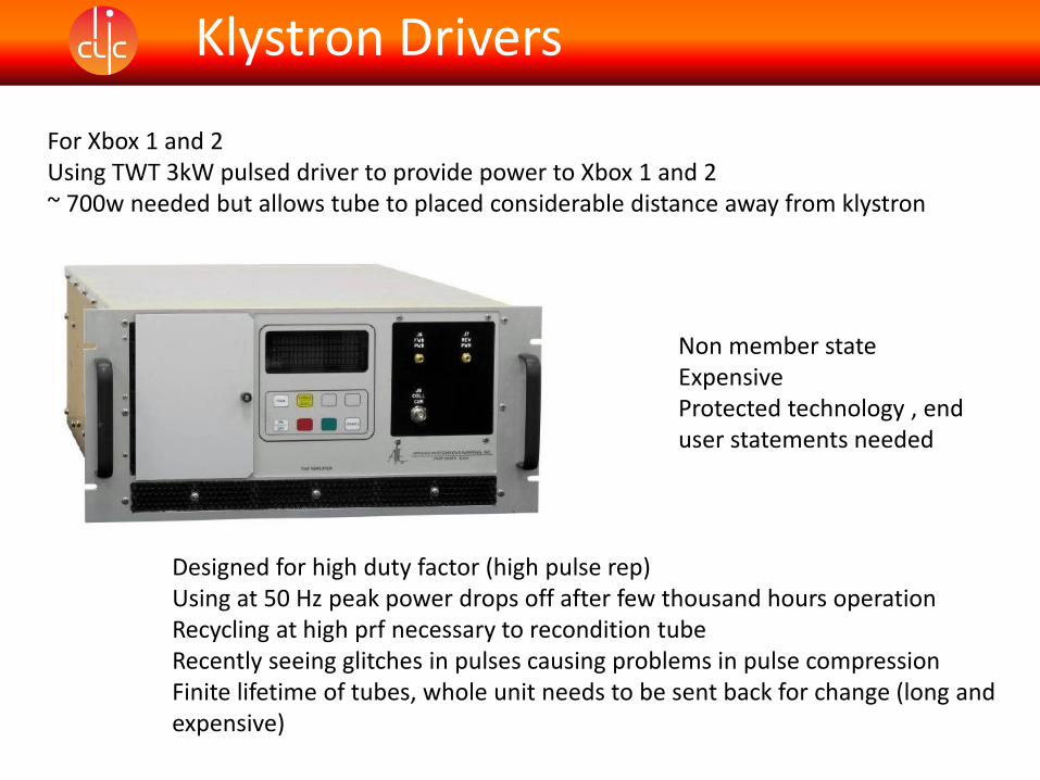
For Xbox 1 and 2 Using TWT 3kW pulsed driver to provide power to Xbox 1 and 2~ 700w needed but allows tube to placed considerable distance away from klystron
Non member stateExpensiveProtected technology , end user statements needed
Designed for high duty factor (high pulse rep)Using at 50 Hz peak power drops off after few thousand hours operationRecycling at high prf necessary to recondition tubeRecently seeing glitches in pulses causing problems in pulse compressionFinite lifetime of tubes, whole unit needs to be sent back for change (long and expensive)
Klystron Drivers
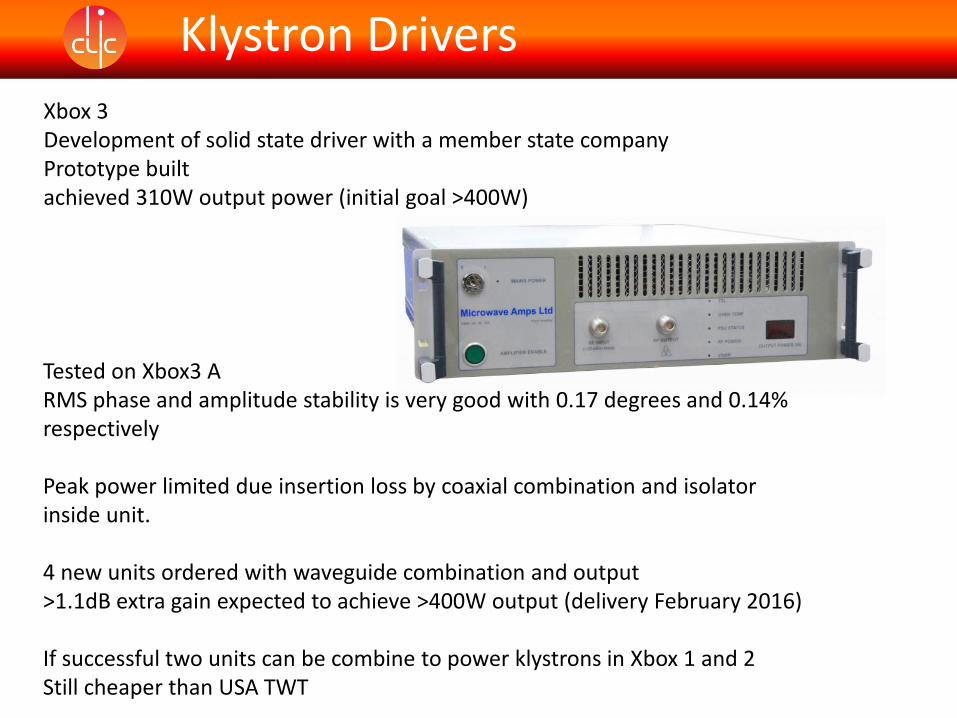
Xbox 3Development of solid state driver with a member state companyPrototype built achieved 310W output power (initial goal >400W)
Tested on Xbox3 ARMS phase and amplitude stability is very good with 0.17 degrees and 0.14% respectively
Peak power limited due insertion loss by coaxial combination and isolator inside unit.
4 new units ordered with waveguide combination and output>1.1dB extra gain expected to achieve >400W output (delivery February 2016)
If successful two units can be combine to power klystrons in Xbox 1 and 2Still cheaper than USA TWT
FLANGES
Xbox 1 and Xbox 2
Using SLAC type male/female type flange
Expensive to manufacture flanges and gaskets
Attention to detail on integration of “directional” components needed when choosing flanges.
Experience in Xbox 1 shows copper plating on flanges is necessary to reduce RF losses and RF heating
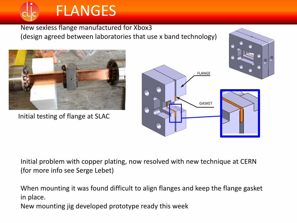
FLANGESNew sexless flange manufactured for Xbox3(design agreed between laboratories that use x band technology)
Initial problem with copper plating, now resolved with new technique at CERN(for more info see Serge Lebet)
When mounting it was found difficult to align flanges and keep the flange gasket in place.New mounting jig developed prototype ready this week
FLANGE
GASKET
Initial testing of flange at SLAC
Summary
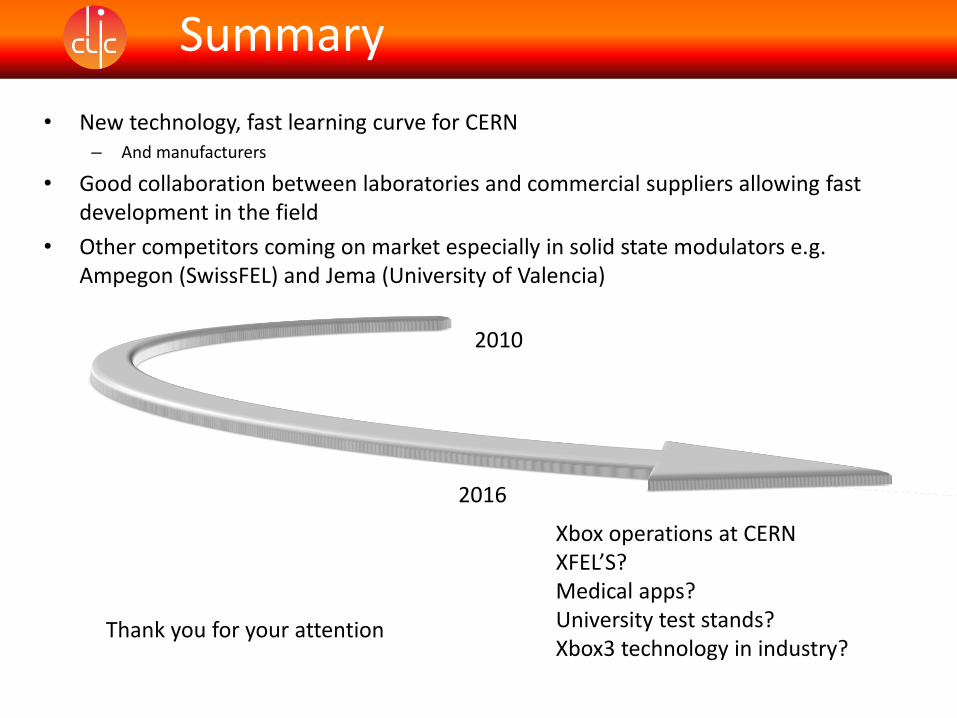
• New technology, fast learning curve for CERN– And manufacturers
• Good collaboration between laboratories and commercial suppliers allowing fast development in the field
• Other competitors coming on market especially in solid state modulators e.g. Ampegon (SwissFEL) and Jema (University of Valencia)
2010
2016
Xbox operations at CERNXFEL’S?Medical apps?University test stands?Xbox3 technology in industry?
Thank you for your attention