Embed Size (px)
Citation preview

ESA30E
Our Air Conditioning & Refrigeration Systems Headquarters is an ISO9001 approved factory for residential air conditioners and commercial-use air conditioners (including heat pumps).
ISO9001
BIWAJIMA PLANT Mitsubishi Heavy Industries, Ltd.
Air-conditioning & Refrigeration Systems HeadquartersCertified ISO 9001
Certificate number : JQA-0709
MITSUBISHI HEAVY INDUSTRIES-MAHAJAK AIR CONDITIONERS CO., LTD.
Certified ISO 9001Certificate Number : 04100 1998 0813
HB91-13HM01E-A-2 Oct. 2013(1B)R Because of our policy of continuous improvement, we reserve right to make changes in all specifications without notice.
Printed in Japan
MITSUBISHI HEAVY INDUSTRIES-MAHAJAK AIR CONDITIONERS CO.,LTD.
Certificate Number : 04104 1998 0813 E5
ISO 14001Certificate 04104 1998 0813 E5
Mitsubishi Heavy Industries, Ltd.Air-Conditioning & Refrigeration Systems Headquarters16-5, Konan 2-chome, Minato-ku, Tokyo, 108-8215 Japanhttp://www.mhi.co.jp
13HM01E-A-2
Commercial useHeat pump water heater
Ecological energyRecovering heat energy from the air
日本冷凍空調学会
技 術 賞(2012FY)

Free energy from the airOverwhelming high performanceand high efficiency
Next-generation system developed with our combines responsibility to global environment
Heat Pump Technology system
Q-ton’s unique advantages
Hot water supply system
P04 P06 P08
The world's firstThe world's firstCO2 two-stage compressor with the combination
of rotary and scroll compression cycles
is born
Installation samples
P10
Specifications and dimensions
P12
Installation work
P14
The most ecological way for supplying hot water
Our Heat Pump series
ESA30E
30kW ~ 480kW (for commercial use)
Natural refrigerant CO2 Air to Water System
627kW ~ 3135kW (for industrial use)
Water to Water SystemHeat recovery type
Please refer to the other catalogue.
ETWCapacity/temperature
-30(°C) -20 -10 0 10 20 30 40 50 60 70 80 90 100
temperatureinput
output
0(kW) 100 500 1000
Capacity
ETWQ-ton
0302
-7°C 100%Keeping 100% capacity down to -7°C
COP4.3!The industry's highest COP levelCOP4.3 (In intermediate season)
Ecology
-25°C 90°CEven in the extremely cold regions with outdoor temperature as low as -25°C, 90°C water supply is possible
High Performance
Natural refrigerant CO2 Heat Pump Water Heater
"Our technology, Your tomorrow"
日本冷凍空調学会
技 術 賞
Q-ton (ESA 30-25 for the Japanese domestic market) received the Fiscal Year 2011 technology award from Japan Society of Refrigerating and Air Conditioning Engineers (JSRAE) as attached.
Activities of JSRAE1) Survey, research, education and training, awards and certificate recognition for entitled engineers and scientists 2) Organization of annual JSRAE meeting, roundtable conferences, training short courses and workshops, technical visits and other events. 3) Publication of monthly journal "Reito"(refrigeration), Transactions of JSRAE and various books, textbooks, and handbooks. 4) Liaison with the International Institute of Refrigeration, IIR. 5) Implementation of correspondence education system. 6) Other miscellaneous†activities essential to fulfil the objectives. http://www.jsrae.or.jp/jsrae/Eindex-2.html
Activities of ECCJ 1) Promotion of energy efficiency and conservation for the industry and commercial sectors2) Providing information for further dissemination of energy-saving equipment3) Providing information to encourage energy-saving lifestyle4) Publishing and education5) International cooperation6) National examination for the qualified energy managers and the traininghttp://www.asiaeec-col.eccj.or.jp/index.html
Q-ton (ESA 30-25 for the Japanese domestic market) received The 2011 Fiscal Year grand prize for Excellence in Energy Efficiency and Conservation in Products Category & Business Model Category from The Energy Conservation Center, Japan (ECCJ) as attached.
ESA 30-25 ESA 30-25

5,0000 10,000 15,000
(L /day)
for kitchen for bathroom
Supply centerof meals
school/company lunch center
Spa/company dormitory/recreation facility
city hotel/business hotel
big restaurantwedding venue
senior care home/hospital resort hotel
Heat Pump technology system
~Recommendable usage or customer~
0504
Typically less than 1kW of output heat energy can be produced by conventional oil or gas boilers. Heat pump technology is capable of producing up to 4.3kW of heat energy from 1kW of energy input making the system 4.3 times more efficient than traditional means. Furthermore using natural refrigerant can provide comprehensive solution for realization of low-carbon society.
Recovering heat of the air
What is a Heat Pump ? What is hot water supply by Heat Pump technology system ?Heat energy is absorbed from the outside air when it
passes through the outdoor unit; the energy is transported
to the indoor unit in the refrigerant [in this case CO2] within
the piping system. This eliminates the need to bore holes or
bury coils of pipes in the ground as used in conventional
ground source systems.
low temperature
high temperature
heat
Conventional heat pump water heaters have performance issues to solve
Supplying 90°C hot water at ambienttemperatures down to -25°CAchieving the industry's top level COP "4.3"(in intermediate season)
Keeping high capacity and high efficiency in cold conditions
Heat pump unit
heat transfer
Hot waterAir
Increasing refrigerant temperature through compressing process by compressor
Decreasing refrigerant temperature through expanding process by expansion valve
CO2 refrigerantAir source heat
Supply hot water
Supply waterOur development concept
Unventedcylinder
Unventedcylinder
Unventedcylinder
conventional models
Offering efficient energy saving is the greatest merit
Overwhelming high performance and high efficiency
is bornQ-ton
1.2.3.
4.
Dramatically reducing power consumptionIncreasing Low Carbon initiativeGWP(Global Warming Potential): 1 (R410 refrigerant:2090)
ODP(Ozone Depletion Potential): zero
Technology for Eco
4
1 2
3
CompressorCompressorRefrigerant
Hot water
Water
Heat energy from the outdoor air
CondenserEvaporator
Circulationpump
Circulationpump
Expansionvalve
Expansionvalve
Transferring the heat to water and supplying hot water
1. The outdoor unit captures the heat energy from the outdoor air (heat source) and increases its temperature through compressing process by compressor.2. The hot refrigerant (now in gas state) is routed to condenser.3. The refrigerant releases the heating energy to water for further distribution .4. The refrigerant (now in liquid state) is routed back to evaporator and this process is repeated.
In the operation under low outdoor temperature,heating capacity and heating
efficiency decrease significantly.

5,0000 10,000 15,000
(L /day)
for kitchen for bathroom
Supply centerof meals
school/company lunch center
Spa/company dormitory/recreation facility
city hotel/business hotel
big restaurantwedding venue
senior care home/hospital resort hotel
Heat Pump technology system
~Recommendable usage or customer~
0504
Typically less than 1kW of output heat energy can be produced by conventional oil or gas boilers. Heat pump technology is capable of producing up to 4.3kW of heat energy from 1kW of energy input making the system 4.3 times more efficient than traditional means. Furthermore using natural refrigerant can provide comprehensive solution for realization of low-carbon society.
Recovering heat of the air
What is a Heat Pump ? What is hot water supply by Heat Pump technology system ?Heat energy is absorbed from the outside air when it
passes through the outdoor unit; the energy is transported
to the indoor unit in the refrigerant [in this case CO2] within
the piping system. This eliminates the need to bore holes or
bury coils of pipes in the ground as used in conventional
ground source systems.
low temperature
high temperature
heat
Conventional heat pump water heaters have performance issues to solve
Supplying 90°C hot water at ambienttemperatures down to -25°CAchieving the industry's top level COP "4.3"(in intermediate season)
Keeping high capacity and high efficiency in cold conditions
Heat pump unit
heat transfer
Hot waterAir
Increasing refrigerant temperature through compressing process by compressor
Decreasing refrigerant temperature through expanding process by expansion valve
CO2 refrigerantAir source heat
Supply hot water
Supply water
Keeping high capacity and high
Our development concept
Unventedcylinder
Unventedcylinder
Unventedcylinder
conventional models
Offering efficient energy saving is the greatest merit
Overwhelming high performance and high efficiency
is born
efficiency in cold conditions
is bornQ-ton
1.2.3.
4.
Dramatically reducing power consumptionIncreasing Low Carbon initiativeGWP(Global Warming Potential): 1 (R410 refrigerant:2090)
ODP(Ozone Depletion Potential): zero
Technology for Eco
4
1 2
3
CompressorCompressorRefrigerant
Hot water
Water
Heat energy from the outdoor air
CondenserEvaporator
Circulationpump
Circulationpump
Expansionvalve
Expansionvalve
Transferring the heat to water and supplying hot water
1. The outdoor unit captures the heat energy from the outdoor air (heat source) and increases its temperature through compressing process by compressor.2. The hot refrigerant (now in gas state) is routed to condenser.3. The refrigerant releases the heating energy to water for further distribution .4. The refrigerant (now in liquid state) is routed back to evaporator and this process is repeated.
In the operation under low outdoor temperature,heating capacity and heating
efficiency decrease significantly.
By increasing refrigerant circulation, high eff iciency in low temperature can be achieved.
Intermediate pressure gas injection configuration
0706
[temperature(°CDB)]
[heating capacity (kW)]
[hot water:65°C]
Enough capacity even under low temperature
2515 20-25 -20 5 10-15 -10 -5 0
-7°C
Q-tonESA30
conventionalheat pump
-7
Can keep the same capacity down to -7°C of the outdoor temperature5
0
10
15
20
25
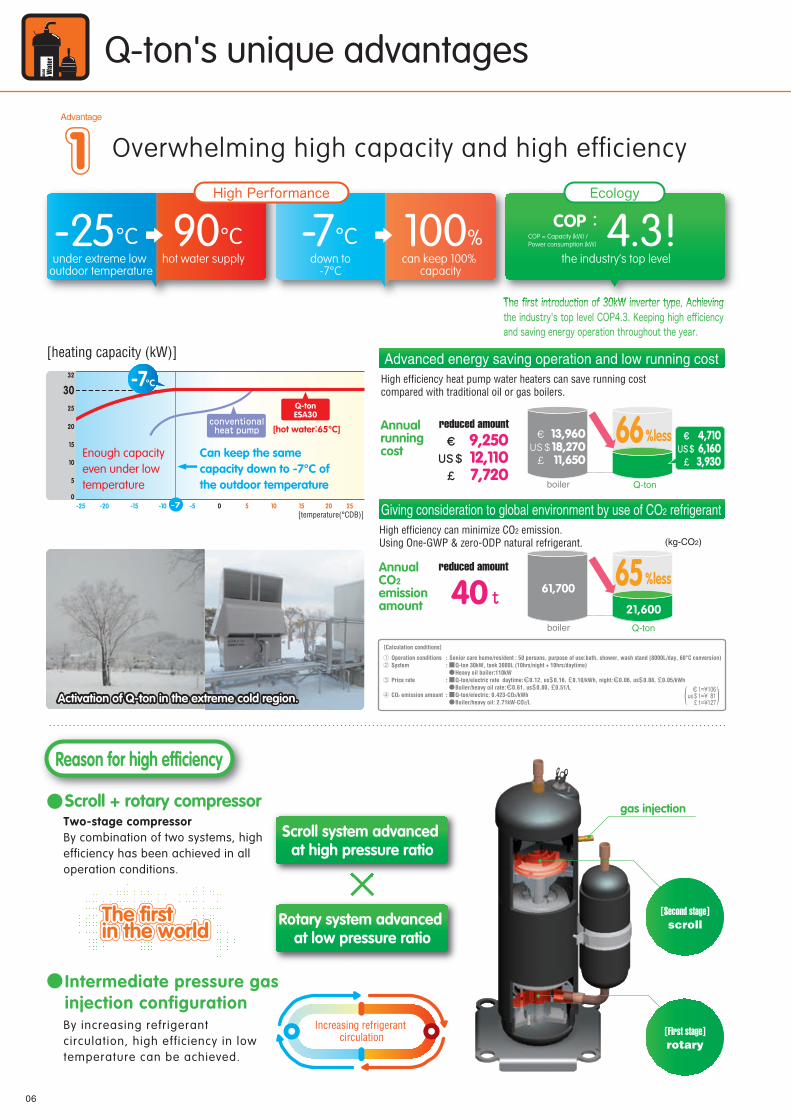
3032 High efficiency heat pump water heaters can save running cost
compared with traditional oil or gas boilers.
Advanced energy saving operation and low running cost
Q-tonboiler
16units with only one remote control.Max connection :
Q-ton's unique advantages
Overwhelming high capacity and high efficiency
Q-ton can be connected up to 16 units.
-25°C 90°Cunder extreme low
outdoor temperaturehot water supply
-7°C 100%down to
-7°Ccan keep 100%
capacity
The first introduction of 30kW inverter type, Achieving the industry's top level COP4.3. Keeping high efficiency and saving energy operation throughout the year.
Advantage
333
Advantage
111 Easy operationAdvantage
222
Annual running cost
Irrespective of any setting operation, this operation will keep on filling up hot water in a tank (100%).
You can check transition of hot water storage amount at a glance.
reduced amount 66%less
Schedule setting
As up to 480 kW capacity is possible by connecting 16 units of 30kW capacity, you can get enough hot water supply for any requirements. In case of the same operation of all units, you can control the system with only one remote control.
Increasing refrigerant circulation
The first introduction of 30kW inverter type, Achieving The first introduction of 30kW inverter type, Achieving
Ecology
COP :4.3!High Performance
the industry’s top level
COP = Capacity (kW) / Power consumption (kW)
::
:
:
Senior care home/resident : 50 persons, purpose of use:bath, shower, wash stand (8000L/day, 60°C conversion) Q-ton 30kW, tank 3000L (10hrs/night + 10hrs/daytime) Heavy oil boiler:110kW Q-ton/electric rate daytime: 0.12, us 0.16, 0.10/kWh, night: 0.06, us 0.08, 0.05/kWh Boiler/heavy oil rate: 0.61, us 0.80, 0.51/L Q-ton/electric: 0.423-CO2/kWh Boiler/heavy oil: 2.71kW-CO2/L
Operation conditionsSystem
Price rate
CO2 emission amount
[Calculation conditions]
Advanced touch screen panel with full dot Liquid Crystal display
User friendly•LCD panel with light tap operation
introduced as the industry's first
•Simple interface with only three buttons
High level of visibility•Big LCD with 3.8 inch full dot display
•Back light function
Setting of schedule such as weekly operation pattern , day off (for a Maximum one year) and peak-cut timer can be set easily.
RC-Q1E
operation to fill upHigh efficiency can minimize CO2 emission.Using One-GWP & zero-ODP natural refrigerant.
Giving consideration to global environment by use of CO2 refrigerant
Annual CO2 emission amount
Q-tonboiler
21,600
61,700
(kg-CO2)
reduced amount
40
REMOTE CONTROL
Activation of Q-ton in the extreme cold region.Activation of Q-ton in the extreme cold region.
gas injection
[First stage]rotary
[Second stage]scroll
Two-stage compressorBy combination of two systems, high efficiency has been achieved in all operation conditions.
Scroll + rotary compressor
Reason for high efficiency
The first in the worldThe first in the worldThe first in the world
Scroll system advanced at high pressure ratio
Rotary system advanced at low pressure ratio
€US$£
9,25012,1107,720
€US$£
13,96018,27011,650
€US$£
4,7106,1603,930
65%less
€1=¥106us$1=¥ 81£ 1=¥127( )

By increasing refrigerant circulation, high eff iciency in low temperature can be achieved.
Intermediate pressure gas injection configuration
0706
[temperature(°CDB)]
[heating capacity (kW)]
[hot water:65°C]
Enough capacity even under low temperature
2515 20-25 -20 5 10-15 -10 -5 0
-7°C
Q-tonESA30
conventionalheat pump
-7
Can keep the same capacity down to -7°C of the outdoor temperature5
0
10
15
20
25
3032 High efficiency heat pump water heaters can save running cost
compared with traditional oil or gas boilers.
Advanced energy saving operation and low running cost
Q-tonboiler
16units with only one remote control.Max connection :
Q-ton's unique advantages
Overwhelming high capacity and high efficiency
Q-ton can be connected up to 16 units.
-25°C 90°Cunder extreme low
outdoor temperaturehot water supply
-7°C 100%down to
-7°Ccan keep 100%
capacity
The first introduction of 30kW inverter type, Achieving the industry's top level COP4.3. Keeping high efficiency and saving energy operation throughout the year.
Advantage
333
Advantage
111 Easy operationAdvantage
222
Annual running cost
Irrespective of any setting operation, this operation will keep on filling up hot water in a tank (100%).
You can check transition of hot water storage amount at a glance.
reduced amount 66%less
Schedule setting
As up to 480 kW capacity is possible by connecting 16 units of 30kW capacity, you can get enough hot water supply for any requirements. In case of the same operation of all units, you can control the system with only one remote control.
Increasing refrigerant circulation
Ecology
COP :4.3!High Performance
the industry’s top level
COP = Capacity (kW) / Power consumption (kW)
::
:
:
Senior care home/resident : 50 persons, purpose of use:bath, shower, wash stand (8000L/day, 60°C conversion) Q-ton 30kW, tank 3000L (10hrs/night + 10hrs/daytime) Heavy oil boiler:110kW Q-ton/electric rate daytime: 0.12, us 0.16, 0.10/kWh, night: 0.06, us 0.08, 0.05/kWh Boiler/heavy oil rate: 0.61, us 0.80, 0.51/L Q-ton/electric: 0.423-CO2/kWh Boiler/heavy oil: 2.71kW-CO2/L
Operation conditionsSystem
Price rate
CO2 emission amount
[Calculation conditions]
Advanced touch screen panel with full dot Liquid Crystal display
User friendly•LCD panel with light tap operation
introduced as the industry's first
•Simple interface with only three buttons
High level of visibility•Big LCD with 3.8 inch full dot display
•Back light function
Setting of schedule such as weekly operation pattern , day off (for a Maximum one year) and peak-cut timer can be set easily.
RC-Q1E
operation to fill upHigh efficiency can minimize CO2 emission.Using One-GWP & zero-ODP natural refrigerant.
Giving consideration to global environment by use of CO2 refrigerant
Annual CO2 emission amount
Q-tonboiler
21,600
61,700
(kg-CO2)
reduced amount
40
REMOTE CONTROL
Activation of Q-ton in the extreme cold region.Activation of Q-ton in the extreme cold region.
gas injection
[First stage]rotary
[Second stage]scroll
Two-stage compressorBy combination of two systems, high efficiency has been achieved in all operation conditions.
Scroll + rotary compressor
Reason for high efficiency
The first in the worldThe first in the worldThe first in the world
Scroll system advanced at high pressure ratio
Rotary system advanced at low pressure ratio
€US$£
9,25012,1107,720
€US$£
13,96018,27011,650
€US$£
4,7106,1603,930
65%less
€1=¥106us$1=¥ 81£ 1=¥127( )

CO2
refrigerant circulation
compressor
expansion valve circulation pump
Unventedcylinder
Unventedcylinder
Unventedcylinder
Heat pump unitUnvented hot water storage cylinder
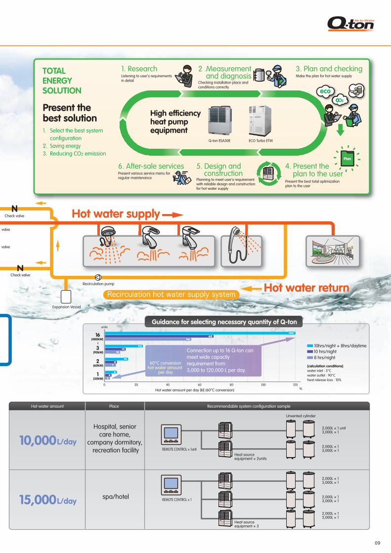
Hot water amount Place Recommendable system configuration sample
Recovering heat energy from the air
Hot water supply
0908
Hot water supply system
The world's first two-stage compressorScroll + Rotary compressor
High efficiency operation
Ecology and comfortable hot water supply system
REMOTE CONTROL
Unvented cylinder
3,000 L/day
4,000 L/day
5,000 L/day
REMOTE CONTROL × 1unit Heat source equipment × 1unit
REMOTE CONTROL × 1 Heat source equipment × 1
2,000L × 13,000L × 1
3,000L × 1 unit
REMOTE CONTROL × 1 Heat source equipment × 1
2,000L × 2
Big restaurant
Supply center of meal
Wedding venue
Hot water amount Place Recommendable system configuration sample
10,000L/day
15,000L/day
Heat source equipment × 3
REMOTE CONTROL × 12,000L × 13,000L × 1
2,000L × 13,000L × 1
2,000L × 13,000L × 1
spa/hotel
Hospital, senior care home,
company dormitory, recreation facility
Heat source equipment × 2units
REMOTE CONTROL × 1unit2,000L × 13,000L × 1
2,000L × 1 unit3,000L × 1
6,000 L/day REMOTE CONTROL × 1 Heat source equipment × 1
3,000L × 2School/company
lunch center
Mixing valve
Check valve
Check valve
Check valve
Recirculation pump
Expansion Vessel
Check valve
Hot water amount per day [kl] (60°C conversion)
1(30kW)
2(60kW)
3(90kW)
16
~(480kW)
0 20
units
40 60 80 100 120kL
[calculation conditions]water inlet : 5°Cwater outlet : 90°Cheat release loss : 10%
8 hrs/night10 hrs/night10hrs/night + 8hrs/daytime
120120
2323
68685454
1010
77
33
1313
44
881515
88
Connection up to 16 Q-ton can meet wide capacity requirement from 3,000 to 120,000 L per day.
60°C conversionhot water amount
per day
5. Design and construction
6. After-sale services
ECO Turbo ETWQ-ton ESA30E
High efficiency heat pump equipment
2 .Measurement and diagnosis
1. ResearchListening to user's requirements in detail Checking installation place and
conditions correctly
Planning to meet user's requirement with reliable design and construction for hot water supply
Present various service menu for regular maintenance
Present the best solution1.
2.3.
Select the best system configurationSaving energyReducing CO2 emission
Water supply
Guidance for selecting necessary quantity of Q-ton
System configuration guide
Water supply
storage
TOTAL ENERGY SOLUTION
4. Present the plan to the user
3. Plan and checkingMake the plan for hot water supply
Present the best total optimization plan to the user
Plan
CO2
eco
REMOTE CONTROL
Ecology and comfortable hot water supply system
heat exchanger for air
heat exchanger for heating water
Unvented cylinder
Unvented cylinder
Unvented cylinder
Starting an operation by a simple tap on button
Hot water returnRecirculation hot water supply system
CO2
refrigerant circulation
compressor
expansion valve circulation pump
Unventedcylinder
Unventedcylinder
Unventedcylinder
Heat pump unitUnvented hot water storage cylinder
Hot water amount Place Recommendable system configuration sample
Recovering heat energy from the air
Hot water supply
0908
Hot water supply system
The world's first two-stage compressorScroll + Rotary compressor
High efficiency operation
Ecology and comfortable hot water supply system
REMOTE CONTROL
Unvented cylinder
3,000 L/day
4,000 L/day
5,000 L/day
REMOTE CONTROL × 1unit Heat source equipment × 1unit
REMOTE CONTROL × 1 Heat source equipment × 1
2,000L × 13,000L × 1
3,000L × 1 unit
REMOTE CONTROL × 1 Heat source equipment × 1
2,000L × 2
Big restaurant
Supply center of meal
Wedding venue
Hot water amount Place Recommendable system configuration sample
10,000L/day
15,000L/day
Heat source equipment × 3
REMOTE CONTROL × 12,000L × 13,000L × 1
2,000L × 13,000L × 1
2,000L × 13,000L × 1
spa/hotel
Hospital, senior care home,
company dormitory, recreation facility
Heat source equipment × 2units
REMOTE CONTROL × 1unit2,000L × 13,000L × 1
2,000L × 1 unit3,000L × 1
6,000 L/day REMOTE CONTROL × 1 Heat source equipment × 1
3,000L × 2School/company
lunch center
Mixing valve
Check valve
Check valve
Check valve
Recirculation pump
Expansion Vessel
Check valve
Hot water amount per day [kl] (60°C conversion)
1(30kW)
2(60kW)
3(90kW)
16
~(480kW)
0 20
units
40 60 80 100 120kL
[calculation conditions]water inlet : 5°Cwater outlet : 90°Cheat release loss : 10%
8 hrs/night10 hrs/night10hrs/night + 8hrs/daytime
120120
2323
68685454
1010
77
33
1313
44
881515
88
Connection up to 16 Q-ton can meet wide capacity requirement from 3,000 to 120,000 L per day.
60°C conversionhot water amount
per day
5. Design and construction
6. After-sale services
ECO Turbo ETWQ-ton ESA30E
High efficiency heat pump equipment
2 .Measurement and diagnosis
1. ResearchListening to user's requirements in detail Checking installation place and
conditions correctly
Planning to meet user's requirement with reliable design and construction for hot water supply
Present various service menu for regular maintenance
Present the best solution1.
2.3.
Select the best system configurationSaving energyReducing CO2 emission
Water supply
Guidance for selecting necessary quantity of Q-ton
System configuration guide
Water supply
storage
TOTAL ENERGY SOLUTION
4. Present the plan to the user
3. Plan and checkingMake the plan for hot water supply
Present the best total optimization plan to the user
Plan
CO2CCOC
eco
heat exchanger for air
heat exchanger for heating water
Unvented cylinderUnvented cylinder
Starting an operation by a simple tap on button
Hot water returnRecirculation hot water supply system

10 11
Installation samples in Japan
There are a number of ways to conserve the environment including introducing new energy resources and promoting carbon offsets. Introducing a heat pump is of these means. As i t was recognized as a “Vi l lage working to reduce carbon emissions” project that was el igible for subsidies from Hokkaido, four hotels introduced heat pumps at the same time.
Yakata has comfortable bathing facilities for day-service users.As a precaution, a back-up system is equipped to provide hot water at all times.
Widely known hot spring resort where the G8 Hokkaido Toyako Summit 2008 was held.Hot water at 90 degrees C is available even when the temperature is – 25 degrees C.
Compared to combustion-base water heaters (boilers), this system can reduce running costs by approximately 66% per year.
Rikyu Senriyama takes advantage of an all-electric system including hot-water supply and air conditioning.A 24-hour remote monitoring system provides them with peace of mind.
Taking energy-saving, efficiency and usability into consideration, we offered a proposal, including for air conditioning. A heat pump was selected to supply hot water to reflect our consideration for the global environment and running costs. This institution expects to use 16,000 l of hot water per day for bathrooms, washrooms, the kitchen and other areas. With the Remote Control, you can easily set the amount of hot water to use and to reserve. This system is an effective way to save energy. Also, by adopting a 24-hour remote monitoring system, they have been using the system with peace of mind.
Switched from an electrical water heater to “Q-ton”, Co2 heat pump water heater for business purposes.A steady supply of hot water at 80 degrees C is ensured even when the temperature is -15 degrees C.
Increasing the amount of hot water required and reducing the temperature of hot water during winter time is now no longer a problem.
By utilizing a feed water heating method, hot water is supplied efficiently, subsequently saving energy.
An electrical water heater was used in the day service building from the time it was built, but due to the increase in hot water usage and aging, many problems developed including the temperature of hot water dropping during winter. As a result, they decided to introduce Q-ton. In December 2011, two Q-ton ESA30-25 units and an MHQT8000KM open tank were installed. The system provided sufficient hot water at high temperatures, and users of day services subsequently could enjoy more satisfaction when having a bath. Q-ton has been adopted for a new living quarters that is scheduled to open soon.
Highly efficient when heating feed water.Saving energy by using Q-ton and the existing boiler side by side.
•Steady performance in cold weather regions•Defrosting function at low temperatures/high humidity•Countermeasure against skyrocketing price of crude oilIn the past, this company used heavy oil as a fuel to generate steam in a boiler and using the steam to heat the dry furnace and chemicals as well as for air conditioning. The amount of heat per unit price is greater when using a heat pump when taking the rising price of crude oi l into account. Also, a heat pump emits less carbon dioxide. These were the decisive factors.
Seiseikai Medical Corporation Yakata Tower for the Elderly
Osaka PrefectureOsaka City
01 Adult Day Care CentersHokkaido
04
Annual running costs have been reduced by 66%.
Two advantages of introducing this product.Q-ton works with both a sealed tank and an open tank. You can select the best system for your usage environment even when you need to change the design urgently. By systematizing the system with one thermal source, we make back-up operation possible so that day-service users will not be inconvenienced.
We offer proposals from the comprehensive viewpoint of energy-saving, efficiency and usability, including air conditioning.
Q-ton plays an active role in the all-electric facility. Plenty of hot water and satisfaction with the Remote Control.
Considering the global environment and the safety of residents, this institution introduced an all-electric system and adopted EcoCute for business purposes as a thermal source for heating water. Hot water supplied by Q-ton is used in bathrooms and showers on each floor and on the ground floor for washing dishes in the kitchen. In the small-scale Intensive Care Home for the Elderly where up to 29 seniors live, one unit of Q-ton can supply all the hot water. The staff are happy with the system because it provides a stable source of hot water, saves energy, and is safe and easy to maintain.
One Q-ton unit can supply all the hot water required.
Lake Toya Hot Spring •Hokkai Hotel•Hotel Grand Toya
•Toya Kanko Hotel•Toya Sansui Hotel
Rokushinkai Social Welfare Corporation Rikyu Senriyama Welfare Facility Complex
Osaka PrefectureSuita City
02Intensive Care Home for the Elderly Fukushima Prefecture
05 Intensive Care Home for the Elderly
Inawashiro Fukushikai Social Welfare CorporationInawashiro Home
Jesus Band Social Welfare CorporationSmall-scale Intensive Care Home for the ElderlyShin-ai Kumochi Home
Hyogo Prefecture
03Intensive Care Home for the Elderly Toyama Prefecture
06 Factory / manufacturing facility NEC ToppanCircuit Solutions, Inc.
04
05
02
01
03
06
1312
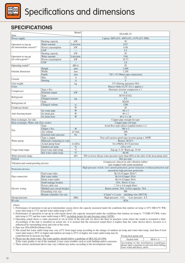
Model : ESA30E
DimensionsSPECIFICATIONS
Specifications and dimensions
Connection of the water piping (water inlet, hot water outlet, drain port) should be arranged on site.The thickness of the lagging material for the water piping shall be 30 mm, and the racking cover used shall have an outer diameter of 100 mm or less, and an outer circumference of 315 mm or less.If the outer diameter of the racking cover is 100 mm or more, or the outer circumference is 315 mm or more, it will not be possible to remove the service panel after the racking is installed.The drain port should be open to the atmosphere. Do not c lose the port with a valve, etc.
ModelItem ESA30E-25
Power supply 3-phase 380V±5%, 400V±5%, 415V±5% 50Hz
Operation to top up(In intermediate season)*1
Heating capacity kW 30Water amount Liter/min 8.97Power consumption kW 6.98COP — 4.3
Operation to top up(In cold region)*2
Heating capacity kW 30Water amount Liter/min 5.06Power consumption kW 10.73COP — 2.8
Operating sound*3 dB(A) 58
Outside dimensionHeight mm 1,690Width mm 1,350Depth mm 720 + 35 (Water pipe connection)
Current Max A 21Starting A 5
Unit weight kg 375 (During operation 385)Color Stucco white (4.2Y7.5/1.1 approx.)
Compressor Type x Pcs Hermetic inverter compressor × 1Nominal output kW 6.4
Refrigerant Type R744 (CO2)Charged amount kg 8.5
Refrigerant oil Type MA68Charged volume cc 1200
Crankcase heater W 20
Anti-freezing heaterfor water pipe W 48 × 3for drain pan W 40 × 2for drain hose W 40 × 2 + 48
Heat exchanger, Air side Copper pipe straight fi n typeHeat exchanger, Water side (Gas cooler) Copper pipe coil type
Fan
Type Axial fl ow type (direct coupled motor) × 2Output x Pcs W 386 × 2Air volume m3/min 260External static pressure Pa 50
Water pumpType x output Non-self-suction spiral type inverter pump × 100WMaterials contacting to water Bronze, SCS13Actual pump head m (kPa) 5m (49kPa) @17Liter/min
Usage temp rangeOutdoor air temp °C -25 to +43Feed water inlet temp °C Top up: 5-35, Warm up: 35-65Hot water outlet temp °C 60-90
Water pressure range kPa 500 or lower (Keep water pressure more than 0kPa at the inlet of the heat pump unit)Defrost Hot gas type
Vibration and sound proofi ng devices Compressor: placed on anti-vibration rubberand wrapped with sound insulation
Protection devices High pressure switch, over current protection, power transistor overheat protection andanomalous high pressure protection
Pipe connectionFeed water inlet Rc3/4 (Copper 20A)*4
Hot water outlet Rc3/4 (Copper 20A)Drain water outlet Rc3/4 (Copper 20A)
Electric wiring
Earth leakage breaker 30A, 30mA, 0.1secPower cable size 14 × 4 (Length 40m)Molded-case circuit breaker Rated current: 30A, switch capacity: 30AGrounding wire size M6Remote controller wire size 0.3mm2 × 2 cores shielding wire (MVVS)
Design pressure MPa High pressure : 14.0, Low pressure : 8.5IP code IP24
(Note)1. Performance of operation to top up in intermediate season shows the capacity measured under the conditions that outdoor air temp is 16°C DB/12°C WB,
water inlet temp is 17°C and hot water outlet temp is 65°C.2. Performance of operation to top up in cold region shows the capacity measured under the conditions that outdoor air temp is -7°CDB/-8°CWB, water
inlet temp is 5°C and hot water outlet temp is 90°C excluding heater for anti-freezing water (345W).3. Operating sound shows a value measured at 1m in front of the unit and 1m above the fl oor in anechoic room where the sound is resonated a little.
Accordingly if the unit is installed on actual site, it is normal that the measured sound there is higher than the value shown above, because it is infl uenced by surrounding noise and echo in the room.
4. Pipe size 20A=DN20=20mm=3/4in5. The actual hot water outlet temp may vary ±3°C from target temp according to the change of outdoor air temp and water inlet temp. And then if feed
water inlet temp is 30°C or higher and outdoor air temp is 25°C or higher, hot water outlet temp may be controlled not to increase too high.6. Please use the clean water. The water quality should follow a guideline of JRA-GL.02:1994.
If the water quality is out of the standard, it may cause troubles such as scale buildup and/or corrosion.7. These articles mentioned above may vary without any notice according to the development status.
Fixing heat pump unitAnchor bolt M10 × 4
According to the installation conditions, please take a measure to prevent from falling, cross wind and heavy snow.

1312
Model : ESA30E
DimensionsSPECIFICATIONS
Specifications and dimensions
Connection of the water piping (water inlet, hot water outlet, drain port) should be arranged on site.The thickness of the lagging material for the water piping shall be 30 mm, and the racking cover used shall have an outer diameter of 100 mm or less, and an outer circumference of 315 mm or less.If the outer diameter of the racking cover is 100 mm or more, or the outer circumference is 315 mm or more, it will not be possible to remove the service panel after the racking is installed.The drain port should be open to the atmosphere. Do not c lose the port with a valve, etc.

1514
Installation work
Wirings for sensors forunvented cylinder
② Remote control
④ Wirings for CWFV3
Air purge valve
3-way value, CWFV3
Hot water temp
Feed water temp
GV
GV
GV
FJ
GVT P
FJGV
FJYS
Drain
Drain
Clean water tank
① ESA30 ③ Unvented cylinders
T P
CV
GV:Gate ValveCV:Check valveFJ:Flexible jointYS:Strainer (Y-type)
RT P
⑥ Clean water supply Pressure pump
⑭ Expansion
⑩ Air purge valve
Vessel
⑪ Relief valve
⑧ Stop valve. CWFV5
⑥ Hot Waler temp sensor
⑨ Anli-treezing healer
⑫ Insulation
⑨
⑨
for unvented cylinderfor water pipings
⑤ Pressure reducing valve
Part name Model General description① Heat pump unit ESA30E-25 For outdoor air temp -25°C
② Remote control for heat pump water heater (Option part) RC-Q1E For setting hot water amount and setting hot water temp.
③ Unvented cylinder(Locally procured) — Refer to the specifications of unvented cylinder mentioned on next page.
④ Wiring kit for unvented cylinder(Option part)
MTH-Q1E (20m length of wire)
orMTH-Q2E
(10m length of wire)
For connecting heat pump unit with unvented cylinder• Connect to the water temp sensor of unvented cylinder• Connect to the 3-way valve for switching to anti-freezing circuit and control it
⑤ Pressure reducing valve(Locally procured ) —
Connecting pipe size≧32ASetting pressure is to be set lower than 500kPa at the inlet of the heat pump unit and lower than the design pressure of the cylinders. Also please be considered that the head difference of the heat pump unit and the cylinders and the tolerance of the relief valve (especially lower side)
⑥ Hot water temp sensor(Option part) MTH-Q3E Mounting or pasting on the unvented cylinder for detecting hot water temp in the cylinder. 1.25m length x 9
⑦ 3-way valve, CWFV3 (Option part) MTH-Q4E For switching to anti-freezing circuit (wiring length 0.7m, AC200V, 50mA)
⑧ Stop valve of hot water supply, CWFV5 (Option part) MTH-Q5E If the multiple heat pump water heaters are connected, it is necessary to use at the hot water supply line. (wiring
length 0.7m, AC200V, 50mA)
⑨ Anti-freezing water heater(Locally procured) — When outdoor air temp becomes below 0°C, be sure to install this heater on the water pipe (10W/m)
⑩ Air purge valve(Locally procured) — For purging the air in the hot water system which is generated during heating up the water in the unit or is
mixed in the system when feeding water. Each valve is required for each cylinder.
⑪ Relief valve (Locally procured) —For preventing from increasing pressure in the system during heating up the water.Working pressure is to be set lower than 500kPa at the inlet of the heat pump unit and lower than the design pressure of the cylinders. Also please be considered that the head difference of the heat pump unit and the cylinders and the tolerance of the relief valve
⑫ Insulation (Locally procured) —Heat resistance≧120°C• For the cylinder shell: 50mm or thicker glass wool whose density is 16kg/m3.• For the cylinder end plate: 50mm or thicker glass wool whose density is 24kg/m3.• For the water piping: 30mm or thicker glass wool whose density is 48kg/m3.
⑬ Clean water supply pressure pump (Locally procured) — Apply pressure to the primary side of the pressure reducing valve, which is more than a valve of the secondary
side.⑭ Expansion Vessel (Locally procured) — —
2. Specifications of unvented hot water storage cylinder for connecting to ESA30EPlease arrange and procure a new unvented cylinder with following specifications for connecting to ESA30E.* If connecting ESA30 to the existing cylinder, the hot water temp and amount in the cylinder cannot be detected correctly. In such case, please
consult with our distributor.In some case, preliminary survey on site may be required before installation
Specifications of unvented cylinder• For commercial use
The cylinder is installed indoors, not outdoors • It should be unvented hot water storage cylinder, not open cylinder.• The minimum capacity is 500liter. If increasing capacity, please use bigger size cylinder or several cylinders in parallel.• The maximum capacity is 4000liter. (only as a guide)
The cylinder capacity may vary according to feed water inlet temp, hot water outlet temp and operation hours in the night.25837 x Operation hour in the night/ (Hot water outlet temp- feed water inlet temp) =available hot water supply volume (Liter). However, there is dead volume, where the cold water is always filled in, at the bottom of cylinder to which the feed water line is connected. Therefore please select the cylinder volume in consideration of available hot water supply volume and dead volume.
• Design pressure Design pressure is 0.5MPa or higher.The design pressure of ESA30E is 0.5MPa. Even if the design pressure of the cylinder is 0.5MPa or higher, the maximum water pressure applied to the cylinder actually shall be less than 0.5MPa. And please decide the usage pressure in consideration of allowance and setting value of relief valve.Even if the actual pressure applied to the cylinder is 0.5MPa, the cylinder can be used, but the minimum pressure shall be 0.1 to 0.2MPa or higher. If the pressure becomes lower than the minimum pressure, water volume becomes decreasing.
1. Standard hot water supply system diagram (for unvented cylinder)
Component list of hot water supply system (for unvented cylinder)

1514
Installation work
Wirings for sensors forunvented cylinder
② Remote control
④ Wirings for CWFV3
Air purge valve
3-way value, CWFV3
Hot water temp
Feed water temp
GV
GV
GV
FJ
GVT P
FJGV
FJYS
Drain
Drain
Clean water tank
① ESA30 ③ Unvented cylinders
T P
CV
GV:Gate ValveCV:Check valveFJ:Flexible jointYS:Strainer (Y-type)
RT P
⑥ Clean water supply Pressure pump
⑭ Expansion
⑩ Air purge valve
Vessel
⑪ Relief valve
⑧ Stop valve. CWFV5
⑥ Hot Waler temp sensor
⑨ Anli-treezing healer
⑫ Insulation
⑨
⑨
for unvented cylinderfor water pipings
⑤ Pressure reducing valve
• Pipe connection portCylinder has one or more pipe connection ports at the top. The size of port shall be 32A or bigger.If it is smaller than 32A, it is difficult to detect the hot water temp and hot water amount in the cylinder properly. And when discharging the hot water from the cylinder, the outlet flow volume may be restricted.Cylinder has 2 or more pipe connection ports at the bottom. The size of one port shall be 32A and the other port shall be 20A. * 32A=DN32=32mm=1-1/4in 20A=DN20=20mm=3/4in
• Specifications of inner cylinderIn order to ensure the temp boundary layer as minimum as possible when hot water and feed water flow into the cylinder, the cylinder shall have buffer plates built-in. Please consult with our distributor.
• MaterialSUS444 or SUS316 (with consideration for stress corrosion cracking resistance)If using the other material than the specified one, hot water temp and hot water amount in the cylinder may not be detected correctly.Please consult with our distributor.
• Heat resisting temperature90°CThe maximum hot water outlet temp of ESA30E is 90°C. If the heat resisting temp of the cylinder is lower than 90°C. Be sure to reduce the hot water outlet setting temp in order to meet the specifications of the cylinder.If using the cylinder at the higher water outlet temp than the heat resisting temp of the cylinder, it may have break of the cylinder or leakage of hot water.
• Applying hot water temp sensors on the cylinderIn order to judge the hot water temp and amount in the cylinder, the temp sensors shall be mounted or pasted on the cylinder.If pasting the temp sensors, they shall be pasted with aluminum adhesive tape whose heat resisting temp is 90°C or higher.If mounting the temp sensors, the insertion holes with ø7mm or bigger in size and 20mm or deeper in depth are required on the cylinder.MHI’s genuine temp sensor, MTH-Q3E (option part), shall be used.3 to 9 sets of temp sensors shall be applied to the cylinder.In order to detect the hot water amount by 10% intervals, 9 sets of temp sensors shall be applied to the cylinder. If reducing the number of temp sensor, the hot water amount cannot be detected properly.Ex) In case of applying 3 sensors, heat pump unit can detect only 20%, 60% and 100% of HW amount. (Please refer to following table) Therefore, even though 80% of HW amount is set with schedule setting, the HP unit cannot stop at storing 80% of HW amount and it still keeps on operating until storing 100% of HW amount.And if 30% of HW amount is set for the operating to top up, HP unit cannot start operation to top up until HW amount decreases to 20%.Accordingly, we recommend to apply 9 sensors to the cylinder for precise control.The positions to apply the temp sensors on the cylinder are depended on the number of sensors and sensors should be applied to the designated positions on the cylinder. (See page 85 and 86 for detail)According to the following table, please check the number of sensor and apply each sensor to the designated position of hot water amount % according to the sensor No. Please refer to page 84 “7-1 Applying method of hot water temp sensors on the cylinder” for details.
The position to apply temp sensor according to the hot water amount %
Number of sensors to applySensor No. 3pcs 4pcs 5pcs 6pcs 7pcs 8pcs 9pcs*1
Tht-1 20% 20% 20% 10% 20% 10% 10%Tht-2 60% 50% 40% 30% 30% 20% 20%Tht-3 100%*2 75% 60% 40% 40% 30% 30%Tht-4 100%*2 80% 60% 50% 50% 40%Tht-5 100%*2 70% 65% 60% 50%Tht-6 100%*2 80% 70% 60%Tht-7 100%*2 80% 70%Tht-8 100%*2 80%Tht-9 100%*2
*1 Recommendable number of sensors is 9pcs. If the number of sensors is less than 9pcs, the hot water amount cannot be detected correctly.*2 The sensor which detects 100% of HW amount shall be applied to the position within the range of sensitive volume with consideration of dead volume which is 10% of total volume of cylinder.
Recommendable

1716
ItemCyclic water
(60°C< 90°C)Makeup water
Standard items
pH (25°C) – 7.0 – 8.0 7.0 – 8.0
Electric conductivity (25°C) mS/m 30 30
Chloride ion mgCl– /L 30 30
Sulphate ion mgSO23
– /L 30 30
Acid consumption (pH4.8) mgCaCO3/L 50 50
Sulphide ion/Acid consumption – 0.5 0.5
Total hardness mgCaCO3/L 70 70
Calcium hardness mgCaCO3/L 50 50
Ionic silica mgSiO2/L 20 20
Reference items
Iron mgFe/L 0.1 0.3
Copper mgCu/L 0.1 0.1
Sulphide ion mgS2–/L Not detected Not detected
Ammonium ion mgNH4+/L 0.1 0.1
Residual chlorine mgCl /L 0.1 0.3
Free carbon mgCO2/L 0.4 4.0
Stability index – –
Makeup water and cyclic water shall be the water within the range of water quality criteria mentioned below.
If water quality is out of the range of criteria, it may cause a trouble such as scale adhesion and corrosion.
(3) Drain piping work
(4) Water quality criteria
• At a place where the drain water from the heat pump unit becomes a problem, please install drain piping by using drain elbow, drain grommet (locally prepared)
• The end of drain pipe shall be open the air.• When draining from drain pipe of unvented cylinder, open the pressure relief valve (raise the lever), and after the end of drain, close
the valve (let down the lever)
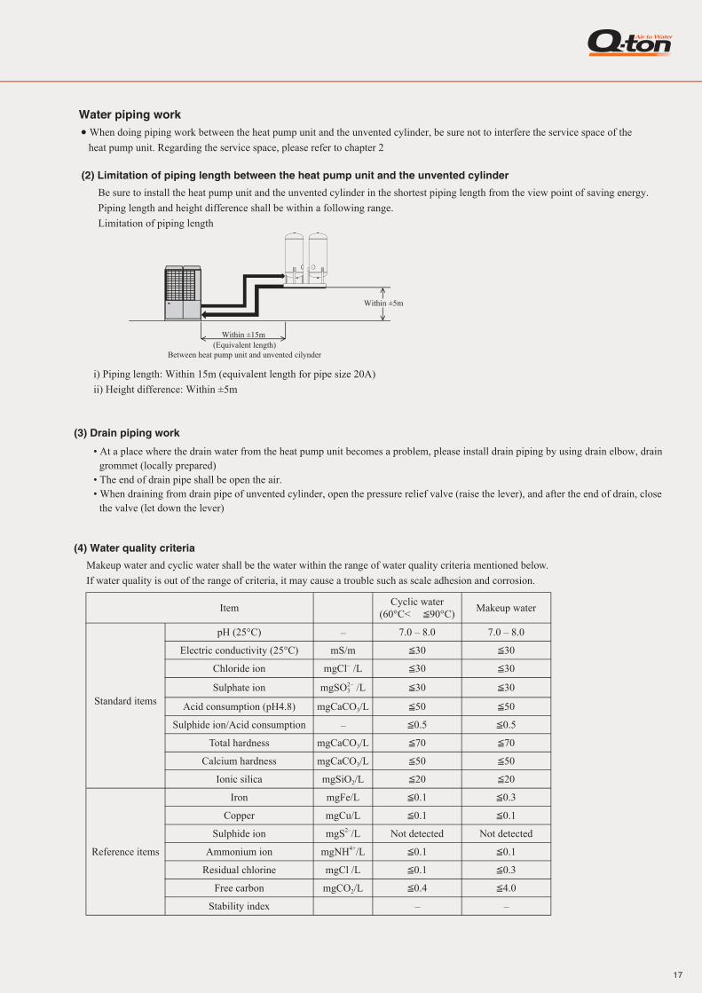
Water piping work• When doing piping work between the heat pump unit and the unvented cylinder, be sure not to interfere the service space of the
heat pump unit. Regarding the service space, please refer to chapter 2
(2) Limitation of piping length between the heat pump unit and the unvented cylinder
Be sure to install the heat pump unit and the unvented cylinder in the shortest piping length from the view point of saving energy.
Piping length and height difference shall be within a following range.
Limitation of piping length
i) Piping length: Within 15m (equivalent length for pipe size 20A)
ii) Height difference: Within ±5m
Within ±5m
Within ±15m(Equivalent length)
Between heat pump unit and unvented cilynder②
Heat pump unit
③①
③④②①
④
⑦
⑨ ⑪
⑨⑩
⑤
⑤⑥
⑧
Structure of water piping
shows the flow direction of water
T P
T P
• InsulationInsulation must be required in order to keep hot water temp stored in the cylinder.• Shell
Material: Glass woolDensity: 16kg/m3
Thickness: 50mm or more• End plate
Material: Glass woolDensity: 24kg/m3
Thickness: 50mm or more• Carry in, Installation and Service & maintenance space
It depends on the installation manual of the cylinder procured.
(i) Key consideration for water pipingPlease consider following point when designing and installing. (Description of ① _⑪ in above figure)① Union joint Be sure to fit it in order to enable the unit replacement easily.② Thermometer Be sure to equip it for capacity check and operation monitoring③ Water pressure gauge You had better equip it for checking operation status. ④ Valve Be sure to fit it for servicing such as cleaning heat exchanger and/or replacing unit and etc.⑤ Flexible joint Be sure to fit it for preventing from transmittance of vibration⑥ Drain piping Be sure to make its descending slop as larger as possible and make the distance of its horizontal part as shorter as
possible in order to prevent the drain water from freezing.Moreover, in cold region, be sure to take a measure for anti-freezing drain water by equipping drain heater or like that.
⑦ Strainer Be sure to fit a strainer (60 mesh or more) at the inlet port of the unit to avoid intrusion of foreign matter into the unit.
⑧ Air purge valve Be sure to equip it to the place where air may accumulate in order to purge air in the water pipe.⑨ Water piping Water piping work shall be done by considering to purge air in the water pipe easily. Insulation work shall be
done sufficiently.⑩ Drain valve Be sure to equip it in order to drain off the water from the system at servicing.⑪ Check valve Be sure to equip it in order to prevent hot water from flowing back from the existing system connected or from
other heat pump water heaters connected in multiple system.(ii) Caution for corrosion① Water quality
It is important to check in advance whether the feed water and hot water have good quality.Be sure to use cyclic water and makeup water whose qualities are within the range of water quality criteria mentioned in Page 20.
② Foreign matter in waterIf solid matter such as sand and small stone and/or floating suspended solid such as corrosion product exist in water, the heat-transfer surface of heat exchanger is directly attacked by water flow, and corrosion may be created locally.In order to avoid such corrosion by these foreign matters, be sure to fit a cleanable strainer (60 mesh or higher) at the water inlet port of the unit to remove foreign matters.
③ Contact of different metalDepending on the type of metal, if different metals contact directly, corrosion may be generated at contact part.Refer to followings and in case of the combination of different metals to generate corrosion, take a measure not to generate corrosion by inserting a non-conductive material (non-metallic insulation flange and etc) between the metals or by other method
The combination not to generatecorrosion by contact of metals
④ Others1) Water pipe shall have no water leak and no air intrusion. Especially if air intrudes at suction side of pump, pump performance be-
comes decreasing and it may cause generation of noise2) Be sure to take into consideration for water pipe not to freeze at stopping operation in winter
3. Water piping work(1) Outline of water piping
① Stainless steel (SUS304, SUS316)② Bronze③ Copper
1716
ItemCyclic water
(60°C< 90°C)Makeup water
Standard items
pH (25°C) – 7.0 – 8.0 7.0 – 8.0
Electric conductivity (25°C) mS/m 30 30
Chloride ion mgCl– /L 30 30
Sulphate ion mgSO23
– /L 30 30
Acid consumption (pH4.8) mgCaCO3/L 50 50
Sulphide ion/Acid consumption – 0.5 0.5
Total hardness mgCaCO3/L 70 70
Calcium hardness mgCaCO3/L 50 50
Ionic silica mgSiO2/L 20 20
Reference items
Iron mgFe/L 0.1 0.3
Copper mgCu/L 0.1 0.1
Sulphide ion mgS2–/L Not detected Not detected
Ammonium ion mgNH4+/L 0.1 0.1
Residual chlorine mgCl /L 0.1 0.3
Free carbon mgCO2/L 0.4 4.0
Stability index – –
Makeup water and cyclic water shall be the water within the range of water quality criteria mentioned below.
If water quality is out of the range of criteria, it may cause a trouble such as scale adhesion and corrosion.
(3) Drain piping work
(4) Water quality criteria
• At a place where the drain water from the heat pump unit becomes a problem, please install drain piping by using drain elbow, drain grommet (locally prepared)
• The end of drain pipe shall be open the air.• When draining from drain pipe of unvented cylinder, open the pressure relief valve (raise the lever), and after the end of drain, close
the valve (let down the lever)
Water piping work• When doing piping work between the heat pump unit and the unvented cylinder, be sure not to interfere the service space of the
heat pump unit. Regarding the service space, please refer to chapter 2
(2) Limitation of piping length between the heat pump unit and the unvented cylinder
Be sure to install the heat pump unit and the unvented cylinder in the shortest piping length from the view point of saving energy.
Piping length and height difference shall be within a following range.
Limitation of piping length
i) Piping length: Within 15m (equivalent length for pipe size 20A)
ii) Height difference: Within ±5m
Within ±5m
Within ±15m(Equivalent length)
Between heat pump unit and unvented cilynder②
Heat pump unit
③①
③④②①
④
⑦
⑨ ⑪
⑨⑩
⑤
⑤⑥
⑧
Structure of water piping
shows the flow direction of water
T P
T P

1918
4. Heat pump unit installation space (Service space)
L4
Air inlet Air inlet
L2
Air inlet
Air inlet
Service spacefor gas cooler & heat exchanger
L3
L1
Service spacefor compressor & controller
Wall height: H3
Wall height: H2 Wall height: H4
Wall height: H1
Installation space
Dimension 1 2
L1 800 800L2 10 10L3 800 800L4 100 500L5 100 500L6 100 500H1 1500 1500H2 No limit No limitH3 1000 1000H4 No limit No limit
Installation example
(1) Wiring system drawing
5. Electrical wiring workElectrical installation work must be performed by an electrical installation service provider qualified by a power provider of the country.
Electrical installation work must be executed according to the technical standards and other regulations applicable to electrical installa-
tions in the country.
Please install an earth leakage breaker without fail. The installation of an earth leakage breaker is compulsory in order to
prevent electric shocks or fire accidents.
(Since this heat pump unit employs inverter control, please use an impulse withstanding type one to prevent the earth leakage
breaker from false activation.+_
*1 In case of multiple master unit connected to a remote controller individually, CWFV5 is required for each master unit.
*2 If another master unit without remote controller is connected in the same system, the same wiring method as this should be done. (16 sets of master units are connectable at the maximum.)
TB
HEAT PUMP UNIT
TB2 TB1
5
3
CWFV3
648
TB
REMOTE CONTROLLER
4
Earth leakage breaker(Impulse withstanding)
Circuit breaker
Power supply: 3Ø380/400/415V±5% 50Hz
TB
HEAT PUMP UNIT
5
3
CWFV3
648
TB
REMOTE CONTROLLER
4
Earth leakage breaker(Impulse withstanding)
)
Circuit breaker
Power supply: 3Ø380/400/415V±5% 50Hz
TB
HEAT PUMP UNIT
CWFV T1-4 T5-6 T7-9
TB2 TB1
Connector
5
3
CWFV3
648
TB
4
Earth leakage breaker(Impulse withstanding)
)
Circuit breaker
Power supply: 3Ø380/400/415V±5% 50HzMaster unit 1 Master unit 2
CWFV5 CWFV5
33
CWFV5
3 *1
*2
CWFV T1-4 T5-6 T7-9
A B X Y L1 L2 L3 N
R
Connector
Terminal
Terminal
CWFV T1-4 T5-6 T7-9
R
Connector
A B X Y L1 L2 L3 N A B X Y L1 L3 NL2TB2 TB1
In case of Master unit 1 and 2
In case of Master unit only
(2) Connecting method of power cable
(a) Method for leading out cables • Cables can be led out through the front, right, left panel and bottom plate. • In wiring on installation site, cut off a half-blank (φ50 or elongate hole 40x80) cover for penetration of cables with nipper. • In case of a collective drain piping, please use the hole to lead out cables or pipe other than the hole on bottom plate. If the hole on bottom plate is used, be careful to apply adequate seal in order not to leak drain.
(b) Notabilia in connecting power cables • Connect the grounding wire before connecting power cable. When connecting a grounding
wire to a terminal block, use a grounding wire whose length is longer than the power ca-ble so that it may not be subject to tension.
• Do not turn on power until installation work is completed. Turn off power to the unit be-fore servicing the unit.
• Ensure that the unit is properly grounded. • Power cables must always be connected to the power cable terminal block and clamped
them outside the control box. • In connecting to the power cable terminal block, use a round -type crimped terminal. • If 2 cables connect to one terminal block, be sure to put the crimped terminals to back con-
nection. And in such case please place a thin cable on the thick cable as shown in the right figure • Use specified wires in wiring, and fasten them securely in such a manner that the terminal blocks are not subject to external force. • In tightening a screw of terminal block, be sure to use a correct-size screw driver.
Tightening a screw of terminal block with excessive torque force may break the screw. For the tightening torque of terminals, refer to the table shown at right. • When electrical installation work is completed, make sure that all electrical components in the control box have no loose connector cou-
pling or no loose terminal connection.
(c) Heat pump unit power supply specifications: 3-phase 380V/400V/415V±5% 50Hz
Please note ① Wiring procedure is determined by JEAC8001 (please adapt it to the regulations in effect in each country.) ② The wire length and cable size in above table show that within 2% of voltage drop. If the wire length exceeds the value shown in the
above table, review the cable size according to the regulations of the country. ③ If the earth leakage breaker is exclusive for ground fault protection, the circuit breaker is required additionally. For selecting the circuit breaker, please refer to the technical manual or ask our distributor.
(3) Connecting method of signal wire • The signal line is DC5V so that please do not connect single phase 220V/230V/240V of power cable to the signal line. In case to connect power cable, the fuse on the control PCB is blown. ① Please check that power cable is not connected to the signal line. ② Before turning on power supply, be sure to check resistance on the terminal block of signal line. If the measured resistance is 100Ω or lower, power line may touch to signal line. • Standard signal wire size is 0.75mm2 x 2 cores shielding wire (MVVS) • The both end of shielding wire shall be grounded.
• Remote control wiring • Standard remote control wire size is 0.3mm2 x 2 cores shielding wire (MVVS) • The both end of shielding wire shall be grounded. • If using 100m or longer wire, please use the wire size shown in below table.
Cable size for power source
(mm2)Wire length (m)
Earth leakage breaker (Grounding fault, overload,
short circuit protection)
Earth wire
Size (mm2) Screw type14 40 30A, 30mA, 0.1sec or shorter 14 M6
7mm or smaller
Length (m) Wire size100≦ <200 0.5mm2 x 2 cores shielding wire (MVVS)200≦ <300 0.75mm2 x 2 cores shielding wire (MVVS)300≦ <400 1.25mm2 x 2 cores shielding wire (MVVS)400≦ <600 2.0mm2 x 2 cores shielding wire (MVVS)
Round type climped terminal
Wiring
terminal block
climped terminalWire size: thin
Wire size: thick
tightening torque (N・m)
M4 Signal line terminal block 0.68-0.82
M6 grounding wire 2.50-3.00
M12 Power cable terminal block 22.05-26.46

ESA30E
Our Air Conditioning & Refrigeration Systems Headquarters is an ISO9001 approved factory for residential air conditioners and commercial-use air conditioners (including heat pumps).
ISO9001
BIWAJIMA PLANT Mitsubishi Heavy Industries, Ltd.
Air-conditioning & Refrigeration Systems HeadquartersCertified ISO 9001
Certificate number : JQA-0709
MITSUBISHI HEAVY INDUSTRIES-MAHAJAK AIR CONDITIONERS CO., LTD.
Certified ISO 9001Certificate Number : 04100 1998 0813
HB91-13HM01E-A-2 Oct. 2013(1B)R Because of our policy of continuous improvement, we reserve right to make changes in all specifications without notice.
Printed in Japan
MITSUBISHI HEAVY INDUSTRIES-MAHAJAK AIR CONDITIONERS CO.,LTD.
Certificate Number : 04104 1998 0813 E5
ISO 14001Certificate 04104 1998 0813 E5
Mitsubishi Heavy Industries, Ltd.Air-Conditioning & Refrigeration Systems Headquarters16-5, Konan 2-chome, Minato-ku, Tokyo, 108-8215 Japanhttp://www.mhi.co.jp
13HM01E-A-2
Commercial useHeat pump water heater
Ecological energyRecovering heat energy from the air
日本冷凍空調学会
技 術 賞(2012FY)