Embed Size (px)
Citation preview
www.gunt.de
ET 910 TRAINING IN REFRIGERATION
PLANNING & CONSULTING · TECHNICAL SERVICE · COMMISSIONING & TRAINING
G.U.N.T.G U N TG U N TG.U.N.T.
Gerätebau GmbHGerätebau GmbHGerätebau GmbHFahrenberg 14 phone: +49 40 67 08 54 - 0 web: www.gunt.deFahrenberg 14 phone: +49 40 67 08 54 0 web: www gunt deFahrenberg 14 phone: +49 40 67 08 54 - 0 web: www.gunt.deg p gD-22885 Barsbüttel · GERMANY fax: +49 40 67 08 54 - 42 e-mail: salesD 22885 Barsbüttel GERMANY fax: +49 40 67 08 54 42 e mail: salesD 22885 Barsbüttel · GERMANY fax: +49 40 67 08 54 42 e mail: sales@@@gunt.degunt degunt.deg
eeee!egueguee
VisiisisiVi tVisiteesitisiwebbweouuour website
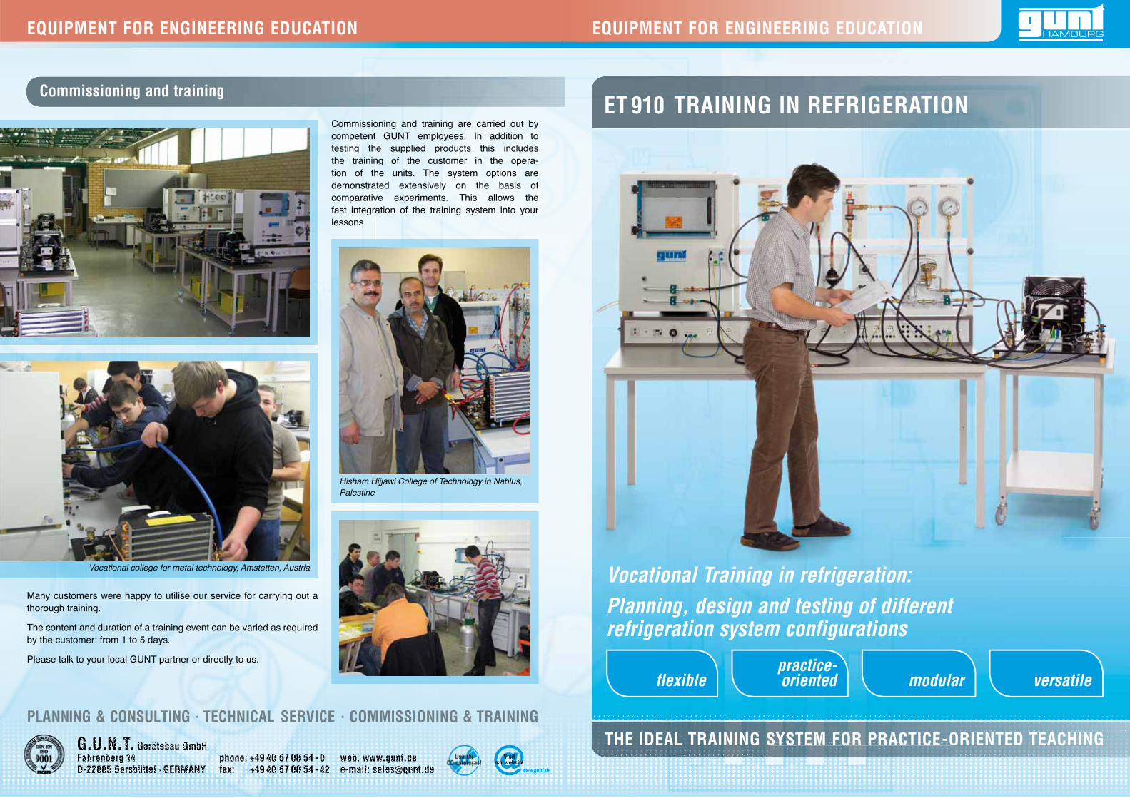
Many customers were happy to utilise our service for carrying out athorough training.
The content and duration of a training event can be varied as requiredby the customer: from 1 to 5 days.
Please talk to your local GUNT partner or directly to us.
Commissioning and training are carried out by competent GUNT employees. In addition to testing the supplied products this includes the training of the customer in the opera-tion of the units. The system options are demonstrated extensively on the basis of comparative experiments. This allows the fast integration of the training system into your lessons.
Commissioning and training
Vocational college for metal technology, Amstetten, Austria
Hisham Hijjawi College of Technology in Nablus, Palestine
versatilemodularpractice-orientedflexible
THE IDEAL TRAINING SYSTEM FOR PRACTICE-ORIENTED TEACHING
Vocational Training in refrigeration:Planning, design and testing of different refrigeration system configurations
EQUIPMENT FOR ENGINEERING EDUCATIONEQUIPMENT FOR ENGINEERING EDUCATION
BASIC KNOWLEDGE BASIC KNOWLEDGE
PSH
PSL
CTCTCTC
°CCC°°TTCCCCCTT
2
1
13
12
11
10
9
8
7
6
3
44
5
TCC
PSHPSH
PSL
Evaporation ACompression B
Condensation C Expansion D
A refrigeration system transports heat from a colder location to a warmer location. In other words, the heat is transported “uphill”.
For this reason it is also called a heat pump, especially if the gain of the system consists in the discharge of heat.
HOW DOES A REFRIGERATION SYSTEM WORK?
Heat absorption during evaporation
gh pressureHig
Low pressureL
Gas
eous
Liqu
id
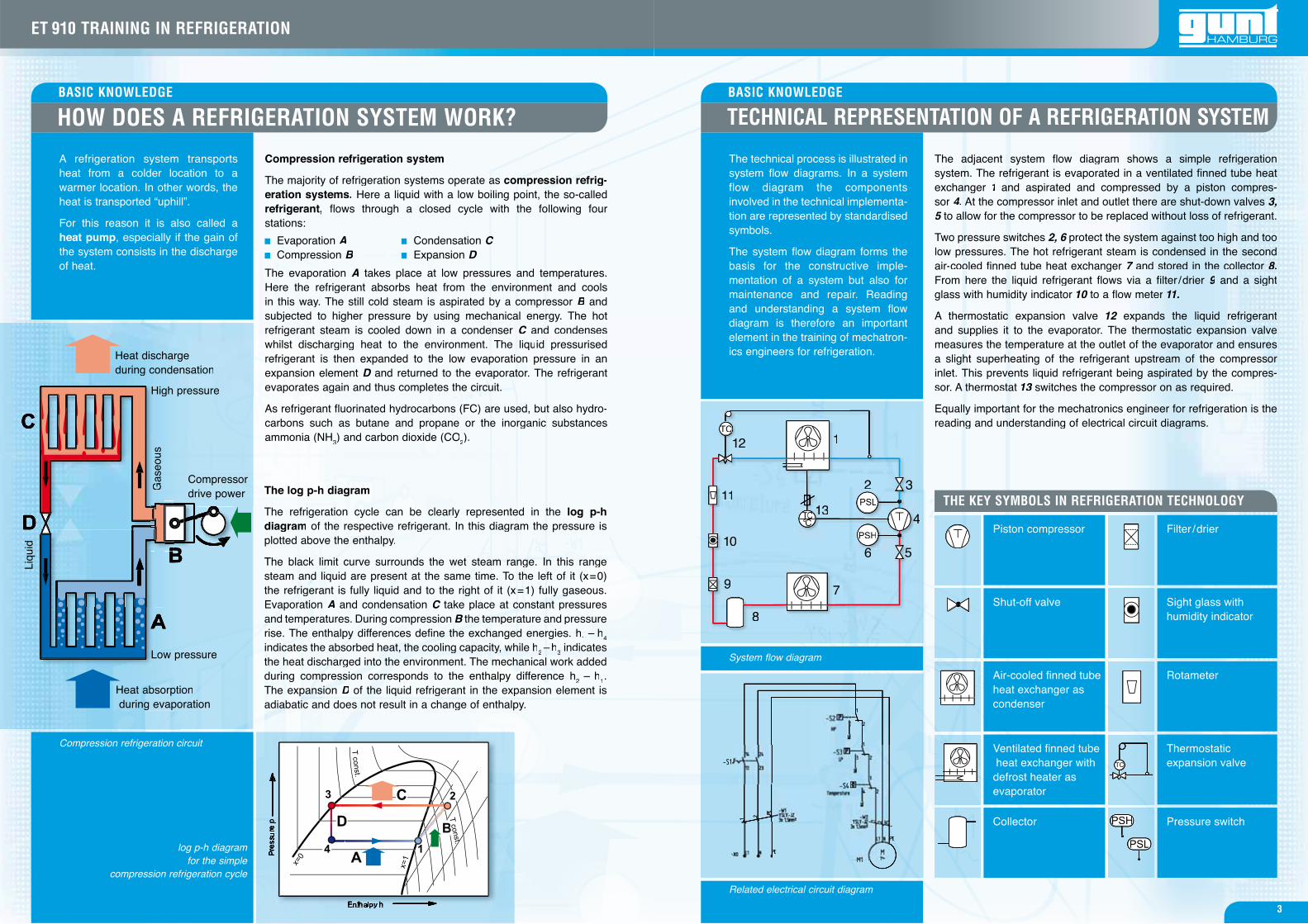
System flow diagram
Related electrical circuit diagram
TECHNICAL REPRESENTATION OF A REFRIGERATION SYSTEM
Shut-off valve Sight glass with humidity indicator
Thermostatic expansion valve
Pressure switch
THE KEY SYMBOLS IN REFRIGERATION TECHNOLOGY
Compression refrigeration system
The majority of refrigeration systems operate as compression refrig-eration systems. Here a liquid with a low boiling point, the so-called refrigerant, flows through a closed cycle with the following fourstations:
The evaporation A takes place at low pressures and temperatures.Here the refrigerant absorbs heat from the environment and cools in this way. The still cold steam is aspirated by a compressor B and Bsubjected to higher pressure by using mechanical energy. The hot refrigerant steam is cooled down in a condenser C and condenses Cwhilst discharging heat to the environment. The liquid pressurised refrigerant is then expanded to the low evaporation pressure in an expansion element D and returned to the evaporator. The refrigerant Devaporates again and thus completes the circuit.
As refrigerant fluorinated hydrocarbons (FC) are used, but also hydro-carbons such as butane and propane or the inorganic substances ammonia (NH3) and carbon dioxide (CO2).
The log p-h diagram
The refrigeration cycle can be clearly represented in the log p-hdiagram of the respective refrigerant. In this diagram the pressure is plotted above the enthalpy.
The black limit curve surrounds the wet steam range. In this range steam and liquid are present at the same time. To the left of it (x=0) the refrigerant is fully liquid and to the right of it (x=1) fully gaseous.Evaporation A and condensation C take place at constant pressures Cand temperatures. During compression B the temperature and pressureBrise. The enthalpy differences define the exchanged energies. h1 – h4
indicates the absorbed heat, the cooling capacity, while h2 – h3 indicates the heat discharged into the environment. The mechanical work addedduring compression corresponds to the enthalpy difference h2 – h1. The expansion D of the liquid refrigerant in the expansion element is Dadiabatic and does not result in a change of enthalpy.
Compression refrigeration circuit
log p-h diagram for the simple
compression refrigeration cycle
Heat discharge during condensation
Compressordrive power
The adjacent system flow diagram shows a simple refrigeration system. The refrigerant is evaporated in a ventilated finned tube heat exchanger 1 and aspirated and compressed by a piston compres-1sor 4. At the compressor inlet and outlet there are shut-down valves 3, 5 to allow for the compressor to be replaced without loss of refrigerant. 5
Two pressure switches 2, 6 protect the system against too high and too 6low pressures. The hot refrigerant steam is condensed in the second air-cooled finned tube heat exchanger 7 and stored in the collector 7 8.From here the liquid refrigerant flows via a filter /drier 9 and a sight 9glass with humidity indicator 10 to a flow meter 0 11.
A thermostatic expansion valve 12 expands the liquid refrigerant2and supplies it to the evaporator. The thermostatic expansion valve measures the temperature at the outlet of the evaporator and ensures a slight superheating of the refrigerant upstream of the compressor inlet. This prevents liquid refrigerant being aspirated by the compres-sor. A thermostat 13 switches the compressor on as required. 3
Equally important for the mechatronics engineer for refrigeration is the reading and understanding of electrical circuit diagrams.
The technical process is illustrated in system flow diagrams. In a system flow diagram the components involved in the technical implementa-tion are represented by standardised symbols.
The system flow diagram forms the basis for the constructive imple-mentation of a system but also for maintenance and repair. Reading and understanding a system flow diagram is therefore an important element in the training of mechatron-ics engineers for refrigeration.
Piston compressor
Air-cooled fi nned tube heat exchanger as condenser
Ventilated fi nned tube heat exchanger with defrost heater as evaporator
Collector
Filter /drier
Rotameter
3
ET 910 TRAINING IN REFRIGERATION
= applications for the ET 910 training system
Principles of electrical engineering
Consumers of single phase alternating current
Protection against electrical hazards
Consumers of three phase alternating current
Electrical drives and fault fi nding
Control of refrigeration systems
Building automation
AIR CONDITIONING TECHNOLOGY
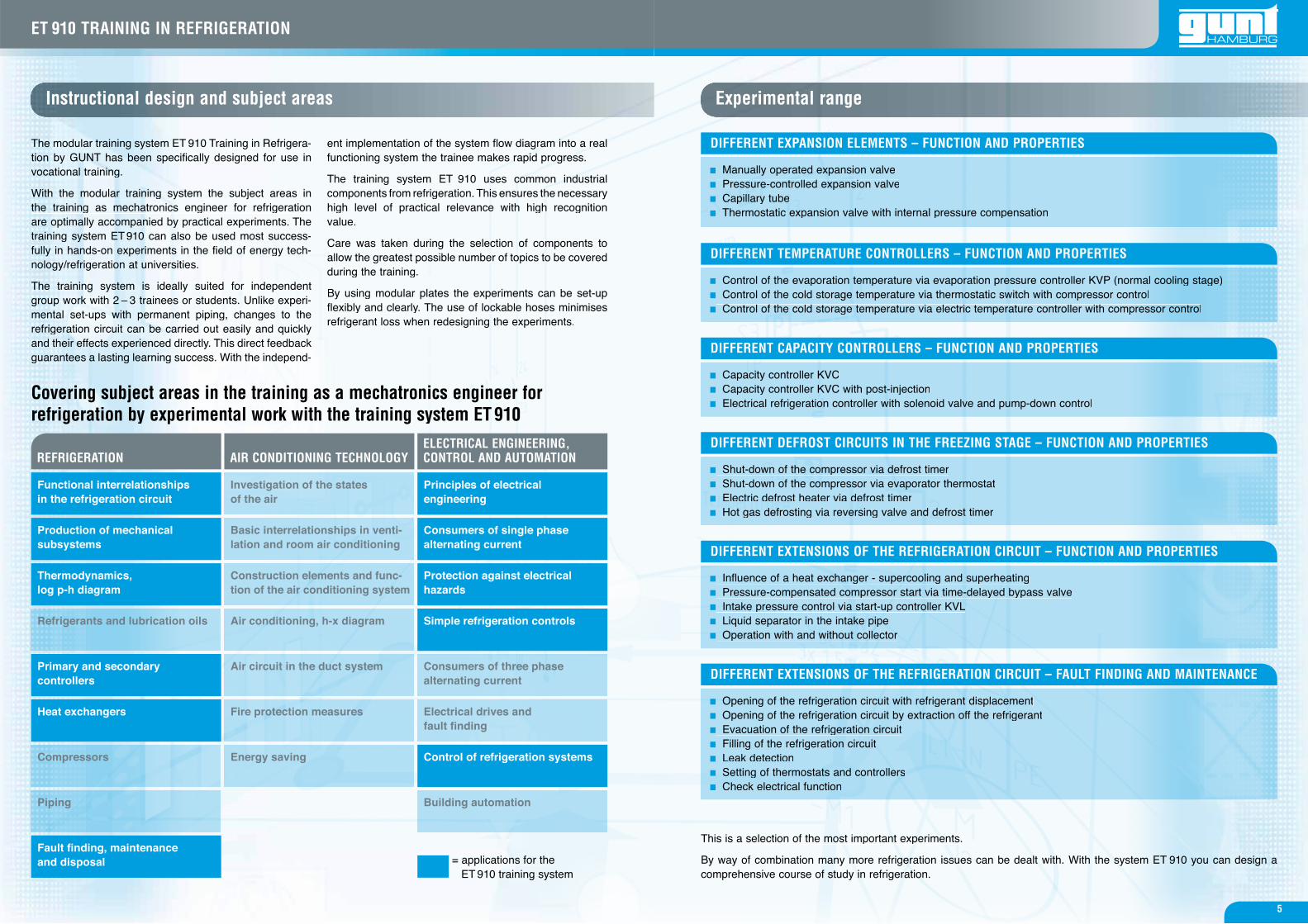
Experimental rangeInstructional design and subject areas
Covering subject areas in the training as a mechatronics engineer forrefrigeration by experimental work with the training system ET 910
The modular training system ET 910 Training in Refrigera-tion by GUNT has been specifically designed for use invocational training.
With the modular training system the subject areas inthe training as mechatronics engineer for refrigerationare optimally accompanied by practical experiments. Thetraining system ET 910 can also be used most success-fully in hands-on experiments in the field of energy tech-nology/refrigeration at universities.
The training system is ideally suited for independent group work with 2 – 3 trainees or students. Unlike experi-mental set-ups with permanent piping, changes to therefrigeration circuit can be carried out easily and quicklyand their effects experienced directly. This direct feedbackguarantees a lasting learning success. With the independ-
ent implementation of the system flow diagram into a real functioning system the trainee makes rapid progress.
The training system ET 910 uses common industrial components from refrigeration. This ensures the necessary high level of practical relevance with high recognition value.
Care was taken during the selection of components to allow the greatest possible number of topics to be covered during the training.
By using modular plates the experiments can be set-up flexibly and clearly. The use of lockable hoses minimises refrigerant loss when redesigning the experiments.
ELECTRICAL ENGINEERING, CONTROL AND AUTOMATIONREFRIGERATION
Functional interrelationships in the refrigeration circuit
Production of mechanical subsystems
Thermodynamics, log p-h diagram
Refrigerants and lubrication oils
Primary and secondary controllers
Heat exchangers
Compressors
Piping
Fault fi nding, maintenance and disposal
Investigation of the statesof the air
Basic interrelationships in venti-lation and room air conditioning
Construction elements and func-tion of the air conditioning system
Air conditioning, h-x diagram
Air circuit in the duct system
Fire protection measures
Energy saving
Simple refrigeration controls
This is a selection of the most important experiments.
By way of combination many more refrigeration issues can be dealt with. With the system ET 910 you can design a comprehensive course of study in refrigeration.
Manually operated expansion valve Pressure-controlled expansion valve Capillary tube Thermostatic expansion valve with internal pressure compensation
Control of the evaporation temperature via evaporation pressure controller KVP (normal cooling stage) Control of the cold storage temperature via thermostatic switch with compressor control Control of the cold storage temperature via electric temperature controller with compressor control
Capacity controller KVC Capacity controller KVC with post-injection Electrical refrigeration controller with solenoid valve and pump-down control
Shut-down of the compressor via defrost timer Shut-down of the compressor via evaporator thermostat Electric defrost heater via defrost timer Hot gas defrosting via reversing valve and defrost timer
Influence of a heat exchanger - supercooling and superheating Pressure-compensated compressor start via time-delayed bypass valve Intake pressure control via start-up controller KVL Liquid separator in the intake pipe Operation with and without collector
Opening of the refrigeration circuit with refrigerant displacement Opening of the refrigeration circuit by extraction off the refrigerant Evacuation of the refrigeration circuit Filling of the refrigeration circuit Leak detection Setting of thermostats and controllers Check electrical function
DIFFERENT EXPANSION ELEMENTS – FUNCTION AND PROPERTIES
DIFFERENT TEMPERATURE CONTROLLERS – FUNCTION AND PROPERTIES
DIFFERENT CAPACITY CONTROLLERS – FUNCTION AND PROPERTIES
DIFFERENT DEFROST CIRCUITS IN THE FREEZING STAGE – FUNCTION AND PROPERTIES
DIFFERENT EXTENSIONS OF THE REFRIGERATION CIRCUIT – FUNCTION AND PROPERTIES
DIFFERENT EXTENSIONS OF THE REFRIGERATION CIRCUIT – FAULT FINDING AND MAINTENANCE
5
ET 910 TRAINING IN REFRIGERATION
The design of our training system
BASIC EQUIPMENT
EXTENSION SET ET 910.11
MAINTENANCE SET ET 910.13
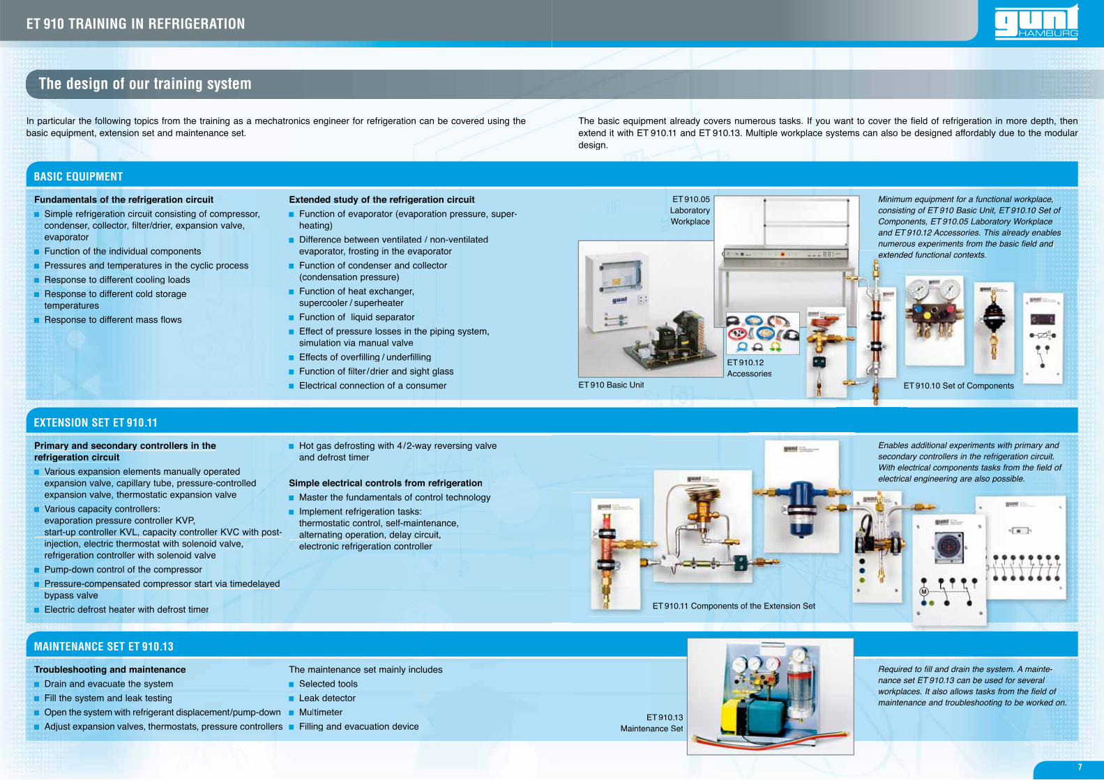
ET 910 Basic Unit
ET 910.05 LaboratoryWorkplace
ET 910.10 Set of ComponentsE
ET 910.13 Maintenance Set
ET 910.12Accessories
Fundamentals of the refrigeration circuit
Simple refrigeration circuit consisting of compressor, condenser, collector, filter/drier, expansion valve, evaporator
Function of the individual components
Pressures and temperatures in the cyclic process
Response to different cooling loads
Response to different cold storage temperatures
Response to different mass flows
Extended study of the refrigeration circuit
Function of evaporator (evaporation pressure, super- heating)
Difference between ventilated / non-ventilated evaporator, frosting in the evaporator
Function of condenser and collector (condensation pressure)
Function of heat exchanger, supercooler / superheater
Function of liquid separator
Effect of pressure losses in the piping system, simulation via manual valve
Effects of overfilling / underfilling
Function of filter /drier and sight glass
Electrical connection of a consumer
The maintenance set mainly includes
Selected tools
Leak detector
Multimeter
Filling and evacuation device
Troubleshooting and maintenance
Drain and evacuate the system
Fill the system and leak testing
Open the system with refrigerant displacement/pump-down
Adjust expansion valves, thermostats, pressure controllers
In particular the following topics from the training as a mechatronics engineer for refrigeration can be covered using the basic equipment, extension set and maintenance set.
Primary and secondary controllers in the refrigeration circuit
Various expansion elements manually operated expansion valve, capillary tube, pressure-controlled expansion valve, thermostatic expansion valve
Various capacity controllers: evaporation pressure controller KVP, start-up controller KVL, capacity controller KVC with post- injection, electric thermostat with solenoid valve, refrigeration controller with solenoid valve
Pump-down control of the compressor
Pressure-compensated compressor start via timedelayed bypass valve
Electric defrost heater with defrost timer
Hot gas defrosting with 4/2-way reversing valve and defrost timer
Simple electrical controls from refrigeration
Master the fundamentals of control technology
Implement refrigeration tasks: thermostatic control, self-maintenance, alternating operation, delay circuit, electronic refrigeration controller
Minimum equipment for a functional workplace, consisting of ET 910 Basic Unit, ET 910.10 Set of Components, ET 910.05 Laboratory Workplace and ET 910.12 Accessories. This already enables numerous experiments from the basic field and
ed functional contexts.extendeextend.
Enables additional experiments with primary and secondary controllers in the refrigeration circuit.With electrical components tasks from the field of electrical engineering are also possible.electrical enginee
Required to fill and drain the system. A mainte-nance set ET 910.13 can be used for several workplaces. It also allows tasks from the field of maintenance and troubleshooting to be worked on.
The basic equipment already covers numerous tasks. If you want to cover the field of refrigeration in more depth, then extend it with ET 910.11 and ET 910.13. Multiple workplace systems can also be designed affordably due to the modular design.
910.11 Components of the Extension Set910 11 Components of the ExtenET ET
7
ET 910 TRAINING IN REFRIGERATION
Component 10/02:nent 10/02:t 10/02Flow meter
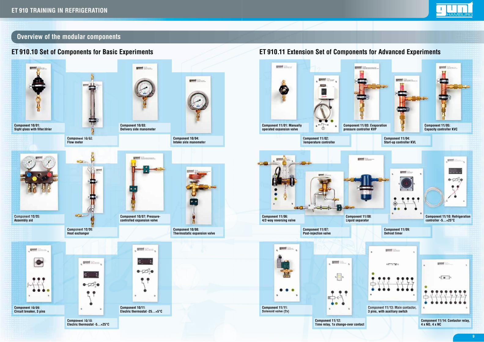
Component 11/12:Time relay, 1x change-over contact
CComponent 11/02:Temperature controllerTemperature controller
Component 11/07:Post-injection valve
Overview of the modular components
ET 910.10 Set of Components for Basic Experiments ET 910.11 Extension Set of Components for Advanced Experiments
Component 10/01:Sight glass with fi lter/drier
CComponent 11/11:Solenoid valve (2x)Solenoid valve (2x)
ponent 11/03: Evaporamp tion Comure controller KVPsspre
Component 10/05:Component 10/05:Assembly aid
Component 10/09:t 10/09Circuit breaker, 3 pins
Commponent 10/06:ponent 10/06:Heat exchangerat exchanger
Component 10/10:t 10/10Electric thermostat -5...+25°C
Component 10/04:Intake side manometer
Component 11/04:Start-up controller KVL
Component 11/09:Defrost timer
Component 10/08: pThermostatic expansion valve
Component 11/13: Main contactor, Component 11/13: Main contactor3 pins, with auxiliary switch
Component 10/07: Pressure-Component 10/07: Pressure-controlled expansion valve
Component 10/11:t 10/11Electric thermostat -25...+5°C
nent 11/08:npmponComseparatoruid sLiqu
Component 10/03:Delivery side manometer
Coomponent 11/01: Manuallyy operated expansion valveperated expansion valve
Component 11/06:4/2-way reversing vallve
Component 11/14: Contactor relay, 4 x NO, 4 x NC
ponent 11/05:mCoacity controller KVCpaCa
Component 11/10: Refrigeration CCComponent 11/10: RefrigerationCCcontroller -5...+25°Ccc
9
ET 910 TRAINING IN REFRIGERATION
PSH
PSL
TCTCTC
1
2
4
3
5
6
7
89
4
7 6 10
95 8
1, 2, 37
Accessory Set ET 910.12
System flow diagram
Exemplary experimental set-ups
The accessory set ET 910.12 is required for the hydraulicand electrical connection of the modules to each other andto the basic unit. It includes refrigerant hoses of different lengths and diameters (some with shut-off valves), refrig-erant filtes/driers as replacement, T pieces, couplings and
laboratory cables. Two capillary tubes of different lengths, two distributors and a sufficient length of insulating hose are also included.
Below some interesting experimental set-ups madepossible by the training system are introduced by way ofexample:
Simple refrigeration circuit with compressor, condenser,thermostatic expansion valve and evaporator
Refrigeration circuit with capacity control and post-injection
Refrigeration circuit with hot gas defrosting of the evaporator
When working with the training system the trainee firstlearns to read and understand refrigeration system flow diagrams and simple electric circuit diagrams.
When combining the necessary experimental components he is familiarised with the real refrigeration components corresponding to the flow diagrams.
During commissioning practical tasks, such as evacuat-ing, filling and leak tests, are carried out. The relevant regulations and guidelines can be trained in the process.In the final experiment stage the trainee can literally grasp the function of the system. The function is optimised by the adjustment of controllers and expansion elements.The effects of external influences, e.g the evaporator temperature, on the behaviour and capacity of the refrig-eration system can be demonstrated.
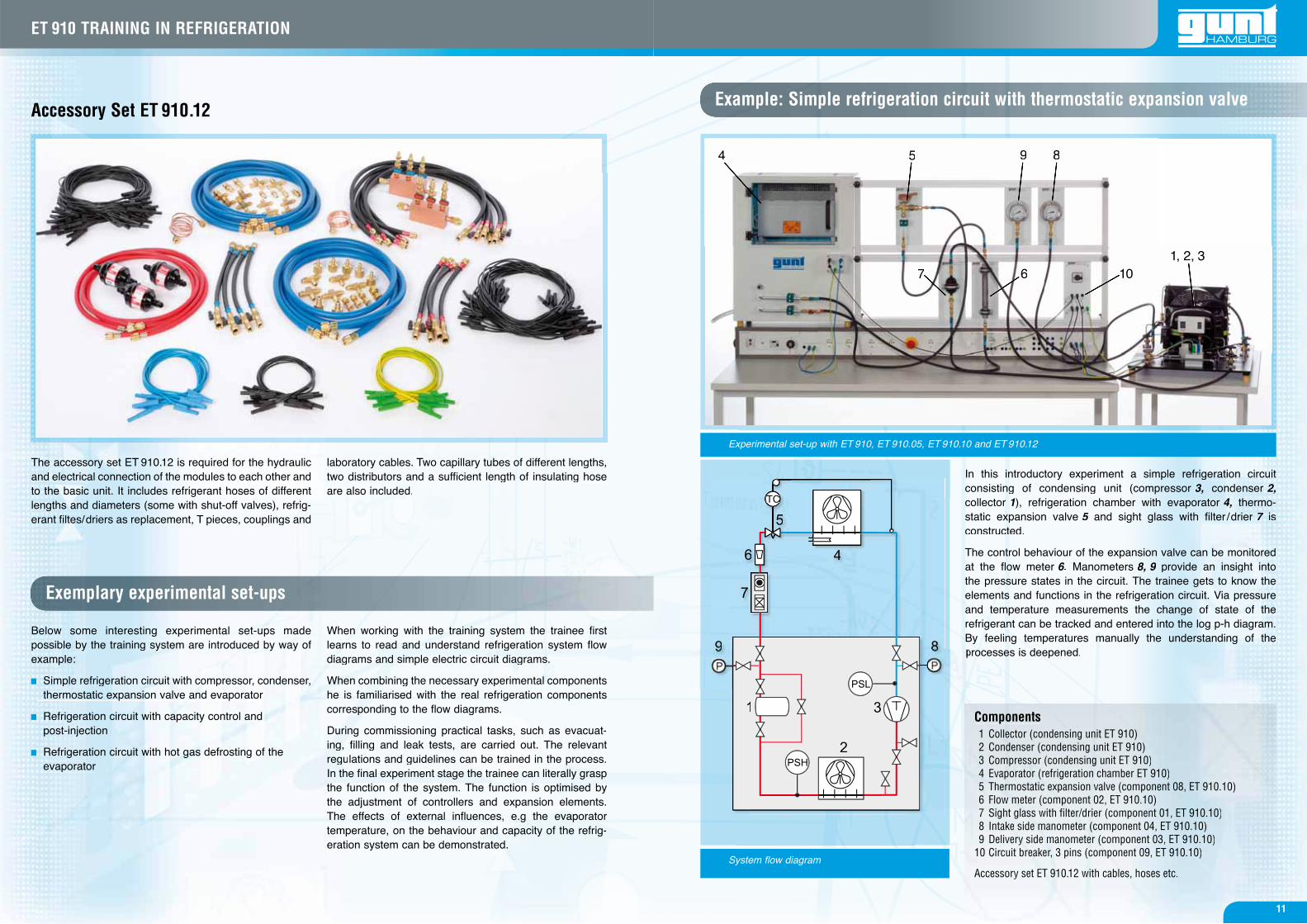
Example: Simple refrigeration circuit with thermostatic expansion valve
In this introductory experiment a simple refrigeration circuit consisting of condensing unit (compressor 3, condenser 2,collector 1), refrigeration chamber with evaporator 4, thermo-static expansion valve 5 and sight glass with filter /drier5 7 is 7constructed.
The control behaviour of the expansion valve can be monitored at the flow meter 6.66 Manometers 8, 9 provide an insight into 9the pressure states in the circuit. The trainee gets to know the elements and functions in the refrigeration circuit. Via pressure and temperature measurements the change of state of the refrigerant can be tracked and entered into the log p-h diagram. By feeling temperatures manually the understanding of the processes is deepened.
Experimental set-up with ET 910, ET 910.05, ET 910.10 and ET 910.12
Components1 Collector (condensing unit ET 910)2 Condenser (condensing unit ET 910)3 Compressor (condensing unit ET 910)4 Evaporator (refrigeration chamber ET 910)5 Thermostatic expansion valve (component 08, ET 910.10)6 Flow meter (component 02, ET 910.10)7 Sight glass with fi lter/drier (component 01, ET 910.10)8 Intake side manometer (component 04, ET 910.10)9 Delivery side manometer (component 03, ET 910.10)
10 Circuit breaker, 3 pins (component 09, ET 910.10)
Accessory set ET 910.12 with cables, hoses etc.
11
ET 910 TRAINING IN REFRIGERATION
PSH
PSL
CTCTCTC
PTCCCTT
1
2
3
4 56
7
89
10
11P P
PSH
PSL
TCCTC
1
2
3
45
6
7
8
9
1011P P
6 57 6
89
10 8
13
12
4
4
11 109 5 712 11
1, 2, 3 1, 2, 38 1
8
System flow diagram System flow diagram
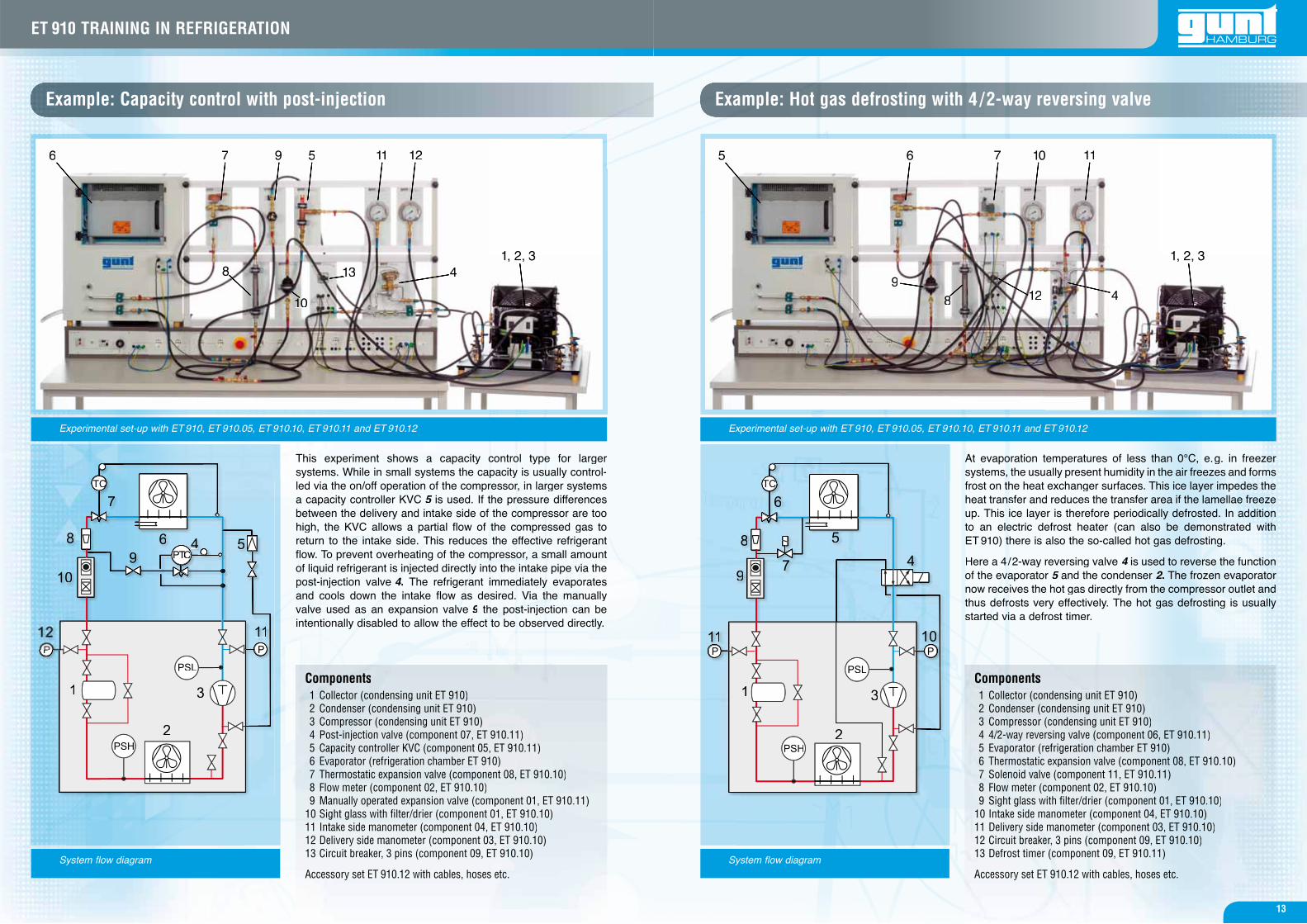
Example: Capacity control with post-injection
This experiment shows a capacity control type for larger systems. While in small systems the capacity is usually control-led via the on/off operation of the compressor, in larger systems a capacity controller KVC 5 is used. If the pressure differences 5between the delivery and intake side of the compressor are too high, the KVC allows a partial flow of the compressed gas to return to the intake side. This reduces the effective refrigerantflow. To prevent overheating of the compressor, a small amount of liquid refrigerant is injected directly into the intake pipe via the post-injection valve 4. The refrigerant immediately evaporates and cools down the intake flow as desired. Via the manually valve used as an expansion valve 9 the post-injection can be 9intentionally disabled to allow the effect to be observed directly.
Experimental set-up with ET 910, ET 910.05, ET 910.10, ET 910.11 and ET 910.12
Components1 Collector (condensing unit ET 910)2 Condenser (condensing unit ET 910)3 Compressor (condensing unit ET 910)4 Post-injection valve (component 07, ET 910.11)5 Capacity controller KVC (component 05, ET 910.11)6 Evaporator (refrigeration chamber ET 910)7 Thermostatic expansion valve (component 08, ET 910.10)8 Flow meter (component 02, ET 910.10)9 Manually operated expansion valve (component 01, ET 910.11)
10 Sight glass with fi lter/drier (component 01, ET 910.10)11 Intake side manometer (component 04, ET 910.10)12 Delivery side manometer (component 03, ET 910.10)13 Circuit breaker, 3 pins (component 09, ET 910.10)
Accessory set ET 910.12 with cables, hoses etc.
Example: Hot gas defrosting with 4 /2-way reversing valve
At evaporation temperatures of less than 0°C, e.g. in freezer systems, the usually present humidity in the air freezes and forms frost on the heat exchanger surfaces. This ice layer impedes the heat transfer and reduces the transfer area if the lamellae freeze up. This ice layer is therefore periodically defrosted. In addition to an electric defrost heater (can also be demonstrated with ET 910) there is also the so-called hot gas defrosting.
Here a 4/2-way reversing valve 4 is used to reverse the function 4of the evaporator 5 and the condenser 2.22 The frozen evaporator now receives the hot gas directly from the compressor outlet and thus defrosts very effectively. The hot gas defrosting is usually started via a defrost timer.
Experimental set-up with ET 910, ET 910.05, ET 910.10, ET 910.11 and ET 910.12
Components1 Collector (condensing unit ET 910)2 Condenser (condensing unit ET 910)3 Compressor (condensing unit ET 910)4 4/2-way reversing valve (component 06, ET 910.11)5 Evaporator (refrigeration chamber ET 910)6 Thermostatic expansion valve (component 08, ET 910.10)7 Solenoid valve (component 11, ET 910.11)8 Flow meter (component 02, ET 910.10)9 Sight glass with fi lter/drier (component 01, ET 910.10)
10 Intake side manometer (component 04, ET 910.10)11 Delivery side manometer (component 03, ET 910.10)12 Circuit breaker, 3 pins (component 09, ET 910.10)13 Defrost timer (component 09, ET 910.11)
Accessory set ET 910.12 with cables, hoses etc.
13
ET 910 TRAINING IN REFRIGERATION
Arbeitsblätter
Technische DatenTechnische Daten 2cm 70 80 90 100 110
18
6 Anhang
ET 910 ÜBUNGSSYSTEM KÄLTETECHNIK
05/2009
2.1.1 Kältemittelverdichter
Der hermetische Kältemittelverdichter besitzt
ein geschweißtes Blechgehäuse. Der Antriebsmo-
tor und Kältemittelverdichter sind in dieser Kapsel
untergebracht. Somit ist der Kältemittelverdichter
direkt mit dem Antriebsmotor verbunden und
braucht auch keine Gleitringdichtung wie der
offene Kältemittelverdichter. Der Läufer ist auf der
Kurbelschleife montiert.
Es gibt Kapseln, bei welchen der elektrische An-
triebsmotor unten und bei anderen oben angeord-
net ist. Der Motorverdichter ist in dem Kapselge-
häuse mit Federn aufgehängt, wodurch verhindert
wird, dass Pulsationsgeräusche auf die Kapsel ge-
leitet werden können. Die kapselinternen Druck-
und Saugleitungen sind flexibel ausgeführt, damit
beim Anlauf die Rohre nicht abbrechen.
Die elektrischen Anschlüsse stellen die notwen-
digen Verbindungen zum Betrieb des Kältemittel-
verdichters her. Der elektrische Anschluss erfolgt
über abgedichtete Stifte, damit kein Kältemittel
austritt.
Die Schmierung erfolgt mit einer Zentrifugalpum-
pe. Restliches Öl tritt am oberen Lager aus und
läuft an der Kapselwand nach unten in den Öl-
sumpf.
Viele Kapseln sind saugdampfgekühlt bis auf
einige, die mit Öl- oder Heißdampfkühlung ausge-
rüstet sind. Eine Kapsel steht normalerweise unter
dem in der Anlage vorhandenen Saugdruck.
4
2 Gerätebeschreibung
ET 910 ÜBUNGSSYSTEM KÄLTETECHNIK05/2009
A Läufer
B Ständer
C Zylinder
D Kolben
E Kolbenstange
F Kurbelschleife
G Kapselgehäuse
H Elektrische Anschlüsse
Abb. 2.2 Schnittbild Kältemittelver-
dichter
Abb. 2.1 aufgeschnittener
Kältemittelverdichter
5.5.1 Experiment 9 : Leistungsregler KVC
Für Leistungsregler gibt es keinen standardisier-
ten Einbaufall. In diesem Experiment wird ein ein-
facher Einbaufall dargestellt, bei dem der Lei-
stungsregler den Saugdruck des Verdichters kon-
stant hält.
Eine Leitung, im folgenden Bypass genannt ver-
bindet die Druckseite mit der Saugseite des Ver-
dichters. Der überhitzte Heißdampf wird von der
Druckseite des Verdichters im Bypass, über den
Leistungsregler, auf die Saugseite des Verdich-
ters zurück geleitet. Diese Schaltungsart wird als
Heißdampfbypassregelung bezeichnet. In der
Praxis verdampft Kältemittel unter Aufnahme von
Umgebungswärme im Verdampfer und kühlt Bei-
spielsweise einen Raum. Mit zunehmender Ab-
kühlung sinkt der Druck im Verdampfer immer wei-
ter ab.
Mit sinkendem Verdampfungsdruck im Verdamp-
fer nimmt der Wärmestrom (Kältemittelmassen-
strom) ab. Durch die steigende Druckdifferrenz
nimmt die vom Verdichter zu leistende mechani-
sche Arbeit zu. Mit dem Leistungsregler im Bypass
wird ein Teil des Kältemittelmassenstromes von
der Druckseite des Verdichters der Saugseite zu-
rückgeführt. Der Kältemittelmassenstrom im Ver-
flüssiger und anschließend im Verdampfer wird
verringert und damit die Verdampferleistung redu-
ziert. Das im Kreislauf zwischen Druck- und Saug-
seite des Verdichters strömende Kältemittel er-
wärmt sich und die Überhitzungstemperatur am
Verdichtereingang steigt. Es ist darauf zu achten,
das die Temperatur des Öls, zur Schmierung des
Verdichters, sich nicht unzulässig erhöht oder der
Verdichter sich überhitzt. Der Verflüssigungsdruck
sinkt , da der Kältemit te lmassenstrom
abgenommen hat.
5 Experimente
15
ET 910 ÜBUNGSSYSTEM KÄLTETECHNIK05/2009
Alle
Rec
hte
vorb
ehal
ten
G.U
.N.T
.Ger
äteb
auG
mbH
,Bar
sbüt
tel0
5/20
09
Stückliste Experiment 9:
Pos Kältekomponente:
1-16 auf dem Verflüssigersatz
17 Filter und Schauglas
18 Durchflussmesser
19Thermostatisches
Drosselventil
20 Heizung (ausgeschaltet)
21 Verdampfer
22 Leistungsregler KVC
Elektrokomponente:
Ausschalter 3-polig
Laborkabel
Stromversorgung
Pressostate am Verdichter
Hilfsmittel:
Monteurhilfe
Kältemittel
Vakuumstation
Druckmanometer
Saugmanometer
18
ET 910
6.1 Bedienung des Thermostats
Bitte unbedingt ausfüllen!
6 Anhang
19
ET 910 ÜBUNGSSYSTEM KÄLTETECHNIK05/2009
Alle
Rec
hte
vorb
ehal
ten
G.U
.N.T
.Ger
äteb
auG
mbH
,Bar
sbüt
tel0
5/20
09
r besitzt
triebsmo-
er Kapsel
verdichter
nden und
g wie der
er ist auf der
ektrische An-
ben angeord-
em Kapselge-
rch verhindert
die Kapsel ge-
nternen Druck-
sgeführt, damit
echen.
ellen die notwen-
des Kältemittel-
Anschluss erfolgt
kein Kältemittel
er Zentrifugalpum-
ren Lager aus und
h unten in den Öl-
mpfgekühlt bis auf
ampfkühlung ausge-
normalerweise unter
enen Saugdruck.
2 Gerätebeschreibung
2.1.2 Druckgeregeltes Drosselventil
Der Einbau eines druckgeregelten Drosselven-
tils (9) erfolgt auf der Hochdruckseite (flüssiges
Kältemittel) vor dem Verdampfer.Der Verdampfungsdruck im Verdampfer und da-
mit die Verdampfungstemperatur sind über das
druckgeregelte Drosselventil einstellbar und wer-
den konstant gehalten. Das Drosselventil öffnet,
wenn der eingestellte Druck nach dem Drossel-
ventil unterschritten wird und schließt, wenn der
Wert überschritten wird. Das Kältemittel tritt bei (8)
ein und bei (10) aus. Das druckgeregelte Drossel-
ventil wird in einem Kältemittelkreislauf ohne
Sammler angewendet und wird wie folgt einge-
stellt:Eine Umdrehung der Regulierschraube (11) im
Uhrzeigersinn erhöht den Verdampfungsdruck um
ca. 0,8 bar. Eine Umdrehung entgegengesetzt
dem Uhrzeigersinn verringert den Verdampfungs-
druck um ca. 0,8 bar.Das Drosselventil funktioniert wie folgt:Mit der Regulierschraube (5) wird die Regulierfe-
der (4) vorgespannt. Die Regulierfeder wirkt mit ih-
rer Kraft in Öffnungsrichtung und damit entgegen-
gesetzt den Kräften von Gegenfeder (6) und dem
Druck unter der Membran (1). Der Übertragungs-
stift (2) bringt die wirkenden Kräfte zusammen.
Nach der Düse (7) und der Nadel (3) verdampft
das flüssige Kältemittel teilweise und erhöht somit
den Druck im Verdampfer. Bei laufendem Verdich-
ter wird das gasförmige Kältemittel aus dem Ver-
dampfer gesogen und der Verdampfungsdruck
bleibt bei nachströmendem Kältemittel konstant.
Ist der Verdichter aus, steigt der Verdampfungs-
druck im Verdampfer an und die Nadel schließt die2 Gerätebeschreibung
5
ET 910 ÜBUNGSSYSTEM KÄLTETECHNIK
05/2009
Alle
Rec
hte
vorb
ehal
ten
G.U
.N.T
. Ger
äteb
auG
mbH
, Bar
sbüt
tel 0
5/20
09
Abb. 2.2 Symbol Drosselventil
Abb. 2.3 Schnitt Drosselventil
Abb. 2.4 Ansicht Drosselventil
11
8
9
10
dardisier-
rd ein ein-
m der Lei-
chters kon-
enannt ver-
eite des Ver-
wird von der
ss, über den
des Verdich-
gsart wird als
chnet. In der
Aufnahme von
r und kühlt Bei-
nehmender Ab-
mpfer immer wei-
uck im Verdamp-
ältemittelmassen-
e Druckdifferrenz
eistende mechani-
gsregler im Bypass
massenstromes von
s der Saugseite zu-
assenstrom im Ver-
im Verdampfer wird
ampferleistung redu-
hen Druck- und Saug-
mende Kältemittel er-
itzungstemperatur am
Es ist darauf zu achten,
ls, zur Schmierung des
zulässig erhöht oder der
Der Verflüssigungsdruck
emit te lmassenstrom
15
Das Öffnen und Schließen des Leistungsreglers
ist im Experiment aufgrund des Strömungsgeräu-
sches hörbar. Das Hochdruckmanometer zeigt an,
bei welchem Druck der Leistungsregler reagiert.
14
5 Experimente
ET 910 ÜBUNGSSYSTEM KÄLTETECHNIK
05/2009
PC
PI
7/16" red
TC
17
18
19
20
21
3/8" blue
7/16" red
7/16" red
7/16" red
3/8" blue
1
2
3
5
6
7
89
10
11
12
P-
P+13
14
15
16
4
EL
22
Abb. 5.1 RI-Fließbild Experiment 9: Leistungsregler KVC
Insights from the experiments The instructional material
Detailed description of the components
Original manufacturer documentationO i i l f d
With the purchase of the
training system ET 910
you receive a first class
documentation and
teaching aid.
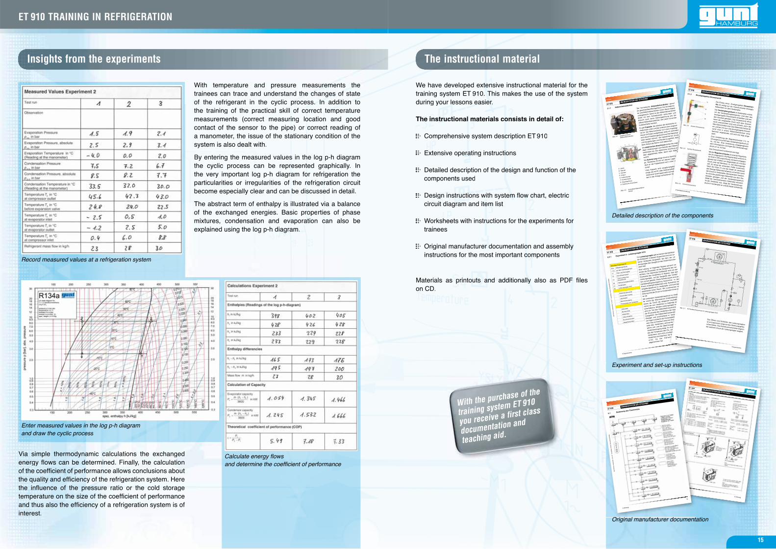
Record measured values at a refrigeration system
With temperature and pressure measurements thetrainees can trace and understand the changes of stateof the refrigerant in the cyclic process. In addition tothe training of the practical skill of correct temperaturemeasurements (correct measuring location and goodcontact of the sensor to the pipe) or correct reading ofa manometer, the issue of the stationary condition of thesystem is also dealt with.
By entering the measured values in the log p-h diagramthe cyclic process can be represented graphically. Inthe very important log p-h diagram for refrigeration theparticularities or irregularities of the refrigeration circuitbecome especially clear and can be discussed in detail.
The abstract term of enthalpy is illustrated via a balanceof the exchanged energies. Basic properties of phasemixtures, condensation and evaporation can also beexplained using the log p-h diagram.
Via simple thermodynamic calculations the exchangedenergy fl ows can be determined. Finally, the calculationof the coeffi cient of performance allows conclusions aboutthe quality and effi ciency of the refrigeration system. Herethe infl uence of the pressure ratio or the cold storagetemperature on the size of the coeffi cient of performanceand thus also the effi ciency of a refrigeration system is ofinterest.
Calculate energy fl ows and determine the coeffi cient of performance
Enter measured values in the log p-h diagram and draw the cyclic process
Experiment and set-up instructions
We have developed extensive instructional material for the training system ET 910. This makes the use of the system during your lessons easier.
The instructional materials consists in detail of:
Comprehensive system description ET 910
Extensive operating instructions
Detailed description of the design and function of the components used
Design instructions with system fl ow chart, electric circuit diagram and item list
Worksheets with instructions for the experiments for trainees
Original manufacturer documentation and assembly instructions for the most important components
Materials as printouts and additionally also as PDF fi les on CD.
15
ET 910 TRAINING IN REFRIGERATION