Embed Size (px)
Citation preview

Commissioning of the ATLAS Energy Upgrade Cryomodule
Peter N. Ostroumov,
Joel Fuerst, Scott Gerbick, Mark Kedzie, Mike Kelly, Steve MacDonald, Richard Pardo, Sergey Sharamentov, Ken Shepard, Gary Zinkann
11th International Conference on
HEAVY ION ACCELERATOR TECHNOLOGY
June 8-12, 2009

2P.N. Ostroumov, et al. 11th Inter. Conf. on Heavy-Ion Accelerator Technology June 8-12, 2009
Content
Goal of the project– New design of a low-beta cryomodule– ATLAS energy upgrade
Cavity parameters– Steering compensation– EM properties are well optimized
Cryomodule assembly– Surface processing– Clean-room assembly
Off-line commissioning– Pumping out, leak check, cool-down– Cold tests
RF systemInstallation– New solenoid, cold trap– Alignment

3P.N. Ostroumov, et al. 11th Inter. Conf. on Heavy-Ion Accelerator Technology June 8-12, 2009
The goal
QWRs are extended vertically: box cryomodulesOriginally developed for large scale production, FRIBSeparation of the cavity vacuum space from the insulating vacuum– Similar to βG=1 cavities in electron linacs: JLAB, ILC
High performance– Optimized design of the cavities, EM, structural, Cancel the beam steering
effect due to the RF field in the QWR– Surface processing, clean-room assembly, low-particulate pumping and
venting system
Top loaded cryomodule: minimize clean-room proceduresMinimize distance between the cryomodules and provide space for beam diagnostics boxDemonstrate average 27.5 MV/m peak surface field: design goal for ANL/FRIBUpgrade ATLAS beam energies– CARIBU beams, q/A ≈ 1/7, W = 10 MeV/u

4P.N. Ostroumov, et al. 11th Inter. Conf. on Heavy-Ion Accelerator Technology June 8-12, 2009
CARIBU
Tandem New cryomodule
ATLAS Layout, May 28th 2009
PII Booster
ATLAS

5P.N. Ostroumov, et al. 11th Inter. Conf. on Heavy-Ion Accelerator Technology June 8-12, 2009
Compensation of the beam-steering effect
0 5 10 15 20 25 30 35 40-12
-10
-8
-6
-4
-2
0
2
4
6
8
10
12
Hx
Ey
Ez
Distance (cm)
Ey, E
z (M
V/m
)
-8
-6
-4
-2
0
2
4
6
8
Hx (kA
/m)
(1) By cavity displacement in vertical plane: useful for heavy ions(2) By reshaping of the drift tubes: universal for all regimes
Beam tests will be available in 1-2 weeks from now

6P.N. Ostroumov, et al. 11th Inter. Conf. on Heavy-Ion Accelerator Technology June 8-12, 2009
58Ni14+ beam parameters at the entrance of the last solenoid in the F-cryostat as measured recently
0.470.2Normalized 90%
4.82.1Un-normalized 90%
0.110.065Normalized 1 rms
YXEmittance (π mm mrad)
XX’ YY’
cm
rad
2.040.53Beta
2.790.06Alpha
YXTwiss parameters

7P.N. Ostroumov, et al. 11th Inter. Conf. on Heavy-Ion Accelerator Technology June 8-12, 2009
Uranium beam dynamics in the upgraded cryomodule
Win=6 MeV/u, B_sol_after “F” = 5.5 T
Aperture
New cryomodule
New solenoid

8P.N. Ostroumov, et al. 11th Inter. Conf. on Heavy-Ion Accelerator Technology June 8-12, 2009
ATLAS beam energies with the upgrade cryomodule
Average accelerating gradient, 9.4 MV/m, demonstrated with the VCX, routine operation is recommended at 8.45 MV/m, provides 14.8 MV,this is 27.0 MV/m peak surface field
Ion Q1 W (MeV/u) Q1/Q2 W (MeV/u) 12C 4 19.3 4/6 23.9 16O 6 20.9 6/8 24.3 28Si 9 18.8 7/14 23.1 50Ti 13 16.2 12/21 20.8 64Ni 14 14.3 14/25 19.7 84Kr 15 12.2 15/31 18.5 92Mo 21 14.7 21/34 19.2 127Xe 25 13.2 25/40 17.1 178Hf 31 12.0 31/50 15.7 208Pb 36 11.9 36/55 15.1 238U 34 10.0

9P.N. Ostroumov, et al. 11th Inter. Conf. on Heavy-Ion Accelerator Technology June 8-12, 2009
Top-loaded cryostat
Module-to-module spacing
21 cm
a) Space-efficientb) Consistent with the requirementsfor high performance SRF surfaces.
The end walls of the vacuum vessel are chamfered in the middle

10P.N. Ostroumov, et al. 11th Inter. Conf. on Heavy-Ion Accelerator Technology June 8-12, 2009
Main design parameters of the SC cavities
Cavity Parameters 1 MV/m 15 MV/m
Frequency 109.125 MHzbeta 0.14U0 0.17 37.40 Jlength 25.00 cmβλ/2 39.05 cmEPEAK 3.20 48.00 MV/mBPEAK 58.30 874.50 GG 39.90 OhmRsh/Q 547.49 Ohm
RF coupler
VCX
mechanicaldamper
RF coupler
VCX
mechanicaldamper
11P.N. Ostroumov, et al. 11th Inter. Conf. on Heavy-Ion Accelerator Technology June 8-12, 2009
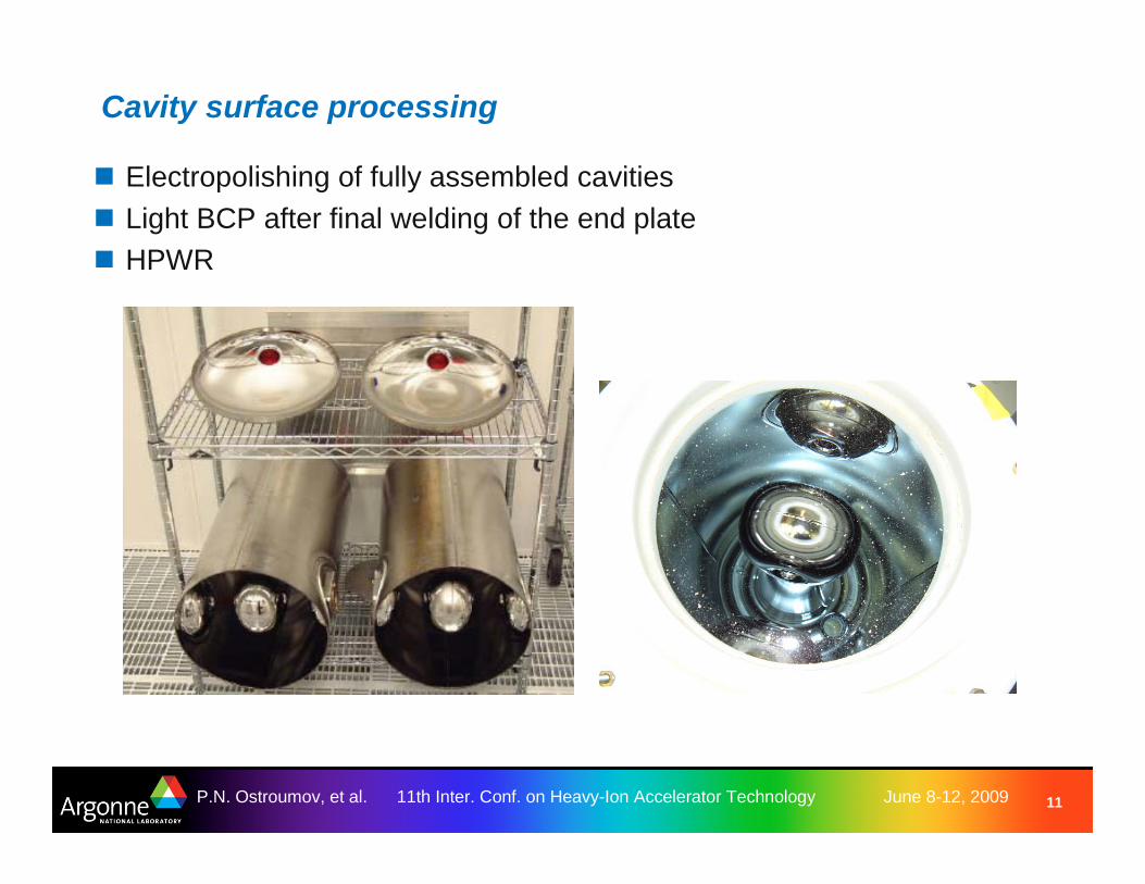
Cavity surface processing
Electropolishing of fully assembled cavitiesLight BCP after final welding of the end plateHPWR

12P.N. Ostroumov, et al. 11th Inter. Conf. on Heavy-Ion Accelerator Technology June 8-12, 2009
Cavity and its sub-systems
Designed for negligible beam loading: requires ~60 W RF amplifier to operate, critically coupled to ~2×10⁸ which is an intrinsic Q0 with VCXRequires fast tuner which is VCX

13P.N. Ostroumov, et al. 11th Inter. Conf. on Heavy-Ion Accelerator Technology June 8-12, 2009
The cavity string assembly in the clean area (between class 10 and 100) is complete, including complete, sealed cavity vacuum system

14P.N. Ostroumov, et al. 11th Inter. Conf. on Heavy-Ion Accelerator Technology June 8-12, 2009
Cavity string suspended from the lid, with all cryogenic plumbing assembled and leak-checked, ready to drop into the box vacuum vessel
15P.N. Ostroumov, et al. 11th Inter. Conf. on Heavy-Ion Accelerator Technology June 8-12, 2009
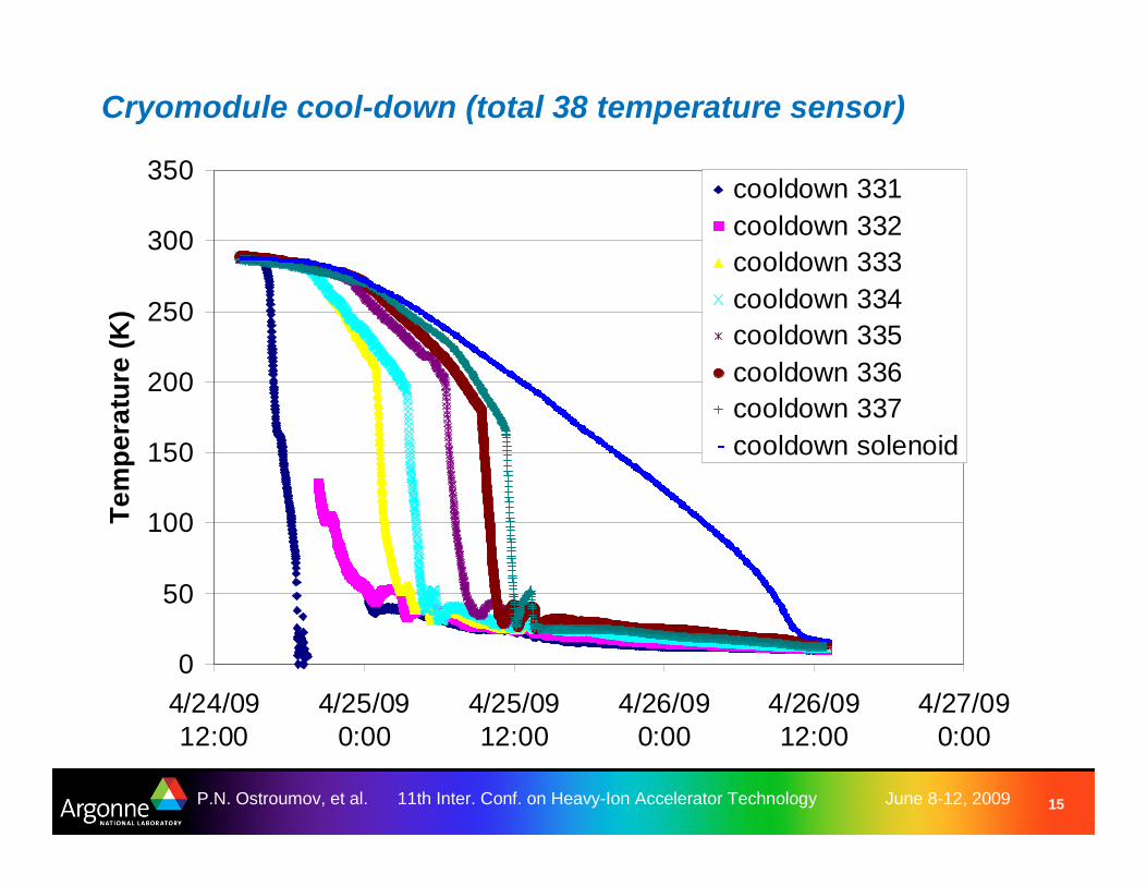
Cryomodule cool-down (total 38 temperature sensor)
0
50
100
150
200
250
300
350
4/24/0912:00
4/25/090:00
4/25/0912:00
4/26/090:00
4/26/0912:00
4/27/090:00
Tem
per
atu
re (
K)
cooldown 331cooldown 332cooldown 333cooldown 334cooldown 335cooldown 336cooldown 337cooldown solenoid

16P.N. Ostroumov, et al. 11th Inter. Conf. on Heavy-Ion Accelerator Technology June 8-12, 2009
Accelerating fields
Maximum in 2 cavities = 15 MV/m – VMAX=3.75 MV, EPEAK= 48 MV/m BPEAK= 875 Gauss
Limited by VCX = 9.4 MV/m, averaged over 7 cavities– Large stored energy, tuning window is fixed, reactive power ~27 KVA
Recommended for routine operation = 8.4 MV/m
0
2
4
6
8
10
12
14
16
EA
CC (
MV
/m)
R331 R332 R333 R334 R335 R336 R337
1.0E+08
1.0E+09
1.0E+10
1.0E+11
0 2 4 6 8 10 12 14EACC (MV/m)
Q0
4.5 K4.2 K1.85 KR334

17P.N. Ostroumov, et al. 11th Inter. Conf. on Heavy-Ion Accelerator Technology June 8-12, 2009
RF system
250 W solid-state water-cooled amplifiersI&Q type LLRF controller has the following feedback loops– Frequency – use slow tuner– Amplitude – adjust input drive power– Phase - use VCX
Slow and Fast tuner controllersIn addition, voltage pulsers are used to open-close VCX diodes

18P.N. Ostroumov, et al. 11th Inter. Conf. on Heavy-Ion Accelerator Technology June 8-12, 2009
RF system

19P.N. Ostroumov, et al. 11th Inter. Conf. on Heavy-Ion Accelerator Technology June 8-12, 2009
ATLAS Energy Upgrade Cryomodule in the tunnel
BEAM

20P.N. Ostroumov, et al. 11th Inter. Conf. on Heavy-Ion Accelerator Technology June 8-12, 2009
Installation: cryomodule, 9-Tesla solenoid, LN trap

21P.N. Ostroumov, et al. 11th Inter. Conf. on Heavy-Ion Accelerator Technology June 8-12, 2009
Alignment
Box, lid and strongback have been fiducializedSpecial fixtures are used to transfer aperture
centers to the resonator fiducial pointsOptical tooling instruments are used outside
the clean roomInitial alignment: ±0.1 mmVertical movement of the targets in the cryostat
due to cool-down: 1.5 mmOverall installation alignment in the tunnel: ±0.5 mmViewing portsLimited time for alignment work due to the scheduleCheck with beam

22P.N. Ostroumov, et al. 11th Inter. Conf. on Heavy-Ion Accelerator Technology June 8-12, 2009
Summary
All R&D design concepts were successfully demonstratedAfter short RF conditioning average performance of 7 cavities isbetter than in the test cryostatRoutine operation of cavities– V0=2.11 MV per cavity, or EPEAK= 27.0 MV/m BPEAK= 492 Gauss
Without VCX could provide (different type of fast tuners are required) – Maximum VMAX=3.75 MV, EPEAK= 48 MV/m BPEAK= 875 Gauss
– Average VMAX= 2.35 MV, EPEAK= 30 MV/m BPEAK= 547 Gauss
New developments are necessary to use all potential of QWRs which are built with the available SRF technology:– Advanced optimal EM and mechanical design– Fast piezoelectric or magnetostrictive tuners for low intensity beams– High power RF couplers for high current beams– Operation at EPEAK= 50 MV/m BPEAK= 900 Gauss is visible
– Very high voltages – 4 MV per cavity are realistic even for lower beta ~0.075