Embed Size (px)
Citation preview
J.
. ●
.“-
.-___ . ..—.. . ...
COMMITTEE FOR AERONAUTICS< .......
WA1’TINIEIUWWIM’ORIGINALLY ISSUED .
January,2945‘aa.Advance ConfidentialRapor~L5A03
EXPERIMENTAL VERIFICATION OF A SIMPL~IED VFF -TAIL THEORY
AND ANALYSIS OF AVAILABLE DATA ON ,COMPLETE,,
MODELS WITH .VEE ,T- ,
By Paul E. Purser and John P . Cempbell
Lan@ey Memorial .4eronaut ical L~boratoryLan@ey Field, Va.
,,
WASHINGTON
issued to provide rapid distribution ofNACA WARTl?vlE REPORTS are reprints of papers origimllyadvance resezrch results to an authorized group requiring them for the war effort: They were pre-viously held under a security stztus but are now unclassified. Some of these reports were not tech-nically edited. All have been reproduced without change in order to expedite general distribution.
.—
https://ntrs.nasa.gov/search.jsp?R=19930092854 2018-09-08T07:09:57+00:00Z
r’-“1.
NACA ACR Noo L5A03 -
. .
NATIONAL ADVISORS COMMITTKE FOR AERONAUTICS “
~ . . . .. “. . .. . . ... ... ——I . . . . . . . . .
?- . ..!. . . . . ..-. .l,.,,.............. ...... ..Y-. ,.,..I ADVANCE CONFIDENTIAL REP~T “-,’””””-:”.-
...........
I.. ..
EXPERIMENTAL VERIFICATION OF A SIMPL1.FIED VZE-TAIL TW30RY
1 AND ANALYSIS OF AVAILLBIE DATA ON COWIETE .
ldODELSWITH WEE TAILS
! By Paul E. Purser and John
SUMMARY
P. Campbell’
An analysis has been made of available data or.vee-tail surfaces. Previously published theoreticalstudies of vee tails have been exterided to Include thecontrol effectiveness and control forces i.nadditionto the stability. Tests of two isolated tall surfaces .with various amountp of dihedral provided a check of thetheory. Methods for de~i.~ning vee tails were aleodeveloped and are ~iven In the present Fcper.
The analysis Indicated tlzata vee tail designedto provide values of stabilit~ and central parametersequal to those provided by a conventional tall wouldprobably provide no reduction in area unles~ tke con-ventional vertical tall is in a bad canopy wake orunless the vee tall has a higher effective aspect ratiothan the conventl~nal vertical and horlzmtal tails.
The analysis also indicat6d that a possiblereduction in control forces (or in the amount of controlbalance required) can be made by the use of a vee.tail,provided large deflections of the control surface donot cause a large decrease in the effectiveness andincrease in hinge-moment coefficient per degree deflec-tion of the control surface. 1$ large-chord control .surfaces must be used In order to keep the controldeflections small; the control forces (or the-amount ofcontrol balance required) on the vee tail are likely tobe equal to or greater than those for the conventionaltail assembly.
The analysis further indicated that the vee tailcould have the following advantages over the conventionaltail assembly:
I .— , —.-..-—.
..—
.. ..-i
2
(1) Less drag beckuse the veefus61age-tail junctures
—- .. . . .
NACA ACR ~0~ .jL5A03.
tail has fewer
(2) Less tendency toward rudder lock
(3) Higher location of tail surfaces, which tendsto reduce elevator deflection required for take-off andlanding, to keep the tail out of spray in flying-boattake-off, an~ to reduce possibilities of tail buffetingfrom the wing and canopy wakes in high-speed flight
(4) Fewer tail surfaces to manufacture
On the other hand, the analysis indicated the fol-lowing disadvantages that a vee tail might have whencompared with conventlorial tails:
(1) ?5SSi51E interactlono. * elevator and ruddercontrol forces
(2) Possible interaction of elevator and ruddertrimming when tabs ar~ at fairly large deflections
(3) More complicated operating mechanism
(4) Greater loads on tail and fuselage, v:hichwouldtend to require increaced weight
The tests of’ the isolated vee tail ind~cated ihatthe simplified theory developed for vee tails was validfor dihedral angles up to about 40°.
The relative merits of the vee tail and conventionaltails for spin recovery have not been established, butit appears that the vee tail should be at least as goodas the conventional tail assembly in thi.~respect, exceptpossibly in cases in which sir.ultaneous full deflectionof both rudder and elevator is required far recoveryfrom the spin.
INTRODUCTION
.’
Early investigations of vee-tail surfaces werereported in 1932 and 1936 (references 1 and 2). Theprincipal advantage claimed for the vee tail was areduction in drag which, when compared with the total
.— —r,4 NACA ACR NO. L5A03 v b 3
. . ... .airplane drag, was fairly small. As the values of tetalairplane drag coefficient have decreaeed, however, agiven reduction in tail-surface drag coefficient has
- ‘-become”more important. In the last.few-years more atten-tion has therefore been given to vee-tall. surfaces andthree investigations have been made by the NACA. Oneof these investigations included both theoretical andexperimental results and was reported in referer.ce 3; theother two investigations were win,d-tunnel.tests of com-plete models with various tall-surface arrangements.
. ..
The present paper extends the theor’yof reference 3to include control effectiveness and control forces aswell as stability, suumarlzes the results of the twocomplete-model investigations, and reports tests of twoisolated tail surfaces with various amounts of dihedral.A method for designing vee tails is alsa given. “
COEFFICIENTS AYG SYXECLS
The coefficients and sytnholsused herein are definedas follows:
cm
Cn
Tc
where
X,Y,Z
L,M,N
H
lift coefficient (z/qs)
resultant-dra~ coefficient (X/qs)
lateral-farce coefficient (Y/qs)
rolling-moment coefficient (L/qSb)
pitching-moment coefficient (i.1/qSc)
yawing-moment coefficient (N/qSb)
hinge-moment coefficient (H/qb&~
effective thrust coefficient (Te/pV2D2)
forces along axes defined in figure 1
moments about axes defined in figure 1
hinge moment of control surface
. . .
4
Te
c
ii
b
v
D
P
and
a
8
Zt
effective thrust
dynamic pressure()*pv2
actual (not projected) area
‘-”7 ~mean{geometric chord\___ )
r~ot-mean-=~ti=re chord of’controltehind hinge Iilie
actual (not projected) span
airspeed
propeller diameter
mass density of air
surface
. .
angle of attack of thrust line for carpletemodels and of chord line at plane of s~m-netryfor isolated tails measured !n plane ofsymmetry, degrees
angle of yaw, degrees
ar.gleof .sideslip,degrees (-tl)
angle of stabilizer wjth respect to fusela[:ecenter line measured In plane of symmetry,decrees; positive when trailing e~c isdown
control-surface dLefle~tion r]easured In planenormal to chord plane of tail mrface,de~rces
tail len~th; distance from center of Fravityto hinge line of control surface
(3 angle of sidewasn, degrees
de/da rate of chanpe of downwa~h angle at tail withangle of attack
—
.-
NACA ACR-Nos 15A03 -
.~dy ...
A“”L
F..
rate of cha~e of sidewash‘“a~le”-of””stdeslip.-
aspect ratio (b2/S ). .
taper ratio; ratio of. .
stick or pedal force
..
5
angie at tall with.... .
....’
tip chord to root chord.. .“
.,:.
The-symbols “used in the development of the theoryof vee tails are defined as fol~ows~ .. .
cLtr““
lift coefficient of tail measured in plane ofsymmetry . . ..’ :
at angle of attack of tall measured in plane ofsymmetry,.degrees .,
cYt : lateral-force .coeffici~nt qf tail measuredno~al .toplane of symmetry
@t angle of si,desllpof ~lene of symmetry
6e elevator deflection or derudder deflectionwhen eleruddeq syrf&ces &re deflectedupward or downward together, degrees
6r
6“er
r
rudder :defle’ctionor elerudder deflection whenelerudder ~urfaces are deflected equal andopposite amounts on tb.etwo sides, deErees
. . . ..... ..deflection of single elerudder surface, degrees;
subscripts R and L denote right andleft elerudder surfaces, respectively
dihedral &ngle of tail surface meamred fromXY-plane of vee tall to each tail panel,degrees
tail lift coefficient measured in plane normalto chord plane of each tail panel “
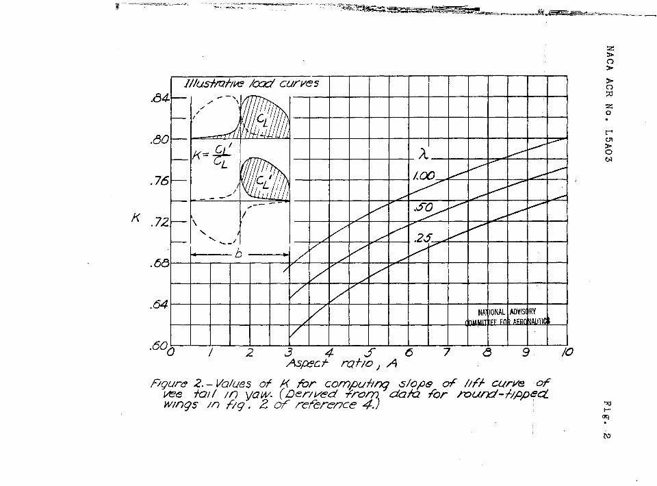
sum of changes In tail lift coefficient normal.to each tail panel when tail 1s yawed;equal and opposite span load distributionsoverlap so that cL# = KCLN, where values .
for K are pre~ented in figure 2
~“
..-— —— —
6
K
. .
k
aN
c%~
4
- NkCL ACR Na. L5A03..
ratio of sum of lifts obtained by equal andopposite changes In angle of attack of twosemlspans of tall to lift obtained by anequal change In angle of attack for com-plete tall (see fig. 2)
constant of proportionality
angle of attack measured in plane normal tochord plane of each tail panel, degrees
slope of tall lfft curve in pitch measuredIn plane no
r)
al to chord plane of each~LN
tail panel~
cqJ slope of vee-tall lift curve when lift andangles of attack are measu~d in planesnormal to chord plm”e”sof two tall panelswhile angle of attack of tall at Is held
.(.)
dCLl,’constant and tail”is sideslipped -
daN
T
slope of tall lateral-force curve measuredbcyt
(’)normal” to plane of symmetry —
bet,
~ (,/_)control-effectiveness parameter
Subscripts:
w. Wfng. .
t tail
h horizontal tail
v vertical tail
vee vee tail
e elevator
r rudder
—..
NACA hCR NO c L5AC)3
er elerudder. . . . . . ... .... . . . .. . . .. . ... ... . . .. ..
f“. flap”
7
-. .,.-. ..... ..... , .. ... ... . . ., . . . . . . . ...=
P,WJ~,a denote partial derivatives” of coefflcicnt~with respect to angle of sidesllp, angle“ofyaWj control-surface deflection, andangle of ettack,,reepectiv,ely; for example,
“i)cy “ “Cy =—P ?)?
Basic Assumptions
As indicated In reference 3, an isolated vee tallmay be considered a wing having a larpe amount ofdihedral. The basic assumptions usually made for a wingwith dihedral are used to derive fairly simple expres-sions for the stability, control, and control-forceparameters for vee tails. The sFan load distributions “- -,
!1.~computed by use cf lifting-llne theory for wings withno dihedral and no sweepback are assumed to be vali~ for ~wings with dihedral and are assumed to be unaffected by ,Interference at the point where the dihedral changes.The assumption is also made that, when the effectiveamgles of attack of the two panels of a wing withdihedral are changed equal and opposite mounts bysidesllpplng, the changes in lift coefficient normal toeach panel are equal and opposite in sign and are equalin magnitude to the changeq resulting from equal andopposite changes in angle of attack of the tws panelsof a wing with zero dihedral- The assumptions of coursebecome less valid as the dihedral increases.
In order to simplify the analysis further, thelongitudinal and directional characteristics are con- .sldered independently and the l!ft and hinge-momentcharacteristics are assumed to be llnear “in spite of thelarge control-surface deflections that are required withvee tails when full elevator and rudder control areapplied simultaneously. Considering the longitudinaland directional characteristics Independently and notaccounting for the nonlinearity in the various coeffi-cient curves results in Idealized solutions that must
I —------ —. —
.. . . .—. . .1
-.+“- .. -
be modified In practical applications. The degree ofmodification will of course depend on the characteristicsof the control surfaces and alrpler~eunder consideration.
..
The solutions devived herein are presented only to indi-cate the general appr~ach to the problem and to presentsome Idea of the comparative characteristics of vee andconventional tails! In the idealized case.
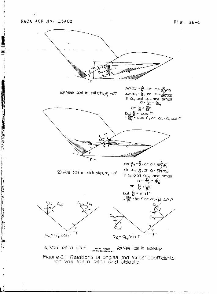
With these assumptions as a basi~, the followingrelationships were developed and are illustrated infigure 3:
(1) For small mgles of attack, the a~l.e of4&ttackmeasured In the plane normal to each panel of a veetall is equal to the an~le of attack measured in theplane of synmetry multiplied by the cosine of the taildihedral angle (fic. 3(a)); thus
a~ = at cos ~ (1)
(2) For small .&gle? of si~epllp, tkc chun~es inangle af attack measured in tfi,e,planes”normal to e~chpanel of the”vee..tail are equal and opposite in si~n
r sidesl.ipmultiplied by the&ad are equal to the an~le oisine of the tti. il”dlhedralangle (fig. 3(b)); tkus
aN = ~t sin r.
(2) :
. .
(3) The lift coefficient measured in the plane ofsymmetry i~ equal to the lift coefficient measured !nthe plane normal to each panel.of the vee tall multipliedby the co~ine of the tail dihedral anrle (fig. 3(c));thus
= CL,,CC)S ~c% . ‘,
.,
(3)
.
(4) l?hen the vee tail Is sideslipped, the “chancesin lift coefficient normal to each panel are equal andopposite in sign and the lateral-force coefficient of
NACA AOR No. .L5AO3 .
-,. ‘khevee tall..ls_eq.u8lcoefficient normal to
L b 9
to,thq sum of the changes in lift.each mnel of the””vee”tall multi-
;;l-~dby the she of the tail dihedral angle (fig. 3(d)) ;..
Cyt = C~f sin r (’4). . . .
Stability and Control Parameters
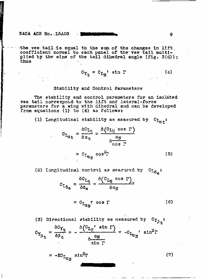
The stability and control parameters for an i.so~tedvee tall correspor~d to the lift and lateral-forceparameters for a wing with dihedral and can be developedfrom equations (1) to (4) as follows:
(1) Longitudinal stability as measured by c~t:
= cLa~TCosr(3) Directional stability as measured by
c% k:
(5)
(7)
~“
—. — -- .-

. .
.
10 3 NACA ACR No s L5A33
(4) Directional control as measured by Cya= :
= “%NTsin I’ ( !3)
The relation between the stability param~etersC%t “md
fcr vee tails nay be obtained asc% t
The relation between the
-KcL,aw sin%’
cy5r may be obtained “1.vllarlyas
... . .
=Ktanr (lC)
()ck~~’Values of K or — far variolla nspect ratios
ck~. . ..
and taper ratios are pre~ented in fi~ure 2. The valueswere obtained from extra~olation of values of K deter- .mined from figure 2 of r~ference 4 by graphic~lly -Integrating the complete load curves f~r li3~, inte-
grating the right-hand half of the load curve--mlnuz theleft-hand half, and taklr.gthe ratio of the two values,
. . .—
1
NAGA ACR No- L5AC)3 \
. . .. . . . ... .. Compar~.son of Stability ‘&d. ... .....
11
Control of. . ..-. .,,
Vee and Conventional Tails
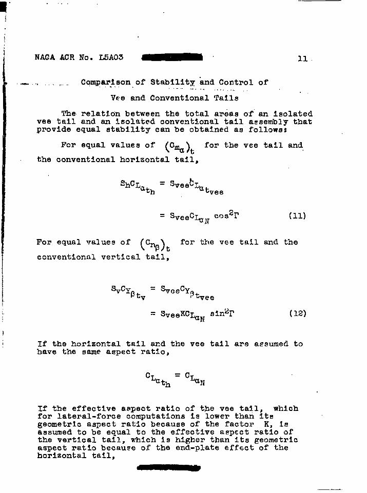
The.relation between the total areas of”an Isolatedvee tall and an Isolated conventional tall assembly thatprovide equal stability can be obtained as follows:
For equal values of(c%),
for tke vee tail and
the conventional horizontal tail,
= Sveeb~‘h%=th‘tvee
2r(11)= sveec~N cog
For equal values of C( %)
for the vee tail and thet
conventional vertical tail,
‘c%tv= %eecYptvee
= SveeKC~N sin%’ (12)
If the horizontal tall and the vee tail are assumed tohave the same aspect ratio,
If the effective aspect ratio of the vee ta~l, whichfor lateral-force computations is lower than itsgeometric aspect ratio because of the factor K, 1sassumed to be equal to the effective aspect ratio ofthe vertical tail, which is higher than its geometricaspect ratio because of the end-plate effect of thehorizontal tail,
. ... . .. . . . .. .. . .
12
—..
NACA ACR No, L5Ai3
—
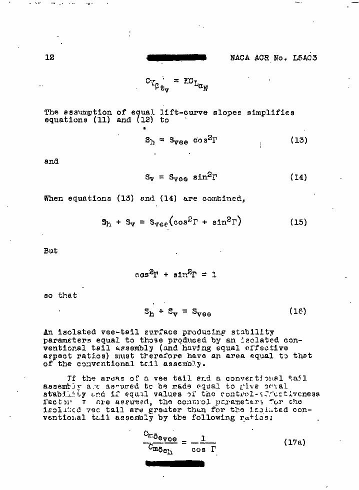
The assumption of equal lift-curve slo~es simplifiesequations (11) and (12) to -
●
s> = Spee COS21’ (13)
and
When equations (13) and (14) are cuJfihinecZ,
sh+q= svce(c092r + t3in21’) (15)
But
so that,“
‘h + Ev = Svee (16)
An isolated vee-tail surface producing stabilityparameters equal to thage pr@nced by an :?clated can-ventimal teil tissembly (and huv~ng equal effectiveaspect ratios) must tkerefore have an area equal to thatof the cmvcntlonal tcil assemb?.y.
%fj~v~e = 1—.—— ——
cI116eh(17a)
Cos r
NACACACR NOO L5A031
b
— .. ..md- . . . . . . . . . . . . . . . ~... ,., : “ - : - ,,:,”,.:-,:M.:-S,.
mUn
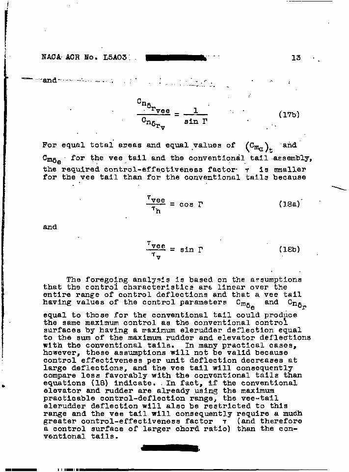
6‘vee = 1
cn6rV sin r
For equal total a~eas and equal values
....
. .
‘f (%),
13 “.
(171s)
.an~ “
cm6e “ . ..for the vee tail and the conventional tail assembly,
the-required control-effectiveness factor. T is smallerfor the vee tail than for the conventional tails because
T vee—=cOsrTh (1.8a)-
and
‘vee—=sinr (l~b)‘v
The forego@g anal~sls is based on the assumptionsthat ths control characteristics are linear over theentire range of control deflections aridthat a vee tailhaving values of the control parameters cm6e and Cn6r
equal to those for the conventional tail could producethe same maximum control as the conventional controlsurfaces by having a maximum elerudder de:l.ection equalto the sum of the maximum rudder and elevator deflectionswith the conventional tails. In many practical cases,however, thesa assumptions will not be valid becausecontrol effectiveness per unit deflection decreases atlarge deflections, and the vee tail will consequentlycompare less favorably with the conventional tdils thanequations (18) indicate. .In fact, if the conventionalelevator and rudder are already ,usi~p the m.ximumpracticable control-deflection range, the vee-tallelerudder deflection will also be restricted to thisrange and the vee tail will consequently require a mudhgreater control-effectiveness factor T (and thereforea control surface of larger chord ratio) than the con-vcmtional tails.

.—
14 ~“ “ NACA ACR Noo L5A03
Comparison of Control-Force Characteristics of
Vee and Conventional Tails
A ~eneral solution relating the control-force char-acteristics of vee-tail and conventional tail surfacescannot easily be obtained since, in the design of equi-valent surfaces of the two t~es, equal values of thelongitudinal or directional stability and controlparameters may be obtained by several variations of thegeometrical relationship between the two types of tail.‘Usually It will be impossible to obtain equal values of
(%)all the parameters C Cm6e~ ~cnp)t’
t’and Cn5
rfor the two t~es of tail. By considering tke longi-tudinal and directional characteristics independentlyand by making certain simplifying assumptions, however,expressions can be derived that relate the longitudinalor directional control forces for vee tails and con-ventional tails.
Elevator forces.- The elevator control forces of avee tail and a conventional horizontal tail can berelated by neglecting the directional stability andcontrol characteristics and by assuming equal values ofcmat’ Cmdes tail length, aspect ratio, and gearing of
elevator to control stick for the two tails.
For equivalent longitudinal stability and controland with the same aspect ratio of the conventional andvee tails, it has been shown (equations (13) and (19a))that the area of the vee tail is related to the areaof the conventional tail by cos21’ and that thecontrol-effectiveness parameters of the two typss oftail are related by cos I’. For the horizontal tail anda vee tail having the same aspect ratio, the followi~expressions may be derived from equation (13):
Ch
Cvee =Cos r
(2C) ‘
and
,.
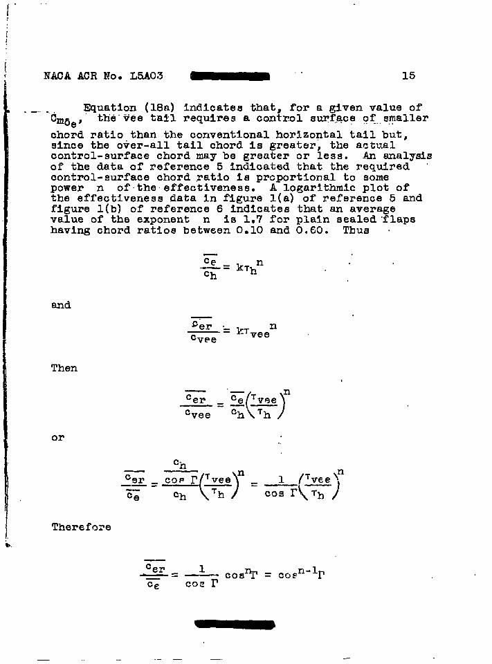
NACA ACR NO- L5A03 ~ ““ 15
-.. -. . ~uatlon (18a) indicates that, for a given value ofCmae # th’e”veetall requires a control surf.qcgof..s,rnaller
chord ratio than the conventional horizontal tail but,since the over-all tail chord is greater, the actualcontrol-surface chord may be greater or less. An analysisof the data of reference 5 indicated that the required “control-surface chord yatio 1s proportional to somepower n of”the effectiveness. A logarithmic plot ofthe effectiveness data In figure l(a) of reference 5 andfigure l(b) of reference 6 Indicates that an averagevalue of the exponent n is 1.7 for plain sealed ”flapshaving chord ratios between 0.10 and 0.60. Thus .
—
-’:’= k~hn
and-~er ._PT n—-cvee - vee
Then
“—
Cern
Ce
()
‘vee——Cvee = ch Th
or
There fore
.- .—— —. .-
16
.. i.,
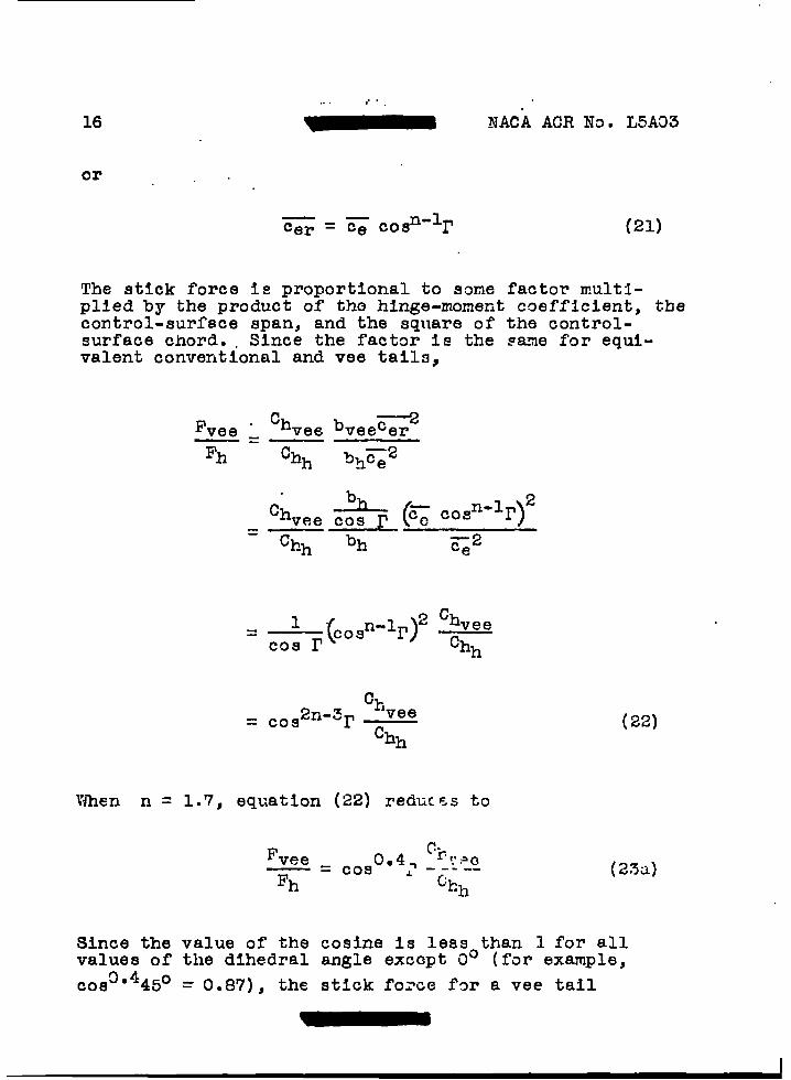
or
NACA ACR No- L5A03
(21)
The stick force 1s proportional to some factor multi-plied by the product of the hinge-moment coefficient, thecontrol-surfece span, and the square of the control-surface chord. . Since the factor is the same for equi-valent conventional and vee taila,
Fvee &Ch
vee bveecer——Fh Chh b~~z
Ch > (~~vee cos r COsn-1r)2
= Chh bh —2c~
1 (2 Chvee
= Cosn-%’) ~cos r
%= c0~2n-3r ~
Chh
When n = 1.7, equation (22) reduc~s to
(22)
(2?U)
Since the value of the cosine is less than 1 for allvalues of the dihedral angle except 0° (for example,
COS3’4450 = 0.87), the stick forue far a vee tail
.. ..
NACA ACR NOe L5A03
. —..
17 “
--should be less,.t~ ....f.a.na,n.equlvalent conventional tall”if the hinge-moment coeffic”leri~a-’a”r’eqtial. “Similarly,If the stick forces are equal, the vee-tall controlsurfaces generally do not need to be so ,closelybalancedas the conventio-nal surfaces.
Different as~~Jpt~ons In the analYSis will naturallylead to different results. some of which will be morefavorable to the vee tall- and some of which will,be morefavorable to the conventional tail. The present analysis,however, indicates that some reduction in control forceor amount of’balance required can be obtained by use ofthe vee tail.
Rudder forces.- In a similar analysis of rudderforces, it wac a~umed tk.attklemean chords of the twotypes of tail are equal and that, for the average case,the resultin~ increased aspect ratio of’the vee tailoffsets the end-plate effect of the h~riz,ontal tail onthe vertical tail and causes %lJ’ to be equal to
Cy( s) The result of this analysis wastv ●
F c~veevee . sinl*4r —
~ Chv(23b)
which again indicates that the vee tail can have lowercontrol forces or can require less balance for the sameforces than the conventional tail.
Limitations of Present Analysis
In the previously developed formulas relating thecontrol forces of vee and conventional tails, the ele-vator and rudder forces are considered separately and noaccount i~ taken of the fact that likelift and hinge-moment curves of actual control surfaces are linear fum-tions of angle of attack and control-surface deflectionfor only small ranges of these angles. In practicalapplications of vee ta$l.s,the simultaneous use of fullrudder and full elevator control will usually place oneof the surfaces at a deflection outside the linear range
— —— .
. . . -.. .. . ..
18 .. NACA ACR No, L5A03(:.....L,.1..-”
of lift and hinge-moment -characteristics. This condl-ti.onmay be avoided b“~“usi”~c,dntrol surfaces of largerchord ratio and smal:le~def-lections, The use of controlsurfaces of’larger chord ratio tends to counteract thedecrease In control farces previously shown posslblo Futthe smaller deflections requfred rake possible the useof a morq fa’mraple cantrol-stick flearln~, which mightresult In a net decreaqe In control force. Tke fir.alrenult will of course depen~ on the amolu~t ~f elevatorand ruddrr cor.tml required In the spectf’ic case ar.donthe ciegrceqf linec.rltyof the variou.q characteristicsof the particular control surfaces being consfldered.In many ceses these practical aspects af the supplicationnot cnly w1ll cancel the gain In control force shownpossible by use of the vee tail but also rrayevenincrease ths control force.
The precedin~ analysls, hcwever~ indicates that,since in the idealized case the vae tall provides areduction in cor~trol force ~r balance, ttl~choice ~~ atail for any given airplane cnn be made only after athorou@ analys!s of the requirements of cac% gppllcation.
The follawing formulas for t:levee-t&il stahllityand control parameters were derived by m~aifylrlg eql~a-tians (5) to (8) for the isolated voe tail.to aFpl;~toa vee tail installed on an airplane:
(24)
(25)
NACA ACR Noo L5A03 “-”
. . . . .,,..
.
cos 11”:.
When equations (24) and (25) are combined,slon for flndtig the dihedral requtred faris
rearranged i
. .. . . . (.35) y
. . (’27)
the expres-the vee tail
(2E)
Equations (24) and (25) nay befollowing expressions for the area required far the
to Rive the
vee tail:
sVee =—.
%
()c%t’
(29)
and
(30)
Equations (26) and (27) may be rearra~ged to give the
.
following expressions for the control-effectivenessfactor 7 required for the vee tail:
-
0
20
—.
NACA ACR Noo L5A03
CmaeT
‘-qt Lt——q Cw c%~ * ‘Os r
and
cn5.
(31)
(32)
Desl,qn Proced~re
Tha steps in desiqnlng a vee tall to producedesired values of the stcbllity and”control parametersmay be outlined as follows: .
(1) D6cide on rcqulrcd values of(Cma)ts[Cn?)ts
cM6e 8 and. Cnbr. TLe VPG tail probably should be
designed to procuce higher,values of cm6e .and .Cn6r
than the conventional ta~ls in crder that the elerudder “ “deflections can be kept In the linear ra~e of controleffectiveness a~ainst defl.ection~ Tkis point is dis-cusced more fully In the section entitled ‘}Generalllemarks.~t .. .
(2) Determine values of 11 from fig~me 2 of thepresent paper and values of “CT from figure 3 of
-Nreference 7.
helpful in designing for the power-off and windmlllingconditions.
(4) Determine I’ from equation (28).
..— .—. —. ... —- ,- ... ,,,. 1 nlln
.— --
q
,1
NACA ACR No, L5A03 -“ 21
..– ....... (5) Determine........ . .-., .,.,.,.,%-ee from aquation (29) or (30)..“..-..... ,,., - .. ..... ,,.-..,... ...- ... . .(6) Determine T from equat?ans (31) and (32). ““
(7) Substitllte the larger of the values of Tobtain~d from step (6) in equations (26] and (27) todetermine final values of %~e ~d CnOr. One of
these two values probably will be larger than necessarysince the two values of T determined frm equations (31)and (32) will’usually not be identical.
(8) Use the value of T from””step (7) with fig.ure l(a) of reference 5 to determine the required value
/“of —Cer Cvoe ●
Presentation of Lata
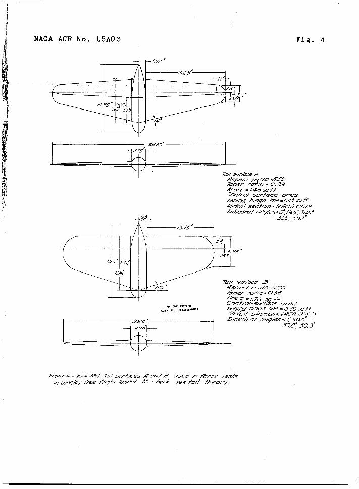
In order to FrOvide a check of the precedingdevelopmentt of a eimpllfied theory for vee tails, forcete~t~ of two i~olcted tail surfaces (tail ~urface~ A adB of fig. 4) with various amounts of d~hedral were madeIn the Lan~ley free-fll~ht tunnel., A test vas also me-deof tall surface D wit]]one tail panel ren.mvcd to rL-nu-late an isoleted vertical tail or the co:adltlonapprmclwxiby a vee tall with a dihedral angle of 90°. These d~taare presented in fig-ures5 to 9, & complete list offigures is presented in table I.
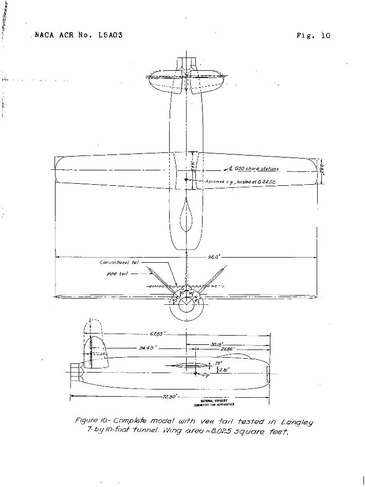
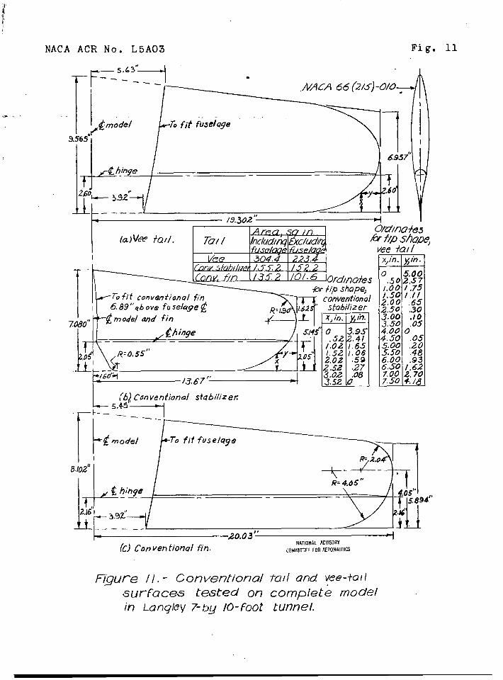
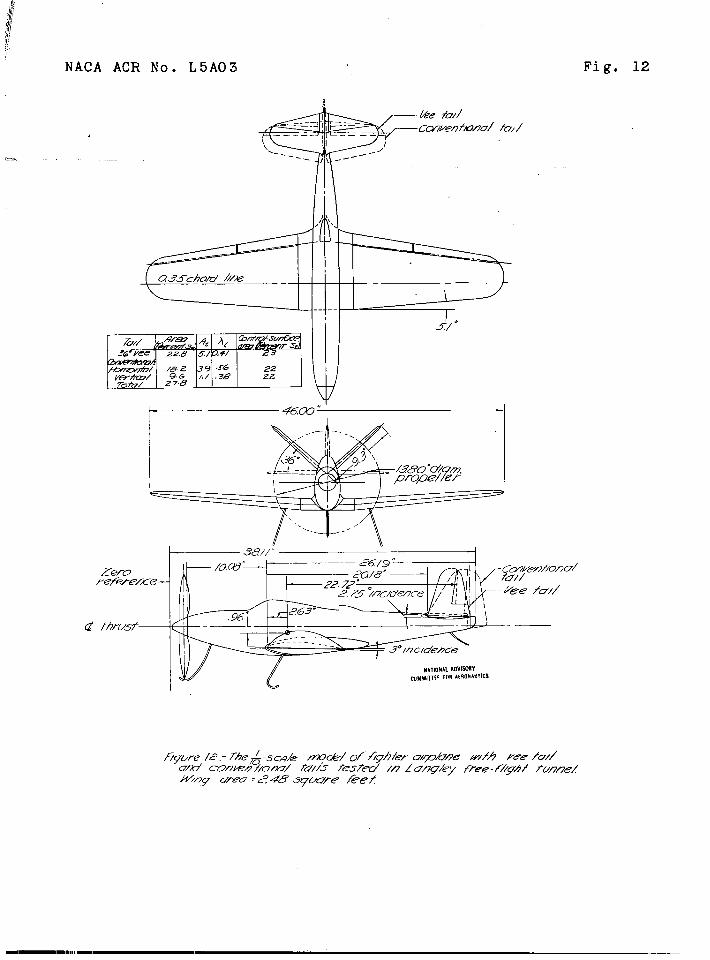
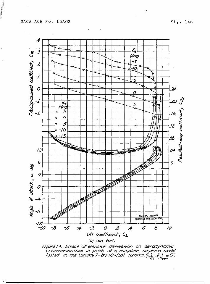
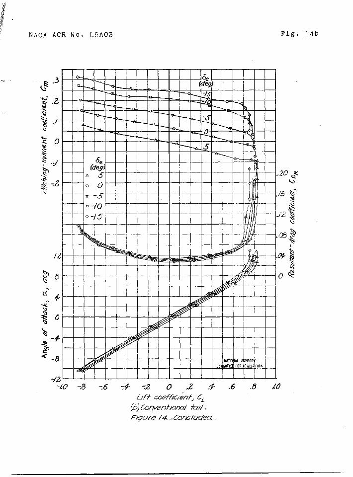
Some of the data cbtained in force tests of a com-plete airplane inodel (figs. 10 and 11) in the Langley.7- by 10-foot tunnel and in force and fll~ht tests of’ncomplete model of a fir~ter airplane (fig. 12) in theLangley free-flight tunnel are presented la fiqure~ 13to 20.
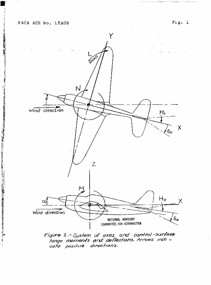
The results of the tests are presented In standardNACA coefficients of forces and moments. Tliedata arereferred to a system of axes illwhich tk.eZ-axis is inthe plane of symmetry and perpendicular to the relativewind, the X-axis is in the plane of symmetry and per-pendicular to the Z-axis, and the Y-axis is perpendicularto ths plane of symmetry. (See fig, 1.)
— - ..
—.-. .
22 NACA ACR Nom L5A03
Test “conditions
The force tests.of the two isolated tail surfaces Aand B were made in the Langley free-flight tunnel at adynamic pressure of 4.09 pounds per square foct, wlichcorresponds to an airspeed of’about 40 mlleg per hour.The test Reynolds numbers were.abont 199,0G0 for tailSluface A based on the tail mean geOmetriC Ck,ordof6-23 inches and 256,000 for tail surface I?ba~ed on thetail mean geometric chord of 8.01 inches. The effec-tive Reynolds ~umbers, bared on a t~r~ul~n~~ factOr of1.6 for the ~Ja~~l~y free-flight tunr.el,were about319,000 for tail surfa~e A and 410,000 for tail surface B.
The complete-model t“e~tsin the Langley 7- by10-foot tumnel were made at a dynamic pre~$ure of16.37 pounds per square foot, which corresponds to anairspeed of about 20 miles per ho-me The t~st Reynoldsnumber was about 733,000 based on t~~e~~iripr.esmgeometricchord of 12.04 inches. 3ecause of the turbu~erce factcmof 1.6 for the tunnel, the effective Repolds number wasabout 1,173,UO0.
None of the data have been corrected for the tarescaused by the motel srt<portstrut. Jet-boundar~ correc-tions have been applim to the s-nglesof attack, the
. . .
.
NACA ACR No, L5A03
drag coefficients, and the tail-on...,....,flclen-t’i--from-””te”stsh ‘the LQleTThese corrections wbre compute~ a~
Aa = 57.3(% + o.017c)#L (“de.g)
23 ~~
pitching-moment coef-7- .by 10-fo.ot t~qel~follGws:
jet-boundary correction factor at wing (O.119) .
total jet-boundary correction at tall(0.201 - 0.00083a)
model wing area (8.025 f%)
model mean geometric chord (1.003 ft)
tunnel crass-sectional area (69.59 sq f’t)
change In pitching-moment coefficient per degreechange in stabilizer setting as determined Inpresent tests
ratio of effective dynamic pressure over hori-zontal tall to free-stream dynamic pressure(assumed to equal 1.0 for this model) .
All corrections were added to the test data. Nocorrections have been applied to the farce-test. dataobtained in the LanEley free-flight tunnel, because thetunnel cross-sectional area C 19 large in comparisonwith the wing area of the models S and.the”.correctionsare negligible.
—. .—

—.. - —1
24
Teata
~“
of 1901st’edVee
NACA ACR No, L5A03
Tails
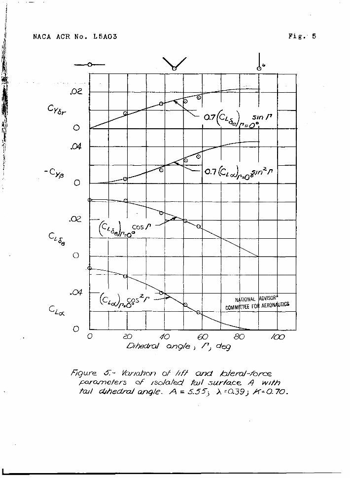
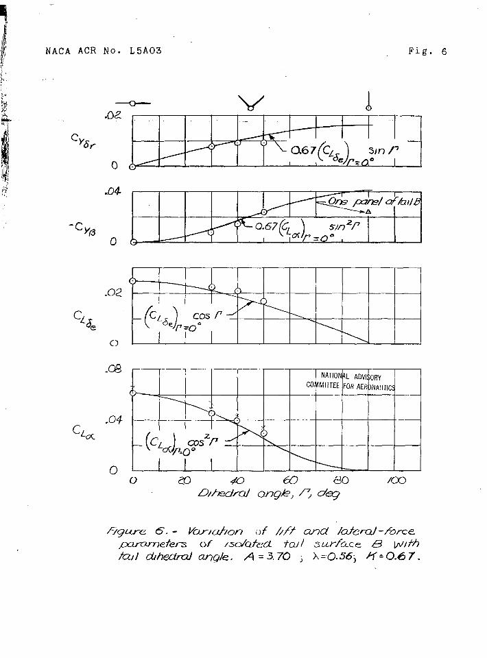
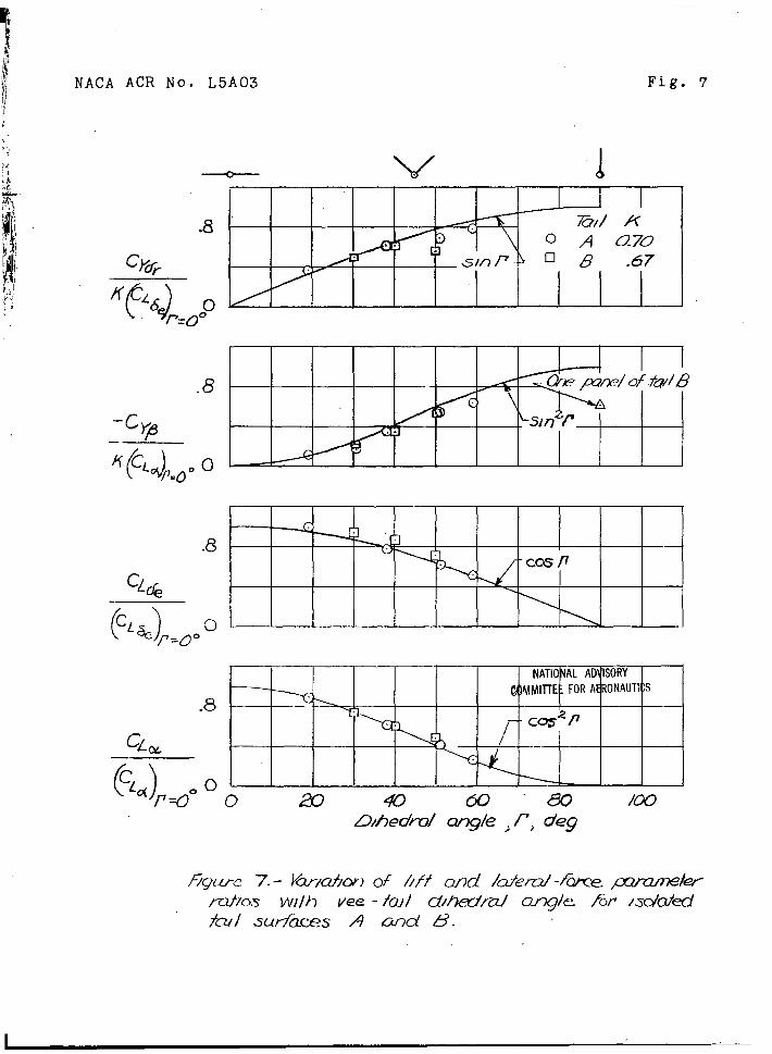
Results of tests of Isolated vee tcils are shown infigures”5 and 6, in which lift and lateral-force parame-
ters are plotted against dihedral angle for tall sur-faces A and B. The results are generalized as variationsof lift and lateral-force paiasmeter ratios with dihedralangle as shmm in figu~e 7. The data in figures 5 to 7indicate that the simplified theory developed In pre-ceding sections of’tbe present paper Is adequate. Theprincipal. discrepancies between the theoretical andexperimerltal results occnr for the lateral-force-curveslopes at dihedral angles greater than 4C”. Such Qresult is to be expected”sincc, as the dihedral angleapproa~hes 90°, the two panels gradually approach thecsndition of one ,panel of one-half the area and aspectratio. This conditicn 2s Illustrated in figures 6 and 7by the test poflnt at I’= 90° for one panel of ta!lsurface B.
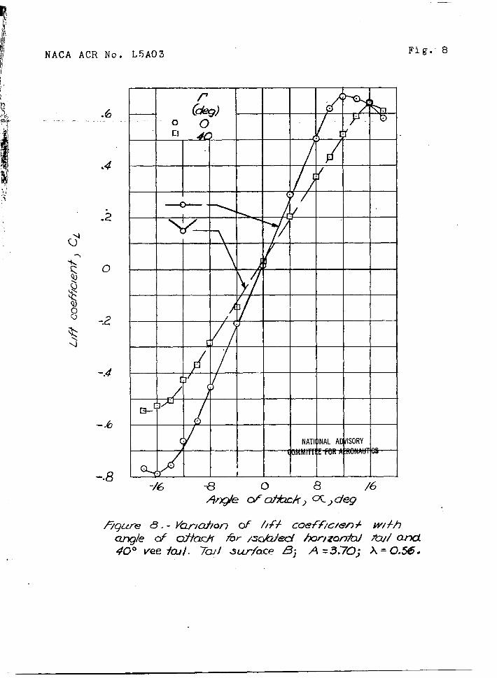
The data presented in fiGures G and 9 chow that theanflle~at which the lift and iateral.-fmce c-~rvesforthe vee tail depart from linearity are considerablylarger than the angles at which the curves for thenormal ta:l depart from linearity. This result is to beexpected, because for vee tails tiiesection ancle ofattack (or a~le of sidesl.lp) 1.ssnaller than the a~”lemeasured in (or normal to) the plane of synmetry 5T thecosine (or sine) of tb.edihedral a~le,.
The experlm.ental data of flguzzes 8 and 9 Giveresults similar to those obtained in the analYsi~J whichindicated that a vee-tail surface producinE stabilityparameters equal to tkose produced by a conventional.taila~senbly would have ~ area equal to the area of the C“o.n-ventional tall assembly. This result can be illustratedby the slopes of the curves as follows:
..
“Slope Conventional tall
m
40”3vee tail I
i).f240 (from flg. 8)
-.016 (from fig. 9) Iwhere all coefficients are based on the area of twotall panels. These values of C~ and CYP far the
4
.
-. —.—. —
NACA ACR’NO, L5A03 .\~f..”: 25 .
conventlonal:tafls are about 1.5.times as large as the...values,..fo.r“$~e,vee taiI, but.the conventional tailassembly EIISQhati”””l.”:5“tjn~s”””asmuch. area.-as--.t,ve,ee.e,tail because it.is made .up of three panels.,identicalwith the two panels of the vee tall? It therefore. .follows that, if this vee tail is scaled up so that itsarea is.equal to the total area of the conventional tallassembly, the stability parameters ”pPoducqd by the veetail w1ll be approximately equal to those produced bythe horiiontdl and vertical tails. ..,.
.,., .. ..
The experimental.”data”of figures 8 and 9.indicatethat, since = 0.048 (based on area of vertical tail)~Y@ .
‘d ‘%i~ = 0.~7 x 0.061 = 0.041, .ihe effective aspect
ratio of the vert:cal”tail was greater than” the effectiveaspect ratio of the vee”tail in sicbsl:p, 6ven though thevertical tall was tested in the isolated condition anddtd not have the beneficial end-plate effect of the hori-zontal tail. Tn?.F re~~~ltIs attributed to the fact thatthe geometric asp~ct r:..tioof the vertical tail was rela-ti’~elyhigher than USUU1 (one-halt’that of the vee tail) Iand to the fact tliatthe effective aspect ratio of thevertical ta~l wan Yigher than its geometric aspect ratio,pcselbly because of an end-plate effect of the streamlinefairin.g. In prwtical cases, the vert~cal tail and veetail probably will have approximately tbe same effectiveaspect ratio because the vertical tail will usually havean aspect ratio less than one-half that of the vee tailaIthou& it will benefit from the end-plate effect ofthe horizontal tail.
‘ For the ,isolated tail, no r~ductlon in total areaappears to result fdom the use of,a voe tail unless ahighereffecti.ve aspect ratio is uSed for the vee-tai.lsurfaces than for the conventional “tail sur~aces. Forthe-two complete models tested to date? the vee-tall.sur~aces have had much higher geometric aspect ratiosand probably higher effective aspect ratiog. For thefighter-airplane model tested Zn”the Lc@ley free-flighttunnel, for .ex”ample.;the values of.ge,ometric aspectr&tio were 5.1, 3.9, and 1.1 for the vee, horizontal,and vdrt”ical.tail surfaces, reqpec,tlvely. A’higheraspect ratio Appears to be the principal factor con-”tributirig to”’thdreduction in totdl tail area foundpossible for a vee tail and 1s of”~cburse not an inherentcharacteristic of a.vee”hail~ Partiof the reduction,
.
26,. NM2A ACR No, L5A03
however, mtght have been caused by the higher locationof the vee tail, which places it in a,region of lessdownwash pa,rtfcularly for high power conditions, or bythe shape of the vee tail, which places it away fromthe wake of the cockpit canopy.
.
Tests of Complete Models
Data from tests of complete models in the Langley7- by 10-foot tunnel and in the Langley free-flighttunnel are presented in figures 13 to 20. .
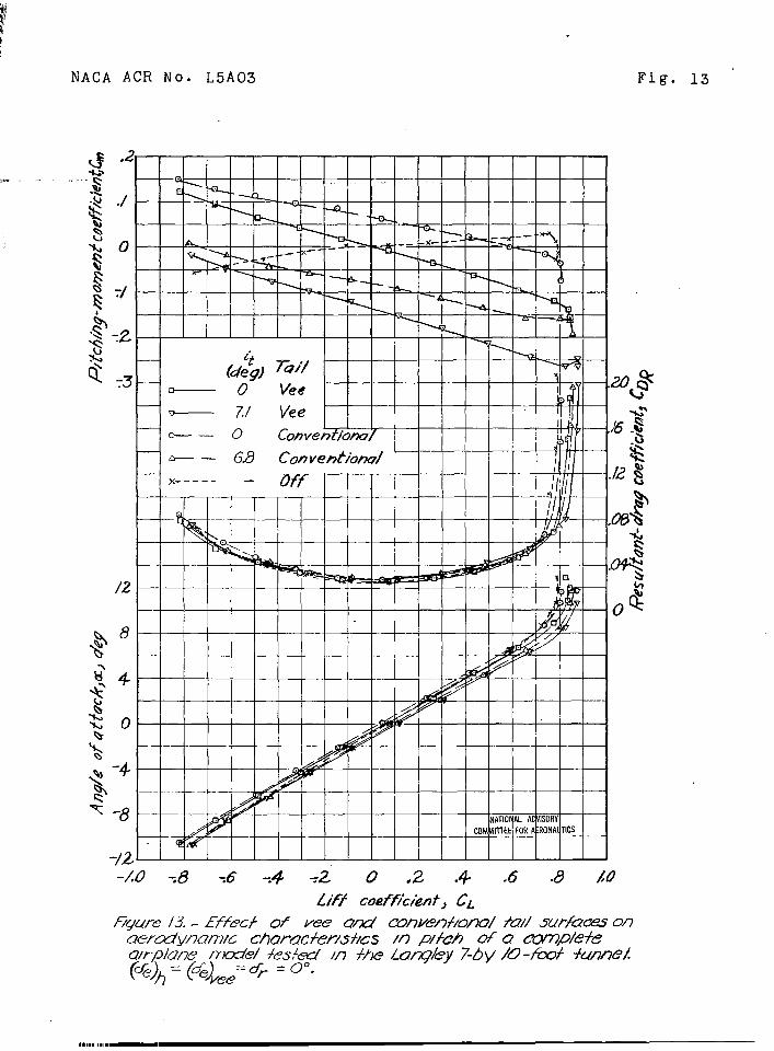
Tests in Langley 7- by 10-foot tunnel.- A three-VIew arawing of he complete model and details of thetall surfaces tested in the Langley 7- by 10-foottunnel are “shown in figures 10 and 11. In these teststhe only unusual veeult to be noted Is that the longi-tudinal stability contributed by the vee tail, whichfrom equation (24) should have been equal to thatcontributed by the conventional tail, was about 10 per-cent greater (figs. 13 to 16)0 ‘l?heincreased effective-ness was probably caused by improved tail-fuselagejunctures. Similarly, the vee tail was abaut 10 percentmore effective in yaw than a theoretical comparison ofthe two tails indicated.
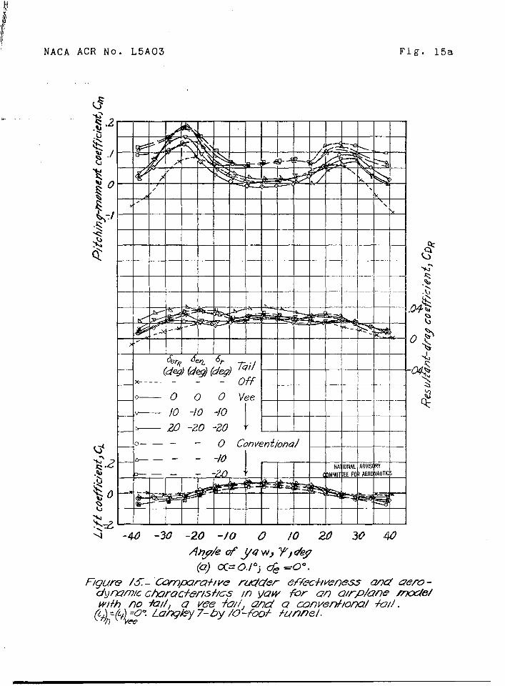
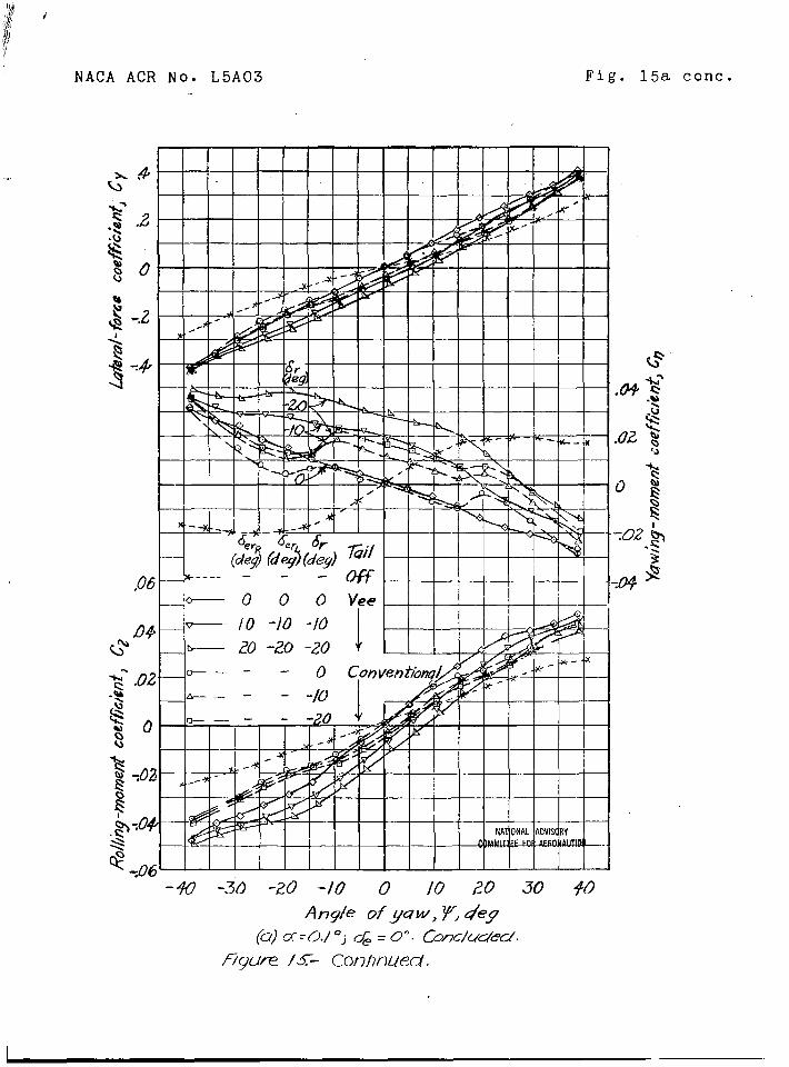
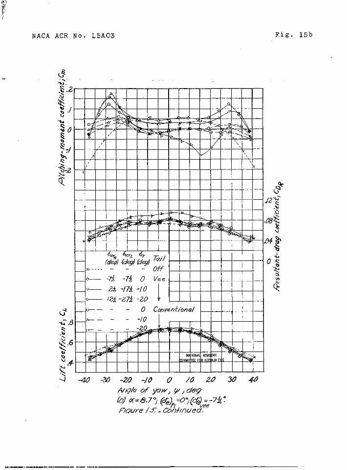
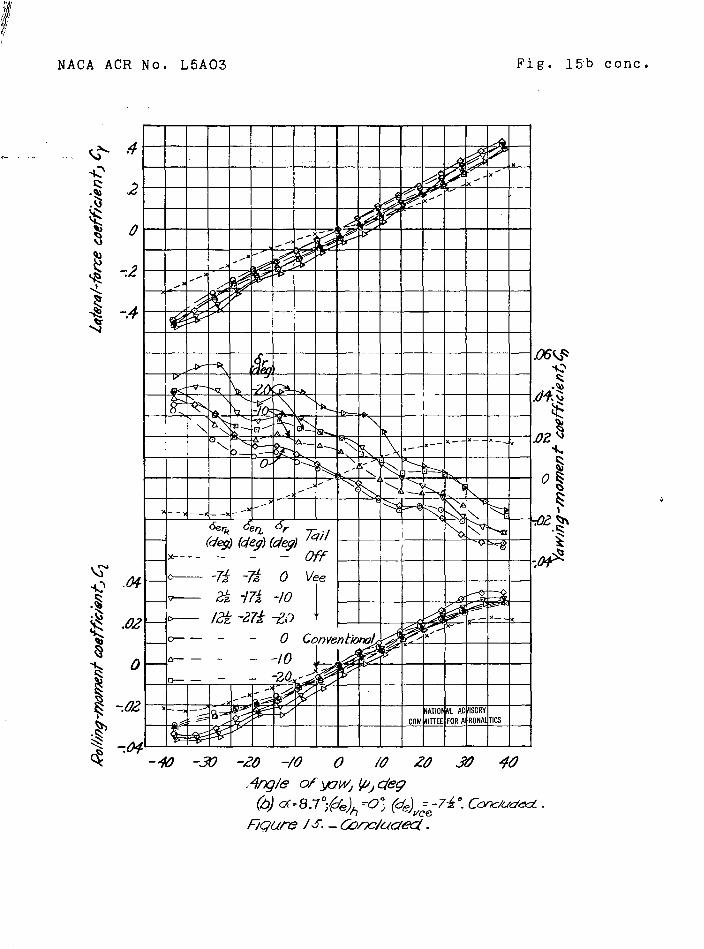
The effects of rudder deflection on the model withthe vee tail and with the conventional tail at high andlow angles of attack (a = O.1o and 8.7°) are presentedin figure 15. Some asymmetry of the pitchin~ momentsdue to the vee tail in yaw was noted when the elerudderswere deflected differentially as rudders. The.asymmetry,particularly at a = 8.7° (ffg. 15(b)), occurs becausein the positive angle-of-attack range the slope of thecurve of lift coefficient against angle of attack isgreater when a plain flap is at a large negative deflec-tion than when the same flap is at a positive deflection-Thus , since the effective angle of attack of the veetail varies with yaw and since the tail was already ata positive angle of attack, the left-hand half of thetail, which had a negative deflection, was operating ina range in which the slope of the lift curve was higherthan that for the right-hand half, which had a positivedeflection. The change In pitching moment with rudderdeflection at zero yaw was a result of simple nonlinearityin.the curve of lift aghinst deflection.

—.. .
NACA ACR NO, L5A03 b 27
The Cata of figure 15 also show that the ratio of.,.-,adv.erg.e.rolllng moments to favorable yawing moments ,
produced” by””’iiidd’dr””deflectlonis greater for the.vee..tail than for the conventional vertical tail.
Additional problems Involved in simultaneous opera-tion of the coritrols ape the change In elevator stickforce when a large rudder deflection carries one surfaceout”of the.linear range, and vice versa, and the possiblecha”ngein trim about one axis when large tab deflectionsare ““re-qtiredfor tr”im”about the other axis. The magni-t,u~eof all these effects will of course depend on .individual. airplane characteristics such as the amount .of control or trim required,’ the length of the linearrange of control-surface and tab characteristics, andthe relative magnitude of a given change in hinge-momentcoefficient when translated into stick or pedal force.
The curves for results of tests of the vee tail ingeneral are more ltegu?.arand are smoother than the curvesfor results of tests af the conventional tall, particu-larly at a = O.1O. For a = O.1O, the conventionalfin stalls rather abruptly at angles of yaw of +15° andthen re~atns effectiveness whereas tineyawing-msmentcurves for the vee tail form a relatively straight linefor values-of * up to *400. This characteristicresults probably because the section angle of attack ofthe vee tail is a function of”the sine of the angle ofyaw and thus the vee tail would be expected to stall atgreater angles of yaw than the conventional tail. TheInherent tendency of the vee tail toward later stallingis also illustrated in figures 8 and 9.
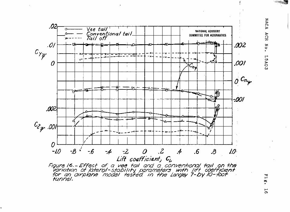
The plot of the ”lateral-stability and directional-stability derivatives In figiire16 indicates thatneither the vee tail nor the iionventional tail appreciablyaffects the variation of”these slopes with lift coeffi-cient; Ohe interesting point Is that the vee tail con-
1°tributed about 12 mdre”effective dihedral than the
conventional tail although. the values of cn~ and c@”#were app.roxititely equal for the two tail”s.... . . . ... . . .
Tests in Langley free-fli@t tunnel.- A three-v~ewdrawing of he complete “fighter~airplane model testedIn the Langley free-flight tunnel is shown in figure 12.Dimensions”of the 36° vee tail and the conventional tail
.,
—.—
28 NACA ACR Nom”L5A03
tested on the model =9 also given in figure 12. Themodel was tested with vee-ta~l dihedral angles varyingProm 32.4° to 45°.
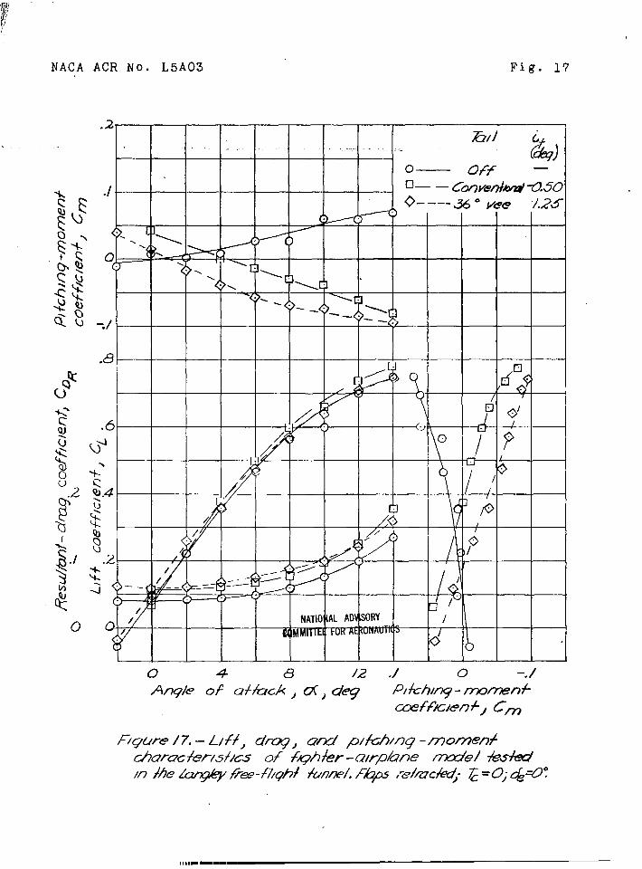
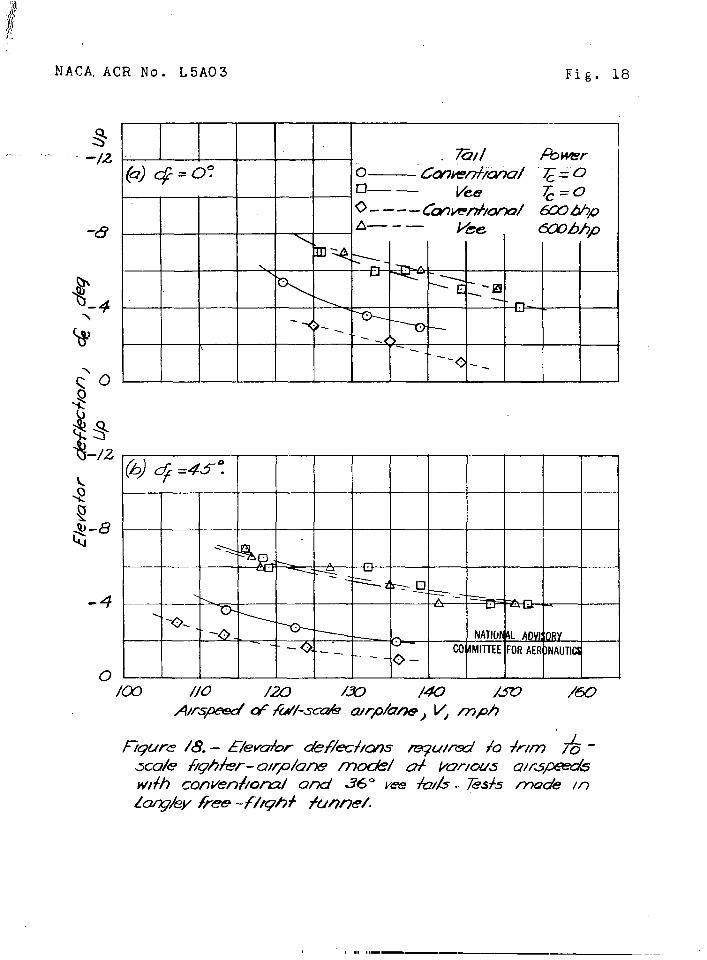
The results of force tests to determine the longi-tudinal stability characteristics of the model with theconventional tail and the 36° vee tail are shown infigure 17.. The data in figure 17 exhibit no unusualcharacteristics, anti the flight-test data presented infigure 18 provide another quantitative indication thatthe static longitudinal stability characteristics wereessentially equal with the vee and conventional tails.The vee-tail arrangement showed less change of trim withpower and flap deflection, probably because of its higherlocation. During the flights of the madel, the pilotcould detect no differences in the dynamic stability andhandlin8 characteristics with the two tails.
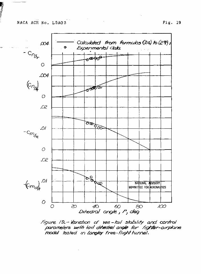
A summary of the stability and control characteris-tics measured in force tests of the various vee-taila~rangements is presented in figure 19. The scatter ofthe data in f:gure 19 is caused partly by the slightvariations in area, aspect ratio, and percentage ofmovable area for the different vee tails as well as indihedral angle. These results indicate fairly goodagreement between experimental and theoretical results
(%)except for the values of C at dihedral angles
tgreater than 36°. Similar results were noted previouslyfor the isolated-tail tests,
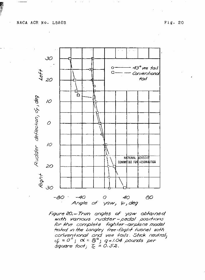
The fighter-airplane model was also tested in theLangley free-flight tunnel on a test stand on which it~as.free to yaw but was restrained in roll and pitch.An indication of the rudder-force-reversal characteris-
.. tics of the model with conventional and 43° vee tailswas obtained with this setup from the trim angles ofyaw produced by different fixed rudder deflections.The results of these tdsts are presented in figure 20.The test~ showed that with the vee tail the model wouldtrim only at fairly small angles of yaw even with fullrudder deflection. VJith the conventional tall, however,the model yawed to la~ge angles with left rudder deflec-tions greater than 13 - an indication that rudder-forcereversal or rudder lock probably exists for the airplanpwith the conventional tail. From the,sedata, therefore,rudder lock appears to “be less likely to occur w“ithavee tail than With a conventional vertical tall. The
— .—
.
.,
● ✎✎
NACA ACR NO, L5AC)3 29
previously noted facts that the vee tail stalls at ahigher angle of sidesltp and may reqtiire a controlsurface of smaller chord ratio than the conventional :vertical tail also Indicate less t“endency”tow”ard ‘“”rudder lock with the vee tail. “
GEW3RAL REMAilKS
Stability and Control Characteristics
The foregoing analysis of.vee-tail theory and testdata has indicated that a vee tail can have the followingcharacteristics relative to”those of a conventional tailproducing the same values of stability and cmtrolparameters:
(1) Approximately equal area unless the convent ionalvertical tall is in a bed canopy wake, unless the usuallyhigher location of the vee tail places it in a region ofgreatly reduced downwash, or unless thG vee tail has ahigher effective ~.spectrat?.othan the conventional hori-zontal and vertical tails.
(2) Possible inadequacy of controls and interactionof control forces when simultaneous full deflection ofboth control~ is required. This difficulty iS likely tobe encountered if the vee tail Is designed to give valuesof cm~e and Cn
6requal to those provided by a con-
ventional tail assembly. It is apparent that, if maximumrudder and elevator deflections of 25° or 30° are usedwith the canventtonal tails, elerud.der deflections of atleast 50°”or 60° would be required w$th the vee tail.At such large deflections, the elerudder would beope.rating in the nonlinear range of control effectivenessagainst deflection and might possibly be in the rangewhere the control effect”lveness per.unit deflectioneither remained const~t or decreased with increasingdeflection. One method of avoiding this condition is touse a large balanced elerudder surface that produceslarger values of & ~d Cn6P than the conventional-
Ctail control surfaces and.therefore produces “the requiredpitching or yawing rnoment~ with smaller deflections - notover a total of 30°0r 40° -with simultaneous full deflec-tion of b~th rudder and elevator controls.
30
. .
NACA ACR Not L5A03
(3) Possible interaction betweendirectional trimming when tabs are atdeflections.
longitudinal andfairly large
(4) Less tendency toward rudder lock.
(5) Possible reduction in control forces or inamount of balance required,
(6) More dihedral effect due to tail.
(7) Larger adverse rolling moments with ruddercontrol.
(8) Less change in trim with application of flapsor power because of the usually higher location of thevee tall.
Additional points not previously considered arethat the higlier location of the vee tall may decreasethe ground effect on the elevatar control required fortake-off and Iandlr.g and should also make it simpler tokeep the tail out of the spray for take-off end landingin flying boats.
Drag Characteristics
The data from tests in the Langley 7- by 10-foottunnel shown in figure 13 indicate a decrease of 0.0015in drag coefficient from.use of the vee tail; tests ofthe same model in the Langley two-dimensional low-turbulcnce pressure tunnel indicated approximately thesame drag reduction. For the model tested, a largepart of the reduction was probably caused by a decreasedfuselage-tail Interference with the vee-tail installatim.A vee tail, however, has only two fuselage juncturesinstead of three and some reduction in drag thus isusually obtained.
Compressibility Effects
For high-speed flight because the vee tail can beInstalled with a better fuselage-tail juncture, theeffects of compre,sslbility on tail drag should bereduced. This advantage, however, tends to be canceled
NACA ACR ~Oa L5A03 \
by the fact that, for vee tails, the‘will pr”obably be operating at higher
31
individual suriaceslift coefficients
for trim and-will almost certainly be canceled if thetail is so installed on top of the fuselage that asharp vee is formed at the juncture. The location ofthe vee-tail arrangement should place the surfacesfarther from the wake of the wing and canopy and therebyshould tend to reduce the possibilities of tail buffetingor roughness at high speed.
Spin-Recovery Characteristics
Tests in the Langley 20-foot free-spinning tunnelof a model of the same fighter airplane that was testedin the Langley free-flight tunnel indicated that thevee-tail arrangement had slightly better spin character-istics than the conventional tail assembly. The improvedspin characteristics might have occurred because, withthe vee tail, there was no horizontal surface to blanketthe vertical tail. The data presented in referenee 2,although inconclusive, indicated approximately the samespin characteristics for the two types of tail.
At present no general conclusions can be drawn con-cernin~ the relative merits of the vee tail and conven-tional tails for spin recovery. Although available testdata indicate that the vee tail may have better spin-recovery characteristics than the conventional tail, itis possible that if simultaneous full deflection of bothrudder and elevator is required for spin recovery thevee tail might have less desirable spin-recovery charac-teristics than the conventional tail assembly.
Structural Considerations
Manufacture and maintenance should be simpler forthe vee-tail than for conventional surfaces, since novertical tail surface must be manufactured, stored, orrepaired. The mechanism required to operate the controlsurfaces both as elevators and as rudders, however, issomewhat complicated and naturally tends to offset thisadvantage.
The vee tail, because of its configuration, mustcarry loads that do not contribute to the stability andcontrol. This factor will result in higher tail and
I
-. . . ... . .I
32 NACA ACR No- L5A03
fuselage loads in both pitching and yawing maneuvers,and Increased structural weight will be required tocarry the greater loads. “
CONCLUSIONS
The following conclusions were drawn from theresults of the analysis of available data on vee-tailsurfaces, from an extension of previously presentedvee-tail theory, and from general comparisons of variouscharacteristics of vee-tail and conventional tallsurfacesz
1. The ‘use of a vee tall will probably provide noreduction in area unless the conventional vertfcal tailis In a bad canopy wake, unless the usually higherlocation of the vee tall places it in a region of greatlyreduced downwash, or unless the”vee tail has a highereffective aspect ratio than the conventional horizontaland vertical tails.
2. A possible reduction In control forces (or inthe amount of control balance required) was Indicatedby the use of a vee tall, provided that large deflectionsof the control surface do not cause a large decrease inthe effectiveness and increase In hinge-moment coeffi-cient per degree deflection of the control surface.If large-chord control surfaces must be used In order tokeep the control deflections small, the control forces(or the mo~t of control bal~ce required) on the veetail are likely to be equal to or greater than those forthe conventional tall assembly.
3. The followlng advantages can be”obtalned with avee tail designed to provide the same values of stabilityand control parameters as a conventional tail assembly:
(a) Less drag because vee tail has fewer fuselage-tall junctures
(b) Less tendency toward rudder lock
(c) Higher location of tall surfaces,to reduce elevator deflection required forand landlng, to keep the tail out of spray
which tendstake-offin flylng-boat

I.
I NACA ACR ~No, L5A03 ~’ 33
take-off, and to reduce posslbllit$es of tall buffetingfrom the wing and canopy wakes in high-speed flight.... ,.,.
. . . . . . ,,,,~(d) Fewer ta’ilsurfaces to man~acttie ....-..
.
4. The following disadvantages tend to coun~e”ractthe advantages of the .vee tall: . . ,
(a) Possible interaction of elevator and ruddercontrol forces .. .
(b) Possible “interaction of elevator and ruddertrlmmln~ when tabs are at fairly large deflections.
(c) More complIcated operating mechanism
(d) Greater loada on tail and fuselage, which wouldtend to require increased weight .
5. The simplified theory of the vee tail is validfor dihedral en Ies up to about 40°.
~For dihedral angles
greater than 40 , measured directional stability andcontrol parcmleters were legs than indicated by theory.
6. The.relative merits of the vee tail and conven-tional tails for spin recovery have not been establishedbut it appeers that the vee tail should be at least asgood as the conventional tail assembly in this respect,except possibly in cases in which simultaneous fulldeflection of both rlulderand elevator is”required forrecovery from the spin.
1.,.;~: Langley Memorial Aeronautical Laboratory. National Advisory Condttee for Aeronautics
1Langley Field, Va.
i
i1
-—. .——.
34 “~ . NACA ACR No. L5A03
REFl!EUtNCES
1. Anon: The Rudllcki Vee Tall. Aircraft ‘mglneerl.ng,vol. IV, no. 37, March 1932, pp. -63-64.
2. Stephens, A. V.: The Vee Tall in Spin. Aircraft?%ngineerlng, vol. VIII, no. S3, Nov. 1936, p. 302.
3. Greenkerg, Harry: Comparison of Vee-Type and Conven-tional Tail Surfaces in Combination with Fuselageand Wing in the Variable-Density Tunnel. NACA TNNo. 815, 1941.
4. Pearson, Henry A., and Jones, Robert T.: TheoreticalStability and Cantrol Characteristics of Wingswith Various Arnomits of Taper and .Twlst.Rep ●
NACANoa 635, 193~o
5. Swanson$ Robert S., end Crandall, Stewart M.: AnalyBiaof Available Data on the Xffectlvenesa o“fAileronswithout Kxposed Overhang Balance. NACA ACRifo.L4E01, 29440
G. Ames, Milton B., Jr., and Sears, Richard I.: Deter-mination of Control-Surface Characteristics fromXACA Plain=F’lap and Tab Bata~ NACA Reps ~Om 721,1941.
‘7. Pass, H. R.:” Analy?is of Wind-Tumnel Eata on j)irec-tfonal Stab:lfty and Control. HACA TN No. 775,1940.
8. Recant, Isidore G..,and.~allace, Arthur R.: Wind-Tunnel Inve~tlgation of the Xffect of VerticalPosition of the King on the Side Flow in theRegion of the Vertical Tail. NACA TN Nu. S04,1941.
9. Gllruth, R. R., and Khite, M. D.: halysis and Pre-diction of Longitudinal Stability of Airplanes.NACA Rep, No- 711, 19410

I
I
t
—.—
Ii
ill,.
NAOh &CR No c L5A03 J 35
TABLE Ia- PRESENTA!I’IONOF RESULTSo
.
.
Model I Subject IFigure... ... .. . . . . .
None
None
None
Isolated tail surfaceeAand B
Isolated tail surface A
Tsalated tall surface B
Isolated tailsurface E
Isolated tail surface B
Complete model (Lsngle~7- by 10-foot tunnel)
Do----.-----
1,---- . .
IS@n convention forforces, moments, andsingles
Values of K “fordif-ferent aspect ratiosand taper ratios
Relation of angles andforce coefficientsfor vee tails
Two-view drawing
Variation of lift andlateral-forceparameters w?.thdikedr~.1 angle
Variation of lift andlater~l-forceparame’~ers withd?.hedral sr@e
Variation of ltft andlateral-force parame-ter ratios withdihedral single
CL against a forr = 0° (horizontaltail) and I’= 40°
Cy against Q for
r = 40° and r = 900(vertical tail)
Three-view drawing
Drawing of conven-tional and vee tails
NATIONAL ADVISORY COMMITTEE FOR AERONAUTICS .
.- —
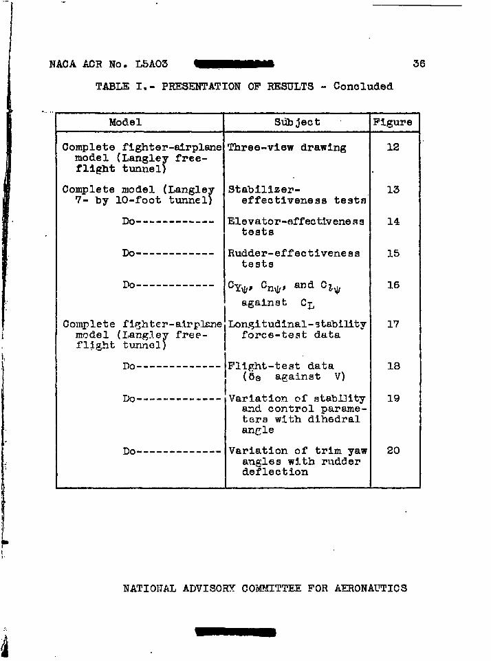
NACA ACR No, L5A03 - 36
TABLE I,- PRESENTATION OF RESULTS - Concluded
-.. , 1
Model Sdbject FiguTe I
Complete fighter-airplane Three-view drawing 12model (Langley free-fllght tunnel)
Complete model (LangleT
Stabillzer- 137- by 10-foot tunnel effectiveness test~”
Do------------ Elevator-effectiveness 14tests
Do----------.- Rudder-effectiveness 15tests
Po------------ CY~S ‘n~~ ad cl~ 16
I
against CL
Complete fiflhtcr-airplaneLon.qitudlnal-9tabillty 17model (Langl.e
rfree- 1force-test data
fl~ght tumni31
r)o-------------1Fllght-test dataI (be against V)
18
Do------------- ‘Variation of stability 19and control parame-ters with dih6dralanCle
Do------------- Variation of trim yaw 20angles with rudderdeflection
:...
iii
NATIONAL ADVISORY CO-MMITTEE FOR AERONAT’PICS
NACA ACR No. L5A03
Y
Fig. 1
M
--Kcc—
<
—(
ViZZZGKn
z
He ~Y~5....—–~\NATIONALADVISORY ~ &
I COMMIHEE FORAERONAUTIC
Figure i .- &y.skm d UXeZ Qni con+fol -surfooe
Am@ mw’?x?ds and de f/t?c?+ons. APmws /d/ -
CQtP pwI/) Ye c4/ret+/ons.
~ ----=.=a-_._. .=,... -? +m.e. .. ..
w---- . .
.84
.80
.76
K .72
.68
.64
.600 , ~ ~ ~ ~ ~ ~ ~ ~ ,0
Aspct rQt\o , A
F/gure 2. – values of K fir COm/)U+/~ 6/O/@ of \/f+ CUrVi? OfEC +CWI )~ yew. (Der/ved from do~ for mwz?’-+lppqdWings /n f/g . Z of reference 4)
zo.
NACA ACR No. L5A,03 Fig. 3a-d
.,—.
__— —
(b) Vee tail, in pltchj~t .oY
(c)Vee tail in pitch. NAIlOW ,DWRY (d Vee [ail in sideslip.OW+lnF[ IOF mO,,Au,lm
Figure 3.- RelaLions of angles and force” coefficientsFor vee tail in pitch and sicJesIip.
NACA ACR No. L5A03
bF”Fig. 4
/0”—,
To//.surfize AA!spec/ /-r7t/o -555Tapr rotjo=0.39Arec? . A48 s-qf+CW7tro/-surface aret7behind hjnge hne =043s~ f+A%-foilsecfmn -NMC,9 00/2D/h&m/ uq/es=O~/95,03&8”
5[5.”59./ 0
r-7rF--’’”’l
m“+e~. L78 Sq f+Con/ro/-5urface Qr..o
&h)zz7 binge Ate. 0.50 sq f+AZrfol/ s~ci+m .N,4cu 0009D1/?edru/ ung/es-O,O300°
338; 50.3°
I
figure 4.- Xsdofi 70// 56.rfoces ,9 ffti B used /n Force /ecifs
m Lan@%’ ~ree - f/@/ ?&z& /0 CA-CA- fee-&I/ /h eory.
j1
}/
/Ii NACA ACR NO. L5A03 Fig. 5
..
%r
- Cy..
cL&e
n v.02
o
.04
0
.02
0
.04
o
1-~) NACA ACR No. L5A03i~~
,,
Fig. rj
C“Je
cLa
.02
c)
.@
.04
0
-( )CLA Cos f 1‘F=o”
————-.————.
INATIONIL AOVl~ORy I
ColIIMIITEEFOR AERI)/A(lTIC:(>
.,
$’1 r;
-( )CL coszf’ /
d/7=QQ \
c) a 43 m 80 /03D//%cird ongk, P, dq
NACA ACR No. L5A03
}
v
Fig. 7
()cL& of=o”
~~(k /@m/of .LWB
()cLd o
f =0° o 20 w 60 &@ /00
NATIOVAL AD\ISORY
clMMlllE i FORAERONAUTI:s
t
.6
.4
, />’:’:’+
.2
0
-.2
-.4
-. 6
-.8
-
1 \
%’
//]/
c
E-”
NATIONAL ACUISORY
-/6 % o 8 /6
Fig. 8

NACA ACR No. L5A03
.8~Q// 8 A
,. (qft)o 40”we /.7% 3.70
.6 cl—— VertiCaJ.89 /85
.4
ok
- .22Q)\$
:QoQ-l?$~ ..2.
$ r
NATIoNALAJVISORY
-30 -20 -/0At@e
hgum 9.- Vdr’ldlonWI ih CW@e of JAQW
(s/t@e gad d fzl
o /0 fm “20
Ofyw, v)oq
Fig. 9
of ta}l /b#em/ -fot&e cc&%cien*for conventloncd ve@Icaf twl
surface B) Q.net ~ 0 vee +cuI
(iall Surface 8). h= O.56.Vt?r+lcol Cmd M?(9 +c?//sSpQn, Uzd /m?c?r7 Chofu’fbct? B.)
ACR”NO, L5A03
--5Q
/“- ,.. -_-_-—.-..=—
1.
,----
I
;
.“
I --——
!1
,
—— — _—_. .0,
1.
Fig. io
LI.-+
I>
Lflumed c.~, Jocafedat O.2,Z5C
I
L-u
—
~$ Q50ch.rdst.tiO.$— —— .— __
Conventional to,l, 1
Yet? toil
I
.-.,/ ‘,
//;
v
L
lr’————— -_----4
Ftgure /0- Compkh mode/ with vee ?aI/ fe>feo’ In Lung/e~
7- h,y /o-foo+ funnel. iV/ng ~reu=60%5 zquffre fee t.
NACA ACR No. L5A03 Fig.
[
p:- ●
~1.NACA 66(2/5]-0/0.
=1
I
.{@mode/ ?2fit fuselage
9.565
~,
6.957”
&@flge — —
z~”b 3,9.2’”-1
Y
ti
.6o 1
—.—— ./9.302 “
P—___
~1—-1
~model TO fit fus ehge
8./02”
&4~
,, ? 4
~ y2,0# ,
t @9eR=4.05’0
f
_ .05”
Y ‘1-l
s894”
2.16”13.9L’ .6”
j.——— ——-20.03”
(C)ConventionulfineNATIONAL AOVISORY
COMMITTEE FOR P,ERONAUIICS
11
Figure II. - C or7vef7[fonal fatl and vee-+oIIsurfaces te6ted on complete modelin Lanqby 7-by lo-foot tunnel.
NACA ACR No. L5A03
—CmFenfmflu/ k71/I\
----
/ ‘-1‘-y,1,,/ ‘ .
Q 35cho/D’ ~m _
. . . .I
/b//36- vee “
vT~f9%i~/ 27.8
-5+o
~ 4=X7“ ‘
NACA ACR hiOo L5A03 Fig. 13
+.. . -.
ACR NO. L5A03 Fig. 14a
.4
IJ .3
-/;
NACA ACR No. L5A03 Fig. 14b
NACA ACR No. L5A03 Fig. 15a
>..
;’.2
.5&l~
-40 -30 -20 -}0 (7 /0 20 30 40A.y/e d ~q w, Y, deg
NACA ACR No. L5A03 Fig. 15a cone..
.06 ‘e”“:RFFFHTR
i
~o 00~ 10 -lo -10
~ 20 -20 -20*— -- 0A—---- -/0*— -- -20
..—--
.—-40 -38 -20 -10 0 /0 20 30 +0
Angle of yaw, y, deg
(U) ~=O.l “j~ = OO. Cone/uded.
f7ym2 /S ConW2wcY.
NACA ACR No. L5A03 Fig. 15b
>
.4
-Q -40 -M -20 -/0 6’ /0 2(9 30 44
-,,,“...-. , , .,,----. !.. .!.. ——!- ..--, . . . .
NACA ACR No. L5A03 Fig. 15b cone.
ETTtiiil, ,
Q-1--’ I
1--1 &$ cferL 4 I
I
(&d(ded(ded ‘ii’
.&
.02?
o
76??
-04
.4L@ of~wlp,deg
@ a=8.7:@e)h ‘o; @)&-74°. cCb%/udad-fiqure /.5 – Cuzk6’a2’.
I
●O2 ~Vee tail ‘
I I v
L— Con vent..onq} toilNATIONALADVISORY
----- Gil offCOMMITIEEFOR AERONAUTICS
w
.0/ “% ~ -I
W 0 — —. ,, — + — - — ~ ~
- -— -- -- __ -- . .- — x- --, -x - - -- x--- - -x- ,---A —--- ~--- - --- ---- . -x- -- _~ _ _--
x- - -xx- - *. .
0 -“T‘-.,x>!\Gv//
- b , .-..w Y“ -+—X4
m
\-x------x- ---- ..*- --- x--- -- -x.
x~ .K /x
f)/’
m?
.001
.’%1-m●
NACA ACR No. L5A03 Fig. 17
0
&// “?&)o— off —
J ~ ‘cl— — C@4e/7iti7250
I I
1
I I LL-4°-l---’?eT’e?-231
‘T’’?’-W23!! I I I I I—I I I I ‘i’ ~
+-tt-iA*12”4// I I I l~ljl?t I,, \
u I
oI ‘
\ ,/ ,1,
I I I I b I \& Al I I// I /4) Ill / I I
I I LAO? I AIi I I II
-
I I UNATlll AL AD SORY I Pi‘1
I II 1
MMI
III 1 I
I
/
~J/),,J’.
NACA. ACR No. L5A03 Fig. 18
~
>... ._-/2
-&
+!’_+G
‘T7a/ %4@??-
@?)@=a o’ “Cmben+ai%ii ~= o—. Vee g=o
z - –-– Cmww+zmo/ &D&pA—-— Vce &Obhp
A .
>-
i > :’ ❑
13-- -
. . --.
\ ‘.=-,
--
Km //0 /a /. /42 /372 /50A/rs~ & fdk=~ orpbe, V, mph
F19ure /8. – +E/evdor ab%mkms ~ulraz’ fo #../m 0-Jcok fighkr- a/r#am mocW u+ kmous arspeedswI#/? conven{/orn/ und 36” vie bb. ZWs mode InLcn#eY kee -f//qh+ fwvw/.
, ., ,,- .,——- . . ..__ -....____
[
j
/!/.~i
NACA ACR No. L5A03” - Fig. 19
.Q94..Z .—
- %dr
o
-m?
(~C*
o
.02
-0/- cm
cf~
o
.02
-taJ.01
cm
o
.I
~ ~
— ~
~ \\
c Nt(IONALADVISORYCOMMIT‘EEFORAERONALTICS
\
NACA ACR No. L5A03
. .
/0
0
/0
20
\
Fig. 20
rElzo 413°u?e +0//o— — Cm ven+mm
+0//
-&o - .& o 40 &o
Ang/e of yaw, p, deg