Embed Size (px)
Citation preview
Common Mode Rejection Ratio
www.ustudy.in
Introduction
The common-mode rejection ratio (CMRR) of a differential amplifier
(or other device) measures the tendency of the device to reject input
signals common to both input leads.
A high CMRR is important in applications where the signal of interest
is represented by a small voltage fluctuation superimposed on a
(possibly large) voltage offset, or when relevant information is
contained in the voltage difference between two signals.
www.ustudy.in
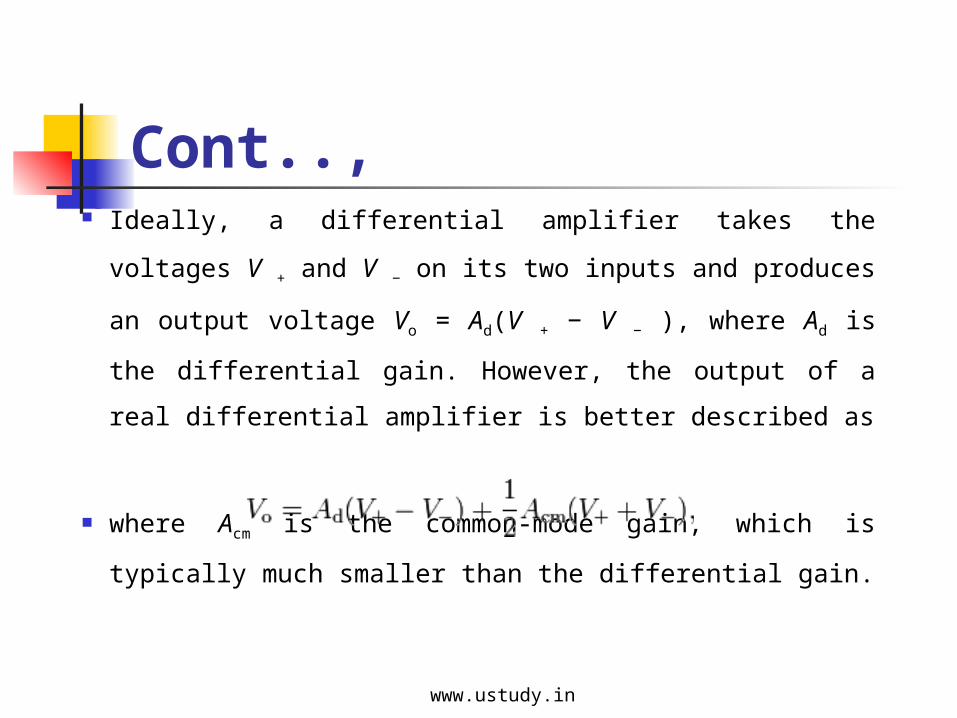
Cont.., Ideally, a differential amplifier takes the voltages V + and
V − on its two inputs and produces an output voltage Vo =
Ad(V + − V − ), where Ad is the differential gain. However,
the output of a real differential amplifier is better
described as
where Acm is the common-mode gain, which is typically
much smaller than the differential gain.www.ustudy.in
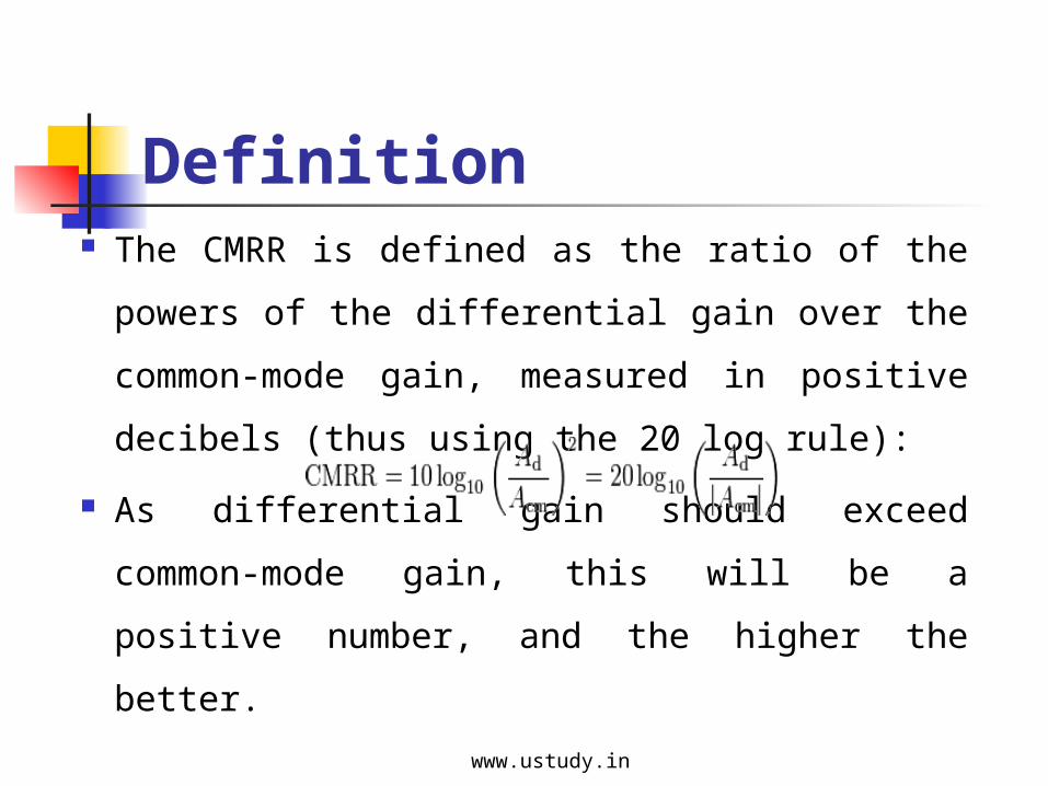
Definition The CMRR is defined as the ratio of the powers of
the differential gain over the common-mode gain,
measured in positive decibels (thus using the 20 log
rule):
As differential gain should exceed common-mode
gain, this will be a positive number, and the higher
the better.www.ustudy.in
The CMRR is a very important specification, as it indicates how much
of the common-mode signal will appear in your measurement.
The value of the CMRR often depends on signal frequency as well,
and must be specified as a function thereof.
It is often important in reducing noise on transmission lines. For
example, when measuring the resistance of a thermocouple in a noisy
environment, the noise from the environment appears as an offset on
both input leads, making it a common-mode voltage signal.
The CMRR of the measurement instrument determines the attenuation
applied to the offset or noise.www.ustudy.in
Measuring Common Mode Rejection Ratio
Common-mode rejection ratio can be measured in several
ways. The method shown in Figure below uses four precision
resistors to configure the op amp as a differential amplifier, a
signal is applied to both inputs, and the change in output is
measured—an amplifier with infinite CMRR would have no
change in output.
The disadvantage inherent in this circuit is that the ratio match
of the resistors is as important as the CMRR of the op amp.
www.ustudy.in
A mismatch of 0.1% between resistor pairs will result in a
CMR of only 66 dB—no matter how good the op amp! Since
most op amps have a low frequency CMR of between 80 dB
and 120 dB, it is clear that this circuit is only marginally
useful for measuring CMRR (although it does an excellent job
in measuring the matching of the resistors!).
www.ustudy.in
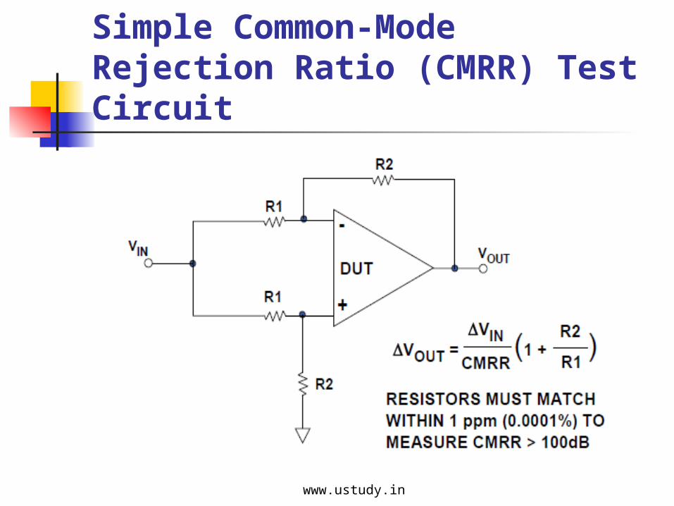
Simple Common-Mode Rejection Ratio (CMRR) Test Circuit
www.ustudy.in
The slightly more complex circuit shown in Figure below
measures CMRR without requiring accurately matched
resistors. In this circuit, the common-mode voltage is changed
by switching the power supply voltages. (This is easy to
implement in a test facility, and the same circuit with different
supply voltage connections can be used to measure power
supply rejection ratio).
www.ustudy.in
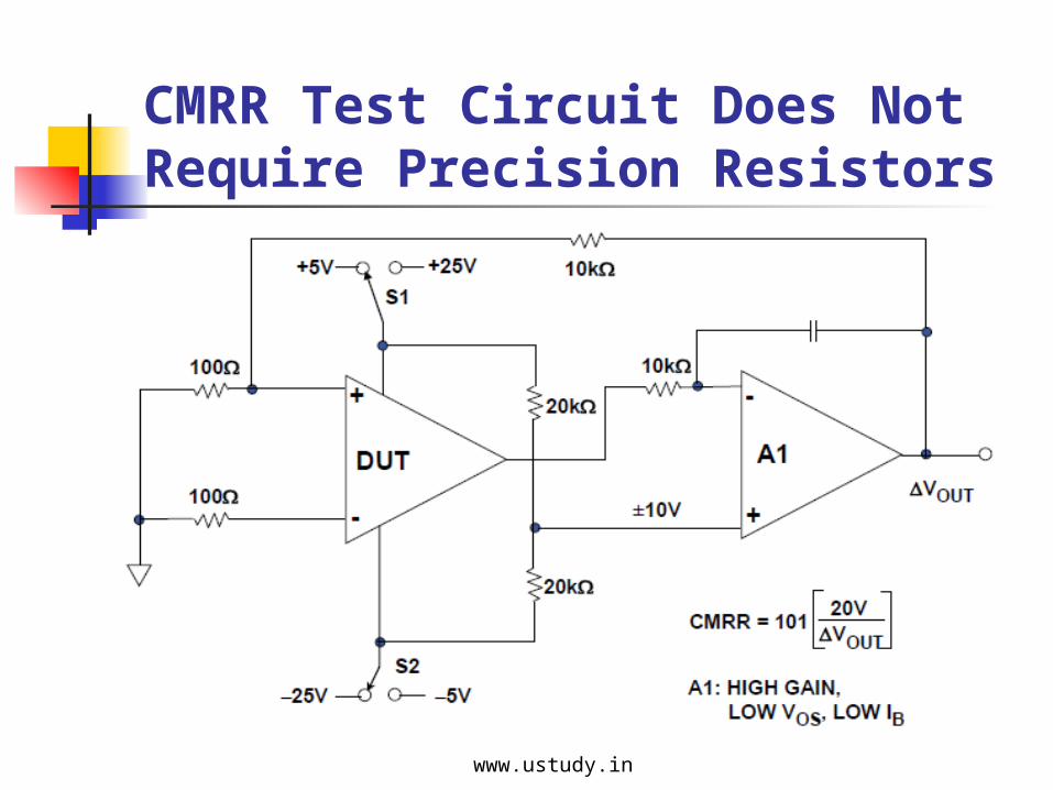
CMRR Test Circuit Does Not Require Precision Resistors
www.ustudy.in
The power supply values shown in the circuit are for a ±15 V
DUT op amp, with a common-mode voltage range of ±10 V.
Other supplies and common-mode ranges can also be
accommodated by changing voltages, as appropriate. The
integrating amplifier A1 should have high gain, low VOS and
low IB, such as an OP97 family device.
www.ustudy.in
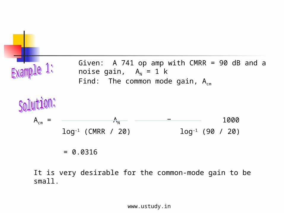
Acm = AN = 1000
log-1 (CMRR / 20) log-1 (90 / 20)
= 0.0316
It is very desirable for the common-mode gain to be small.
Given: A 741 op amp with CMRR = 90 dB and a noise gain, AN = 1 k
Find: The common mode gain, Acm
www.ustudy.in
Common-Mode Rejection Ratio (CMRR)
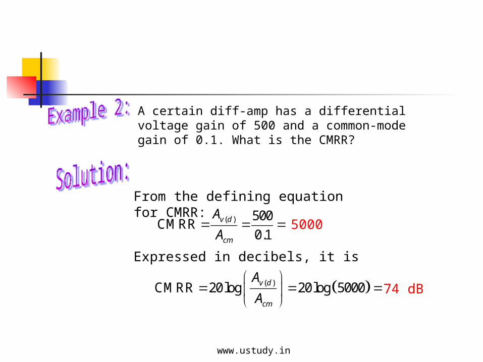
From the defining equation for CMRR:
( ) 500CMRR
0.1v d
cm
A
A
Expressed in decibels, it is
( )CMRR 20log 20log 5000v d
cm
A
A
A certain diff-amp has a differential voltage gain of 500 and a common-mode gain of 0.1. What is the CMRR?
5000
74 dB
www.ustudy.in
Common-Mode Rejection Ratio (CMRR)
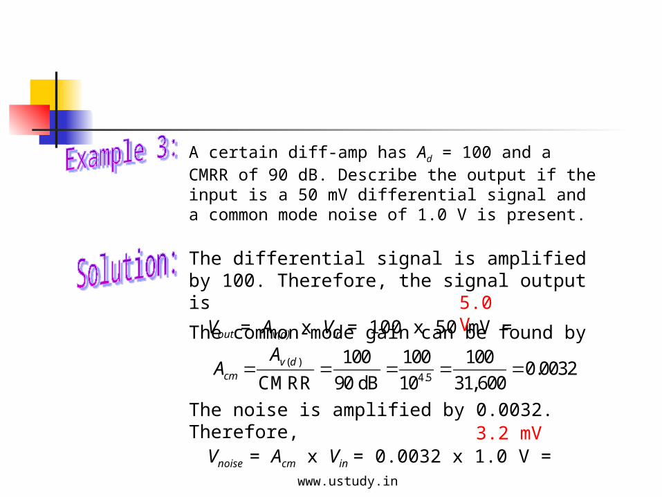
The differential signal is amplified by 100. Therefore, the signal output is Vout = Av(d) x Vin = 100 x 50 mV =
( )
4.5
100 100 1000.0032
CMRR 90 dB 10 31,600v d
cm
AA
A certain diff-amp has Ad = 100 and a CMRR of 90 dB. Describe the output if the input is a 50 mV differential signal and a common mode noise of 1.0 V is present.
The common-mode gain can be found by
The noise is amplified by 0.0032. Therefore, Vnoise = Acm x Vin = 0.0032 x 1.0 V = 3.2 mV
5.0 V
www.ustudy.in
Quiz
1. When two identical in-phase signals are applied to the inputs of a differential amplifier, they are said to be
a. feedback signals.
b. noninverting signals.
c. differential-mode signals.
d. common-mode signals.
www.ustudy.in
Quiz
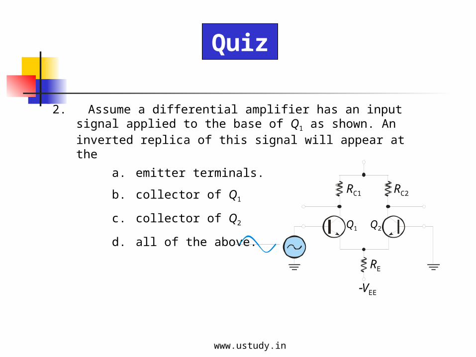
2. Assume a differential amplifier has an input signal applied to the base of Q1 as shown. An inverted replica of this signal will appear at the
a. emitter terminals.
b. collector of Q1
c. collector of Q2
d. all of the above.
RC1 RC2
RE
VEE
Q1 Q2
www.ustudy.in
Quiz
3. A differential amplifier will tend to reject
a. noise that is in differential-mode.
b. noise that is in common-mode.
c. only high frequency noise.
d. all noise.
www.ustudy.in
Quiz
4. The average of two input currents required to bias the first stage of an op-amp is called the
a. input offset current.
b. open-loop input current.
c. feedback current.
d. input bias current.
www.ustudy.in
Quiz
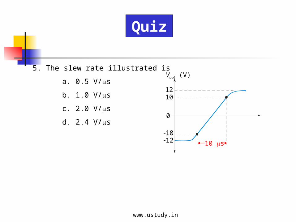
5. The slew rate illustrated is
a. 0.5 V/s
b. 1.0 V/s
c. 2.0 V/s
d. 2.4 V/s
Vout (V)
1210
1012
0
10 s
www.ustudy.in
Quiz
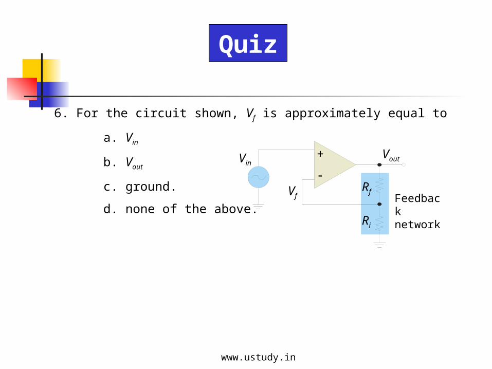
6. For the circuit shown, Vf is approximately equal to
a. Vin
b. Vout
c. ground.
d. none of the above.
+
Feedback network
Vf
Vin
Rf
Ri
Vout
www.ustudy.in

Quiz
7. For the inverting amplifier shown, the input resistance is closest to
a. zero
b. 10 k
c. 2 M
d. 8 G
+
Vin
Rf
Ri
Vout
150 k
10 k
www.ustudy.in
Quiz
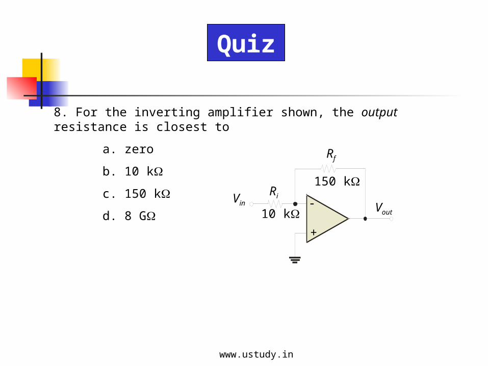
8. For the inverting amplifier shown, the output resistance is closest to
a. zero
b. 10 k
c. 150 k
d. 8 G
+
Vin
Rf
Ri
Vout
150 k
10 k
www.ustudy.in
Quiz
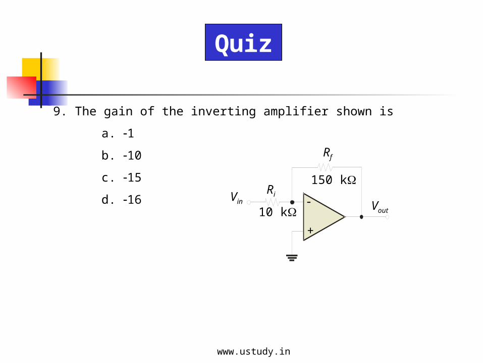
9. The gain of the inverting amplifier shown is
a. 1
b. 10
c. 15
d. 16
+
Vin
Rf
Ri
Vout
150 k
10 k
www.ustudy.in
Quiz
10. A voltage follower has
a. current gain.
b. voltage gain.
c. both of the above.
d. none of the above.
www.ustudy.in
Quiz
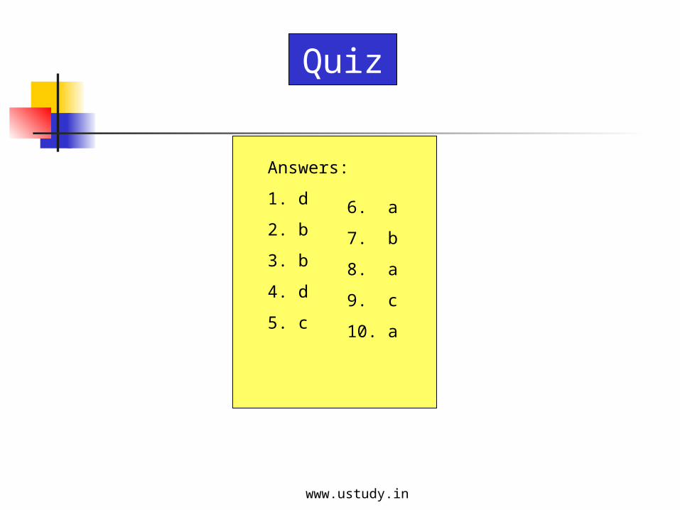
Answers:
1. d
2. b
3. b
4. d
5. c
6. a
7. b
8. a
9. c
10. a
www.ustudy.in