Embed Size (px)
DESCRIPTION
10 Common Practice Problems Electrical Part 1
Citation preview

25 Common Problems
for M&E Engineers
Armada Hotel , Petaling Jaya
26th May 2011
10 Common Electrical
Design Problems – Part I
Ir. Looi Hip Peu
Hon Sec, ACEM (2010/11)
B.Eng (Hons) (Electrical)
P.Eng (5226), Jurutera Gas

26th May [email protected]
CONTENT2
System Design Wiring Design Protection Installation
Objectives of this Workshop
1. Tariff selection
2. Generator sizing
3. Earthing system
4. PE cable
selection
5. Mains cable
sizing
6. Al vs Cu cables
7. RCD selection
8. Motor starting
9. Standards
10.Malaysian
wiring code

What are the Objectives of this Workshop?
In the Malaysian context, Electrical engineers are
required to design to MS standards and standards
approved.
This responsibility requires:
1. Understanding design principles
2. Understanding Technical Standards
3. Awareness of latest Standards
4. Staying „current‟ in knowledge base
The above protects the consultant engineer from
claims of „negligence‟.
OBJECTIVES OF WORKSHOP3
26th May [email protected]

This Workshop Module List 5 Common Problems !
1. System design failures
2. Wiring design failures
3. Protection design failures
4. Installation & Other issues
OBJECTIVES OF WORKSHOP4
26th May [email protected]
This workshop list 10 common design failures.
Failures are grouped as follows:
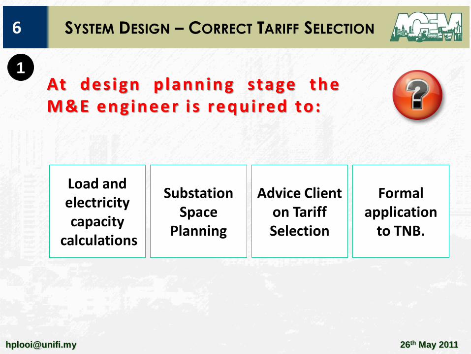
At des ign planning stage theM&E engineer i s required to:
26th May [email protected]
SYSTEM DESIGN – CORRECT TARIFF SELECTION6
Load and electricity capacity
calculations
Substation Space
Planning
Advice Client on Tariff Selection
Formal application
to TNB.
1

Voltage Leve l Se lect ion
26th May [email protected]
SYSTEM DESIGN – CORRECT TARIFF SELECTION8
MD ranges Supply
Voltage
Typical Supply Scheme
Up to 12kVA 230V Overhead service mains from LV mains
12kVA – 100kVA 400V 3 phase o/h or u/g LV existing service mains
100kVA – 1000kVA 400V Direct cable service from LV board in
substations (single or double chamber)
1000kVA –
5000kVA
11kV Directly fed thro’ TNB 11kV system (11kV
switch room
1000kVA –
10000kVA
22kV Directly fed thro’ TNB 11kV system (22kV
switch room)
500kVA –
25000kVA
33kV Directly fed thro’ TNB 11kV system (33kV
switch room
Above 25000kVA 132kV
275kV
Directly fed thro’ TNB 132/275kV system
(132/275kV switching stations)
1

26th May [email protected]
SYSTEM DESIGN – CORRECT TARIFF SELECTION9
Tariff Unit Rates
A (Domestic) sen/kWh 21.8 to 46 sen
B (LV Commercial)
Up to 200kWh
>200kWh
sen/kWh
sen/kWh
38.0
40.8
C1 (MV General Commercial)
MD consumption
kWh consumption
RM/kW
sen/kWh
24.6
29.6
C2 (MV peak/off peak Commercial)
MD consumption
kWh consumption (peak hours)
kWh consumption (off peak hours)
RM/kW
sen/kWh
sen/kWh
36.6
29.6
18.2
D (LV Industrial)
Up to 200kWh
>200kWh
sen/kWh
sen/kWh
34.2
36.6
1

26th May [email protected]
Tariff Unit Rates
E1 (MV General Industrial)
MD consumption
kWh consumption
RM/kW
sen/kWh
24.6
28.0
E2 (MV peak/off peak Industrial)
MD consumption
kWh consumption (peak hours)
kWh consumption (off peak hours)
RM/kW
sen/kWh
sen/kWh
30.8
29.6
18.2
E3 (HV peak/off peak Industrial)
MD consumption
kWh consumption (peak hours)
kWh consumption (off peak hours)
RM/kW
sen/kWh
sen/kWh
29.6
28.6
16.8
T h e s e l e c t i o n o f v o l ta g e c o n n e c t i o n a n d t a r i f fs e l e c t i o n h a v e s o m e r e l at i o n . H o we v e r at“bo rder l ine cases”, s o m e d e v i a t i o n s a r e a l l o w e d .
SYSTEM DESIGN – CORRECT TARIFF SELECTION10
1

S e l e c t i n g t a r i f f h a s c o m m e r c i a l c o n s e q u e n c e
26th May [email protected]
SYSTEM DESIGN – CORRECT TARIFF SELECTION11
LV ConnectionTariff B/D
LV or MV
connection
<1000kVA
1000kVA –1500kVA
>2000kVA
MV Connection
Tariff C/E
Pattern of
Consumption,
Load Profile
GeneralTariff C1/E1
peak/off peakTariff C2/E2
1

Cost differencebetween tariff E1(higher) & D (lower) at80% load diversity
Cost differencebetween tariff E1(higher) & D (lower) at60% load diversity
1

1Monthly chargedifference betweentariff E1 (higher) andE2 (lower) for 3 shifts
At only 2 shiftscharges under tariffE1 may be lowerthan tariff E2.

26th May [email protected]
C o m m o n f a i l u r e b y i n e x p e r i e n c e d p r a c t i t i o n e r ( i n c l u d i n g c o n t r a c t o r s w h o a d v i s e c l i e n t s ) ?
SYSTEM DESIGN – CORRECT TARIFF SELECTION14
1
N o s t u d y i s d o n e t o d e t e r m i n e t h e c o r r e c t t a r i f fs t r u c t u r e d u r i n g p l a n n i n g s t a g e .
T h e w r o n g t a r i f f s t r u c t u r e i n c a s e o f M D a r o u n d7 5 0 k VA t o 1 . 5 k VA i s p r o p o s e d .
T h e w r o n g t a r i f f s t r u c t u r e i n c a s e o f s e l e c t i o nb e t w e e n p e a k / o f f p e a k o r g e n e r a l t a r i f f s t r u c t u r ei s p r o p o s e d .

26th May [email protected]
C o m m o n f a i l u r e b y i n e x p e r i e n c e d p r a c t i t i o n e r s ( i n c l u d i n g c o n t r a c t o r s w h o a d v i s e d c l i e n t s ) ?
SYSTEM DESIGN – CORRECT TARIFF SELECTION15
1
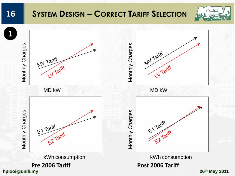
P r e 2 0 0 6 Tar iff Structure
At less than 1MVA LV tar iff is lower than MV tar iff.
For load >1MVA and load diversity >75% MV tar i ffstructure is cheaper. However a deta i l load analys isneed to be executed to determine the best tar i f fstructure.
They exis t a c l e a r d e l i n e a t i o n b e t w e e n C 2 / E 2( p e a k / o f f p e a k t a r i f f s ) a n d C 1 / E 1 ( g e n e r a l t a r i f f s )w h e n a t l e a s t 3 s h i f t s a r e r u n . H o w e v e r t h i s 3s h i f t s m u s t b e t r a n s l a t e d i n t o h i g h k W hc o n s u m p t i o n d u r i n g o f f - p e a k h o u r s . S t u d y n e e d t ob e d o n e t o a s c e r t a i n a t p l a n n i n g s t a g e .
26th May [email protected]
SYSTEM DESIGN – CORRECT TARIFF SELECTION16M
onth
lyC
harg
es
MD kW
Month
lyC
harg
es
MD kW
Pre 2006 Tariff Post 2006 Tariff
Month
lyC
harg
es
kWh consumption
Month
lyC
harg
es
kWh consumption
1

26th May [email protected]
Conc lus ion
1. A clear delineation between LV and MV tariff is presented in
the post 2006 tariff. The consultant if possible should opt for
LV tariff taking into consideration availability and capacity of
existing LV network and substations. Planners can also look
at the possibility of „connection at MV‟ but „metering at LV‟
since new rules are being drafted by TNB to force
connection at MV even at 500kVA.
2. The post 2006 tariff structure is much less supportive of
„peak/off peak‟ demand-management. This require a more
stringent analysis of load demand and the economics of
running 3-shifts.
3. Current TNB supply agreement specify that tariff opted must
stay for 5 years before changing tariff in agreement.
SYSTEM DESIGN – CORRECT TARIFF SELECTION17
1

26th May [email protected]
SELECTING GENERATOR CAPACITY19
G enerator s et s are mandatory in t he fo l lowing instances:
2
Law / By Law Conditions Standby Generator
1 UBBL Section
243
Fire Lift to be provided for
buildings where last occupied
floor is 18.5m above fire
appliance access level.
Standby generator
required as 2ndary
supply for fire lifts.
2 UBBL Sections
226, 231, 232,
244, 247 etc
and 10
Schedule
Sprinkler, Wet Riser,
Pressurised Hydrants, Hose
Reel system(s) to be provided
in accordance with occupancy
hazard class and built-up area
in accordance with Tenth
Schedule of UBBL.
Standby generator
only required if the
2ndary supply to
services pumps are
NOT diesel engine.

26th May [email protected]
SELECTING GENERATOR CAPACITY20
UB B L Tent h Schedule ;S e c o n d a r y s u p p l y f o r F i r e S e r v i c e s
2
T y p i c a l S c h e m e
S t a n d b y s e r v i c e sf o r f i r e p u m p i se l e c t r i c .
M a i n s s t a n d b yg e n e r a t o r p r o v i d e2 n d a r y s u p p l y t os t a n d b y e l e c t r i cp u m p .
M a i n s S t a n d b yG e n e r a t o r h a s t ob e s i z e d t o c a t e rf o r f i r e p u m ps t a r t i n g s u r g e

26th May [email protected]
SELECTING GENERATOR CAPACITY21
UB B L Tent h Schedule ;S e c o n d a r y s u p p l y f o r F i r e S e r v i c e s
2
A l t e r n a t i v e C a s e 1
S t a n d b y s e r v i c e sf o r f i r e p u m pd i e s e l e n g i n e .
M a i n s s t a n d b yg e n e r a t o r n o tr e q u i r e d i f U B B L2 4 3 d o n o t a p p l y .

26th May [email protected]
SELECTING GENERATOR CAPACITY22
UB B L Tent h Schedule ;S e c o n d a r y s u p p l y f o r F i r e S e r v i c e s
2
A l t e r n a t i v e C a s e 2
S t a n d b y s e r v i c e sf o r f i r e p u m p i sd i e s e l e n g i n e .
U B B L 2 4 3 ( f i r el i f t ) r e q u i r e sm a i n s s t a n d b yg e n e r a t o r.
M a i n s S t a n d b yG e n e r a t o r o n l yh a s t o b e s i z e d t oc a t e r f o r f i r e l i f ts t a r t i n g s u r g e

26th May [email protected]
SELECTING GENERATOR CAPACITY23
2 M a i n s S t a n d b y g e n e r a t o r n e e d t o
c a t e r f o r f i r e p u m p ( 5 0 H P )s t a r t i n g s u r g e .
M a i n s e s s e n t i a l s u p p l y s t e a d yl o a d 2 0 0 k W.
S t a n d b y G e n e r a t o r : 5 0 0 - 6 0 0 k V Ar e q u i r e d ,
O n l y 1 p u m p t o m a i n t a i n .
M a i n s S t a n d b y g e n e r a t o r n e e d t oo n l y t o c a t e r f o r f i r e l i f t s t a r t i n gs u r g e .
C a p a c i t y o f s t a n d b y g e n e r a t o r :2 5 0 k V A .
S e p a r a t e 5 0 H P d i e s e l e n g i n e f o rf i r e p u m p .
2 p u m p s t o m a i n t a i n .

26th May [email protected]
SELECTING GENERATOR CAPACITY24
2 G e n e r a t o r n o t s i z e d t o t a k e i n t o a c c o u n t
s t a r t i n g s u r g e o f l a r g e s t m o t o r i n s y s t e m .
G e n e r a to r S e l e c t i o n ; C o m m o n Fa i l u r e s
G e n e r a t o r n o t s i z e d t o t a k e i n t oa c c o u n t s t a r t i n g s u r g e o f l a r g e s tm o t o r i n s y s t e m .
Generator size = 150kVA
Generator size = 250kVA
G e n e r a t o r w i l l s t a l l o n l i f ts t a r t i n g !
C o r r e c t s i z i n g o f G e n e r a t o r t o t a k ei n t o a c c o u n t l i f t s t a r t i n g s u r g e( a s s u m e 4 x r a t e d ) .

26th May [email protected]
SELECTING GENERATOR CAPACITY25
2 G e n e r a t o r n o t s i z e d t o t a k e i n t o a c c o u n t
s t a r t i n g s u r g e o f l a r g e s t m o t o r i n s y s t e m .
G e n e r a to r S e l e c t i o n ; C o m m o n Fa i l u r e s
G e n e r a t o r n o t s i z e d t o t a k e i n t oa c c o u n t s t a r t i n g s u r g e o f l a r g e s tm o t o r i n s y s t e m .
A s s u m e e s s e n t i a l s t e a d y l o a d= 1 5 0 k V A
F i r e p u m p = 7 5 H P & s t a r t i n g s u r g e5 . 5 x r a t e d
Generator size = 250kVA
G e n e r a t o r w i l l s t a l l o n F i r eP u m p s t a r t i n g !
Generator size = 420kVA (min size)
C o r r e c t s i z i n g o f G e n e r a t o rt o t a k e i n t o a c c o u n t l i f ts t a r t i n g s u r g e .

26th May [email protected]
SELECTING GENERATOR CAPACITY26
2 Best Pract i ce
L a r g e I n s t a l l a t i o n w h e r e s t a n d b y g e n e r a t o r i sr e q u i r e d u n d e r U B B L 2 4 3 . U s e s e p a r a t e d i e s e le n g i n e f o r s t a n d b y f i r e p u m p .
I n a l l c a s e s i z e g e n e r a t o r t o c a t e r f o r s t a r t i n gs u r g e o f l a r g e s t m o t o r :
G e n e r a t o r C a p a c i t y =
( S t e a d y s t a t e o f E s s e n t i a l L o a d ) – ( L e s s l a r g e s tm o t o r ) + ( S t a r t i n g s u r g e o f l a r g e s t m o t o r )

26th May [email protected]
WIRING DESIGN – EARTHING SYSTEM28
M a ny E l e c t r i c a l E n g i n e e r s a r e st i l lc o n f u s e d o n s p e c i f y i n g t y p e o f e a r t h i n gsy s t e m
W h a t a r e t h e t y p e s o f e a r t h i n g s y s t e m s u s e d i n M a l a y s i aw h i c h a r e i n a c c o r d a n c e w i t h M S , I E C o r B S w i r i n gs t a n d a r d s ?
3
EARTHING FOR POWER DISTRIBUTION
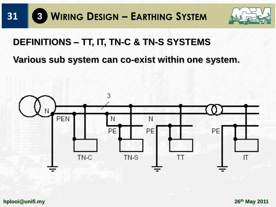
DEFINITIONS – TT, IT, TN-C & TN-S SYSTEMS

WIRING DESIGN – EARTHING SYSTEM29
26th May [email protected]
MS/IEC60364 earthing – 2 letters:
(a) 1st letter Transformer neutral:
(i) “T” for connected
(ii) “I” for isolated
(b) 2nd letter; Frame earth:
(i) “T” for directly connected to
earth
(ii) “N” for connected to the
neutral at the origin of
installation.
EARTHING FOR POWER DISTRIBUTION
DEFINITIONS – TT, IT, TN-C & TN-S SYSTEMS
British IEE or BS7671 has the same definitions.
3

WIRING DESIGN – EARTHING SYSTEM30
26th May [email protected]
3
DEFINITIONS – TN-C, TN-S, TN-CS SYSTEMS
The TN System can also
be sub divided into sub
system by the addition
of a 3rd letter:
TN-C; N & PE are
common (PEN)
TN-S;
N & PE are separate
TN-C-S;
TN-C occurs up -stream
& TN-S downstream
WIRING DESIGN – EARTHING SYSTEM31
26th May [email protected]
3
DEFINITIONS – TT, IT, TN-C & TN-S SYSTEMS
Various sub system can co-exist within one system.
WIRING DESIGN – EARTHING SYSTEM32
26th May [email protected]
3
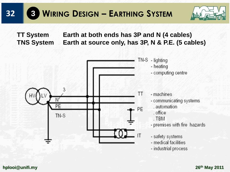
TT System Earth at both ends has 3P and N (4 cables)
TNS System Earth at source only, has 3P, N & P.E. (5 cables)

WIRING DESIGN – EARTHING SYSTEM34
26th May [email protected]
3
Malaysia
UK (parts)TN-C system in public distribution
TT system in public distribution
26th May [email protected]
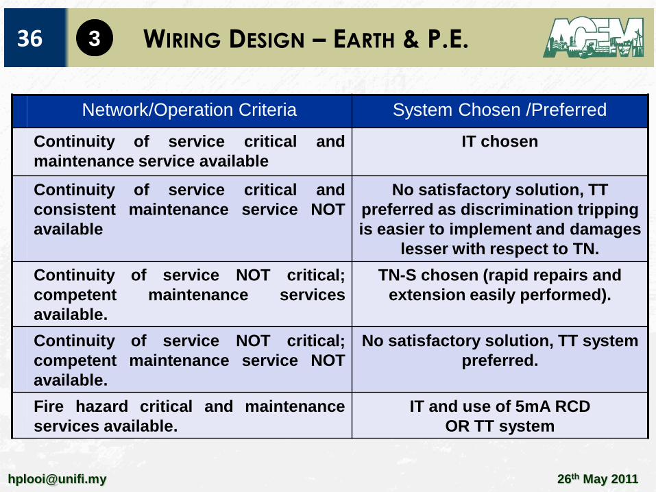
WIRING DESIGN – EARTH & P.E.36 3
Network/Operation Criteria System Chosen /Preferred
Continuity of service critical and
maintenance service available
IT chosen
Continuity of service critical and
consistent maintenance service NOT
available
No satisfactory solution, TT
preferred as discrimination tripping
is easier to implement and damages
lesser with respect to TN.
Continuity of service NOT critical;
competent maintenance services
available.
TN-S chosen (rapid repairs and
extension easily performed).
Continuity of service NOT critical;
competent maintenance service NOT
available.
No satisfactory solution, TT system
preferred.
Fire hazard critical and maintenance
services available.
IT and use of 5mA RCD
OR TT system

26th May [email protected]
WIRING DESIGN – EARTH & P.E.37 3
Network/Operation Criteria System Chosen /Preferred
Special features; very long networks TT preferred
Special features; Standby Power Supply TT preferred
Special features; Load sensitive to high
load currents (e.g. motors)
TT preferred OR
IT can be acceptable
Special features; Low natural insulation
(furnace) OR very large HF filters
(computers).
TN-S preferred.
Special features; control and monitoring
systems
IT for continuity of service OR
TT for enhanced equipotentiality
26th May [email protected]
WIRING DESIGN – EARTH & P.E.38
C o m m o n Fa i l u r e s
N o c l e a r u n d e r s t a n d i n g o f E a r t h i n g s y s t e m
I n c a m p u s t y p e e n v i r o n m e n t , T T s y s t e m b e t w e e ns w i t c h b o a r d s a r e u s e d ( o n l y 4 c a b l e s a n d w i t h o u t P E )h o w e v e r p r o p e r e a r t h i n g a t b o t h e n d s a r e n o ti n s t a l l e d .
W r o n g e a r t h i n g s y s t e m s e l e c t e d , e . g . m o s t e n g i n e e r sa r e N O T f a m i l i a r w i t h “ I T ” s y s t e m ( u n e a r t h e dn e u t r a l ) . H o w e v e r I T s y s t e m s h o u l d b e u s e d i n c r i t i c a ls e r v i c e s s u c h a s o p e r a t i n g t h e a t r e . C u r r e n t i n i t i a t i v e sa r e b e i n g u n d e r t a k e n t o d r a f t s t a n d a r d s a n d p r o m o t eu s e o f I T s y s t e m f o r c r i t i c a l s e r v i c e i n M a l a y s i a .
3

26th May [email protected]
WIRING DESIGN – EARTH & P.E.40
M a n y E l e c t r i c a l E n g i n e e r s a r e s t i l l c o n f u s e d o ns p e c i f y i n g t y p e o f e a r t h i n g s y s t e m a n d t h ea s s o c i a t e d p r o t e c t i v e e a r t h c o n d u c t o r s .
Ty p i c a l s p e c i f i c a t i o n s :
W i r i n g t o c o m p l y w i t h I E E w i r i n g r e g u l a t i o n s…
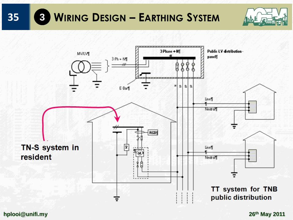
Ty p i c a l d e s c r i p t i o n i n p r i c e d e s c r i p t i o n
1 . L i g h t i n g w i r i n g u s i n g 2 x 1 . 5 m m ² - 1 C + E2 . S u b m a i n s w i r i n g u s i n g 4 x 5 0 m m ² - 1 C + E
4
W h a t i s t h i s “+ E” ?
TT System Earth at both ends has 3P and N (4 cables)
TNS System Earth at source only, has 3P, N & P.E. (5 cables)

26th May [email protected]
WIRING DESIGN – EARTH & P.E.41
B e f o r e 2 0 0 0
“ Ea r t h c on t i n u i t y ” c a b l e s a r e t y p i c a l l y :
C o p p e r t a p e
C a b l e a r m o u r i n g
Ev e n c o n t i n u i t y o f c a b l e t r u n k i n g / t r a y s .
A f t e r 2 0 0 0
T h i s i s N O TA C C E P TA B L E .
C a b l i n g s y s t e mw i l l b e d e e m e dn o t i n c o m p l i a n c ew i t h M S , I E C a n dI E E w i r i n g c o d e s .
4

26th May [email protected]
What is a l lowable as P.E .?
WIRING DESIGN – EARTH & P.E.42
Types of P.E. approved
Conductors in multi core cables
Insulated or bare conductors in a common enclosure with liveconductors
Fixed installed bare or insulated conductors
Metallic cables sheath, cable screen, cable armour, wirebraid,concentric conductors, metallic conduit subject to compliancewith 543.2.2.
In China, Italy, UK etc cable trays and ladders can be used as P.E.
Types of P.E. not approved [543.2.3]
Water pipes
Support wire …others
4

26th May [email protected]
WIRING DESIGN – EARTH & P.E.43 4
Cross sectional
areas of line
conductors
S
(mm²)
Minimum cross sectional area of the corresponding
protective conductor (mm²)
If the protective conductor
is of the same material as
the line conductor
If the protective conductor is
not of the same material as
the line conductor
S < 16 S K1/K2 x S
16 < S < 35 16 a K1/K2 x 16
S > 35 S/2 a K1/K2 x S/2
Where
K1 is the value of k for the line conductor, selected from table A54.1 or from the tables of
IEC50364-4-43 according to the resistance of the conductor and insulation.
K2 is the value of k for the conductor selected from tables A 54.2 to A54.6 as applicable
a for a PEN conductor the reduction of the cross section area is permitted only in
accordance with the rules for sizing of the neutral conductor (see IEC 60364-5-52).
EARTHING ARRANGEMENT PART 5-54

WIRING DESIGN – EARTH & P.E.44
26th May [email protected]
EARTHING ARRANGEMENT PART 5-54
Generally P.E. must be half size phase conductor.
Circuit with phases <16mm² must have P.E. SAME size as phase
condutor.
If cable armouring and cable trays/trunking (steel) are to be
used as P.E., then:
1. Above 2 rules must be complied; and
2. Effective area of P.E. (different from copper) must be
corrected with K1 and K2 factors which will require larger
cross sectional area of P.E. for steel.
4

26th May [email protected]
WIRING DESIGN – EARTH & P.E.45 4
S p e c i f y S u b M a i n s :
1 . S u b M a i n s w i r i n g u s i n g 4 x 5 0 m m ² - 1 C + 1 x 2 5 m m ² - 1 C
2 . S u b m a i n s w i r i n g u s i n g 5 x 1 6 m m ² - 1 C
F i n a l s u b c i r c u i t :
1 . L i g h t i n g w i r i n g3 x 1 . 5 m m ² - 1 C
2 . F i n a l s u b c i r c u i tw i r i n g 5 x 1 0 m m ² - 1 C
COMPLY WITH MS, IEC AND BS WIRING CODES

26th May [email protected]
WIRING DESIGN – MAINS CABLE SIZING47
5 TYPICAL CABLING SIZING FOR COST OPTIMISATION
Transformer Neutral Earth
MSB Main Earth Bar
Main Cables;1200A = 7x300mm² XLPE/PVC1600A = 11x400mm² XLPE/PVC2000A = 14x400mm² XLPE/PVC2000A = 7x630mm² XLPE/PVC3000A = 14x630mm² XLPE/PVC
TT Earthing System
FAIL Cable Size

26th May [email protected]
WIRING DESIGN – MAINS CABLE SIZING48
5 COMPLIANCE WITH MS, IEC AND BS WIRING CODES.
Current Carrying capacities Annex A – a road map
Cable in air, ambient temp < 30degCCable in ground, ambient temp < 20degC
Temp correction factorTable A52.14 & A52.15
Soil thermal resistivity < 2.5 K-m/Wcorrection factor soil t-rTable A52.15
Groups of Cables types A to D in table 52.1 Table A52.2 to A52.7
Table A52.17 to A52.19Group reduction factor
Groups of Cables types E to F in table 52.1 Table A52.8 to A52.13
Table A52.20 to A52.21Group reduction factor
Groups in conduits, trays, ductingsF = 1/ SQRT(n)

5

26th May [email protected]
WIRING DESIGN – MAINS CABLE SIZING51
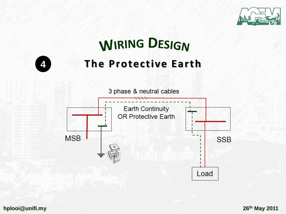
5 BASED ON TABLE B52.10 (CURRENT RATING) AND
TABLE B52.17 (GROUP REDUCTION FACTOR)
Rating Cable Size No of
cables per
phase
Rating of
individual cables
(trefoil) B52.10
Group
reduction
factor B52.17
Effective rating of
cable system
1200A 7x300mm² 2 561 Amps 0.88 987 – Fail
1200A 11x300mm² 3 561 Amps 0.82 1380A – Pass
1200A 7x400mm² 2 656 Amps 0.88 1154A – Fail
1600A 11x400mm² 3 656 Amps 0.82 1613A – Pass
1600A 14x300mm² 4 561 Amps 0.77 1727A – Pass
2000A 14x500mm² 4 749 Amps 0.77 2306A – Pass
3000A 14x500mm² 4 749 Amps 0.77 2306A – Fail
3000A 14x630mm² 4 905 Amps 0.77 2787A – Fail
3000A 18x630mm² 5 905 Amps 0.75 3393A – Pass
MethodF5 (Trefoil)

5
WIRING DESIGN – MAINS CABLE SIZING52
Rating Cable Size No of
cables per
phase
Rating of
individual cables
(flat) B52.10
Group
reduction
factor B52.17
Effective rating of
cable system
1200A 7x300mm² 2 629 Amps 0.88 1107 – Fail
1200A 11x300mm² 3 629 Amps 0.82 1547 – Pass
1200A 7x400mm² 2 754 Amps 0.88 1327A – Pass
1600A 11x400mm² 3 754 Amps 0.82 1854A – Pass
1600A 14x300mm² 4 629 Amps 0.77 1937A – Pass
2000A 14x500mm² 4 868 Amps 0.77 2673A – Pass
3000A 14x500mm² 4 868 Amps 0.77 2637A – Fail
3000A 14x630mm² 4 1005 Amps 0.77 3095A – Pass
BASED ON TABLE B52.10 (CURRENT RATING) AND
TABLE B52.17 (GROUP REDUCTION FACTOR)
Method F4 (Flat)

26th May [email protected]
A f t e r C a b l e S i z i n g e n s u r e t h a t t h e s e l e c t e dm e t h o d o f i n s t a l l a t i o n i s a d h e r e d a s c u r r e n tr a t i n g d e p e n d s o n i n s t a l l a t i o n m e t h o d .
WIRING DESIGN – MAINS CABLE SIZING53
5
Rating Cable Size Cables
/phase
Individual cables
(trefoil) B52.10
Group reduction
B52.17
Effective rating of
cable system
3000A 18x630mm² 5 905 Amps 0.75 3393A – Pass
Rating Cable Size Cables
/phase
Individual cables
(trefoil) B52.10
Group reduction
B52.17
Effective rating of
cable system
3000A 14x630mm² 4 1005 Amps 0.77 3095A – Pass
1 cable diameter distance
Neutral
Neutral

26th May [email protected]
C o m m o n p r o b l e m s w i t h M a i n s C a b l e S i z i n g
Cable not sized based on MS/IEC method. Usually groupreduction factor NOT applied.
After sizing cables, the cable rating is based oninstallation method (flat or trefoil). Installation methodDO NOT follow recommended installation method atdesign. Cable heating occurs.
Best Practice
WIRING DESIGN – MAINS CABLE SIZING54
5
1. Never run cables >1200A more than 100m
2. Ensure installation method match designed method.
3. Using many cables per phase has diminishing returns.
Use bus ducts for >1200A.

25 Common Problems
for M&E Engineers
Armada Hotel , Petaling Jaya
26th May 2011
Ir. Looi Hip Peu | [email protected]