Embed Size (px)
Citation preview

SANDIA REPORT SAND2008-2338 Unlimited Release Printed May 2008
Common Tester Platform Concept Michael J. Hurst Prepared by Sandia National Laboratories Albuquerque, New Mexico, and Livermore, California 94550 Sandia is a multiprogram laboratory operated by Sandia Corporation, a Lockheed Martin Company, for the United States Department of Energy National Nuclear Security Administration under Contract DE-AC04-94AL85000.

ii
Issued by Sandia National Laboratories, operated for the United States Department of Energy by Sandia Corporation.
NOTICE: This report was prepared as an account of work sponsored by an agency of the United States Government. Neither the United States Government, nor any agency thereof, nor any of their employees, nor any of their contractors, subcontractors, or their employees, make any warranty, express or implied, or assume any legal liability or responsibility for the accuracy, completeness, or usefulness of any information, apparatus, product, or process disclosed, or represent that its use would not infringe privately owned rights. Reference herein to any specific commercial product, process, or service by trade name, trademark, manufacturer, or otherwise, does not necessarily constitute or imply its endorsement, recommendation, or favoring by the United States Government, any agency thereof, or any of their contractors or subcontractors. The views and opinions expressed herein do not necessarily state or reflect those of the United States Government, any agency thereof, or any of their contractors.
Printed in the United States of America. This report has been reproduced directly from the best available copy.
Available to DOE and DOE contractors from
U.S. Department of Energy
Office of Scientific and Technical Information
P.O. Box 62
Oak Ridge, TN 37831
Telephone: (865)576-8401
Facsimile: (865)576-5728
E-Mail: [email protected]
Online ordering: http://www.osti.gov/bridge
Available to the public from
U.S. Department of Commerce
National Technical Information Service
5285 Port Royal Rd
Springfield, VA 22161
Telephone: (800)553-6847
Facsimile: (703)605-6900
E-Mail: [email protected]
Online order: http://www.ntis.gov/help/ordermethods.asp?loc=7-4-0#online

iii
SAND2008-2338
Unlimited Release
Printed May 2008
Common Tester Platform Concept
Michael J. Hurst, Radar Fuzes Department
Sandia National Laboratories
P.O. Box 5800
Albuquerque, New Mexico 87185-0348
ABSTRACT
This report summarizes the results of a case study on the doctrine of a common tester platform, a concept of a standardized platform that can be applicable across the broad spectrum of testing requirements throughout the various stages of a weapons program, as well as across the various weapons programs.
The common tester concept strives to define an affordable, next-generation design that will meet testing requirements with the flexibility to grow and expand; supporting the initial development stages of a weapons program through to the final production and surveillance stages. This report discusses a concept investing key leveraging technologies and operational concepts combined with prototype tester-development experiences and practical lessons learned gleaned from past weapons programs.

iv
Acknowledgments The development of the ideas and concepts used in the design of common tester architecture involved a large number of people who contributed in many ways.
Since many design concepts discussed in this report are borrowed from WR projects, we are grateful to Gerald Boyd, of the Weapon Controllers Department, 5351, who was instrumental in the original development of a previous tester system.
The contribution of several Sandia experts in the design of developmental testers was also very valuable. These experts include Jesse Lai, Brian DuVerneay, Christopher Rodenbeck, and Jeffrey Pankonin, of the Radar Fuzing Department, 5353.
The technical contributions of Edward Bernal of the Radar Fuzing Department, 5353, were immensely valuable to the performance scoping, development, and definition of the common tester platform.
The management support of Tedd Rohwer, Manager of the Radar Fuzing Department, 5353, and Perry Molley, Manager of the Weapons Controllers Department, 5351, made this research possible by helping to formulate this case study and working to ensure sponsorship for this research.
The programmatic support of John Dye, of the Weapons Controllers Department, 5351, and George Laguna, of the Radar Fuzing Department, 5353, was instrumental in opening the doors in the weapons community necessary to gain access to programmatic support to develop this concept. This project would not have been a success without their efforts.
Finally, Doug Mangum, Manager of the B61 System Engineering Department, 2111, contributed immensely to making this report possible. Specifically, Doug was responsible for the overall strategy of standardization of testing; this helped ensure the definition of surveillance test capabilities discussed in this report for the surveillance testers. Doug also made available the funding support that made this study possible.
This research has been advanced and improved thanks to the efforts of many individuals at National Instruments and specifically, Jamie Olive, Ed McConnell, and David Bonal, who have been invaluable in the effort to leverage and develop a new approach to tester development in the weapons community based on industrial practices.
In addition, gratitude is expressed to Phillip Brittenham, of the Creative Arts Department, 3654, for his careful review of this report, John Leon, of the Radar Fuzing Department, 5353, for his assistance in the preparation of this manuscript, and Chris Brigman, of the Creative Arts Department, 3654, for his talented graphics designs.

v
Contents
EXECTIVE SUMMARY..................................................................................................IX
1. BACKGROUND AND OVERVIEW......................................................................... 1
1.1. Programmatic Testing Categories ............................................................. 1
1.1.1. Developmental Evaluation Testing ............................................................ 1
1.1.2. Quality/Reliability Testing........................................................................... 2
1.1.3. Qualification Testing .................................................................................. 2
1.1.4. Production Testing..................................................................................... 2
1.1.5. Surveillance Testing .................................................................................. 3
1.2. Serial vs. Parallel Tester Development a New Paradigm........................... 4
1.3. Rationale for Paradigm Shift ...................................................................... 6
1.4. Tester Platforms – Analysis of Past Tester Architectures .......................... 8
1.4.1. Rack and Stack Instrumentation Manually Operated................................. 9
1.4.2. Packaged Rack-and-Stack Instrumentation + Custom Operating Program .................................................................................. 10
1.4.3. Custom-Hybrid Design with Fabricated Custom-Made, Custom-Built, Hardware ................................................................................................. 12
2. CTP – DESIGN INTENT AND CHARACTERISTICS............................................ 15
2.1. Introduction .............................................................................................. 15
2.2. CTP – Functional Overview ..................................................................... 18
2.3. CTP – Architecture .................................................................................. 21
2.3.1. System Management Software................................................................ 22
2.3.2. Data Management System ...................................................................... 24
2.3.3. Application Development Software (ADE) ............................................... 25
2.3.4. Measurement and Control Services......................................................... 25
2.3.5. Computing and Measurement Bus .......................................................... 26
2.4. CTP – Implementation ............................................................................. 28
2.4.1. Implementation Infrastructure .................................................................. 28
2.4.2. CTP Qualification..................................................................................... 28
2.4.3. Implementation Budget ............................................................................ 30
2.4.4. Implementation Plan ................................................................................ 30
3. CONCLUSION ...................................................................................................... 37
3.1. Caveats.................................................................................................... 37

vi
List of Figures Figure ES-1. Application of a Common Platform Overview ............................................ix
Figure ES-2. Shared Core Across Project Applications..................................................xi Figure 1. Development Testing Process ........................................................................ 1
Figure 2. Programmatic Testing Matrix: Six Levels of Design and Five Testing Categories ..................................................................................................... 3
Figure 3. Timeline of Design Maturation and Programmatic Tester Requirements ........ 4
Figure 4. Historical Tester Development Trends ............................................................ 5
Figure 5. Historical vs. Proposed Future Tester Development Efforts............................ 6
Figure 6. Application of a Common Platform Overview................................................ 19
Figure 7. CTP Structure Using a Core Foundation....................................................... 20
Figure 8. National Instruments TestStand Architecture ................................................ 24
Figure 9. Bandwidth Chart............................................................................................ 27
Figure 10. AFS Development Phased Approach to Tester Design .............................. 31
Figure 11. Die Level Tester Schematic ........................................................................ 32
Figure 12. Radar and Tester Development Timeline.................................................... 35
List of Tables Table 1. Typical DUT Testing Operations .................................................................... 17
Table 2. Tx Measurement Matrix.................................................................................. 33
Table 3. Rx Measurement Matrix ................................................................................. 34

vii
Acronyms and Abbreviations ADE application development environment AF&F arming, fuzing, and firing AFS arming, fuzing subsystem API application programming interface ASIC application specific integrated circuit COTS commercial off-the-shelf CTP common tester platform DA Design Agency DC direct current DMM digital multimeter DOE Department of Energy DUT device under test HALT highly accelerated life testing HASS highly accelerated stress screen IO input/output IVI Interchangeable Virtual Instruments KCP Kansas City Plant MB megabyte MCM multi-chip-module NI National Instruments NNSA National Nuclear Security Administration NWC nuclear weapons complex PA Production Agency PC personal computer PRT Product Realization Team PXI PCI extensions for instrumentation QAP quality assurance plan R&D research and development RADAR radio detection and ranging RB re-entry body RF radio frequency Rx receive or receiver sec. second(s) SFP soft front panel SNL Sandia National Laboratories SRS Software Requirements Specification Tx transmit or transmitter vs. verses WETL Weapons Evaluation Test Laboratory WQAP written quality assurance plan WR war reserve

viii
ix
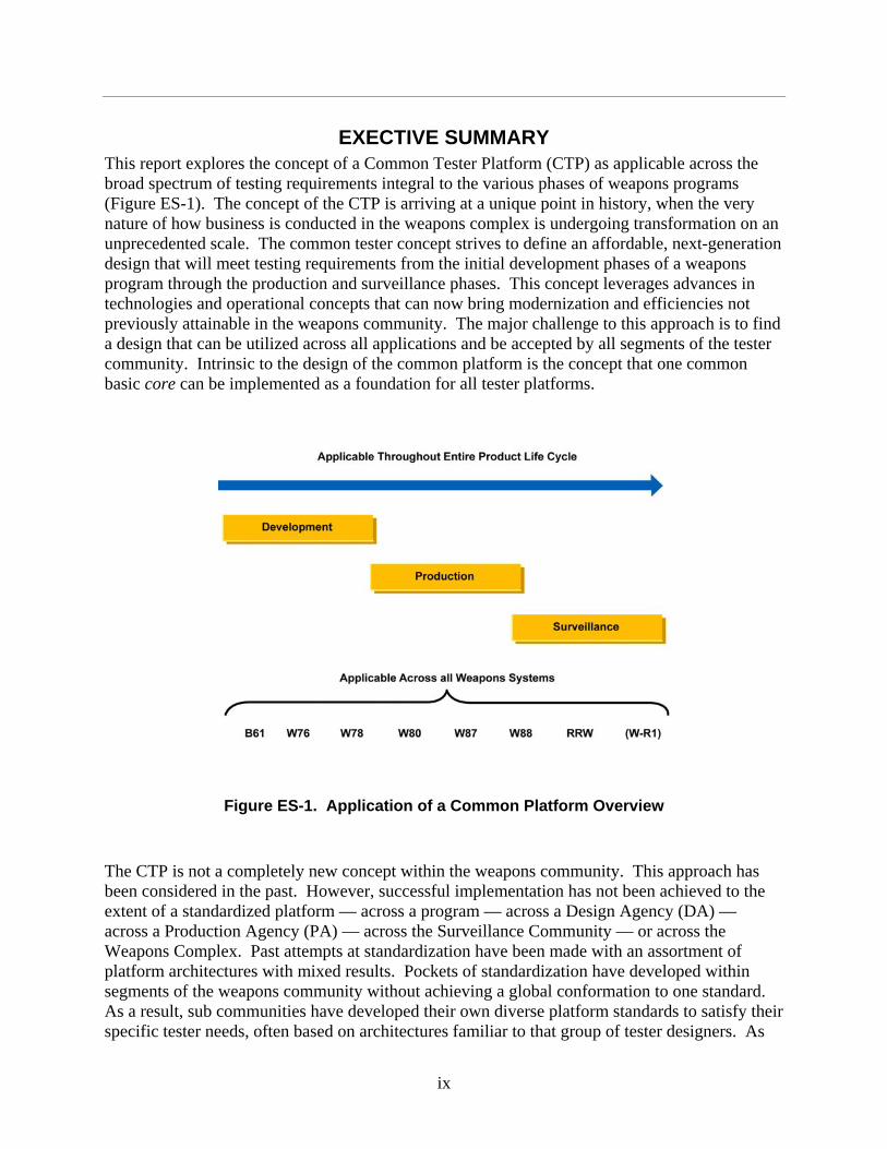
EXECTIVE SUMMARY This report explores the concept of a Common Tester Platform (CTP) as applicable across the broad spectrum of testing requirements integral to the various phases of weapons programs (Figure ES-1). The concept of the CTP is arriving at a unique point in history, when the very nature of how business is conducted in the weapons complex is undergoing transformation on an unprecedented scale. The common tester concept strives to define an affordable, next-generation design that will meet testing requirements from the initial development phases of a weapons program through the production and surveillance phases. This concept leverages advances in technologies and operational concepts that can now bring modernization and efficiencies not previously attainable in the weapons community. The major challenge to this approach is to find a design that can be utilized across all applications and be accepted by all segments of the tester community. Intrinsic to the design of the common platform is the concept that one common basic core can be implemented as a foundation for all tester platforms.
Figure ES-1. Application of a Common Platform Overview
The CTP is not a completely new concept within the weapons community. This approach has been considered in the past. However, successful implementation has not been achieved to the extent of a standardized platform — across a program — across a Design Agency (DA) — across a Production Agency (PA) — across the Surveillance Community — or across the Weapons Complex. Past attempts at standardization have been made with an assortment of platform architectures with mixed results. Pockets of standardization have developed within segments of the weapons community without achieving a global conformation to one standard. As a result, sub communities have developed their own diverse platform standards to satisfy their specific tester needs, often based on architectures familiar to that group of tester designers. As

x
an example, a tester’s software might be based on the C++ programming language because the originator of the system is a C++ programmer. Another engineer working on a similar type of tester system may choose to develop his system using Visual Basic because of his familiarity with that programming language. For a common foundational core to be successful and provide value, it must be adaptable to support the wide variety of expertise in the tester development community.
The architecture identified in this study is designed to exploit advances in software and hardware. It utilizes a test management software system that allows for simplified user interfaces to be built, providing an environment for building, sequencing, and modifying tests across an infinite assortment of instrumentation. This new common tester platform architecture possesses endless expansion capabilities. The incorporation of calibration sequencing, real-time data display, and embedded data analysis-manipulation will be possible. Other features include automating the generation of high-quality reports, functional evaluation or pass-fail determination, an infinite variety of data collection possibilities, and immediate results.
The challenge of the CTP is to satisfy the performance needs across the spectrum of requirements. Issues relevant to the developmental stage of a project differ from the priorities in the production stage of the same project. This architecture takes into account the broad spectrum of needs and offers a design that meets all phase requirements while maintaining a goal of commonality of the core. The goal is to maintain a 70 percent to 90 percent commonality of the core across a weapons program.
Study Objective
The objective of this study is twofold: (1) to understand the extent of tester application requirements within the phases of a weapons program and across analogous weapons programs and (2) to determine the extent to which the tenets of the common tester platform hypothesis can meet these requirements while fulfilling the transformation strategic goals identified in the Complex 2030 initiative.
This report evaluates a change in the paradigm used to develop testers. First, we consider the categories of testing that currently exist within the weapons community. Then, we compare historical methods and architectures to a modular, adaptable approach, highlighting the many advantages and disadvantages of each architecture. Next, a discussion of the paradigm shift from serial to parallel tester development is presented as applied to the Complex 2030 Strategic Goals. Finally, a description of the CTP outlines the functionality and architecture, presenting a comprehensive plan for implementation.
This document discusses the viability of the common tester platform concept. The intent of this report is not to define the project details of implementation but rather discuss the concept for management’s review. Project implementation details are discussed in subsequent reports outlining the path forward, project plan, schedule, and funding requirements based on the initial lessons learned during developmental builds and evaluation of this design approach.

xi
Study Scope and Context
As a case study of typical tester performance criteria, the tester requirements for a sophisticated subsystem — the MC4701 arming and fuzing subsystem (AFS) will be critiqued and reviewed in this report. This subsystem was chosen because of the familiarity of the system to the author and the amount of prototype tester development that has already been performed for this subsystem.
This list summarizes the Complex 2030 Strategic Goals that will be the standard on which this CTP will be assessed.
• Future programs would be operated in a more cost effective manner. • Capabilities would be consolidated and unnecessary duplication eliminated, yielding a
smaller infrastructure that is fully capable and sufficiently flexible. • Work would be optimized to maintain a responsive infrastructure. • Ease of production, maintenance, serviceability would be realized. • Reduce investment in legacy systems, outdated equipment, obsolete technology, and
spare parts retention.
Findings
The essence of the common tester hypothesis postulates that a common tester platform would increase affordability and flexibility. To achieve this, a standardized hardware/software platform can be adopted as an integrated core across complex partners and facilities. At the heart of the common tester concept is the notion of reuse. Standardized core software would afford savings by reusing the development investment made in the original core deployment with repeated reapplications in further deployments (Figure ES-2).
Figure ES-2. Shared Core across Project Applications
xii
In addition to the cost savings that accompany core software reuse, other advantages present themselves, such as leveraging technological advances in the commercial marketplace, increasing overall productivity, and reducing maintenance and operational costs.
Recent technological advancements in the area of automated testing and reporting in commercial-off-the-shelf (COTS) products are providing test engineers with a solid set of tools maintained and improved by the commercial marketplace. Requirements tracking, in-line data processing, automated instrument control, and enhancements in data connectivity, processing, and reporting are among some of the features currently available. These new technologies ultimately contribute to reduced labor requirements with the application of automation to traditionally manual activities. By relying on the commercial marketplace to drive these technologies, weapons programs can lower overall operational costs dramatically by standardizing on commercially available hardware and software instead of customization to meet testing needs.
Standardization of testing platforms among the various weapons elements would also lend itself to standardization of testing technique, including data formats and test sequences. With standardization among the agencies, scripted tests developed at one organization could be shared and reapplied at collaborating agencies, further maximizing the work performed at the different agencies.
A cornerstone to the common tester concept is the realization of increased productivity with the early investment in tester activation and early incorporation of the CTP into the initial develop-mental testing activities. Design engineers who are developing the underlying components of weapons assemblies may reap the greatest reward by bringing automation into their task. Traditionally, component testing has been done manually and is very costly in resources, time, and materials.
An additional advantage of a standardized platform will be the reduction in maintainability and operational costs and a reduction of spare parts inventory having to support only one version of tester as compared to dozens of different versions.
This study found that a COTS platform utilizing National Instruments TestStand software as the test management environment could meet the transformational goals of tester standardization analyzed in this report.

xiii
Caveats
Some important caveats should be kept in mind that applies to successful implementation of a CTP. First, this study considers one particular subsystem application — AFS testing requirements. Because of time and resource constraints, an exhaustive search for all tester requirements throughout the entire weapons complex was not done but instead the AFS was used as a representative case study. Second, there are programmatic factors outside of the realm of the CTP that will affect its implementation success such as:
• Successful collaboration and information sharing between the various stakeholders within the segments of the agencies in the tester community.
• A willingness among the stakeholders to embrace change, which may include retraining engineering staff to be able to use the new platform.
• A pooling of resources — to include funding — to support the implementation of the platform during the initial development stage.
These provisos, if not managed properly, will place in jeopardy the success of a common platform — dooming the concept to a limited success, with the project not realizing the full benefit of this concept.

xiv

1
1. BACKGROUND AND OVERVIEW To understand the issue of testers related to a weapons program, we must first develop an understanding of programmatic testing requirements relevant to the phases of a weapons program. Examination and evaluation testing — where testers are applied as tools — support the development, certification, production, and surveillance phases of a program. Several different factors need consideration in the tester discussion.
1.1. Programmatic Testing Categories The general topic of “testing” can be divided into five subcategories related to the maturation timeline of a weapons program. The testing subcategories, tester requirements for each subcategory, and the historical methods utilized to meet these requirements are discussed in the following sections.
1.1.1. Developmental Evaluation Testing
There is an initial stage of exploratory testing that supports evaluation and investigation of prototype design performance during the beginning stages of a project. This type of testing is intended to reveal design comprehensiveness, thoroughness, and technical merit. These tests are conducted from the discrete component level, to the subsystem level, through to the system level. Results are fed back into the design to implement changes for maturation of the product under development. Traditionally, the development of a product has been a cycle of design, prototype, test, evaluate results, adjust design, and then repeat the process until the design is finalized (Figure 1). Testing and evaluation of the results are significant activities during this developmental process.
Figure 1. Development Testing Process
This type of testing supports the first step in product development and is conducted at the DA. Historically, this type of “open bench-top” testing has been conducted with a mixture of rack and stack instrumentation, custom designed cards, and/or specialty equipment, semi-manually

2
executed because of the myriad and complexity of the measurements. In many cases, significant effort is required by designers to create firmware and software control of the instrumentation.
1.1.2. Quality/Reliability Testing
This category of testing is conducted primarily at the subsystem level, on mature designs, to gather quality-related performance information about the subsystem with respect to the realistic environmental conditions in which it is intended to operate. This category includes lifetime and stress testing (e.g., highly accelerated life testing [HALT]) with the purpose of uncovering design defects and weaknesses. Historically, this type of testing has been conducted with a mixture of rack and stack equipment along with prototype custom-built tester-emulators tailored to replicate the functionality of the next-level system. An example is to mimic the interface functionalities of the arming fuzing and firing (AF&F) system to the AFS. These emulators imitate the functional stimuli for the subsystem and can be costly to build and maintain. Traditionally, the data and measurements taken during these tests have been collected with limited automation. Additionally, some custom-designed cards and/or specialty equipment may be used during this phase. These types of tests are usually conducted at environmental test facilities that introduce variables such as temperature, vibration, hostile shock, or radiation while functioning the subsystem. During this stage of testing, margin testing would be conducted as a validation that design margin requirements have been met. Conducted mainly at the DA, test results are fed back into the design to implement needed improvements with a goal of developing a highly reliable product.
1.1.3. Qualification Testing
Another category of testing used for design evaluation is qualification testing. This type of testing is done to confirm that the final design meets the performance specifications using simulated environments that mimic the survivability extremes derived from the performance requirements documents. Test results are typically limited to a pass or fail determination collected on final production samples as an evaluation of the design and production processes. These pass/fail determinations have used a variety of software products for data analysis. During this type of testing, DA engineers use various programming languages (such as MATLAB or LabVIEW) or commercial software (such as DIAdem) to create specialty scripts for post-testing data evaluation. Developed software scripts do not undergo formal qualification reviews and are used primarily in limited applications for engineering evaluation of post-test data.
Qualification testing conditions can also include production testing (highly accelerated stress screen [HASS] and E-Tests), thermal cycling, logistics/flight, shock and vibration, hostile shock, and radiation. This category of testing is conducted at both the DA and the PA. Historically, testing has been conducted with a mixture of rack and stack equipment along with custom-built tester-emulators tailored to the evaluation needs of qualification, autonomous to the predecessor tester activities.
1.1.4. Production Testing
Prior to the final production phase of a project, development of production testers begins after performance criteria for the testers have been documented by the DA to the PA. Specialized equipment is designed by the PA and built to perform a collection of measurements that evaluate

3
the pass or fail performance of the manufactured part or subsystem. Evaluation is based on meeting the acceptance criteria established for the product. These testers are custom built and tailored to the evaluation needs of the production line for a particular part or subsystem to insure the acceptability of the produced product. In addition, production testing may utilize techniques that are nondestructive to the component or assembly under test such as HASS testing conducted on statistical samples from the production line. This type of testing takes place only at the PA. For this category of testing, the hardware and the software used undergo a formal qualification process.
1.1.5. Surveillance Testing
Once a weapon system is introduced into the stockpile, laboratory tests are conducted periodically on stockpile samples to evaluate the weapon’s nonnuclear systems to detect possible defects that may arise over the lifetime of the product because of handling, aging, manufacturing, or design. System and component testing, including functional testing, is used to identify defects or failures. The testers used to support this category of testing are custom built and tailored to the evaluation needs of the Weapons Evaluation Test Laboratory (WETL) located at Pantex, autonomous to the predecessor tester activities.
As illustrated in the Testing Matrix (Figure 2), the inter-relationships of the six levels of design and the five programmatic-testing categories for a typical war reserve (WR) project are summarized, identifying the organizations where that category of testing takes place.
Figure 2. Programmatic Testing Matrix: Six Levels of Design and Five Testing Categories

4
The five categories of testing follow a sequential timeline for a weapons project. Figure 3 illustrates these five categories relevant to a design maturation timeline, beginning at the component level, progressing through the programmatic mid-levels of subsystem and system, to the final stages of an operational system. The timeline illustrates the testing spin-off sub-activities identified in Figure 3 that are part of the project’s developmental phases. Although this timeline is based on an AFS project, the testing activities are typical for other subsystems in a weapon.
Figure 3. Timeline of Design Maturation and Programmatic Tester Requirements
1.2. Serial vs. Parallel Tester Development a New Paradigm Traditionally, for WR projects, initial developmental testing at the DA was supported using manually operated, rack and stack instrumentation. Then, at the midpoint of the project, testing requirements were defined as the design reached maturity. These requirements were captured in Product Specification (PS) documents. PA fabrication of testers was based on customized hardware-software platforms. Subsequently, resources were allocated for tester development at the later stages of the project, primarily to support the production and qualification testing needs. This serial approach to tester development (Figure 4), did not address testing requirements from the early stages of the project. This approach is rooted in the somewhat limiting train of thought

5
that automated, integrated testers cannot be developed or built until measurement requirements have been documented. Because of the non-standardized nature of past testers, legacy work could not be reused or leveraged for new project testing needs. This unnecessarily added significant development time and therefore cost for new testers. As programmatic requirements drive projects to shorten developmental cycles, this same paradigm cannot succeed.
Figure 4. Historical Tester Development Trends
A key to process improvement for tester development is to change this paradigm so that early programmatic testing requirements are met at time of need — concurrent with, or parallel to, need. In traditional tester engineering, a delay in tester development is a consequence of waiting until requirements are fully defined. A relatively long time can be spent defining the tester product, and a surprisingly long time is often spent developing the tester product. During past tester development projects, design engineers would work with the tester development engineer for several iterations to achieve the final desired result in tester operability.
Changing this business model would require that resources be applied at the beginning stages of the program, working alongside the design engineers to provide automated, integrated testers. This paradigm shift is illustrated in Figure 5. Initial testers would have to be adequately designed so that the platform could migrate or adapt as the product designs move from component level to surveillance, thus leveraging the foundational work performed in tester development.

6
Figure 5. Historical vs. Proposed Future Tester Development Efforts
The goal of this new paradigm is to introduce automated testing at the beginning stages of a project, identifying common measurement and testing needs that can be reapplied to future test categories. With a standardized platform established early in a project, the reutilization of the design would shorten the time required to achieve production and surveillance tester deployment. Redundant engineering costs would be eliminated, the primary cost driver being the effort to customize the test platform to the specific data and user interface needs of the agency performing the testing. Over time, development for these specific needs would be reduced once the benefits of reuse have been realized and implemented within the agency. Components to build testers would be based on the plug-and-play approach. A second shift in the business model is to utilize a flexible, adaptable, common platform based on COTS products, minimizing tester development, customization, and cost.
Developing a new tester platform capable of supporting all measurement and testing for future projects would require combining several separate operations into one system, allowing flexibility to changing operational requirements. The tester would support the developmental and characterization phases from the discrete component level through to the final system level (Figure 3).
1.3. Rationale for Paradigm Shift The drivers for change are summed up in several recently released reports. The Report on the Plan for Transformation of the National Nuclear Security Administration Nuclear Weapons Complex the Executive Summary begins with this statement, “Section 3111 of the John Warner National Defense Authorization Act for Fiscal Year 2007 (Public Law 109-364) directs the Secretary of Energy to develop a plan, in consultation with the Secretary of Defense and the

7
Nuclear Weapons Council, for transformation of the nuclear weapons complex to achieve a responsive infrastructure by 2030.”
In the Complex 2030 Report, the Executive Summary states the following:
National Nuclear Security Administration (NNSA) has developed a planning scenario that sets out our vision for the nuclear weapons complex of 2030. This scenario consists of four over-arching, long-term strategies:
(1) In partnership with the Department of Defense, transform the nuclear stockpile through development of Reliable Replacement Warheads, refurbishment of limited numbers of legacy designs, and accelerated dismantlement of the Cold War stockpile;
(2) Transform to a modernized, cost-effective nuclear weapons complex;
(3) Create a fully integrated and interdependent nuclear weapons complex; and,
(4) Drive the science and technology base essential for long-term national security.”
Key statements in these documents identify transformation goals to enhance responsiveness of design, certification, and production to include:
• Less costly and effective risk management.
• Timely support of design implementation.
• Design, develop, certify, and complete first production units with a frequency that both sustains the stockpile and exercises the supporting infrastructure and critical needs.
• Improved compatibility to design, develop, certify, and complete production of new or adapted warheads.
• An overall goal of an economically sustainable nuclear weapons enterprise.
Historically, testers for the nuclear weapons complex (NWC) have been developed to a set of specifications that typically are not available until after the design/development cycle for a given component is complete. Once the specifications are available, it can take years before the tester is completed. Further, as product complexity increases, it becomes exponentially more expensive both in dollars and in time to detect flaws later in the design cycle. With the mandate for change, today’s needs require that future testers be flexible enough to meet the engineer’s needs during design and then extend those capabilities into production testing and supply chain management. Some of the pressures faced by engineers today are as follows:
• Device complexity — one of the most visible trends is increased device complexity. Today’s devices combine multiple disparate technologies into a single functional unit. As a result, test system design must be flexible enough to support the wide variety of tests between components but also scalable to accommodate a larger number of test points as new measurement functionality is required.

8
• Shortened Development cycles — an example of this is the current Radio Frequency Integrated Circuit (RFIC) project, which has a timeline of 4 years, approximately half of the traditional 8 to 9 years. To be successful, engineering teams need to develop new test strategies to decrease test time and improve efficiencies from design through production and into supply chain management.
• Decreasing budgets — testing is becoming more expensive and time consuming. Engineers and designers must develop test strategies that reduce cost by increasing the throughput of their test systems, reducing the maintenance and upgrade costs, lowering the required capital investment, and reducing the overall no-recurring expense (NRE). The percentage of the programmatic budgets allocated to testing is also decreasing, requiring a need to achieve higher efficiency in testing expenditures.
• Quality Policy (QC-1) directives as set forth by Department of Energy (DOE)/NNSA — This directive includes continuous improvement processes (3.1.1), prevention vs. detection (3.1.2), design process (3.3.2), design verification (3.3.3), inspection, test, and acceptance (3.9), nonconformance (3.12), and software quality assurance (3.16). All of these directives apply to tester development.
• Tactical Business Practice Product Realization Process as set forth by DOE/NNSA — these regulatory documents include cost, schedule, and performance metrologies for a project. Changes to a product have greater cost and schedule impact as product realization proceeds towards the delivery and support steps. Effective use of concurrent engineering both in design and testers reduces changes in the later steps.
• Concurrent Qualification — Application of concurrent engineering to product will require that concurrent qualification principles be applied to tester development during future testing activities to improve tester availability during accelerated project schedules. This means that the tester qualification must have parallelism to be ready to support actual testing milestones. For past projects, qualification has been the last part of a serial process of fielding a tester. With concurrent qualification, testers would be available in time to meet the testing needs of the project.
1.4. Tester Platforms – Analysis of Past Tester Architectures One of the starting points for this investigation is an understanding of how NWC testing needs were addressed during past programs. Examining past tester architectures reveals a non-unified approach because testers were developed on a case-by-case basis, unique to each application or agency. Initial developmental testing was supported using primarily rack and stack instrumentation, manually operated with little or no operational automation. At the midpoint of the project, testing began to shift to customized-hybrid platforms. This transition occurred after the system design was mature and testing requirements were documented. The tester hybrid platforms utilized a percentage of custom-fabricated, custom-made, custom-built hardware and software. Once developed, production testers underwent a qualification process before the tester could be placed into production support.

9
Past programs satisfied testing needs primarily using the following three tester architectures:
• Rack-and-Stack Instrumentation “Manually Operated”
• Packaged Rack-and-Stack Instrumentation + Custom Operating Program
• Custom-Hybrid Design with Fabricated Custom-Made, Custom-Built, Hardware
The following section describes these three architectures and summarizes how these legacy platforms were applied during past programs to meet testing needs. In addition, the discussion summarizes architectural performance advantages and disadvantages.
1.4.1. Rack and Stack Instrumentation Manually Operated
Description
This platform consists of individual standalone instrumentation, lacks integration with framework or sequencing software, and possesses little or no data handling software. This system utilizes the manual method of an operator interfacing with the instrumentation and manually executing the steps necessary to complete the measurement activities.
Advantages
• Traditional rack-and-stack is a versatile architecture to modify. To make modifications; a design engineer need only purchase and install a new instrument with appropriate fixturing and cabling.
• This architecture is well-established and low risk technically. Instruments are typically designed to perform specific measurements reliably.
• This architecture can meet testing measurement requirements if the measurement techniques have been correctly scoped.
• Little or no integration complexity is inherent with this architecture, as it offers basic functionality to take common measurements.
• The development timeline for implementation of this platform is minimal initially.
• There are minimal costs associated with the integration of the instrumentation, as the measurements are independent and instrument specific with little or no interfacing of the various instruments as a centralized system.
Disadvantages
• This approach lacks the automation features for volume testing with repeated measurements. It cannot meet automation production testing requirements where measurement throughput is important.
10
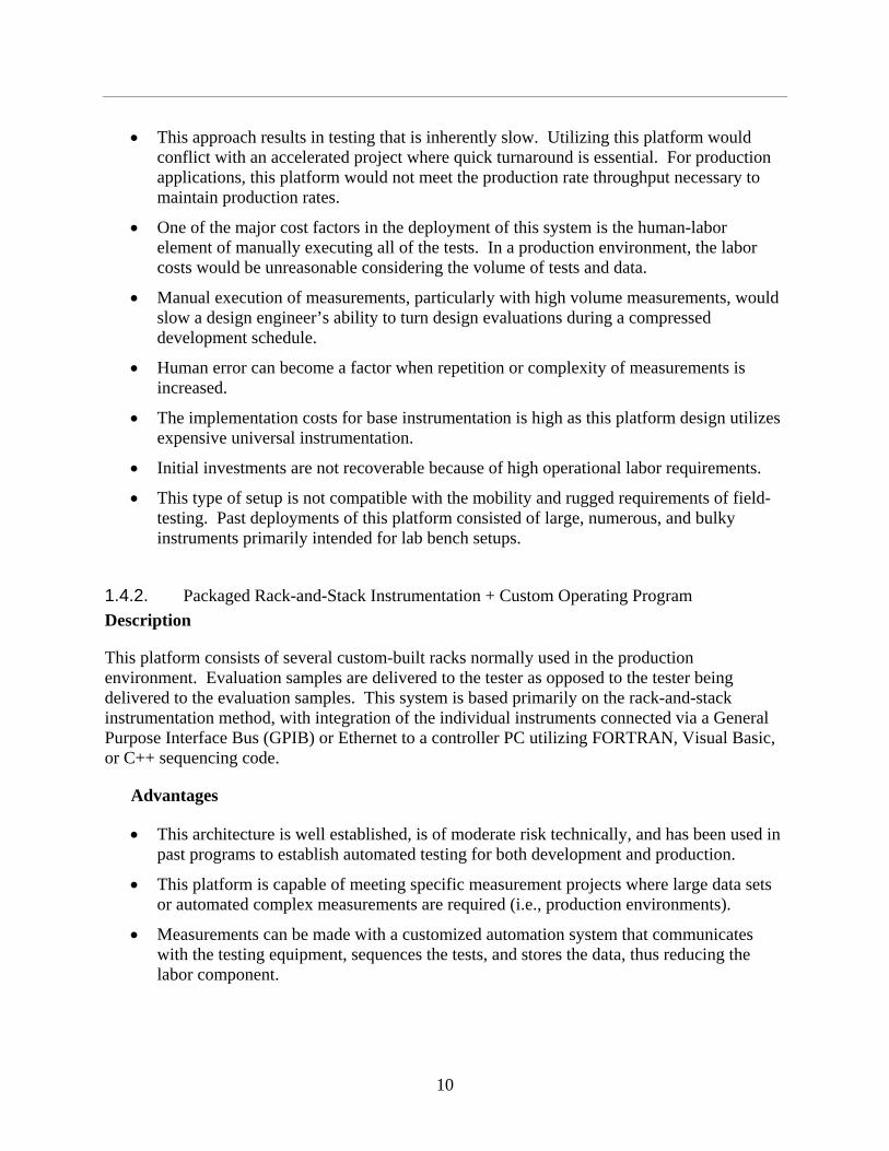
• This approach results in testing that is inherently slow. Utilizing this platform would conflict with an accelerated project where quick turnaround is essential. For production applications, this platform would not meet the production rate throughput necessary to maintain production rates.
• One of the major cost factors in the deployment of this system is the human-labor element of manually executing all of the tests. In a production environment, the labor costs would be unreasonable considering the volume of tests and data.
• Manual execution of measurements, particularly with high volume measurements, would slow a design engineer’s ability to turn design evaluations during a compressed development schedule.
• Human error can become a factor when repetition or complexity of measurements is increased.
• The implementation costs for base instrumentation is high as this platform design utilizes expensive universal instrumentation.
• Initial investments are not recoverable because of high operational labor requirements.
• This type of setup is not compatible with the mobility and rugged requirements of field-testing. Past deployments of this platform consisted of large, numerous, and bulky instruments primarily intended for lab bench setups.
1.4.2. Packaged Rack-and-Stack Instrumentation + Custom Operating Program
Description
This platform consists of several custom-built racks normally used in the production environment. Evaluation samples are delivered to the tester as opposed to the tester being delivered to the evaluation samples. This system is based primarily on the rack-and-stack instrumentation method, with integration of the individual instruments connected via a General Purpose Interface Bus (GPIB) or Ethernet to a controller PC utilizing FORTRAN, Visual Basic, or C++ sequencing code.
Advantages
• This architecture is well established, is of moderate risk technically, and has been used in past programs to establish automated testing for both development and production.
• This platform is capable of meeting specific measurement projects where large data sets or automated complex measurements are required (i.e., production environments).
• Measurements can be made with a customized automation system that communicates with the testing equipment, sequences the tests, and stores the data, thus reducing the labor component.

11
• This design approach is ideal for fixed, rigid applications where changes are few and the application is specific, as occurs with volume measurements, repeated processes, and specific data manipulation.
Disadvantages
• The instrumentation is typically integrated into a rack framework, which is not conducive to field testing. It lacks the mobility of a compact design. Production tester versions are large and not easily convertible to portable systems without reengineering.
• This platform consists of integrated rack-and-stack instrumentation utilizing FORTRAN, Visual Basic, LabVIEW, or C++ programming languages to develop applications that control sequencing. Building and maintaining a custom sequencing engine requires a significant amount of software engineering and is unnecessary because of recent advances in COTS testing software and standardized instrumentation interfaces.
• This design approach lacks the agility to easily adapt to change. Tester functionality changes require reprogramming of the source code and possible hardware modifications. This is monolithic in nature. Monolithic designs are inherently risky when changes occur during the uncertain developmental phases of a project.
• Monolithic testers do not promote code reuse. For every tester, integration of the hardware requires developing interface software for each instrument.
• Because of the complexity of programming in text-based languages like FORTRAN, Visual BASIC, and C++, an advanced programmer, fluent in the higher level programming language, is required for modification of the tester, driving reengineering costs up.
• The implementation costs for customized software and hardware requires a large engineering effort because customized code must be written and custom hardware must be developed for each tester. Equipment costs are also higher with the custom designed and fabricated one-off prototype systems.
• The development timeline for implementation of this platform is similar to the build times for the W76-1 project, about two years for each tester. For the W76-1 program, tester development began midcourse of the project and required several years of development to be ready for production testing.
• The production cost for this architecture would be similar to the production cost for the W76-1 testers, addressing only the needs of production. For the W76-1 program, testers were not implemented during the beginning research and development (R&D) phases of the program. Since each tester is custom, costs are recurring.
• With an assortment of software languages including FORTRAN, Visual BASIC, or C++ code used for the sequencer, cross-platform compatibility and standardization are inhibited.

12
1.4.3. Custom-Hybrid Design with Fabricated Custom-Made, Custom-Built, Hardware
Description
This system architecture is analogous to bread boarding and uses a custom-engineered platform. This approach to tester development is similar to the method used when prototyping basic electronics systems. The hardware consists of custom designed and fabricated circuitry down to the circuit board level. The control and sequencing software is custom written using FORTRAN, Visual Basic, or the C++ programming languages.
This tester platform incorporates some data analysis compatibilities with the control and sequencing software as custom scripts. The architecture incorporates custom software and custom hardware. A framework would have to be written in FORTRAN, Visual Basic, or C++ code. Integration of the hardware would be accomplished by writing interface software for each instrument. The design is complicated by adding the engineering load of developing the base electronic elements in the design.
Advantages
• This design approach offers extreme flexibility as little is predetermined about the architecture. The functionality is bounded by the skill sets of tester designers and the budgetary limits of the project.
• The developed platform is technically achievable and could meet performance requirements of weapons program testing environments.
• This platform facilitates specific measurement capabilities where large data sets or automated complex measurements are required.
• Measurements can be made with a customized automation system that communicates with the testing equipment, sequences the tests, and stores the data, thus reducing the labor component.
• This design approach is ideal for a fixed, rigid application where changes are few and the application is specific for volume measurements, repeated processes, and data manipulation.
Disadvantages
• With the bread-boarded architecture, the platform is not robust. Vulnerabilities to mechanical shock and vibration are limiting factors in field testing. In general, the architecture is not conducive to hostile environments during field testing.
• The control software would be specially written in FORTRAN, Visual Basic, or C++ programming language and as such is not easily modified.
• This strategy does not leverage available commercially developed software solutions. The approach would require a large investment of engineering time to develop prototypes and to fabricate the basic elements of the software design.
13
• This architecture lacks efficiency in implementation because the approach customizes every base element of the design, making development more difficult. The architecture can in some cases be too flexible.
• The engineering risk is higher because of the custom circuitry needed.
• The capacity of this architecture to perform as designed depends on the engineering skill set of the tester designers as they assume all engineering responsibility. This type of platform places the burden of reliability engineering on the tester developers instead of utilizing modular, commercially available products that have undergone reliability engineering by commercial suppliers.
• The development timeline for implementation of this platform increases with the added engineering requirements of a bread-boarded customized platform.
• Each variation of this platform would require a significant investment in engineer labor because of the prototype nature of each design.
• Legacy production systems have used this design approach, and because of the difficulty of modifying these testers, older systems have not been updated to take advantage of newer technologies.

14
This Page Intentionally Left Blank

15
2. CTP – DESIGN INTENT AND CHARACTERISTICS
2.1. Introduction To meet the Complex 2030 transformation goals, traditional tester design strategies based on standalone instruments, custom software applications, and custom-hybrid designs must be reevaluated. These designs lack the flexibility to support dynamic development cycles across the broad spectrum of testing requirements from the initial development phases of weapons programs through the production and surveillance phases. This lack of flexibility has been driven, in part, by the lack of tools available to a test designer. To achieve the flexibility necessary, a modular approach must be realized, building on the advantages that each design strategy provides. The overarching goal of this study is to leverage recent technological advances in test software and learn from past experiences in designing testers. In the subsequent sections, a testing platform capable of achieving standardization across all project phases will be discussed.
In the past, tester designs have been measurement-based, targeted such that code is written for a specific measurement function or to test a specific piece of equipment. The focus has been more on the hardware to build a tester rather than on the software. This is not surprising considering evolution of technology over the past century. Instruments to make measurements have been in use far longer than the software needed to automate those measurements. Prior to the 1980s, test automation consisted of connecting an instrument to a device under test (DUT) and recording measurements by hand or on paper in many cases. There is a large body in the weapons complex that still feels this is the most efficient means to test products. However, this hardware-centric approach to testing leads to monolithic tester design.
The very use of the word automation implies that designs need to be focused more on the software that communicates with instruments and control testers. Any approach to building an automated tester necessarily requires more attention to the operational functionality and how the user interacts with control software. In the last 20 years, software has evolved at a rapid pace, tracking developments in personal computer (PC) technologies. Initial software designs required a software programmer programming in assembly code, Basic, FORTRAN, or other syntax based programming languages. Today tools have been developed and applications are available so that less experienced individuals can develop their own applications. In the tester world, this is also true.
Past tester architectures utilized custom software programs developed in languages such as FORTRAN, LabVIEW, Visual Basic, and C++ and could only be modified by an expert in the applied programming language through reprogramming of the control software code. This approach develops line or visual code that sequences commands to instrumentation to complete a specific measurement, thus limiting adaptation of the automated measurement to change or modification. The architecture makes it extremely difficult to perform measurements not initially defined or to modify the system when requirements change. In fact, in this study, our first design approach was to build a tester leveraging the strengths of LabVIEW as a programming language. The lesson learned was that even though LabVIEW is designed to make communicating with instruments simpler so that anyone can automate a measurement, building

16
full-scale test architecture in LabVIEW is no less expensive and is no more flexible than programming the same tester in C++ or Visual Basic.
Monolithic automated test equipment (ATE) systems, such as highly integrated production testers, are typically very expensive and time consuming to build and can leave engineering teams vulnerable to obsolescence and untimely system redesigns. Historically, after incurring the expense of developing and fielding a custom-build system, there is a reluctance to attempt change to the system. This reluctance is because of the highly customized nature of the design and reluctance to re-incur large costs to modernize the platform.
In response to these trends, the common tester platform (CTP) needs to be based on a core that is implemented as modular, software-defined test architecture based on widely adopted industry standards to provide:
• Increased test system flexibility deployable to a variety of applications, PRTs, and product generations.
• Higher-performance architectures that significantly increase test system throughput and enable tight correlation and integration of instruments from multiple suppliers.
• Lower test system investments by reducing initial capital investment and maintenance cost while increasing equipment use across multiple test requirements, testers, Design Agencies, Production Agencies, the Surveillance Community, and finally the Weapons Complex.
• Increased test system longevity based on widely adopted industry standards that enable technology upgrades to improve performance and adapt to future test requirements.
The goal is for 80 percent of the functionality of any given tester to reside in the core, while the other 20 percent is DUT specific. To meet the points emphasized above, the common core will consist of five tiered-layers where each layer resides on top of and utilizes the next layer. The five layers are system management, data management, application development software, measurement and control services, and computing -measurement bus.
1. System management – Test System Management Software – As an automated test system, the common core requires the implementation of many tasks and measurement functions. Some are specific to the DUT and others are repeated for every device tested. To minimize maintenance costs and ensure test system longevity, it is important that the common core implement a test strategy that separates the DUT-level tasks from the system-level tasks so that engineers can quickly reuse, maintain, and change test programs (or modules) created throughout the development cycle to meet test requirements (Table 1). System management also entails the ability to track requirements and relate them to test steps. In addition, the system-management tool must be versatile to allow for integration with various enterprise networking infrastructures.

17
Table 1. Typical DUT Testing Operations
Operations Different for Each DUT Operations Common for Each DUT
Instrument configuration Operator interfaces
Measurements User management
Data acquisition DUT tracking
Results analysis and presentation Test flow control
Calibration Storing and mining results
2. Data management system – The common core will require a versatile flexible repository for data collected during testing and a means of managing and mining that repository. This data management repository must be standardized and common for all testers used across the three stages of a program. The method of data presentation to the user will necessarily vary depending on the tester, the DUT, or the specific data consumer’s needs. Some common file presentation methods utilized by various engineers are CSV (comma separated value), GEISHA, TDMS, HDF4, HDF5, or MATLAB format. All of these formats would have to be simple conversions extracted from the data in the standard repository.
3. Application development software – The application development environment (ADE), such as Microsoft Visual Basic or LabVIEW, will play a critical role in the common core architectures. With these tools, test engineers can communicate to a variety of instrumentation, integrate measurements, display information, connect with other applications, and much more. Ideally, the ADEs used to develop the common core will provide ease of use, compiled performance, integration of a diverse set of inputs and outputs, and programming flexibility to meet the requirements for the broad range of diverse testers to be supported by the CTP. Factors to consider when selecting an ADE include ease of use, measurement analysis and capabilities, integration with measurement and control drivers, training and support, presentation and reporting features, and protection from obsolescence.
4. Measurement and control services – Measurement and control services play an important role by providing connectivity to various hardware assets in the system, system configuration, and diagnostic tools. Measurement and control services should also provide integration with the application development software layer through application programming interfaces (APIs) so test engineers can easily program all necessary instruments. In fact, the components of this services software; hardware drivers, APIs, and a configuration manager; must seamlessly integrate within the ADE(s) to maximize performance, increase development productivity, and reduce overall maintenance. Important factors to consider include a configuration manager, instrument connectivity, and programming tools.

18
5. Computing and measurement bus – At the center of the common core is a computer in the form of a desktop PC, server workstation, laptop, or embedded computer as used with PCI extensions for instrumentation (PXI). An important aspect of the computing platform is the ability to connect (and communicate) to the wide variety of instruments in a test system. There are several different instrumentation buses available for standalone and modular instruments including GPIB, USB, LAN/LXI, PCI/PXI, and PCI/PXI Express. These buses have differing strengths, making some more suitable for certain applications than others. For example, GPIB has the widest adoption for instrument control and wide availability of instrumentation; USB provides wide availability, easy connectivity, and high throughput; LAN is well-suited for distributed systems; and PCI Express provides the highest data throughput performance.
2.2. CTP – Functional Overview To better understand the CTP concept, an analogy can be made to a master-planned community where a “strategic” approach is applied to the entire community’s needs so that the common infrastructure of the community is designed and developed before the specific structures of the community are established. In likeness to this model for design, the core of the common tester is in comparison the infrastructure of the master-planned community (telecommunications, transportation networks, utilities, recreational, business, etc.) while the specific structures built on this infrastructure would be the specific tester applications within the tester community. Just as the common infrastructure would be established for a master-planned community, the infrastructure of the common tester (user interface, instrument drivers, requirements tracking, report generation, soft front panel templates, data management, flow control, etc.) would be the common foundation on which all tester applications would be constructed.
The CTP architecture must be capable of supporting all functionality common to all weapons systems across multiple existing and future weapons programs. These functionalities include but are not limited to the following:
1. Operational support of an accelerated schedule (laying tracks in front of an oncoming train). This refers to the reduced timeline requirement. To meet this requirement, each stage of the tester must be a subset of the next. The CTP ensures the sharing of common tasks, instruments, functionalities, etc., across multiple testers.
2. Grow with the program. As a weapons program moves along the development path, the tester must be capable of testing at the current development level when that level is ready to be tested. For example, the development levels for a radio detection and ranging (RADAR) program are defined as die, multi-chip-module (MCM), subsystem transmit or receive (Tx or Rx), and full radar. Each level has feature specific tests and tests common to other levels. The CTP will ensure that duplication of tests and functionalities is minimized and that functional test and device reuse is maximized.

19
3. Handle data. The tester must be capable of collecting data, processing at the test station, and storing for later in-depth analysis and data mining. Ideally, data could be collected throughout development through production for comparison over the lifetime of the product.
4. Combine and automate test sequencing. It will be possible to build a test by manually controlling the various instruments necessary to perform that test and then capture the test steps into a sequence for automatic operation. Further, because of the CTP it will be possible to load a sequence from one location into the tester at another location.
5. Be adaptable to add new measurement compatibilities. To keep future development costs low, the common core will easily accommodate new technologies and configurations with seamless integration of testing capabilities, growing the CTP and all spawned testers.
6. Meet advanced technology developmental testing requirements. As new technologies become available, they will be incorporated into various weapon systems. These new technologies will require cutting-edge functionalities that have not yet been applied to tester systems in the nuclear weapons complex. By adding these functionalities to the common core, the CTP and all spawned testers will transparently upgrade to embrace these functionalities.
To meet the constraints listed above the common core needs to be instrument agnostic. In other words, the core should not be built specifically to the requirements of one or more instruments. Instead, the software should provide a means of adaptation to any instrument on any bus. To achieve this goal, the software needs to be modular in its design and approach so that it can be adapted across multiple stages of development and weapons systems (Figure 6).
Figure 6. Application of a Common Platform Overview

20
The CTP core infrastructure must be capable of supporting all tester functionality common to all weapons systems across existing and future weapons programs. Figure 7 shows how a CTP would be applied on a RADAR program. In this figure, an initial core tester platform is developed as the foundation for the building shown in the illustration. After establishment of a solid foundation capable of supporting the successive levels, construction can begin on the successive floors of the building for the specific tester applications in each phase of the project. The CTP is applied at the successive phases of the project (the floors in the illustration RF Die and MCM level, etc.) and customized for the needs of that development phase. It is expected that at each level, there will be specific software and hardware development tasks that may become part of the growing code reuse library. This reuse library would include the drivers developed for instrumentation that can be reapplied as it is reused at each level in the structure.
Figure 7. CTP Structure Using a Core Foundation
Each core component of the CTP foundation is discussed in detail below:
1. User Interface – The foundational User Interface will consist of a developmental environment allowing for complete control and ultimate flexibility of the System Management Software. This user interface will then require some customization to support test engineers at each development level. This will lead to specific user interfaces with defined functionality appropriate to the level of expertise of the end users responsible for each level.
2. Instrument Drivers – A body of instrument drivers will be built to support communication to the wide variety of instruments that will be used in various aspects of

21
tester development. These foundational instrument drivers will be measurement agnostic, allowing for maximum code reusability. At each development level, there will be specific instruments that will require driver development. Unless the instrument driver applies only to measurements at that development level, these drivers will become part of the foundational level.
3. Requirements Tracking – A software mechanism will be provided that will allow for the tracking of requirements as defined in requirements documents provided to the tester development team. Reporting tools will be provided to allow for designers to track every requirement to individual test sequence steps to verify requirements coverage.
4. Report Generation – In the foundation, a basic test report will be provided including all test parameters and instrument configuration settings. At each development level, more customized reports will be necessary, depending on the needs of the developers.
5. Soft Front Panel Templates – A soft front panel (SFP) is the software user interface to instruments. In the foundational level, a template will be defined to allow for quick insertion of instrument-specific code. It provides the user with a graphical method of interacting with an instrument. The SFP communicates to the instrument drivers so that code is reused because the test developer does not have to constantly type code to change or execute instrument functions during test development.
6. Data Management – At the foundational level, a data-management schema will be implemented to efficiently store both metadata and test result data. This data-management technology will be designed so as to provide an easy migration to support development-level data needs. Each development level will require specific conversion, analysis, and reporting capabilities. As with the instrument drivers, new capabilities will be made available to the core library.
7. Flow Control – Flow control refers to the engine that sequences test steps. The flow control scheme will be built to include sequencing, looping, conditional branching, and parallel testing options at the minimum.
2.3. CTP – Architecture The CTP platform consists of the five tiers explained in Section 2.1. The next five subsections are descriptions of each tier as follows:
• System Management Software
• Data Management System
• Application Development Software
• Measurement and Control Services

22
• Computing and Measurement Bus
2.3.1. System Management Software
As mentioned in Section 3.1, in every testing environment, a wide variety of operations must be performed. These operations can be separated into two distinct groups: operations repeated for each product tested and operations different for each product tested. Test management software provides a means to develop an architecture that covers both categories. Architectural design begins with identifying the elements that will be common and building them into the core architecture, then providing a unified means of incorporating tester operations that are different. The system management software then becomes the foundational core of the CTP.
Since system management software is the heart of the infrastructure for the CTP, the choice of tool requires thorough examination. Most companies and enterprises attempting to accomplish similar goals first consider the “build-your-own” concept. In this case, a test executive is built from scratch using a programming language such as C++, Visual Basic, MatLab, or LabVIEW. The goal is to build a sequencing engine and data handler that can be used by multiple teams or individuals. The belief is that by doing so, the software executive will be built such that the organization will be able to incorporate specific features applicable only to that organization. Many companies have found that the ongoing maintenance of the executive and the constant need for modification of the executive are prohibitively and unnecessarily expensive. In addition, most test executive tasks are not unique to an organization. Because of the size of the weapons community and the wide range of technologies that require support, a centralized, maintained, home-grown test executive is unrealistic. There are several benefits to using a COTS solution including the following:
• Reduction in training and in cost associated with documentation
• Opportunity for globalization and cross-site resource sharing
• A standardized test operator interface reduces training and operator errors
• Reduced cost: no need to develop and reengineer the executive
• High potential for reuse
• Decreased maintenance cost
• Greater reliability
An extensive survey of COTS solutions was performed. Tools that were considered included National Instruments TestStand, Agilent TestExec SL, Teradyne Test Studio, MicroLex Systems Sequetest, and Mustangdyne TestCell. The most important requirements for the CTP were as follows:
• Ability to support multiple programming interfaces

23
• Complete suite of flow control capabilities
• Flexibility in terms of data formatting and storage capabilities
• Global support and training options
• Industry adoption
• Company stability
• Nonproprietary user interfaces
• Requirements tracking
Upon review, one product stood out above all the rest, National Instruments (NI) TestStand. TestStand is a ready-to-run test management environment. It is the only choice that meets all the requirements for supporting an organization as diverse as the weapons complex. Test sequences can integrate test modules written in any programming language (e.g., LabVIEW, FORTRAN, Visual Basic, C++, etc.). Operator interfaces can also be written in any language and incorporated seamlessly into the environment. Sequences specify execution flow, reporting, database logging, and connectivity to other enterprise systems. Requirements Tracking is also an integral part of TestStand. NI provides a tool called Requirements Gateway. This tool seamlessly integrates with TestStand sequence steps and the underlying code developed for these steps. It also connects easily with many requirements gathering tools including DOORS, Microsoft Word, Requisite Pro, and Microsoft Excel.
Because of its flexibility and applicability to diverse organizations, TestStand has become the standard test management software choice for 14 of the 15 leading consumer electronics companies (e.g., Sony, Microsoft, Intel, Motorola, etc.) in the world along with 9 of the 10 top contract manufacturers (Flextronics, Solectron, Celestica, etc.) as well as Honeywell Aerospace worldwide. NI is the leader in computer-based measurement and automation software and has a long track record of providing hardware and software tools that scale with technological advancements. NI also provides worldwide support and training options.
The central component of the NI TestStand architecture is an execution engine, which exports an open Application Programming Interface (API) to facilitate communication with other applications. A Sequence Editor and an Operator Interface use the API to access the TestStand Engine (Figure 8). In addition, the TestStand engine provides adapters that allow design to incorporate programming modules written in any language. These modules comprise the specific code that performs actual measurements, communicating with instruments, or analysis routines that could be common or different.
The intent is that a CTP TestStand core model will be developed, remaining open and flexible, but also specific to support weapons programs needs. The CTP TestStand core will manage all aspects of functionality, including data storage and formatting, test module connectivity, sequencing, requirements tracking, operator interface customization, variable handling, conditional branching, looping, user management, and DUT tracking.

24
The result will be a CTP architecture to handle most of the common tester operations while at the same time developing a comprehensive code library of routines that are common.
Figure 8. National Instruments TestStand Architecture
2.3.2. Data Management System
The importance of developing a solid data management scheme cannot be underestimated. Without providing a mechanism for test designers to access the results of tests, the test itself becomes meaningless. In an environment as widespread as the weapons complex, the challenge is to provide a meaningful way for everyone, from design engineer to production test operator, a way to access the data resulting from a test in a way that is meaningful. Each individual has his/her own data needs. In addition, data must be searchable and organized. One tester may provide many files every day, resulting in large-scale archival issues. For these reasons, a common data management system that is open, flexible, mine-able, and efficient is required.
A file format has been defined that provides for the ultimate in efficiency and flexibility. It is a hierarchical system called TDMS. This system consists of two files for every test run. One file is based on XML and the other is a binary file. The XML file contains all the metadata from a test run. XML is an ASCII based hierarchical format. In TDMS, there are three basic levels: file, group and channel level. At each level, properties and parameters can be defined. For example, at the file level, a test can be designed to save information such as the operator’s name, the date and time, or the DUT serial number. At the group level, parameters about a particular measurement or instruments can be stored. At the channel level, vital characteristics about a particular I/O channel can be defined, including statistical information or user-defined dynamic

25
properties. By employing XML, the data scheme is then easily searchable or mine-able. A Google-like search interface has been identified that allows for complex searches over folders of data. The binary data file is used to store actual measurements or instrument data. Binary files are the most efficient method to handle large data sets. Therefore, by combining the flexibility of an ASCII based metadata container and the efficiency of binary files, a test operator is able to leverage the best of each for maximum efficiency and flexibility.
Of equal importance is the ability to convert these data into the format necessary to support the program being served. Currently, several file formats have been identified within the weapons complex: CSV, MATLAB, HDF4, HDF5, GEISHA, and XLS. A conversion from TDMS to one of these formats is seamless, requires very little programming, and can be fully automated. Ideally, a test engineer would only need to click a checkbox to specify which data file format he or she would prefer the data to be exported in. Therefore, with very little effort, results would be immediately available for consumption in the analysis tool or database of his/her choice.
2.3.3. Application Development Software (ADE)
Every tester will have some need for some custom software development using an ADE. However, the TestStand core and the comprehensive reusable code library of the CTP will eliminate the need for every tester to be written from scratch and save, on average, 80 percent of the development time. User interfaces to TestStand and code modules called by TestStand can be written in any language. In addition, multiple ADE environments can be used in the same TestStand sequence. The ultimate goal of choosing which ADE is most appropriate for any given task is that it provides ease of use, compiled performance, integration of a diverse set of inputs and outputs, and programming flexibility to meet the requirements for the broad range of diverse testers to be supported by the CTP.
Since a large part of the initial tester development involves communicating and manipulating instruments, NI LabVIEW has been chosen for this task. LabVIEW is a graphical programming environment designed for exactly this purpose. It is also a complete programming language, simplifying application development for programmers and nonprogrammers. Because of its widespread use in research and development, it is highly likely that many code modules will be developed on this ADE. However, the use of LabVIEW does not preclude the use of other ADEs like C++ or Visual Basic. This approach provides ultimate flexibility in an organization of this size because of the wide variety of expertise available across the complex. In summary, the ADE choice will depend on the specific measurement or instrument control task that is necessary as specified in the tester requirements.
2.3.4. Measurement and Control Services
Measurement and control services play an important role by providing connectivity to various hardware assets in the system, system configuration, and diagnostic tools. These services comprise a software layer that connects actual hardware with application code. Many hardware vendors provide configuration management software to make setup of their hardware simple. In addition, software tools are often provided that combine measurements into a single simple interface. Whenever these tools are available, the CTP will employ these designs.

26
More importantly, instrument drivers are necessary. The term “instrument driver” should not be mistaken for the low-level command and control driver (e.g., DLL) that is needed to functionally operate an instrument. In the test industry, this term refers to higher level code that incorporates all the available commands for an instrument into an easy-to-use interface in a specific programming language or ADE. Because of the wide variety of instruments employed in weapons testing, much of the programming effort will be to convert whatever technology has been provided into a fully functional instrument driver for use in the CTP. This development will be accomplished so as to maximize the possibility for code reuse. To attain this goal, a template has been defined for connecting an instrument driver into the CTP. Once an instrument driver has been converted into the CTP template, it will become part of a large reusable code library and will be available for future projects.
The concept of Interchangeable Virtual Instruments (IVI) is also being explored. IVI instrument drivers are built according to an international standard that has been defined based on instrument classes. The idea is that an instrument (e.g., digital multimeter [DMM]) from one vendor can be swapped out or replaced with an instrument from another vendor without making any changes to the instrument driver. This concept certainly mirrors the CTP concept of reusability and flexibility. For this reason, IVI technologies will be used where applicable.
2.3.5. Computing and Measurement Bus
There are two different buses in a computer-based automated tester, the computing bus and the measurement bus. The computing bus refers to the physical layer connecting the Central Processing Unit (CPU) of a computer to the measurement devices being employed. The measurement bus is the physical mechanism employed to communicate from the computer to an instrument.
Because of its widespread adoption, it is difficult to make a case to not utilize the PCI bus as the computing bus. There are several varieties and extensions to this bus that are popular in the test- and-measurement market. The PXI architecture is a rugged PC-based platform commonly used in test applications. PXI combines PCI electrical-bus features with the rugged, modular, Eurocard packaging of CompactPCI and then adds specialized timing and triggering options for synchronization. It is both a high-performance and low-cost deployment platform for measurement and automation systems. Because it is PC-based, it is widely available and maximally flexible.
Developed in 1997 and launched in 1998, PXI was introduced as an open industry standard to meet the increasing demands of complex instrumentation systems. Today PXI is governed by the PXI Systems Alliance (PXISA), a group of more than 65 companies chartered to promote the PXI standard, ensure interoperability, and maintain the PXI specification. In addition, PXI Express, built on the PCI Express bus, is already in use and shows the most promise for the next 30 years. This technology increases system bandwidth from 120 megabytes (MB)/seconds (sec) to close to 6 gigabytes/sec over dedicated parallel channels. PXI Express has been designed to be 100 percent backward compatible with PXI, primarily because of the large investment in long-term programs similar to those in the weapons complex.

27
The measurement or instrument bus comes in a variety of physical forms. These buses are typically compared by considering the bandwidth and latency. Bandwidth measures the rate at which data are sent across the bus, typically in MB/sec. A high-bandwidth bus can transmit more data in a given amount of time than a bus with low bandwidth. Bandwidth is important because it affects whether data can be sent across the bus to or from the PXI bus as fast as it is acquired or generated. This, in turn, affects how much onboard memory the instruments will need. Bandwidth is important in applications such as complex waveform generation and acquisition as well as RF and communications applications.
Latency, another critical characteristic, measures the delay in data transmission across the bus. By analogy, if we were to compare an instrumentation bus to a highway, bandwidth would correspond to the number of lanes and the speed of travel, while latency would correspond to the delay introduced at the on and off-ramps. A bus with low (meaning good) latency would introduce less delay between the time data were transmitted on one end and processed on the other end. Latency, while less observable than bandwidth, has a direct impact on applications where a quick succession of short commands are sent across the bus, such as in handshaking between a digital multimeter and switch, and in instrument configuration. Figure 9 charts the bandwidth (and latency) of many standard instrumentation buses.
In addition to the bandwidth vs. latency comparison, each bus has its own unique advantages. For this reason, a hybrid approach is necessary in the CTP. The CTP will employ whatever bus technology is necessary, and each of these instrument buses connects directly with the PXI-based computing bus seamlessly.
The CTP is bus agnostic and is not limited to PXI alone but is expandable, supporting any bus. This flexibility allows the inclusion of currently used buses to the tester architecture (e.g., GPIB, LXI, Serial, etc.) as well as expandability to include future bus technologies.
.
Figure 9. Bandwidth Chart

28
2.4. CTP – Implementation This section describes the process for building and implementing a common tester platform.
2.4.1. Implementation Infrastructure
A test platform of this magnitude requires the involvement of several entities and experts in many areas. For the initial core test platform and template development, development requires software programmers with not only test industry experience, but also architectural expertise in the development environments at the highest level. For TestStand and LabVIEW, a two-tiered certification program exists in which a programmer can attain certifications as a developer and as an architect. To receive certification as an architect, the programmer must have significant experience with large-scale systems that span multiple application needs. Since the core system is based on TestStand, a TestStand Certified Architect is required. For portions that require LabVIEW, the programmer should be at least at the Developer level.
Since both LabVIEW and TestStand are NI products, direct involvement from NI R&D and field engineers is necessary. An earlier attempt was made to involve only systems integrators with proficiencies in these areas. Because these integrators tend to have narrow scope, the project was not as successful as it could have been. Through that experience, it became obvious that only the company that developed the tools has the scope and experience to ensure that the tools are applied appropriately.
Sandia National Laboratories (SNL) is where weapons designs originate. The CTP concept begins with testers developed for Design Engineers at the component level. For these original CTP designs to be successful, it is critical that the CTP core design team be embedded at SNL and work hand-in-hand with these designers. Only in that way can full comprehension be achieved to build successful testers that meet the needs properly.
Once the core has matured and it is applied at the assembly level, it is critical that the Kansas City Plant (KCP) be involved in tester development for the future. KCP should become the owners and caretakers of the CTP. KCP offers production tester experience in weapons programs that far eclipses what any other entity could provide. KCP also provides significant experience in the customization of hardware that is non-COTS and programming in Visual Basic, a common ADE used for application development. As development of the CTP expands, involvement from KCP will increase. KCP test engineers should be trained in the use of the CTP at some point. In addition, the appropriate test engineers may want to consider formal training and certification in at least TestStand.
It is absolutely essential that all these entities participate in the CTP at various points in time. As the program expands, it is likely that more programmers and entities might be employed based on the need for specific expertise at that time.
2.4.2. CTP Qualification
A common train of thought in the establishment is that the actual development tools or ADEs need qualification as opposed to the applications developed with these tools. Programming languages such as Microsoft Visual C++, Microsoft Visual Basic, and NI LabVIEW, and tools

29
such as The Mathworks MATLAB, NI TestStand, and DIAdem fall into the category of abstractions from assembly-level code. These languages and tools should not be considered as needing qualification except through verification testing that they do what they claim to do and perform as intended. Instead, the actual applications developed with these tools need to be fully qualified at all levels.
The qualification plan for the application called the CTP must comply with the regulator guidelines established in the Weapon Quality Policy (QC-1) document. The requirements specified in the QC-1 document are not applicable to all aspects of research but must be applied to weapon development, engineering, production, surveillance, and dismantlement of which the common tester platform would become a part. Thus, to qualify a tester design, the qualification requirements, whenever practical, should be applied early in the design processes for later transition to the production and surveillance activities.
Contractors involved in the CTP will need to integrate quality principles with risk-based analysis into management and work practices at all levels so that missions are accomplished, and customer requirements are met. Organizations shall integrate quality management into all facets of work planning and execution. A written quality assurance plan (QAP) or (WQAP) should be developed, implemented, and maintained that meets the requirements of this document.
There will be a process to establish and document the CTP organizational structure, functional responsibilities, levels of authority, and lines of communication. Where more than one organization is involved in the execution of activities, the responsibilities, interfaces, and authorities of each organization should be clearly defined and documented. The external interfaces between organizations and the internal interfaces between organizational units, and changes thereto, should be documented. Personnel verifying quality achievement should not be directly responsible for performing the work being evaluated and should have the authority, direct access to management, organizational freedom, and access to work to perform their function.
The organization responsible for the CTP design should ensure that operating, production, and quality requirements are incorporated in the design process as early as feasible. The design process should provide for the timely identification and evaluation of key elements that are critical to program success and provide an objective means to measure design, product, process, and production readiness. Producibility should be formally addressed in the design and design change processes. The design authority and production organization should establish and document a process for evaluating producibility. This process should require the design and production organizations to evaluate and document their estimates of the yield, cycle time, and associated costs of options in product designs, manufacturing processes, production and support systems, and tooling. Beginning with development and continuing throughout the life-cycle of the activity, processes should be in place to identify, document, validate, control, and maintain customer requirements. Each organization should document its process, including roles, responsibilities, and interfaces.

30
A risk-management process should be used to determine the extent of formal planning (including quality plans) required for development, programs, projects, processes, activities, materials, products, services, functions, product and stockpile certification, or organizational entities.
2.4.3. Implementation Budget
The primary purpose of developing the CTP is to introduce efficiencies and lower the overall cost of testing by as much as 70–90 percent. The initial CTP design will not necessarily cost less at the outset. True cost savings may not be realized until a significant reusable code base exists. Initial designs may appear to be as costly as building a monolithic tester both in time and actual dollars. However, by building on test designs and reusing code as the weapon matures, development time and cost will dramatically decrease as shown in Figure 10. At the die level, testing is more complex than at the production or stewardship levels. However, more flexibility will be gained in development testing, allowing for more complete characterization of components, leading to an overall reduced programmatic risk because of decreased uncertainty in design.
2.4.4. Implementation Plan
The first application of the common tester architecture is in support of a next-generation AFS development project. Tester development would follow the progression of the AFS project, starting with the establishment of a core platform that will evolve as the testing requirements change with maturation of the design. The initial test development team consists of the primary SNL leadership team for project management, a TestStand Certified Architect, a TestStand Certified Developer, two LabVIEW Certified Developers, local NI field personnel for coordination, and various key personnel from within NI’s corporate structure. In addition to developing the CTP software, this team is developing an appropriate qualification plan as well as the first stages of the CTP core.
Figure 10 illustrates the evolution of the AFS program, and a phased approach to tester design is presented. At each stage in the design, the tester development team plans to put systems into operation so that the tester can be used immediately, allowing for immediate input. This same approach will continue to be used throughout the weapons program. As each tester reaches maturation, there will be a “hand-off” to test operators to include training in the current architectural design.

31
Figure 10. AFS Development Phased Approach to Tester Design
For the AFS program, the first phase of testing involves RF Die level testing. This type of testing requires the deployment of the tester with a microprobe station to support evaluation of RFIC prototype designs. As the RFIC designs mature, the test platform will mature and move towards MCM testing. At that point in time, the CTP architecture can be applied in other areas of the complex as well as in support of the MCM level.
Figure 11 is an initial schematic of the overall architecture of the Die level tester. Software development takes considerably more time and is in process at this point. Six instrument drivers have been completed along with integration of these instruments into the CTP TestStand architecture. In addition, a viable Data Management scheme has been defined and implemented for demonstration. From the hardware perspective for Phase I and Phase II, the design is complete with a CTP that supports a variety of instruments over multiple buses. A Software Requirements Specification (SRS) for the CTP is also under development.

32
Figure 11. Die Level Tester Schematic
Phase II would support the subsystem level of development. The first versions of subsystems, the Tx and Rx subsystems will shift the testing activities to the next tier of system level design. At this point, Test Designers from KCP should become involved. A complete list of required measurements for this stage is shown in Table 2 and Table 3.

33
Table 2. Tx Measurement Matrix
Tx Components
Test
Tx Assembly
Power Amplifier
Switched Amplifier
PLL/DDS Oscillator
Fast Switched
Attenuator QPSK
Modulator
Low Power Limiter
RF Bandpass
Filter
Mixer Test (Up Convert)
DC Bias & Control Line Currents/Low Freq Voltage X X X X X X X Low Freq Voltage – Temp Sensor X X X X X X X X X IF Oscillator Frequency X RF Out Frequency X X Isolation (Tx/Rx, RF/IF/LO – up to 23 dBm) X X Pout vs. Frequency X X X X
Pout vs. Pin ( includes P1dB compression) X X X X X X Gain vs. Frequency at some Pin X Gain Flatness X X Pout Flatness X X Efficiency vs. Frequency X
RF Envelope Timing Parameters (tr, tf, ton, pulse width) X X X General Timing Measurements X X 200 nSec turn off (150 dB dynamic range) X AM to PM Evaluation X IP3 Two Tone 3rd Order Intercept X X X X Stability Into All Phase Load During TXP Modulation X X Harmonic Content and Spurs X S11/S22/S33 Return Loss X X X X X High Power Return Loss X S21 Gain/Rejection X X X X X Group Delay Time Domain Impulse Response 0 Time Fed Thru 3rd and 5th Order Time Products Noise Figure X X Phase Noise X Frequency Tuning Speed X Frequency Pulling Into All Phase 2:1 VSWR X Spurious Spectral Content X X Insertion Phase vs. Frequency X Phase and Amplitude Imbalance Between all Phase States X Conversion Loss (Maybe S21) X

34
Table 3. Rx Measurement Matrix
Rx Components
Measurements Rx
Assembly Switched Amplifier
IF Bandpass
Filter IF
Oscillator Dynamic
Modulator
Mixer Test (Dn
Convert)
DC Bias & Control Line Currents/Low Freq Voltage X X X Low Freq Voltage – Temp Sensor X X X X X IF Oscillator Frequency RF Out Frequency X X Isolation (Tx/Rx, RF/IF/LO – up to 23 dBm) Pout vs. Frequency X Pout v. Pin ( includes P1dB compression) X X Gain vs. Frequency at some Pin Gain Flatness X Pout Flatness Efficiency vs. Frequency RF Envelope Timing Parameters (tr, tf, ton, pulse width) General Timing Measurements X 200 nSec turn off (150 dB dynamic range) AM to PM Evaluation IP3 Two Tone 3rd Order Intercept X X Stability Into All Phase Load During TXP Modulation X Harmonic Content and Spurs S11/S22/S33 Return Loss X X High Power Return Loss S21 Gain/Rejection/Ripple X X Group Delay X Time Domain Impulse Response 0 Time Fed Thru X 3rd and 5th Order Time Products X Noise Figure X X Phase Noise Frequency Tuning Speed Frequency Pulling Into All Phase 2:1 VSWR Spurious Spectral Content Insertion Phase vs. Frequency Phase and Amplitude Imbalance Between all Phase States Conversion Loss (Maybe S21) X

35
The third phase of tester development would support the integration of the subsystems into the full AFS system level of prototype deployment. At this level of development, many of the component level, detailed measurements, would be replaced with system level measurements to evaluation the performance of a higher system level of performance criteria.
A more specific description of the subsystems is shown in Figure 12. This figure schematically presents a rough timeline for when the component assembly technologies converge to produce the AFS. During Phase 1, subsequent to completion of the core CTP architecture’s implementation at the die level, subsystem tester components will be developed.
The underlying code for the application-specific integrated circuit (ASIC) simulator is under development. In addition, two components of the foundational bus subsystem are reaching completion, namely, the BERT and the bus monitor. Following completion of the CTP architecture development, “instrument drivers” that comply with the CTP template will be developed. Designers of these subsystems are engaged with the CTP design team.
Figure 12. Radar and Tester Development Timeline

36
This Page Intentionally Left Blank

37
3. CONCLUSION The objective of this study was twofold: (1) to understand the extent of tester application requirements within the phases of a weapons program and across analogous weapons programs and (2) to determine the extent to which the tenets of the common tester platform can meet these requirements while also fulfilling the transformation strategic goals identified in the Complex 2030 initiative. Through careful review of current architectures that are in use, it was determined that the current weapons tester equipment is bulky, inefficient, and incapable of responding to rapid technological changes or advancements. If the community is to meet the strategic goals of Complex 2030, a paradigm shift to tester development must occur.
This paradigm shift involves moving away from the idea that tester development can only begin after a product has been built. Testing needs must be considered at all levels of weapons design. By leveraging COTS technologies and test code written for design engineers building components, overall resource costs will decrease as a weapon moves towards production.
An architecture called the CTP was introduced and described that we believe will meet the goals of the NNSA. At the heart of the CTP is the notion of reuse, both reusing COTS technologies already tried and proven in the marketplace and reusing technologies developed for reapplication at other levels. It is believed that anywhere from 70–90 percent of the development that occurs when building testers can be reused in other projects. However, these testers must conform to a standard platform.
3.1. Caveats The WR community realizes that a new approach to testing is needed, and much informal discussion is now occurring about this topic. The current methodology of tester development for WR activities has been under scrutiny from stakeholders that are questioning the methodologies, costs, and time for the realization of a final product. Movements are under way from all directions within the WR community in pursuit of a new tester platform. This “armchair quarterbacking” has created a competitive and divided effort with fragmented attempts within the community to be the first to develop a cost-effective standardized platform. This divided, competitive environment lends itself to failure because of the use of under qualified skill sets of software architects attempting to develop a complex and advanced software product beyond the talent sets required for success. These initiatives are originating from elements that traditionally do not become involved in tester development; however, frustrations with the current process have led to independent efforts with narrow agendas to tester designs. The tester status quo is also clamoring to develop a new approach to the testers of the future while sensing the undercurrents for change, but not accepting that extension may occur in the drive to change.
The weapons complex will have a substantial effort to equip the complex with an integrated standardized common tester platform capability. This study found that the possibility of implementing a standardized platform is obtainable with the current state of technology and the pressures for efficiency and cost reduction. The commitment must be made by management to effect this change for all of the stakeholders in a unified manner; otherwise success could be in jeopardy.

38
Distribution 1 MS0899 Technical Library 9536 (electronic copy)
2 MS0348 Michael J. Hurst 5353
1 MS0529 Kent D. Meeks 5350
1 MS0348 Tedd A. Rohwer 5353
1 MS0348 Richard T. Knudson 5353
1 MS0348 Perry A. Molley 5351
1 MS0348 John A. Dye 5351
1 MS0348 George R. Laguna 5353
1 MS0348 Gerald M. Boyd 5251
1 MS0447 James D. Mangum 2231
1 MS1330 Judd Rohwer 5342
1 MS0340 John L. Williams 2137
1 MS0447 Sam G. Sevier 2111
1 MS0447 David P. Clements 2111
1 MS2257 Phil D. Hoover 2111
1 MS0435 Marlene E. Uribe 2122
5 MS0435 Department 2111 file 2111